WO2010058681A1 - Optically isotropic liquid crystal medium and optical element - Google Patents
Optically isotropic liquid crystal medium and optical element Download PDFInfo
- Publication number
- WO2010058681A1 WO2010058681A1 PCT/JP2009/068393 JP2009068393W WO2010058681A1 WO 2010058681 A1 WO2010058681 A1 WO 2010058681A1 JP 2009068393 W JP2009068393 W JP 2009068393W WO 2010058681 A1 WO2010058681 A1 WO 2010058681A1
- Authority
- WO
- WIPO (PCT)
- Prior art keywords
- liquid crystal
- alkyl
- replaced
- hydrogen
- crystal composition
- Prior art date
Links
- 0 *c(cc1)ccc1-c1ccc(C2COc3ccc(cccc4)c4c3-c(c3ccccc3cc3)c3OC2)cc1 Chemical compound *c(cc1)ccc1-c1ccc(C2COc3ccc(cccc4)c4c3-c(c3ccccc3cc3)c3OC2)cc1 0.000 description 3
- WKSSVPZCTNGECT-UHFFFAOYSA-N Cc(cc1)ccc1-c1ccc(C2COc3ccc(cccc4)c4c3-c(c(cccc3)c3cc3)c3OC2)cc1 Chemical compound Cc(cc1)ccc1-c1ccc(C2COc3ccc(cccc4)c4c3-c(c(cccc3)c3cc3)c3OC2)cc1 WKSSVPZCTNGECT-UHFFFAOYSA-N 0.000 description 1
Images


Classifications
-
- C—CHEMISTRY; METALLURGY
- C09—DYES; PAINTS; POLISHES; NATURAL RESINS; ADHESIVES; COMPOSITIONS NOT OTHERWISE PROVIDED FOR; APPLICATIONS OF MATERIALS NOT OTHERWISE PROVIDED FOR
- C09K—MATERIALS FOR MISCELLANEOUS APPLICATIONS, NOT PROVIDED FOR ELSEWHERE
- C09K19/00—Liquid crystal materials
- C09K19/04—Liquid crystal materials characterised by the chemical structure of the liquid crystal components, e.g. by a specific unit
- C09K19/06—Non-steroidal liquid crystal compounds
- C09K19/08—Non-steroidal liquid crystal compounds containing at least two non-condensed rings
- C09K19/10—Non-steroidal liquid crystal compounds containing at least two non-condensed rings containing at least two benzene rings
- C09K19/20—Non-steroidal liquid crystal compounds containing at least two non-condensed rings containing at least two benzene rings linked by a chain containing carbon and oxygen atoms as chain links, e.g. esters or ethers
-
- C—CHEMISTRY; METALLURGY
- C09—DYES; PAINTS; POLISHES; NATURAL RESINS; ADHESIVES; COMPOSITIONS NOT OTHERWISE PROVIDED FOR; APPLICATIONS OF MATERIALS NOT OTHERWISE PROVIDED FOR
- C09K—MATERIALS FOR MISCELLANEOUS APPLICATIONS, NOT PROVIDED FOR ELSEWHERE
- C09K19/00—Liquid crystal materials
- C09K19/52—Liquid crystal materials characterised by components which are not liquid crystals, e.g. additives with special physical aspect: solvents, solid particles
- C09K19/58—Dopants or charge transfer agents
- C09K19/586—Optically active dopants; chiral dopants
- C09K19/588—Heterocyclic compounds
-
- C—CHEMISTRY; METALLURGY
- C09—DYES; PAINTS; POLISHES; NATURAL RESINS; ADHESIVES; COMPOSITIONS NOT OTHERWISE PROVIDED FOR; APPLICATIONS OF MATERIALS NOT OTHERWISE PROVIDED FOR
- C09K—MATERIALS FOR MISCELLANEOUS APPLICATIONS, NOT PROVIDED FOR ELSEWHERE
- C09K19/00—Liquid crystal materials
- C09K19/04—Liquid crystal materials characterised by the chemical structure of the liquid crystal components, e.g. by a specific unit
- C09K2019/0444—Liquid crystal materials characterised by the chemical structure of the liquid crystal components, e.g. by a specific unit characterized by a linking chain between rings or ring systems, a bridging chain between extensive mesogenic moieties or an end chain group
- C09K2019/0466—Liquid crystal materials characterised by the chemical structure of the liquid crystal components, e.g. by a specific unit characterized by a linking chain between rings or ring systems, a bridging chain between extensive mesogenic moieties or an end chain group the linking chain being a -CF2O- chain
-
- C—CHEMISTRY; METALLURGY
- C09—DYES; PAINTS; POLISHES; NATURAL RESINS; ADHESIVES; COMPOSITIONS NOT OTHERWISE PROVIDED FOR; APPLICATIONS OF MATERIALS NOT OTHERWISE PROVIDED FOR
- C09K—MATERIALS FOR MISCELLANEOUS APPLICATIONS, NOT PROVIDED FOR ELSEWHERE
- C09K2323/00—Functional layers of liquid crystal optical display excluding electroactive liquid crystal layer characterised by chemical composition
-
- G—PHYSICS
- G02—OPTICS
- G02F—OPTICAL DEVICES OR ARRANGEMENTS FOR THE CONTROL OF LIGHT BY MODIFICATION OF THE OPTICAL PROPERTIES OF THE MEDIA OF THE ELEMENTS INVOLVED THEREIN; NON-LINEAR OPTICS; FREQUENCY-CHANGING OF LIGHT; OPTICAL LOGIC ELEMENTS; OPTICAL ANALOGUE/DIGITAL CONVERTERS
- G02F1/00—Devices or arrangements for the control of the intensity, colour, phase, polarisation or direction of light arriving from an independent light source, e.g. switching, gating or modulating; Non-linear optics
- G02F1/01—Devices or arrangements for the control of the intensity, colour, phase, polarisation or direction of light arriving from an independent light source, e.g. switching, gating or modulating; Non-linear optics for the control of the intensity, phase, polarisation or colour
- G02F1/13—Devices or arrangements for the control of the intensity, colour, phase, polarisation or direction of light arriving from an independent light source, e.g. switching, gating or modulating; Non-linear optics for the control of the intensity, phase, polarisation or colour based on liquid crystals, e.g. single liquid crystal display cells
- G02F1/133—Constructional arrangements; Operation of liquid crystal cells; Circuit arrangements
- G02F1/1333—Constructional arrangements; Manufacturing methods
- G02F1/1343—Electrodes
- G02F1/134309—Electrodes characterised by their geometrical arrangement
- G02F1/134363—Electrodes characterised by their geometrical arrangement for applying an electric field parallel to the substrate, i.e. in-plane switching [IPS]
Definitions
- the present invention relates to a liquid crystal medium useful as a material for an optical element. Specifically, the present invention relates to a liquid crystal medium having a wide liquid crystal phase temperature range, a large dielectric anisotropy, and a refractive index anisotropy. In addition, the present invention relates to an optical element using the liquid crystal medium. Specifically, the present invention relates to an optical element that can be used in a wide temperature range, can be driven at a low voltage, and can obtain a high-speed electro-optic response.
- An optical element refers to various elements that perform functions such as optical modulation and optical switching using the electro-optic effect. For example, display elements (liquid crystal display elements), optical communication systems, optical information processing, and various sensors. The light modulation element used for a system is mentioned.
- Liquid crystal display elements using a liquid crystal composition are widely used in displays such as watches, calculators, word processors and the like. These liquid crystal display elements utilize the refractive index anisotropy and dielectric anisotropy of liquid crystal compounds.
- PC phase change
- TN twisted nematic
- STN super twisted nematic
- BTN Battery twisted nematic
- ECB mainly using one or more polarizing plates
- ECB Known are electrically controlled birefringence (OCB), optically compensated bend (OCB), in-plane switching (IPS), and vertical alignment (VA).
- OCB electrically controlled birefringence
- OCB optically compensated bend
- IPS in-plane switching
- VA vertical alignment
- a mode in which an electric field is applied in an optically isotropic liquid crystal phase to develop electric birefringence has been actively studied (Patent Documents 1 to 9, Non-Patent Documents 1 to 3).
- wavelength tunable filters, wavefront control elements, liquid crystal lenses, aberration correction elements, aperture control elements, optical head devices, etc. that utilize electrical birefringence in the blue phase, which is one of the optically isotropic liquid crystal phases, have been proposed.
- Patent Documents 10 to 12 The classification based on the element driving method is PM (passive matrix) and AM (active matrix). PM (passive matrix) is classified into static and multiplex, and AM is classified into TFT (thin film transistor) and MIM (metal insulator metal).
- liquid crystal display elements contain a liquid crystal composition having appropriate physical properties.
- the liquid crystal composition preferably has appropriate physical properties.
- General physical properties necessary for the liquid crystal compound which is a component of the liquid crystal composition are as follows. (1) being chemically stable and physically stable; (2) having a high clearing point (liquid crystal phase-isotropic phase transition temperature); (3) The lower limit temperature of the liquid crystal phase (nematic phase, cholesteric phase, smectic phase, blue phase or other optically isotropic liquid crystal phase) is low, (4) Excellent compatibility with other liquid crystal compounds, (5) having an appropriate amount of dielectric anisotropy; (6) having an appropriate refractive index anisotropy; It is.
- a liquid crystal compound having a large dielectric anisotropy and refractive index anisotropy is preferable from the viewpoint of reducing driving voltage.
- the voltage holding ratio can be increased.
- the temperature range of a nematic phase or an optically isotropic liquid crystal phase is set. It can be expanded and can be used as a display element in a wide temperature range.
- the liquid crystal compound is generally used as a liquid crystal composition prepared by mixing with many other liquid crystal compounds in order to develop characteristics that are difficult to be exhibited by a single compound.
- the liquid crystal compound used in the liquid crystal display element preferably has good compatibility with other liquid crystal compounds and the like as shown in (4).
- the liquid crystal display elements that have particularly higher display performance such as contrast, display capacity, response time characteristics, and the like.
- a liquid crystal composition having a low driving voltage is required for the liquid crystal material used.
- Patent Documents 1 to 3 and Non-Patent Documents 1 to 3 disclose the voltage required for the operation of the element.
- Patent Documents 4 to 9 disclose an optically isotropic liquid crystal composition and a polymer / liquid crystal composite material in which a reduction in operating voltage is expected from the above, the optically isotropic liquid crystal composition of the present application is disclosed. There is no description pronounced of materials and polymer / liquid crystal composite materials.
- JP 2003-327966 A International Publication No. 2005/90520 Pamphlet JP 2005-336477 A JP 2006-89622 A JP 2006-299084 A JP 2006-506477 A JP 2006-506515 A International Publication No. 2006/063662 Pamphlet JP 2006-225655 A JP-A-2005-157109 International Publication No. 2005/80529 Pamphlet JP 2006-127707 A
- the first object of the present invention is to provide an optically isotropic liquid crystal phase having stability to heat, light, etc., a wide liquid crystal phase temperature range, a large refractive index anisotropy, and a large dielectric anisotropy. It is to provide a liquid crystal medium having the same.
- the second object is to provide various optical elements that contain this liquid crystal medium, can be used in a wide temperature range, have a short response time, a large contrast, and a low driving voltage.
- liquid crystal composition having an optically isotropic liquid crystal phase mainly comprising a compound comprising a CF 2 O— linking group is suitable.
- the present invention provides the following liquid crystal medium (liquid crystal composition or polymer / liquid crystal composite), an optical element containing the liquid crystal medium, and the like.
- a liquid crystal composition comprising an achiral component T containing a compound represented by the formula (1) and a chiral agent and exhibiting an optically isotropic liquid crystal phase.
- R 1 is hydrogen or alkyl having 1 to 20 carbon atoms, and any —CH 2 — in the alkyl is —O—, —S—, —COO—, —OCO—, —CH ⁇ CH—, —CF ⁇ CF—, or —C ⁇ C— may be substituted, and any —CH 2 — in the alkyl or alkyl may be replaced by —O—, —S—, —COO—.
- Any hydrogen in the group replaced by —OCO—, —CH ⁇ CH—, —CF ⁇ CF— or —C ⁇ C— may be replaced by halogen or alkyl having 1 to 3 carbons;
- Z 1 , Z 2 , and Z 3 are each independently a single bond, —COO— or —CF 2 O—, but at least one is —CF 2 O—;
- L 1 , L 2 , L 3, L 4, and L 5 are independently hydrogen or fluorine;
- any —CH 2 — in the alkyl and in the alkyl may be —O—, —S—, —COO—, —OCO—, —CH ⁇ CH—, —CF ⁇ CF— or — Any
- R 1 is alkyl having 1 to 20 carbon atoms, alkenyl having 2 to 21 carbon atoms, alkynyl having 2 to 21 carbon atoms, alkoxy having 1 to 19 carbon atoms, or 2 to 20 carbon atoms.
- X 1 is hydrogen, halogen, —SF 5 , —CH 2 F, —CHF 2 , —CF 3 , — (CH 2 ) 2 —F, —CF 2 CH 2 F, —CF 2 CHF 2 , —CH 2 CF 3 , —CF 2 CF 3 , — (CH 2 ) 3 —F, — (CF 2 ) 3 —F, —CF 2 CHFCF 3 , —CHFCF 2 CF 3 , — (CH 2 ) 4 —F, — (CF 2 ) 4 -F, — (CF 2 ) 4 -F, — (CF 2 ) 4 -F,-(CH 2 ) 5 -F,-(CF 2
- R1 are a group represented by any one of formulas (CHN-1) to (CHN-19), and R 1a is hydrogen or alkyl having 1 to 20 carbons.
- the liquid crystal composition according to any one of [3].
- the liquid crystal composition according to item [1], comprising at least one compound selected from the group of compounds represented by formulas (1-1) to (1-3).
- R 1 is a group represented by any one of formulas (CHN-1) to (CHN-19), R 1a is hydrogen or alkyl having 1 to 20 carbons; L 1 , L 2 , L 3 , L 4 and L 5 are independently hydrogen or fluorine;
- X 1 is fluorine, chlorine, —CF 3 , —CHF 2 , —CH 2 F, —OCF 3 , — OCHF 2 , —OCH 2 F, —OCF 2 CFHCF 3 or —CH ⁇ CHCF 3 )
- R 1 is any one of the formulas (CHN-1) to (CHN-4) and (CHN-6) to (CHN-8).
- L 6 , L 7 , and L 8 are independently hydrogen or fluorine;
- X 2 is fluorine, chlorine, —CF 3 , — CHF 2, -CH 2 F, -OCF 3, -OCHF 2, -OCH 2 F, -OCF 2 CFHCF 3
- l, m, n, o, and p are independently 0 or 1, and l + m + n + o + p ⁇ 4).
- R 2 is hydrogen or alkyl having 1 to 20 carbon atoms, and any —CH 2 — in the alkyl is —O—, —S—, —COO—, —OCO. —, —CH ⁇ CH—, —CF ⁇ CF— or —C ⁇ C— may be substituted, and any —CH 2 — in the alkyl or alkyl may be replaced by —O—, —S—, — Any hydrogen in the group replaced with COO—, —OCO—, —CH ⁇ CH—, —CF ⁇ CF— or —C ⁇ C— may be replaced with halogen or alkyl having 1 to 3 carbon atoms.
- L 6, L 7, and L 8 are independently hydrogen or halogen;
- X 2 Is hydrogen, halogen, —C ⁇ N, —N ⁇ C ⁇ S, —C ⁇ C—C ⁇ N, —SF 5 , or alkyl having 1 to 10 carbon atoms, and in this alkyl, any —CH 2 — May be replaced by —O—, —S—, —CH ⁇ CH—, or —C ⁇ C—, and any —CH 2 — in the alkyl and in the alkyl is —O—, — Any hydrogen
- the achiral component T comprises 5 to 95% by weight of the compound represented by the formula (1), 5 to 80% by weight of the compound represented by the formula (2), and 0 to 50% by weight of other compounds.
- Item 10 The liquid crystal composition according to any one of items [1] to [9],
- the achiral component T comprises 5 to 94% by weight of the compound represented by the formula (1), 5 to 80% by weight of the compound represented by the formula (2), and 1 to 50% by weight of other compounds.
- Item 10 The liquid crystal composition according to any one of items [1] to [9],
- the achiral component T contains 10 to 100% by weight of a compound selected from the group consisting of formulas (1-2A) to (1-2H) and formulas (1-3A) to (1-3D) A liquid crystal composition represented by any one of items [1] to [13].
- R 1 is a chain selected from the formulas (CHN-1), (CHN-4), (CHN-7), (CHN-8) and (CHN-11);
- X 1 is fluorine, chlorine, —CF 3 , —CHF 2 , —CH 2 F, —OCF 3 , —OCHF 2 , —OCF 2 CFHCF 3 or —CH ⁇ CHCF 3 )
- the achiral component T further contains at least one compound selected from the group of compounds represented by each of formulas (7), (8), (9), (10) and (11). Item 16.
- the liquid crystal composition according to any one of items [1] to [14]. (In these formulas, R 5 and R 6 are independently alkyl having 1 to 10 carbons or alkenyl having 2 to 10 carbons, and any hydrogen in alkyl and alkenyl may be replaced by fluorine.
- any —CH 2 — may be replaced by —O—;
- ring D 1 , ring D 2 , ring D 3 and ring D 4 are independently 1,4-cyclohexylene, 1,4-cyclohexenylene, 1,4-phenylene, 1,4-phenylene in which arbitrary hydrogen is replaced by fluorine, tetrahydropyran -2,5-diyl, or decahydronaphthalene-2,6-diyl;
- Z 13 , Z 14 , Z 15 , and Z 16 are independently-(C H 2 ) 2 —, —COO—, —CH 2 O—, —OCF 2 —, —OCF 2 (CH 2 ) 2 —, or a single bond;
- L 13 and L 14 are independently fluorine or chlorine.
- T, u, x, y, and z are independently 0 or
- ring E 1, ring E 2, and Ring E 3 is independently 1,4-cyclohexylene, pyrimidine-2,5-diyl, 1,4-phenylene, 2-fluoro-1,4-phenylene, 3-fluoro-1,4-phenylene, or It is a 2,5-difluoro-1,4-phenylene;
- the achiral component T further contains at least one compound selected from the group of compounds represented by each of the formulas (15), (16), (17) and (18). 14.
- the liquid crystal composition according to any one of 14. (In these formulas, R 9 is alkyl having 1 to 10 carbons, alkenyl having 2 to 10 carbons or alkynyl having 2 to 10 carbons, and in the alkyl, alkenyl and alkynyl, any hydrogen is replaced by fluorine.
- X 5 is Fluorine, chlorine, —SF 5 , —OCF 3 , —OCHF 2 , —CF 3 , —CHF 2 , —CH 2 F, —OCF 2 CHF 2 , or —OCF 2 CHFCF 3 ;
- ring F 1 , ring F 2, ring F 3 and ring F 4 are independently 1,4-cyclohexylene, 1,3-dioxane-2,5-diyl, pyrimidine-2,5-diisopropyl , Tetrahydropyran-2,5-diyl, 1,4-phenylene, naphthalene-2,6-diyl, 1,4-phenylene in which any hydrogen is replaced
- the alkyl the alkenyl, alkynyl in or alkyl, any -CH 2 in the alkenyl, and groups in which arbitrary hydrogen in the alkynyl have been replaced with fluorine - may be replaced by -O-;
- X 6 is —C ⁇ N, —N ⁇ C ⁇ S, or —C ⁇ C—C ⁇ N;
- Ring G 1 , Ring G 2 and Ring G 3 are independently 1,4-cyclohexylene, 1,4 -Phenylene, 1,4-phenylene in which any hydrogen is replaced with fluorine or chlorine, Naphthalene-2,6-diyl, Any hydrogen is replaced with fluorine or chlorine Naphthalene-2,6-diyl, 1,3-dioxane-2,5-diyl, tetrahydropyran-2,5-diyl or pyrimidine-2,5-diyl,;
- Z 22 is - (CH 2) 2 - , —COO
- liquid crystal composition according to any one of items [1] to [24], comprising at least one antioxidant and / or ultraviolet absorber.
- the liquid crystal composition is obtained by adding a chiral agent to a composition having a difference between the upper limit temperature and the lower limit temperature at which the chiral nematic phase and the non-liquid crystal isotropic phase coexist at 3 to 150 ° C. ,
- a liquid crystal composition is obtained by adding a chiral agent to a composition in which the difference between the upper limit temperature and the lower limit temperature at which the chiral nematic phase and the non-liquid crystal isotropic phase coexist is 5 to 150 ° C. ,
- the liquid crystal composition is obtained by adding a chiral agent to a composition in which the difference between the upper limit temperature and the lower limit temperature at which the nematic phase and the non-liquid crystal isotropic phase coexist is 3 to 150 ° C.,
- the chiral agent comprises at least one compound selected from the group of compounds represented by formulas (K1) to (K5).
- Any hydrogen in the alkyl may be replaced by halogen, and the terminal —CH 3 is May be replaced by;
- A is independently an aromatic or non-aromatic 3- to 8-membered ring or a condensed ring having 9 or more carbon atoms, and any hydrogen in these rings is halogen, alkyl having 1 to 3 carbon atoms Or may be replaced by haloalkyl, the ring —CH 2 — may be replaced by —O—, —S— or —NH—, —CH ⁇ may be replaced by —N ⁇ ;
- Any hydrogen in these rings may be replaced by halogen, alkyl of 1 to 3 carbon atoms or haloalkyl, —CH 2 — may be replaced by
- the chiral agent is selected from the group of compounds represented by formulas (K2-1) to (K2-8), (K4-1) to (K4-6), and (K5-1) to (K5-3), respectively.
- the liquid crystal composition according to any one of claims 31 to 33, comprising at least one selected compound.
- R K is independently alkyl having 3 to 10 carbon atoms, and —CH 2 — adjacent to the ring in this alkyl may be replaced by —O—, and any —CH 2 — 2 — may be replaced by —CH ⁇ CH—.
- a mixture comprising the liquid crystal composition according to any one of items [1] to [35] and a polymerizable monomer.
- a polymer / liquid crystal composite material used for an element driven in an optically isotropic liquid crystal phase obtained by polymerizing the mixture according to item [36] or [37].
- An optical device comprising an electrode disposed on one or both surfaces, a liquid crystal medium disposed between the substrates, and an electric field applying means for applying an electric field to the liquid crystal medium via the electrode,
- An optical device comprising the liquid crystal composition according to any one of items [31] to [35] or the polymer / liquid crystal composite material according to any one of items [38] to [42].
- An electrode is disposed on one or both surfaces, and at least one of the substrates has a pair of transparent substrates, a liquid crystal medium disposed between the substrates, and a polarizing plate disposed on the outside of the substrate.
- An optical element comprising an electric field applying means for applying an electric field to the liquid crystal medium, wherein the liquid crystal medium is the liquid crystal composition or polymer / liquid crystal composite material according to any one of items [31] to [35]
- An optical device wherein the polymer / liquid crystal composite material according to any one of Items [38] to [42].
- each pixel includes an active element, and the active element is a thin film transistor (TFT).
- TFT thin film transistor
- the liquid crystal medium is a general term for a liquid crystal composition and a polymer / liquid crystal composite.
- the optical element refers to various elements that perform functions such as light modulation and optical switching using the electro-optic effect.
- a display element liquid crystal display element
- an optical communication system Light modulation elements used in optical information processing and various sensor systems can be mentioned.
- the Kerr effect is known for light modulation using a change in refractive index caused by voltage application to an optically isotropic liquid crystal medium.
- the electric birefringence value is a refractive index anisotropy value induced when an electric field is applied to the isotropic medium.
- a liquid crystal compound is a generic term for a compound having a liquid crystal phase such as a nematic phase or a smectic phase and a compound having no liquid crystal phase but useful as a component of a liquid crystal composition.
- the chiral agent is an optically active compound and is added to give a desired twisted molecular arrangement to the liquid crystal composition.
- a liquid crystal display element is a general term for a liquid crystal display panel and a liquid crystal display module.
- a liquid crystal compound, a liquid crystal composition, and a liquid crystal display element may be abbreviated as a compound, a composition, and an element, respectively.
- the upper limit temperature of the liquid crystal phase is the phase transition temperature of the liquid crystal phase-isotropic phase, and may simply be abbreviated as the clearing point or the upper limit temperature.
- the lower limit temperature of the liquid crystal phase may be simply abbreviated as the lower limit temperature.
- the compound represented by formula (1) may be abbreviated as compound (1). This abbreviation may also apply to compounds represented by formula (2) and the like.
- symbols such as B, D, and E surrounded by hexagons correspond to Ring B, Ring D, and Ring E, respectively.
- the amount of the compound expressed as a percentage is a weight percentage (% by weight) based on the total weight of the composition.
- a plurality of the same symbols such as rings A 1 , Y 1 , and B are described in the same formula or different formulas, but these may be the same or different.
- Alkyl in which any —CH 2 — may be replaced by —O— or —CH ⁇ CH— includes alkyl, alkenyl, alkoxy, alkoxyalkyl, alkoxyalkenyl, alkenyloxyalkyl, and the like.
- the liquid crystal composition of the present invention exhibits stability against heat, light, etc., a high upper limit temperature and a lower lower limit temperature of an optically isotropic liquid crystal phase, and is low in an element driven with an optically isotropic liquid crystal phase. It has a driving voltage.
- the polymer / liquid crystal composite material of the present invention having an optically isotropic liquid crystal phase exhibits a high maximum temperature and a low minimum temperature of the optically isotropic liquid crystal phase, and is optically isotropic.
- the element driven in the liquid crystal phase has a low driving voltage.
- the optical element driven by the optically isotropic liquid crystal phase of the present invention has a wide usable temperature range, a short response time, a large contrast ratio, and a low driving voltage.
- the comb-shaped electrode substrate used in the Example is shown.
- the optical system used in the Example is shown.
- the liquid crystal composition having an optically isotropic liquid crystal phase of the present invention contains an achiral component T and a chiral agent, and the achiral component T contains a compound represented by the formula (1) as component A.
- the achiral component T is a composition containing only component A, a composition containing component A and component B represented by the formula (2), component A and the present specification. It is a composition containing the other component which does not show the component name in particular, or a composition containing the component A and the component B and the other component which does not show the component name in particular in this specification.
- the liquid crystal composition of the present invention contains at least one compound represented by the formula (1) of the present invention as the achiral component T in a proportion of 0.1 to 100% by weight, and exhibits excellent characteristics. Therefore, it is preferable.
- R 1 is hydrogen or alkyl having 1 to 20 carbon atoms, and any —CH 2 — in the alkyl is —O—, —S—, —COO—, —OCO—, — CH ⁇ CH—, —CF ⁇ CF— or —C ⁇ C— may be substituted, and any —CH 2 — in the alkyl and in the alkyl is —O—, —S—, —COO—, Any hydrogen in the group replaced by —OCO—, —CH ⁇ CH—, —CF ⁇ CF— or —C ⁇ C— may be replaced by halogen or alkyl of 1 to 3 carbons; 1 , Z 2 and Z 3 are independently a single bond, —COO— or —CF 2 O—, but at least one is —CF 2 O—; L 1 , L 2 , L 3 , L 4, and L 5 are independently hydrogen or fluorine; X 1 is hydrogen, halo E
- a straight chain is preferable to a branch.
- the preferred configuration of —CH ⁇ CH— in alkenyl depends on the position of the double bond. —CH ⁇ CHCH 3 , —CH ⁇ CHC 2 H 5 , —CH ⁇ CHC 3 H 7 , —CH ⁇ CHC 4 H 9 , —C 2 H 4 CH ⁇ CHCH 3 , and —C 2 H 4 CH ⁇ CHC 2
- the trans configuration is preferable.
- -CH 2 CH CHCH 3
- An alkenyl compound having a preferred configuration has a high maximum temperature or a wide temperature range of the liquid crystal phase.
- Mol. Cryst. Liq. Cryst., 1985, 131, 109 and Mol. Cryst. Liq. Cryst., 1985, 131, 327 have detailed descriptions.
- the alkyl may be linear or branched, and specific examples of alkyl include —CH 3 , —C 2 H 5 , —C 3 H 7 , —C 4 H 9 , —C 5 H 11 , —C 6. H 13 , —C 7 H 15 , —C 8 H 17, —C 9 H 19 , —C 10 H 21 , —C 11 H 23 , —C 12 H 25 , —C 13 H 27 , —C 14 H 29 , And -C 15 H 31 .
- Alkoxy may be linear or branched, and specific examples of alkoxy include —OCH 3 , —OC 2 H 5 , —OC 3 H 7 , —OC 4 H 9 , —OC 5 H 11 , —OC 6. H 13 and -OC 7 H 15 , -OC 8 H 17, -OC 9 H 19 , -OC 10 H 21 , -OC 11 H 23 , -OC 12 H 25 , -OC 13 H 27 , and -OC 14 H 29 .
- the alkoxyalkyl may be linear or branched, and specific examples of alkoxyalkyl include —CH 2 OCH 3 , —CH 2 OC 2 H 5 , —CH 2 OC 3 H 7 , — (CH 2 ) 2. —OCH 3 , — (CH 2 ) 2 —OC 2 H 5 , — (CH 2 ) 2 —OC 3 H 7 , — (CH 2 ) 3 —OCH 3 , — (CH 2 ) 4 —OCH 3 , and — (CH 2 ) 5 —OCH 3 .
- the alkenyl may be linear or branched, and specific examples of alkenyl include —CH ⁇ CH 2 , —CH ⁇ CHCH 3 , —CH 2 CH ⁇ CH 2 , —CH ⁇ CHC 2 H 5 , —CH. 2 CH ⁇ CHCH 3 , — (CH 2 ) 2 —CH ⁇ CH 2 , —CH ⁇ CHC 3 H 7 , —CH 2 CH ⁇ CHC 2 H 5 , — (CH 2 ) 2 —CH ⁇ CHCH 3 , and — (CH 2 ) 3 —CH ⁇ CH 2 .
- Alkenyloxy may be linear or branched, and specific examples of alkenyloxy are —OCH 2 CH ⁇ CH 2 , —OCH 2 CH ⁇ CHCH 3 , and —OCH 2 CH ⁇ CHC 2 H 5 . .
- Alkynyl may be linear or branched. Specific examples of alkynyl include —C ⁇ CH, —C ⁇ CCH 3 , —CH 2 C ⁇ CH, —C ⁇ CC 2 H 5 , —CH 2 C ⁇ CCH. 3 , — (CH 2 ) 2 —C ⁇ CH, —C ⁇ CC 3 H 7 , —CH 2 C ⁇ CC 2 H 5 , — (CH 2 ) 2 —C ⁇ CCH 3 , and —C ⁇ C (CH 2 ) It is 5 .
- R 1 is the structure represented by the formula (CHN-1) ⁇ (CHN -19) are preferred.
- R 1a is hydrogen or alkyl having 1 to 20 carbons. More preferred R 1 is a structure represented by the formulas (CHN-1) to (CHN-4) or (CHN-6) to (CHN-7).
- Z 1 , Z 2 and Z 3 are each independently a single bond, —COO— or —CF 2 O—, but at least one is —CF 2 O—.
- Z 1 , Z 2 , and Z 3 are a single bond and —CF 2 O—.
- L 1 , L 2 , L 3 , L 4 , and L 5 are independently hydrogen or fluorine.
- L 2 and L 4 are preferably fluorine, and L 2 , L 4 and L 5 are more preferably fluorine.
- X 1 is hydrogen, halogen, —SF 5 , or alkyl having 1 to 10 carbons, and in this alkyl, arbitrary —CH 2 — is —O—, —S—, —CH ⁇ CH —, Or —C ⁇ C— may be replaced, and any —CH 2 — in alkyl and in alkyl may be —O—, —S—, —CH ⁇ CH—, or —C ⁇ C—. Any hydrogen in the group replaced with may be replaced with fluorine.
- alkyl in which any hydrogen is replaced by halogen include —CH 2 F, —CHF 2 , —CF 3 , — (CH 2 ) 2 —F, —CF 2 CH 2 F, —CF 2 CHF 2 , —CH 2 CF 3 , —CF 2 CF 3 , — (CH 2 ) 3 —F, — (CF 2 ) 3 —F, —CF 2 CHFCF 3 , —CHFCF 2 CF 3 , — (CH 2 ) 4 -F,-(CF 2 ) 4 -F,-(CH 2 ) 5 -F, and-(CF 2 ) 5 -F.
- alkoxy in which any hydrogen is replaced by halogen include —OCH 2 F, —OCHF 2 , —OCF 3 , —O— (CH 2 ) 2 —F, —OCF 2 CH 2 F, —OCF 2 CHF 2 , —OCH 2 CF 3 , —O— (CH 2 ) 3 —F, —O— (CF 2 ) 3 —F, —OCF 2 CHFCF 3 , —OCHFCF 2 CF 3 , —O (CH 2 ) 4- F, —O— (CF 2 ) 4 —F, —O— (CH 2 ) 5 —F, and —O— (CF 2 ) 5 —F.
- X 1 are hydrogen, fluorine, chlorine, —C ⁇ N, —N ⁇ C ⁇ S, —SF 5 , —CH 3 , —C 2 H 5 , —C 3 H 7 , —C 4. H 9 , —C 5 H 11 , —C 6 H 13 , —C 7 H 15 , —C 8 H 17, —C 9 H 19 , —C 10 H 21 , —CH 2 F, —CHF 2 , —CF 3 , — (CH 2 ) 2 —F, —CF 2 CH 2 F, —CF 2 CHF 2 , —CH 2 CF 3 , —CF 2 CF 3 , — (CH 2 ) 3 —F, — (CF 2 ) 3 -F, — (CF 2 ) 3 -F, -CF 2 CHFCF 3 , -CHFCF 2 CF 3 ,-(CH 2 ) 4 -F,-(CH 2 ) 5 -F,
- Preferred examples of X 1 are fluorine, chlorine, —CF 3 , —CHF 2 , —OCF 3 , and —OCHF 2 .
- the most preferred examples of X 1 are fluorine, chlorine, —CF 3 and —OCF 3 .
- R 1 is a structure represented by any one of formulas (CHN-1) to (CHN-19), R 1a is hydrogen or alkyl having 1 to 20 carbons; 1, L 2, L 3, L 4, and L 5 are independently hydrogen or fluorine,; X 1 is fluorine, chlorine ,, - CF 3, -CHF 2, -OCF 3, -OCHF 2, —C ⁇ C—CF 3 , —CH ⁇ CHCF 3 , —OCF 2 CFHCF 3 .
- Compound (1) is a compound having four benzene rings and at least one —CF 2 O— linking group.
- This compound is extremely physically and chemically stable under the conditions in which the device is normally used, and has good compatibility with other liquid crystal compounds.
- a composition containing this compound is stable under conditions in which the device is normally used. Therefore, the temperature range of the optically isotropic liquid crystal phase in the composition can be expanded, and the composition can be used as a display element in a wide temperature range. Furthermore, since this compound has a large dielectric anisotropy and refractive index anisotropy, it is useful as a component for lowering the driving voltage of a composition driven with an optically isotropic liquid crystal phase.
- the left terminal group R 1 of the compound (1) By appropriately selecting the left terminal group R 1 of the compound (1), the groups on the benzene ring (L 1 to L 5 and X 1 ), or the linking groups Z 1 to Z 3 , the clearing point and the anisotropic refractive index are obtained. It is possible to arbitrarily adjust physical properties such as property and dielectric anisotropy. The effect of the type of the left terminal group R 1 , the groups on the benzene ring (L 1 to L 5 and X 1 ), or the linking groups Z 1 to Z 3 on the physical properties of the compound (1) will be described below.
- R 1 When R 1 is linear, the temperature range of the liquid crystal phase is wide and the viscosity is small. When R 1 is branched, compatibility with other liquid crystal compounds is good. When R 1 is alkenyl, the preferred configuration depends on the position of the double bond. An alkenyl compound having a preferred configuration has a high maximum temperature or a wide temperature range of the liquid crystal phase.
- the bonding groups Z 1 , Z 2 and Z 3 are a single bond or —CF 2 O—, the viscosity is small.
- the bonding group is Z 1 , Z 2 and Z 3 are —COO— or —CF 2 O—, the dielectric anisotropy is large.
- Z 1 , Z 2, and Z 3 are a single bond and —CF 2 O—, they are chemically relatively stable and are hardly deteriorated.
- X 1 is fluorine, chlorine, —SF 5 , —CF 3 , —CHF 2 , —CH 2 F, —OCF 3 , —OCHF 2 or —OCH 2 F
- the dielectric anisotropy is large.
- X 1 is fluorine, —OCF 3 , or —CF 3 , it is chemically stable.
- a compound having desired physical properties can be obtained by appropriately selecting the type of terminal group, bonding group, and the like.
- Preferred examples of the compound (1) are the formulas (1-1) to (1-3). More preferred examples include formulas (1-2A) to (1-2H) and (1-3A) to (1-3C). More preferred examples include formulas (1-2A) to (1-2D), (1-3A), and (1-3B). The most preferred examples include formulas (1-2A) and (1-2C).
- R 1 is one chain selected from the formulas (CHN-1), (CHN-4), (CHN-7), (CHN-8) and (CHN-11)),
- X 1 is fluorine, chlorine, —CF 3 , —CHF 2 , —CH 2 F, —OCF 3 , —OCHF 2 , —OCF 2 CFHCF 3 or —CH ⁇ CHCF 3 ;
- MSG 1 or MSG 2 is a monovalent organic group having at least one ring.
- a plurality of MSG 1 (or MSG 2 ) used in the scheme may be the same or different.
- Compounds (1A) to (1J) correspond to compound (1).
- the second aspect of the present invention is an achiral component T obtained by adding a component selected from components B, C, D and E shown below to component A consisting of the compound represented by formula (1). It is a liquid crystal composition containing a chiral agent, and has a driving voltage, a liquid crystal phase temperature range, a refractive index anisotropy value, a dielectric anisotropy value, a viscosity and the like as compared with a composition in which an achiral component T is only component A. It can be adjusted freely.
- component B As a component to be added to component A, at least one component B selected from the group consisting of at least one compound selected from the group of the above formula (2) and the above formulas (3), (4) and (5) is selected.
- Component C consisting of a kind of compound
- Component D consisting of at least one compound selected from the group consisting of the above formula (6), or the above formulas (7), (8), (9), (10)
- What mixed the component E which consists of an at least 1 sort (s) of compound chosen from the group which consists of (11) is preferable.
- component F consisting of at least one compound selected from the group consisting of the formulas (12), (13) and (14
- threshold voltage liquid crystal phase temperature range
- refractive index anisotropy value In addition, the dielectric anisotropy value and viscosity can be adjusted.
- the component added to component A is selected from the component G consisting of at least one compound selected from the group consisting of the formulas (15), (16) and (17), or the group consisting of the formula (18).
- Component H consisting of at least one compound selected is preferred. Components G and H are particularly useful for increasing the refractive index anisotropy value and the dielectric anisotropy value.
- an analog composed of an isotope element of each element can be used because there is no great difference in physical properties.
- formulas (3-1) to (3-16) are preferred, and as a preferred example of the compound represented by formula (4), formula (4-1).
- formulas (5-1) to (5-52) are preferred, and as a preferred example of the compound represented by formula (4), formula (4-1).
- formulas (5-1) to (5-52) include formulas (5-1) to (5-52), respectively.
- component C have a positive dielectric anisotropy value and are extremely excellent in thermal stability and chemical stability. It is used when preparing a liquid crystal composition.
- the content of component C in the liquid crystal composition of the present invention is suitably in the range of 1 to 99% by weight, preferably 1 to 60% by weight, more preferably 1 to 35% by weight, based on the total weight of the liquid crystal composition. It is. Further, the viscosity can be adjusted by further containing a compound (component F) represented by the formulas (12) to (14).
- component D include formulas (6-1) to (6-62).
- the compound represented by the formula (6) that is, the component D, has a positive dielectric anisotropy value and a very large value.
- the composition driving voltage can be reduced.
- the viscosity, the refractive index anisotropy value, and the liquid crystal phase temperature range can be expanded.
- the content of component D is preferably in the range of 0.1 to 99.9% by weight, more preferably in the range of 1 to 97% by weight, and still more preferably in the range of 1 to 30% by weight with respect to the total amount of the composition. .
- the threshold voltage, the liquid crystal phase temperature range, the refractive index anisotropy value, the dielectric anisotropy value, the viscosity, and the like can be adjusted by mixing the components described later.
- Component E comprising at least one compound selected from the group consisting of formulas (7) to (11) is a preferred component when preparing the liquid crystal composition of the present invention having a negative dielectric anisotropy.
- Preferable examples of the compounds represented by formulas (7) to (11) include formulas (7-1) to (7-5), formulas (8-1) to (8-9), Examples thereof include formulas (9-1) to (9-3) and formulas (11-1) to (11-11).
- These compounds of component E are mainly used for liquid crystal compositions having a negative dielectric anisotropy value. Since the compound represented by the formula (7) among the components E is a bicyclic compound, it has the effect of mainly adjusting the threshold voltage, adjusting the viscosity, or adjusting the refractive index anisotropy value. Further, since the compounds represented by the formulas (8) and (9) are tricyclic compounds, the clearing point is increased, the temperature range of the optically isotropic liquid crystal phase is increased, and the refractive index anisotropy is increased. Effects such as increasing the value can be obtained. Since the compounds represented by the formulas (10) and (11) have a negative dielectric anisotropy value, they are mainly effective in adjusting the driving voltage.
- the content of component E is preferably 40% by weight or more, more preferably 50 to 95% by weight, based on the total amount of the composition. Range. Further, by mixing the component E, it is possible to control the elastic constant and control the voltage transmittance curve of the composition.
- the content is preferably 30% by weight or less based on the total amount of the composition.
- Preferable examples of the compound represented by formulas (12), (13) and (14) include formulas (12-1) to (12-11) and formulas (13-1) to (13-18), respectively. ) And formulas (14-1) to (14-6).
- R 7 and R 8 are as defined R 7, R 8 in the formula (12) to (14)
- the compounds represented by the formulas (12) to (14) are compounds having a small absolute value of dielectric anisotropy and close to neutrality.
- the compound represented by the formula (12) mainly has an effect of adjusting the viscosity or the refractive index anisotropy value, and the compounds represented by the formulas (13) and (14) are optical elements such as increasing the clearing point.
- the content of component F is preferably 60% by weight or less, more preferably 40% by weight or less, based on the total amount of the composition.
- a third aspect of the present invention is a liquid crystal composition obtained by adding a component selected from components G and H shown below to component A.
- component G consisting of at least one compound selected from the group consisting of the above formulas (15), (16), (17) and (18), or a group consisting of the above formula (19) What mixed the component H which consists of at least 1 sort (s) of compound chosen from these is preferable.
- each component of the liquid crystal composition used in the present invention is not greatly different in physical properties even if it is an analog composed of an isotope element of each element.
- formulas (15-1) to (15-8) are preferred examples of the compound represented by formula (15), and formula (16-1) is a preferred example of the compound represented by formula (16).
- formula (17-7) and (17-8) are effective in extending the low temperature side temperature range.
- R 9, X 5 has the same meaning as R 9, X 5 in the formula (15) ⁇ (18), (F) denotes hydrogen or fluorine, (F, Cl) is hydrogen or fluorine or Represents chlorine.)
- the compounds represented by the formulas (15) to (18), that is, the component G have a positive dielectric anisotropy value and are very large, and have excellent thermal stability and chemical stability. It is suitable for preparing a liquid crystal composition for active driving such as TFT driving.
- the content of component G in the liquid crystal composition of the present invention is suitably in the range of 1 to 99% by weight, preferably 10 to 97% by weight, more preferably 20 to 95% by weight, based on the total weight of the liquid crystal composition. It is. Further, the viscosity can be adjusted by further containing a compound represented by formulas (12) to (14) (component F).
- Preferred examples of the compound represented by the formula (19), that is, the component H include formulas (19-1) to (19-37).
- R 10 and X 6 have the same meanings as R 10 and X 6 in formula (19), (F) represents hydrogen or fluorine, and (F, Cl) represents hydrogen, fluorine or chlorine. Represents.)
- These compounds represented by the formula (19), that is, the component H, are mainly used when the device is driven at a low voltage because the dielectric anisotropy value is positive and the value is very large.
- the driving voltage of the composition can be reduced.
- the viscosity, the refractive index anisotropy value, and the liquid crystal phase temperature range can be expanded. It can also be used to improve steepness.
- the content of component H is preferably in the range of 0.1 to 99.9% by weight, more preferably in the range of 1 to 97% by weight, and still more preferably in the range of 1 to 45% by weight with respect to the total amount of the composition. .
- the liquid crystal composition of the present invention is generally prepared by a known method, for example, a method of dissolving necessary components at a high temperature.
- a fourth aspect of the present invention is a composition comprising a compound represented by formula (1) and a chiral agent, and is optically equivalent. It is a liquid crystal composition that can be used for an optical element driven in a isotropic liquid crystal phase.
- the liquid crystal composition is a composition that exhibits an optically isotropic liquid crystal phase.
- the compound represented by the formula (1) has a low clearing point for a tetracyclic compound and has a large dielectric anisotropy and a large refractive index anisotropy.
- the content of 0.1 to 100% by weight with respect to the total weight of the achiral component T that has not been formed is preferable in order to develop excellent characteristics.
- the content is more preferably 5 to 100% by weight, more preferably 30 to 100% by weight, and still more preferably 70 to 100% by weight.
- the compound represented by the formula (1-2) is excellent in compatibility with other liquid crystal compositions, the content thereof may be 5 to 100% by weight with respect to the total weight of the achiral component T, preferably Is 20 to 100% by weight, more preferably 20 to 80% by weight.
- the chiral agent is preferably contained in an amount of 1 to 40% by weight, more preferably 3 to 25% by weight, and most preferably 5 to 15% by weight based on the total weight of the liquid crystal composition of the present invention.
- a liquid crystal composition containing a chiral agent in these ranges is preferable because it tends to have an optically isotropic liquid crystal phase.
- the chiral agent contained in the liquid crystal composition may be one type or two or more types.
- the chiral agent contained in the optically isotropic liquid crystal composition is not particularly limited as long as it is an optically active compound that causes twisting in the liquid crystal composition when added to the achiral component T. .
- a compound having a large twisting power is preferable.
- a compound having a large torsional force can reduce the amount of addition necessary for obtaining a desired pitch, and therefore, an increase in driving voltage can be suppressed, which is practically advantageous.
- compounds represented by the following formulas (K1) to (K5) are preferable.
- Any hydrogen in the alkyl may be replaced by halogen, and the terminal —CH 3 is May be replaced by;
- A is independently an aromatic or non-aromatic 3- to 8-membered ring or a condensed ring having 9 or more carbon atoms, and any hydrogen in these rings is halogen, alkyl having 1 to 3 carbon atoms Or may be replaced by haloalkyl, the ring —CH 2 — may be replaced by —O—, —S— or —NH—, —CH ⁇ may be replaced by —N ⁇ ;
- Any hydrogen in these rings may be replaced by halogen, alkyl of 1 to 3 carbon atoms or haloalkyl, —CH 2 — may be replaced by
- X is a single bond, —COO—, —OCO—, —CH 2 O—, —OCH 2 —, —CF 2 O—, —OCF 2 —, or —CH 2 CH 2 —;
- mK is an integer of 1 to 4.
- R K , A, Z, and mK they may be the same or different.
- the chiral agent added to the liquid crystal composition includes the formula (K2-1) to the formula (K2-8) included in the formula (K2) and the formula (K4-1) included in the formula (K4).
- Formula (K4-6) and Formula (K5-1) to Formula (K5-3) included in Formula (K5) are preferable.
- R K is independently alkyl having 3 to 10 carbon atoms, and —CH 2 — adjacent to the ring in this alkyl may be replaced by —O—, and the ring in alkyl or in alkyl is Any —CH 2 — in the group in which —CH 2 — adjacent to is replaced by —O— may be replaced by —CH ⁇ CH—.
- the optically isotropic liquid crystal phase liquid crystal composition is optically isotropic.
- the liquid crystal molecular alignment is isotropic macroscopically, it is optically isotropic. Microscopically, it means that liquid crystal order exists.
- pitch based on microscopic order of liquid crystal composition (hereinafter, sometimes referred to as pitch)” is preferably 700 nm or less, more preferably 500 nm or less, and 350 nm or less. Is most preferred.
- non-liquid crystal isotropic phase is a generally defined isotropic phase, that is, a disordered phase, and even if a region where the local order parameter is not zero is generated, the cause is due to fluctuations.
- Isotropic phase For example, an isotropic phase appearing on the high temperature side of the nematic phase corresponds to a non-liquid crystal isotropic phase in this specification.
- the same definition shall apply to the chiral liquid crystal in this specification.
- the “optically isotropic liquid crystal phase” refers to a phase that expresses an optically isotropic liquid crystal phase instead of fluctuations, for example, a phase that expresses a platelet structure (in a narrow sense). Blue phase) is an example.
- optically isotropic liquid crystal composition of the present invention although it is an optically isotropic liquid crystal phase, a platelet structure typical of a blue phase may not be observed under a polarizing microscope. Therefore, in this specification, a phase that develops a platelet structure is referred to as a blue phase, and an optically isotropic liquid crystal phase including the blue phase is referred to as an optically isotropic liquid crystal phase. That is, the blue phase is included in the optically isotropic liquid crystal phase.
- blue phases are classified into three types (blue phase I, blue phase II, blue phase III), and these three types of blue phases are all optically active and isotropic.
- the blue phase I or blue phase II two or more types of diffracted light caused by Bragg reflection from different lattice planes are observed.
- the blue phase is generally observed between the non-liquid crystal isotropic phase and the chiral nematic phase.
- the state in which the optically isotropic liquid crystal phase does not show two or more colors of diffracted light means that the platelet structure observed in the blue phase I and the blue phase II is not observed and is generally monochromatic. To do.
- an optically isotropic liquid crystal phase that does not show diffracted light of two or more colors it is not necessary until the brightness of the color is uniform in the plane.
- An optically isotropic liquid crystal phase that does not show diffracted light of two or more colors has an advantage that the reflected light intensity due to Bragg reflection can be suppressed or shifted to the lower wavelength side.
- the liquid crystal material that reflects visible light may have a problem of color when used as a display element.
- the reflection wavelength is shifted by a low wavelength. Therefore, the reflection of visible light can be eliminated at a pitch longer than the narrowly defined blue phase (phase that expresses the platelet structure).
- the optically isotropic liquid crystal composition of the present invention can be obtained by adding a chiral agent to a composition having a nematic phase. At this time, the chiral agent is preferably added at a concentration such that the pitch is 700 nm or less. In addition, the composition which has a nematic phase contains the compound represented by Formula (1) and another component as needed.
- the optically isotropic liquid crystal composition of the present invention can also be obtained by adding a chiral agent to a composition having a chiral nematic phase and not having an optically isotropic liquid crystal phase. .
- the composition which has a chiral nematic phase and does not have an optically isotropic liquid crystal contains the compound represented by Formula (1), an optically active compound, and other components as needed.
- the optically active compound is preferably added at a concentration such that the pitch is 700 nm or more so as not to develop an optically isotropic liquid crystal phase.
- the optically active compound to be added is a compound (K1) to (K5), a formula (K2-1) to (K2-8) or a formula (K5-1) The compound represented by K5-3) can be used.
- the optically active compound to be added may be a compound that does not have a very large twisting force. Examples of such an optically active compound include a compound added to a liquid crystal composition for an element (TN mode, STN mode, etc.) driven in a nematic phase.
- the temperature range of the optically isotropic liquid crystal composition of the present invention is such that a chiral agent is added to a liquid crystal composition having a wide coexistence temperature range of a nematic phase or a chiral nematic phase and an isotropic phase, and the optical It can be widened by developing an isotropic liquid crystal phase.
- a liquid crystal compound having a high clearing point and a liquid crystal compound having a low clearing point are mixed to prepare a liquid crystal composition having a wide coexisting temperature range of a nematic phase and an isotropic phase over a wide temperature range, and a chiral agent is added thereto.
- a composition that exhibits an optically isotropic liquid crystal phase in a wide temperature range can be prepared.
- the difference between the maximum temperature and the minimum temperature at which the chiral nematic phase and the non-liquid crystal isotropic phase coexist is 3 to 150 ° C.
- a liquid crystal composition is preferable, and a liquid crystal composition having a difference of 5 to 150 ° C. is more preferable.
- a liquid crystal composition in which the difference between the upper limit temperature and the lower limit temperature at which the nematic phase and the non-liquid crystal isotropic phase coexist is 3 to 150 ° C. is preferable.
- the optically isotropic liquid crystal composition of the present invention may be further added with other compounds such as a polymer substance as long as the properties of the composition are not affected.
- the liquid crystal composition of the present invention may contain, for example, a dichroic dye and a photochromic compound in addition to the polymer substance.
- dichroic dyes include merocyanine, styryl, azo, azomethine, azoxy, quinophthalone, anthraquinone, and tetrazine.
- a fifth aspect of the present invention is a composite material of a liquid crystal composition and a polymer containing a compound represented by formula (1) and a chiral agent, and optically Isotropic.
- This is an optically isotropic polymer / liquid crystal composite material that can be used in an optical element driven in an optically isotropic liquid crystal phase.
- Such a polymer / liquid crystal composite material includes, for example, the liquid crystal composition described in the items [1] to [33] and a polymer.
- the “polymer / liquid crystal composite material” of the present invention is not particularly limited as long as it is a composite material containing both a liquid crystal material and a polymer compound, but part or all of the polymer is dissolved in the liquid crystal material.
- the polymer may be phase-separated from the liquid crystal material in the absence of the liquid crystal material.
- a nematic phase means a nematic phase in a narrow sense that does not include a chiral nematic phase.
- the optically isotropic polymer / liquid crystal composite material according to a preferred embodiment of the present invention can exhibit an optically isotropic liquid crystal phase in a wide temperature range. Further, the polymer / liquid crystal composite material according to a preferred embodiment of the present invention has an extremely fast response speed. Moreover, the polymer / liquid crystal composite material according to a preferred embodiment of the present invention can be suitably used for an optical element such as a display element based on these effects.
- the composite material of the present invention can be produced by mixing an optically isotropic liquid crystal composition and a polymer obtained by polymerization in advance. It is preferably produced by mixing a monomer having a molecular weight, a macromonomer, an oligomer or the like (hereinafter collectively referred to as “monomer or the like”) and the liquid crystal composition CLC, and then performing a polymerization reaction in the mixture.
- a monomer having a molecular weight, a macromonomer, an oligomer or the like hereinafter collectively referred to as “monomer or the like”
- the liquid crystal composition CLC a mixture containing a monomer or the like and a liquid crystal composition
- the “polymerizable monomer / liquid crystal mixture” includes a polymerization initiator, a curing agent, a catalyst, a stabilizer, a dichroic dye, or a photochromic compound, which will be described later, as necessary, as long as the effects of the present invention are not impaired. But you can.
- the polymerizable monomer / liquid crystal mixture of the present invention may contain a polymerization initiator in an amount of 0.1 to 20 parts by weight based on 100 parts by weight of the polymerizable monomer, if necessary.
- the polymerization temperature is preferably a temperature at which the polymer / liquid crystal composite material exhibits high transparency and isotropic properties. More preferably, the polymerization is terminated at a temperature at which the mixture of the monomer and the liquid crystal material develops an isotropic phase or a blue phase, and at the isotropic phase or the optically isotropic liquid crystal phase. That is, after polymerization, the polymer / liquid crystal composite material is preferably set to a temperature that does not substantially scatter light on the longer wavelength side than visible light and develops an optically isotropic state.
- the polymer raw material constituting the composite material of the present invention for example, a low molecular weight monomer, macromonomer, and oligomer can be used.
- the high molecular weight raw material monomer is a low molecular weight monomer, macromonomer.
- the obtained polymer has a three-dimensional cross-linked structure, and therefore, it is preferable to use a polyfunctional monomer having two or more polymerizable functional groups as a raw material monomer for the polymer.
- the polymerizable functional group is not particularly limited, and an acrylic group, a methacryl group, a glycidyl group, an epoxy group, an oxetanyl group, a vinyl group, and the like can be raised, but an acrylic group and a methacryl group are preferable from the viewpoint of polymerization rate.
- a monomer having two or more polymerizable functional groups in the polymer raw material monomer is contained in an amount of 10% by weight or more, high transparency and isotropy are easily exhibited in the composite material of the present invention. This is preferable.
- the polymer preferably has a mesogen moiety, and a raw material monomer having a mesogen moiety can be used as a part or all of the raw material monomer.
- the monofunctional or bifunctional monomer having a mesogen moiety is not particularly limited in terms of structure.
- the following formula (M1) or (M2) The compound represented by these can be mentioned.
- each R a is independently hydrogen, halogen, —C ⁇ N, —N ⁇ C ⁇ O, —N ⁇ C ⁇ S, or alkyl having 1 to 20 carbons.
- any —CH 2 — is replaced by —O—, —S—, —CO—, —COO—, —OCO—, —CH ⁇ CH—, —CF ⁇ CF—, or —C ⁇ C—.
- any —CH 2 — in the alkyl and in the alkyl may be —O—, —S—, —COO—, —OCO—, —CH ⁇ CH—, —CF ⁇ CF— or —C ⁇ .
- Any hydrogen in the group replaced with C- may be replaced with halogen or -C ⁇ N.
- R b is each independently a polymerizable group of formula (M3-1) to formula (M3-7).
- R a is hydrogen, halogen, —C ⁇ N, —CF 3 , —CF 2 H, —CFH 2 , —OCF 3 , —OCF 2 H, alkyl having 1 to 20 carbons, or alkyl having 1 to 19 carbons. Alkoxy, alkenyl having 2 to 21 carbons, and alkynyl having 2 to 21 carbons. Particularly preferred R a is —C ⁇ N, alkyl having 1 to 20 carbons and alkoxy having 1 to 19 carbons.
- each R b is independently a polymerizable group of the formulas (M3-1) to (M3-7).
- R d in formulas (M3-1) to (M3-7) is each independently hydrogen, halogen, or alkyl having 1 to 5 carbon atoms, and in these alkyls, arbitrary hydrogen is replaced by halogen. May be.
- Preferred R d is hydrogen, halogen and methyl.
- Particularly preferred R d is hydrogen, fluorine and methyl.
- the formula (M3-2), the formula (M3-3), the formula (M3-4), and the formula (M3-7) are preferably polymerized by radical polymerization.
- the formulas (M3-1), (M3-5), and (M3-6) are preferably polymerized by cationic polymerization.
- a polymerization initiator can be used for the purpose of accelerating the generation of active species. For example, light or heat can be used to generate the active species.
- a M is each independently an aromatic or non-aromatic 5-membered ring, 6-membered ring, or condensed ring having 9 or more carbon atoms.
- CH 2 — may be —O—, —S—, —NH—, or —NCH 3 —, and —CH ⁇ in the ring may be replaced by —N ⁇ , the hydrogen atom on the ring is halogen, and carbon number It may be replaced with 1 to 5 alkyls or alkyl halides.
- a M is 1,4-cyclohexylene, 1,4-cyclohexenylene, 1,4-phenylene, naphthalene-2,6-diyl, tetrahydronaphthalene-2,6-diyl, fluorene -2, 7-diyl or bicyclo [2.2.2] octane-1,4-diyl, and in these rings, any —CH 2 — may be replaced by —O—, and any —CH ⁇ is Any hydrogen in these rings and in any of these rings in which any —CH ⁇ is replaced by —N ⁇ may be halogen, alkyl having 1 to 5 carbons or 1 carbon. May be replaced by ⁇ 5 alkyl halides.
- a M 1,4-cyclohexylene, 1,4-cyclohexenylene, 1,4-phenylene, 2-fluoro-1,4-phenylene, 2,3-difluoro-1,4 -Phenylene, 2,5-difluoro-1,4-phenylene, 2,6-difluoro-1,4-phenylene, 2-methyl-1,4-phenylene, 2-trifluoromethyl-1,4-phenylene, 2 , 3-bis (trifluoromethyl) -1,4-phenylene, naphthalene-2,6-diyl, tetrahydronaphthalene-2,6-diyl, fluorene-2,7-diyl, 9-methylfluorene-2,7- Diyl, 1,3-dioxane-2,5-diyl, pyridine-2,5-diyl, and pyrimidine-2,5-diyl.
- 1,4-cyclohexylene and 1,3-dioxane-2,5-diyl is preferably trans rather than cis. Since 2-fluoro-1,4-phenylene is structurally identical to 3-fluoro-1,4-phenylene, the latter was not exemplified. This rule also applies to the relationship between 2,5-difluoro-1,4-phenylene and 3,6-difluoro-1,4-phenylene.
- each Y is independently a single bond or alkylene having 1 to 20 carbon atoms, and in these alkylenes, any —CH 2 — is —O—, —S—, — It may be replaced by CH ⁇ CH—, —C ⁇ C—, —COO—, or —OCO—.
- Preferred Y is a single bond, — (CH 2 ) m2 —, —O (CH 2 ) m2 —, and — (CH 2 ) m2 O— (wherein r is an integer of 1 to 20) .
- Y is a single bond, — (CH 2 ) m2 —, —O (CH 2 ) m2 —, and — (CH 2 ) m2 O— (wherein m2 is an integer of 1 to 10). is there.
- —Y—R a and —Y—R b are in their groups —O—O—, —O—S—, —S—O—, or —S—S. It is preferable not to have-.
- Z M each independently represents a single bond, — (CH 2 ) m3 —, —O (CH 2 ) m3 —, — (CH 2 ) m3 O—, —O ( CH 2 ) m 3 O—, —CH ⁇ CH—, —C ⁇ C—, —COO—, —OCO—, — (CF 2 ) 2 —, — (CH 2 ) 2 —COO—, —OCO— (CH 2 ) 2 —, —CH ⁇ CH—COO—, —OCO—CH ⁇ CH—, —C ⁇ C—COO—, —OCO—C ⁇ C—, —CH ⁇ CH— (CH 2 ) 2 —, — (CH 2 ) 2 —CH ⁇ CH—, —CF ⁇ CF—, —C ⁇ C—CH ⁇ CH—, —CH ⁇ CH—C ⁇ C—, —OCF 2 — (CH 2 ) 2 —,
- Preferred Z M is a single bond, — (CH 2 ) m3 —, —O (CH 2 ) m3 —, — (CH 2 ) m3 O—, —CH ⁇ CH—, —C ⁇ C—, —COO—, — OCO—, — (CH 2 ) 2 —COO—, —OCO— (CH 2 ) 2 —, —CH ⁇ CH—COO—, —OCO—CH ⁇ CH—, —OCF 2 —, and —CF 2 O— It is.
- m1 is an integer of 1 to 6.
- Preferred m1 is an integer of 1 to 3.
- m1 is 1, it is a bicyclic compound having two rings such as a 6-membered ring.
- m1 is 2 or 3, they are tricyclic and tetracyclic compounds, respectively.
- two A M may be may be the same or different.
- three A M or two Z M ) may be the same or different.
- m1 is 3-6.
- the compound (M1) represented by the formula (M1) and the compound (M2) represented by the formula (M2) contain isotopes such as 2 H (deuterium) and 13 C in an amount larger than the natural abundance. However, since it has the same characteristics, it can be preferably used.
- Further preferred examples of the compound (M1) and the compound (M2) include compounds (M1-1) to (M1-1) to (M1-41) and (M2-1) to (M2-27) (M1-41) and compounds (M2-1) to (M2-27).
- the meanings of R a , R b , R d , Z M , A M , Y and p are the same as those in formula (M1) and formula (M2) described in the embodiments of the present invention.
- the partial structure (a1) represents 1,4-phenylene in which arbitrary hydrogen is replaced by fluorine.
- the partial structure (a2) represents 1,4-phenylene in which arbitrary hydrogen may be replaced by fluorine.
- the partial structure (a3) represents 1,4-phenylene in which arbitrary hydrogen may be replaced by either fluorine or methyl.
- the partial structure (a4) represents fluorene in which the hydrogen at the 9-position may be replaced with methyl.
- a monomer having no mesogen moiety and a polymerizable compound other than the monomers (M1) and (M2) having a mesogen moiety can be used as necessary.
- a monomer having a mesogenic moiety and having three or more polymerizable functional groups may be used.
- known compounds can be suitably used. Examples thereof include (M4-1) to (M4-3), and more specific examples include: Examples thereof include compounds described in JP 2000-327632 A, JP 2004-182949 A, and JP 2004-59777 A.
- R b , Za, Y, and (F) have the same meaning as described above.
- monomers having a polymerizable functional group not having a mesogen moiety for example, a linear or branched acrylate having 1 to 30 carbon atoms C 1-30 linear or branched diacrylates
- monomers having three or more polymerizable functional groups include glycerol propoxylate (1PO / OH) triacrylate, pentaerythritol propoxylate triacrylate, penta Erythritol triacrylate, trimethylolpropane ethoxylate triacrylate, trimethylolpropane propoxylate triacrylate, trimethylolpropane triacrylate, di (trimethylolpropane) tetraacrylate, pentaerythritol Examples thereof include, but are not limited to, tetraacrylate, di (pentaerythritol) pentaacrylate, di (pentaerythritol)
- the polymerization reaction in the production of the polymer constituting the composite material of the present invention is not particularly limited, and for example, photoradical polymerization, thermal radical polymerization, photocationic polymerization and the like are performed.
- photo radical polymerization initiator examples include DAROCUR (registered trademark) 1173 and 4265 (both trade names, Ciba Specialty Chemicals), Irgacure (IRGACURE, registered trademark). 184, 369, 500, 651, 784, 819, 907, 1300, 1700, 1800, 1850, and 2959 (all trade names, Ciba Specialty Chemicals Co., Ltd.).
- thermal radical polymerization examples include benzoyl peroxide, diisopropyl peroxydicarbonate, t-butylperoxy-2-ethylhexanoate, t-butylperoxypivalate , T-butylperoxydiisobutyrate, lauroyl peroxide, dimethyl 2,2′-azobisisobutyrate (MA IB), di-t-butyl peroxide (DTBPO), azobisisobutyronitrile (AIBN), azobiscyclohexanecarbonitrile (ACN) and the like.
- MA IB dimethyl 2,2′-azobisisobutyrate
- DTBPO di-t-butyl peroxide
- AIBN azobisisobutyronitrile
- ACN azobiscyclohexanecarbonitrile
- photocationic polymerization initiator examples include diaryliodonium salts (hereinafter referred to as “DAS”), triarylsulfonium salts (hereinafter referred to as “TAS”), and the like.
- DAS diaryliodonium salts
- TAS triarylsulfonium salts
- DAS includes diphenyliodonium tetrafluoroborate, diphenyliodonium hexafluorophosphonate, diphenyliodonium hexafluoroarsenate, diphenyliodonium trifluoromethanesulfonate, diphenyliodonium trifluoroacetate, diphenyliodonium-p-toluenesulfonate, diphenyliodoniumtetra (pentafluorophenyl) ) Borate, 4-methoxyphenyl phenyl iodonium tetrafluoroborate, 4-methoxyphenyl phenyl iodonium hexafluorophosphonate, 4-methoxyphenyl phenyl iodonium hexafluoroarsenate, 4-methoxyphenyl phenyl iodonium trifluoromethanesulfonate, 4-methoxyphen
- Sensitivity can be increased by adding a photosensitizer such as thioxanthone, phenothiazine, chlorothioxanthone, xanthone, anthracene, diphenylanthracene, rubrene to DAS.
- a photosensitizer such as thioxanthone, phenothiazine, chlorothioxanthone, xanthone, anthracene, diphenylanthracene, rubrene to DAS.
- TAS includes triphenylsulfonium tetrafluoroborate, triphenylsulfonium hexafluorophosphonate, triphenylsulfonium hexafluoroarsenate, triphenylsulfonium trifluoromethanesulfonate, triphenylsulfonium trifluoroacetate, triphenylsulfonium-p-toluenesulfonate, Triphenylsulfonium tetra (pentafluorophenyl) borate, 4-methoxyphenyldiphenylsulfonium tetrafluoroborate, 4-methoxyphenyldiphenylsulfonium hexafluorophosphonate, 4-methoxyphenyldiphenylsulfonium hexafluoroarsenate, 4-methoxyphenyldiphenylsulfonium trifluoromethane Sulfona
- Examples of specific trade names of the photocationic polymerization initiator include Cyracure (registered trademark) UVI-6990, Cyracure UVI-6974, Cyracure UVI-6922 (trade names, UCC Co., Ltd.) and Adekaoptomer SP, respectively.
- Cyracure registered trademark
- UVI-6990 Cyracure UVI-6974
- Cyracure UVI-6922 trade names, UCC Co., Ltd.
- Adekaoptomer SP Adekaoptomer SP, respectively.
- -150, SP-152, SP-170, SP-172 (trade names, ADEKA Corporation), Rhodorsil® Photoinitiator 2074 (trade name, Rhodia Japan Co., Ltd.), Irgacure (registered trademark) 250 (trade name) Ciba Specialty Chemicals Co., Ltd.), UV-9380C (trade name, GE Toshiba Silicone Co., Ltd.), and the like.
- latent curing agents that are usually used as curing agents for epoxy resins can be used.
- latent epoxy resin curing agent include amine curing agents, novolak resin curing agents, imidazole curing agents, and acid anhydride curing agents.
- amine curing agents include aliphatic polyamines such as diethylenetriamine, triethylenetetraamine, tetraethylenepentamine, m-xylenediamine, trimethylhexamethylenediamine, 2-methylpentamethylenediamine, diethylaminopropylamine, and isophoronediamine.
- 1,3-bisaminomethylcyclohexane bis (4-aminocyclohexyl) methane, norbornenediamine, 1,2-diaminocyclohexane, alicyclic polyamines such as laromine, aroma such as diaminodiphenylmethane, diaminodiphenylethane, metaphenylenediamine Group polyamines and the like.
- novolak resin-based curing agents examples include phenol novolac resins and bisphenol novolac resins.
- the imidazole curing agent include 2-methylimidazole, 2-ethylhexylimidazole, 2-phenylimidazole, 1-cyanoethyl-2-phenylimidazolium trimellitate, and the like.
- acid anhydride curing agents examples include tetrahydrophthalic anhydride, hexahydrophthalic anhydride, methyltetrahydrophthalic anhydride, methylhexahydrophthalic anhydride, methylcyclohexene tetracarboxylic dianhydride, phthalic anhydride, trimellitic anhydride Acid, pyromellitic anhydride, benzophenone tetracarboxylic dianhydride and the like can be mentioned.
- a curing accelerator for accelerating the curing reaction between the polymerizable compound having a glycidyl group, an epoxy group, or an oxetanyl group and the curing agent may be further used.
- the curing accelerator include tertiary amines such as benzyldimethylamine, tris (dimethylaminomethyl) phenol, dimethylcyclohexylamine, 1-cyanoethyl-2-ethyl-4-methylimidazole, 2-ethyl-4-methyl.
- Imidazoles such as imidazole, organophosphorus compounds such as triphenylphosphine, quaternary phosphonium salts such as tetraphenylphosphonium bromide, 1,8-diazabicyclo [5.4.0] undecene-7, and organic acid salts thereof
- examples thereof include quaternary ammonium salts such as diazabicycloalkenes, tetraethylammonium bromide and tetrabutylammonium bromide, and boron compounds such as boron trifluoride and triphenylborate.
- These curing accelerators can be used alone or in admixture of two or more.
- a stabilizer is preferably added in order to prevent undesired polymerization during storage.
- All compounds known to those skilled in the art can be used as stabilizers.
- Representative examples of stabilizers include 4-ethoxyphenol, hydroquinone, butylated hydroxytoluene (BHT) and the like.
- the content ratio of the liquid crystal composition in the polymer / liquid crystal composite material of the present invention is possible as long as the composite material can express an optically isotropic liquid crystal phase. It is preferable that the content is as high as possible. This is because the electric birefringence value of the composite material of the present invention increases as the content of the liquid crystal composition is higher.
- the content of the liquid crystal composition is preferably from 60 to 99% by weight, more preferably from 60 to 95% by weight, particularly from 65 to 95% by weight, based on the composite material.
- the content of the polymer is preferably 1 to 40% by weight, more preferably 5 to 40% by weight, and particularly preferably 5 to 35% by weight with respect to the composite material.
- the polymer / liquid crystal composite material of the present invention may contain, for example, a dichroic dye and a photochromic compound as long as the effects of the present invention are not impaired.
- EXAMPLES Hereinafter, although an Example demonstrates this invention further in detail, this invention is not restrict
- a sixth aspect of the present invention is a liquid crystal composition or a polymer / liquid crystal composite material (hereinafter, the liquid crystal composition and polymer / liquid crystal composite material of the present invention may be collectively referred to as a liquid crystal medium). ) Including an optically isotropic liquid crystal phase. When no electric field is applied, the liquid crystal medium is optically isotropic, but when an electric field is applied, the liquid crystal medium exhibits optical anisotropy, and light modulation by the electric field becomes possible. As an example of the structure of the liquid crystal display element, as shown in FIG.
- GC analysis GC-14B gas chromatograph manufactured by Shimadzu Corporation was used as a measuring device.
- a capillary column CBP1-M25-025 (length: 25 m, inner diameter: 0.22 mm, film thickness: 0.25 ⁇ m) manufactured by Shimadzu Corporation; dimethylpolysiloxane; nonpolar) as the stationary liquid phase was used.
- Helium was used as the carrier gas, and the flow rate was adjusted to 1 ml / min.
- the temperature of the sample vaporizing chamber was set to 300 ° C., and the temperature of the detector (FID) portion was set to 300 ° C.
- the sample was dissolved in toluene to prepare a 1% by weight solution, and 1 ⁇ l of the resulting solution was injected into the sample vaporization chamber.
- a recorder a C-R6A type Chromatopac manufactured by Shimadzu Corporation or an equivalent thereof was used.
- the obtained gas chromatogram shows the peak retention time and peak area value corresponding to the component compounds.
- capillary column DB-1 (length 30 m, inner diameter 0.32 mm, film thickness 0.25 ⁇ m) manufactured by Agilent Technologies Inc.
- HP-1 length 30 m, inner diameter 0
- Rtx-1 from Restek Corporation (length 30 m, inner diameter 0.32 mm, film thickness 0.25 ⁇ m)
- BP-1 from SGE International Corporation Pty. Ltd (length 30 m, inner diameter) 0.32 mm, film thickness of 0.25 ⁇ m) or the like
- SGE International Corporation Pty. Ltd length 30 m, inner diameter 0.32 mm, film thickness of 0.25 ⁇ m
- the peak area ratio in the gas chromatogram corresponds to the ratio of the component compounds.
- the weight% of the component compound of the analysis sample is not completely the same as the area% of each peak of the analysis sample.
- the correction factor is substantially 1. Therefore, the weight% of the component compound in the analysis sample substantially corresponds to the area% of each peak in the analysis sample. This is because there is no significant difference in the correction coefficients of the component liquid crystal compounds.
- an internal standard method based on the gas chromatogram is used.
- the liquid crystal compound component (test component) weighed in a certain amount accurately and the reference liquid crystal compound (reference material) are simultaneously measured by gas chromatography, and the area ratio between the peak of the obtained test component and the peak of the reference material Is calculated in advance.
- the composition ratio of the liquid crystal compound in the liquid crystal composition can be determined more accurately from gas chromatography analysis.
- Samples for Measuring Physical Property Values of Liquid Crystal Compounds There are two types of samples for measuring the physical property values of liquid crystal compounds: when the compound itself is used as a sample, and when the compound is mixed with mother liquid crystals as a sample.
- the measurement is performed by the following method. First, 15% by weight of the obtained liquid crystal compound and 85% by weight of the mother liquid crystal are mixed to prepare a sample. Then, an extrapolated value is calculated from the measured value of the obtained sample according to the extrapolation method based on the following calculation formula. This extrapolated value is taken as the physical property value of this compound.
- ⁇ Extrapolated value> (100 ⁇ ⁇ Measured value of sample> ⁇ ⁇ Weight% of mother liquid crystal> ⁇ ⁇ Measured value of mother liquid crystal>) / ⁇ Weight% of liquid crystal compound>
- the ratio between the liquid crystal compound and the mother liquid crystal is this ratio, when the smectic phase or crystal is precipitated at 25 ° C., the ratio between the liquid crystal compound and the mother liquid crystal is 10% by weight: 90% by weight, 5% by weight. %: 95% by weight, 1% by weight: 99% by weight in order, and the physical properties of the sample were measured with a composition in which the smectic phase or crystals did not precipitate at 25 ° C., and extrapolated according to the above formula. This is taken as the physical property value of the liquid crystal compound.
- mother liquid crystals A there are various types of mother liquid crystals used for measurement.
- the composition (% by weight) of the mother liquid crystals A is as follows.
- Phase structure and phase transition temperature Measurement was performed by the following methods (1) and (2).
- a compound is placed on a hot plate (Mettler FP-52 type hot stage) of a melting point measuring apparatus equipped with a polarizing microscope, and a phase state and its change are observed with a polarizing microscope while heating at a rate of 3 ° C./min. , Identified the type of liquid crystal phase.
- (2) Using a scanning calorimeter DSC-7 system or Diamond DSC system manufactured by PerkinElmer, Inc., the temperature is raised and lowered at a rate of 3 ° C / min, and the start point of the endothermic peak or exothermic peak accompanying the phase change of the sample is excluded.
- the phase transition temperature was determined by onset.
- the crystal is expressed as K, and when the crystal can be distinguished, it is expressed as K 1 or K 2 , respectively.
- the smectic phase is represented as Sm
- the nematic phase is represented as N.
- the liquid (isotropic) was designated as I.
- SmB or SmA When the smectic phase can be distinguished from the smectic B phase or the smectic A phase, it is expressed as SmB or SmA, respectively.
- BP represents a blue phase or an optically isotropic liquid crystal phase.
- the coexistence state of two phases may be expressed in the form of (N * + I) and (N * + BP).
- (N * + I) represents a phase in which a non-liquid crystal isotropic phase and a chiral nematic phase coexist
- (N * + BP) represents a BP phase or an optically isotropic liquid crystal phase.
- Un represents an unidentified phase that is not optically isotropic.
- K 50.0 N 100.0 I means that the phase transition temperature (KN) from the crystal to the nematic phase is 50.0 ° C., and the phase from the nematic phase to the liquid
- the transition temperature (NI) is 100.0 ° C. The same applies to other notations.
- T NI Maximum temperature of nematic phase
- a sample (mixture of liquid crystal compound and mother liquid crystal) is placed on a hot plate (Mettler FP-52 type hot stage) of a melting point measuring apparatus equipped with a polarizing microscope. The polarizing microscope was observed while heating at a rate of ° C / min.
- the temperature at which a part of the sample changed from a nematic phase to an isotropic liquid was defined as the upper limit temperature of the nematic phase.
- the upper limit temperature of the nematic phase may be simply abbreviated as “upper limit temperature”.
- Low temperature compatibility A sample in which a mother liquid crystal and a liquid crystal compound were mixed so that the liquid crystal compound was in an amount of 20% by weight, 15% by weight, 10% by weight, 5% by weight, 3% by weight, and 1% by weight. Make and place sample in glass bottle. The glass bottle was stored in a freezer at ⁇ 10 ° C. or ⁇ 20 ° C. for a certain period, and then it was observed whether crystals or smectic phases were precipitated.
- Viscosity ( ⁇ ; measured at 20 ° C .; mPa ⁇ s): A mixture of a liquid crystal compound and a mother liquid crystal was measured using an E-type rotational viscometer.
- Pitch P; measured at 25 ° C .; nm
- the pitch length was measured using selective reflection (Liquid Crystal Manual 196 pages 2000, Maruzen).
- ⁇ n> represents an average refractive index and is given by the following equation.
- ⁇ n> ⁇ (n ⁇ 2 + n ⁇ 2) / 2 ⁇ 1/2.
- the selective reflection wavelength was measured with a microspectrophotometer (JEOL Ltd., trade name MSV-350). The pitch was obtained by dividing the obtained reflection wavelength by the average refractive index.
- the pitch of cholesteric liquid crystals having a reflection wavelength in the longer wavelength region than visible light is proportional to the reciprocal of the concentration of the optically active compound in the region where the optically active compound concentration is low.
- the length was measured at several points and determined by a linear extrapolation method.
- the “optically active compound” corresponds to the chiral agent in the present invention.
- Synthesis of Compound (S1-6) 15.0 g of Compound (S1-5) and 150 ml of THF were added to a reactor under a nitrogen atmosphere and cooled to -74 ° C. Thereto, 27.4 ml of a 1.60 M n-butyllithium / n-hexane solution was added dropwise in the temperature range of ⁇ 74 ° C. to ⁇ 60 ° C., and the mixture was further stirred for 60 minutes. Subsequently, a solution of 12.6 g of dibromodifluoromethane in 20.0 ml of THF was dropped in a temperature range of ⁇ 75 ° C. to ⁇ 70 ° C. and stirred for 60 minutes while returning to 25 ° C.
- the obtained reaction mixture was poured into 150 ml of ice water and mixed. Toluene (100 ml) was added to separate the organic layer from the aqueous layer and extraction was performed. The resulting organic layer was separated, washed with brine, and dried over anhydrous magnesium sulfate. The obtained solution was concentrated under reduced pressure, and the residue was purified by a fractionation operation by silica gel column chromatography using heptane as a developing solvent. The solvent was distilled off and dried to obtain 16.5 g of (S1-6).
- the extract was washed successively with an aqueous solution, a 0.5N aqueous sodium hydroxide solution, and brine and dried over anhydrous magnesium sulfate.
- the obtained solution was concentrated under reduced pressure, and the residue was purified by a fractionation operation by silica gel column chromatography using heptane as a developing solvent.
- the product was further purified by recrystallization from a mixed solvent of heptane / Solmix A-11 and dried to obtain 1.7 g of (S1-8).
- the yield of (S1-8) from (S1-5) was 20.4%.
- phase transition temperature of the obtained compound (S1-8) was as follows. Phase transition temperature (° C.): K 92.4 N 95.4 I.
- a liquid crystal composition B comprising 90% by weight of base liquid crystal A and 10% by weight of (S1-8) obtained in Example 1 was prepared.
- the physical property value of the obtained liquid crystal composition B was measured, and the extrapolated value of the physical property of the liquid crystal compound (S1-8) was calculated by extrapolating the measured value.
- a liquid crystal composition C comprising 90% by weight of base liquid crystal A and 10% by weight of (S2-1) obtained in Synthesis Example 2 was prepared.
- the physical property value of the obtained liquid crystal composition C was measured, and the extrapolated value of the physical property of the liquid crystal compound (S2-1) was calculated by extrapolating the measured value.
- a liquid crystal composition D comprising 95% by weight of the mother liquid crystal A of the liquid crystal compound (S3-1) and 5% by weight of (S3-1) obtained in Synthesis Example 2 was prepared.
- the physical property value of the obtained liquid crystal composition D was measured, and the extrapolated value of the physical property of the liquid crystal compound (S3-1) was calculated by extrapolating the measured value.
- a liquid crystal composition E comprising 90% by weight of the mother liquid crystal A of the liquid crystal compound (S4-1) and 10% by weight of (S4-1) obtained in Synthesis Example 2 was prepared.
- the physical property value of the obtained liquid crystal composition E was measured, and the extrapolated value of the physical property of the liquid crystal compound (S4-1) was calculated by extrapolating the measured value.
- (Synthesis Example 5) Synthesis of (S5-3)
- Synthesis of Compound (S5-3) Synthesis from (S1-2) to (S5-1) was in accordance with the method of synthesizing (S1-5) to (S1-6) in Synthesis Example 1. At this time, (S1-2) was used instead of (S1-5).
- the synthesis of (S5-1) to (S5-3) was in accordance with the method of synthesizing (S1-6) to (S1-8) in Synthesis Example 1. At this time, (S5-1) was used instead of (S1-6), and (S5-2) was used instead of (S1-7).
- the phase transition temperature of the obtained compound (S5-3) was as follows. Phase transition temperature (° C.): K 63.1 N 88.5 I.
- a liquid crystal composition F comprising 85% by weight of the mother liquid crystal A of the liquid crystal compound (S5-3) and 15% by weight of (S5-3) obtained in Synthesis Example 5 was prepared.
- the physical property value of the obtained liquid crystal composition F was measured, and the extrapolated value of the physical property of the liquid crystal compound (S5-3) was calculated by extrapolating the measured value.
- the liquid crystal compound (S5-3) has excellent compatibility with other liquid crystal compounds and has a large dielectric anisotropy ( ⁇ ) and refractive index anisotropy ( ⁇ n). I understood.
- (Synthesis Example 6) Synthesis of (S6-1)
- Synthesis of Compound (S6-1) Synthesis of (S6-1) was in accordance with the method of synthesizing (S5-3) of Synthesis Example 5.
- a liquid crystal composition G comprising 85% by weight of the base liquid crystal A of the liquid crystal compound (S6-1) and 15% by weight of (S6-1) obtained in Synthesis Example 6 was prepared.
- the physical property value of the obtained liquid crystal composition G was measured, and the extrapolated value of the physical property of the liquid crystal compound (S6-2) was calculated by extrapolating the measured value.
- the liquid crystal compound (S6-1) has excellent compatibility with other liquid crystal compounds and has a large dielectric anisotropy ( ⁇ ) and refractive index anisotropy ( ⁇ n). I understood.
- composition of the present invention the characteristic value of the liquid crystal composition can be measured according to the following method. Many of them are the methods described in the Standard of Electric Industries Association of Japan EIAJ ED-2521A or a modified method thereof. No TFT was attached to the TN device used for measurement.
- NI Maximum temperature of nematic phase
- a sample was placed on a hot plate of a melting point measuring device equipped with a polarizing microscope and heated at a rate of 1 ° C./min. The temperature was measured when a part of the sample changed from a nematic phase to an isotropic liquid.
- the upper limit temperature of the nematic phase may be abbreviated as “upper limit temperature”.
- T C Minimum temperature of nematic phase
- Optically isotropic liquid crystal phase transition temperature Place the sample on the hot plate of a melting point measurement device equipped with a polarizing microscope, and in the crossed Nicols state, the sample was first heated to a temperature at which the sample becomes an isotropic liquid crystal phase Thereafter, the temperature was lowered at a rate of 1 ° C./min, and a completely chiral nematic phase or an optically isotropic liquid crystal phase appeared. The temperature at which the phase transition in the temperature lowering process was measured, then the temperature was increased at a rate of 1 ° C./min, and the temperature at which the phase transition in the temperature rising process was measured.
- the phase transition temperature in the temperature raising process is defined as the phase transition temperature.
- the phase transition temperature In the optically isotropic liquid crystal phase, when it was difficult to determine the phase transition temperature in the dark field under crossed Nicols, the phase transition temperature was measured by shifting the polarizing plate by 1 to 10 ° from the crossed Nicols state.
- Viscosity ( ⁇ ; measured at 20 ° C .; mPa ⁇ s): An E-type viscometer was used for measurement.
- Rotational viscosity ( ⁇ 1; measured at 25 ° C .; mPa ⁇ s): 1) Sample having positive dielectric anisotropy: Measurement was performed according to the method described in M. Imai et al., Molecular Crystals and Liquid Crystals, Vol. 259, 37 (1995). A sample was put in a TN device having a twist angle of 0 ° and a distance (cell gap) between two glass substrates of 5 ⁇ m. The voltage was applied to the TN device stepwise in the range of 16 to 19.5 volts every 0.5 volts. After no application for 0.2 seconds, the application was repeated under the condition of only one rectangular wave (rectangular pulse; 0.2 seconds) and no application (2 seconds).
- the peak current and peak time of the transient current generated by this application were measured.
- the value of rotational viscosity was obtained from these measured values and the calculation formula (8) on page 40 of the paper by M. Imai et al.
- the value of dielectric anisotropy necessary for this calculation was obtained by the following dielectric anisotropy measurement method using the element used for the measurement of the rotational viscosity.
- the refractive index anisotropy was measured by this method.
- the refractive index anisotropy was measured after the compound was mixed with an appropriate composition.
- the refractive index anisotropy of the compound is an extrapolated value.
- Dielectric Anisotropy ( ⁇ ; measured at 25 ° C.): When the sample was a compound, the compound was mixed with an appropriate composition, and then the dielectric anisotropy was measured. The dielectric anisotropy of the compound is an extrapolated value.
- Threshold voltage (Vth; measured at 25 ° C .; V): When the sample was a compound, the threshold voltage was measured after mixing the compound with an appropriate composition. The threshold voltage of the compound is an extrapolated value.
- a composition having a positive dielectric anisotropy a normally white mode (normally white mode) in which a distance (gap) between two glass substrates is (0.5 / ⁇ n) ⁇ m and a twist angle is 80 degrees.
- ⁇ n is a value of refractive index anisotropy measured by the above method.
- a rectangular wave having a frequency of 32 Hz was applied to this element. The voltage of the rectangular wave was increased and the value of the voltage when the transmittance of light passing through the element reached 90% was measured.
- composition having a negative dielectric anisotropy For a normally black mode liquid crystal display element in which the distance (gap) between two glass substrates is about 9 ⁇ m and processed in homeotropic alignment A sample was placed. A rectangular wave having a frequency of 32 Hz was applied to this element. The voltage of the rectangular wave was raised, and the value of the voltage when the transmittance of light passing through the element reached 10% was measured.
- Voltage holding ratio (VHR; measured at 25 ° C .;%):
- the TN device used for the measurement has a polyimide alignment film, and the distance between two glass substrates (cell gap) is 6 ⁇ m. This element was sealed with an adhesive polymerized by ultraviolet rays after putting a sample.
- the TN device was charged by applying a pulse voltage (60 microseconds at 5 V).
- the decaying voltage was measured for 16.7 milliseconds with a high-speed voltmeter, and the area A between the voltage curve and the horizontal axis in a unit cycle was determined.
- the area B is an area when it is not attenuated.
- the voltage holding ratio is a percentage of the area A with respect to the area B.
- the pitch length was measured using selective reflection (Liquid Crystal Manual 196 (issued in 2000, Maruzen).
- the selective reflection wavelength is a microspectrophotometer (JEOL Ltd., product)
- the pitch was determined by dividing the obtained reflection wavelength by the average refractive index.
- the pitch of a cholesteric liquid crystal having a reflection wavelength in the longer wavelength region than visible light is proportional to the reciprocal of the concentration of the chiral agent in a region where the chiral agent concentration is low, so the pitch length of a liquid crystal having a selective reflection wavelength in the visible light region is Several points were measured and obtained by linear extrapolation.
- the ratio (percentage) of the component or liquid crystal compound is a weight percentage (% by weight) based on the total weight of the liquid crystal compound.
- the composition is prepared by measuring the weight of components such as a liquid crystal compound and then mixing them. Therefore, it is easy to calculate the weight percentage of the component.
- Example 1 A liquid crystal composition A was prepared by mixing the liquid crystal compounds shown in the figure below at the following ratio. The correspondence with the general formula is shown on the right side of the structural formula. Liquid crystal composition A
- a liquid crystal composition B composed of a liquid crystal composition A (94 wt%) and a chiral agent ISO-60BA2 (6 wt%) represented by the following formula was obtained.
- ISO-60BA2 was obtained by esterifying isosorbide and 4-hexyloxybenzoic acid in the presence of dicyclohexylcarbodiimide (DCC) and 4-dimethylaminopyridine.
- DCC dicyclohexylcarbodiimide
- ISO-6OBA2 4-dimethylaminopyridine
- Example 2 Preparation of Mixture of Monomer and Liquid Crystal Composition
- liquid crystal composition B 79.4% by weight of liquid crystal composition B, 10.0% by weight of n-dodecyl acrylate, 1,4-di (4- (6 Liquid crystal composition CM in which 10.0% by weight of (acryloyloxy) hexyloxy) benzoyloxy) -2-methylbenzene and 0.6% by weight of 2,2′-dimethoxyphenylacetophenone as a photopolymerization initiator are mixed
- CM 1,4-di (4- (6 Liquid crystal composition CM in which 10.0% by weight of (acryloyloxy) hexyloxy) benzoyloxy) -2-methylbenzene and 0.6% by weight of 2,2′-dimethoxyphenylacetophenone as a photopolymerization initiator are mixed.
- the polymer / liquid crystal composite material CP thus obtained maintained an optically isotropic liquid crystal phase even when cooled to room temperature.
- the electrodes of the comb-shaped electrode substrate are alternately arranged with electrodes 1 extending from the left side and electrodes 2 extending from the right side. Therefore, when there is a potential difference between the electrode 1 and the electrode 2, it is possible to provide a state in which electric fields in two directions, ie, an upper direction and a lower direction, exist on the comb-shaped electrode substrate as shown in FIG.
- Example 3 The cell sandwiched between the polymer / liquid crystal composite material C-1P obtained in Example 2 was set in the optical system shown in FIG. 2, and the electro-optical characteristics were measured.
- a white light source of a polarizing microscope (Nikon Eclipse LV100POL) is used as the light source, the incident angle to the cell is perpendicular to the cell surface, and the line direction of the comb-shaped electrode is 45 with respect to the Polarizer and Analyzer polarizer, respectively.
- the cell was set in the optical system so that the temperature was 0 °.
- Example 4 A liquid crystal composition D was prepared by mixing the liquid crystal compounds shown in the figure below at the following ratio. The correspondence with the general formula is shown on the right side of the structural formula. Liquid crystal composition D
- liquid crystal composition E composed of a liquid crystal composition D (94 wt%) and a chiral agent 2 (6.1 wt%) represented by the following formula was obtained.
- Example 5 Preparation of Mixture of Monomer and Liquid Crystal Composition
- liquid crystal composition E 87.4% by weight of liquid crystal composition E, 6.0% by weight of n-dodecyl acrylate, 1,4-di (4- (6 Liquid crystal composition FM in which 6.0% by weight of (acryloyloxy) propyloxy) benzoyloxy) -2-methylbenzene and 0.6% by weight of 2,2′-dimethoxyphenylacetophenone as a photopolymerization initiator are mixed.
- 1,4-di (4- (6 Liquid crystal composition FM in which 6.0% by weight of (acryloyloxy) propyloxy) benzoyloxy) -2-methylbenzene and 0.6% by weight of 2,2′-dimethoxyphenylacetophenone as a photopolymerization initiator are mixed.
- the liquid crystal composition FM was sandwiched between a comb-shaped electrode substrate not subjected to alignment treatment and a counter glass substrate (non-electrode provided) (cell thickness 10 ⁇ m), and obtained.
- the cell was heated at 77.0 ° C. In this state, ultraviolet light (ultraviolet light intensity 23 mWcm ⁇ 2 (365 nm)) was irradiated for 1 minute to carry out a polymerization reaction.
- the polymer / liquid crystal composite material FP thus obtained maintained an optically isotropic liquid crystal phase even when cooled to room temperature.
- the electrodes of the comb-shaped electrode substrate are alternately arranged with electrodes 1 extending from the left side and electrodes 2 extending from the right side. Therefore, when there is a potential difference between the electrode 1 and the electrode 2, it is possible to provide a state in which electric fields in two directions, ie, an upper direction and a lower direction, exist on the comb-shaped electrode substrate as shown in FIG.
- Example 6 The cell sandwiched with the polymer / liquid crystal composite material FP obtained in Example 5 was set in the optical system shown in FIG. 2, and the electro-optical characteristics were measured.
- a white light source of a polarizing microscope (Nikon Eclipse LV100POL) is used as the light source, the incident angle to the cell is perpendicular to the cell surface, and the line direction of the comb-shaped electrode is 45 with respect to the Polarizer and Analyzer polarizer, respectively.
- the cell was set in the optical system so that the temperature was 0 °.
- a liquid crystal composition G was prepared by mixing the liquid crystal compound shown in the figure below with the above liquid crystal composition D and the following compound (16-16a) in a weight ratio of 85/15.
- liquid crystal composition H composed of the liquid crystal composition G (94 wt%) and the chiral agent 2 (7.0 wt%) was obtained.
- Example 8 Preparation of Mixture of Monomer and Liquid Crystal Composition
- the liquid crystal composition H is 87.4% by weight
- n-dodecyl acrylate is 6.0% by weight
- 1,4-di (4- (6 Liquid crystal composition IM in which 6.0% by weight of (acryloyloxy) propyloxy) benzoyloxy) -2-methylbenzene and 0.6% by weight of 2,2′-dimethoxyphenylacetophenone as a photopolymerization initiator are mixed.
- Liquid crystal composition IM was sandwiched between a comb-shaped electrode substrate not subjected to alignment treatment and a counter glass substrate (non-electrode provided) (cell thickness 10 ⁇ m), and obtained. The cell was heated at 60.0 ° C. In this state, ultraviolet light (ultraviolet light intensity 23 mWcm ⁇ 2 (365 nm)) was irradiated for 1 minute to carry out a polymerization reaction.
- the thus obtained polymer / liquid crystal composite material IP maintained an optically isotropic liquid crystal phase even when cooled to room temperature.
- the electrodes of the comb-shaped electrode substrate are alternately arranged with electrodes 1 extending from the left side and electrodes 2 extending from the right side. Therefore, when there is a potential difference between the electrode 1 and the electrode 2, it is possible to provide a state in which electric fields in two directions, ie, an upper direction and a lower direction, exist on the comb-shaped electrode substrate as shown in FIG.
- Example 9 The cell sandwiched with the polymer / liquid crystal composite material IP obtained in Example 8 was set in the optical system shown in FIG. 2, and the electro-optical characteristics were measured.
- a white light source of a polarizing microscope (Nikon Eclipse LV100POL) is used as the light source, the incident angle to the cell is perpendicular to the cell surface, and the line direction of the comb-shaped electrode is 45 with respect to the Polarizer and Analyzer polarizer, respectively.
- the cell was set in the optical system so that the temperature was 0 °.
- an optical element such as a display element using a liquid crystal medium can be mentioned.
Abstract
Description
The present invention relates to a liquid crystal medium useful as a material for an optical element. Specifically, the present invention relates to a liquid crystal medium having a wide liquid crystal phase temperature range, a large dielectric anisotropy, and a refractive index anisotropy. In addition, the present invention relates to an optical element using the liquid crystal medium. Specifically, the present invention relates to an optical element that can be used in a wide temperature range, can be driven at a low voltage, and can obtain a high-speed electro-optic response. An optical element refers to various elements that perform functions such as optical modulation and optical switching using the electro-optic effect. For example, display elements (liquid crystal display elements), optical communication systems, optical information processing, and various sensors. The light modulation element used for a system is mentioned.
素子の駆動方式に基づいた分類は、PM(passive matrix)とAM(active matrix)である。PM(passive matrix)はスタティック(static)とマルチプレックス(multiplex)などに分類され、AMはTFT(thin film transistor)、MIM(metal insulator metal)などに分類される。 Furthermore, wavelength tunable filters, wavefront control elements, liquid crystal lenses, aberration correction elements, aperture control elements, optical head devices, etc. that utilize electrical birefringence in the blue phase, which is one of the optically isotropic liquid crystal phases, have been proposed. (Patent Documents 10 to 12).
The classification based on the element driving method is PM (passive matrix) and AM (active matrix). PM (passive matrix) is classified into static and multiplex, and AM is classified into TFT (thin film transistor) and MIM (metal insulator metal).
(1)化学的に安定であること、および物理的に安定であること、
(2)高い透明点(液晶相-等方相の相転移温度)を有すること、
(3)液晶相(ネマチック相、コレステリック相、スメクチック相、ブルー相などの光学的に等方性の液晶相等)の下限温度が低いこと、
(4)他の液晶化合物との相溶性に優れること、
(5)適切な大きさの誘電率異方性を有すること、
(6)適切な大きさの屈折率異方性を有すること、
である。
特に、光学的に等方性の液晶相においては、誘電率異方性と屈折率異方性が大きな液晶化合物が駆動電圧低減の観点から好ましい。 These liquid crystal display elements contain a liquid crystal composition having appropriate physical properties. In order to improve the characteristics of the liquid crystal display element, the liquid crystal composition preferably has appropriate physical properties. General physical properties necessary for the liquid crystal compound which is a component of the liquid crystal composition are as follows.
(1) being chemically stable and physically stable;
(2) having a high clearing point (liquid crystal phase-isotropic phase transition temperature);
(3) The lower limit temperature of the liquid crystal phase (nematic phase, cholesteric phase, smectic phase, blue phase or other optically isotropic liquid crystal phase) is low,
(4) Excellent compatibility with other liquid crystal compounds,
(5) having an appropriate amount of dielectric anisotropy;
(6) having an appropriate refractive index anisotropy;
It is.
In particular, in an optically isotropic liquid crystal phase, a liquid crystal compound having a large dielectric anisotropy and refractive index anisotropy is preferable from the viewpoint of reducing driving voltage.
また、(2)および(3)のように、高い透明点、あるいは液晶相の低い下限温度を有する液晶化合物を含む液晶組成物ではネマチック相や光学的に等方性の液晶相の温度範囲を広げることが可能となり、幅広い温度範囲で表示素子として使用することができる。液晶化合物は、単一の化合物では発揮することが困難な特性を発現させるために、他の多くの液晶化合物と混合して調製した液晶組成物として用いることが一般的である。したがって、液晶表示素子に用いられる液晶化合物は、(4)のように、他の液晶化合物等との相溶性が良好であることが好ましい。近年は特に表示性能、例えばコントラスト、表示容量、応答時間特性等のより高い液晶表示素子が要求されている。さらに使用される液晶材料には駆動電圧の低い液晶組成物が要求されている。また光学的に等方性の液晶相で駆動させる光素子を低電圧で駆動させるためには、誘電率異方性および屈折率異方性が大きい液晶化合物を用いることが好ましい。 When a liquid crystal composition containing a chemically and physically stable liquid crystal compound as in (1) is used for a liquid crystal display element, the voltage holding ratio can be increased.
Further, as in (2) and (3), in a liquid crystal composition containing a liquid crystal compound having a high clearing point or a low minimum temperature of the liquid crystal phase, the temperature range of a nematic phase or an optically isotropic liquid crystal phase is set. It can be expanded and can be used as a display element in a wide temperature range. The liquid crystal compound is generally used as a liquid crystal composition prepared by mixing with many other liquid crystal compounds in order to develop characteristics that are difficult to be exhibited by a single compound. Therefore, the liquid crystal compound used in the liquid crystal display element preferably has good compatibility with other liquid crystal compounds and the like as shown in (4). In recent years, there has been a demand for liquid crystal display elements that have particularly higher display performance such as contrast, display capacity, response time characteristics, and the like. Furthermore, a liquid crystal composition having a low driving voltage is required for the liquid crystal material used. In order to drive an optical element driven in an optically isotropic liquid crystal phase at a low voltage, it is preferable to use a liquid crystal compound having a large dielectric anisotropy and refractive index anisotropy.
The first object of the present invention is to provide an optically isotropic liquid crystal phase having stability to heat, light, etc., a wide liquid crystal phase temperature range, a large refractive index anisotropy, and a large dielectric anisotropy. It is to provide a liquid crystal medium having the same. The second object is to provide various optical elements that contain this liquid crystal medium, can be used in a wide temperature range, have a short response time, a large contrast, and a low driving voltage.

(式(1)において、R1は水素または炭素数1~20のアルキルであり、このアルキル中の任意の-CH2-は、-O-、-S-、-COO-、-OCO-、-CH=CH-、-CF=CF-または-C≡C-で置き換えられてもよく、このアルキル中およびアルキル中の任意の-CH2-が、-O-、-S-、-COO-、-OCO-、-CH=CH-、-CF=CF-または-C≡C-で置き換えられた基中の任意の水素はハロゲンまたは炭素数1~3のアルキルで置き換えられてもよく、;Z1、Z2、およびZ3は独立して、単結合、-COO-または-CF2O-であるが、少なくとも一つは-CF2O-であり、;L1、L2、L3、L4、およびL5は独立して、水素またはフッ素であり;X1は水素、ハロゲン、-SF5、または炭素数1~10のアルキルであり、このアルキルにおいて任意の-CH2-は、-O-、-S-、-CH=CH-、または-C≡C-により置き換えられてもよく、そしてこのアルキル中およびアルキル中の任意の-CH2-が、-O-、-S-、-COO-、-OCO-、-CH=CH-、-CF=CF-または-C≡C-で置き換えられた基中の任意の水素はフッ素により置き換えられてもよい。) [1] A liquid crystal composition comprising an achiral component T containing a compound represented by the formula (1) and a chiral agent and exhibiting an optically isotropic liquid crystal phase.
(In the formula (1), R 1 is hydrogen or alkyl having 1 to 20 carbon atoms, and any —CH 2 — in the alkyl is —O—, —S—, —COO—, —OCO—, —CH═CH—, —CF═CF—, or —C≡C— may be substituted, and any —CH 2 — in the alkyl or alkyl may be replaced by —O—, —S—, —COO—. Any hydrogen in the group replaced by —OCO—, —CH═CH—, —CF═CF— or —C≡C— may be replaced by halogen or alkyl having 1 to 3 carbons; Z 1 , Z 2 , and Z 3 are each independently a single bond, —COO— or —CF 2 O—, but at least one is —CF 2 O—; L 1 , L 2 , L 3, L 4, and L 5 are independently hydrogen or fluorine; X 1 is hydrogen, c Gen, alkyl of -SF 5 or 1 to 10 carbon atoms, any -CH 2 - in the alkyl may, -O -, - S -, - replaced by CH = CH-, or -C≡C- And any —CH 2 — in the alkyl and in the alkyl may be —O—, —S—, —COO—, —OCO—, —CH═CH—, —CF═CF— or — Any hydrogen in the group replaced by C≡C— may be replaced by fluorine.)


(これらの式において、R1は式(CHN-1)~(CHN-19)のいずれか1つで表される基であり、R1aは水素または炭素数1~20のアルキルであり、;L1、L2、L3、L4およびL5は独立して、水素またはフッ素であり;X1はフッ素、塩素、-CF3、-CHF2、-CH2F、-OCF3、-OCHF2、-OCH2F、-OCF2CFHCF3または-CH=CHCF3である。)

(In these formulas, R 1 is a group represented by any one of formulas (CHN-1) to (CHN-19), R 1a is hydrogen or alkyl having 1 to 20 carbons; L 1 , L 2 , L 3 , L 4 and L 5 are independently hydrogen or fluorine; X 1 is fluorine, chlorine, —CF 3 , —CHF 2 , —CH 2 F, —OCF 3 , — OCHF 2 , —OCH 2 F, —OCF 2 CFHCF 3 or —CH═CHCF 3 )


(式(2)において、R2は式(CHN-1)~(CHN-4)および(CHN-6)~(CHN-7)のいずれか1つで表される基であり、R1aは水素または炭素数1~20のアルキルであり、;環A1、環A2、環A3、環A4、および環A5は(RG-1)~(RG-13)であり、;Z4、Z5、Z6、Z7、Z8、およびZ9は独立して、単結合または炭素数1~4のアルキレンであり、このアルキレン中の任意の-CH2-は、-O-、-COO-、または-CF2O-に置き換えられてもよく;L6、L7、およびL8は独立して、水素またはフッ素であり;X2はフッ素、塩素、-CF3、-CHF2、-CH2F、-OCF3、-OCHF2、-OCH2F、-OCF2CFHCF3または-CH=CHCF3であり、;l、m、n、o、およびpは独立して、0または1であり、l+m+n+o+p≦4である。)


(In Formula (2), R 2 is a group represented by any one of Formulas (CHN-1) to (CHN-4) and (CHN-6) to (CHN-7)), and R 1a is Hydrogen or alkyl having 1 to 20 carbon atoms; ring A 1 , ring A 2 , ring A 3 , ring A 4 , and ring A 5 are (RG-1) to (RG-13); 4 , Z 5 , Z 6 , Z 7 , Z 8 , and Z 9 are each independently a single bond or alkylene having 1 to 4 carbon atoms, and any —CH 2 — in the alkylene is —O—. , —COO—, or —CF 2 O—; L 6 , L 7 , and L 8 are independently hydrogen or fluorine; X 2 is fluorine, chlorine, —CF 3 , — CHF 2, -CH 2 F, -OCF 3, -OCHF 2, -OCH 2 F, -OCF 2 CFHCF 3 Other is a -CH = CHCF 3,; l, m, n, o, and p are independently 0 or 1, and l + m + n + o + p ≦ 4).


(これらの式において、R1は式(CHN-1)、(CHN-4)、(CHN-7)、(CHN-8)および(CHN-11)から選択される一つの鎖であり、;X1はフッ素、塩素、-CF3、-CHF2、-CH2F、-OCF3、-OCHF2、-OCF2CFHCF3または-CH=CHCF3である。) [14] The achiral component T contains 10 to 100% by weight of a compound selected from the group consisting of formulas (1-2A) to (1-2H) and formulas (1-3A) to (1-3D) A liquid crystal composition represented by any one of items [1] to [13].
(In these formulas, R 1 is a chain selected from the formulas (CHN-1), (CHN-4), (CHN-7), (CHN-8) and (CHN-11); X 1 is fluorine, chlorine, —CF 3 , —CHF 2 , —CH 2 F, —OCF 3 , —OCHF 2 , —OCF 2 CFHCF 3 or —CH═CHCF 3 )

(これらの式において、R3は炭素数1~10のアルキルまたは炭素数2~10のアルケニルであり、アルキルおよびアルケニルにおいて任意の水素はフッ素で置き換えられてもよく、アルキル中、アルケニル中、またはアルキルおよびアルケニルにおける任意の水素がフッ素で置き換えられた基中の任意の-CH2-は-O-で置き換えられてもよく;X3はフッ素、塩素、-OCF3、-OCHF2、-CF3、-CHF2、-CH2F、-OCF2CHF2、または-OCF2CHFCF3であり;環B1、環B2、および環B3は独立して、1,4-シクロヘキシレン、1,3-ジオキサン-2,5-ジイル、ピリミジン-2,5-ジイル、テトラヒドロピラン-2,5-ジイル、1,4-フェニレン、ナフタレン-2,6-ジイル、任意の水素がフッ素で置き換えられた1,4-フェニレン、または任意の水素がフッ素または塩素で置き換えられたナフタレン-2,6-ジイルであり;ただし、式(5)においては、環B1は、1,4-シクロヘキシレン、1,3-ジオキサン-2,5-ジイル、ピリミジン-2,5-ジイル、テトラヒドロピラン-2,5-ジイル、1,4-フェニレン、ナフタレン-2,6-ジイル、または任意の水素がフッ素または塩素で置き換えられたナフタレン-2,6-ジイルであり;Z10およびZ11は独立して、-(CH2)2-、-(CH2)4-、-COO-、-CF2O-、-OCF2-、-CH=CH-、-C≡C-、-CH2O-、または単結合であり;L9およびL10は独立して、水素またはフッ素である。) [15] The items [1] to [14], wherein the achiral component T further contains at least one compound selected from the group of compounds represented by each of formulas (3), (4) and (5) The liquid crystal composition according to any one of the above.
(In these formulas, R 3 is alkyl having 1 to 10 carbons or alkenyl having 2 to 10 carbons, and in alkyl and alkenyl, any hydrogen may be replaced by fluorine, in alkyl, in alkenyl, or Any —CH 2 — in the group in which any hydrogen in alkyl and alkenyl is replaced by fluorine may be replaced by —O—; X 3 is fluorine, chlorine, —OCF 3 , —OCHF 2 , —CF 3 , —CHF 2 , —CH 2 F, —OCF 2 CHF 2 , or —OCF 2 CHFCF 3 ; ring B 1 , ring B 2 , and ring B 3 are independently 1,4-cyclohexylene, 1,3-dioxane-2,5-diyl, pyrimidine-2,5-diyl, tetrahydropyran-2,5-diyl, 1,4-phenylene, naphthalene-2,6-diyl Le, in which arbitrary hydrogen is replaced by fluorine 1,4-phenylene or arbitrary hydrogen naphthalene-2,6-diyl which is replaced by fluorine or chlorine; provided that in the formula (5), Ring B 1 is 1,4-cyclohexylene, 1,3-dioxane-2,5-diyl, pyrimidine-2,5-diyl, tetrahydropyran-2,5-diyl, 1,4-phenylene, naphthalene-2,6 - diyl or arbitrary hydrogen is naphthalene-2,6-diyl which is replaced by fluorine or chlorine,; Z 10 and Z 11 are independently, - (CH 2) 2 - , - (CH 2) 4 - , —COO—, —CF 2 O—, —OCF 2 —, —CH═CH—, —C≡C—, —CH 2 O—, or a single bond; L 9 and L 10 are independently Hydrogen or fluorine.)

(これらの式において、R4は炭素数1~10のアルキルまたは炭素数2~10のアルケニルであり、アルキルおよびアルケニルにおいて任意の水素はフッ素で置き換えられてもよく、アルキル中、アルケニル中、またはアルキルおよびアルケニルにおいて任意の水素がフッ素に置き換えられた基中の任意の-CH2-は-O-で置き換えられてもよく;X4は-C≡Nまたは-C≡C-C≡Nであり;環C1、環C2および環C3は独立して、1,4-シクロヘキシレン、1,4-フェニレン、任意の水素がフッ素で置き換えられた1,4-フェニレン、ナフタレン-2,6-ジイル、任意の水素がフッ素または塩素で置き換えられたナフタレン-2,6-ジイル、1,3-ジオキサン-2,5-ジイル、テトラヒドロピラン-2,5-ジイル、またはピリミジン-2,5-ジイルであり;Z12は-(CH2)2-、-COO-、-CF2O-、-OCF2-、-C≡C-、-CH2O-、または単結合であり;L11およびL12は独立して、水素またはフッ素であり;rは0、1または2であり、sは0または1であり、r+s=0、1または2である。) [16] The liquid crystal composition according to any one of items [1] to [14], wherein the achiral component T further contains at least one compound selected from the group of compounds represented by formula (6): object.
(In these formulas, R 4 is alkyl having 1 to 10 carbons or alkenyl having 2 to 10 carbons, and in the alkyl and alkenyl, any hydrogen may be replaced by fluorine, in alkyl, in alkenyl, or Any —CH 2 — in the group in which any hydrogen in alkyl and alkenyl is replaced by fluorine may be replaced by —O—; X 4 is —C≡N or —C≡C—C≡N Yes; Ring C 1 , Ring C 2 and Ring C 3 are independently 1,4-cyclohexylene, 1,4-phenylene, 1,4-phenylene in which arbitrary hydrogen is replaced by fluorine, naphthalene-2, 6-diyl, naphthalene-2,6-diyl, 1,3-dioxane-2,5-diyl, tetrahydropyran-2,5 in which any hydrogen is replaced by fluorine or chlorine Diyl or there pyrimidine-2,5-diyl,; Z 12 is - (CH 2) 2 -, - COO -, - CF 2 O -, - OCF 2 -, - C≡C -, - CH 2 O- L 11 and L 12 are independently hydrogen or fluorine; r is 0, 1 or 2, s is 0 or 1, and r + s = 0, 1 or 2 .)

(これらの式において中、R5およびR6は独立して、炭素数1~10のアルキルまたは炭素数2~10のアルケニルであり、アルキルおよびアルケニルにおいて任意の水素はフッ素で置き換えられてもよく、アルキル中、アルケニル中、またはアルキルおよびアルケニルにおいて任意の水素がフッ素に置き換えられた基中の任意の-CH2-は-O-で置き換えられてもよく;環D1、環D2、環D3、および環D4は独立して、1,4-シクロヘキシレン、1,4-シクロヘキセニレン、1,4-フェニレン、任意の水素がフッ素で置き換えられた1,4-フェニレン、テトラヒドロピラン-2,5-ジイル、またはデカヒドロナフタレン-2,6-ジイルであり;Z13、Z14、Z15、およびZ16は独立して、-(CH2)2-、-COO-、-CH2O-、-OCF2-、-OCF2(CH2)2-、または単結合であり;L13およびL14は独立して、フッ素または塩素であり;t、u、x、y、およびzは独立して0または1であり、u+x+y+zは1または2である。) [17] The achiral component T further contains at least one compound selected from the group of compounds represented by each of formulas (7), (8), (9), (10) and (11). Item 16. The liquid crystal composition according to any one of items [1] to [14].
(In these formulas, R 5 and R 6 are independently alkyl having 1 to 10 carbons or alkenyl having 2 to 10 carbons, and any hydrogen in alkyl and alkenyl may be replaced by fluorine. In the alkyl, alkenyl, or groups in which any hydrogen in alkyl and alkenyl is replaced by fluorine, any —CH 2 — may be replaced by —O—; ring D 1 , ring D 2 , ring D 3 and ring D 4 are independently 1,4-cyclohexylene, 1,4-cyclohexenylene, 1,4-phenylene, 1,4-phenylene in which arbitrary hydrogen is replaced by fluorine, tetrahydropyran -2,5-diyl, or decahydronaphthalene-2,6-diyl; Z 13 , Z 14 , Z 15 , and Z 16 are independently-(C H 2 ) 2 —, —COO—, —CH 2 O—, —OCF 2 —, —OCF 2 (CH 2 ) 2 —, or a single bond; L 13 and L 14 are independently fluorine or chlorine. T, u, x, y, and z are independently 0 or 1, and u + x + y + z is 1 or 2.)

(これらの式において、R7およびR8は独立して、炭素数1~10のアルキルまたは炭素数2~10のアルケニルであり、このアルキルおよびアルケニルにおいて任意の水素はフッ素で置き換えられてもよく、アルキル中、アルケニル中、またはアルキルおよびアルケニルにおいて任意の水素がフッ素に置き換えられた基中の任意の-CH2-は-O-で置き換えられてもよく;環E1、環E2、および環E3は独立して、1,4-シクロヘキシレン、ピリミジン-2,5-ジイル、1,4-フェニレン、2-フルオロ-1,4-フェニレン、3-フルオロ-1,4-フェニレン、または2,5-ジフルオロ-1,4-フェニレンであり;Z17およびZ18は独立して、-C≡C-、-COO-、-(CH2)2-、-CH=CH-、または単結合である。) [18] Items [1] to [14], wherein the achiral component T further contains at least one compound selected from the group of compounds represented by each of formulas (12), (13) and (14) The liquid crystal composition according to any one of the above.
(In these formulas, R 7 and R 8 are independently alkyl having 1 to 10 carbons or alkenyl having 2 to 10 carbons, and in this alkyl and alkenyl, any hydrogen may be replaced by fluorine. , the alkyl, arbitrary -CH 2 in group in the alkenyl or alkyl and arbitrary hydrogen alkenyl been replaced by fluorine - may be replaced by -O-; ring E 1, ring E 2, and Ring E 3 is independently 1,4-cyclohexylene, pyrimidine-2,5-diyl, 1,4-phenylene, 2-fluoro-1,4-phenylene, 3-fluoro-1,4-phenylene, or It is a 2,5-difluoro-1,4-phenylene; Z 17 and Z 18 are independently, -C≡C -, - COO -, - (CH 2) 2 -, - CH = CH , Or a single bond.)

(これらの式において、R9は炭素数1~10のアルキル、炭素数2~10のアルケニルまたは炭素数2~10のアルキニルであり、アルキル、アルケニルおよびアルキニルにおいて任意の水素はフッ素で置き換えられてもよく、アルキル中、アルケニル中、アルキニル中またはアルキル、アルケニルおよびアルキニルにおいて任意の水素がフッ素に置き換えられた基中の任意の-CH2-は-O-で置き換えられてもよく;X5はフッ素、塩素、-SF5、-OCF3、-OCHF2、-CF3、-CHF2、-CH2F、-OCF2CHF2、または-OCF2CHFCF3であり;環F1、環F2、環F3および環F4は独立して、1,4-シクロヘキシレン、1,3-ジオキサン-2,5-ジイル、ピリミジン-2,5-ジイル、テトラヒドロピラン-2,5-ジイル、1,4-フェニレン、ナフタレン-2,6-ジイル、任意の水素がフッ素または塩素で置き換えられた1,4-フェニレン、または任意の水素がフッ素または塩素で置き換えられたナフタレン-2,6-ジイルであり;ただし、式(17)においては、環F1は、1,4-シクロヘキシレン、1,3-ジオキサン-2,5-ジイル、ピリミジン-2,5-ジイル、テトラヒドロピラン-2,5-ジイル、1,4-フェニレン、ナフタレン-2,6-ジイル、または任意の水素がフッ素または塩素で置き換えられたナフタレン-2,6-ジイルであり;Z19、Z20およびZ21は独立して、-(CH2)2-、-(CH2)4-、-COO-、-CF2O-、-OCF2-、-CH=CH-、-C≡C-、-CH2O-、または単結合であり;L15およびL16は独立して、水素またはフッ素である。)
[23] The achiral component T further contains at least one compound selected from the group of compounds represented by each of the formulas (15), (16), (17) and (18). 14. The liquid crystal composition according to any one of 14.
(In these formulas, R 9 is alkyl having 1 to 10 carbons, alkenyl having 2 to 10 carbons or alkynyl having 2 to 10 carbons, and in the alkyl, alkenyl and alkynyl, any hydrogen is replaced by fluorine. at best, in the alkyl, the alkenyl, alkynyl in or alkyl, any -CH 2 in the group in which arbitrary hydrogen in the alkenyl and alkynyl have been replaced with fluorine - may be replaced by -O-; X 5 is Fluorine, chlorine, —SF 5 , —OCF 3 , —OCHF 2 , —CF 3 , —CHF 2 , —CH 2 F, —OCF 2 CHF 2 , or —OCF 2 CHFCF 3 ; ring F 1 , ring F 2, ring F 3 and ring F 4 are independently 1,4-cyclohexylene, 1,3-dioxane-2,5-diyl, pyrimidine-2,5-diisopropyl , Tetrahydropyran-2,5-diyl, 1,4-phenylene, naphthalene-2,6-diyl, 1,4-phenylene in which any hydrogen is replaced by fluorine or chlorine, or any hydrogen in fluorine or chlorine Substituted naphthalene-2,6-diyl; provided that in formula (17), ring F 1 is 1,4-cyclohexylene, 1,3-dioxane-2,5-diyl, pyrimidine-2, 5-diyl, tetrahydropyran-2,5-diyl, 1,4-phenylene, naphthalene-2,6-diyl, or naphthalene-2,6-diyl where any hydrogen is replaced by fluorine or chlorine; Z 19 , Z 20 and Z 21 are each independently — (CH 2 ) 2 —, — (CH 2 ) 4 —, —COO—, —CF 2 O—, —OCF 2 —, —CH═CH—, —C≡C—, —CH 2 O—, or a single bond; L 15 and L 16 are independently hydrogen or fluorine.)

(これらの式において、R10は炭素数1~10のアルキル、炭素数2~10のアルケニルまたは炭素数2~10のアルキニルであり、アルキル、アルケニルおよびアルキニルにおいて任意の水素はフッ素で置き換えられてもよく、アルキル中、アルケニル中、アルキニル中またはアルキル、アルケニルおよびアルキニルにおいて任意の水素がフッ素に置き換えられた基中の任意の-CH2-は-O-で置き換えられてもよく;X6は-C≡N、-N=C=S、または-C≡C-C≡Nであり;環G1、環G2および環G3は独立して、1,4-シクロヘキシレン、1,4-フェニレン、任意の水素がフッ素または塩素で置き換えられた1,4-フェニレン、ナフタレン-2,6-ジイル、任意の水素がフッ素または塩素で置き換えられたナフタレン-2,6-ジイル、1,3-ジオキサン-2,5-ジイル、テトラヒドロピラン-2,5-ジイル、またはピリミジン-2,5-ジイルであり;Z22は-(CH2)2-、-COO-、-CF2O-、-OCF2-、-C≡C-、-CH2O-、または単結合であり;L17およびL18は独立して、水素またはフッ素であり;aaは0、1または2であり、abは0または1であり、aa+abは0、1または2である。) [24] The liquid crystal composition according to any one of items [1] to [14], wherein the achiral component T further contains at least one compound selected from the group of compounds represented by formula (19). object.
(In these formulas, R 10 is alkyl having 1 to 10 carbons, alkenyl having 2 to 10 carbons or alkynyl having 2 to 10 carbons, and in the alkyl, alkenyl and alkynyl, any hydrogen is replaced by fluorine. at best, in the alkyl, the alkenyl, alkynyl in or alkyl, any -CH 2 in the alkenyl, and groups in which arbitrary hydrogen in the alkynyl have been replaced with fluorine - may be replaced by -O-; X 6 is —C≡N, —N═C═S, or —C≡C—C≡N; Ring G 1 , Ring G 2 and Ring G 3 are independently 1,4-cyclohexylene, 1,4 -Phenylene, 1,4-phenylene in which any hydrogen is replaced with fluorine or chlorine, Naphthalene-2,6-diyl, Any hydrogen is replaced with fluorine or chlorine Naphthalene-2,6-diyl, 1,3-dioxane-2,5-diyl, tetrahydropyran-2,5-diyl or pyrimidine-2,5-diyl,; Z 22 is - (CH 2) 2 - , —COO—, —CF 2 O—, —OCF 2 —, —C≡C—, —CH 2 O—, or a single bond; L 17 and L 18 are independently hydrogen or fluorine; aa is 0, 1 or 2, ab is 0 or 1, and aa + ab is 0, 1 or 2.)
キラル剤が、式(K1)~(K5)のそれぞれで表される化合物の群から選択される少なくとも1つの化合物を含む、請求項31~33のいずれか1項に記載の液晶組成物。

(式(K1)~(K5)中、RKは独立して、水素、ハロゲン、-C≡N、-N=C=O、-N=C=Sまたは炭素数1~20のアルキルであり、このアルキル中の任意の-CH2-は、-O-、-S-、-COO-、-OCO-、-CH=CH-、-CF=CF-または-C≡C-で置き換えられてもよく、このアルキル中の任意の水素はハロゲンで置き換えられてもよく、また末端の-CH3は
で置き換えられてもよく;
Aは独立して、芳香族性あるいは非芳香族性の3~8員環、または、炭素数9以上の縮合環であり、これらの環の任意の水素がハロゲン、炭素数1~3のアルキルまたはハロアルキルで置き換えられてもよく、環の-CH2-は-O-、-S-または-NH-で置き換えられてもよく、-CH=は-N=で置き換えられてもよく;Bは独立して、水素、ハロゲン、炭素数1~3のアルキル、炭素数1~3のハロアルキル、芳香族性または非芳香族性の3から8員環、または、炭素数9以上の縮合環であり、これらの環の任意の水素がハロゲン、炭素数1~3のアルキルまたはハロアルキルで置き換えられてもよく、-CH2-は-O-、-S-または-NH-で置き換えられてもよく、-CH=は-N=で置き換えられてもよく;Zは独立して、単結合、炭素数1~8のアルキレンであるが、任意の-CH2-は、-O-、-S-、-COO-、-OCO-、-CSO-、-OCS-、-N=N-、-CH=N-、-N=CH-、-CH=CH-、-CF=CF-または-C≡C-で置き換えられてもよく、任意の水素はハロゲンで置き換えられてもよく;
Xは単結合、-COO-、-OCO-、-CH2O-、-OCH2-、-CF2O-、-OCF2-、または-CH2CH2-であり;
mKは1~4の整数である。)
[35]
キラル剤が、式(K2-1)~(K2-8)、(K4-1)~(K4-6)および(K5-1)~(K5-3)のそれぞれで表される化合物の群から選択される少なくとも1つの化合物を含む、請求項31~33のいずれか1項に記載の液晶組成物。


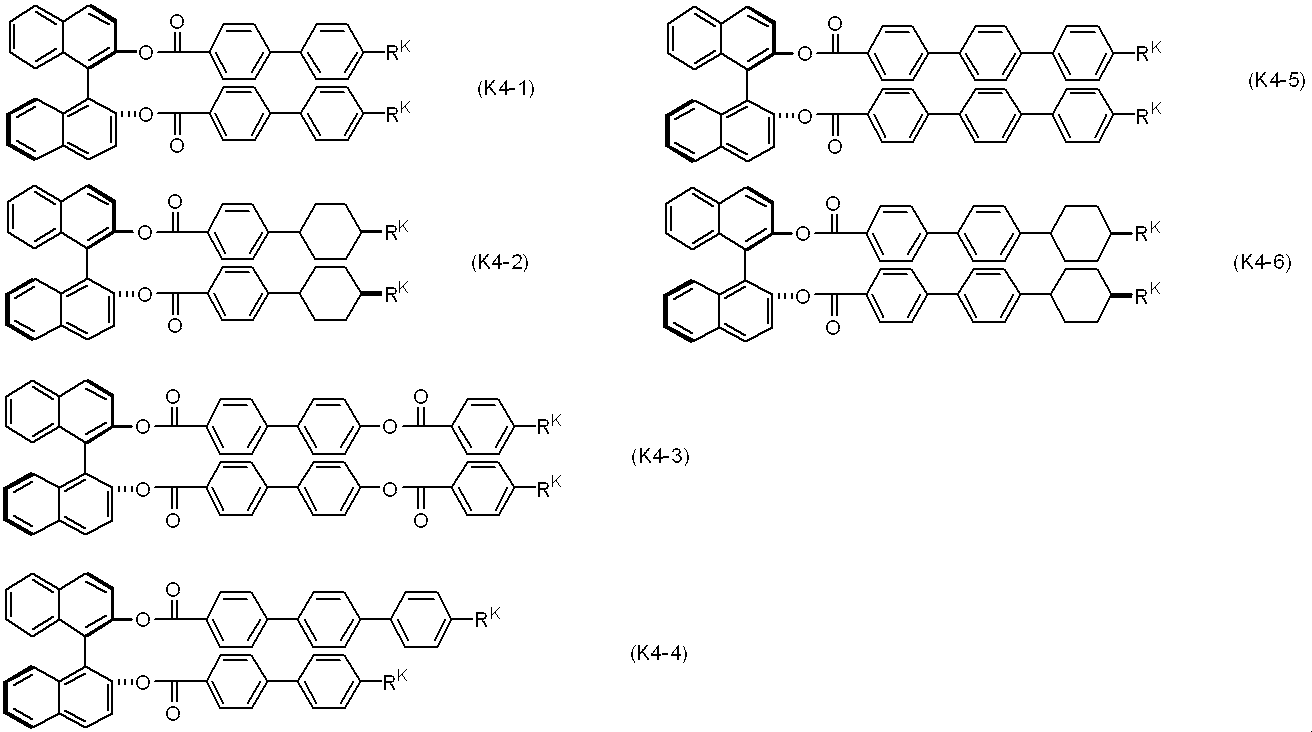

(これらの式中、RKは独立して、炭素数3~10のアルキルであり、このアルキル中の環に隣接する-CH2-は-O-で置き換えられてもよく、任意の-CH2-は、-CH=CH-で置き換えられてもよい。) [34]
The liquid crystal composition according to any one of claims 31 to 33, wherein the chiral agent comprises at least one compound selected from the group of compounds represented by formulas (K1) to (K5).
(In the formula (K1) ~ (K5), R K is independently hydrogen, halogen, -C≡N, alkyl having -N = C = O, -N = C = S or C 1-20 In this alkyl, any —CH 2 — is replaced by —O—, —S—, —COO—, —OCO—, —CH═CH—, —CF═CF— or —C≡C—. Any hydrogen in the alkyl may be replaced by halogen, and the terminal —CH 3 is
May be replaced by;
A is independently an aromatic or non-aromatic 3- to 8-membered ring or a condensed ring having 9 or more carbon atoms, and any hydrogen in these rings is halogen, alkyl having 1 to 3 carbon atoms Or may be replaced by haloalkyl, the ring —CH 2 — may be replaced by —O—, —S— or —NH—, —CH═ may be replaced by —N═; Independently, hydrogen, halogen, alkyl having 1 to 3 carbon atoms, haloalkyl having 1 to 3 carbon atoms, aromatic or non-aromatic 3 to 8 membered ring, or condensed ring having 9 or more carbon atoms Any hydrogen in these rings may be replaced by halogen, alkyl of 1 to 3 carbon atoms or haloalkyl, —CH 2 — may be replaced by —O—, —S— or —NH—, -CH = may be replaced by -N =; Z is independent A single bond and alkylene having 1 to 8 carbon atoms, but arbitrary —CH 2 — is —O—, —S—, —COO—, —OCO—, —CSO—, —OCS—, — N = N—, —CH═N—, —N═CH—, —CH═CH—, —CF═CF— or —C≡C— may be substituted, and any hydrogen is replaced by halogen. Well;
X is a single bond, —COO—, —OCO—, —CH 2 O—, —OCH 2 —, —CF 2 O—, —OCF 2 —, or —CH 2 CH 2 —;
mK is an integer of 1 to 4. )
[35]
The chiral agent is selected from the group of compounds represented by formulas (K2-1) to (K2-8), (K4-1) to (K4-6), and (K5-1) to (K5-3), respectively. The liquid crystal composition according to any one of claims 31 to 33, comprising at least one selected compound.
(In these formulas, R K is independently alkyl having 3 to 10 carbon atoms, and —CH 2 — adjacent to the ring in this alkyl may be replaced by —O—, and any —CH 2 — 2 — may be replaced by —CH═CH—.
“Arbitrary” indicates that not only the position but also the number is arbitrary, but the case where the number is 0 is not included. The expression that any A may be replaced by B, C, or D is in addition to any A being replaced by B, any A being replaced by C, and any A being replaced by D. Thus, it is meant to include the case where a plurality of A are replaced by at least two of B to D. For example, alkyl in which any —CH 2 — may be replaced by —O— or —CH═CH— includes alkyl, alkenyl, alkoxy, alkoxyalkyl, alkoxyalkenyl, alkenyloxyalkyl, and the like. In the present invention, it is not preferable that two consecutive —CH 2 — are replaced with —O— to give —O—O—. Further, it is not preferable that —CH 2 — at the terminal in alkyl is replaced with —O—. The present invention is further described below. Preferred examples of the terminal group, ring, bonding group and the like in the compound represented by the formula (1) are also described.
本発明の光学的に等方性の液晶相で駆動される光素子は、使用できる広い温度範囲、短い応答時間、大きなコントラスト比、および低い駆動電圧を有する。
The liquid crystal composition of the present invention exhibits stability against heat, light, etc., a high upper limit temperature and a lower lower limit temperature of an optically isotropic liquid crystal phase, and is low in an element driven with an optically isotropic liquid crystal phase. It has a driving voltage. The polymer / liquid crystal composite material of the present invention having an optically isotropic liquid crystal phase exhibits a high maximum temperature and a low minimum temperature of the optically isotropic liquid crystal phase, and is optically isotropic. The element driven in the liquid crystal phase has a low driving voltage.
The optical element driven by the optically isotropic liquid crystal phase of the present invention has a wide usable temperature range, a short response time, a large contrast ratio, and a low driving voltage.
本発明の光学的に等方性の液晶相を有する液晶組成物は、アキラル成分Tおよびキラル剤を含有し、アキラル成分Tは前記式(1)で表される化合物を成分Aとして含む。本発明の第1の態様は、アキラル成分Tが、この成分Aのみの組成物、成分Aと前記式(2)で表される成分Bを含有する組成物、成分Aと本明細書中で特に成分名を示していないその他の成分を含有する組成物、または成分Aおよび成分Bと本明細書中で特に成分名を示していないその他の成分を含有する組成物である。本発明の液晶組成物は、アキラル成分Tとして本発明の式(1)で表される化合物の少なくとも1種類を0.1~100重量%の割合で含有することが、優良な特性を発現せしめるために好ましい。 1-1 Compound (1)
The liquid crystal composition having an optically isotropic liquid crystal phase of the present invention contains an achiral component T and a chiral agent, and the achiral component T contains a compound represented by the formula (1) as component A. In the first aspect of the present invention, the achiral component T is a composition containing only component A, a composition containing component A and component B represented by the formula (2), component A and the present specification. It is a composition containing the other component which does not show the component name in particular, or a composition containing the component A and the component B and the other component which does not show the component name in particular in this specification. The liquid crystal composition of the present invention contains at least one compound represented by the formula (1) of the present invention as the achiral component T in a proportion of 0.1 to 100% by weight, and exhibits excellent characteristics. Therefore, it is preferable.

式(1)において、R1は水素または炭素数1~20のアルキルであり、このアルキル中の任意の-CH2-は、-O-、-S-、-COO-、-OCO-、-CH=CH-、-CF=CF-または-C≡C-で置き換えられてもよく、このアルキル中およびアルキル中の任意の-CH2-が、-O-、-S-、-COO-、-OCO-、-CH=CH-、-CF=CF-または-C≡C-で置き換えられた基中の任意の水素はハロゲンまたは炭素数1~3のアルキルで置き換えられてもよく、;Z1、Z2、およびZ3は独立して、単結合、-COO-または-CF2O-であるが、少なくとも一つは-CF2O-であり、;L1、L2、L3、L4、およびL5は独立して、水素またはフッ素であり;X1は水素、ハロゲン、-SF5、または炭素数1~10のアルキルであり、このアルキルにおいて任意の-CH2-は、-O-、-S-、-CH=CH-、または-C≡C-により置き換えられてもよく、そしてアルキル中およびアルキル中の任意の-CH2-が、-O-、-S-、-CH=CH-、または-C≡C-で置き換えられた基中の任意の水素はフッ素により置き換えられてもよい。 The compound represented by formula (1) will be described.
In the formula (1), R 1 is hydrogen or alkyl having 1 to 20 carbon atoms, and any —CH 2 — in the alkyl is —O—, —S—, —COO—, —OCO—, — CH═CH—, —CF═CF— or —C≡C— may be substituted, and any —CH 2 — in the alkyl and in the alkyl is —O—, —S—, —COO—, Any hydrogen in the group replaced by —OCO—, —CH═CH—, —CF═CF— or —C≡C— may be replaced by halogen or alkyl of 1 to 3 carbons; 1 , Z 2 and Z 3 are independently a single bond, —COO— or —CF 2 O—, but at least one is —CF 2 O—; L 1 , L 2 , L 3 , L 4, and L 5 are independently hydrogen or fluorine; X 1 is hydrogen, halo Emissions, alkyl of -SF 5 or 1 to 10 carbon atoms, any -CH 2 - in the alkyl may, -O -, - S -, - replaced by CH = CH-, or -C≡C- And any hydrogen in a group in which any —CH 2 — in the alkyl and in alkyl is replaced by —O—, —S—, —CH═CH—, or —C≡C— May be replaced by fluorine.


これらの式において、R1は式(CHN-1)~(CHN-19)のいずれか1つで表される構造であり、R1aは水素または炭素数1~20のアルキルであり、;L1、L2、L3、L4、およびL5は独立して、水素またはフッ素であり、;X1はフッ素、塩素、、-CF3、-CHF2、-OCF3、-OCHF2、-C≡C-CF3、-CH=CHCF3、-OCF2CFHCF3である。 In the formula (1), the structures represented by the formulas (1-1) to (1-3) are preferable.
In these formulas, R 1 is a structure represented by any one of formulas (CHN-1) to (CHN-19), R 1a is hydrogen or alkyl having 1 to 20 carbons; 1, L 2, L 3, L 4, and L 5 are independently hydrogen or fluorine,; X 1 is fluorine, chlorine ,, - CF 3, -CHF 2, -OCF 3, -OCHF 2, —C≡C—CF 3 , —CH═CHCF 3 , —OCF 2 CFHCF 3 .
本発明に用いられる化合物(1)をさらに詳細に説明する。化合物(1)は4個のベンゼン環と少なくとも1個の-CF2O-連結基を有する化合物である。この化合物は、素子が通常使用される条件下において物理的および化学的に極めて安定であり、そして他の液晶化合物との相溶性がよい。この化合物を含有する組成物は素子が通常使用される条件下で安定である。したがって組成物において光学的に等方性の液晶相の温度範囲を広げることが可能となり、幅広い温度範囲で表示素子として使用することができる。さらにこの化合物は誘電率異方性と屈折率異方性が大きい為、光学的に等方性の液晶相で駆動される組成物の駆動電圧を下げるための成分として有用である。 1-2 Properties of Compound (1) The compound (1) used in the present invention will be described in more detail. Compound (1) is a compound having four benzene rings and at least one —CF 2 O— linking group. This compound is extremely physically and chemically stable under the conditions in which the device is normally used, and has good compatibility with other liquid crystal compounds. A composition containing this compound is stable under conditions in which the device is normally used. Therefore, the temperature range of the optically isotropic liquid crystal phase in the composition can be expanded, and the composition can be used as a display element in a wide temperature range. Furthermore, since this compound has a large dielectric anisotropy and refractive index anisotropy, it is useful as a component for lowering the driving voltage of a composition driven with an optically isotropic liquid crystal phase.
化合物(1)の好ましい例は、式(1-1)~(1-3)である。より好ましい例として、式(1-2A)~(1-2H)、(1-3A)~(1-3C)を挙げることができる。さらに好ましい例として式(1-2A)~(1-2D)、(1-3A)、(1-3B)を挙げることができる。最も好ましい例として、式(1-2A)および(1-2C)を挙げることができる。 1-3 Specific Examples of Compound (1) Preferred examples of the compound (1) are the formulas (1-1) to (1-3). More preferred examples include formulas (1-2A) to (1-2H) and (1-3A) to (1-3C). More preferred examples include formulas (1-2A) to (1-2D), (1-3A), and (1-3B). The most preferred examples include formulas (1-2A) and (1-2C).


次に、化合物(1)の合成について説明する。化合物(1)は有機合成化学における手法を適切に組み合わせることにより合成できる。出発物に目的の末端基、環および結合基を導入する方法は、オーガニックシンセシス(Organic Syntheses, John Wiley & Sons, Inc)、オーガニック・リアクションズ(Organic Reactions, John Wiley & Sons, Inc)、コンプリヘンシブ・オーガニック・シンセシス(Comprehensive Organic Synthesis, Pergamon Press)、新実験化学講座(丸善)などに記載されている。 1-4 Synthesis of Compound (1) Next, the synthesis of compound (1) will be described. Compound (1) can be synthesized by appropriately combining techniques in organic synthetic chemistry. Methods for introducing the desired end groups, rings and linking groups into the starting materials are Organic Syntheses (John Wiley & Sons, Inc), Organic Reactions (John Wiley & Sons, Inc), Comprehensive・ It is described in the organic synthesis (Comprehensive Organic Synthesis, Pergamon Press), new experimental chemistry course (Maruzen).
化合物(1)における結合基Z1~Z3を生成する方法の一例は、下記のスキームの通りである。このスキームにおいて、MSG1またはMSG2は少なくとも一つの環を有する1価の有機基である。スキームで用いた複数のMSG1(またはMSG2)は、同一であってもよいし、または異なってもよい。化合物(1A)~(1J)は、化合物(1)に相当する。

アリールホウ酸(20)と公知の方法で合成される化合物(21)とを、炭酸塩水溶液とテトラキス(トリフェニルホスフィン)パラジウムのような触媒の存在下で反応させて化合物(1A)を合成する。この化合物(1A)は、公知の方法で合成される化合物(22)にn-ブチルリチウムを、次いで塩化亜鉛を反応させ、ジクロロビス(トリフェニルホスフィン)パラジウムのような触媒の存在下で化合物(21)を反応させることによっても合成される。 (I) Formation of a single bond A compound obtained by reacting an arylboric acid (20) with a compound (21) synthesized by a known method in the presence of a catalyst such as an aqueous carbonate solution and tetrakis (triphenylphosphine) palladium. Synthesize (1A). This compound (1A) is prepared by reacting compound (22) synthesized by a known method with n-butyllithium and then with zinc chloride, and in the presence of a catalyst such as dichlorobis (triphenylphosphine) palladium. ) Is also reacted.
化合物(22)にn-ブチルリチウムを、続いて二酸化炭素を反応させてカルボン酸(23)を得る。化合物(23)と、公知の方法で合成されるフェノール(24)とをDCC(1,3-ジシクロヘキシルカルボジイミド)とDMAP(4-ジメチルアミノピリジン)の存在下で脱水させて-COO-を有する化合物(1B)を合成する。この方法によって-OCO-を有する化合物も合成する。 (II) Formation of —COO— and —OCO— The compound (22) is reacted with n-butyllithium and subsequently with carbon dioxide to obtain a carboxylic acid (23). Compound (23) and phenol (24) synthesized by a known method are dehydrated in the presence of DCC (1,3-dicyclohexylcarbodiimide) and DMAP (4-dimethylaminopyridine) to have -COO- Synthesize (1B). A compound having —OCO— is also synthesized by this method.
化合物(1B)をローソン試薬のような硫黄化剤で処理して化合物(25)を得る。化合物(25)をフッ化水素ピリジン錯体とNBS(N-ブロモスクシンイミド)でフッ素化し、-CF2O-を有する化合物(1C)を合成する。M. Kuroboshi et al., Chem. Lett., 1992,827.を参照。化合物(1C)は化合物(25)を(ジエチルアミノ)サルファートリフルオリド(DAST)でフッ素化しても合成される。W. H. Bunnelle et al., J. Org. Chem. 1990, 55, 768.を参照。この方法によって-OCF2-を有する化合物も合成する。Peer. Kirsch et al., Angew. Chem. Int. Ed. 2001, 40, 1480.に記載の方法によってこれらの結合基を生成させることも可能である。 (III) Formation of —CF 2 O— and —OCF 2 — Compound (1B) is treated with a sulfurizing agent such as Lawesson's reagent to obtain compound (25). The compound (25) is fluorinated with a hydrogen fluoride pyridine complex and NBS (N-bromosuccinimide) to synthesize a compound (1C) having —CF 2 O—. See M. Kuroboshi et al., Chem. Lett., 1992, 827. Compound (1C) can also be synthesized by fluorinating compound (25) with (diethylamino) sulfur trifluoride (DAST). See W. H. Bunnelle et al., J. Org. Chem. 1990, 55, 768. A compound having —OCF 2 — is also synthesized by this method. These linking groups can also be generated by the method described in Peer. Kirsch et al., Angew. Chem. Int. Ed. 2001, 40, 1480.
式(1)で表される化合物を合成する方法は複数あり、市販の試薬から適宜、本明細書実施例や文献、書籍を参考にして合成することが可能である。
1-4-5 化合物(2)を合成する方法
式(2)で表される化合物を合成する方法は複数あり、市販の試薬から適宜、本明細書実施例や文献、書籍を参考にして合成することが可能である。また、同一出願人の特願2008-236049を参考にして合成することが可能である。 1-4-4 Method for Synthesizing Compound (1) There are a plurality of methods for synthesizing the compound represented by the formula (1). Is possible.
1-4-5 Method for Synthesizing Compound (2) There are a plurality of methods for synthesizing the compound represented by formula (2). Is possible. Further, it can be synthesized with reference to Japanese Patent Application No. 2008-236049 of the same applicant.
本発明の第2の態様は、前記式(1)で表される化合物からなる成分Aに以下に示す成分B、C、DおよびEから選ばれた成分を加えることにより得られるアキラル成分T及びキラル剤を含有する液晶組成物であり、アキラル成分Tが成分Aのみの組成物に比べて、駆動電圧、液晶相温度範囲、屈折率異方性値、誘電率異方性値および粘度等を自由に調整することができる。 2 Compounds (2) to (18)
The second aspect of the present invention is an achiral component T obtained by adding a component selected from components B, C, D and E shown below to component A consisting of the compound represented by formula (1). It is a liquid crystal composition containing a chiral agent, and has a driving voltage, a liquid crystal phase temperature range, a refractive index anisotropy value, a dielectric anisotropy value, a viscosity and the like as compared with a composition in which an achiral component T is only component A. It can be adjusted freely.
さらに式(12)、(13)および(14)からなる群から選ばれた少なくとも1種の化合物からなる成分Fを混合することによりしきい値電圧、液晶相温度範囲、屈折率異方性値、誘電率異方性値および粘度等を調整することができる。
また、成分Aに加える成分として、前記式(15)、(16)、(17)からなる群から選ばれた少なくとも1種の化合物からなる成分G、または前記式(18)からなる群から選ばれた少なくとも1種の化合物からなる成分Hが好ましい。成分GおよびHは特に屈折率異方性値、誘電率異方性値を大きくするために有用である。 As a component to be added to component A, at least one component B selected from the group consisting of at least one compound selected from the group of the above formula (2) and the above formulas (3), (4) and (5) is selected. Component C consisting of a kind of compound, or Component D consisting of at least one compound selected from the group consisting of the above formula (6), or the above formulas (7), (8), (9), (10), What mixed the component E which consists of an at least 1 sort (s) of compound chosen from the group which consists of (11) is preferable.
Further, by mixing the component F consisting of at least one compound selected from the group consisting of the formulas (12), (13) and (14), threshold voltage, liquid crystal phase temperature range, refractive index anisotropy value In addition, the dielectric anisotropy value and viscosity can be adjusted.
In addition, the component added to component A is selected from the component G consisting of at least one compound selected from the group consisting of the formulas (15), (16) and (17), or the group consisting of the formula (18). Component H consisting of at least one compound selected is preferred. Components G and H are particularly useful for increasing the refractive index anisotropy value and the dielectric anisotropy value.

(式中、R2、X2は式(2)におけるR2、X2と同じ意味を表す)
Of the above component B, preferred examples of the compound represented by formula (2) include formulas (2-1) to (2-9).
(Wherein, R 2, X 2 represents the same meaning as R 2, X 2 in the formula (2))


(式中、R3、X3は式(3)~(5)におけるR3、X3と同じ意味を表す)
(Wherein, R 3, X 3 has the same meaning as R 3, X 3 in the formula (3) to (5))
前記、式(6)で表される化合物すなわち成分Dのうちの好適例として、式(6-1)~(6-62)を挙げることができる。 These compounds represented by the formulas (3) to (5), that is, the component C, have a positive dielectric anisotropy value and are extremely excellent in thermal stability and chemical stability. It is used when preparing a liquid crystal composition. The content of component C in the liquid crystal composition of the present invention is suitably in the range of 1 to 99% by weight, preferably 1 to 60% by weight, more preferably 1 to 35% by weight, based on the total weight of the liquid crystal composition. It is. Further, the viscosity can be adjusted by further containing a compound (component F) represented by the formulas (12) to (14).
Preferred examples of the compound represented by formula (6), that is, component D include formulas (6-1) to (6-62).


(これらの式において、R4およびX4は式(6)におけるR4、X4と同じ意味である)
(In these formulas, R 4 and X 4 are the same meaning as R 4, X 4 in the formula (6))

(式中、R5,R6は式(7)~(11)におけるR5、R6と同じ意味を表す)
(Wherein, R 5, R 6 has the same meaning as R 5, R 6 in the formula (7) to (11))


(式中、R7およびR8は式(12)~(14)におけるR7、R8と同じ意味を表す)
(Wherein, R 7 and R 8 are as defined R 7, R 8 in the formula (12) to (14))
本発明の第3の態様は、成分Aに以下に示す成分GおよびHから選ばれた成分を加えることにより得られる液晶組成物である。 3 Compounds (15) to (19)
A third aspect of the present invention is a liquid crystal composition obtained by adding a component selected from components G and H shown below to component A.


(式中、R9、X5は式(15)~(18)におけるR9、X5と同じ意味を表し、(F)は水素またはフッ素を表し、(F,Cl)は水素またはフッ素または塩素を表す。)
(Wherein, R 9, X 5 has the same meaning as R 9, X 5 in the formula (15) ~ (18), (F) denotes hydrogen or fluorine, (F, Cl) is hydrogen or fluorine or Represents chlorine.)


(これらの式において、R10、X6は、式(19)におけるR10、X6と同じ意味であり、(F)は水素またはフッ素を表し、(F,Cl)は水素またはフッ素または塩素を表す。)
(In these formulas, R 10 and X 6 have the same meanings as R 10 and X 6 in formula (19), (F) represents hydrogen or fluorine, and (F, Cl) represents hydrogen, fluorine or chlorine. Represents.)
4.1 光学的に等方性の液晶相を有する組成物の組成
本発明の第4の態様は、式(1)で表される化合物およびキラル剤を含む組成物であり、光学的に等方性の液晶相で駆動される光素子に用いることのできる液晶組成物である。液晶組成物は、光学的等方性の液晶相を発現する組成物である。
式(1)で表される化合物は、4環化合物である割には透明点が低く、大きな誘電率異方性と大きな屈折率異方性を有するため、その含有量は、キラル剤が添加されていないアキラル成分Tの全重量に対して、0.1~100重量%の割合で含有することが、優良な特性を発現せしめるために好ましい。その含有量は、より好ましくは5~100重量%、より好ましくは30~100重量%、さらに好ましくは70~100重量%である。
さらに式(1-2)で表される化合物は、他の液晶組成物との相溶性に優れるため、その含有量はアキラル成分Tの全重量に対して、5~100重量%でもよく、好ましくは20~100重量%、より好ましくは20~80重量%である。
本発明の液晶組成物の全重量に対して、キラル剤を1~40重量%含むことが好ましく、3~25重量%含むことがさらに好ましく、5~15重量%含むことが最も好ましい。これらの範囲でキラル剤を含有する液晶組成物は、光学的に等方性の液晶相を有するようになりやすく、好ましい。
液晶組成物に含有されるキラル剤は1種でも2種以上でもよい。 4 Composition having optically isotropic liquid crystal phase
4.1 Composition of Composition Having Optically Isotropic Liquid Crystal Phase A fourth aspect of the present invention is a composition comprising a compound represented by formula (1) and a chiral agent, and is optically equivalent. It is a liquid crystal composition that can be used for an optical element driven in a isotropic liquid crystal phase. The liquid crystal composition is a composition that exhibits an optically isotropic liquid crystal phase.
The compound represented by the formula (1) has a low clearing point for a tetracyclic compound and has a large dielectric anisotropy and a large refractive index anisotropy. The content of 0.1 to 100% by weight with respect to the total weight of the achiral component T that has not been formed is preferable in order to develop excellent characteristics. The content is more preferably 5 to 100% by weight, more preferably 30 to 100% by weight, and still more preferably 70 to 100% by weight.
Furthermore, since the compound represented by the formula (1-2) is excellent in compatibility with other liquid crystal compositions, the content thereof may be 5 to 100% by weight with respect to the total weight of the achiral component T, preferably Is 20 to 100% by weight, more preferably 20 to 80% by weight.
The chiral agent is preferably contained in an amount of 1 to 40% by weight, more preferably 3 to 25% by weight, and most preferably 5 to 15% by weight based on the total weight of the liquid crystal composition of the present invention. A liquid crystal composition containing a chiral agent in these ranges is preferable because it tends to have an optically isotropic liquid crystal phase.
The chiral agent contained in the liquid crystal composition may be one type or two or more types.
光学的に等方性の液晶組成物が含有するキラル剤としては、アキラル成分Tに添加した時に、液晶組成物にねじれを生じさせる光学活性な化合物であれば、特に限定されない。キラル剤としては、ねじり力(Helical Twisting Power)が大きい化合物が好ましい。ねじり力が大きい化合物は所望のピッチを得るために必要な添加量が少なくできるので、駆動電圧の上昇を抑えられ、実用上有利である。具体的には、下記式(K1)~(K5)で表される化合物が好ましい。 4.2 Chiral Agent The chiral agent contained in the optically isotropic liquid crystal composition is not particularly limited as long as it is an optically active compound that causes twisting in the liquid crystal composition when added to the achiral component T. . As the chiral agent, a compound having a large twisting power is preferable. A compound having a large torsional force can reduce the amount of addition necessary for obtaining a desired pitch, and therefore, an increase in driving voltage can be suppressed, which is practically advantageous. Specifically, compounds represented by the following formulas (K1) to (K5) are preferable.

で置き換えられてもよく;
Aは独立して、芳香族性あるいは非芳香族性の3~8員環、または、炭素数9以上の縮合環であり、これらの環の任意の水素がハロゲン、炭素数1~3のアルキルまたはハロアルキルで置き換えられてもよく、環の-CH2-は-O-、-S-または-NH-で置き換えられてもよく、-CH=は-N=で置き換えられてもよく;Bは独立して、水素、ハロゲン、炭素数1~3のアルキル、炭素数1~3のハロアルキル、芳香族性または非芳香族性の3から8員環、または、炭素数9以上の縮合環であり、これらの環の任意の水素がハロゲン、炭素数1~3のアルキルまたはハロアルキルで置き換えられてもよく、-CH2-は-O-、-S-または-NH-で置き換えられてもよく、-CH=は-N=で置き換えられてもよく;Zは独立して、単結合、炭素数1~8のアルキレンであるが、任意の-CH2-は、-O-、-S-、-COO-、-OCO-、-CSO-、-OCS-、-N=N-、-CH=N-、-N=CH-、-CH=CH-、-CF=CF-または-C≡C-で置き換えられてもよく、任意の水素はハロゲンで置き換えられてもよく;
Xは単結合、-COO-、-OCO-、-CH2O-、-OCH2-、-CF2O-、-OCF2-、または-CH2CH2-であり;
mKは1~4の整数である。なお、RK、A、Z、mKが2つ以上ある場合には、それらは同一でも異なっていてもよい。
May be replaced by;
A is independently an aromatic or non-aromatic 3- to 8-membered ring or a condensed ring having 9 or more carbon atoms, and any hydrogen in these rings is halogen, alkyl having 1 to 3 carbon atoms Or may be replaced by haloalkyl, the ring —CH 2 — may be replaced by —O—, —S— or —NH—, —CH═ may be replaced by —N═; Independently, hydrogen, halogen, alkyl having 1 to 3 carbon atoms, haloalkyl having 1 to 3 carbon atoms, aromatic or non-aromatic 3 to 8 membered ring, or condensed ring having 9 or more carbon atoms Any hydrogen in these rings may be replaced by halogen, alkyl of 1 to 3 carbon atoms or haloalkyl, —CH 2 — may be replaced by —O—, —S— or —NH—, -CH = may be replaced by -N =; Z is independent A single bond and alkylene having 1 to 8 carbon atoms, but arbitrary —CH 2 — is —O—, —S—, —COO—, —OCO—, —CSO—, —OCS—, — N = N—, —CH═N—, —N═CH—, —CH═CH—, —CF═CF— or —C≡C— may be substituted, and any hydrogen is replaced by halogen. Well;
X is a single bond, —COO—, —OCO—, —CH 2 O—, —OCH 2 —, —CF 2 O—, —OCF 2 —, or —CH 2 CH 2 —;
mK is an integer of 1 to 4. In addition, when there are two or more R K , A, Z, and mK, they may be the same or different.


(式中、RKは独立に、炭素数3~10のアルキルであり、このアルキル中の環に隣接する-CH2-は-O-で置き換えられてもよく、アルキル中またはアルキル中の環に隣接する-CH2-が-O-で置き換えられた基中の任意の-CH2-は、-CH=CH-で置き換えられてもよい。)。
(Wherein R K is independently alkyl having 3 to 10 carbon atoms, and —CH 2 — adjacent to the ring in this alkyl may be replaced by —O—, and the ring in alkyl or in alkyl is Any —CH 2 — in the group in which —CH 2 — adjacent to is replaced by —O— may be replaced by —CH═CH—.
液晶組成物が光学的に等方性を有するとは、巨視的には液晶分子配列は等方的であるため光学的に等方性を示すが、微視的には液晶秩序が存在することをいう。「液晶組成物が微視的に有する液晶秩序に基づくピッチ(以下では、ピッチと呼ぶことがある)」は700nm以下であることが好ましく、500nm以下であることがさらに好ましく、350nm以下であることが最も好ましい。 4.3 The optically isotropic liquid crystal phase liquid crystal composition is optically isotropic. Although the liquid crystal molecular alignment is isotropic macroscopically, it is optically isotropic. Microscopically, it means that liquid crystal order exists. “Pitch based on microscopic order of liquid crystal composition (hereinafter, sometimes referred to as pitch)” is preferably 700 nm or less, more preferably 500 nm or less, and 350 nm or less. Is most preferred.
光学的に等方性の液晶相が二色以上の回折光を示さない状態とは、ブルー相I、ブルー相IIに観測されるプレートレット組織が観測されず、概ね一面単色であることを意味する。二色以上の回折光を示さない光学的に等方性の液晶相では、色の明暗が面内で均一であることまでは不要である。 In general, blue phases are classified into three types (blue phase I, blue phase II, blue phase III), and these three types of blue phases are all optically active and isotropic. In the blue phase I or blue phase II, two or more types of diffracted light caused by Bragg reflection from different lattice planes are observed. The blue phase is generally observed between the non-liquid crystal isotropic phase and the chiral nematic phase.
The state in which the optically isotropic liquid crystal phase does not show two or more colors of diffracted light means that the platelet structure observed in the blue phase I and the blue phase II is not observed and is generally monochromatic. To do. In an optically isotropic liquid crystal phase that does not show diffracted light of two or more colors, it is not necessary until the brightness of the color is uniform in the plane.
また、可視光の光を反射する液晶材料では、表示素子として利用する場合に色味が問題となることがあるが、二色以上の回折光を示さない液晶では、反射波長が低波長シフトするため、狭義のブルー相(プレートレット組織を発現する相)より長いピッチで可視光の反射を消失させることができる。 An optically isotropic liquid crystal phase that does not show diffracted light of two or more colors has an advantage that the reflected light intensity due to Bragg reflection can be suppressed or shifted to the lower wavelength side.
In addition, the liquid crystal material that reflects visible light may have a problem of color when used as a display element. However, in a liquid crystal that does not exhibit diffracted light of two or more colors, the reflection wavelength is shifted by a low wavelength. Therefore, the reflection of visible light can be eliminated at a pitch longer than the narrowly defined blue phase (phase that expresses the platelet structure).

光学的に等方性の液晶相における電気複屈折はピッチが長くなるほど大きくなるので、その他の光学特性(透過率、回折波長など)の要求を満たす限り、キラル剤の種類と含有量を調整して、ピッチを長く設定することにより、電気複屈折を大きくすることができる。 When an electric field is applied to the liquid crystal medium of the present invention in an optically isotropic liquid crystal phase, electric birefringence occurs, but the Kerr effect is not necessarily required.
Since the electrical birefringence in the optically isotropic liquid crystal phase increases as the pitch increases, the type and content of the chiral agent are adjusted as long as the requirements of other optical properties (transmittance, diffraction wavelength, etc.) are satisfied. Thus, the electric birefringence can be increased by setting the pitch long.
本発明の光学的に等方性の液晶組成物は、その組成物の特性に影響を与えない範囲で、さらに高分子物質等の他の化合物が添加されてもよい。本発明の液晶組成物は、高分子物質の他にも、たとえば二色性色素、フォトクロミック化合物を含有していてもよい。二色性色素の例としては、メロシアニン系、スチリル系、アゾ系、アゾメチン系、アゾキシ系、キノフタロン系、アントラキノン系、テトラジン系などが挙げられる。 4.4 Other Components The optically isotropic liquid crystal composition of the present invention may be further added with other compounds such as a polymer substance as long as the properties of the composition are not affected. The liquid crystal composition of the present invention may contain, for example, a dichroic dye and a photochromic compound in addition to the polymer substance. Examples of dichroic dyes include merocyanine, styryl, azo, azomethine, azoxy, quinophthalone, anthraquinone, and tetrazine.
本発明の第5の態様は、式(1)で表される化合物およびキラル剤を含む液晶組成物と高分子の複合材料であり、光学的に等方性を示すものである。光学的に等方性の液晶相で駆動される光素子に用いることのできる光学的に等方性の高分子/液晶複合材料である。このような高分子/液晶複合材料は例えば、項[1]~[33]に記載の液晶組成物と高分子で構成される。
本発明の、「高分子/液晶複合材料」とは、液晶材料と高分子の化合物の両者を含む複合材料であれば特に限定されないが、高分子の一部または全部が液晶材料に溶解していない状態で高分子が液晶材料と相分離している状態でもよい。なお、本明細書において、特に言及がなければ、ネマチック相はキラルネマチック相を含まない、狭義のネマチック相を意味する。 5). Optically Isotropic Polymer / Liquid Crystal Composite Material A fifth aspect of the present invention is a composite material of a liquid crystal composition and a polymer containing a compound represented by formula (1) and a chiral agent, and optically Isotropic. This is an optically isotropic polymer / liquid crystal composite material that can be used in an optical element driven in an optically isotropic liquid crystal phase. Such a polymer / liquid crystal composite material includes, for example, the liquid crystal composition described in the items [1] to [33] and a polymer.
The “polymer / liquid crystal composite material” of the present invention is not particularly limited as long as it is a composite material containing both a liquid crystal material and a polymer compound, but part or all of the polymer is dissolved in the liquid crystal material. The polymer may be phase-separated from the liquid crystal material in the absence of the liquid crystal material. In the present specification, unless otherwise specified, a nematic phase means a nematic phase in a narrow sense that does not include a chiral nematic phase.
本発明の複合材料は、光学的に等方性の液晶組成物と、予め重合されて得られた高分子とを混合しても製造できるが、高分子の材料となる低分子量のモノマー、マクロモノマー、オリゴマー等(以下、まとめて「モノマー等」という)と液晶組成物CLCとを混合してから、当該混合物において重合反応を行うことによって、製造されることが好ましい。モノマー等と液晶組成物とを含む混合物を本件明細書では、「重合性モノマー/液晶混合物」と呼ぶ。「重合性モノマー/液晶混合物」には必要に応じて、後述する重合開始剤、硬化剤、触媒、安定剤、二色性色素、またはフォトクロミック化合物等を、本発明の効果を損なわない範囲で含んでもよい。たとえば、本件発明の重合性モノマー/液晶混合物には必要に応じて、重合開始剤を重合性モノマー100重量部に対して0.1~20重量部含有してもよい。 5.2 Polymer The composite material of the present invention can be produced by mixing an optically isotropic liquid crystal composition and a polymer obtained by polymerization in advance. It is preferably produced by mixing a monomer having a molecular weight, a macromonomer, an oligomer or the like (hereinafter collectively referred to as “monomer or the like”) and the liquid crystal composition CLC, and then performing a polymerization reaction in the mixture. In the present specification, a mixture containing a monomer or the like and a liquid crystal composition is referred to as a “polymerizable monomer / liquid crystal mixture”. The “polymerizable monomer / liquid crystal mixture” includes a polymerization initiator, a curing agent, a catalyst, a stabilizer, a dichroic dye, or a photochromic compound, which will be described later, as necessary, as long as the effects of the present invention are not impaired. But you can. For example, the polymerizable monomer / liquid crystal mixture of the present invention may contain a polymerization initiator in an amount of 0.1 to 20 parts by weight based on 100 parts by weight of the polymerizable monomer, if necessary.
また、好適な複合材料を得るためには、高分子はメソゲン部位を有するものが好ましく、高分子の原料モノマーとしてメソゲン部位を有する原料モノマーをその一部に、あるいは全部に用いることができる。 As the polymer raw material constituting the composite material of the present invention, for example, a low molecular weight monomer, macromonomer, and oligomer can be used. In this specification, the high molecular weight raw material monomer is a low molecular weight monomer, macromonomer. , Used to include oligomers. In addition, it is preferable that the obtained polymer has a three-dimensional cross-linked structure, and therefore, it is preferable to use a polyfunctional monomer having two or more polymerizable functional groups as a raw material monomer for the polymer. The polymerizable functional group is not particularly limited, and an acrylic group, a methacryl group, a glycidyl group, an epoxy group, an oxetanyl group, a vinyl group, and the like can be raised, but an acrylic group and a methacryl group are preferable from the viewpoint of polymerization rate. When a monomer having two or more polymerizable functional groups in the polymer raw material monomer is contained in an amount of 10% by weight or more, high transparency and isotropy are easily exhibited in the composite material of the present invention. This is preferable.
In order to obtain a suitable composite material, the polymer preferably has a mesogen moiety, and a raw material monomer having a mesogen moiety can be used as a part or all of the raw material monomer.
メソゲン部位を有する単官能性、または二官能性モノマーは構造上特に限定されないが、例えば下記の式(M1)または式(M2)で表される化合物を挙げることができる。 5.2.1 Monofunctional / bifunctional monomer having a mesogen moiety The monofunctional or bifunctional monomer having a mesogen moiety is not particularly limited in terms of structure. For example, the following formula (M1) or (M2) The compound represented by these can be mentioned.
Rb-Y-(AM-ZM)m1-AM-Y-Rb (M2)

R b —Y— (A M —Z M ) m1 —A M —Y—R b (M2)
また、式(M3-2)、式(M3-3)、式(M3-4)、式(M3-7)はラジカル重合で重合するのが好適である。式(M3-1)、式(M3-5)、式(M3-6)はカチオン重合で重合するのが好適である。いずれもリビング重合なので、少量のラジカルあるいはカチオン活性種が反応系内に発生すれば重合は開始する。活性種の発生を加速する目的で重合開始剤を使用できる。活性種の発生には例えば光または熱を使用できる。 Here, R d in formulas (M3-1) to (M3-7) is each independently hydrogen, halogen, or alkyl having 1 to 5 carbon atoms, and in these alkyls, arbitrary hydrogen is replaced by halogen. May be. Preferred R d is hydrogen, halogen and methyl. Particularly preferred R d is hydrogen, fluorine and methyl.
In addition, the formula (M3-2), the formula (M3-3), the formula (M3-4), and the formula (M3-7) are preferably polymerized by radical polymerization. The formulas (M3-1), (M3-5), and (M3-6) are preferably polymerized by cationic polymerization. Since both are living polymerizations, the polymerization starts when a small amount of radicals or cationic active species are generated in the reaction system. A polymerization initiator can be used for the purpose of accelerating the generation of active species. For example, light or heat can be used to generate the active species.
化合物の安定性を考慮して、酸素と酸素とが隣接した-CH2-O-O-CH2-よりも、酸素と酸素とが隣接しない-CH2-O-CH2-O-の方が好ましい。硫黄においても同様である。 In formulas (M1) and (M2), A M is each independently an aromatic or non-aromatic 5-membered ring, 6-membered ring, or condensed ring having 9 or more carbon atoms. CH 2 — may be —O—, —S—, —NH—, or —NCH 3 —, and —CH═ in the ring may be replaced by —N═, the hydrogen atom on the ring is halogen, and carbon number It may be replaced with 1 to 5 alkyls or alkyl halides. Specific examples of preferred A M are 1,4-cyclohexylene, 1,4-cyclohexenylene, 1,4-phenylene, naphthalene-2,6-diyl, tetrahydronaphthalene-2,6-diyl, fluorene -2, 7-diyl or bicyclo [2.2.2] octane-1,4-diyl, and in these rings, any —CH 2 — may be replaced by —O—, and any —CH═ is Any hydrogen in these rings and in any of these rings in which any —CH═ is replaced by —N═ may be halogen, alkyl having 1 to 5 carbons or 1 carbon. May be replaced by ˜5 alkyl halides.
In consideration of the stability of the compound, —CH 2 —O—CH 2 —O— in which oxygen and oxygen are not adjacent to each other than —CH 2 —O—O—CH 2 — in which oxygen and oxygen are adjacent to each other Is preferred. The same applies to sulfur.
2-フルオロ-1,4-フェニレンは、3-フルオロ-1,4-フェニレンと構造的に同一であるので、後者は例示しなかった。この規則は、2,5-ジフルオロ-1,4-フェニレンと3,6-ジフルオロ-1,4-フェニレンの関係などにも適用される。 Among these, particularly preferred A M, 1,4-cyclohexylene, 1,4-cyclohexenylene, 1,4-phenylene, 2-fluoro-1,4-phenylene, 2,3-difluoro-1,4 -Phenylene, 2,5-difluoro-1,4-phenylene, 2,6-difluoro-1,4-phenylene, 2-methyl-1,4-phenylene, 2-trifluoromethyl-1,4-phenylene, 2 , 3-bis (trifluoromethyl) -1,4-phenylene, naphthalene-2,6-diyl, tetrahydronaphthalene-2,6-diyl, fluorene-2,7-diyl, 9-methylfluorene-2,7- Diyl, 1,3-dioxane-2,5-diyl, pyridine-2,5-diyl, and pyrimidine-2,5-diyl. The configuration of 1,4-cyclohexylene and 1,3-dioxane-2,5-diyl is preferably trans rather than cis.
Since 2-fluoro-1,4-phenylene is structurally identical to 3-fluoro-1,4-phenylene, the latter was not exemplified. This rule also applies to the relationship between 2,5-difluoro-1,4-phenylene and 3,6-difluoro-1,4-phenylene.


For the purpose of optimizing the optical isotropy of the polymer / liquid crystal composite material of the present invention, a monomer having a mesogenic moiety and having three or more polymerizable functional groups may be used. As the monomer having a mesogenic moiety and having three or more polymerizable functional groups, known compounds can be suitably used. Examples thereof include (M4-1) to (M4-3), and more specific examples include: Examples thereof include compounds described in JP 2000-327632 A, JP 2004-182949 A, and JP 2004-59777 A. However, in (M4-1) to (M4-3), R b , Za, Y, and (F) have the same meaning as described above.

メソゲン部位を有さない重合性のある官能基を持つモノマーとして、例えば、炭素数1~30の直鎖あるいは分岐アクリレート、炭素数1~30の直鎖あるいは分岐ジアクリレート、三つ以上の重合性官能基を有するモノマーとしては、グリセロール・プロポキシレート(1PO/OH)トリアクリレート、ペンタエリスリトール・プロポキシレート・トリアクリレート、ペンタエリスリトール・トリアクリレート、トリメチロールプロパン・エトキシレート・トリアクリレート、トリメチロールプロパン・プロポキシレート・トリアクリレート、トリメチロールプロパン・トリアクリレート、ジ(トリメチロールプロパン)テトラアクリレート、ペンタエリスリトール・テトラアクリレート、ジ(ペンタエリスリトール)ペンタアクリレート、ジ(ペンタエリスリトール)ヘキサアクリレート、トリメチロールプロパン・トリアクリレートなどを挙げることができるが、これらに限定されるものではない。 5.2.2 Monomer having a polymerizable functional group not having a mesogen moiety As a monomer having a polymerizable functional group not having a mesogen moiety, for example, a linear or branched acrylate having 1 to 30 carbon atoms C 1-30 linear or branched diacrylates, monomers having three or more polymerizable functional groups include glycerol propoxylate (1PO / OH) triacrylate, pentaerythritol propoxylate triacrylate, penta Erythritol triacrylate, trimethylolpropane ethoxylate triacrylate, trimethylolpropane propoxylate triacrylate, trimethylolpropane triacrylate, di (trimethylolpropane) tetraacrylate, pentaerythritol Examples thereof include, but are not limited to, tetraacrylate, di (pentaerythritol) pentaacrylate, di (pentaerythritol) hexaacrylate, and trimethylolpropane triacrylate.
本発明の複合材料を構成する高分子の製造における重合反応は特に限定されず、例えば、光ラジカル重合、熱ラジカル重合、光カチオン重合等が行われる。 5.2.3 Polymerization initiator The polymerization reaction in the production of the polymer constituting the composite material of the present invention is not particularly limited, and for example, photoradical polymerization, thermal radical polymerization, photocationic polymerization and the like are performed.
IB)、ジt-ブチルパーオキシド(DTBPO)、アゾビスイソブチロニトリル(AIBN)、アゾビスシクロヘキサンカルボニトリル(ACN)などである。 Examples of preferred initiators for thermal radical polymerization that can be used in thermal radical polymerization are benzoyl peroxide, diisopropyl peroxydicarbonate, t-butylperoxy-2-ethylhexanoate, t-butylperoxypivalate , T-butylperoxydiisobutyrate, lauroyl peroxide, dimethyl 2,2′-azobisisobutyrate (MA
IB), di-t-butyl peroxide (DTBPO), azobisisobutyronitrile (AIBN), azobiscyclohexanecarbonitrile (ACN) and the like.
本発明の複合材料を構成する高分子の製造において、前記モノマー等および重合開始剤の他にさらに1種または2種以上の他の好適な成分、例えば、硬化剤、触媒、安定剤等を加えてもよい。 5.2.4 Curing agent and the like In the production of the polymer constituting the composite material of the present invention, in addition to the monomer and the polymerization initiator, one or more other suitable components, for example, a curing agent Catalysts, stabilizers and the like may be added.
本発明の高分子/液晶複合材料中における液晶組成物の含有率は、複合材料が光学的に等方性の液晶相を発現できる範囲であれば、可能な限り高含有率であることが好ましい。液晶組成物の含有率が高い方が、本発明の複合材料の電気複屈折値が大きくなるからである。 5.3 Content Ratio of Liquid Crystal Composition, etc. The content ratio of the liquid crystal composition in the polymer / liquid crystal composite material of the present invention is possible as long as the composite material can express an optically isotropic liquid crystal phase. It is preferable that the content is as high as possible. This is because the electric birefringence value of the composite material of the present invention increases as the content of the liquid crystal composition is higher.
本発明の高分子/液晶複合材料は、たとえば二色性色素、フォトクロミック化合物を本発明の効果を損なわない範囲で含有していてもよい。
以下、実施例により本発明をさらに詳しく説明するが、本発明はこれら実施例によっては制限されない。なお特に断りのない限り、「%」は「重量%」を意味する。 5.4 Other Components The polymer / liquid crystal composite material of the present invention may contain, for example, a dichroic dye and a photochromic compound as long as the effects of the present invention are not impaired.
EXAMPLES Hereinafter, although an Example demonstrates this invention further in detail, this invention is not restrict | limited by these Examples. Unless otherwise specified, “%” means “% by weight”.
本発明の第6の態様は、液晶組成物または高分子/液晶複合材料(以下では、本発明の液晶組成物および高分子/液晶複合材料を総称して液晶媒体と呼ぶことがある)を含む光学的に等方性の液晶相で駆動される光素子である。
電界無印加時には液晶媒体は光学的に等方性であるが、電場を印加すると、液晶媒体は光学的異方性を生じ、電界による光変調が可能となる。
液晶表示素子の構造例としては、図1に示すように、櫛型電極基板の電極が、左側から伸びる電極1と右側から伸びる電極2が交互に配置された構造を挙げることができる。電極1と電極2との間に電位差がある場合、図1に示すような櫛型電極基板上では、上方向と下方向の2つの方向の電界が存在する状態を提供できる。
6 Optical Device A sixth aspect of the present invention is a liquid crystal composition or a polymer / liquid crystal composite material (hereinafter, the liquid crystal composition and polymer / liquid crystal composite material of the present invention may be collectively referred to as a liquid crystal medium). ) Including an optically isotropic liquid crystal phase.
When no electric field is applied, the liquid crystal medium is optically isotropic, but when an electric field is applied, the liquid crystal medium exhibits optical anisotropy, and light modulation by the electric field becomes possible.
As an example of the structure of the liquid crystal display element, as shown in FIG. 1, there can be mentioned a structure in which electrodes of a comb-shaped electrode substrate are alternately arranged with electrodes 1 extending from the left side and electrodes 2 extending from the right side. When there is a potential difference between the electrode 1 and the electrode 2, it is possible to provide a state in which an electric field exists in two directions, an upper direction and a lower direction, on the comb-shaped electrode substrate as shown in FIG.
記録計としては島津製作所製のC-R6A型Chromatopac、またはその同等品を用いた。得られたガスクロマトグラムには、成分化合物に対応するピークの保持時間およびピークの面積値が示されている。 The sample was dissolved in toluene to prepare a 1% by weight solution, and 1 μl of the resulting solution was injected into the sample vaporization chamber.
As a recorder, a C-R6A type Chromatopac manufactured by Shimadzu Corporation or an equivalent thereof was used. The obtained gas chromatogram shows the peak retention time and peak area value corresponding to the component compounds.
液晶化合物の物性値を測定する試料としては、化合物そのものを試料とする場合、化合物を母液晶と混合して試料とする場合の2種類がある。 Samples for Measuring Physical Property Values of Liquid Crystal Compounds There are two types of samples for measuring the physical property values of liquid crystal compounds: when the compound itself is used as a sample, and when the compound is mixed with mother liquid crystals as a sample.
母液晶A:

Mother liquid crystal A:
物性値の測定は後述する方法で行った。これら測定方法の多くは、日本電子機械工業会規格(Standard of Electric Industries Association of Japan)EIAJ・ED-2521Aに記載された方法、またはこれを修飾した方法である。また、測定に用いたTN素子には、TFTを取り付けなかった。 Method for measuring physical property values of liquid crystal compounds, etc. The physical property values were measured by the method described later. Many of these measuring methods are the methods described in the Standard of Electric Industries Association of Japan EIAJ / ED-2521A or a modified method thereof. Moreover, TFT was not attached to the TN element used for the measurement.
(1)偏光顕微鏡を備えた融点測定装置のホットプレート(メトラー社FP-52型ホットステージ)に化合物を置き、3℃/分の速度で加熱しながら相状態とその変化を偏光顕微鏡で観察し、液晶相の種類を特定した。
(2)パーキンエルマー社製走査熱量計DSC-7システム、またはDiamond DSCシステムを用いて、3℃/分速度で昇降温し、試料の相変化に伴う吸熱ピーク、または発熱ピークの開始点を外挿により求め(on set)、相転移温度を決定した。 Phase structure and phase transition temperature (° C.): Measurement was performed by the following methods (1) and (2).
(1) A compound is placed on a hot plate (Mettler FP-52 type hot stage) of a melting point measuring apparatus equipped with a polarizing microscope, and a phase state and its change are observed with a polarizing microscope while heating at a rate of 3 ° C./min. , Identified the type of liquid crystal phase.
(2) Using a scanning calorimeter DSC-7 system or Diamond DSC system manufactured by PerkinElmer, Inc., the temperature is raised and lowered at a rate of 3 ° C / min, and the start point of the endothermic peak or exothermic peak accompanying the phase change of the sample is excluded. The phase transition temperature was determined by onset.
ピッチ長は選択反射を用いて測定した(液晶便覧196頁 2000年発行、丸善)。選択反射波長λには、関係式<n>p/λ=1が成立する。ここで<n>は平均屈折率を表し、次式で与えられる。<n>={(n∥ 2+n⊥ 2)/2}1/2。選択反射波長は顕微分光光度計(日本電子(株)、商品名MSV-350)で測定した。得られた反射波長を平均屈折率で除すことにより、ピッチを求めた。可視光より長波長領域に反射波長を有するコレステリック液晶のピッチは、光学活性化合物濃度が低い領域では光学活性化合物の濃度の逆数に比例することから、可視光領域に選択反射波長を有する液晶のピッチ長を数点測定し、直線外挿法により求めた。「光学活性化合物」は本発明におけるキラル剤に相当する。
Pitch (P; measured at 25 ° C .; nm)
The pitch length was measured using selective reflection (Liquid Crystal Manual 196 pages 2000, Maruzen). For the selective reflection wavelength λ, the relational expression <n> p / λ = 1 holds. Here, <n> represents an average refractive index and is given by the following equation. <n> = {(n ∥ 2 + n ⊥ 2) / 2} 1/2. The selective reflection wavelength was measured with a microspectrophotometer (JEOL Ltd., trade name MSV-350). The pitch was obtained by dividing the obtained reflection wavelength by the average refractive index. The pitch of cholesteric liquid crystals having a reflection wavelength in the longer wavelength region than visible light is proportional to the reciprocal of the concentration of the optically active compound in the region where the optically active compound concentration is low. The length was measured at several points and determined by a linear extrapolation method. The “optically active compound” corresponds to the chiral agent in the present invention.
式(S1-8)の合成

合成スキームを下図に示す。

Synthesis of formula (S1-8)
The synthesis scheme is shown in the figure below.
窒素雰囲気下の反応器へ、(S1-1)88.3gと触媒7.54g、テトラヒドロフラン(THF)900ml加え、これに室温で、2mol/LのブチルマグネシウムクロリドのTHF溶液を滴下し、4時間還流した。反応液を室温まで冷却し、これにトルエンを加え、これを1N-塩酸、水で洗浄した。硫酸マグネシウムで乾燥した後、減圧にて溶媒を留去した。ヘプタンを展開溶媒として、シリカゲルカラムクロマトグラフィーにより精製し、減圧にて乾燥して(S1-2)75.7gを得た。このものの(S1-1)からの収率は93.1%であった。 Synthesis of Compound (S1-2) To a reactor under a nitrogen atmosphere, 88.3 g of (S1-1), 7.54 g of catalyst and 900 ml of tetrahydrofuran (THF) were added, and 2 mol / L of butylmagnesium chloride was added to this at room temperature. The THF solution was added dropwise and refluxed for 4 hours. The reaction solution was cooled to room temperature, toluene was added thereto, and this was washed with 1N hydrochloric acid and water. After drying with magnesium sulfate, the solvent was distilled off under reduced pressure. The product was purified by silica gel column chromatography using heptane as a developing solvent and dried under reduced pressure to obtain 75.7 g (S1-2). The yield based on (S1-1) was 93.1%.
窒素雰囲気下の反応器へ、(S1-2)を55.5g、テトラヒドロフラン(THF)550mlを加え、-70℃まで冷却し、これにn-BuLi(1.55M;n-ヘキサン溶液)161mlを滴下し、1時間そのままの温度で撹拌した。反応液にヨウ素63.4gのTHF450ml溶液を-70℃で滴下し、そのままの温度で5時間撹拌した。反応液を室温まで加温し、チオ硫酸ナトリウム水溶液に注いだ。生成物を酢酸エチルで抽出し、有機層をチオ硫酸ナトリウム水、水で洗浄した。硫酸マグネシウムで乾燥した後、減圧にて溶媒を留去した。ヘプタン/トルエン=3/1を展開溶媒として、シリカゲルカラムクロマトグラフィーにより精製し、減圧にて乾燥して(S1-3)79.1gを得た。このものの(S1-2)からの収率は97.5%であった。 Synthesis of Compound (S1-3) To a reactor under a nitrogen atmosphere, 55.5 g of (S1-2) and 550 ml of tetrahydrofuran (THF) were added and cooled to −70 ° C., to which n-BuLi (1.55 M ; N-hexane solution) was added dropwise and stirred at the same temperature for 1 hour. A solution of 63.4 g of iodine in 450 ml of THF was added dropwise to the reaction solution at −70 ° C., and the mixture was stirred at the same temperature for 5 hours. The reaction was warmed to room temperature and poured into aqueous sodium thiosulfate. The product was extracted with ethyl acetate, and the organic layer was washed with aqueous sodium thiosulfate and water. After drying with magnesium sulfate, the solvent was distilled off under reduced pressure. The product was purified by silica gel column chromatography using heptane / toluene = 3/1 as a developing solvent, and dried under reduced pressure to obtain 79.1 g (S1-3). The yield based on (S1-2) was 97.5%.
窒素雰囲気下の反応器へ、(S1-3)79.1g、3,5-ジフロオロフェニルボロン酸(S1-4)38.4g、テトラキストリフェニルホスフィンパラジウム3.5gと炭酸ナトリウム70.9gとトルエン/エタノール/水=3/3/1(容積比)の混合溶媒560ml加え、7時間還流した。反応液を室温まで冷却し、これにトルエンを加え、これを1N-塩酸、水で洗浄した。硫酸マグネシウムで乾燥した後、減圧にて溶媒を留去した。ヘプタンを展開溶媒として、シリカゲルカラムクロマトグラフィーにより精製し、減圧にて乾燥し、残分をエタノール/酢酸エチル=4/1で再結晶して、(S1-5)50.6gを得た。このものの(S1-3)からの収率は66.2%であった。 Synthesis of Compound (S1-5) To a reactor under a nitrogen atmosphere, 79.1 g of (S1-3), 38.4 g of 3,5-difluorophenylboronic acid (S1-4), tetrakistriphenylphosphine palladium 3 0.5 g, 70.9 g of sodium carbonate and 560 ml of a mixed solvent of toluene / ethanol / water = 3/3/1 (volume ratio) were added and refluxed for 7 hours. The reaction solution was cooled to room temperature, toluene was added thereto, and this was washed with 1N hydrochloric acid and water. After drying with magnesium sulfate, the solvent was distilled off under reduced pressure. The product was purified by silica gel column chromatography using heptane as a developing solvent, dried under reduced pressure, and the residue was recrystallized with ethanol / ethyl acetate = 4/1 to obtain 50.6 g of (S1-5). The yield based on (S1-3) was 66.2%.
窒素雰囲気下の反応器へ、化合物(S1-5) 15.0gとTHF 150mlとを加えて、-74℃まで冷却した。そこへ、1.60M n-ブチルリチウム,n-ヘキサン溶液 27.4mlを-74℃から-60℃の温度範囲で滴下し、さらに60分攪拌した。続いてジブロモジフルオロメタン 12.6gのTHF 20.0ml溶液を-75℃から-70℃の温度範囲で滴下し、25℃に戻しつつ60分攪拌した。得られた反応混合物を氷水 150mlに注ぎ込み、混合した。トルエン 100mlを加え有機層と水層とに分離させ抽出操作を行い得られた有機層を分取し、続いて食塩水で洗浄して、無水硫酸マグネシウムで乾燥した。得られた溶液を、減圧下で濃縮し、残渣をヘプタンを展開溶媒とし、シリカゲルカラムクロマトグラフィーによる分取操作で精製した。溶媒を留去し乾燥させ、(S1-6)16.5gを得た。 Synthesis of Compound (S1-6) 15.0 g of Compound (S1-5) and 150 ml of THF were added to a reactor under a nitrogen atmosphere and cooled to -74 ° C. Thereto, 27.4 ml of a 1.60 M n-butyllithium / n-hexane solution was added dropwise in the temperature range of −74 ° C. to −60 ° C., and the mixture was further stirred for 60 minutes. Subsequently, a solution of 12.6 g of dibromodifluoromethane in 20.0 ml of THF was dropped in a temperature range of −75 ° C. to −70 ° C. and stirred for 60 minutes while returning to 25 ° C. The obtained reaction mixture was poured into 150 ml of ice water and mixed. Toluene (100 ml) was added to separate the organic layer from the aqueous layer and extraction was performed. The resulting organic layer was separated, washed with brine, and dried over anhydrous magnesium sulfate. The obtained solution was concentrated under reduced pressure, and the residue was purified by a fractionation operation by silica gel column chromatography using heptane as a developing solvent. The solvent was distilled off and dried to obtain 16.5 g of (S1-6).
窒素雰囲気下の反応器へ、化合物(S1-6) 6.0g、3,4,5-トリフルオロフェノール(S1-7) 1.4g、炭酸カリウム 2.8g、N,N-ジメチルホルムアミド(DMF) 100mlを加え、90℃で120分攪拌した。反応混合物を25℃に戻した後、氷水 50mlに注ぎ込み混合させ、トルエン 100mlを加え有機層と水層とに分離させ抽出操作を行い得られた有機層を分取し、続いて飽和炭酸水素ナトリウム水溶液、0.5N水酸化ナトリウム水溶液、食塩水で順次洗浄して、無水硫酸マグネシウムで乾燥した。得られた溶液を、減圧下で濃縮し、残渣をヘプタンを展開溶媒とし、シリカゲルカラムクロマトグラフィーによる分取操作で精製した。さらにヘプタン/ソルミックスA-11の混合溶媒からの再結晶により精製し、乾燥させ、(S1-8)1.7gを得た。(S1-8)の(S1-5)からの収率は20.4%であった。 Synthesis of Compound (S1-8) To a reactor under a nitrogen atmosphere, 6.0 g of Compound (S1-6), 1.4 g of 3,4,5-trifluorophenol (S1-7), 2.8 g of potassium carbonate, 100 ml of N, N-dimethylformamide (DMF) was added and stirred at 90 ° C. for 120 minutes. After returning the reaction mixture to 25 ° C., the mixture was poured into 50 ml of ice water and mixed, and 100 ml of toluene was added to separate the organic layer and the aqueous layer, and the organic layer obtained was extracted, followed by saturated sodium bicarbonate. The extract was washed successively with an aqueous solution, a 0.5N aqueous sodium hydroxide solution, and brine and dried over anhydrous magnesium sulfate. The obtained solution was concentrated under reduced pressure, and the residue was purified by a fractionation operation by silica gel column chromatography using heptane as a developing solvent. The product was further purified by recrystallization from a mixed solvent of heptane / Solmix A-11 and dried to obtain 1.7 g of (S1-8). The yield of (S1-8) from (S1-5) was 20.4%.
相転移温度(℃) :K 92.4 N 95.4 I 。 The phase transition temperature of the obtained compound (S1-8) was as follows.
Phase transition temperature (° C.): K 92.4 N 95.4 I.
前述した母液晶Aとして記載された4つの化合物を混合し、ネマチック相を有する母液晶Aを調製した。この母液晶Aの物性は以下のとおりであった。
上限温度(TNI)=71.7℃;誘電率異方性(Δε)=11.0;屈折率異方性(Δn)=0.137。 Physical Properties of Liquid Crystal Compound (S1-8) Four compounds described as the mother liquid crystal A described above were mixed to prepare a mother liquid crystal A having a nematic phase. The physical properties of the mother liquid crystal A were as follows.
Maximum temperature (T NI ) = 71.7 ° C .; dielectric anisotropy (Δ∈) = 11.0; refractive index anisotropy (Δn) = 0.137.
上限温度(TNI)=54.7℃;誘電率異方性(Δε)=54.2;屈折率異方性(Δn)=0.167。
これらのことから液晶化合物(S1-8)は、誘電率異方性(Δε)、屈折率異方性(Δn)の大きい化合物であることがわかった。 A liquid crystal composition B comprising 90% by weight of base liquid crystal A and 10% by weight of (S1-8) obtained in Example 1 was prepared. The physical property value of the obtained liquid crystal composition B was measured, and the extrapolated value of the physical property of the liquid crystal compound (S1-8) was calculated by extrapolating the measured value. The values were as follows:
Maximum temperature (T NI ) = 54.7 ° C .; dielectric anisotropy (Δε) = 54.2; refractive index anisotropy (Δn) = 0.167.
From these results, it was found that the liquid crystal compound (S1-8) was a compound having a large dielectric anisotropy (Δε) and a refractive index anisotropy (Δn).
(S2-1)、(S3-1)、(S4-1)の合成

Synthesis of (S2-1), (S3-1), and (S4-1)
これらの化合物は、合成例1の方法に準じて、適当な試薬を用いることにより合成した。 Synthesis of Compounds (S2-1), (S3-1), and (S4-1) These compounds were synthesized by using an appropriate reagent according to the method of Synthesis Example 1.
前述した母液晶Aとして記載された4つの化合物を混合し、ネマチック相を有する母液晶Aを調製した。この母液晶Aの物性は以下のとおりであった。
上限温度(TNI)=71.7℃;誘電率異方性(Δε)=11.0;屈折率異方性(Δn)=0.137。 Physical Properties of Liquid Crystal Compound (S2-1) Four compounds described as the mother liquid crystal A described above were mixed to prepare a mother liquid crystal A having a nematic phase. The physical properties of the mother liquid crystal A were as follows.
Maximum temperature (T NI ) = 71.7 ° C .; dielectric anisotropy (Δ∈) = 11.0; refractive index anisotropy (Δn) = 0.137.
上限温度(TNI)=61.7℃;誘電率異方性(Δε)=51.1;屈折率異方性(Δn)=0.177。
これらのことから液晶化合物(S2-1)は、誘電率異方性(Δε)、屈折率異方性(Δn)の大きい化合物であることがわかった。 A liquid crystal composition C comprising 90% by weight of base liquid crystal A and 10% by weight of (S2-1) obtained in Synthesis Example 2 was prepared. The physical property value of the obtained liquid crystal composition C was measured, and the extrapolated value of the physical property of the liquid crystal compound (S2-1) was calculated by extrapolating the measured value. The values were as follows:
Maximum temperature (T NI ) = 61.7 ° C .; dielectric anisotropy (Δε) = 51.1; refractive index anisotropy (Δn) = 0.177.
From these results, it was found that the liquid crystal compound (S2-1) was a compound having a large dielectric anisotropy (Δε) and refractive index anisotropy (Δn).
母液晶A 95重量%と、合成例2で得られた(S3-1)の5重量%とからなる液晶組成物Dを調製した。得られた液晶組成物Dの物性値を測定し、測定値を外挿することで液晶化合物(S3-1)の物性の外挿値を算出した。その値は以下のとおりであった。
上限温度(TNI)=55.7℃;誘電率異方性(Δε)=68.1;屈折率異方性(Δn)=0.177。
これらのことから液晶化合物(S3-1)は、誘電率異方性(Δε)が非常に大きな化合物であることがわかった。 A liquid crystal composition D comprising 95% by weight of the mother liquid crystal A of the liquid crystal compound (S3-1) and 5% by weight of (S3-1) obtained in Synthesis Example 2 was prepared. The physical property value of the obtained liquid crystal composition D was measured, and the extrapolated value of the physical property of the liquid crystal compound (S3-1) was calculated by extrapolating the measured value. The values were as follows:
Maximum temperature (T NI ) = 55.7 ° C .; dielectric anisotropy (Δε) = 68.1; refractive index anisotropy (Δn) = 0.177.
From these results, it was found that the liquid crystal compound (S3-1) was a compound having a very large dielectric anisotropy (Δε).
母液晶A 90重量%と、合成例2で得られた(S4-1)の10重量%とからなる液晶組成物Eを調製した。得られた液晶組成物Eの物性値を測定し、測定値を外挿することで液晶化合物(S4-1)の物性の外挿値を算出した。その値は以下のとおりであった。
上限温度(TNI)=59.7℃;誘電率異方性(Δε)=65.9;屈折率異方性(Δn)=0.167。
これらのことから液晶化合物(S4-1)は、誘電率異方性(Δε)が非常に大きな化合物であることがわかった。
(合成例5)
(S5-3)の合成

Maximum temperature (T NI ) = 59.7 ° C .; dielectric anisotropy (Δε) = 65.9; refractive index anisotropy (Δn) = 0.167.
From these results, it was found that the liquid crystal compound (S4-1) was a compound having a very large dielectric anisotropy (Δε).
(Synthesis Example 5)
Synthesis of (S5-3)

化合物(S5-3)の合成
(S1-2)から(S5-1)の合成は、合成例1の(S1-5)から(S1-6)を合成する手法に準じた。この時、(S1-5)に代えて、(S1-2)を用いた。(S5-1)から(S5-3)の合成は、合成例1の(S1-6)から(S1-8)を合成する手法に準じた。この時、(S1-6)に代えて、(S5-1)を用い、(S1-7)に代えて、(S5-2)を用いた。得られた化合物(S5-3)の相転移温度は以下の通りであった。
相転移温度(℃) :K 63.1 N 88.5 I 。 The synthesis scheme is shown in the figure below.
Synthesis of Compound (S5-3) Synthesis from (S1-2) to (S5-1) was in accordance with the method of synthesizing (S1-5) to (S1-6) in Synthesis Example 1. At this time, (S1-2) was used instead of (S1-5). The synthesis of (S5-1) to (S5-3) was in accordance with the method of synthesizing (S1-6) to (S1-8) in Synthesis Example 1. At this time, (S5-1) was used instead of (S1-6), and (S5-2) was used instead of (S1-7). The phase transition temperature of the obtained compound (S5-3) was as follows.
Phase transition temperature (° C.): K 63.1 N 88.5 I.
母液晶A 85重量%と、合成例5で得られた(S5-3)の15重量%とからなる液晶組成物Fを調製した。得られた液晶組成物Fの物性値を測定し、測定値を外挿することで液晶化合物(S5-3)の物性の外挿値を算出した。その値は以下のとおりであった。
上限温度(TNI)=55.7℃;誘電率異方性(Δε)=42.1;屈折率異方性(Δn)=0.164。
これらのことから液晶化合物(S5-3)は、他の液晶化合物との優れた相溶性を有し、誘電率異方性(Δε)、屈折率異方性(Δn)の大きい化合物であることがわかった。
(合成例6)
(S6-1)の合成

Maximum temperature (T NI ) = 55.7 ° C .; dielectric anisotropy (Δε) = 42.1; refractive index anisotropy (Δn) = 0.164.
Therefore, the liquid crystal compound (S5-3) has excellent compatibility with other liquid crystal compounds and has a large dielectric anisotropy (Δε) and refractive index anisotropy (Δn). I understood.
(Synthesis Example 6)
Synthesis of (S6-1)
(S6-1)の合成は、合成例5の(S5-3)を合成する手法に準じた。 Synthesis of Compound (S6-1) Synthesis of (S6-1) was in accordance with the method of synthesizing (S5-3) of Synthesis Example 5.
母液晶A 85重量%と、合成例6で得られた(S6-1)の15重量%とからなる液晶組成物Gを調製した。得られた液晶組成物Gの物性値を測定し、測定値を外挿することで液晶化合物(S6-2)の物性の外挿値を算出した。その値は以下のとおりであった。
上限温度(TNI)=51.0℃;誘電率異方性(Δε)=43.4;屈折率異方性(Δn)=0.164。
これらのことから液晶化合物(S6-1)は、他の液晶化合物との優れた相溶性を有し、誘電率異方性(Δε)、屈折率異方性(Δn)の大きい化合物であることがわかった。
A liquid crystal composition G comprising 85% by weight of the base liquid crystal A of the liquid crystal compound (S6-1) and 15% by weight of (S6-1) obtained in Synthesis Example 6 was prepared. The physical property value of the obtained liquid crystal composition G was measured, and the extrapolated value of the physical property of the liquid crystal compound (S6-2) was calculated by extrapolating the measured value. The values were as follows:
Maximum temperature (T NI ) = 51.0 ° C .; dielectric anisotropy (Δε) = 43.4; refractive index anisotropy (Δn) = 0.164.
For these reasons, the liquid crystal compound (S6-1) has excellent compatibility with other liquid crystal compounds and has a large dielectric anisotropy (Δε) and refractive index anisotropy (Δn). I understood.
本発明において、液晶組成物の特性値の測定は下記の方法にしたがって行うことができる。それらの多くは、日本電子機械工業会規格(Standard of Electric Industries Association of Japan)EIAJ・ED-2521Aに記載された方法、またはこれを修飾した方法である。測定に用いたTN素子には、TFTを取り付けなかった。 (Composition of the present invention)
In the present invention, the characteristic value of the liquid crystal composition can be measured according to the following method. Many of them are the methods described in the Standard of Electric Industries Association of Japan EIAJ ED-2521A or a modified method thereof. No TFT was attached to the TN device used for measurement.
1)誘電率異方性が正である試料:測定はM. Imai et al., Molecular Crystals and Liquid Crystals, Vol. 259, 37 (1995) に記載された方法に従った。ツイスト角が0°であり、そして2枚のガラス基板の間隔(セルギャップ)が5μmであるTN素子に試料を入れた。TN素子に16ボルトから19.5ボルトの範囲で0.5ボルト毎に段階的に印加した。0.2秒の無印加のあと、ただ1つの矩形波(矩形パルス;0.2秒)と無印加(2秒)の条件で印加を繰り返した。この印加によって発生した過渡電流(transient current)のピーク電流(peak current)とピーク時間(peak time)を測定した。これらの測定値とM. Imaiらの論文の40頁の計算式(8)とから回転粘度の値を得た。この計算で必要な誘電率異方性の値は、この回転粘度の測定で使用した素子にて、下記の誘電率異方性の測定方法で求めた。 Rotational viscosity (γ1; measured at 25 ° C .; mPa · s):
1) Sample having positive dielectric anisotropy: Measurement was performed according to the method described in M. Imai et al., Molecular Crystals and Liquid Crystals, Vol. 259, 37 (1995). A sample was put in a TN device having a twist angle of 0 ° and a distance (cell gap) between two glass substrates of 5 μm. The voltage was applied to the TN device stepwise in the range of 16 to 19.5 volts every 0.5 volts. After no application for 0.2 seconds, the application was repeated under the condition of only one rectangular wave (rectangular pulse; 0.2 seconds) and no application (2 seconds). The peak current and peak time of the transient current generated by this application were measured. The value of rotational viscosity was obtained from these measured values and the calculation formula (8) on page 40 of the paper by M. Imai et al. The value of dielectric anisotropy necessary for this calculation was obtained by the following dielectric anisotropy measurement method using the element used for the measurement of the rotational viscosity.
1)誘電率異方性が正である組成物:2枚のガラス基板の間隔(ギャップ)が約9μm、ツイスト角が80度の液晶セルに試料を入れた。このセルに20ボルトを印加して、液晶分子の長軸方向における誘電率(ε∥)を測定した。0.5ボルトを印加して、液晶分子の短軸方向における誘電率(ε⊥)を測定した。誘電率異方性の値は、Δε=ε∥-ε⊥、の式から計算した。 Dielectric Anisotropy (Δε; measured at 25 ° C.): When the sample was a compound, the compound was mixed with an appropriate composition, and then the dielectric anisotropy was measured. The dielectric anisotropy of the compound is an extrapolated value.
1) Composition having a positive dielectric anisotropy: A sample was placed in a liquid crystal cell in which the distance (gap) between two glass substrates was about 9 μm and the twist angle was 80 degrees. 20 volts was applied to the cell, and the dielectric constant (ε∥) in the major axis direction of the liquid crystal molecules was measured. 0.5 V was applied, and the dielectric constant (ε⊥) in the minor axis direction of the liquid crystal molecules was measured. The value of dielectric anisotropy was calculated from the equation: Δε = ε∥−ε⊥.
可視光より長波長領域に反射波長を有するコレステリック液晶のピッチは、キラル剤濃度が低い領域ではキラル剤の濃度の逆数に比例することから、可視光領域に選択反射波長を有する液晶のピッチ長を数点測定し、直線外挿法により求めた。 Alternatively, the pitch length was measured using selective reflection (Liquid Crystal Manual 196 (issued in 2000, Maruzen). For the selective reflection wavelength λ, the relational expression <n> p / λ = 1 holds, where <n > Represents the average refractive index and is given by the following equation: <n> = {(n∥ 2 + n⊥ 2 ) / 2} 1/2 The selective reflection wavelength is a microspectrophotometer (JEOL Ltd., product) The pitch was determined by dividing the obtained reflection wavelength by the average refractive index.
The pitch of a cholesteric liquid crystal having a reflection wavelength in the longer wavelength region than visible light is proportional to the reciprocal of the concentration of the chiral agent in a region where the chiral agent concentration is low, so the pitch length of a liquid crystal having a selective reflection wavelength in the visible light region is Several points were measured and obtained by linear extrapolation.
下図に示す液晶化合物を、下記の割合で混合することにより液晶組成物Aを調製した。
構造式の右側に一般式との対応を記した。
液晶組成物A

A liquid crystal composition A was prepared by mixing the liquid crystal compounds shown in the figure below at the following ratio.
The correspondence with the general formula is shown on the right side of the structural formula.
Liquid crystal composition A
なお、ISO-60BA2は、イソソルバイドと4-ヘキシルオキシ安息香酸とをジシクロヘキシルカルボジイミド(DCC)、4-ジメチルアミノピリジン存在下でエステル化することによって得た。
ISO-6OBA2

ISO-60BA2 was obtained by esterifying isosorbide and 4-hexyloxybenzoic acid in the presence of dicyclohexylcarbodiimide (DCC) and 4-dimethylaminopyridine.
ISO-6OBA2
モノマーと液晶組成物の混合物の調製
液晶組成物とモノマーとの混合物として液晶組成物Bを79.4重量%、n-ドデシルアクリレートを10.0重量%、1,4-ジ(4-(6-(アクリロイルオキシ)ヘキシルオキシ)ベンゾイルオキシ)-2-メチルベンゼンを10.0重量%、光重合開始剤として2,2’-ジメトキシフェニルアセトフェノンを0.6重量%混合した液晶組成物C-Mを調製した。 (Example 2)
Preparation of Mixture of Monomer and Liquid Crystal Composition As a mixture of the liquid crystal composition and the monomer, 79.4% by weight of liquid crystal composition B, 10.0% by weight of n-dodecyl acrylate, 1,4-di (4- (6 Liquid crystal composition CM in which 10.0% by weight of (acryloyloxy) hexyloxy) benzoyloxy) -2-methylbenzene and 0.6% by weight of 2,2′-dimethoxyphenylacetophenone as a photopolymerization initiator are mixed Was prepared.
液晶組成物C-Mを配向処理の施されていない櫛型電極基板と対向ガラス基板(非電極付与)の間に狭持し(セル厚10μm)、得られたセルを63.0℃で加熱した。この状態で、紫外光(紫外光強度23mWcm-2(365nm))を1分間照射して、重合反応を行った。 Preparation of polymer / liquid crystal composite material A liquid crystal composition CM was sandwiched between a comb-shaped electrode substrate not subjected to alignment treatment and a counter glass substrate (non-electrode provided) (cell thickness 10 μm), and obtained. The cell was heated at 63.0 ° C. In this state, ultraviolet light (ultraviolet light intensity 23 mWcm −2 (365 nm)) was irradiated for 1 minute to carry out a polymerization reaction.
実施例2で得られた高分子/液晶複合材料C-1Pが狭持されたセルを、図2に示した光学系にセットし、電気光学特性を測定した。光源として偏光顕微鏡(ニコン製 エクリプス LV100POL)の白色光源を用い、セルへの入射角度がセル面に対して垂直となるようにし、櫛型電極の線方向がPolarizerとAnalyzer偏光板に対してそれぞれ45°となるように前記セルを光学系にセットした。測定温度を透明点(59.1℃)-40℃=19.1℃として印加電圧と透過率の関係を調べた。47.6Vの矩形波を印加すると、透過率が80%となり、透過光強度は飽和した。 (Example 3)
The cell sandwiched between the polymer / liquid crystal composite material C-1P obtained in Example 2 was set in the optical system shown in FIG. 2, and the electro-optical characteristics were measured. A white light source of a polarizing microscope (Nikon Eclipse LV100POL) is used as the light source, the incident angle to the cell is perpendicular to the cell surface, and the line direction of the comb-shaped electrode is 45 with respect to the Polarizer and Analyzer polarizer, respectively. The cell was set in the optical system so that the temperature was 0 °. The measurement temperature was the clearing point (59.1 ° C.) − 40 ° C. = 19.1 ° C., and the relationship between the applied voltage and the transmittance was examined. When a rectangular wave of 47.6 V was applied, the transmittance became 80% and the transmitted light intensity was saturated.
下図に示す液晶化合物を、下記の割合で混合することにより液晶組成物Dを調製した。
構造式の右側に一般式との対応を記した。
液晶組成物D

A liquid crystal composition D was prepared by mixing the liquid crystal compounds shown in the figure below at the following ratio.
The correspondence with the general formula is shown on the right side of the structural formula.
Liquid crystal composition D
キラル剤2の構造式

Structural formula of chiral agent 2
モノマーと液晶組成物の混合物の調製
液晶組成物とモノマーとの混合物として液晶組成物Eを87.4重量%、n-ドデシルアクリレートを6.0重量%、1,4-ジ(4-(6-(アクリロイルオキシ)プロピルオキシ)ベンゾイルオキシ)-2-メチルベンゼンを6.0重量%、光重合開始剤として2,2’-ジメトキシフェニルアセトフェノンを0.6重量%混合した液晶組成物F-Mを調製した。 (Example 5)
Preparation of Mixture of Monomer and Liquid Crystal Composition As a mixture of the liquid crystal composition and the monomer, 87.4% by weight of liquid crystal composition E, 6.0% by weight of n-dodecyl acrylate, 1,4-di (4- (6 Liquid crystal composition FM in which 6.0% by weight of (acryloyloxy) propyloxy) benzoyloxy) -2-methylbenzene and 0.6% by weight of 2,2′-dimethoxyphenylacetophenone as a photopolymerization initiator are mixed. Was prepared.
液晶組成物F-Mを配向処理の施されていない櫛型電極基板と対向ガラス基板(非電極付与)の間に狭持し(セル厚10μm)、得られたセルを77.0℃で加熱した。この状態で、紫外光(紫外光強度23mWcm-2(365nm))を1分間照射して、重合反応を行った。 Preparation of polymer / liquid crystal composite material The liquid crystal composition FM was sandwiched between a comb-shaped electrode substrate not subjected to alignment treatment and a counter glass substrate (non-electrode provided) (cell thickness 10 μm), and obtained. The cell was heated at 77.0 ° C. In this state, ultraviolet light (ultraviolet light intensity 23 mWcm −2 (365 nm)) was irradiated for 1 minute to carry out a polymerization reaction.
実施例5で得られた高分子/液晶複合材料F-Pが狭持されたセルを、図2に示した光学系にセットし、電気光学特性を測定した。光源として偏光顕微鏡(ニコン製 エクリプス LV100POL)の白色光源を用い、セルへの入射角度がセル面に対して垂直となるようにし、櫛型電極の線方向がPolarizerとAnalyzer偏光板に対してそれぞれ45°となるように前記セルを光学系にセットした。測定温度を液晶組成物Eの透明点(64.9℃)-25℃=39.9℃とし、印加電圧と透過率の関係を調べた。58Vの矩形波を印加すると、透過率が80%となり、透過光強度は飽和した。
(実施例7)
下図に示す液晶化合物を、上記液晶組成物Dと下記の化合物(16-16a)を85/15の重量比で混合することにより液晶組成物Gを調製した。
化合物(16-16a)

The cell sandwiched with the polymer / liquid crystal composite material FP obtained in Example 5 was set in the optical system shown in FIG. 2, and the electro-optical characteristics were measured. A white light source of a polarizing microscope (Nikon Eclipse LV100POL) is used as the light source, the incident angle to the cell is perpendicular to the cell surface, and the line direction of the comb-shaped electrode is 45 with respect to the Polarizer and Analyzer polarizer, respectively. The cell was set in the optical system so that the temperature was 0 °. The measurement temperature was the clearing point (64.9 ° C.) of liquid crystal composition E−25 ° C. = 39.9 ° C., and the relationship between the applied voltage and the transmittance was examined. When a 58 V rectangular wave was applied, the transmittance was 80% and the transmitted light intensity was saturated.
(Example 7)
A liquid crystal composition G was prepared by mixing the liquid crystal compound shown in the figure below with the above liquid crystal composition D and the following compound (16-16a) in a weight ratio of 85/15.
Compound (16-16a)
モノマーと液晶組成物の混合物の調製
液晶組成物とモノマーとの混合物として液晶組成物Hを87.4重量%、n-ドデシルアクリレートを6.0重量%、1,4-ジ(4-(6-(アクリロイルオキシ)プロピルオキシ)ベンゾイルオキシ)-2-メチルベンゼンを6.0重量%、光重合開始剤として2,2’-ジメトキシフェニルアセトフェノンを0.6重量%混合した液晶組成物I-Mを調製した。 (Example 8)
Preparation of Mixture of Monomer and Liquid Crystal Composition As a mixture of the liquid crystal composition and the monomer, the liquid crystal composition H is 87.4% by weight, n-dodecyl acrylate is 6.0% by weight, 1,4-di (4- (6 Liquid crystal composition IM in which 6.0% by weight of (acryloyloxy) propyloxy) benzoyloxy) -2-methylbenzene and 0.6% by weight of 2,2′-dimethoxyphenylacetophenone as a photopolymerization initiator are mixed. Was prepared.
液晶組成物I-Mを配向処理の施されていない櫛型電極基板と対向ガラス基板(非電極付与)の間に狭持し(セル厚10μm)、得られたセルを60.0℃で加熱した。この状態で、紫外光(紫外光強度23mWcm-2(365nm))を1分間照射して、重合反応を行った。 Preparation of polymer / liquid crystal composite material Liquid crystal composition IM was sandwiched between a comb-shaped electrode substrate not subjected to alignment treatment and a counter glass substrate (non-electrode provided) (cell thickness 10 μm), and obtained. The cell was heated at 60.0 ° C. In this state, ultraviolet light (ultraviolet light intensity 23 mWcm −2 (365 nm)) was irradiated for 1 minute to carry out a polymerization reaction.
実施例8で得られた高分子/液晶複合材料I-Pが狭持されたセルを、図2に示した光学系にセットし、電気光学特性を測定した。光源として偏光顕微鏡(ニコン製 エクリプス LV100POL)の白色光源を用い、セルへの入射角度がセル面に対して垂直となるようにし、櫛型電極の線方向がPolarizerとAnalyzer偏光板に対してそれぞれ45°となるように前記セルを光学系にセットした。測定温度を液晶組成物Hの透明点(57.1℃)-25℃=32.1℃とし、印加電圧と透過率の関係を調べた。58Vの矩形波を印加すると、透過率が80%となり、透過光強度は飽和した。
Example 9
The cell sandwiched with the polymer / liquid crystal composite material IP obtained in Example 8 was set in the optical system shown in FIG. 2, and the electro-optical characteristics were measured. A white light source of a polarizing microscope (Nikon Eclipse LV100POL) is used as the light source, the incident angle to the cell is perpendicular to the cell surface, and the line direction of the comb-shaped electrode is 45 with respect to the Polarizer and Analyzer polarizer, respectively. The cell was set in the optical system so that the temperature was 0 °. The measurement temperature was the clearing point (57.1 ° C.) of liquid crystal composition H−25 ° C. = 32.1 ° C., and the relationship between the applied voltage and the transmittance was examined. When a 58 V rectangular wave was applied, the transmittance was 80% and the transmitted light intensity was saturated.
Claims (47)
- 式(1)で表される化合物を含有するアキラル成分Tおよびキラル剤を含有し、光学的に等方性の液晶相を発現することを特徴とする液晶組成物。
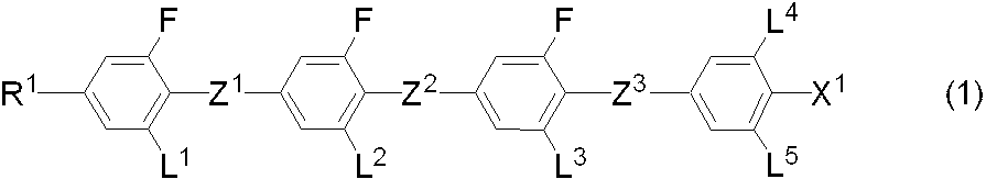
(式(1)において、R1は水素または炭素数1~20のアルキルであり、このアルキル中の任意の-CH2-は、-O-、-S-、-COO-、-OCO-、-CH=CH-、-CF=CF-または-C≡C-で置き換えられてもよく、このアルキル中およびアルキル中の任意の-CH2-が、-O-、-S-、-COO-、-OCO-、-CH=CH-、-CF=CF-または-C≡C-で置き換えられた基中の任意の水素はハロゲンまたは炭素数1~3のアルキルで置き換えられてもよく、;Z1、Z2、およびZ3は独立して、単結合、-COO-または-CF2O-であるが、少なくとも一つは-CF2O-であり、;L1、L2、L3、L4、およびL5は独立して、水素またはフッ素であり;X1は水素、ハロゲン、-SF5、または炭素数1~10のアルキルであり、このアルキルにおいて任意の-CH2-は、-O-、-S-、-CH=CH-、または-C≡C-により置き換えられてもよく、そしてこのアルキル中およびアルキル中の任意の-CH2-が、-O-、-S-、-COO-、-OCO-、-CH=CH-、-CF=CF-または-C≡C-で置き換えられた基中の任意の水素はフッ素により置き換えられてもよい。) A liquid crystal composition comprising an achiral component T containing a compound represented by the formula (1) and a chiral agent and exhibiting an optically isotropic liquid crystal phase.
(In the formula (1), R 1 is hydrogen or alkyl having 1 to 20 carbon atoms, and any —CH 2 — in the alkyl is —O—, —S—, —COO—, —OCO—, —CH═CH—, —CF═CF—, or —C≡C— may be substituted, and any —CH 2 — in the alkyl or alkyl may be replaced by —O—, —S—, —COO—. Any hydrogen in the group replaced by —OCO—, —CH═CH—, —CF═CF— or —C≡C— may be replaced by halogen or alkyl having 1 to 3 carbons; Z 1 , Z 2 , and Z 3 are each independently a single bond, —COO— or —CF 2 O—, but at least one is —CF 2 O—; L 1 , L 2 , L 3, L 4, and L 5 are independently hydrogen or fluorine; X 1 is hydrogen, c Gen, alkyl of -SF 5 or 1 to 10 carbon atoms, any -CH 2 - in the alkyl may, -O -, - S -, - replaced by CH = CH-, or -C≡C- And any —CH 2 — in the alkyl and in the alkyl may be —O—, —S—, —COO—, —OCO—, —CH═CH—, —CF═CF— or — Any hydrogen in the group replaced by C≡C— may be replaced by fluorine.) - 式(1)において、R1が炭素数1~20のアルキル、炭素数2~21のアルケニル、炭素数2~21のアルキニル、炭素数1~19のアルコキシ、炭素数2~20のアルケニルオキシ、炭素数1~19のアルキルチオ、炭素数1~19のアルケニルチオ、または-(CH2)v-CH=CF2であり、ここでvは0または1~19の整数であり;X1が水素、ハロゲン、-SF5、-CH2F、-CHF2、-CF3、-(CH2)2-F、-CF2CH2F、-CF2CHF2、-CH2CF3、-CF2CF3、-(CH2)3-F、-(CF2)3-F、-CF2CHFCF3、-CHFCF2CF3、-(CH2)4-F、-(CF2)4-F、-(CH2)5-F、-(CF2)5-F、-OCH2F、-OCHF2、-OCF3、-O-(CH2)2-F、-OCF2CH2F、-OCF2CHF2、-OCH2CF3、-O-(CH2)3-F、-O-(CF2)3-F、-OCF2CHFCF3、-OCHFCF2CF3、-O(CH2)4-F、-O-(CF2)4-F、-O-(CH2)5-F、-O-(CF2)5-F、-CH=CHF、-CH=CF2、-CF=CHF、-CH=CHCH2F、-CH=CHCF3、-(CH2)2-CH=CF2、-CH2CH=CHCF3、または-CH=CHCF2CF3である請求項1に記載の液晶組成物。 In the formula (1), R 1 is alkyl having 1 to 20 carbon atoms, alkenyl having 2 to 21 carbon atoms, alkynyl having 2 to 21 carbon atoms, alkoxy having 1 to 19 carbon atoms, alkenyloxy having 2 to 20 carbon atoms, Alkylthio having 1 to 19 carbon atoms, alkenylthio having 1 to 19 carbon atoms, or — (CH 2 ) v —CH═CF 2 , where v is 0 or an integer from 1 to 19; X 1 is hydrogen , Halogen, —SF 5 , —CH 2 F, —CHF 2 , —CF 3 , — (CH 2 ) 2 —F, —CF 2 CH 2 F, —CF 2 CHF 2 , —CH 2 CF 3 , —CF 2 CF 3 , — (CH 2 ) 3 —F, — (CF 2 ) 3 —F, —CF 2 CHFCF 3 , —CHFCF 2 CF 3 , — (CH 2 ) 4 —F, — (CF 2 ) 4 — F, - (CH 2) 5 -F, - (CF 2) -F, -OCH 2 F, -OCHF 2 , -OCF 3, -O- (CH 2) 2 -F, -OCF 2 CH 2 F, -OCF 2 CHF 2, -OCH 2 CF 3, -O- ( CH 2 ) 3 —F, —O— (CF 2 ) 3 —F, —OCF 2 CHFCF 3 , —OCHFCF 2 CF 3 , —O (CH 2 ) 4 —F, —O— (CF 2 ) 4 —F , -O- (CH 2) 5 -F , -O- (CF 2) 5 -F, -CH = CHF, -CH = CF 2, -CF = CHF, -CH = CHCH 2 F, -CH = CHCF 3. The liquid crystal composition according to claim 1, wherein the liquid crystal composition is 3 , — (CH 2 ) 2 —CH═CF 2 , —CH 2 CH═CHCF 3 , or —CH═CHCF 2 CF 3 .
- 式(1)において、Z1、Z2、およびZ3が独立して、単結合、または-CF2O-である請求項1または2に記載の液晶組成物。 3. The liquid crystal composition according to claim 1 , wherein in formula (1), Z 1 , Z 2 , and Z 3 are each independently a single bond or —CF 2 O—.
- R1が式(CHN-1)~(CHN-19)のいずれか1つで表される基であり、R1aが水素または炭素数1~20のアルキルである請求項1~3のいずれか1項に記載の液晶組成物。
4. The method according to claim 1, wherein R 1 is a group represented by any one of formulas (CHN-1) to (CHN-19), and R 1a is hydrogen or alkyl having 1 to 20 carbons. 2. A liquid crystal composition according to item 1.
- 式(1-1)~(1-3)のそれぞれで表される化合物の群から選択される少なくとも1つの化合物を含有する請求項1に記載の液晶組成物。

(これらの式において、R1は式(CHN-1)~(CHN-19)のいずれか1つで表される基であり、R1aは水素または炭素数1~20のアルキルであり、;L1、L2、L3、L4およびL5は独立して、水素またはフッ素であり;X1はフッ素、塩素、-CF3、-CHF2、-CH2F、-OCF3、-OCHF2、-OCH2F、-OCF2CFHCF3または-CH=CHCF3である。)
2. The liquid crystal composition according to claim 1, comprising at least one compound selected from the group of compounds represented by formulas (1-1) to (1-3).
(In these formulas, R 1 is a group represented by any one of formulas (CHN-1) to (CHN-19), R 1a is hydrogen or alkyl having 1 to 20 carbons; L 1 , L 2 , L 3 , L 4 and L 5 are independently hydrogen or fluorine; X 1 is fluorine, chlorine, —CF 3 , —CHF 2 , —CH 2 F, —OCF 3 , — OCHF 2 , —OCH 2 F, —OCF 2 CFHCF 3 or —CH═CHCF 3 )
- 式(1-1)~(1-3)において、R1が式(CHN-1)~(CHN-4)および(CHN-6)~(CHN-8)のいずれか1つで表される基であり、R1aは水素または炭素数1~20のアルキルである請求項5に記載の液晶組成物。
In formulas (1-1) to (1-3), R 1 is represented by any one of formulas (CHN-1) to (CHN-4) and (CHN-6) to (CHN-8) 6. The liquid crystal composition according to claim 5, wherein R 1a is hydrogen or alkyl having 1 to 20 carbon atoms.
- アキラル成分Tが、式(2)で表される化合物をさらに含有する請求項1~6のいずれか1項に記載の液晶組成物

(式(2)において、R2は式(CHN-1)~(CHN-4)および(CHN-6)~(CHN-7)のいずれか1つで表される基であり、R1aは水素または炭素数1~20のアルキルであり、;環A1、環A2、環A3、環A4、および環A5は(RG-1)~(RG-13)であり、;Z4、Z5、Z6、Z7、Z8、およびZ9は独立して、単結合または炭素数1~4のアルキレンであり、このアルキレン中の任意の-CH2-は、-O-、-COO-、または-CF2O-に置き換えられてもよく;L6、L7、およびL8は独立して、水素またはフッ素であり;X2はフッ素、塩素、-CF3、-CHF2、-CH2F、-OCF3、-OCHF2、-OCH2F、-OCF2CFHCF3または-CH=CHCF3であり、;l、m、n、o、およびpは独立して、0または1であり、l+m+n+o+p≦4である。)

The liquid crystal composition according to any one of claims 1 to 6, wherein the achiral component T further contains a compound represented by the formula (2).
(In Formula (2), R 2 is a group represented by any one of Formulas (CHN-1) to (CHN-4) and (CHN-6) to (CHN-7)), and R 1a is Hydrogen or alkyl having 1 to 20 carbon atoms; ring A 1 , ring A 2 , ring A 3 , ring A 4 , and ring A 5 are (RG-1) to (RG-13); 4 , Z 5 , Z 6 , Z 7 , Z 8 , and Z 9 are each independently a single bond or alkylene having 1 to 4 carbon atoms, and any —CH 2 — in the alkylene is —O—. , —COO—, or —CF 2 O—; L 6 , L 7 , and L 8 are independently hydrogen or fluorine; X 2 is fluorine, chlorine, —CF 3 , — CHF 2, -CH 2 F, -OCF 3, -OCHF 2, -OCH 2 F, -OCF 2 CFHCF 3 Other is a -CH = CHCF 3,; l, m, n, o, and p are independently 0 or 1, and l + m + n + o + p ≦ 4).
- 式(2)において、R2は水素または炭素数1~20のアルキルであり、このアルキル中の任意の-CH2-は、-O-、-S-、-COO-、-OCO-、-CH=CH-、-CF=CF-または-C≡C-で置き換えられてもよく、このアルキル中およびアルキル中の任意の-CH2-が、-O-、-S-、-COO-、-OCO-、-CH=CH-、-CF=CF-または-C≡C-で置き換えられた基中の任意の水素はハロゲンまたは炭素数1~3のアルキルで置き換えられてもよく、;環A1、環A2、環A3、環A4、および環A5は独立して、ベンゼン環、ナフタレン環、チオフェン環、ピペリジン環、シクロヘキセン環、ビシクロオクタン環、テトラヒドロナフタレン環またはシクロヘキサン環であり、これらの環の任意の水素がハロゲン、炭素数1~3のアルキル、炭素数1~3のアルコキシまたは炭素数1~3のハロゲン化アルキルで置き換えられてもよく、これらの環の-CH2-は-O-または-S-で置き換えられてもよく、-CH=は-N=で置き換えられてもよく;Z4、Z5、Z6、Z7、Z8、およびZ9は独立して、単結合または炭素数1~4のアルキレンであり、このアルキレン中の任意の-CH2-は、-O-、-S-、-COO-、-OCO-、-CSO-、-OCS-、-CH=CH-、-CF=CF-または-C≡C-で置き換えられてもよく、このアルキレン中およびアルキレン中の任意の-CH2-が、-O-、-S-、-COO-、-OCO-、-CSO-、-OCS-、-CH=CH-、-CF=CF-または-C≡C-で置き換えられた基中の任意の水素はハロゲンで置き換えられてもよく;L6、L7、およびL8は独立して、水素またはハロゲンであり;X2は水素、ハロゲン、-C≡N、-N=C=S、-C≡C-C≡N、-SF5、または炭素数1~10のアルキルであり、このアルキルにおいて任意の-CH2-は、-O-、-S-、-CH=CH-、または-C≡C-により置き換えられてもよく、そしてこのアルキル中およびアルキル中の任意の-CH2-が、-O-、-S-、-CH=CH-、または-C≡C-で置き換えられた基中の任意の水素はハロゲンにより置き換えられてもよく;l、m、n、o、およびpは独立して、0または1であり、l+m+n+o+p≦4である、請求項7に記載の液晶組成物。 In the formula (2), R 2 is hydrogen or alkyl having 1 to 20 carbon atoms, and any —CH 2 — in the alkyl is —O—, —S—, —COO—, —OCO—, — CH═CH—, —CF═CF— or —C≡C— may be substituted, and any —CH 2 — in the alkyl and in the alkyl is —O—, —S—, —COO—, Any hydrogen in the group replaced by —OCO—, —CH═CH—, —CF═CF— or —C≡C— may be replaced by halogen or alkyl of 1 to 3 carbon atoms; A 1 , ring A 2 , ring A 3 , ring A 4 , and ring A 5 are independently a benzene ring, naphthalene ring, thiophene ring, piperidine ring, cyclohexene ring, bicyclooctane ring, tetrahydronaphthalene ring or cyclohexane ring. There are these Any hydrogen halogen, alkyl having 1 to 3 carbon atoms, may be replaced by an alkyl halide of the alkoxy or C 1-3 having 1 to 3 carbon atoms, these rings -CH 2 - is -O —CH— may be replaced with —N═; Z 4 , Z 5 , Z 6 , Z 7 , Z 8 , and Z 9 are independently A bond or alkylene having 1 to 4 carbon atoms, and any —CH 2 — in the alkylene is —O—, —S—, —COO—, —OCO—, —CSO—, —OCS—, —CH ═CH—, —CF═CF— or —C≡C— may be substituted, and any —CH 2 — in the alkylene and alkylene may be represented by —O—, —S—, —COO—, — OCO-, -CSO-, -OCS-, -CH = CH-, -CF = C - or any hydrogen in the replaced group by -C≡C- may be replaced by halogen; L 6, L 7, and L 8 are independently hydrogen or halogen; X 2 is hydrogen , Halogen, —C≡N, —N═C═S, —C≡C—C≡N, —SF 5 , or alkyl having 1 to 10 carbons, in which any —CH 2 — is May be replaced by —O—, —S—, —CH═CH—, or —C≡C—, and any —CH 2 — in the alkyl and in the alkyl may be —O—, —S— , —CH═CH—, or any hydrogen in the group replaced with —C≡C— may be replaced by halogen; l, m, n, o, and p are independently 0 or 1 The liquid crystal composition according to claim 7, wherein l + m + n + o + p ≦ 4. .
- 式(2)で表される化合物が2≦l+m+n+o+p≦3であることを特徴とする請求項8に記載の液晶組成物。 The liquid crystal composition according to claim 8, wherein the compound represented by the formula (2) satisfies 2 ≦ l + m + n + o + p ≦ 3.
- アキラル成分Tが式(1)で表される化合物だけからなることを特徴とする請求項1~6のいずれか1項に記載の液晶組成物。 The liquid crystal composition according to any one of claims 1 to 6, wherein the achiral component T comprises only a compound represented by the formula (1).
- アキラル成分Tが5~95重量%の式(1)で表される化合物と5~50重量%の式(2)で表される化合物のみからなることを特徴とする請求項1~9のいずれか1項に記載の液晶組成物。 The achiral component T consists of only 5 to 95% by weight of the compound represented by the formula (1) and 5 to 50% by weight of the compound represented by the formula (2). 2. A liquid crystal composition according to item 1.
- アキラル成分Tが5~95重量%の式(1)で表される化合物と5~80重量%の式(2)で表される化合物と0~50重量%の他の化合物からなることを特徴とする請求項1~9のいずれか1項に記載の液晶組成物。 The achiral component T is composed of 5 to 95% by weight of the compound represented by the formula (1), 5 to 80% by weight of the compound represented by the formula (2), and 0 to 50% by weight of other compounds. The liquid crystal composition according to any one of claims 1 to 9.
- アキラル成分Tが5~94重量%の式(1)で表される化合物と5~80重量%の式(2)で表される化合物と1~50重量%の他の化合物からなることを特徴とする請求項1~9のいずれか1項に記載の液晶組成物。 The achiral component T is composed of 5 to 94% by weight of the compound represented by the formula (1), 5 to 80% by weight of the compound represented by the formula (2), and 1 to 50% by weight of the other compound. The liquid crystal composition according to any one of claims 1 to 9.
- アキラル成分Tが式(1-2A)~(1-2H)および式(1-3A)~(1-3D)からなる群から選択される化合物を10~100重量%含有することを特徴とする請求項1~13のいずれか1項に記載の液晶組成物。


(これらの式において、R1は式(CHN-1)、(CHN-4)、(CHN-7)、(CHN-8)および(CHN-11)から選択される一つの鎖であり、;X1はフッ素、塩素、-CF3、-CHF2、-CH2F、-OCF3、-OCHF2、-OCF2CFHCF3または-CH=CHCF3である。) The achiral component T contains 10 to 100% by weight of a compound selected from the group consisting of formulas (1-2A) to (1-2H) and formulas (1-3A) to (1-3D) The liquid crystal composition according to any one of claims 1 to 13.
(In these formulas, R 1 is a chain selected from the formulas (CHN-1), (CHN-4), (CHN-7), (CHN-8) and (CHN-11); X 1 is fluorine, chlorine, —CF 3 , —CHF 2 , —CH 2 F, —OCF 3 , —OCHF 2 , —OCF 2 CFHCF 3 or —CH═CHCF 3 ) - アキラル成分Tが、式(3)、(4)および(5)のそれぞれで表される化合物の群から選択される少なくとも1つの化合物をさらに含有する、請求項1~14のいずれか1項に記載の液晶組成物。

(これらの式において、R3は炭素数1~10のアルキルまたは炭素数2~10のアルケニルであり、アルキルおよびアルケニルにおいて任意の水素はフッ素で置き換えられてもよく、アルキル中、アルケニル中、またはアルキルおよびアルケニルにおける任意の水素がフッ素で置き換えられた基中の任意の-CH2-は-O-で置き換えられてもよく;X3はフッ素、塩素、-OCF3、-OCHF2、-CF3、-CHF2、-CH2F、-OCF2CHF2、または-OCF2CHFCF3であり;環B1、環B2、および環B3は独立して、1,4-シクロヘキシレン、1,3-ジオキサン-2,5-ジイル、ピリミジン-2,5-ジイル、テトラヒドロピラン-2,5-ジイル、1,4-フェニレン、ナフタレン-2,6-ジイル、任意の水素がフッ素で置き換えられた1,4-フェニレン、または任意の水素がフッ素または塩素で置き換えられたナフタレン-2,6-ジイルであり;ただし、式(5)においては、環B1は、1,4-シクロヘキシレン、1,3-ジオキサン-2,5-ジイル、ピリミジン-2,5-ジイル、テトラヒドロピラン-2,5-ジイル、1,4-フェニレン、ナフタレン-2,6-ジイル、または任意の水素がフッ素または塩素で置き換えられたナフタレン-2,6-ジイルであり;Z10およびZ11は独立して、-(CH2)2-、-(CH2)4-、-COO-、-CF2O-、-OCF2-、-CH=CH-、-C≡C-、-CH2O-、または単結合であり;L9およびL10は独立して、水素またはフッ素である。) The achiral component T further comprises at least one compound selected from the group of compounds represented by each of formulas (3), (4) and (5) according to any one of claims 1-14: The liquid crystal composition described.
(In these formulas, R 3 is alkyl having 1 to 10 carbons or alkenyl having 2 to 10 carbons, and in alkyl and alkenyl, any hydrogen may be replaced by fluorine, in alkyl, in alkenyl, or Any —CH 2 — in the group in which any hydrogen in alkyl and alkenyl is replaced by fluorine may be replaced by —O—; X 3 is fluorine, chlorine, —OCF 3 , —OCHF 2 , —CF 3 , —CHF 2 , —CH 2 F, —OCF 2 CHF 2 , or —OCF 2 CHFCF 3 ; ring B 1 , ring B 2 , and ring B 3 are independently 1,4-cyclohexylene, 1,3-dioxane-2,5-diyl, pyrimidine-2,5-diyl, tetrahydropyran-2,5-diyl, 1,4-phenylene, naphthalene-2,6-diyl Le, in which arbitrary hydrogen is replaced by fluorine 1,4-phenylene or arbitrary hydrogen naphthalene-2,6-diyl which is replaced by fluorine or chlorine; provided that in the formula (5), Ring B 1 is 1,4-cyclohexylene, 1,3-dioxane-2,5-diyl, pyrimidine-2,5-diyl, tetrahydropyran-2,5-diyl, 1,4-phenylene, naphthalene-2,6 - diyl or arbitrary hydrogen is naphthalene-2,6-diyl which is replaced by fluorine or chlorine,; Z 10 and Z 11 are independently, - (CH 2) 2 - , - (CH 2) 4 - , —COO—, —CF 2 O—, —OCF 2 —, —CH═CH—, —C≡C—, —CH 2 O—, or a single bond; L 9 and L 10 are independently Hydrogen or fluorine.) - アキラル成分Tが、式(6)で表される化合物の群から選択される少なくとも1つの化合物をさらに含有する、請求項1~14のいずれか1項に記載の液晶組成物。

(これらの式において、R4は炭素数1~10のアルキルまたは炭素数2~10のアルケニルであり、アルキルおよびアルケニルにおいて任意の水素はフッ素で置き換えられてもよく、アルキル中、アルケニル中、またはアルキルおよびアルケニルにおいて任意の水素がフッ素に置き換えられた基中の任意の-CH2-は-O-で置き換えられてもよく;X4は-C≡Nまたは-C≡C-C≡Nであり;環C1、環C2および環C3は独立して、1,4-シクロヘキシレン、1,4-フェニレン、任意の水素がフッ素で置き換えられた1,4-フェニレン、ナフタレン-2,6-ジイル、任意の水素がフッ素または塩素で置き換えられたナフタレン-2,6-ジイル、1,3-ジオキサン-2,5-ジイル、テトラヒドロピラン-2,5-ジイル、またはピリミジン-2,5-ジイルであり;Z12は-(CH2)2-、-COO-、-CF2O-、-OCF2-、-C≡C-、-CH2O-、または単結合であり;L11およびL12は独立して、水素またはフッ素であり;rは0、1または2であり、sは0または1であり、r+s=0、1または2である。) The liquid crystal composition according to any one of claims 1 to 14, wherein the achiral component T further contains at least one compound selected from the group of compounds represented by formula (6).
(In these formulas, R 4 is alkyl having 1 to 10 carbons or alkenyl having 2 to 10 carbons, and in the alkyl and alkenyl, any hydrogen may be replaced by fluorine, in alkyl, in alkenyl, or Any —CH 2 — in the group in which any hydrogen in alkyl and alkenyl is replaced by fluorine may be replaced by —O—; X 4 is —C≡N or —C≡C—C≡N Yes; Ring C 1 , Ring C 2 and Ring C 3 are independently 1,4-cyclohexylene, 1,4-phenylene, 1,4-phenylene in which arbitrary hydrogen is replaced by fluorine, naphthalene-2, 6-diyl, naphthalene-2,6-diyl, 1,3-dioxane-2,5-diyl, tetrahydropyran-2,5 in which any hydrogen is replaced by fluorine or chlorine Diyl or there pyrimidine-2,5-diyl,; Z 12 is - (CH 2) 2 -, - COO -, - CF 2 O -, - OCF 2 -, - C≡C -, - CH 2 O- L 11 and L 12 are independently hydrogen or fluorine; r is 0, 1 or 2, s is 0 or 1, and r + s = 0, 1 or 2 .) - アキラル成分Tが、式(7)、(8)、(9)、(10)および(11)のそれぞれで表される化合物の群から選択される少なくとも1つの化合物をさらに含有する、請求項1~14のいずれか1項に記載の液晶組成物。

(これらの式において中、R5およびR6は独立して、炭素数1~10のアルキルまたは炭素数2~10のアルケニルであり、アルキルおよびアルケニルにおいて任意の水素はフッ素で置き換えられてもよく、アルキル中、アルケニル中、またはアルキルおよびアルケニルにおいて任意の水素がフッ素に置き換えられた基中の任意の-CH2-は-O-で置き換えられてもよく;環D1、環D2、環D3、および環D4は独立して、1,4-シクロヘキシレン、1,4-シクロヘキセニレン、1,4-フェニレン、任意の水素がフッ素で置き換えられた1,4-フェニレン、テトラヒドロピラン-2,5-ジイル、またはデカヒドロナフタレン-2,6-ジイルであり;Z13、Z14、Z15、およびZ16は独立して、-(CH2)2-、-COO-、-CH2O-、-OCF2-、-OCF2(CH2)2-、または単結合であり;L13およびL14は独立して、フッ素または塩素であり;t、u、x、y、およびzは独立して0または1であり、u+x+y+zは1または2である。) The achiral component T further contains at least one compound selected from the group of compounds represented by each of the formulas (7), (8), (9), (10) and (11). 15. The liquid crystal composition according to any one of 1 to 14.
(In these formulas, R 5 and R 6 are independently alkyl having 1 to 10 carbons or alkenyl having 2 to 10 carbons, and any hydrogen in alkyl and alkenyl may be replaced by fluorine. In the alkyl, alkenyl, or groups in which any hydrogen in alkyl and alkenyl is replaced by fluorine, any —CH 2 — may be replaced by —O—; ring D 1 , ring D 2 , ring D 3 and ring D 4 are independently 1,4-cyclohexylene, 1,4-cyclohexenylene, 1,4-phenylene, 1,4-phenylene in which arbitrary hydrogen is replaced by fluorine, tetrahydropyran -2,5-diyl, or decahydronaphthalene-2,6-diyl; Z 13 , Z 14 , Z 15 , and Z 16 are independently-(C H 2 ) 2 —, —COO—, —CH 2 O—, —OCF 2 —, —OCF 2 (CH 2 ) 2 —, or a single bond; L 13 and L 14 are independently fluorine or chlorine. T, u, x, y, and z are independently 0 or 1, and u + x + y + z is 1 or 2.) - アキラル成分Tが、式(12)、(13)および(14)のそれぞれで表される化合物の群から選択される少なくとも1つの化合物をさらに含有する、請求項1~14のいずれか1項に記載の液晶組成物。

(これらの式において、R7およびR8は独立して、炭素数1~10のアルキルまたは炭素数2~10のアルケニルであり、このアルキルおよびアルケニルにおいて任意の水素はフッ素で置き換えられてもよく、アルキル中、アルケニル中、またはアルキルおよびアルケニルにおいて任意の水素がフッ素に置き換えられた基中の任意の-CH2-は-O-で置き換えられてもよく;環E1、環E2、および環E3は独立して、1,4-シクロヘキシレン、ピリミジン-2,5-ジイル、1,4-フェニレン、2-フルオロ-1,4-フェニレン、3-フルオロ-1,4-フェニレン、または2,5-ジフルオロ-1,4-フェニレンであり;Z17およびZ18は独立して、-C≡C-、-COO-、-(CH2)2-、-CH=CH-、または単結合である。) The achiral component T further comprises at least one compound selected from the group of compounds represented by formulas (12), (13) and (14) respectively. The liquid crystal composition described.
(In these formulas, R 7 and R 8 are independently alkyl having 1 to 10 carbons or alkenyl having 2 to 10 carbons, and in this alkyl and alkenyl, any hydrogen may be replaced by fluorine. , the alkyl, arbitrary -CH 2 in group in the alkenyl or alkyl and arbitrary hydrogen alkenyl been replaced by fluorine - may be replaced by -O-; ring E 1, ring E 2, and Ring E 3 is independently 1,4-cyclohexylene, pyrimidine-2,5-diyl, 1,4-phenylene, 2-fluoro-1,4-phenylene, 3-fluoro-1,4-phenylene, or It is a 2,5-difluoro-1,4-phenylene; Z 17 and Z 18 are independently, -C≡C -, - COO -, - (CH 2) 2 -, - CH = CH , Or a single bond.) - 請求項16に記載の式(6)で表される化合物の群から選択される少なくとも1つの化合物をさらに含有する、請求項15に記載の液晶組成物。 The liquid crystal composition according to claim 15, further comprising at least one compound selected from the group of compounds represented by formula (6) according to claim 16.
- 請求項18に記載の式(12)、(13)および(14)のそれぞれで表される化合物の群から選択される少なくとも1つの化合物をさらに含有する、請求項15に記載の液晶組成物。 The liquid crystal composition according to claim 15, further comprising at least one compound selected from the group of compounds represented by formulas (12), (13) and (14) according to claim 18.
- 請求項18に記載の式(12)、(13)および(14)のそれぞれで表される化合物の群から選択される少なくとも1つの化合物をさらに含有する、請求項16に記載の液晶組成物。 The liquid crystal composition according to claim 16, further comprising at least one compound selected from the group of compounds represented by formulas (12), (13) and (14) according to claim 18.
- 請求項18に記載の式(12)、(13)および(14)のそれぞれで表される化合物の群から選択される少なくとも1つの化合物をさらに含有する、請求項17に記載の液晶組成物。 The liquid crystal composition according to claim 17, further comprising at least one compound selected from the group of compounds represented by formulas (12), (13) and (14) according to claim 18.
- アキラル成分Tが、式(15)、(16)、(17)および(18)のそれぞれで表される化合物の群から選択される少なくとも1つの化合物をさらに含有する、請求項1~14のいずれか1項に記載の液晶組成物。

(これらの式において、R9は炭素数1~10のアルキル、炭素数2~10のアルケニルまたは炭素数2~10のアルキニルであり、アルキル、アルケニルおよびアルキニルにおいて任意の水素はフッ素で置き換えられてもよく、アルキル中、アルケニル中、アルキニル中またはアルキル、アルケニルおよびアルキニルにおいて任意の水素がフッ素に置き換えられた基中の任意の-CH2-は-O-で置き換えられてもよく;X5はフッ素、塩素、-SF5、-OCF3、-OCHF2、-CF3、-CHF2、-CH2F、-OCF2CHF2、または-OCF2CHFCF3であり;環F1、環F2、環F3および環F4は独立して、1,4-シクロヘキシレン、1,3-ジオキサン-2,5-ジイル、ピリミジン-2,5-ジイル、テトラヒドロピラン-2,5-ジイル、1,4-フェニレン、ナフタレン-2,6-ジイル、任意の水素がフッ素または塩素で置き換えられた1,4-フェニレン、または任意の水素がフッ素または塩素で置き換えられたナフタレン-2,6-ジイルであり;ただし、式(17)においては、環F1は、1,4-シクロヘキシレン、1,3-ジオキサン-2,5-ジイル、ピリミジン-2,5-ジイル、テトラヒドロピラン-2,5-ジイル、1,4-フェニレン、ナフタレン-2,6-ジイル、または任意の水素がフッ素または塩素で置き換えられたナフタレン-2,6-ジイルであり;Z19、Z20およびZ21は独立して、-(CH2)2-、-(CH2)4-、-COO-、-CF2O-、-OCF2-、-CH=CH-、-C≡C-、-CH2O-、または単結合であり;L15およびL16は独立して、水素またはフッ素である。) The achiral component T further contains at least one compound selected from the group of compounds represented by each of the formulas (15), (16), (17) and (18) 2. A liquid crystal composition according to item 1.
(In these formulas, R 9 is alkyl having 1 to 10 carbons, alkenyl having 2 to 10 carbons or alkynyl having 2 to 10 carbons, and in the alkyl, alkenyl and alkynyl, any hydrogen is replaced by fluorine. at best, in the alkyl, the alkenyl, alkynyl in or alkyl, any -CH 2 in the group in which arbitrary hydrogen in the alkenyl and alkynyl have been replaced with fluorine - may be replaced by -O-; X 5 is Fluorine, chlorine, —SF 5 , —OCF 3 , —OCHF 2 , —CF 3 , —CHF 2 , —CH 2 F, —OCF 2 CHF 2 , or —OCF 2 CHFCF 3 ; ring F 1 , ring F 2, ring F 3 and ring F 4 are independently 1,4-cyclohexylene, 1,3-dioxane-2,5-diyl, pyrimidine-2,5-diisopropyl , Tetrahydropyran-2,5-diyl, 1,4-phenylene, naphthalene-2,6-diyl, 1,4-phenylene in which any hydrogen is replaced by fluorine or chlorine, or any hydrogen in fluorine or chlorine Substituted naphthalene-2,6-diyl; provided that in formula (17), ring F 1 is 1,4-cyclohexylene, 1,3-dioxane-2,5-diyl, pyrimidine-2, 5-diyl, tetrahydropyran-2,5-diyl, 1,4-phenylene, naphthalene-2,6-diyl, or naphthalene-2,6-diyl where any hydrogen is replaced by fluorine or chlorine; Z 19 , Z 20 and Z 21 are each independently — (CH 2 ) 2 —, — (CH 2 ) 4 —, —COO—, —CF 2 O—, —OCF 2 —, —CH═CH—, —C≡C—, —CH 2 O—, or a single bond; L 15 and L 16 are independently hydrogen or fluorine.) - アキラル成分Tが、式(19)で表される化合物の群から選択される少なくとも1つの化合物をさらに含有する、請求項1~14のいずれか1項に記載の液晶組成物。

(これらの式において、R10は炭素数1~10のアルキル、炭素数2~10のアルケニルまたは炭素数2~10のアルキニルであり、アルキル、アルケニルおよびアルキニルにおいて任意の水素はフッ素で置き換えられてもよく、アルキル中、アルケニル中、アルキニル中またはアルキル、アルケニルおよびアルキニルにおいて任意の水素がフッ素に置き換えられた基中の任意の-CH2-は-O-で置き換えられてもよく;X6は-C≡N、-N=C=S、または-C≡C-C≡Nであり;環G1、環G2および環G3は独立して、1,4-シクロヘキシレン、1,4-フェニレン、任意の水素がフッ素または塩素で置き換えられた1,4-フェニレン、ナフタレン-2,6-ジイル、任意の水素がフッ素または塩素で置き換えられたナフタレン-2,6-ジイル、1,3-ジオキサン-2,5-ジイル、テトラヒドロピラン-2,5-ジイル、またはピリミジン-2,5-ジイルであり;Z22は-(CH2)2-、-COO-、-CF2O-、-OCF2-、-C≡C-、-CH2O-、または単結合であり;L17およびL18は独立して、水素またはフッ素であり;aaは0、1または2であり、abは0または1であり、aa+abは0、1または2である。) The liquid crystal composition according to any one of claims 1 to 14, wherein the achiral component T further contains at least one compound selected from the group of compounds represented by formula (19).
(In these formulas, R 10 is alkyl having 1 to 10 carbons, alkenyl having 2 to 10 carbons or alkynyl having 2 to 10 carbons, and in the alkyl, alkenyl and alkynyl, any hydrogen is replaced by fluorine. at best, in the alkyl, the alkenyl, alkynyl in or alkyl, any -CH 2 in the alkenyl, and groups in which arbitrary hydrogen in the alkynyl have been replaced with fluorine - may be replaced by -O-; X 6 is —C≡N, —N═C═S, or —C≡C—C≡N; Ring G 1 , Ring G 2 and Ring G 3 are independently 1,4-cyclohexylene, 1,4 -Phenylene, 1,4-phenylene in which any hydrogen is replaced with fluorine or chlorine, Naphthalene-2,6-diyl, Any hydrogen is replaced with fluorine or chlorine Naphthalene-2,6-diyl, 1,3-dioxane-2,5-diyl, tetrahydropyran-2,5-diyl or pyrimidine-2,5-diyl,; Z 22 is - (CH 2) 2 - , —COO—, —CF 2 O—, —OCF 2 —, —C≡C—, —CH 2 O—, or a single bond; L 17 and L 18 are independently hydrogen or fluorine; aa is 0, 1 or 2, ab is 0 or 1, and aa + ab is 0, 1 or 2.) - 少なくとも1つの酸化防止剤および/または紫外線吸収剤を含む請求項1~24のいずれか1項に記載の液晶組成物。 The liquid crystal composition according to any one of claims 1 to 24, comprising at least one antioxidant and / or ultraviolet absorber.
- 光学的に等方性の液晶相が二色以上の回折光を示さない、請求項1~25のいずれか1項に記載の液晶組成物。 The liquid crystal composition according to any one of claims 1 to 25, wherein the optically isotropic liquid crystal phase does not exhibit two or more colors of diffracted light.
- 光学的に等方性の液晶相が二色以上の回折光を示す、請求項1~25のいずれか1項に記載の液晶組成物。 The liquid crystal composition according to any one of claims 1 to 25, wherein the optically isotropic liquid crystal phase exhibits two or more colors of diffracted light.
- 液晶組成物が、キラルネマチック相と非液晶等方相とが共存する上限温度と下限温度との差が3~150℃である組成物にキラル剤を添加して得られるものである、請求項26または27に記載の液晶組成物。 The liquid crystal composition is obtained by adding a chiral agent to a composition in which a difference between a maximum temperature and a minimum temperature at which a chiral nematic phase and a non-liquid crystal isotropic phase coexist is 3 to 150 ° C. 28. The liquid crystal composition according to 26 or 27.
- 液晶組成物が、キラルネマチック相と非液晶等方相とが共存する上限温度と下限温度との差が5~150℃である組成物にキラル剤を添加して得られるものである、請求項26または27に記載の液晶組成物。 The liquid crystal composition is obtained by adding a chiral agent to a composition in which a difference between a maximum temperature and a minimum temperature at which a chiral nematic phase and a non-liquid crystal isotropic phase coexist is 5 to 150 ° C. 28. The liquid crystal composition according to 26 or 27.
- 液晶組成物が、ネマチック相と非液晶等方相とが共存する上限温度と下限温度との差が3~150℃である組成物にキラル剤を添加して得られるものである、請求項26または27に記載の液晶組成物。 27. The liquid crystal composition is obtained by adding a chiral agent to a composition in which the difference between the upper limit temperature and the lower limit temperature at which the nematic phase and the non-liquid crystal isotropic phase coexist is 3 to 150 ° C. Or the liquid crystal composition according to 27.
- 液晶組成物の全重量に対して、キラル剤の割合が1~40重量%である、請求項1~30のいずれか1項に記載の液晶組成物。 The liquid crystal composition according to any one of claims 1 to 30, wherein the proportion of the chiral agent is 1 to 40% by weight relative to the total weight of the liquid crystal composition.
- 液晶組成物の全重量に対して、キラル剤の割合が5~15重量%である、請求項1~30のいずれか1項に記載の液晶組成物。 The liquid crystal composition according to any one of claims 1 to 30, wherein the proportion of the chiral agent is 5 to 15% by weight with respect to the total weight of the liquid crystal composition.
- 70~-20℃のいずれかの温度においてカイラルネマチック相を示し、この温度範囲の少なくとも一部において螺旋ピッチが700nm以下である、請求項31または32に記載の液晶組成物。 The liquid crystal composition according to claim 31 or 32, which exhibits a chiral nematic phase at any temperature of 70 to -20 ° C and has a helical pitch of 700 nm or less in at least a part of this temperature range.
- キラル剤が、式(K1)~(K5)のそれぞれで表される化合物の群から選択される少なくとも1つの化合物を含む、請求項31~33のいずれか1項に記載の液晶組成物。

(式(K1)~(K5)中、RKは独立して、水素、ハロゲン、-C≡N、-N=C=O、-N=C=Sまたは炭素数1~20のアルキルであり、このアルキル中の任意の-CH2-は、-O-、-S-、-COO-、-OCO-、-CH=CH-、-CF=CF-または-C≡C-で置き換えられてもよく、このアルキル中の任意の水素はハロゲンで置き換えられてもよく、また末端の-CH3は

で置き換えられてもよく;
Aは独立して、芳香族性あるいは非芳香族性の3~8員環、または、炭素数9以上の縮合環であり、これらの環の任意の水素がハロゲン、炭素数1~3のアルキルまたはハロアルキルで置き換えられてもよく、環の-CH2-は-O-、-S-または-NH-で置き換えられてもよく、-CH=は-N=で置き換えられてもよく;Bは独立して、水素、ハロゲン、炭素数1~3のアルキル、炭素数1~3のハロアルキル、芳香族性または非芳香族性の3から8員環、または、炭素数9以上の縮合環であり、これらの環の任意の水素がハロゲン、炭素数1~3のアルキルまたはハロアルキルで置き換えられてもよく、-CH2-は-O-、-S-または-NH-で置き換えられてもよく、-CH=は-N=で置き換えられてもよく;Zは独立して、単結合、炭素数1~8のアルキレンであるが、任意の-CH2-は、-O-、-S-、-COO-、-OCO-、-CSO-、-OCS-、-N=N-、-CH=N-、-N=CH-、-CH=CH-、-CF=CF-または-C≡C-で置き換えられてもよく、任意の水素はハロゲンで置き換えられてもよく;
Xは単結合、-COO-、-OCO-、-CH2O-、-OCH2-、-CF2O-、-OCF2-、または-CH2CH2-であり;
mKは1~4の整数である。) The liquid crystal composition according to any one of claims 31 to 33, wherein the chiral agent comprises at least one compound selected from the group of compounds represented by formulas (K1) to (K5).
(In the formula (K1) ~ (K5), R K is independently hydrogen, halogen, -C≡N, alkyl having -N = C = O, -N = C = S or C 1-20 In this alkyl, any —CH 2 — is replaced by —O—, —S—, —COO—, —OCO—, —CH═CH—, —CF═CF— or —C≡C—. Any hydrogen in the alkyl may be replaced by halogen, and the terminal —CH 3 is
May be replaced by;
A is independently an aromatic or non-aromatic 3- to 8-membered ring or a condensed ring having 9 or more carbon atoms, and any hydrogen in these rings is halogen, alkyl having 1 to 3 carbon atoms Or may be replaced by haloalkyl, the ring —CH 2 — may be replaced by —O—, —S— or —NH—, —CH═ may be replaced by —N═; Independently, hydrogen, halogen, alkyl having 1 to 3 carbon atoms, haloalkyl having 1 to 3 carbon atoms, aromatic or non-aromatic 3 to 8 membered ring, or condensed ring having 9 or more carbon atoms Any hydrogen in these rings may be replaced by halogen, alkyl of 1 to 3 carbon atoms or haloalkyl, —CH 2 — may be replaced by —O—, —S— or —NH—, -CH = may be replaced by -N =; Z is independent A single bond and alkylene having 1 to 8 carbon atoms, but arbitrary —CH 2 — is —O—, —S—, —COO—, —OCO—, —CSO—, —OCS—, — N = N—, —CH═N—, —N═CH—, —CH═CH—, —CF═CF— or —C≡C— may be substituted, and any hydrogen is replaced by halogen. Well;
X is a single bond, —COO—, —OCO—, —CH 2 O—, —OCH 2 —, —CF 2 O—, —OCF 2 —, or —CH 2 CH 2 —;
mK is an integer of 1 to 4. ) - キラル剤が、式(K2-1)~(K2-8)、(K4-1)~(K4-6)および(K5-1)~(K5-3)のそれぞれで表される化合物の群から選択される少なくとも1つの化合物を含む、請求項31~33のいずれか1項に記載の液晶組成物。


(これらの式中、RKは独立して、炭素数3~10のアルキルであり、このアルキル中の環に隣接する-CH2-は-O-で置き換えられてもよく、任意の-CH2-は、-CH=CH-で置き換えられてもよい。) The chiral agent is selected from the group of compounds represented by formulas (K2-1) to (K2-8), (K4-1) to (K4-6), and (K5-1) to (K5-3), respectively. The liquid crystal composition according to any one of claims 31 to 33, comprising at least one selected compound.
(In these formulas, R K is independently alkyl having 3 to 10 carbon atoms, and —CH 2 — adjacent to the ring in this alkyl may be replaced by —O—, and any —CH 2 — 2 — may be replaced by —CH═CH—. - 請求項1~35のいずれかに記載の液晶組成物と、重合性モノマーとを含む混合物。 A mixture comprising the liquid crystal composition according to any one of claims 1 to 35 and a polymerizable monomer.
- 重合性モノマーが光重合性モノマーまたは熱重合性モノマーである、請求項36に記載の混合物。 The mixture according to claim 36, wherein the polymerizable monomer is a photopolymerizable monomer or a thermally polymerizable monomer.
- 請求項36または37に記載の混合物を重合して得られる、光学的に等方性の液晶相で駆動される素子に用いられる高分子/液晶複合材料。 A polymer / liquid crystal composite material obtained by polymerizing the mixture according to claim 36 or 37 and used for an element driven in an optically isotropic liquid crystal phase.
- 請求項36または37に記載の混合物を非液晶等方相または光学的に等方性の液晶相で重合させて得られる、請求項38に記載の高分子/液晶複合材料。 A polymer / liquid crystal composite material according to claim 38, which is obtained by polymerizing the mixture according to claim 36 or 37 in a non-liquid crystal isotropic phase or an optically isotropic liquid crystal phase.
- 高分子/液晶複合材料に含まれる高分子がメソゲン部位を有する、請求項38または39に記載の高分子/液晶複合材料。 40. The polymer / liquid crystal composite material according to claim 38 or 39, wherein the polymer contained in the polymer / liquid crystal composite material has a mesogen moiety.
- 高分子/液晶複合材料に含まれる高分子が架橋構造を有する、請求項38~40のいずれか1項に記載の高分子/液晶複合材料。 The polymer / liquid crystal composite material according to any one of claims 38 to 40, wherein the polymer contained in the polymer / liquid crystal composite material has a crosslinked structure.
- 液晶組成物の割合が60~99重量%であり、高分子の割合が1~40重量%である、請求項38~41のいずれか1項に記載の高分子/液晶複合材料。 The polymer / liquid crystal composite material according to any one of claims 38 to 41, wherein the proportion of the liquid crystal composition is 60 to 99 wt% and the proportion of the polymer is 1 to 40 wt%.
- 一方または両方の面に電極が配置され、基板間に配置された液晶媒体、および電極を介して液晶媒体に電界を印加する電界印加手段を備えた光素子であって、液晶媒体が、請求項31~35のいずれか1項に記載の液晶組成物または請求項38~42のいずれか1項に記載の高分子/液晶複合材料である光素子。 An optical element comprising an electrode disposed on one or both surfaces, a liquid crystal medium disposed between substrates, and an electric field applying means for applying an electric field to the liquid crystal medium via the electrode, wherein the liquid crystal medium is claimed in claim An optical device comprising the liquid crystal composition according to any one of 31 to 35 or the polymer / liquid crystal composite material according to any one of claims 38 to 42.
- 一方または両方の面に電極が配置され、少なくとも一方が透明な一組の基板、基板間に配置された液晶媒体、および基板の外側に配置された偏光板を有し、電極を介して液晶媒体に電界を印加する電界印加手段を備えた光素子であって、液晶媒体が、請求項31~35のいずれか1項に記載の液晶組成物または高分子/液晶複合材料が請求項38~42のいずれか1項に記載の高分子/液晶複合材料である光素子。 An electrode is disposed on one or both surfaces, at least one of which is a transparent substrate, a liquid crystal medium disposed between the substrates, and a polarizing plate disposed outside the substrate, and the liquid crystal medium via the electrode An optical element comprising an electric field applying means for applying an electric field to the liquid crystal medium, wherein the liquid crystal medium is a liquid crystal composition or a polymer / liquid crystal composite material according to any one of claims 31 to 35. An optical device which is the polymer / liquid crystal composite material according to any one of the above.
- 一組の基板の少なくとも一方の基板上において、少なくとも2方向に電界を印加できるように電極が構成されている請求項43または44に記載の光素子。 45. The optical element according to claim 43 or 44, wherein an electrode is configured so that an electric field can be applied in at least two directions on at least one of the pair of substrates.
- 互いに平行に配置された一組の基板の一方または両方に、少なくとも2方向に電界を印加できるように電極が構成されている請求項43または44に記載の光素子。 45. The optical element according to claim 43 or 44, wherein an electrode is configured so that an electric field can be applied in at least two directions to one or both of a pair of substrates arranged in parallel to each other.
- 電極がマトリックス状に配置されて、画素電極を構成し、各画素がアクティブ素子を備え、このアクティブ素子が薄膜トランジスター(TFT)である請求項43または46のいずれか1項に記載の光素子。 47. The optical element according to claim 43, wherein the electrodes are arranged in a matrix to constitute a pixel electrode, each pixel includes an active element, and the active element is a thin film transistor (TFT).
Priority Applications (5)
| Application Number | Priority Date | Filing Date | Title |
|---|---|---|---|
| CN200980145801.4A CN102216424B (en) | 2008-11-19 | 2009-10-27 | Optically isotropic liquid crystal medium and optical element |
| EP09827462.4A EP2360229B1 (en) | 2008-11-19 | 2009-10-27 | Optically isotropic liquid crystal medium and optical element |
| JP2010539193A JP5477296B2 (en) | 2008-11-19 | 2009-10-27 | Optically isotropic liquid crystal medium and optical element |
| US13/129,578 US8501285B2 (en) | 2008-11-19 | 2009-10-27 | Optically isotropic liquid crystal medium and optical device |
| US13/927,128 US8686196B2 (en) | 2008-11-19 | 2013-06-26 | Optically isotropic liquid crystal medium and optical device |
Applications Claiming Priority (2)
| Application Number | Priority Date | Filing Date | Title |
|---|---|---|---|
| JP2008295842 | 2008-11-19 | ||
| JP2008-295842 | 2008-11-19 |
Related Child Applications (2)
| Application Number | Title | Priority Date | Filing Date |
|---|---|---|---|
| US13/129,578 A-371-Of-International US8501285B2 (en) | 2008-11-19 | 2009-10-27 | Optically isotropic liquid crystal medium and optical device |
| US13/927,128 Continuation US8686196B2 (en) | 2008-11-19 | 2013-06-26 | Optically isotropic liquid crystal medium and optical device |
Publications (1)
| Publication Number | Publication Date |
|---|---|
| WO2010058681A1 true WO2010058681A1 (en) | 2010-05-27 |
Family
ID=42198120
Family Applications (1)
| Application Number | Title | Priority Date | Filing Date |
|---|---|---|---|
| PCT/JP2009/068393 WO2010058681A1 (en) | 2008-11-19 | 2009-10-27 | Optically isotropic liquid crystal medium and optical element |
Country Status (7)
| Country | Link |
|---|---|
| US (2) | US8501285B2 (en) |
| EP (1) | EP2360229B1 (en) |
| JP (1) | JP5477296B2 (en) |
| KR (1) | KR101644415B1 (en) |
| CN (1) | CN102216424B (en) |
| TW (1) | TWI475097B (en) |
| WO (1) | WO2010058681A1 (en) |
Cited By (28)
| Publication number | Priority date | Publication date | Assignee | Title |
|---|---|---|---|---|
| JP2011001342A (en) * | 2009-05-19 | 2011-01-06 | Chisso Corp | Chlorofluorobenzene compound, optically isotropic liquid crystal medium, and optical device |
| JP2011195587A (en) * | 2010-03-23 | 2011-10-06 | Merck Patent Gmbh | Liquid crystal compound and liquid crystal medium |
| JP2011225566A (en) * | 2010-04-17 | 2011-11-10 | Merck Patent Gmbh | Liquid crystal compound and liquid crystal medium |
| WO2011162142A1 (en) * | 2010-06-22 | 2011-12-29 | Jnc株式会社 | Compound having branched alkyl or branched alkenyl, optically isotropic liquid crystal medium and optical element |
| WO2012020642A1 (en) * | 2010-08-11 | 2012-02-16 | Jnc株式会社 | Liquid-crystal composition and liquid-crystal display element |
| WO2012046626A1 (en) * | 2010-10-06 | 2012-04-12 | Jnc株式会社 | Liquid-crystal composition |
| WO2012163470A1 (en) | 2011-06-01 | 2012-12-06 | Merck Patent Gmbh | Liquid crystal medium and liquid crystal display |
| US20130027654A1 (en) * | 2011-07-27 | 2013-01-31 | Jnc Petrochemical Corporation | Liquid crystal composition and liquid crystal display device |
| WO2013017197A1 (en) | 2011-08-01 | 2013-02-07 | Merck Patent Gmbh | Liquid crystal medium and liquid crystal display |
| EP2568032A2 (en) | 2011-09-06 | 2013-03-13 | Merck Patent GmbH | Liquid crystal medium and liquid crystal display |
| WO2013034219A1 (en) | 2011-09-06 | 2013-03-14 | Merck Patent Gmbh | Liquid crystal medium and liquid crystal display |
| WO2013088980A1 (en) * | 2011-12-14 | 2013-06-20 | Jnc株式会社 | Liquid crystal composition and liquid crystal display element |
| US8609208B2 (en) | 2011-11-01 | 2013-12-17 | Jnc Corporation | Optically isotropic liquid crystal medium and optical device |
| EP2708587A1 (en) | 2012-09-18 | 2014-03-19 | Merck Patent GmbH | Liquid crystal medium and liquid crystal display |
| WO2014053204A1 (en) | 2012-10-02 | 2014-04-10 | Merck Patent Gmbh | Liquid crystal medium and liquid crystal display |
| US8858830B2 (en) | 2011-11-30 | 2014-10-14 | Jnc Corporation | Optically isotropic liquid crystal medium and optical device |
| WO2014169985A1 (en) | 2013-04-19 | 2014-10-23 | Merck Patent Gmbh | Mesogenic compound, liquid crystal medium and liquid crystal display |
| US8911644B2 (en) | 2010-09-27 | 2014-12-16 | Jnc Corporation | Optically isotropic liquid crystal medium and optical device |
| WO2015087778A1 (en) * | 2013-12-10 | 2015-06-18 | Jnc株式会社 | Liquid crystal medium, photoelement and liquid crystal compound |
| WO2015101405A1 (en) | 2013-12-30 | 2015-07-09 | Merck Patent Gmbh | Liquid crystal medium and liquid crystal display |
| US9175222B2 (en) | 2012-05-28 | 2015-11-03 | Jnc Corporation | Optically isotropic liquid crystal medium and optical device |
| JP2016506532A (en) * | 2012-11-27 | 2016-03-03 | メルク パテント ゲゼルシャフト ミット ベシュレンクテル ハフツングMerck Patent Gesellschaft mit beschraenkter Haftung | Lens element |
| JP2016121288A (en) * | 2014-12-25 | 2016-07-07 | Jnc株式会社 | Optically isotropic liquid crystal medium and optical element |
| US9593094B2 (en) | 2014-07-03 | 2017-03-14 | Jnc Corporation | Liquid crystal medium, optical device, and liquid crystal compound |
| US9611429B2 (en) | 2013-05-27 | 2017-04-04 | Jnc Corporation | Liquid crystal medium, optical device and liquid crystal compound |
| US9738831B2 (en) | 2012-06-19 | 2017-08-22 | Jnc Corporation | Optically isotropic liquid crystal composition and optical device |
| WO2018036985A1 (en) | 2016-08-25 | 2018-03-01 | Merck Patent Gmbh | Liquid-crystalline medium |
| US10633589B2 (en) | 2016-10-25 | 2020-04-28 | Jnc Corporation | Liquid crystal medium, optical device and liquid crystal compound |
Families Citing this family (11)
| Publication number | Priority date | Publication date | Assignee | Title |
|---|---|---|---|---|
| CN102007197B (en) * | 2008-05-15 | 2014-09-24 | Jnc株式会社 | Optically isotropic liquid crystalline medium, and optical element |
| WO2010058681A1 (en) * | 2008-11-19 | 2010-05-27 | チッソ株式会社 | Optically isotropic liquid crystal medium and optical element |
| CN102388013B (en) * | 2009-05-19 | 2014-09-17 | Jnc株式会社 | Chlorobenzene derivative, optically isotropic liquid crystal medium, and optical element |
| US9159130B2 (en) * | 2009-10-22 | 2015-10-13 | Koninklijke Philips N.V. | Alignment of an ordered stack of images from a specimen |
| JP5403553B2 (en) * | 2010-01-05 | 2014-01-29 | 株式会社ジャパンディスプレイ | Liquid crystal display device and driving method thereof |
| CN103782230B (en) * | 2011-08-29 | 2017-03-01 | 夏普株式会社 | The manufacture method of liquid crystal indicator |
| US9273245B2 (en) * | 2012-07-26 | 2016-03-01 | Jnc Corporation | Compound having 2,2-difluorovinyloxy group or 1,2,2-trifluorovinyloxy group, liquid crystal composition and liquid crystal display device |
| US20160103351A1 (en) * | 2013-05-30 | 2016-04-14 | Kent State University | Fast electrooptic switching devices employing polymer template shaped by blue phase liquid crystal |
| TWI737728B (en) * | 2016-06-27 | 2021-09-01 | 日商捷恩智股份有限公司 | Liquid crystal composition, mixture, liquid crystal composite material, optical element and its use |
| CN108003893B (en) * | 2016-11-02 | 2021-08-03 | 石家庄诚志永华显示材料有限公司 | High vertical dielectric liquid crystal compound, liquid crystal composition and liquid crystal display device |
| CN111918951A (en) * | 2018-04-10 | 2020-11-10 | 捷恩智株式会社 | Liquid crystal composition, monomer/liquid crystal mixture, polymer/liquid crystal composite material, liquid crystal element and chiral compound |
Citations (19)
| Publication number | Priority date | Publication date | Assignee | Title |
|---|---|---|---|---|
| JP2000327632A (en) | 1999-05-14 | 2000-11-28 | Japan Chemical Innovation Institute | Liquid crystal (meth)acrylate compound, liquid crystal composition containing the same and optically anisotropic body using the same |
| JP2003327966A (en) | 2002-05-08 | 2003-11-19 | Japan Science & Technology Corp | Liquid crystal material for optical modulation element |
| JP2004059772A (en) | 2002-07-30 | 2004-02-26 | Dainippon Ink & Chem Inc | Polymerizable liquid-crystal composition and optically anisotropic body |
| JP2004182949A (en) | 2002-12-06 | 2004-07-02 | Dainippon Ink & Chem Inc | Polymerizable liquid crystalline composition and optically anisotropic body |
| JP2005080529A (en) | 2003-09-05 | 2005-03-31 | Rengo Co Ltd | Method for producing biodegradable polymer |
| JP2005090520A (en) | 2003-09-12 | 2005-04-07 | Kayaba Ind Co Ltd | Seal member |
| JP2005157109A (en) | 2003-11-27 | 2005-06-16 | Asahi Glass Co Ltd | Tunable filter |
| JP2005336477A (en) | 2004-04-30 | 2005-12-08 | Japan Science & Technology Agency | Composite material comprising polymer and liquid crystal material having chirality, method for producing composite material, and optical element using the composite material |
| JP2006506515A (en) | 2002-11-15 | 2006-02-23 | メルク パテント ゲゼルシャフト ミット ベシュレンクテル ハフトング | Electro-optic light modulation element, electro-optic display and modulation medium |
| JP2006506477A (en) | 2002-11-14 | 2006-02-23 | メルク パテント ゲゼルシャフト ミット ベシュレンクテル ハフトング | Electro-optic light modulation element, electro-optic display and modulation medium |
| JP2006063662A (en) | 2004-08-27 | 2006-03-09 | Matsushita Electric Ind Co Ltd | Covering member |
| JP2006089622A (en) | 2004-09-24 | 2006-04-06 | Chisso Corp | Complex composed of polymer and optically active liquid crystal material |
| JP2006127707A (en) | 2004-11-01 | 2006-05-18 | Asahi Glass Co Ltd | Aperture controlling element and optical head device |
| JP2006225655A (en) | 2005-02-14 | 2006-08-31 | Merck Patent Gmbh | Mesogenic compound, liquid crystal medium, and liquid crystal display |
| JP2006299084A (en) | 2005-04-20 | 2006-11-02 | Chisso Corp | Composite material consisting of polymer and liquid crystal having chirality |
| JP2007277531A (en) * | 2006-03-13 | 2007-10-25 | Kyushu Univ | Liquid-crystal composition and liquid-crystal element |
| WO2008090780A1 (en) * | 2007-01-24 | 2008-07-31 | Chisso Corporation | Liquid crystalline compound, liquid crystal composition, liquid crystal display element |
| JP2009074050A (en) * | 2007-08-29 | 2009-04-09 | Chisso Corp | Optically isotropic liquid crystal medium and optical element |
| JP2009215556A (en) * | 2008-03-11 | 2009-09-24 | Merck Patent Gmbh | Liquid crystal medium and liquid crystal display |
Family Cites Families (17)
| Publication number | Priority date | Publication date | Assignee | Title |
|---|---|---|---|---|
| JP4044618B2 (en) * | 1996-11-28 | 2008-02-06 | チッソ株式会社 | Fluorine-substituted benzene derivative, liquid crystal composition, and liquid crystal display device |
| DE10211597A1 (en) * | 2002-03-15 | 2003-10-02 | Merck Patent Gmbh | Process for the production of ring connections |
| WO2005080529A1 (en) | 2004-02-20 | 2005-09-01 | Asahi Glass Company, Limited | Liquid crystal material for optical device and optical modulation device |
| EP1743931B1 (en) | 2004-03-19 | 2011-08-24 | Japan Science and Technology Agency | Liquid crystal display device |
| CN103254904B (en) | 2004-12-17 | 2016-11-09 | 默克专利股份有限公司 | Liquid crystal system and liquid crystal display |
| US7597439B2 (en) * | 2005-07-01 | 2009-10-06 | Eastman Kodak Company | Inkjet print and a method of printing |
| EP2006352B1 (en) * | 2006-03-13 | 2013-12-11 | JNC Corporation | Liquid-crystal composition and liquid-crystal element |
| EP1956069B1 (en) * | 2007-02-02 | 2011-03-30 | Merck Patent GmbH | Liquid crystalline medium |
| US7879413B2 (en) * | 2007-08-29 | 2011-02-01 | Chisso Corporation | Optically isotropic liquid crystal medium and optical device |
| US7722783B2 (en) * | 2007-11-20 | 2010-05-25 | Chisso Corporation | Optically isotropic liquid crystal medium and optical device |
| WO2010047260A1 (en) * | 2008-10-21 | 2010-04-29 | チッソ株式会社 | Pentacyclic liquid crystal compound having nitrogen-containing heterocyclic ring, liquid crystal composition, and liquid crystal display element |
| WO2010058681A1 (en) * | 2008-11-19 | 2010-05-27 | チッソ株式会社 | Optically isotropic liquid crystal medium and optical element |
| CN102307968B (en) * | 2009-02-09 | 2015-05-27 | Jnc株式会社 | Liquid-crystal composition and liquid-crystal display device |
| CN102388013B (en) * | 2009-05-19 | 2014-09-17 | Jnc株式会社 | Chlorobenzene derivative, optically isotropic liquid crystal medium, and optical element |
| JP5625461B2 (en) * | 2009-05-19 | 2014-11-19 | Jnc株式会社 | Chlorofluorobenzene compound, optically isotropic liquid crystal medium and optical element |
| DE102011015813A1 (en) * | 2010-04-17 | 2011-10-20 | Merck Patent Gmbh | Liquid crystalline compounds and liquid crystalline media |
| JP5729149B2 (en) * | 2011-06-08 | 2015-06-03 | Jnc株式会社 | Liquid crystal composition and liquid crystal display element |
-
2009
- 2009-10-27 WO PCT/JP2009/068393 patent/WO2010058681A1/en active Application Filing
- 2009-10-27 JP JP2010539193A patent/JP5477296B2/en active Active
- 2009-10-27 CN CN200980145801.4A patent/CN102216424B/en active Active
- 2009-10-27 KR KR1020117010326A patent/KR101644415B1/en active IP Right Grant
- 2009-10-27 EP EP09827462.4A patent/EP2360229B1/en not_active Not-in-force
- 2009-10-27 US US13/129,578 patent/US8501285B2/en not_active Expired - Fee Related
- 2009-11-04 TW TW098137457A patent/TWI475097B/en active
-
2013
- 2013-06-26 US US13/927,128 patent/US8686196B2/en not_active Expired - Fee Related
Patent Citations (19)
| Publication number | Priority date | Publication date | Assignee | Title |
|---|---|---|---|---|
| JP2000327632A (en) | 1999-05-14 | 2000-11-28 | Japan Chemical Innovation Institute | Liquid crystal (meth)acrylate compound, liquid crystal composition containing the same and optically anisotropic body using the same |
| JP2003327966A (en) | 2002-05-08 | 2003-11-19 | Japan Science & Technology Corp | Liquid crystal material for optical modulation element |
| JP2004059772A (en) | 2002-07-30 | 2004-02-26 | Dainippon Ink & Chem Inc | Polymerizable liquid-crystal composition and optically anisotropic body |
| JP2006506477A (en) | 2002-11-14 | 2006-02-23 | メルク パテント ゲゼルシャフト ミット ベシュレンクテル ハフトング | Electro-optic light modulation element, electro-optic display and modulation medium |
| JP2006506515A (en) | 2002-11-15 | 2006-02-23 | メルク パテント ゲゼルシャフト ミット ベシュレンクテル ハフトング | Electro-optic light modulation element, electro-optic display and modulation medium |
| JP2004182949A (en) | 2002-12-06 | 2004-07-02 | Dainippon Ink & Chem Inc | Polymerizable liquid crystalline composition and optically anisotropic body |
| JP2005080529A (en) | 2003-09-05 | 2005-03-31 | Rengo Co Ltd | Method for producing biodegradable polymer |
| JP2005090520A (en) | 2003-09-12 | 2005-04-07 | Kayaba Ind Co Ltd | Seal member |
| JP2005157109A (en) | 2003-11-27 | 2005-06-16 | Asahi Glass Co Ltd | Tunable filter |
| JP2005336477A (en) | 2004-04-30 | 2005-12-08 | Japan Science & Technology Agency | Composite material comprising polymer and liquid crystal material having chirality, method for producing composite material, and optical element using the composite material |
| JP2006063662A (en) | 2004-08-27 | 2006-03-09 | Matsushita Electric Ind Co Ltd | Covering member |
| JP2006089622A (en) | 2004-09-24 | 2006-04-06 | Chisso Corp | Complex composed of polymer and optically active liquid crystal material |
| JP2006127707A (en) | 2004-11-01 | 2006-05-18 | Asahi Glass Co Ltd | Aperture controlling element and optical head device |
| JP2006225655A (en) | 2005-02-14 | 2006-08-31 | Merck Patent Gmbh | Mesogenic compound, liquid crystal medium, and liquid crystal display |
| JP2006299084A (en) | 2005-04-20 | 2006-11-02 | Chisso Corp | Composite material consisting of polymer and liquid crystal having chirality |
| JP2007277531A (en) * | 2006-03-13 | 2007-10-25 | Kyushu Univ | Liquid-crystal composition and liquid-crystal element |
| WO2008090780A1 (en) * | 2007-01-24 | 2008-07-31 | Chisso Corporation | Liquid crystalline compound, liquid crystal composition, liquid crystal display element |
| JP2009074050A (en) * | 2007-08-29 | 2009-04-09 | Chisso Corp | Optically isotropic liquid crystal medium and optical element |
| JP2009215556A (en) * | 2008-03-11 | 2009-09-24 | Merck Patent Gmbh | Liquid crystal medium and liquid crystal display |
Non-Patent Citations (15)
| Title |
|---|
| "Comprehensive Organic Synthesis", PERGAMON PRESS |
| "Handbook of Liquid Crystal", 2000, MARUZEN, pages: 196 |
| "New Lectures on Experimental Chemistry", MARUZEN |
| "Organic Reactions", JOHN WILEY & SONS, INC |
| "Organic Syntheses", JOHN WILEY & SONS, INC |
| ADV. MATER., vol. 17, 2005, pages 96 |
| JOURNAL OF THE SID, vol. 14, 2006, pages 551 |
| KIRSCH ET AL., ANGEW. CHEM. INT. ED., vol. 40, 2001, pages 1480 |
| M. IMAI ET AL., MOLECULAR CRYSTALS AND LIQUID CRYSTALS, vol. 259, 1995, pages 37 |
| M. KUROBOSHI ET AL., CHEM. LETT., 1992, pages 827 |
| MOL. CRYST. LIQ. CRYST., vol. 131, 1985, pages 109 |
| MOL. CRYST. LIQ. CRYST., vol. 131, 1985, pages 327 |
| NATURE MATERIALS, vol. 1, 2002, pages 64 |
| See also references of EP2360229A4 * |
| W. H. BUNNELLE ET AL., J. ORG. CHEM., vol. 55, 1990, pages 768 |
Cited By (50)
| Publication number | Priority date | Publication date | Assignee | Title |
|---|---|---|---|---|
| JP2011001342A (en) * | 2009-05-19 | 2011-01-06 | Chisso Corp | Chlorofluorobenzene compound, optically isotropic liquid crystal medium, and optical device |
| JP2011195587A (en) * | 2010-03-23 | 2011-10-06 | Merck Patent Gmbh | Liquid crystal compound and liquid crystal medium |
| JP2011225566A (en) * | 2010-04-17 | 2011-11-10 | Merck Patent Gmbh | Liquid crystal compound and liquid crystal medium |
| WO2011162142A1 (en) * | 2010-06-22 | 2011-12-29 | Jnc株式会社 | Compound having branched alkyl or branched alkenyl, optically isotropic liquid crystal medium and optical element |
| JP5765339B2 (en) * | 2010-06-22 | 2015-08-19 | Jnc株式会社 | Compound having branched alkyl or branched alkenyl, and optically isotropic liquid crystal medium and optical device |
| CN102947262B (en) * | 2010-06-22 | 2016-04-13 | 捷恩智株式会社 | There is the compound of branch alkyl or branch thiazolinyl and optically isotropic liquid crystal media and optical element |
| CN102947262A (en) * | 2010-06-22 | 2013-02-27 | 捷恩智株式会社 | Compound having branched alkyl or branched alkenyl, optically isotropic liquid crystal medium and optical element |
| KR101797991B1 (en) * | 2010-06-22 | 2017-12-12 | 제이엔씨 주식회사 | Compound having branched alkyl or branched alkenyl, optically isotropic liquid crystal medium and optical element |
| WO2012020642A1 (en) * | 2010-08-11 | 2012-02-16 | Jnc株式会社 | Liquid-crystal composition and liquid-crystal display element |
| JP5729387B2 (en) * | 2010-08-11 | 2015-06-03 | Jnc株式会社 | Liquid crystal composition and liquid crystal display element |
| US8911644B2 (en) | 2010-09-27 | 2014-12-16 | Jnc Corporation | Optically isotropic liquid crystal medium and optical device |
| WO2012046626A1 (en) * | 2010-10-06 | 2012-04-12 | Jnc株式会社 | Liquid-crystal composition |
| KR101863060B1 (en) | 2010-10-06 | 2018-05-31 | 제이엔씨 주식회사 | Liquid-crystal composition |
| JP5803929B2 (en) * | 2010-10-06 | 2015-11-04 | Jnc株式会社 | Liquid crystal composition |
| US8974694B2 (en) | 2010-10-06 | 2015-03-10 | Jnc Corporation | Liquid-crystal composition |
| US10450509B2 (en) | 2011-06-01 | 2019-10-22 | Merck Patent Gmbh | Liquid crystal medium and liquid display |
| US20140097384A1 (en) * | 2011-06-01 | 2014-04-10 | Merck Patent Gmbh | Liquid crystal medium and liquid display |
| JP2014522432A (en) * | 2011-06-01 | 2014-09-04 | メルク パテント ゲゼルシャフト ミット ベシュレンクテル ハフツング | Liquid crystal medium and liquid crystal display |
| WO2012163470A1 (en) | 2011-06-01 | 2012-12-06 | Merck Patent Gmbh | Liquid crystal medium and liquid crystal display |
| US10173959B2 (en) * | 2011-07-27 | 2019-01-08 | Jnc Corporation | Liquid crystal composition and liquid crystal display device |
| US20130027654A1 (en) * | 2011-07-27 | 2013-01-31 | Jnc Petrochemical Corporation | Liquid crystal composition and liquid crystal display device |
| WO2013017197A1 (en) | 2011-08-01 | 2013-02-07 | Merck Patent Gmbh | Liquid crystal medium and liquid crystal display |
| CN102977897A (en) * | 2011-09-06 | 2013-03-20 | 默克专利股份有限公司 | Liquid crystal medium and liquid crystal display |
| EP2568032A2 (en) | 2011-09-06 | 2013-03-13 | Merck Patent GmbH | Liquid crystal medium and liquid crystal display |
| WO2013034219A1 (en) | 2011-09-06 | 2013-03-14 | Merck Patent Gmbh | Liquid crystal medium and liquid crystal display |
| JP2014529671A (en) * | 2011-09-06 | 2014-11-13 | メルク パテント ゲゼルシャフト ミット ベシュレンクテル ハフツングMerck Patent Gesellschaft mit beschraenkter Haftung | Liquid crystal medium and liquid crystal display |
| US8609208B2 (en) | 2011-11-01 | 2013-12-17 | Jnc Corporation | Optically isotropic liquid crystal medium and optical device |
| US8858830B2 (en) | 2011-11-30 | 2014-10-14 | Jnc Corporation | Optically isotropic liquid crystal medium and optical device |
| JP2017128730A (en) * | 2011-12-14 | 2017-07-27 | Jnc株式会社 | Liquid crystal composition and liquid crystal display element |
| JPWO2013088980A1 (en) * | 2011-12-14 | 2015-04-27 | Jnc株式会社 | Liquid crystal composition and liquid crystal display element |
| WO2013088980A1 (en) * | 2011-12-14 | 2013-06-20 | Jnc株式会社 | Liquid crystal composition and liquid crystal display element |
| US9175222B2 (en) | 2012-05-28 | 2015-11-03 | Jnc Corporation | Optically isotropic liquid crystal medium and optical device |
| US9738831B2 (en) | 2012-06-19 | 2017-08-22 | Jnc Corporation | Optically isotropic liquid crystal composition and optical device |
| EP2708587A1 (en) | 2012-09-18 | 2014-03-19 | Merck Patent GmbH | Liquid crystal medium and liquid crystal display |
| WO2014053204A1 (en) | 2012-10-02 | 2014-04-10 | Merck Patent Gmbh | Liquid crystal medium and liquid crystal display |
| JP2016506532A (en) * | 2012-11-27 | 2016-03-03 | メルク パテント ゲゼルシャフト ミット ベシュレンクテル ハフツングMerck Patent Gesellschaft mit beschraenkter Haftung | Lens element |
| WO2014169985A1 (en) | 2013-04-19 | 2014-10-23 | Merck Patent Gmbh | Mesogenic compound, liquid crystal medium and liquid crystal display |
| JP2016523816A (en) * | 2013-04-19 | 2016-08-12 | メルク パテント ゲゼルシャフト ミット ベシュレンクテル ハフツングMerck Patent Gesellschaft mit beschraenkter Haftung | Mesogenic compound, liquid crystal medium and liquid crystal display |
| US9611429B2 (en) | 2013-05-27 | 2017-04-04 | Jnc Corporation | Liquid crystal medium, optical device and liquid crystal compound |
| US20160304784A1 (en) * | 2013-12-10 | 2016-10-20 | Jnc Corporation | Liquid crystal medium, optical device and liquid crystal compound |
| JPWO2015087778A1 (en) * | 2013-12-10 | 2017-03-16 | Jnc株式会社 | Liquid crystal medium, optical element, and liquid crystal compound |
| WO2015087778A1 (en) * | 2013-12-10 | 2015-06-18 | Jnc株式会社 | Liquid crystal medium, photoelement and liquid crystal compound |
| US10308870B2 (en) | 2013-12-10 | 2019-06-04 | Jnc Corporation | Liquid crystal medium, optical device and liquid crystal compound |
| JP2017503056A (en) * | 2013-12-30 | 2017-01-26 | メルク パテント ゲゼルシャフト ミット ベシュレンクテル ハフツングMerck Patent Gesellschaft mit beschraenkter Haftung | Liquid crystal medium and liquid crystal display |
| WO2015101405A1 (en) | 2013-12-30 | 2015-07-09 | Merck Patent Gmbh | Liquid crystal medium and liquid crystal display |
| US9593094B2 (en) | 2014-07-03 | 2017-03-14 | Jnc Corporation | Liquid crystal medium, optical device, and liquid crystal compound |
| US9701904B2 (en) | 2014-12-25 | 2017-07-11 | Jnc Corporation | Optically isotropic liquid crystal medium and optical device |
| JP2016121288A (en) * | 2014-12-25 | 2016-07-07 | Jnc株式会社 | Optically isotropic liquid crystal medium and optical element |
| WO2018036985A1 (en) | 2016-08-25 | 2018-03-01 | Merck Patent Gmbh | Liquid-crystalline medium |
| US10633589B2 (en) | 2016-10-25 | 2020-04-28 | Jnc Corporation | Liquid crystal medium, optical device and liquid crystal compound |
Also Published As
| Publication number | Publication date |
|---|---|
| TWI475097B (en) | 2015-03-01 |
| US20110242473A1 (en) | 2011-10-06 |
| JP5477296B2 (en) | 2014-04-23 |
| KR20110087280A (en) | 2011-08-02 |
| US8501285B2 (en) | 2013-08-06 |
| CN102216424B (en) | 2014-05-07 |
| US8686196B2 (en) | 2014-04-01 |
| JPWO2010058681A1 (en) | 2012-04-19 |
| EP2360229A4 (en) | 2014-01-22 |
| CN102216424A (en) | 2011-10-12 |
| EP2360229A1 (en) | 2011-08-24 |
| EP2360229B1 (en) | 2016-08-31 |
| KR101644415B1 (en) | 2016-08-01 |
| TW201022413A (en) | 2010-06-16 |
| US20130289316A1 (en) | 2013-10-31 |
Similar Documents
| Publication | Publication Date | Title |
|---|---|---|
| JP5477296B2 (en) | Optically isotropic liquid crystal medium and optical element | |
| JP5408130B2 (en) | Optically isotropic liquid crystal medium and optical element | |
| JP5621769B2 (en) | Chlorobenzene derivatives, optically isotropic liquid crystal media and optical elements | |
| JP5544695B2 (en) | Optically isotropic liquid crystal medium and optical element | |
| JP5625461B2 (en) | Chlorofluorobenzene compound, optically isotropic liquid crystal medium and optical element | |
| JP6306887B2 (en) | Optically isotropic liquid crystal medium and optical element | |
| JP5765339B2 (en) | Compound having branched alkyl or branched alkenyl, and optically isotropic liquid crystal medium and optical device | |
| WO2013179960A1 (en) | Optically isotropic liquid crystal medium and optical element | |
| JP6115472B2 (en) | Optically isotropic liquid crystal medium and optical element | |
| JP5470757B2 (en) | Optically isotropic liquid crystal medium and optical element | |
| JP5799956B2 (en) | Optically isotropic liquid crystal medium and optical element | |
| WO2014192627A1 (en) | Liquid crystal medium, optical element, and liquid crystal compound | |
| JP2016027141A (en) | Liquid crystal medium, optical element, and liquid crystal compound | |
| WO2013191153A1 (en) | Optically isotropic liquid crystal composition and optical device | |
| JP6432522B2 (en) | Liquid crystal medium, optical element, and liquid crystal compound | |
| JP5347347B2 (en) | Optically isotropic liquid crystal medium and optical element | |
| JP6299020B2 (en) | Liquid crystal compound, liquid crystal medium, and optical element | |
| JP2016121288A (en) | Optically isotropic liquid crystal medium and optical element |
Legal Events
| Date | Code | Title | Description |
|---|---|---|---|
| WWE | Wipo information: entry into national phase |
Ref document number: 200980145801.4 Country of ref document: CN |
|
| 121 | Ep: the epo has been informed by wipo that ep was designated in this application |
Ref document number: 09827462 Country of ref document: EP Kind code of ref document: A1 |
|
| ENP | Entry into the national phase |
Ref document number: 2010539193 Country of ref document: JP Kind code of ref document: A |
|
| ENP | Entry into the national phase |
Ref document number: 20117010326 Country of ref document: KR Kind code of ref document: A |
|
| WWE | Wipo information: entry into national phase |
Ref document number: 13129578 Country of ref document: US |
|
| NENP | Non-entry into the national phase |
Ref country code: DE |
|
| REEP | Request for entry into the european phase |
Ref document number: 2009827462 Country of ref document: EP |
|
| WWE | Wipo information: entry into national phase |
Ref document number: 2009827462 Country of ref document: EP |