WO2010058615A1 - Torque limiter and valve actuator - Google Patents
Torque limiter and valve actuator Download PDFInfo
- Publication number
- WO2010058615A1 WO2010058615A1 PCT/JP2009/057866 JP2009057866W WO2010058615A1 WO 2010058615 A1 WO2010058615 A1 WO 2010058615A1 JP 2009057866 W JP2009057866 W JP 2009057866W WO 2010058615 A1 WO2010058615 A1 WO 2010058615A1
- Authority
- WO
- WIPO (PCT)
- Prior art keywords
- torque
- valve
- closing
- shaft
- opening
- Prior art date
Links
Images


Classifications
-
- F—MECHANICAL ENGINEERING; LIGHTING; HEATING; WEAPONS; BLASTING
- F16—ENGINEERING ELEMENTS AND UNITS; GENERAL MEASURES FOR PRODUCING AND MAINTAINING EFFECTIVE FUNCTIONING OF MACHINES OR INSTALLATIONS; THERMAL INSULATION IN GENERAL
- F16K—VALVES; TAPS; COCKS; ACTUATING-FLOATS; DEVICES FOR VENTING OR AERATING
- F16K31/00—Actuating devices; Operating means; Releasing devices
- F16K31/02—Actuating devices; Operating means; Releasing devices electric; magnetic
- F16K31/04—Actuating devices; Operating means; Releasing devices electric; magnetic using a motor
- F16K31/047—Actuating devices; Operating means; Releasing devices electric; magnetic using a motor characterised by mechanical means between the motor and the valve, e.g. lost motion means reducing backlash, clutches, brakes or return means
- F16K31/048—Actuating devices; Operating means; Releasing devices electric; magnetic using a motor characterised by mechanical means between the motor and the valve, e.g. lost motion means reducing backlash, clutches, brakes or return means with torque limiters
-
- F—MECHANICAL ENGINEERING; LIGHTING; HEATING; WEAPONS; BLASTING
- F16—ENGINEERING ELEMENTS AND UNITS; GENERAL MEASURES FOR PRODUCING AND MAINTAINING EFFECTIVE FUNCTIONING OF MACHINES OR INSTALLATIONS; THERMAL INSULATION IN GENERAL
- F16K—VALVES; TAPS; COCKS; ACTUATING-FLOATS; DEVICES FOR VENTING OR AERATING
- F16K31/00—Actuating devices; Operating means; Releasing devices
- F16K31/02—Actuating devices; Operating means; Releasing devices electric; magnetic
- F16K31/04—Actuating devices; Operating means; Releasing devices electric; magnetic using a motor
- F16K31/05—Actuating devices; Operating means; Releasing devices electric; magnetic using a motor specially adapted for operating hand-operated valves or for combined motor and hand operation
-
- F—MECHANICAL ENGINEERING; LIGHTING; HEATING; WEAPONS; BLASTING
- F16—ENGINEERING ELEMENTS AND UNITS; GENERAL MEASURES FOR PRODUCING AND MAINTAINING EFFECTIVE FUNCTIONING OF MACHINES OR INSTALLATIONS; THERMAL INSULATION IN GENERAL
- F16K—VALVES; TAPS; COCKS; ACTUATING-FLOATS; DEVICES FOR VENTING OR AERATING
- F16K31/00—Actuating devices; Operating means; Releasing devices
- F16K31/44—Mechanical actuating means
- F16K31/53—Mechanical actuating means with toothed gearing
-
- F—MECHANICAL ENGINEERING; LIGHTING; HEATING; WEAPONS; BLASTING
- F16—ENGINEERING ELEMENTS AND UNITS; GENERAL MEASURES FOR PRODUCING AND MAINTAINING EFFECTIVE FUNCTIONING OF MACHINES OR INSTALLATIONS; THERMAL INSULATION IN GENERAL
- F16K—VALVES; TAPS; COCKS; ACTUATING-FLOATS; DEVICES FOR VENTING OR AERATING
- F16K31/00—Actuating devices; Operating means; Releasing devices
- F16K31/44—Mechanical actuating means
- F16K31/60—Handles
Definitions
- the present invention relates to a torque limiter and a valve actuator, and more particularly to a torque limiter that detects torque when a valve is opened and closed and stops an air motor, and a valve actuator including the torque limiter.
- valve actuator is used to open and close in order to control the flow of various fluids.
- valve actuators such as pneumatic, electric, hydraulic, and solenoid types.
- the pneumatic type is used as a control valve for realizing a valve opening degree proportional to an input signal.
- the pneumatic valve actuator has a simple structure and can easily obtain a large output (driving force), and a user can easily perform maintenance work.
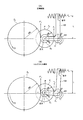
- FIG. 8 is a diagram for explaining the operating principle of the torque limiter.
- 101 is a fulcrum
- 102 is a torque arm
- Z 1 to Z 4 are gears
- R 1 to R 4 are pitch circle radii of each gear
- L is a distance from the fulcrum 101 to a point B of the torque arm 102.
- the torque arm 102 is coupled to the gear Z 1 at the fulcrum 101 to form a fulcrum of operation, and is coupled to the gears Z 2 and Z 3 at the point A of the torque arm 102 to the point B of the torque arm 102. And receive spring force.
- T 1 is the axial torque of the gear Z 1
- T ′ 2 is the counter-axis torque of the gear Z 4
- F 1 is the meshing tangential force over the gear Z 2
- F ′ 2 is the meshing tangential force over the gear Z 3
- P is the fulcrum 101 rotational force across the points a torque arm 102 as a fulcrum, when the spring force across the F 3 to the point B of the torque arm 102, the following equation is established.
- F 1 T 1 / R 1
- F ′ 2 T ′ 2 / R 4
- P F 1 + F ′ 2
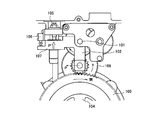
- FIG. 9 is a diagram for explaining the operating state of the torque limiter during the valve closing operation.
- This torque limiter is assumed to operate based on the operating principle described with reference to FIG.
- 101 is a fulcrum
- 102 is a torque arm
- 103 is a load side gear
- 104 is a load side drive shaft
- 105 is a torque adjusting screw
- 106 is a torque detection switch
- 107 is a torque balance disc spring (built in the torque arm 102). )
- And 108 are intermediate gears.
- the torque arm 102 is supported by the fulcrum 101 and is set to a predetermined torque value by the torque adjusting screw 105.
- the valve stopper hits the valve seat, and the load applied to the torque limiter increases rapidly.
- the intermediate gear 108 and the torque arm 102 meshing with the load-side gear 103 of the load-side drive shaft 104 are pushed in the direction P ′ in the figure, and the torque detection switch 106 is turned on. Operate.
- this torque detection switch 106 is activated, a master valve (not shown) is activated, and when the air motor (not shown) is stopped, the load side drive shaft 104 stops rotating and the closing operation of the torque limiter is completed.
- the torque limiter mounted on a conventional pneumatic valve actuator detects the torque when the valve is closed (closed side) and stops the air motor.
- the air microswitch detects the position.
- the air motor is stopped, if a malfunction such as the air micro switch does not work, the air motor will not stop, and the valve may be damaged or destroyed, which could lead to a serious accident. .
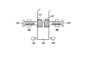
- FIG. 10 is a diagram schematically showing a structure when a torque limiter is provided for both opening and closing.
- reference numeral 102 denotes a torque arm
- 105 denotes a closing side torque adjustment screw
- 105 'de denotes an opening side torque adjusting screw
- 106 denotes a closing side torque detection switch
- 106' denotes an opening side torque detection switch.
- the present invention has been made in view of the above circumstances, and it is possible to detect torque for both opening and closing of a valve, and to easily adjust torque values different for each opening and closing.
- An object of the present invention is to provide a valve actuator provided.
- the first technical means includes a load side gear for rotationally driving a load, a drive side gear for driving the load side gear, and rotation of the drive side gear in the load
- a torque limiter built in a valve actuator for controlling an opening / closing operation of a valve connected to the load side gear via a drive shaft, the torque limiter being connected to the drive side
- a torque arm composed of a gear and a connecting portion connected to the intermediate gear and an arm portion protruding from the connecting portion; and when the valve is opened, the intermediate gear acts in the meshing tangential direction in proportion to the torque of the load.
- An opening-side spring means for applying a spring force that balances the force to be applied to the arm, and a force acting in the tangential direction of meshing of the intermediate gear in proportion to the torque of the load when the valve is closed.
- a closing-side spring means for applying a spring force to the arm, an opening-side torque detection switch that is operated by the arm when the torque of the load during opening of the valve exceeds a predetermined value, and the valve
- a closed-side torque detection switch that is operated by the arm when the torque of the load during a closing operation exceeds a predetermined value, and an opening-side spring means and a torque-limiter shaft that is passed through the closing-side spring means.
- the torque limiter shaft is characterized in that the spring force of the open side spring means and the spring force of the close side spring means can be adjusted respectively from one end of the torque limiter shaft. .
- the torque limiter shaft includes an open side adjustment shaft that passes through an open side moving piece urged by the open side spring means, and the open side adjustment shaft.
- a closing adjustment shaft that is provided coaxially and passes through a closing moving piece that is biased by the closing spring means, and the opening adjustment shaft and the closing adjustment shaft rotate independently of each other.
- the open side adjusting shaft is rotated to move the open side moving piece, the spring force of the open side spring means is adjusted, and the closed side adjusting shaft is rotated to rotate the closing side adjusting shaft.
- the side moving piece is moved to adjust the spring force of the closing side spring means.
- the third technical means is characterized in that, in the second technical means, a rotation preventing means is provided so that the opening side moving piece and the closing side moving piece do not rotate.
- the fourth technical means is a valve actuator incorporating the torque limiter in any one of the first to third technical means.
- the fifth technical means is characterized in that, in the fourth technical means, an opening is provided on a side surface, and one end of the torque limiter shaft is disposed in the vicinity of the opening.
- the present invention it is possible to detect torque for both opening and closing of the valve, and to adjust the torque value different for each opening and closing from one end of the torque limiter shaft. It is possible to efficiently perform torque adjustment work at the site after delivery.
- FIG. 1 It is an external view which shows an example of the pneumatic valve regulating valve provided with the valve actuator to which this invention is applied. It is a figure which shows the state which looked at the pneumatic valve control valve shown in FIG. 1 from the X direction. It is a figure which shows an example of the state which looked at the internal structure of the valve actuator which concerns on this invention from the upper surface. It is a figure which shows an example of the peripheral part of the torque limiter built in the valve actuator shown in FIG. It is a figure which shows the detailed structural example of the torque limiter which concerns on this invention. It is a figure which shows a mode that the opening part of the valve actuator shown in FIG. 4 was seen from the Y direction.
- FIG. 1 It is a block diagram which shows the structural example of the pneumatic valve control valve system provided with the valve actuator to which this invention is applied. It is a figure for demonstrating the principle of operation of a torque limiter. It is a figure for demonstrating the operation state of the torque limiter at the time of valve
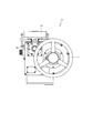
- FIG. 1 is an external view showing an example of a pneumatic valve control valve provided with a valve actuator to which the present invention is applied.
- FIG. 2 is a view showing a state in which the pneumatic valve control valve shown in FIG. 1 is viewed from the X direction.
- 1 is a valve actuator
- 2 is a valve bonnet
- 3 is a valve body
- 4 is a valve disk
- 5 is a load side drive shaft.
- the valve actuator 1 includes a handle 11, an air motor 12, and a master valve 13.
- a valve disk 4 for controlling the flow of fluid is provided inside a valve body 3 through which fluid such as oil flows.
- the valve disk 4 is connected to a handle 11 via a load side drive shaft 5.
- the valve motor 4 is moved up and down via the load side drive shaft 5 by operating the air motor 12 from a switch box (not shown) and rotating the load side drive shaft 5.
- the valve disk 4 is moved up and down via the load side drive shaft 5 by manually operating the handle 11 and rotating the load side drive shaft 5.
- the valve disk 4 reaches the lower part of the valve body 3, the valve disk 4 is fully closed.
- the valve disk 4 reaches the upper part of the valve bonnet 2, the valve disk 4 is fully opened.
- the valve actuator 1 incorporates a torque limiter (described later) corresponding to both opening and closing of the valve disc 4.
- This torque limiter has a torque detection switch for opening and closing, and when the torque detection switch on the closing side is activated, the master valve 13 is activated, the air motor 12 is stopped, the rotation of the load side drive shaft 5 is stopped, and the torque limiter is closed. Complete the action.
- the opening side torque detection switch when the opening side torque detection switch is operated, the master valve 13 is operated, the air motor 12 is stopped, the rotation of the load side drive shaft 5 is stopped, and the opening operation of the torque limiter is completed.
- FIG. 3 is a view showing an example of the internal structure of the valve actuator 1 according to the present invention as viewed from above.
- the valve actuator 1 includes a master valve 13, a closed side logic valve (LVC) 14, an open side logic valve (LVO) 15, a manual / automatic switching knob 16, a torque limiter 17, an instruction unit 18, a fully closed position detection switch 19, a fully open position.
- a position detection switch 20, a load side gear 21, a load side drive shaft 22 (corresponding to the load side drive shaft 5 described above), an intermediate gear 23, a drive side gear 24, a second gear 25, and a reduction plate 26 are provided.
- the master valve 13 controls the operation of the air motor 12 in accordance with an instruction from the LVC 14 or the LVO 15.
- the LVC 14 instructs the master valve 13 to control the air motor 12 to the closing side.
- the LVO 15 receives the opening operation signal from the open / close selector of the switch box (not shown)
- the LVO 15 instructs the master valve 13 to control the air motor 12 to the open side.
- the manual / automatic switching knob 16 is a switching means for switching between manual operation for opening and closing the valve by operating the handle 11 and automatic operation for opening and closing the valve by the air motor 12.
- the torque limiter 17 is a mechanism for detecting an appropriate torque required for opening and closing the valve and stopping the air motor 12. Details of the torque limiter 17 will be described with reference to FIGS.
- the instruction unit 18 acquires the rotation speed of the load side gear 21 and instructs the fully closed position detection switch 19 and the fully open position detection switch 20.
- the fully closed position detection switch 19 is a micro switch that detects when the number of rotations (position) of the load-side gear 21 acquired by the instruction unit 18 reaches the number of rotations corresponding to the fully closed position.
- the fully open position detection switch 20 is a micro switch that detects when the number of rotations (position) of the load side gear 21 acquired by the instruction unit 18 reaches the number of rotations corresponding to the fully open position. Note that the air motor 12 may be stopped by the fully open position detection switch 20 during a normal opening operation, and the air motor 12 may be stopped by an open-side torque limiter for backup when a problem occurs in this micro switch.
- the load side gear 21 is connected to a valve (not shown) via the load side drive shaft 22 and is a gear for rotationally driving the load.
- the drive side gear 24 is a gear for driving the load side gear 21.
- the intermediate gear 23 is a gear that transmits the rotation of the drive side gear 24 to the load side gear 21.
- the intermediate gear 23 of this example is composed of two gears: a gear that meshes with the load side gear 21 and a gear that meshes with the drive side gear 24.
- the second gear 25 is connected to the air motor 12 and transmits the driving force of the air motor 12 to the driving side gear 24. These second gear 25, drive side gear 24, and intermediate gear 23 are fixed by a reduction plate 26.
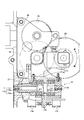
- FIG. 4 is a view showing an example of the peripheral portion of the torque limiter 17 built in the valve actuator 1 shown in FIG.
- the torque limiter 17 includes a torque arm 171 including a connecting portion 171b connected to the rotating shaft of the driving gear 24 and the rotating shaft of the intermediate gear 23, and an arm portion 171a protruding from the connecting portion 171b, and a load when the valve is opened.
- the open side spring means 172 for applying to the arm portion 171a a spring force P2 'that balances the force P2 acting in the meshing tangential direction of the intermediate gear 23 in proportion to the torque of the intermediate gear 23, and in proportion to the torque of the load when the valve is closed.
- Closed spring means 173 for applying to the arm portion 171a a spring force P1 'that balances the force P1 acting in the meshing tangential direction of the intermediate gear 23, and the arm when the torque of the load during the opening operation of the valve exceeds a predetermined value
- the opening side torque detection switch 175 operated by the portion 171a and the arm portion 171a when the load torque during the valve closing operation exceeds a predetermined value.
- the torque limiter shaft 176 is configured so that the spring force P2 ′ of the open side spring means 172 and the spring force P1 ′ of the close side spring means 173 can be adjusted from one end (Y direction in the figure) of the torque limiter shaft 176, respectively. Yes.
- the connecting portion 171b of the torque arm 171 is connected to the rotating shaft of the intermediate gear 23 and the rotating shaft of the driving gear 24, and an arm portion 171a is formed with the rotating shaft of the driving gear 24 as a fulcrum.
- the position of this fulcrum is not limited to this, and the connecting portion 171b may be an arbitrary point on an extension line extending from the rotation shaft of the drive side gear 24.
- the valve actuator 1 is provided with an opening 27 on a side surface, and one end of a torque limiter shaft 176 is disposed in the vicinity of the opening 27.
- a lid (not shown) can be attached to and detached from the opening 27, and when the torque is adjusted, the torque can be adjusted from one end of the torque limiter shaft 176 by simply removing the lid to open and close. Therefore, it is possible to efficiently perform the torque adjustment work in the pre-shipment inspection after the assembly is completed and the torque adjustment work in the site after the customer delivery.
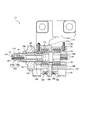
- FIG. 5 is a diagram showing a detailed configuration example of the torque limiter 17 according to the present invention.
- the torque limiter 17 includes the torque arm 171, the open side spring means 172, the close side spring means 173, the close side torque detection switch 174, the open side torque detection switch 175, and the torque limiter shaft 176 shown in FIG. Further, the shaft fixing nut 177, the knob nut 180, the adjustment screw mounting bracket 181, the closing side moving piece 182, the closing side transmission adjusting screw 183, the closing side spring receiver 184, the opening side spring receiver 185, the opening side transmission adjusting screw 186, the micro switch.
- a mounting plate 187, an opening-side spring retainer body 188, an opening-side moving piece 189, a piece rotation stopper 190, and a lock nut 191 are shown.
- the closed side torque detection switch 174 and the open side torque detection switch 175 are attached to the micro switch mounting plate 187, and the torque limiter shaft 176 is fixed to the casing of the valve actuator 1 by the adjusting screw mounting bracket 181.
- the micro switch mounting plate 187 is fixed to the adjustment screw mounting bracket 181 with screws.
- the open-side spring means 172 is housed in the open-side spring presser main body 188 and can be expanded and contracted between the open-side spring receiver 185 and the open-side moving piece 189. Further, the closing side spring means 173 can extend and contract between the closing side spring receiver 184 and the closing side moving piece 182.
- the open side spring means 172 and the close side spring means 173 are constituted by, for example, disc springs, and are integrally attached to the arm portion 171a of the torque arm 171.
- the torque limiter shaft 176 is provided coaxially with the open-side adjustment shaft 176a and is connected to the open-side adjustment shaft 176a through the open-side moving piece 189 biased by the open-side spring means 172, and is attached by the close-side spring means 173. And a closed side adjustment shaft 176b that passes through the closed side moving piece 182 that is energized.
- the open side adjustment shaft 176a and the close side adjustment shaft 176b can be rotated independently of each other. By rotating the open side adjustment shaft 176a, the open side moving piece 189 is moved, and the spring force of the open side spring means 172 is increased. By adjusting and rotating the closing side adjustment shaft 176b, the closing side moving piece 182 is moved and the spring force of the closing side spring means 173 is adjusted.
- the shaft fixing nut 177 and the knob nut 180 are loosened.
- the closed side adjusting shaft 176b is formed with screw parts n1 and n2, and this closed side adjusting shaft 176b is rotated in the axial direction by using a predetermined jig to close the closed side adjusting shaft 176b.
- the moving piece 182 is moved.
- the closed-side spring means 173 contracts to change the spring force and set the closed-side torque value.
- the torque value is increased
- the closed adjustment shaft 176b is rotated in the counterclockwise direction, the torque value is decreased.
- screw portions n3 and n4 are formed on the opening side adjusting shaft 176a.
- the opening side adjusting shaft 176a is a predetermined jig, and in this example, a minus driver is used as the groove portion 178.
- the opening-side moving piece 189 is moved by being fitted to the shaft and rotated in the axial direction.
- the open-side spring means 172 contracts to change the spring force and set the open-side torque value.
- the torque value is increased
- the open side adjustment shaft 176a is rotated in the counterclockwise direction, the torque value is decreased.
- a piece rotation stopper 190 is provided on the open side as a rotation preventing means so that the closing side moving piece 182 and the opening side moving piece 189 do not rotate during torque adjustment.
- the frame detent 190 is fixed by a lock nut 191.
- the opening side moving piece 189 is formed with a groove corresponding to the screw width of the piece rotation stopper 190, and the piece rotation stopper 190 is screwed into this groove and fixed with the lock nut 191.
- the side moving piece 189 can be prevented from rotating by the rotation of the mutual shaft.
- the arm portion 171a of the torque arm 171 moves in the right direction in the figure, so that the open-side transmission adjusting screw 186 is opened on the open-side torque detection switch (open-side micro switch) 175. Press. Further, when the torque value on the closing side is reached, the arm portion 171a of the torque arm 171 moves in the left direction in the figure, so that the closing side transmission adjusting screw 183 is closed on the closing side torque detection switch (closing side micro switch) 174. Press. This stops the air motor when the valve is opened or closed. At this time, since it is conceivable that the torque arm 171 slightly moves during the initial operation during opening and closing, a gap is provided between the transmission adjusting screw and the push button of the micro switch to prevent erroneous transmission.
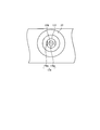
- FIG. 6 is a view showing a state in which the opening of the valve actuator 1 shown in FIG. 4 is viewed from the Y direction.
- one end of the torque limiter shaft 176 is disposed in the vicinity of the opening 27 of the valve actuator 1.
- a lid (not shown) is attachable to and detachable from the opening 27.
- the torque can be adjusted from one end of the torque limiter shaft 176 only by removing the lid. be able to. Thereby, the torque adjustment work in the pre-shipment inspection after the assembly is completed and the torque adjustment work in the site after the customer delivery can be efficiently performed.
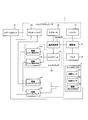
- FIG. 7 is a block diagram illustrating a configuration example of a pneumatic valve control valve system including the valve actuator 1 to which the present invention is applied.
- 6 is a set of three air points
- 7 is a switch box.
- the air three-point set 6 includes an air filter, a pressure reducing valve (regulator), and an oiler (lubricator), and is provided in a power air pipe.
- the switch box 7 includes a fully closed lamp 71, a fully opened lamp 72, and an open / close selector switch 73, and is provided directly on or away from the valve actuator 1.
- a closing operation signal is output to the closing logic valve 14.
- the closing side logic valve 14 that has received this closing operation signal instructs the master valve 13 to drive the air motor 12 to the closing side.
- the master valve 13 drives the air motor 12 to the closed side in accordance with this instruction.
- the reduction gear portion (the intermediate gear 23, the drive side gear 24, and the second gear 25) is rotated, the load side drive shaft 5 connected to these gears is rotated, and the valve 4 is rotated. Close operation.
- the torque arm 171 moves via the reduction gear portion (23, 24, 25), and the closed side torque detection switch 174 is operated.
- the close side torque detection switch 174 outputs a fully closed stop signal to the close side logic valve 14, and the close side logic valve 14 instructs the master valve 13 to stop the air motor 12.
- the master valve 13 stops the air motor 12 according to this instruction, and stops the rotation of the load side drive shaft 5.
- the fully closed position detection switch 19 (FIG. 3) outputs a fully closed signal to the switch box 7 to light the fully closed lamp 71.
- an open operation signal is output to the open logic valve 15.
- the open side logic valve 15 that has received this open operation signal instructs the master valve 13 to drive the air motor 12 to the open side.
- the master valve 13 drives the air motor 12 to the open side in accordance with this instruction.
- the reduction gear portion (the intermediate gear 23, the drive side gear 24, and the second gear 25) is rotated, the load side drive shaft 5 connected to these gears is rotated, and the valve 4 is rotated. Open operation.
- the torque arm 171 moves via the reduction gear portion (23, 24, 25), and the open side torque detection switch 175 is operated.
- the open side torque detection switch 175 outputs a fully open stop signal to the open side logic valve 15, and the open side logic valve 15 instructs the master valve 13 to stop the air motor 12.
- the master valve 13 stops the air motor 12 according to this instruction, and stops the rotation of the load side drive shaft 5.
- the fully open position detection switch 20 (FIG. 3) outputs a fully open signal to the switch box 7 to light the fully open lamp 72.
Abstract
Description
F1=T1/R1
F′2=T′2/R4
P=F1+F′2 T 1 is the axial torque of the gear Z 1 , T ′ 2 is the counter-axis torque of the gear Z 4 , F 1 is the meshing tangential force over the gear Z 2 , F ′ 2 is the meshing tangential force over the gear Z 3 , and P is the
F 1 = T 1 / R 1
F ′ 2 = T ′ 2 / R 4
P = F 1 + F ′ 2
P×(R1+R2)≦F3×L1
また、図8(B)に示すトルクリミット検出時には、下記式が成立する。
P×(R1+R2)>F3×L1 From the above formulas, the following formula is established during normal rotation shown in FIG.
P × (R 1 + R 2 ) ≦ F 3 × L 1
Further, the following formula is established when the torque limit shown in FIG.
P × (R 1 + R 2 )> F 3 × L 1
LVC14は、スイッチボックス(図示せず)の開閉セレクタから閉操作信号を受信すると、エアモータ12を閉側に制御するようにマスターバルブ13に指示する。
LVO15は、スイッチボックス(図示せず)の開閉セレクタから開操作信号を受信すると、エアモータ12を開側に制御するようにマスターバルブ13に指示する。 The
When receiving the closing operation signal from the open / close selector of the switch box (not shown), the
When the
トルクリミッタ17は、バルブの開閉時それぞれに必要な適正トルクを検出し、エアモータ12を停止させる機構である。このトルクリミッタ17の詳細は後述の図4~図6で説明する。 The manual /
The
全閉位置検出スイッチ19は、指示部18が取得した負荷側歯車21の回転回数(位置)が全閉位置に相当する回転回数になったときに、これを検出するマイクロスイッチである。
全開位置検出スイッチ20は、指示部18が取得した負荷側歯車21の回転回数(位置)が全開位置に相当する回転回数になったときに、これを検出するマイクロスイッチである。なお、通常の開動作時には全開位置検出スイッチ20でエアモータ12を停止させ、このマイクロスイッチに不具合が発生した場合のバックアップ用として、開側トルクリミッタによりエアモータ12を停止させるようにしてもよい。 The
The fully closed
The fully open
まず、軸固定ナット177、ノブナット180を緩める。閉側のトルク値を設定する場合、閉側調整軸176bにはネジ部n1,n2が形成されており、この閉側調整軸176bを所定の治具を用いて軸方向に回転させ、閉側移動コマ182を移動させる。これにより閉側バネ手段173が収縮し、バネ力を変化させ、閉側のトルク値を設定する。なお、本例では、閉側調整軸176bを時計方向に回転させると、トルク値が増加し、閉側調整軸176bを反時計方向に回転させると、トルク値が減少する。 Hereinafter, a method for adjusting the torque value in both directions of opening and closing by the
First, the
Claims (5)
- 負荷を回転駆動するための負荷側歯車と、該負荷側歯車を駆動するための駆動側歯車と、該駆動側歯車の回転を前記負荷側歯車に伝える中間歯車とを備え、前記負荷側歯車と駆動軸を介して連結されるバルブの開閉動作を制御するバルブアクチュエータに内蔵されるトルクリミッタであって、
該トルクリミッタは、前記駆動側歯車及び前記中間歯車に連結される連結部と該連結部から突出する腕部とからなるトルクアームと、前記バルブの開動作時に前記負荷のトルクに比例して前記中間歯車の噛み合い接線方向に作用する力と釣り合うバネ力を前記腕部に付与する開側バネ手段と、前記バルブの閉動作時に前記負荷のトルクに比例して前記中間歯車の噛み合い接線方向に作用する力と釣り合うバネ力を前記腕部に付与する閉側バネ手段と、前記バルブの開動作時における前記負荷のトルクが所定値を超えたときに前記腕部によって動作する開側トルク検出スイッチと、前記バルブの閉動作時における前記負荷のトルクが所定値を超えたときに前記腕部によって動作する閉側トルク検出スイッチと、前記開側バネ手段及び前記閉側バネ手段に軸通されたトルクリミッタ軸とを備え、
前記トルクリミッタ軸は、該トルクリミッタ軸の片端から、前記開側バネ手段のバネ力と前記閉側バネ手段のバネ力とをそれぞれ調整できるようにしたことを特徴とするトルクリミッタ。 A load side gear for rotationally driving a load; a drive side gear for driving the load side gear; and an intermediate gear for transmitting rotation of the drive side gear to the load side gear; A torque limiter built in a valve actuator for controlling the opening / closing operation of a valve connected via a drive shaft,
The torque limiter includes a torque arm including a connecting portion connected to the driving side gear and the intermediate gear, and an arm portion protruding from the connecting portion, and the torque proportional to the load torque when the valve is opened. An open-side spring means for applying a spring force to the arm portion that balances the force acting in the meshing tangential direction of the intermediate gear, and acting in the meshing tangential direction of the intermediate gear in proportion to the torque of the load when the valve is closed. A closing-side spring means for applying a spring force that balances the force to be applied to the arm, and an opening-side torque detection switch that is operated by the arm when the load torque exceeds a predetermined value when the valve is opened. A closing side torque detecting switch that is operated by the arm when the torque of the load during the closing operation of the valve exceeds a predetermined value, the opening side spring means, and the closing side bar. And a torque limiter shaft passed through the shaft to the means,
The torque limiter shaft is characterized in that the spring force of the open side spring means and the spring force of the close side spring means can be adjusted from one end of the torque limiter shaft, respectively. - 請求項1に記載のトルクリミッタにおいて、前記トルクリミッタ軸は、前記開側バネ手段により付勢される開側移動コマに軸通する開側調整軸と、該開側調整軸と同軸に設けられ且つ前記閉側バネ手段により付勢される閉側移動コマに軸通する閉側調整軸とから構成され、
前記開側調整軸と前記閉側調整軸は、互いに独立して回転可能とし、前記開側調整軸を回転させることにより、前記開側移動コマを移動させ、前記開側バネ手段のバネ力を調整し、また、前記閉側調整軸を回転させることにより、前記閉側移動コマを移動させ、前記閉側バネ手段のバネ力を調整することを特徴とするトルクリミッタ。 The torque limiter shaft according to claim 1, wherein the torque limiter shaft is provided coaxially with an open side adjustment shaft that passes through an open side moving piece urged by the open side spring means, and the open side adjustment shaft. And a closing side adjustment shaft that passes through the closing side moving piece biased by the closing side spring means.
The open side adjustment shaft and the close side adjustment shaft are rotatable independently of each other, and by rotating the open side adjustment shaft, the open side moving piece is moved and the spring force of the open side spring means is increased. A torque limiter that adjusts and rotates the closing side adjustment shaft to move the closing side moving piece to adjust the spring force of the closing side spring means. - 請求項2に記載のトルクリミッタにおいて、前記開側移動コマと前記閉側移動コマとが供回りしないように回り止め手段を備えたことを特徴とするトルクリミッタ。 3. The torque limiter according to claim 2, further comprising a detent means for preventing the opening-side moving piece and the closing-side moving piece from rotating.
- 請求項1~3のいずれか1項に記載のトルクリミッタを内蔵したバルブアクチュエータ。 A valve actuator incorporating the torque limiter according to any one of claims 1 to 3.
- 請求項4に記載のバルブアクチュエータにおいて、側面に開口部を設け、該開口部近傍に、前記トルクリミッタ軸の片端を配設したことを特徴とするバルブアクチュエータ。 5. The valve actuator according to claim 4, wherein an opening is provided on a side surface, and one end of the torque limiter shaft is disposed in the vicinity of the opening.
Priority Applications (4)
| Application Number | Priority Date | Filing Date | Title |
|---|---|---|---|
| US12/998,365 US20110193003A1 (en) | 2008-11-19 | 2009-04-20 | Torque limiter and valve actuator |
| EP09827396A EP2348238A4 (en) | 2008-11-19 | 2009-04-20 | Torque limiter and valve actuator |
| KR1020117010961A KR101213331B1 (en) | 2008-11-19 | 2009-04-20 | Torque limiter and valve actuator |
| CN2009801461873A CN102216660B (en) | 2008-11-19 | 2009-04-20 | Torque limiter and valve actuator |
Applications Claiming Priority (2)
| Application Number | Priority Date | Filing Date | Title |
|---|---|---|---|
| JP2008295569A JP4391576B1 (en) | 2008-11-19 | 2008-11-19 | Torque limiter and valve actuator |
| JP2008-295569 | 2008-11-19 |
Publications (1)
| Publication Number | Publication Date |
|---|---|
| WO2010058615A1 true WO2010058615A1 (en) | 2010-05-27 |
Family
ID=41549851
Family Applications (1)
| Application Number | Title | Priority Date | Filing Date |
|---|---|---|---|
| PCT/JP2009/057866 WO2010058615A1 (en) | 2008-11-19 | 2009-04-20 | Torque limiter and valve actuator |
Country Status (7)
| Country | Link |
|---|---|
| US (1) | US20110193003A1 (en) |
| EP (1) | EP2348238A4 (en) |
| JP (1) | JP4391576B1 (en) |
| KR (1) | KR101213331B1 (en) |
| CN (1) | CN102216660B (en) |
| TW (1) | TW201020432A (en) |
| WO (1) | WO2010058615A1 (en) |
Families Citing this family (6)
| Publication number | Priority date | Publication date | Assignee | Title |
|---|---|---|---|---|
| KR101379809B1 (en) * | 2013-05-20 | 2014-04-01 | 한국과학기술연구원 | Torque limiter with function of yielding torque change |
| EP3074672A4 (en) | 2013-11-28 | 2017-07-05 | Ham-Let (Israel-Canada) Ltd. | Valve device for controlling and adjusting fluid passage |
| KR101695233B1 (en) * | 2014-12-23 | 2017-01-11 | (주)에너토크 | Setting device |
| CN104653848B (en) * | 2015-02-13 | 2017-03-08 | 浙江澳翔自控科技有限公司 | A kind of switching mode torque adjusting mechanism turning round YE more |
| US10677363B2 (en) * | 2018-02-13 | 2020-06-09 | Dale S. Cheney | Water hammer prevention valve and method |
| US10962062B2 (en) | 2019-05-17 | 2021-03-30 | Caterpillar Inc. | Unidirectional torque-transfer coupling |
Citations (5)
| Publication number | Priority date | Publication date | Assignee | Title |
|---|---|---|---|---|
| JPS60159462A (en) * | 1984-01-30 | 1985-08-20 | Kohan Kogyo Kk | Valve shut-off device provided with torque limiter |
| JPH0427834A (en) * | 1990-05-22 | 1992-01-30 | Sanyo Oobaru Maintenance Kk | Torque meter and torque limiter |
| JPH0731090A (en) | 1993-07-09 | 1995-01-31 | Hitachi Ltd | Rotating electric machine |
| JP2004019938A (en) * | 2002-06-20 | 2004-01-22 | Kitz Corp | Actuator for valves |
| JP2008151293A (en) * | 2006-12-19 | 2008-07-03 | Yamatake Corp | Motor driven control valve and motor driven actuator |
Family Cites Families (8)
| Publication number | Priority date | Publication date | Assignee | Title |
|---|---|---|---|---|
| US3170339A (en) * | 1961-03-23 | 1965-02-23 | Link Belt Co | Valve operator |
| US4261224A (en) * | 1978-10-17 | 1981-04-14 | Anchor/Darling Industries, Inc. | Valve actuator |
| US4454504A (en) * | 1981-09-18 | 1984-06-12 | Westran Corporation | Torque overload indicator |
| FR2533333A1 (en) * | 1982-09-16 | 1984-03-23 | Bernard Ets L | Method of limiting the torque produced by a motor device and intended to drive a user device in movement and system for implementing this method |
| US4759224A (en) * | 1986-04-11 | 1988-07-26 | Movats Incorporated | Torque measuring system for motor operated valve operators |
| US5564677A (en) * | 1995-02-14 | 1996-10-15 | General Electric Company | Linear actuator with force switch for detecting axial load |
| US6003837A (en) * | 1996-02-20 | 1999-12-21 | Bray International, Inc. | Valve actuator |
| CA2490103C (en) * | 2002-06-20 | 2011-04-19 | Kitz Corporation | Actuator for valve |
-
2008
- 2008-11-19 JP JP2008295569A patent/JP4391576B1/en active Active
-
2009
- 2009-04-20 KR KR1020117010961A patent/KR101213331B1/en active IP Right Grant
- 2009-04-20 US US12/998,365 patent/US20110193003A1/en not_active Abandoned
- 2009-04-20 CN CN2009801461873A patent/CN102216660B/en active Active
- 2009-04-20 EP EP09827396A patent/EP2348238A4/en not_active Withdrawn
- 2009-04-20 WO PCT/JP2009/057866 patent/WO2010058615A1/en active Application Filing
- 2009-04-23 TW TW098113434A patent/TW201020432A/en unknown
Patent Citations (5)
| Publication number | Priority date | Publication date | Assignee | Title |
|---|---|---|---|---|
| JPS60159462A (en) * | 1984-01-30 | 1985-08-20 | Kohan Kogyo Kk | Valve shut-off device provided with torque limiter |
| JPH0427834A (en) * | 1990-05-22 | 1992-01-30 | Sanyo Oobaru Maintenance Kk | Torque meter and torque limiter |
| JPH0731090A (en) | 1993-07-09 | 1995-01-31 | Hitachi Ltd | Rotating electric machine |
| JP2004019938A (en) * | 2002-06-20 | 2004-01-22 | Kitz Corp | Actuator for valves |
| JP2008151293A (en) * | 2006-12-19 | 2008-07-03 | Yamatake Corp | Motor driven control valve and motor driven actuator |
Non-Patent Citations (1)
| Title |
|---|
| See also references of EP2348238A4 * |
Also Published As
| Publication number | Publication date |
|---|---|
| EP2348238A1 (en) | 2011-07-27 |
| US20110193003A1 (en) | 2011-08-11 |
| KR20110069177A (en) | 2011-06-22 |
| EP2348238A4 (en) | 2013-04-03 |
| CN102216660A (en) | 2011-10-12 |
| CN102216660B (en) | 2013-05-08 |
| TWI363843B (en) | 2012-05-11 |
| JP2010121702A (en) | 2010-06-03 |
| KR101213331B1 (en) | 2012-12-18 |
| JP4391576B1 (en) | 2009-12-24 |
| TW201020432A (en) | 2010-06-01 |
Similar Documents
| Publication | Publication Date | Title |
|---|---|---|
| JP4391576B1 (en) | Torque limiter and valve actuator | |
| EP1347249B1 (en) | Manual override and locking mechanism and actuator including same | |
| EP2356523B1 (en) | Hvac actuator with output torque compensation | |
| US8360393B2 (en) | Valve actuator having spring return power | |
| JP6520208B2 (en) | Electric valve actuator | |
| EP1671005B1 (en) | Improved arrangement in a swing door apparatus provided with a door closer | |
| NO341231B1 (en) | Valve actuator improvements | |
| CN101273179A (en) | Furniture hinge | |
| JP4695995B2 (en) | Sluice drive device for opening and closing the flow path | |
| JP4974226B2 (en) | Actuator | |
| JP4320315B2 (en) | Load body driving device for opening and closing flow path | |
| JP4986762B2 (en) | Electric actuator | |
| KR102228823B1 (en) | Actuator with elastic restoring function using reel spring | |
| JP4560365B2 (en) | Gate opening / closing drive device with hydraulic brake device | |
| JP4974225B2 (en) | Actuator | |
| JP4802117B2 (en) | Load body driving device for opening and closing flow path | |
| JP4974224B2 (en) | Actuator | |
| JP4957207B2 (en) | Forward / backward setting hydraulic switching device and automatic transmission | |
| JP5115809B2 (en) | Gas shut-off valve unit | |
| KR20050118142A (en) | A safety-valve with auto closing converter device | |
| JP2023131138A (en) | rotary actuator | |
| JP5264119B2 (en) | Electric actuator | |
| JP2004183747A (en) | Motor-operated valve | |
| JP2019207010A (en) | Electric valve actuator | |
| JP2005240600A (en) | Multiple throttle device |
Legal Events
| Date | Code | Title | Description |
|---|---|---|---|
| WWE | Wipo information: entry into national phase |
Ref document number: 200980146187.3 Country of ref document: CN |
|
| 121 | Ep: the epo has been informed by wipo that ep was designated in this application |
Ref document number: 09827396 Country of ref document: EP Kind code of ref document: A1 |
|
| DPE1 | Request for preliminary examination filed after expiration of 19th month from priority date (pct application filed from 20040101) | ||
| WWE | Wipo information: entry into national phase |
Ref document number: 12998365 Country of ref document: US |
|
| WWE | Wipo information: entry into national phase |
Ref document number: 2009827396 Country of ref document: EP |
|
| ENP | Entry into the national phase |
Ref document number: 20117010961 Country of ref document: KR Kind code of ref document: A |
|
| NENP | Non-entry into the national phase |
Ref country code: DE |