WO2010055818A1 - 超音波診断装置、超音波診断装置の信号処理実行方法 - Google Patents
超音波診断装置、超音波診断装置の信号処理実行方法 Download PDFInfo
- Publication number
- WO2010055818A1 WO2010055818A1 PCT/JP2009/069079 JP2009069079W WO2010055818A1 WO 2010055818 A1 WO2010055818 A1 WO 2010055818A1 JP 2009069079 W JP2009069079 W JP 2009069079W WO 2010055818 A1 WO2010055818 A1 WO 2010055818A1
- Authority
- WO
- WIPO (PCT)
- Prior art keywords
- signal processing
- processing
- name
- ultrasonic
- data
- Prior art date
- Legal status (The legal status is an assumption and is not a legal conclusion. Google has not performed a legal analysis and makes no representation as to the accuracy of the status listed.)
- Ceased
Links
Images


Classifications
-
- A—HUMAN NECESSITIES
- A61—MEDICAL OR VETERINARY SCIENCE; HYGIENE
- A61B—DIAGNOSIS; SURGERY; IDENTIFICATION
- A61B8/00—Diagnosis using ultrasonic, sonic or infrasonic waves
Definitions
- the present invention relates to an ultrasonic diagnostic apparatus, and more particularly to a technique for changing a signal processing configuration of a data conversion unit that converts a reflected echo signal from a subject into ultrasonic image data.
- the ultrasonic diagnostic apparatus transmits an ultrasonic wave to the inside of the subject using an ultrasonic probe, receives a reflected echo signal from the inside of the subject, and obtains, for example, a tomographic image (B mode image) of the imaging region of the subject. Generate and display for diagnosis.
- the ultrasonic diagnostic apparatus performs various signal processing on the reflected echo signal from the subject.
- ultrasonic scanning processing such as logarithmic compression processing and persistence processing
- TV scanning processing such as scanning conversion processing and gamma correction processing are used as data. It is executed and displayed by the conversion unit.
- the ultrasound diagnostic device generates various ultrasound images such as B-mode images, time-varying images of the imaging region (M-mode images), Doppler images obtained according to the blood flow velocity of the subject, etc. To display. Also, for example, B mode that displays a B mode image alone, B mode image and M mode image generated by parallel processing, and B / M mode that displays on the same screen, B mode image and Doppler image are generated by parallel processing. Many imaging modes such as B / D mode for displaying on the same screen.
- a plurality of data processing systems such as a memory and a digital scan converter (DSC) are provided in parallel. These are known to perform signal processing.
- DSC digital scan converter
- Patent Document 1 is signal processing executed in the data conversion unit. There is no consideration for flexible configuration changes.
- the data conversion unit has a signal processing configuration specific to the imaging mode (such as the signal processing to be executed and the execution order of the signal processing to be executed) set in advance, and performs various signal processing according to the signal processing configuration. It is desired to flexibly change this signal processing configuration.
- the signal processing configuration may be changed according to a client request or the like. In such a case, it takes time to rewrite and recompile the programming language base source code that describes the contents of each signal processing and the execution order, etc. It is not preferable from the viewpoint.
- an object of the present invention is to improve the flexibility of changing the signal processing configuration of the data converter.
- An ultrasonic diagnostic apparatus includes an ultrasonic probe that transmits an ultrasonic beam to a subject and receives a reflected echo signal from the subject, and a drive signal that transmits the ultrasonic beam to the ultrasonic probe.
- Forming a beam a data conversion unit for converting echo data obtained by digitizing the reflected echo signal into ultrasonic image data, and a display unit for displaying an ultrasonic image based on the converted ultrasonic image data And is configured.
- the echo data is subjected to a plurality of signal processing and converted into ultrasonic image data.
- an ultrasonic probe transmits an ultrasonic beam to a subject and receives a reflected echo signal from the subject;
- the processing configuration text described in the general language is rewritten without rewriting the source code in which the content of each signal processing itself is described in the programming language base. Only the signal processing configuration can be changed.
- the processing configuration text describes a plurality of signal processing names to be executed by the data converter, and input buffer names and output buffer names for each of the plurality of signal processing names.
- the execution order of the signal processing related to one signal processing name and the signal processing related to another signal processing name is described by matching the output buffer name in the signal processing name with the input buffer name in the other signal processing name. Can be configured.
- the input buffer name and the output buffer name may be rewritten to replace the connection information of the execution order between the signal processing. If a part of the signal processing is to be deleted, the signal processing name corresponding to the signal processing to be deleted may be deleted, and the input / output buffer name may be rewritten so as to match it. If signal processing is to be added, the signal processing name corresponding to the signal processing to be added is written, and the input / output buffer name is rewritten so as to match it.
- the processing configuration text that can be rewritten in a general language including the name of the signal processing used in the ultrasonic diagnostic apparatus and the input buffer name and output buffer name corresponding to each of the signal processing names,
- the processing configuration can be changed flexibly.
- the execution content of each signal processing itself is set in advance, and the processing configuration text describes which signal processing to be executed and in what order among a plurality of preset signal processing. It is.
- the processing configuration text includes a plurality of signal processing block names and a plurality of signals executed by the data conversion unit for each of the plurality of signal processing block names.
- a processing name and an input buffer name and an output buffer name corresponding to each of the plurality of signal processing names are described, and signal processing groups related to a plurality of signal processing names in each signal processing block name are assigned to a plurality of processors, respectively. It can be configured to be assigned and run in parallel.
- ultrasonic scanning processing such as logarithmic compression processing and persistence processing
- TV scanning processing such as scanning conversion processing and gamma correction processing
- the ultrasonic scanning process and the TV scanning process may have different processing rates, if they are executed by the same processor, a processing loss occurs, which is not preferable from the viewpoint of processing efficiency. Therefore, for example, by assigning signal processing with different processing rates to a plurality of processors of the data conversion unit and performing parallel processing, it is possible to improve processing efficiency.
- the parallel signal processing can be described easily. Can do.
- the processing configuration text includes a synchronization name for a pair of signal processing names executed in synchronization between a signal processing group related to one signal processing block name and a signal processing group related to another signal processing block name. Can be described, and signal processing related to the signal processing name in which the synchronization name is described can be executed in synchronization with each other.
- the ultrasonic diagnostic apparatus has various imaging modes.For example, when a B mode image and a Doppler image are generated in parallel in the B / D mode, and these are combined and displayed, both are combined in the combining process. Need to be synchronized.
- the synchronization between parallel processes can be described easily by making it possible to describe the synchronization names for a pair of signal processing names executed synchronously as in the present invention.
- processing configuration text enables description of a table name in which processing coefficients used for signal processing are stored for a signal processing name, and executes signal processing related to the signal processing name in which the table name is described.
- the processing coefficient relating to the table name can be referred to.
- the flexibility of changing the signal processing configuration of the data converter can be improved.
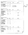
- FIG. 10 is a diagram illustrating a description example of the processing configuration text according to the first embodiment.
- Diagram showing the processing flow from generation of B-mode image using two processors to output to video memory The figure which shows the example of a description of the process structure text of Example 2.
- Diagram showing the processing flow from generation of B-mode image and Doppler image to output to video memory using four processors The figure which shows the example of a description of the process structure text of Example 3.
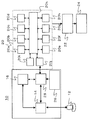
- FIG. 1 is a block diagram showing the configuration of an ultrasonic diagnostic apparatus to which the present invention is applied.
- the ultrasonic diagnostic apparatus 10 of the present invention transmits an ultrasonic beam to a subject and receives an echo signal from the subject, and an ultrasonic probe 12 (PROBE).
- Transmission / reception switching unit 14 PRB that switches transmission / reception of the acoustic probe 12
- a beam forming unit 16 DLF
- DPF beam forming unit 16
- a subject Data conversion unit 20 that performs multiple signal processing on echo data digitized from echo signals reflected from the image and converts them into ultrasound image data, ultrasound images based on the ultrasound image data converted by the data conversion unit 20, etc.
- a display unit 24 for displaying an ultrasonic image stored in the video memory 22, and the like.
- a setting unit 26 for setting the imaging mode data of the ultrasound image data to echo data
- a data set is generated by adding the imaging mode data and the echo data
- the data set is sent to the data conversion unit 20 as data.
- control the data conversion unit 20 to analyze the imaging mode data in the data set, and to convert the echo data in the data set into ultrasound image data by the analyzed imaging mode data ( CONT).
- transducers are arranged for 1 to m channels in the long axis direction of the ultrasonic probe.
- the minor axis direction can be changed by changing the delay time given to each transducer (1 to k channels) in the minor axis direction.
- transmission weighting is performed by changing the amplitude of the ultrasonic transmission signal applied to each transducer in the short axis direction, and by changing the amplification or attenuation of the ultrasonic reception signal from each transducer in the short axis direction Receive weighting is applied.
- the aperture control can be performed by turning on and off each vibrator in the short axis direction.
- a transducer is formed by a piezoelectric element.
- cMUT Capacitive Micromachined Ultrasonic Transducer: IEEE Trans. Ultrason. Ferroelect. Freq. Contr. Vol45 pp. 678-690 May 1998) It is also possible to apply a vibrator in which a vibrator is formed of a semiconductor called “semiconductor”.
- the transmission / reception switching unit 14 serves as an interface for supplying a transmission signal to the ultrasonic probe 12 and processing a received reflected echo signal.
- the transmission / reception switching unit 14 has a function of a receiving circuit that receives reflected echo signals from within the subject with respect to the ultrasonic beam transmitted to the subject and collects biological information.
- the beam forming unit 16 is a transmission circuit that controls the ultrasonic probe 12 to emit an ultrasonic beam, and determines the transmission timing of ultrasonic pulses that drive the plurality of transducers of the ultrasonic probe 12.
- the ultrasonic beam is formed to be controlled to a focal point set in the subject. Further, the ultrasonic beam is electronically scanned in the arrangement direction of the transducers of the ultrasonic probe.
- the data conversion unit 20 receives the echo data that has been received by the transmission / reception switching unit 14 and then subjected to reception processing such as amplification, A / D conversion, and processing to add the phases of a plurality of transducers in a uniform manner.
- reception processing such as amplification, A / D conversion, and processing to add the phases of a plurality of transducers in a uniform manner.
- Various signal processing to be described later is performed and converted into ultrasonic tomographic image data, and an ultrasonic image is formed based on sequentially inputted echo data.
- Ultrasound images include A-mode images, B-mode images, color flow mapping (C) mode images, Doppler (D) mode images, elastic (elast) (E) mode images, M-mode images, mainly the subject's body. There are three-dimensional ultrasonic images obtained by reconstructing B-mode images arranged continuously along the table.
- the video memory 22 synthesizes and stores the ultrasonic image formed by the data conversion unit 20, characters and graphic information such as patient information and body mark information, and graphic information of the setting unit 26.
- the control unit 28 also has a display control unit function for selecting and controlling what display format is used for display.
- the display unit 24 displays an ultrasonic image stored in the video memory 22, and is composed of, for example, a CRT monitor or a liquid crystal monitor.
- the display unit 24 only needs to display an ultrasonic image and display an image that can be diagnosed by the operator, and any one of analog output and digital output can be applied to the present invention.
- the setting unit 26 is used by an operator to input various parameters such as a desired imaging mode, patient information, and imaging position using a keyboard or trackball on the console.
- the control unit 28 is a control computer system that controls the transmission / reception switching unit 14, the beam forming unit 16, and the data conversion unit 20 to function based on various parameters input by the setting unit 26.
- the data conversion unit 20 records a plurality of processors 20a to 20h, a processor control unit 20i that collectively controls the processors 20a to 20h, and echo data sent via the transmission / reception switching unit 14.
- the internal memory 20j (MEMORY), the processors 20a to 20h, the processor control unit 20i, and the internal memory 20j are provided with an internal data transfer bus 20k capable of communicating data with each other.
- the internal memory 20j receives and stores data transferred from the control unit 28 (CONT).
- the processor control unit 20i controls the processors 20a to 20h connected via the internal data transfer bus 20k.
- a specific example of the control is to analyze data and parameters stored in the internal memory 20j, assign a processing program to the processors 20a to 20h, and obtain an ultrasound image from the data stored in the internal memory 20j.
- the data conversion unit 20 may be a multiprocessor in which an architecture having a plurality of processor cores in a single package such as CELL is standardized.
- CELL is an abbreviation for Cell Broadband Engine (registered trademark) and is a microprocessor developed by Sony Computer Entertainment Inc.
- the processors 20a to 20h are configured as SPE (Synergistic Processor Processor Element)
- the processor control unit 20i is configured as PPE (PowerPC Processor Processor Element)
- the internal data transfer bus 20k is configured as EIB (Element Interconnector Bus).
- the ultrasonic diagnostic apparatus there is a demand for a reduction in the circuit scale of the data processing unit that contributes to the miniaturization of the apparatus, while at the same time the speed of the data arithmetic processing of the data processing unit that contributes to the enhancement of the function of the apparatus.
- the number of processors is eight as an example in FIG. 1, but any number of natural numbers may be used because it can be arbitrarily set according to the processing capability of the processor.
- a signal processing configuration specific to the imaging mode (such as the signal processing to be executed and the execution order of the signal processing to be executed) is preset in the data conversion unit 20.
- processing is performed according to the signal processing configuration.
- the signal processing configuration may be changed according to a client request or the like.
- the ultrasonic diagnostic apparatus 10 of the present embodiment has a plurality of signal processing executed by the data conversion unit 20 and a processing configuration text in which the execution order of the plurality of signal processings can be rewritten in a general language.
- the unit 20 is configured to perform a plurality of signal processing on the echo data based on the description of the processing configuration text 30 and convert it to ultrasonic image data.
- description of the processing configuration text 30 for each imaging mode will be described.
- Example 1 is a description example of a processing configuration text when one processor of the data conversion unit 20 executes signal processing.
- FIG. 2 is a diagram showing a processing flow until a B-mode image is generated and output to the video memory 22 using one processor.
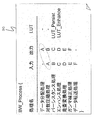
- FIG. 3 is a diagram illustrating an example in which the signal processing of the present embodiment is described in the processing configuration text.
- the processes required until the B-mode image is generated and displayed roughly include a data distribution process, a logarithmic compression process, a persistence process, an enhancement process, a scan conversion process, a gamma correction process, and a data transfer process.
- These signal processes are assigned to any one of the processors 20a to 20h and executed by the processor control unit 20i. In this embodiment, it is assumed that the processor 20a is assigned.
- the processing target echo data input via the control unit 28 is in the B mode, and the processing target echo data is taken into the processor 20a based on the determination.
- the determination of the echo data can be performed by the data conversion unit 20 analyzing the data indicating the beam type set accompanying the echo data.
- Logarithmic compression processing compresses the dynamic range of an ultrasonic reception signal, for example, which is 2 to the 20th power, to a relatively small dynamic range on a circuit, substantially a monitor dynamic range.
- the persistence process the data displayed at the same position on the monitor are added and averaged with respect to the pixels after the logarithmic compression process.
- edge enhancement is performed so that the boundary between the pixels becomes clear with respect to the pixels after the persistence processing.
- the pixel after the enhancement process is coordinate-converted from the scan of the ultrasonic beam to the scan of the display monitor.
- the display gradation is corrected with respect to the pixel after the scan conversion process by a gamma curve that determines the definition area and value range of the pixel.
- the image after the gamma correction process (B mode image) is sent to the video memory 22.
- BW_Process is described as a signal processing block name in the processing configuration text 30, and the description in the signal processing block is enclosed in ⁇ brackets.
- the signal processing names are described in the order of processing in the signal processing name column.
- input / output buffer names are described for each signal processing name as a connection for connecting each signal processing.
- the buffer B processed by logarithmic compression processing is the input for persistence processing, and the processing is connected as pipeline processing. It will be.
- the output buffer name (B) in one signal processing name logarithmic compression processing
- the input buffer name (B) in another signal processing name end stance processing
- each signal processing is sequentially executed on the echo data based on the description of the processing configuration text 30.
- the content of each signal processing is set in advance, and the signal processing described in the processing configuration text 30 is executed in the order based on the description.
- LUT Look Up Table
- LUT_Persist is described for the persistence processing
- LUT_Enhance is described for the enhancement processing.
- a coefficient LUT prepared in advance can be used, LUT_Persist is referenced when executing the persistence processing in which the table name is described, and LUT_Enhance is referenced when executing the enhancement processing.
- the processing configuration text 30 describes a plurality of signal processes executed by the data converter 20 and an execution order of the plurality of signal processes so that they can be rewritten in a general language.
- the general language means a signal processing block name for capturing a plurality of signal processing as a unit, a signal processing name used in the ultrasonic diagnostic apparatus, and an execution order of each signal processing, as in this embodiment.
- the input / output buffer name used as the connection information of the data and the table name storing the processing coefficients used for signal processing are included.
- the signal processing block name, the input field for describing each, ⁇ brackets, etc. are described in advance as a format, and the connection is made by the signal processing name and the input / output buffer name indicating the execution order of the signal processing.
- a signal processing group can be processed by a processor of the data converter 20 only by describing information. Therefore, if the execution order of the signal processing is to be changed, the connection information based on the input / output buffer name of the processing configuration text 30 may be rewritten.
- the signal processing configuration text 30 may be deleted from the processing configuration text 30, and the connection information based on the input / output buffer name may be rewritten so as to match this.
- the signal processing configuration can be easily changed by rewriting the description of the processing configuration text 30 without changing the source code itself described in the programming language of the data conversion unit 20, for example.
- the signal processing configuration can be flexibly changed. For example, it is possible to easily verify how the appearance of an ultrasonic image changes when the order of signal processing is changed.
- the signal processing configuration is described so that it can be listed as text, it is easy to grasp the overall structure of the signal processing configuration. As a result, the development efficiency of the ultrasonic diagnostic apparatus can be improved.
- the signal processing configuration can be flexibly changed according to the request of the client, so that the maintenance efficiency can be improved.
- Example 2 is a description example of a processing configuration text when two processors of the data conversion unit 20 execute signal processing in parallel.
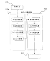
- FIG. 4 is a diagram showing a processing flow until a B-mode image is generated and output to the video memory 22 using two processors.
- FIG. 5 is a diagram showing an example in which the signal processing of the present embodiment is described in the processing configuration text.
- the processes required until the generation and display of the B-mode image are the same as in the first embodiment: data distribution process, logarithmic compression process, persistence process, enhancement process, scan conversion process, gamma correction process, data Approximate from the transfer process.
- data distribution process logarithmic compression process
- persistence process persistence process
- enhancement process scan conversion process
- gamma correction process data Approximate from the transfer process.
- a B-mode image is an image data scanning process, logarithmic compression process, persistence process, enhancement process, ultrasonic scanning process, scan conversion process, gamma correction process, and data transfer process. It can be divided into scanning processes.
- the ultrasonic scanning process is assigned to any one of the processors 20a to 20h by the processor control unit 20i, and the TV scanning process is assigned to any one other than the processors 20a to 20h not assigned to the ultrasonic scanning process.
- the ultrasonic scanning process is assigned to the processor 20a (BM1) and the TV scanning process is assigned to the processor 20b (BM2).
- the ultrasonic scanning process and the TV scanning process have different processing rates, it is preferable to execute them by assigning them to different processors from the viewpoint of processing efficiency.
- these two scanning processes can be processed exclusively, it is possible to increase the speed by parallel processing in the pipeline method.
- BW_US_Process and BW_Video_Process are described as signal processing block names, and descriptions in these signal processing blocks are enclosed in ⁇ brackets.
- the signal processing names are described in the order of processing in the column of the signal processing name. That is, the BW_US_Process block describes data distribution processing, logarithmic compression processing, persistence processing, and enhancement processing, and the BW_Video_Process block describes scan conversion processing, gamma correction processing, and data transfer processing.
- input / output buffer names are described for each signal processing name as a connection for connecting each signal processing.
- signal processing can be connected across signal processing blocks so that the output buffer for enhancement processing is D and the input for scan conversion processing is D buffer.
- the buffer D processed by the enhancement process becomes an input of the scan conversion process, and the process is connected as a pipeline process.
- the signal processing block name, the input field for describing each, ⁇ brackets, etc. are described in advance as a format, and the connection is made by the signal processing name and the input / output buffer name indicating the execution order of the signal processing. Only by describing information, a plurality of signal processing groups can be processed in parallel by a plurality of processors of the data conversion unit 20.
- signal processing groups (ultrasonic scanning processing group and TV scanning processing group) related to a plurality of signal processing names in each signal processing block name are assigned to a plurality of processors (processors 20a and 20b) and executed in parallel. Is done. In this way, when it is desired to execute a plurality of signal processing groups in parallel, it is divided by the signal processing block name in the processing configuration text 30 and only a plurality of the signal processing blocks are described. It is possible to easily change the signal processing configuration without changing the described source code itself.
- the data conversion unit 20 includes a plurality of processors, and in order to efficiently drive the plurality of processors in parallel, the signal processing configuration in consideration of the processing rate of each signal processing It is necessary to evaluate the performance of the apparatus while changing the above.
- parallel signal processing can be easily described in the processing configuration text 30, and the signal processing configuration can be easily changed. Development efficiency of the ultrasonic diagnostic apparatus can be improved.
- Example 3 is a description example of a processing configuration text when the four processors of the data conversion unit 20 execute signal processing in parallel and perform synchronization between the parallel processings.
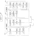
- FIG. 6 is a diagram showing a processing flow until a B-mode image and a Doppler image are generated and output to the video memory 22 using four processors.
- FIG. 7 is a diagram illustrating an example in which the signal processing of the present embodiment is described in the processing configuration text.
- the present embodiment generates and displays a B-mode image and a Doppler image.
- the description of the same part as in the second embodiment is omitted, and only the different part will be described.
- the B-mode image TV scanning process a composition process is inserted between the gamma correction process and the data transfer process.
- the combining process combines the data after the Doppler image TV scanning process described later and the B-mode image.
- the image after the combination process (the combined image of the B-mode image and the Doppler image) is sent to the video memory 22.
- Processing required to generate and display a Doppler image includes data distribution processing, sample gate (SG) setting processing, resample processing, fast Fourier transform (FFT) processing, addition averaging processing, logarithmic compression processing, storage processing, and scan conversion processing. Approximate from gamma correction processing.
- Each of these processes includes data distribution processing, SG setting processing, resampling processing, Fast Fourier Transform (FFT) processing, addition averaging processing, ultrasonic scanning processing consisting of logarithmic compression processing, storage processing, scanning conversion processing, gamma correction It can be divided into TV scanning processing consisting of processing.
- FFT Fast Fourier Transform
- the ultrasonic scanning process is assigned to one of the processors 20a to 20h by the processor control unit 20i, and the TV scanning process is assigned to any of the processors 20a to 20h not assigned to the ultrasonic scanning process.
- the B-mode image ultrasonic scanning process is assigned to the processor 20a (BM1) and the TV scanning process is assigned to the processor 20b (BM2).
- the Doppler image ultrasonic scanning process is assigned to the processor 20c (DM1) and the TV scanning process is assigned to the processor 20d (DM2).
- the process target echo data is taken into the processor 20c based on the determination.
- the determination of the echo data can be performed by the data conversion unit 20 analyzing the data indicating the beam type set accompanying the echo data.
- the SG setting process sets SG at a desired blood flow velocity diagnosis site on the ultrasonic B-mode image of the subject.
- the resampling process is obtained by interpolating sample points to be calculated by a subsequent Fourier transform.
- FFT processing frequency analysis is performed on sample points interpolated by resampling, and relatively low-frequency clutter components from reflectors with slow motion speed, such as the myocardium, are removed, and relatively high-frequency blood flow components are extracted. To do.
- averaging process a correlation value for each sample point is obtained for the blood flow component extracted by the FFT process.
- the dynamic range of the result of the averaging process is substantially compressed to the dynamic range of the monitor.
- the storage process stores the result of logarithmic compression processing in the internal memory 20j.
- the pixels stored in the internal memory 20j are coordinate-converted from the scan of the ultrasonic beam to the scan of the display monitor.
- the gamma correction process the display gradation is corrected with respect to the pixel after the scan conversion process by a gamma curve that determines the definition area and the value area of the pixel, and is output to the B-mode image synthesis process.
- BM1 which is ultrasonic scanning processing of B mode image processing and DM1 which is ultrasonic scanning processing of Doppler image processing need to operate in different processing units.
- BM2 that is TV scanning processing and DM2 that is TV scanning processing of Doppler image processing need to be synchronized because they need to be output to the video memory 22 in the same processing unit.
- the BW_US_Process block describes data distribution processing, logarithmic compression processing, persistence processing, and enhancement processing
- the BW_Video_Process block describes scan conversion processing, gamma correction processing, and data transfer processing.
- the DOP_US_Process block describes data distribution processing, SG setting processing, resampling processing, FFT processing, addition averaging processing, and logarithmic compression processing
- the DOP_Video_Process block describes scanning conversion processing and gamma correction processing. ing.
- the input / output buffer name is described for each signal processing name as a connection for connecting each signal processing.
- the B-mode image ultrasound scanning process (BM1) and the Doppler image ultrasound scanning process (DM1) do not need to be synchronized with each other. are described in the order of processing as connection information.
- the B-mode image TV scanning process (BM2) and the Doppler image TV scanning process (DM2) combine both images in the combining process, so the combining process in the B-mode image TV scanning process is 2 Has two inputs (connection information).
- the synthesis process is performed on the B-mode TV scanning process side, it is necessary to wait for the gamma correction process on the TV scanning process side of the Doppler image to end before the synthesis process. For this reason, synchronization processing is required on the TV scan processing side of the B-mode image before synthesis processing and on the TV scan processing side of the Doppler image after gamma correction.
- synchronization processing a signal processing name called synchronization processing is described before the synthesis processing in the TV scanning processing block of the B-mode image, and the sync column, which is a column describing the synchronization name corresponding to this synchronization processing, is described.
- Sync1 is described as the synchronization name.
- the signal processing name of synchronization processing is described after the gamma correction processing in the TV scanning processing block of the Doppler image, and sync1 is set as the synchronization name in the sync column that describes the synchronization name corresponding to this synchronization processing. is described.
- a synchronization process is required at the end of the TV scan process for the B-mode image and the TV scan process for the Doppler image. Therefore, in the processing configuration text 30, a signal processing name called synchronization processing is described after the data transfer processing in the TV scanning processing block of the B mode image, and the sync column which is a column describing the synchronization name corresponding to this synchronization processing , Sync2 is described as the synchronization name. In addition, a signal processing name called synchronization processing is described after the synchronization processing corresponding to sync1 in the TV scanning processing block of the Doppler image, and the synchronization name is displayed in the sync column that describes the synchronization name corresponding to this synchronization processing. As sync2 is described.
- the synchronization names can be described with respect to the signal processing name (synchronization processing), and the signal processing related to the signal processing name in which the synchronization name is described is executed in synchronization with each other.
- the signal processing block name, the input field for describing each, ⁇ brackets, etc. are described in advance as a format, and the connection is made by the signal processing name and the input / output buffer name indicating the execution order of the signal processing. It is possible to easily describe synchronization between parallel processes only by describing information and a synchronization name.
- the signal processing configuration can be easily changed without changing the source code itself described in the programming language of the data conversion unit 20, for example.
Landscapes
- Life Sciences & Earth Sciences (AREA)
- Health & Medical Sciences (AREA)
- Biomedical Technology (AREA)
- Biophysics (AREA)
- Nuclear Medicine, Radiotherapy & Molecular Imaging (AREA)
- Pathology (AREA)
- Radiology & Medical Imaging (AREA)
- Engineering & Computer Science (AREA)
- Physics & Mathematics (AREA)
- Heart & Thoracic Surgery (AREA)
- Medical Informatics (AREA)
- Molecular Biology (AREA)
- Surgery (AREA)
- Animal Behavior & Ethology (AREA)
- General Health & Medical Sciences (AREA)
- Public Health (AREA)
- Veterinary Medicine (AREA)
- Ultra Sonic Daignosis Equipment (AREA)
Abstract
Description
と呼ばれる半導体により振動子が形成されるものを適用することもできる。
本実施例ではプロセッサ20aに割り当てられているとする。
図3に示すように、処理構成テキスト30には、信号処理ブロック名としてBW_Processが記述され、この信号処理ブロック内の記述が{}かっこでくくられている。信号処理ブロック内は、信号処理名の欄に上述の各信号処理の名前が処理順に記述されている。
例えば信号処理の順序を入れ換えた場合の超音波画像の見え方はどのように変化するかなどを容易に検証することができる。また、信号処理構成がテキストとして一覧できるように記述されているため、信号処理構成の全体構造の把握が容易になる。その結果、超音波診断装置の開発効率を向上させることができる。また、例えば超音波診断装置のメンテナンス段階で、クライアントの要求等に応じて信号処理構成の変更を柔軟に行なうことができるので、メンテナンス効率を向上させることができる。
図5に示すように、処理構成テキスト30には、信号処理ブロック名としてBW_US_ProcessとBW_Video_Processと記述され、これらの信号処理ブロック内の記述がそれぞれ{}かっこでくくられている。信号処理ブロック内は、それぞれ信号処理名の欄に上述の各信号処理の名前が処理順に記述されている。つまり、BW_US_Processブロックにはデータ分配処理、対数圧縮処理、パーシスタンス処理、及びエンハンス処理が記述されており、BW_Video_Processブロックには走査変換処理、ガンマ補正処理、及びデータ転送処理が記述されている。
また、ドプラ像の超音波走査処理がプロセッサ20c(DM1)に割り当てられ、TV走査処理がプロセッサ20d(DM2)に割り当てられているとする。
Claims (6)
- 被検体に超音波ビームを送信するとともに前記被検体からの反射エコー信号を受信する超音波探触子と、該超音波探触子に前記超音波ビームを送信させる駆動信号を供給するビーム形成部と、前記反射エコー信号をデジタル化して得られたエコーデータを超音波画像データへ変換するデータ変換部と、前記変換された超音波画像データに基づく超音波画像を表示する表示部とを備えた超音波診断装置であって、
前記データ変換部で実行する複数の信号処理及び該複数の信号処理の実行順序を一般言語で書き換え可能な処理構成テキストを有し、前記データ変換部は前記処理構成テキストの記述に基づいて前記エコーデータに複数の信号処理を実行して前記超音波画像データへ変換する制御部を備えたことを特徴とする超音波診断装置。 - 前記処理構成テキストは、前記データ変換部で実行する複数の信号処理名と、該複数の信号処理名のそれぞれに対する入力バッファ名及び出力バッファ名とを記述するようになっており、一の信号処理名における出力バッファ名と他の信号処理名における入力バッファ名とを一致させることにより前記一の信号処理名に係る信号処理と他の信号処理名に係る信号処理の実行順序を記述する請求項1記載の超音波診断装置。
- 前記データ変換部は複数のプロセッサを有して構成され、
前記処理構成テキストは、複数の信号処理ブロック名と、該複数の信号処理ブロック名のそれぞれに対する前記データ変換部で実行する複数の信号処理名と、該複数の信号処理名のそれぞれに対する入力バッファ名及び出力バッファ名とを記述するようになっており、前記各信号処理ブロック名における複数の信号処理名に係る信号処理群がそれぞれ前記複数のプロセッサに割り当てられて並列に実行される請求項2記載の超音波診断装置。 - 前記処理構成テキストは、一の信号処理ブロック名に係る前記信号処理群と他の信号処理ブロック名に係る前記信号処理群の相互間で同期して実行される一対の信号処理名に対して同期名を記述可能になっており、前記同期名が記述された信号処理名に係る信号処理は互いに同期して実行される請求項3記載の超音波診断装置。
- 前記処理構成テキストは、前記信号処理名に対して信号処理に用いられる処理係数が格納されたテーブル名を記述可能になっており、前記テーブル名が記述された信号処理名に係る信号処理を実行する際に該テーブル名に係る処理係数が参照される請求項2記載の超音波診断装置。
- 超音波探触子が被検体に超音波ビームを送信するとともに前記被検体からの反射エコー信号を受信するステップと、ビーム形成部が該超音波探触子に前記超音波ビームを送信させる駆動信号を供給するステップと、データ変換部が前記反射エコー信号をデジタル化して得られたエコーデータを超音波画像データへ変換するステップと、表示部が前記変換された超音波画像データに基づく超音波画像を表示するステップと、制御部が前記データ変換部で実行する複数の信号処理及び該複数の信号処理の実行順序を一般言語で書き換え可能な処理構成テキストを有し、前記データ変換部は前記処理構成テキストの記述に基づいて前記エコーデータに複数の信号処理を実行して前記超音波画像データへ変換するステップを含むことを特徴とする超音波診断装置の信号処理実行方法。
Priority Applications (2)
| Application Number | Priority Date | Filing Date | Title |
|---|---|---|---|
| US13/129,262 US20110218440A1 (en) | 2008-11-14 | 2009-11-10 | Ultrasonic diagnostic apparatus and signal processing method in ultrasonic diagnostic apparatus |
| JP2010537768A JP5496910B2 (ja) | 2008-11-14 | 2009-11-10 | 超音波診断装置、超音波診断装置の信号処理実行方法 |
Applications Claiming Priority (2)
| Application Number | Priority Date | Filing Date | Title |
|---|---|---|---|
| JP2008292372 | 2008-11-14 | ||
| JP2008-292372 | 2008-11-14 |
Publications (1)
| Publication Number | Publication Date |
|---|---|
| WO2010055818A1 true WO2010055818A1 (ja) | 2010-05-20 |
Family
ID=42169952
Family Applications (1)
| Application Number | Title | Priority Date | Filing Date |
|---|---|---|---|
| PCT/JP2009/069079 Ceased WO2010055818A1 (ja) | 2008-11-14 | 2009-11-10 | 超音波診断装置、超音波診断装置の信号処理実行方法 |
Country Status (3)
| Country | Link |
|---|---|
| US (1) | US20110218440A1 (ja) |
| JP (1) | JP5496910B2 (ja) |
| WO (1) | WO2010055818A1 (ja) |
Families Citing this family (4)
| Publication number | Priority date | Publication date | Assignee | Title |
|---|---|---|---|---|
| WO2010143587A1 (ja) * | 2009-06-10 | 2010-12-16 | 株式会社 日立メディコ | 超音波診断装置、超音波画像処理装置、超音波画像処理プログラム、及び超音波画像生成方法 |
| US20140257102A1 (en) * | 2013-03-07 | 2014-09-11 | Volcano Corporation | Devices, Systems, and Methods for Dual Image Intravascular Ultrasound |
| CN111544038B (zh) * | 2020-05-12 | 2024-02-02 | 上海深至信息科技有限公司 | 一种云平台超声成像系统 |
| CN113325398B (zh) * | 2021-05-13 | 2024-08-23 | 英博超算(南京)科技有限公司 | 一种超声波雷达的多核通讯系统的使用方法 |
Citations (4)
| Publication number | Priority date | Publication date | Assignee | Title |
|---|---|---|---|---|
| JPS63223830A (ja) * | 1987-03-12 | 1988-09-19 | Hitachi Ltd | プログラム記述方法 |
| JPH11206762A (ja) * | 1998-01-29 | 1999-08-03 | Hitachi Medical Corp | 超音波診断装置 |
| JP2008104595A (ja) * | 2006-10-24 | 2008-05-08 | Toshiba Corp | 医用画像診断システム |
| JP2008155022A (ja) * | 2006-12-20 | 2008-07-10 | General Electric Co <Ge> | アブレーション領域の視認性の増強の方法 |
Family Cites Families (6)
| Publication number | Priority date | Publication date | Assignee | Title |
|---|---|---|---|---|
| US6595921B1 (en) * | 1999-09-14 | 2003-07-22 | Acuson Corporation | Medical diagnostic ultrasound imaging system and method for constructing a composite ultrasound image |
| DE19957594B4 (de) * | 1999-11-30 | 2004-08-26 | OCé PRINTING SYSTEMS GMBH | Verfahren zum Synchronisieren von threads eines Computerprogramms |
| US7441100B2 (en) * | 2004-02-27 | 2008-10-21 | Hewlett-Packard Development Company, L.P. | Processor synchronization in a multi-processor computer system |
| US7136536B2 (en) * | 2004-12-22 | 2006-11-14 | Telefonaktiebolaget L M Ericsson (Publ) | Adaptive filter |
| JP2007287084A (ja) * | 2006-04-20 | 2007-11-01 | Fuji Xerox Co Ltd | 画像処理装置及びプログラム |
| US7831801B1 (en) * | 2006-08-30 | 2010-11-09 | Xilinx, Inc. | Direct memory access-based multi-processor array |
-
2009
- 2009-11-10 US US13/129,262 patent/US20110218440A1/en not_active Abandoned
- 2009-11-10 WO PCT/JP2009/069079 patent/WO2010055818A1/ja not_active Ceased
- 2009-11-10 JP JP2010537768A patent/JP5496910B2/ja active Active
Patent Citations (4)
| Publication number | Priority date | Publication date | Assignee | Title |
|---|---|---|---|---|
| JPS63223830A (ja) * | 1987-03-12 | 1988-09-19 | Hitachi Ltd | プログラム記述方法 |
| JPH11206762A (ja) * | 1998-01-29 | 1999-08-03 | Hitachi Medical Corp | 超音波診断装置 |
| JP2008104595A (ja) * | 2006-10-24 | 2008-05-08 | Toshiba Corp | 医用画像診断システム |
| JP2008155022A (ja) * | 2006-12-20 | 2008-07-10 | General Electric Co <Ge> | アブレーション領域の視認性の増強の方法 |
Non-Patent Citations (1)
| Title |
|---|
| MASANOBU HIRATA: "Pasokon-yo Soft Kaihatsu no Kirifuda", Non-Programming-gata Application Kaihatsu Tool", NIKKEI COMPUTER, no. 232, August 1990 (1990-08-01) * |
Also Published As
| Publication number | Publication date |
|---|---|
| JP5496910B2 (ja) | 2014-05-21 |
| JPWO2010055818A1 (ja) | 2012-04-12 |
| US20110218440A1 (en) | 2011-09-08 |
Similar Documents
| Publication | Publication Date | Title |
|---|---|---|
| CN102449499B (zh) | 使用自适应数据减少的超声波成像测量装置 | |
| JP2012011193A (ja) | 超音波データ処理方法及びシステム | |
| CN102365054B (zh) | 超声波诊断装置及超声波图像处理装置 | |
| CN102309340B (zh) | 超声波诊断装置、图像处理装置以及解析方法 | |
| JP2010017557A (ja) | 超音波データを処理する超音波システム及び方法 | |
| JP5566300B2 (ja) | 超音波診断装置、超音波診断装置の信号処理方法 | |
| JP5496910B2 (ja) | 超音波診断装置、超音波診断装置の信号処理実行方法 | |
| CN102143710B (zh) | 超声波诊断装置、超声波诊断装置的数据处理方法 | |
| JP5388416B2 (ja) | 超音波診断装置および超音波診断装置の制御プログラム | |
| WO2013118359A1 (ja) | 超音波診断装置 | |
| JP2009022462A (ja) | 超音波診断装置および超音波診断装置の制御プログラム | |
| JP2008188288A (ja) | 超音波診断装置及び超音波画像表示装置 | |
| JP5514120B2 (ja) | 超音波診断装置及び超音波画像生成方法 | |
| US12498472B2 (en) | Method and system for generating low level configuration data from high level configuration data at a probe connector of an ultrasound probe | |
| JP5345477B2 (ja) | 超音波診断装置及びその制御プログラム | |
| JP5242092B2 (ja) | 超音波診断装置 | |
| JP2018020114A (ja) | 超音波診断装置及び超音波イメージングプログラム | |
| JP7292896B2 (ja) | 解析装置、及び解析方法 | |
| JP4791820B2 (ja) | 超音波診断装置及び超音波診断装置の制御プログラム | |
| JP4519547B2 (ja) | 超音波診断装置 | |
| JP2000163364A (ja) | 超音波診断装置 | |
| JP2008253664A (ja) | 超音波診断装置及び超音波診断プログラム | |
| JP2007215630A (ja) | 超音波診断装置 | |
| JPH07111992A (ja) | 超音波診断装置 | |
| KR20100091271A (ko) | 다중 뷰 디스플레이를 이용하여 대상체 정보를 제공하는 초음파 시스템 및 방법 |
Legal Events
| Date | Code | Title | Description |
|---|---|---|---|
| 121 | Ep: the epo has been informed by wipo that ep was designated in this application |
Ref document number: 09826066 Country of ref document: EP Kind code of ref document: A1 |
|
| ENP | Entry into the national phase |
Ref document number: 2010537768 Country of ref document: JP Kind code of ref document: A |
|
| WWE | Wipo information: entry into national phase |
Ref document number: 13129262 Country of ref document: US |
|
| NENP | Non-entry into the national phase |
Ref country code: DE |
|
| 122 | Ep: pct application non-entry in european phase |
Ref document number: 09826066 Country of ref document: EP Kind code of ref document: A1 |