WO2010053007A1 - Bendable osteotome - Google Patents
Bendable osteotome Download PDFInfo
- Publication number
- WO2010053007A1 WO2010053007A1 PCT/JP2009/068082 JP2009068082W WO2010053007A1 WO 2010053007 A1 WO2010053007 A1 WO 2010053007A1 JP 2009068082 W JP2009068082 W JP 2009068082W WO 2010053007 A1 WO2010053007 A1 WO 2010053007A1
- Authority
- WO
- WIPO (PCT)
- Prior art keywords
- blade
- handle
- bone
- osteotome
- osteotomy
- Prior art date
Links
Images

Classifications
-
- A—HUMAN NECESSITIES
- A61—MEDICAL OR VETERINARY SCIENCE; HYGIENE
- A61B—DIAGNOSIS; SURGERY; IDENTIFICATION
- A61B17/00—Surgical instruments, devices or methods, e.g. tourniquets
- A61B17/16—Bone cutting, breaking or removal means other than saws, e.g. Osteoclasts; Drills or chisels for bones; Trepans
- A61B17/1604—Chisels; Rongeurs; Punches; Stamps
-
- A—HUMAN NECESSITIES
- A61—MEDICAL OR VETERINARY SCIENCE; HYGIENE
- A61B—DIAGNOSIS; SURGERY; IDENTIFICATION
- A61B17/00—Surgical instruments, devices or methods, e.g. tourniquets
- A61B17/16—Bone cutting, breaking or removal means other than saws, e.g. Osteoclasts; Drills or chisels for bones; Trepans
- A61B17/1657—Bone breaking devices
-
- A—HUMAN NECESSITIES
- A61—MEDICAL OR VETERINARY SCIENCE; HYGIENE
- A61B—DIAGNOSIS; SURGERY; IDENTIFICATION
- A61B17/00—Surgical instruments, devices or methods, e.g. tourniquets
- A61B17/16—Bone cutting, breaking or removal means other than saws, e.g. Osteoclasts; Drills or chisels for bones; Trepans
- A61B17/1662—Bone cutting, breaking or removal means other than saws, e.g. Osteoclasts; Drills or chisels for bones; Trepans for particular parts of the body
- A61B17/1671—Bone cutting, breaking or removal means other than saws, e.g. Osteoclasts; Drills or chisels for bones; Trepans for particular parts of the body for the spine
Definitions
- the present invention relates to a bent osteotomy blade (chisel) used when performing lumbar osteotomy in microinvasive surgery for lumbar spinal canal stenosis.
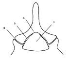
- FIG. 1 An axial cross-sectional view of a normal lumbar spinal canal is shown in FIG.
- the lumbar spinal canal 1 is a lumen surrounded by an intervertebral joint 2, a yellow ligament 3, a vertebral arch 4, an intervertebral disc, and the like, and a spinal cord or a dural tube or a nerve root passes through the lumen.
- Lumbar spinal canal stenosis is a disease that causes neurological symptoms in the lower limbs due to narrowing of the spinal canal due to enlargement of the facet joints and thickening of the yellow ligaments as shown in FIG.
- Posterior decompression which is a common surgical treatment for lumbar spinal canal stenosis, is a treatment method that expands the spinal canal by partially excising the bones of the vertebral arch and intervertebral joints and also excising the yellow ligament. .
- MED micro endoscopic spectroscopy
- a cylindrical outer tube having a diameter of less than 2 mm is installed on the back side of the vertebral arch, and the operation is completed under the endoscope within the outer tube.
- the spinous process and supraspinatus ligament are important as a lumbar posterior braking mechanism, these tissues can be preserved and the invasion of the surrounding muscles can be minimized.
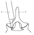
- the work is performed in the inner part of the cylindrical outer cylinder 5 which is a long and narrow cylinder. Therefore, the operation area is limited by the angle and position of the cylindrical outer cylinder. Since the spinous process 6 becomes an obstacle on the deployment side and the upper part of the cylindrical outer cylinder cannot be brought down to the spinous process side, the outer osteotomy on the deployment side is an angular problem, and there are many like the osteotomy line of the solid line 7. There was a problem that the decompression on the deployment side could not be sufficiently performed unless the bone was excised. If many bones are removed, many parts of the facet joints may be deleted or joints may be separated, which may increase instability.
- the present invention has an object of facilitating osteotomy in the bending direction of the blade in a bending osteotomy blade used when performing osteotomy of the lumbar spine for microinvasive surgery for lumbar spinal canal stenosis. To do.
- the main structure is composed of a blade portion, a handle having a gripping portion, and a hitting portion for hitting with a hammer, and the blade portion is bent with respect to the handle.
- the hitting portion is projected from the handle so that the hitting portion extends so as to extend on an extension line opposite to the direction of the blade.
- the point to be struck with a hammer is close to the straight line in the direction of the blade, even if the cutting edge of the osteotomy blade is not inserted into the bone, it can easily move in the direction of the blade, and the bone surface Less slipping.
- bone can be cut at an angle from the back, and many bones and joints can be preserved by more selectively resecting the spinal canal side.
- the main structure includes a blade portion 14, a handle 15 for gripping, and a hitting portion 16 for hitting a hammer, and the blade portion 14 is bent with respect to the handle 15.
- the handle 15 is composed of a grip 17 which is a thickened portion for gripping by hand and a shaft 18 which is continuous with the blade portion 14.
- the hit portion 16 is bent and continuous at the end of the handle 15 and has an arc-shaped shape with the tip of the blade portion 14 as the center point, and passes over an extension line opposite to the blade direction. It is a rigid structure with a length.
- the main structure includes a blade portion 19, a handle 20 for gripping, and a hitting portion 21 for hitting a hammer.
- the blade portion 19 is bent with respect to the handle 20.
- the handle 20 is composed of a grip 22 which is a thickened portion for gripping with a hand and a shaft 23 which is continuous with the blade portion 19.
- the hit portion 21 is a rigid structure that branches off from the lower end of the grip 22 of the handle 20 and extends opposite to the bending direction of the blade portion 19, and extends on the extension line in the direction opposite to the blade direction.
- a hitting point 24 is attached in the vicinity.
Abstract
Disclosed is a bendable osteotome (chisel) for use in cutting of bone during spine surgery under observation with use of a speculum, wherein cutting of bone can be easily conducted in the bending direction of a blade.
This osteotome is characterized in that a portion to be hammered is projected from the middle portion or the end of a handle and so extended along the extension line in the direction opposite to a blade so that the blade edge of the osteotome can easily advance in the direction of the blade even if the portion to be hammered is hammered in a state where the blade edge is not stabbed into a bone, and slippage thereof on the surface of the bone can be reduced.
Description
本発明は、腰部脊柱管狭窄症に対する微小侵襲手術において、腰椎の骨切りを行うときに用いられる屈曲骨切り刃(ノミ)に関するものである。
The present invention relates to a bent osteotomy blade (chisel) used when performing lumbar osteotomy in microinvasive surgery for lumbar spinal canal stenosis.
正常の腰部脊柱管の軸断面図を図1で示す。腰部脊柱管1は椎間関節2や黄色靭帯3、椎弓4、椎間板等により囲まれている管腔で中に脊髄もしくは硬膜管や神経根が通っている。腰部脊柱管狭窄症は、図2のような椎間関節の肥大や黄色靭帯の肥厚等による脊柱管の狭小化により下肢に神経症状を引き起こす疾患である。
An axial cross-sectional view of a normal lumbar spinal canal is shown in FIG. The lumbar spinal canal 1 is a lumen surrounded by an intervertebral joint 2, a yellow ligament 3, a vertebral arch 4, an intervertebral disc, and the like, and a spinal cord or a dural tube or a nerve root passes through the lumen. Lumbar spinal canal stenosis is a disease that causes neurological symptoms in the lower limbs due to narrowing of the spinal canal due to enlargement of the facet joints and thickening of the yellow ligaments as shown in FIG.
腰部脊柱管狭窄症に対する手術治療として一般的である後方除圧術とは、椎弓や椎間関節部の骨を部分的に切除し、黄色靭帯も切除して脊柱管を拡げる治療方法である。その後方除圧術のなかで、微小侵襲手術として近年普及している手術方法がMED(micro endoscopic discectomy)である。これは、2mm弱の直径の筒型外筒を椎弓の背側に設置して、その外筒内で内視鏡下に手術を完遂するものである。棘突起や棘上靭帯は腰椎後方制動機構として重要であるが、これらの組織を温存でき、その周囲の筋肉の侵襲も最小限にすることが可能である。
Posterior decompression, which is a common surgical treatment for lumbar spinal canal stenosis, is a treatment method that expands the spinal canal by partially excising the bones of the vertebral arch and intervertebral joints and also excising the yellow ligament. . Among the subsequent decompression procedures, MED (micro endoscopic spectroscopy) is a surgical method that has recently become widespread as a minimally invasive surgery. In this method, a cylindrical outer tube having a diameter of less than 2 mm is installed on the back side of the vertebral arch, and the operation is completed under the endoscope within the outer tube. Although the spinous process and supraspinatus ligament are important as a lumbar posterior braking mechanism, these tissues can be preserved and the invasion of the surrounding muscles can be minimized.
MEDでは図2で示すように細長い筒である筒型外筒5のなかの奥のほうで作業を行うことになるが、そのため筒型外筒の角度と位置により手術領域が限定される。展開側では棘突起6が障害となり筒型外筒の上方部を棘突起側に倒すことができないため、展開側の外側骨切りが角度的な問題で実線7の骨切り線のように多くの骨を切除しないと展開側の除圧が十分にできないという問題があった。多くの骨を切除してしまうと椎間関節の多くの部分が削除されたり、関節間分離を作ってしまったりして、不安定性を増加させてしまう危惧がある。
In the MED, as shown in FIG. 2, the work is performed in the inner part of the cylindrical outer cylinder 5 which is a long and narrow cylinder. Therefore, the operation area is limited by the angle and position of the cylindrical outer cylinder. Since the spinous process 6 becomes an obstacle on the deployment side and the upper part of the cylindrical outer cylinder cannot be brought down to the spinous process side, the outer osteotomy on the deployment side is an angular problem, and there are many like the osteotomy line of the solid line 7. There was a problem that the decompression on the deployment side could not be sufficiently performed unless the bone was excised. If many bones are removed, many parts of the facet joints may be deleted or joints may be separated, which may increase instability.
そこで、点線8の骨切り線のように骨をなるべく温存すべく、奥のほうで角度をつけて骨切りをして、より選択的な脊柱管側の骨切除を行うのが理想である。その目的で、刃が柄に対して屈曲したノミは既に存在する。しかし、ハンマーで叩打してノミを進めていくと屈曲した刃の方向に進まず、滑っていくことが多い。
Therefore, in order to preserve the bone as much as possible as shown by the dotted line 8, it is ideal to perform bone cutting on the spinal canal side more selectively by cutting the bone at an angle toward the back. For that purpose, there are already fleas whose blades are bent with respect to the handle. However, when you hit the hammer with a hammer and advance the chisel, it often does not move in the direction of the bent blade but slips.
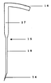
これは、図3に示すように骨切り刃を把持する柄9の端にハンマーで叩打するポイント10があり、刃11の方向の反対の延長線上12にないためである。骨切り刃は骨に刃先が刺入されていない状態で叩打されると、刃先と叩打するポイント10を結んだ線上13を進むことになり、刃の方向に進まず骨表面を滑ってしまう。
This is because, as shown in FIG. 3, there is a point 10 for hitting with a hammer at the end of the handle 9 that holds the osteotomy blade, and it is not on the extended line 12 opposite to the direction of the blade 11. When the bone cutting blade is struck in a state where the cutting edge is not inserted into the bone, the bone cutting blade travels on a line 13 connecting the cutting edge and the point 10 to be struck, and does not proceed in the direction of the blade but slides on the bone surface.
そこで、本発明は、腰部脊柱管狭窄症に対する微小侵襲手術に、腰椎の骨切りを行うときに用いられる屈曲骨切り刃において刃の屈曲方向に骨切りを行うことを容易にすることを目的とする。
Therefore, the present invention has an object of facilitating osteotomy in the bending direction of the blade in a bending osteotomy blade used when performing osteotomy of the lumbar spine for microinvasive surgery for lumbar spinal canal stenosis. To do.
主要構造は刃部と、把持する部分を有する柄と、ハンマーで打つための被叩打部で構成され、刃部は柄に対して屈曲している。被叩打部は柄から突設されて、刃の方向の反対の延長線上にかかるよう被叩打部が延設されているようにする。
The main structure is composed of a blade portion, a handle having a gripping portion, and a hitting portion for hitting with a hammer, and the blade portion is bent with respect to the handle. The hitting portion is projected from the handle so that the hitting portion extends so as to extend on an extension line opposite to the direction of the blade.
ハンマーで叩打するポイントが、刃の方向の直線上に近い位置にあるため、骨切り刃の刃先が骨に刺入されていない状態で叩打しても、刃の方向に進みやすく、骨表面を滑ってしまうことが少なくなる。
Because the point to be struck with a hammer is close to the straight line in the direction of the blade, even if the cutting edge of the osteotomy blade is not inserted into the bone, it can easily move in the direction of the blade, and the bone surface Less slipping.
そのため、奥のほうで角度をもって骨切りができ、脊柱管側をより選択的に骨切除することで骨や関節を多く温存できる。
Therefore, bone can be cut at an angle from the back, and many bones and joints can be preserved by more selectively resecting the spinal canal side.
本発明の実施形態1を図4に基づいて説明する。図4に図示するように、主要構造は刃部14と、把持するための柄15と、ハンマーを打つための被叩打部16で構成され、刃部14は柄15に対して屈曲している。柄15には手で把持するために太くなった部分であるグリップ17と刃部14に連続するシャフト18から構成される。被叩打部16は柄15の端にて屈曲して連続し、刃部14の先端を中心点とする弧を描いた形状となっていて、刃の方向の反対の延長線上を通過するような長さがある硬性構造物である。
Embodiment 1 of the present invention will be described with reference to FIG. As shown in FIG. 4, the main structure includes a blade portion 14, a handle 15 for gripping, and a hitting portion 16 for hitting a hammer, and the blade portion 14 is bent with respect to the handle 15. . The handle 15 is composed of a grip 17 which is a thickened portion for gripping by hand and a shaft 18 which is continuous with the blade portion 14. The hit portion 16 is bent and continuous at the end of the handle 15 and has an arc-shaped shape with the tip of the blade portion 14 as the center point, and passes over an extension line opposite to the blade direction. It is a rigid structure with a length.
被叩打部16の、刃の方向の反対の延長線上にあたる部分をハンマーで叩くと刃の方向に進みやすい。骨表面が硬く滑りやすい場合は、それよりさらに先の部分で叩打したり、また、あまり角度をつけたくなければ、より柄側を叩打したりして、刃の進む方向を微調整することが可能である。
When a portion of the hit portion 16 on the extension line opposite to the blade direction is hit with a hammer, the portion tends to advance in the blade direction. If the bone surface is hard and slippery, it is possible to finely adjust the direction in which the blade advances by tapping it further forward or by striking the handle side if you do not want to make an angle too much. Is possible.
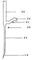
本発明の実施形態2を図5に基づいて説明する。主要構造は刃部19と、把持するための柄20と、ハンマーを打つための被叩打部21で構成され、刃部19は柄20に対して屈曲している。柄20には手で把持するために太くなった部分であるグリップ22と刃部19に連続するシャフト23から構成される。被叩打部21は、柄20のグリップ22の下端より分枝して、刃部19の屈曲方向とは反対に延設されている硬性構造物で、刃の方向とは反対の方向の延長線上付近に叩打点24が付属する。
A second embodiment of the present invention will be described with reference to FIG. The main structure includes a blade portion 19, a handle 20 for gripping, and a hitting portion 21 for hitting a hammer. The blade portion 19 is bent with respect to the handle 20. The handle 20 is composed of a grip 22 which is a thickened portion for gripping with a hand and a shaft 23 which is continuous with the blade portion 19. The hit portion 21 is a rigid structure that branches off from the lower end of the grip 22 of the handle 20 and extends opposite to the bending direction of the blade portion 19, and extends on the extension line in the direction opposite to the blade direction. A hitting point 24 is attached in the vicinity.
7 従来の展開側の外側骨切り線
8 理想的な展開側の外側骨切線
9 従来の骨切り刃の柄
10 従来の骨切り刃の叩打するポイント
11 従来の骨切り刃の刃
12 従来の骨切り刃の刃の方向の反対の延長線上
13 従来の骨切り刃の刃先と叩打するポイントを結んだ線上
14 実施形態1の刃部
15 実施形態1の柄
16 実施形態1の被叩打部
17 実施形態1のグリップ
18 実施形態1のシャフト
19 実施形態2の刃部
20 実施形態2の柄
21 実施形態2の被叩打部
22 実施形態2のグリップ
23 実施形態2のシャフト
24 実施形態2の叩打点 7 Conventional deployment-side outer osteotomy line 8 Ideal deployment-side outer osteotomy line 9 Conventionalosteotomy blade handle 10 Conventional osteotomy blade strike point 11 Conventional osteotomy blade 12 Conventional bone On the extension line opposite to the direction of the blade of the cutting blade 13 On the line connecting the cutting edge of the conventional bone cutting blade with the point to be struck 14 The blade part 15 of the first embodiment 15 The handle 16 of the first embodiment 16 The grip 18 of the form 1 The shaft 19 of the embodiment 1 The blade part 20 of the embodiment 2 The handle 21 of the embodiment 2 The hit part 22 of the embodiment 2 The grip 23 of the embodiment 2 The shaft 24 of the embodiment 2 The hitting point of the embodiment 2
8 理想的な展開側の外側骨切線
9 従来の骨切り刃の柄
10 従来の骨切り刃の叩打するポイント
11 従来の骨切り刃の刃
12 従来の骨切り刃の刃の方向の反対の延長線上
13 従来の骨切り刃の刃先と叩打するポイントを結んだ線上
14 実施形態1の刃部
15 実施形態1の柄
16 実施形態1の被叩打部
17 実施形態1のグリップ
18 実施形態1のシャフト
19 実施形態2の刃部
20 実施形態2の柄
21 実施形態2の被叩打部
22 実施形態2のグリップ
23 実施形態2のシャフト
24 実施形態2の叩打点 7 Conventional deployment-side outer osteotomy line 8 Ideal deployment-side outer osteotomy line 9 Conventional
Claims (3)
- 刃が柄に対して屈曲している手術用骨切り刃であって、ハンマーで打つための被叩打部を有し、被叩打部は、柄の途中もしくは端から設けられ、刃の方向の反対の延長線上付近へ被叩打部が延設されていることを特徴とする器具。 A surgical osteotomy blade whose blade is bent with respect to the handle, having a hitting portion for hitting with a hammer, the hitting portion being provided from the middle or end of the handle, opposite to the direction of the blade A device in which the hit portion is extended to the vicinity of the extension line of the.
- 請求項1記載の骨切り刃は、柄の軸の軸断平面への投影図において刃の方向とは反対側に被叩打部が位置することを特徴とする器具。 The osteotomy blade according to claim 1, wherein the hitting portion is located on the opposite side of the direction of the blade in the projected view of the axis of the handle onto the cutting plane.
- 請求項1、2いずれかに記載の骨切り刃は、被叩打部が、柄との脱着も可能とするように柄と嵌合する構造を有することを特徴とする器具。 The bone cutting blade according to any one of claims 1 and 2, wherein the hitting portion has a structure that fits with the handle so that the hitting portion can be detached from the handle.
Priority Applications (1)
| Application Number | Priority Date | Filing Date | Title |
|---|---|---|---|
| US13/127,198 US8828004B2 (en) | 2008-11-06 | 2011-05-02 | Surgical chisel |
Applications Claiming Priority (2)
| Application Number | Priority Date | Filing Date | Title |
|---|---|---|---|
| JP2008-309109 | 2008-11-06 | ||
| JP2008309109A JP4688923B2 (en) | 2008-11-06 | 2008-11-06 | Surgical osteotomy chisel |
Related Child Applications (1)
| Application Number | Title | Priority Date | Filing Date |
|---|---|---|---|
| US13127198 Continuation | 2011-05-02 |
Publications (1)
| Publication Number | Publication Date |
|---|---|
| WO2010053007A1 true WO2010053007A1 (en) | 2010-05-14 |
Family
ID=42152816
Family Applications (1)
| Application Number | Title | Priority Date | Filing Date |
|---|---|---|---|
| PCT/JP2009/068082 WO2010053007A1 (en) | 2008-11-06 | 2009-10-13 | Bendable osteotome |
Country Status (3)
| Country | Link |
|---|---|
| US (1) | US8828004B2 (en) |
| JP (1) | JP4688923B2 (en) |
| WO (1) | WO2010053007A1 (en) |
Cited By (2)
| Publication number | Priority date | Publication date | Assignee | Title |
|---|---|---|---|---|
| CN108125699A (en) * | 2018-02-01 | 2018-06-08 | 刘陈邦 | A kind of bent osteotome |
| WO2021229845A1 (en) * | 2020-05-15 | 2021-11-18 | 株式会社メドメタレックス | Thin-bladed chisel system |
Families Citing this family (3)
| Publication number | Priority date | Publication date | Assignee | Title |
|---|---|---|---|---|
| JP5785061B2 (en) * | 2011-10-26 | 2015-09-24 | 周 中村 | Osteotomy flea for percutaneous endoscopy |
| JP6281759B2 (en) * | 2013-07-10 | 2018-02-21 | オリンパステルモバイオマテリアル株式会社 | Osteotomy instrument |
| PL3492025T3 (en) | 2016-07-26 | 2022-05-23 | Olympus Terumo Biomaterials Corp. | Bone-cutting surgical instrument |
Citations (4)
| Publication number | Priority date | Publication date | Assignee | Title |
|---|---|---|---|---|
| JPS62189708U (en) * | 1986-05-23 | 1987-12-02 | ||
| JPH0563511U (en) * | 1992-02-13 | 1993-08-24 | 瑞穂医科工業株式会社 | Chisel for cutting cortical bone and chisel for deburring |
| JP2002535031A (en) * | 1999-01-19 | 2002-10-22 | ジンテーズ アクチエンゲゼルシャフト クール | Apparatus and method for locating and resecting bone |
| JP2002355254A (en) * | 2001-02-26 | 2002-12-10 | Ethicon Inc | Device to insert implant fixer |
Family Cites Families (3)
| Publication number | Priority date | Publication date | Assignee | Title |
|---|---|---|---|---|
| JPS5948607U (en) * | 1982-09-24 | 1984-03-31 | 株式会社フジタ医科器械 | Microprobes used in brain surgery, etc. |
| US4979574A (en) * | 1985-09-30 | 1990-12-25 | Lalama Craig R | Punch tool apparatus and method |
| US6962582B2 (en) * | 2002-12-30 | 2005-11-08 | C & J Holdings, Llc | Surgical instrument with near-axial geometry |
-
2008
- 2008-11-06 JP JP2008309109A patent/JP4688923B2/en active Active
-
2009
- 2009-10-13 WO PCT/JP2009/068082 patent/WO2010053007A1/en active Application Filing
-
2011
- 2011-05-02 US US13/127,198 patent/US8828004B2/en active Active
Patent Citations (4)
| Publication number | Priority date | Publication date | Assignee | Title |
|---|---|---|---|---|
| JPS62189708U (en) * | 1986-05-23 | 1987-12-02 | ||
| JPH0563511U (en) * | 1992-02-13 | 1993-08-24 | 瑞穂医科工業株式会社 | Chisel for cutting cortical bone and chisel for deburring |
| JP2002535031A (en) * | 1999-01-19 | 2002-10-22 | ジンテーズ アクチエンゲゼルシャフト クール | Apparatus and method for locating and resecting bone |
| JP2002355254A (en) * | 2001-02-26 | 2002-12-10 | Ethicon Inc | Device to insert implant fixer |
Cited By (5)
| Publication number | Priority date | Publication date | Assignee | Title |
|---|---|---|---|---|
| CN108125699A (en) * | 2018-02-01 | 2018-06-08 | 刘陈邦 | A kind of bent osteotome |
| CN108125699B (en) * | 2018-02-01 | 2024-03-22 | 山东医学高等专科学校 | Bendable bone chisel |
| WO2021229845A1 (en) * | 2020-05-15 | 2021-11-18 | 株式会社メドメタレックス | Thin-bladed chisel system |
| CN113966199A (en) * | 2020-05-15 | 2022-01-21 | 美德克斯医疗器材有限公司 | Thin-blade osteotome system |
| CN113966199B (en) * | 2020-05-15 | 2024-02-27 | 美德克斯医疗器材有限公司 | Thin blade osteotome system |
Also Published As
| Publication number | Publication date |
|---|---|
| US20110213370A1 (en) | 2011-09-01 |
| JP4688923B2 (en) | 2011-05-25 |
| JP2010110597A (en) | 2010-05-20 |
| US8828004B2 (en) | 2014-09-09 |
Similar Documents
| Publication | Publication Date | Title |
|---|---|---|
| USRE44896E1 (en) | Dissecting high speed burr for spinal surgery | |
| US9049986B2 (en) | Cannulotome | |
| US8623021B2 (en) | Facet joint reamer | |
| JP2010510042A (en) | Tools for use in the placement of bone repair devices | |
| US20080188854A1 (en) | Surgical Anchor Delivery System | |
| JP2010510841A5 (en) | ||
| US9232937B2 (en) | Rearchitecting the spine | |
| WO2010053007A1 (en) | Bendable osteotome | |
| US20140012261A1 (en) | Ultrasound Enhanced Selective Tissue Removal Method and Apparatus | |
| US8377087B2 (en) | Method and apparatus for spinal osteoligamentous resection | |
| US10548619B2 (en) | Selective spinal tissue removal apparatus and method | |
| US20130123786A1 (en) | Pedicle subtraction osteotomy device and methods | |
| JP6473439B2 (en) | Micro fracture pick | |
| JP2017511727A (en) | Method, implant and device for percutaneously dilating the spinal canal | |
| KR100674653B1 (en) | Living body tissue cutter for percutaneous endoscopic operation | |
| JP5785061B2 (en) | Osteotomy flea for percutaneous endoscopy | |
| JP5957166B2 (en) | Osteotomy flea for percutaneous endoscopy | |
| KR101152883B1 (en) | An operation device for herniation of intervertebral discs | |
| JP2010035669A (en) | Ostectomy rongeur in spinal endoscopic surgery | |
| JP7244232B2 (en) | Endo-retractor instrument for percutaneous endoscopic surgery of the spine | |
| US20160135862A1 (en) | Curved surgical tools | |
| CN217219130U (en) | Osteotome for cutting vertebral body posterior osteophyte | |
| KR200425767Y1 (en) | A chisel for operating implant | |
| JP3170888U (en) | Bone resection ronjour in spinal endoscopic surgery | |
| JP2020022553A5 (en) |
Legal Events
| Date | Code | Title | Description |
|---|---|---|---|
| 121 | Ep: the epo has been informed by wipo that ep was designated in this application |
Ref document number: 09824707 Country of ref document: EP Kind code of ref document: A1 |
|
| WWE | Wipo information: entry into national phase |
Ref document number: 13127198 Country of ref document: US |
|
| NENP | Non-entry into the national phase |
Ref country code: DE |
|
| 122 | Ep: pct application non-entry in european phase |
Ref document number: 09824707 Country of ref document: EP Kind code of ref document: A1 |