JP6473439B2 - Micro fracture pick - Google Patents
Micro fracture pick Download PDFInfo
- Publication number
- JP6473439B2 JP6473439B2 JP2016500993A JP2016500993A JP6473439B2 JP 6473439 B2 JP6473439 B2 JP 6473439B2 JP 2016500993 A JP2016500993 A JP 2016500993A JP 2016500993 A JP2016500993 A JP 2016500993A JP 6473439 B2 JP6473439 B2 JP 6473439B2
- Authority
- JP
- Japan
- Prior art keywords
- instrument
- tip
- shaft
- microfracture pick
- striking
- Prior art date
- Legal status (The legal status is an assumption and is not a legal conclusion. Google has not performed a legal analysis and makes no representation as to the accuracy of the status listed.)
- Active
Links
- 208000013201 Stress fracture Diseases 0.000 title claims description 169
- 230000007246 mechanism Effects 0.000 claims description 111
- 230000000295 complement effect Effects 0.000 claims description 54
- 238000000034 method Methods 0.000 claims description 15
- 238000009527 percussion Methods 0.000 claims 3
- 210000000988 bone and bone Anatomy 0.000 description 16
- 230000000638 stimulation Effects 0.000 description 13
- 210000000845 cartilage Anatomy 0.000 description 11
- 210000005065 subchondral bone plate Anatomy 0.000 description 7
- 210000000968 fibrocartilage Anatomy 0.000 description 6
- 210000003035 hyaline cartilage Anatomy 0.000 description 5
- 210000003484 anatomy Anatomy 0.000 description 3
- 210000003423 ankle Anatomy 0.000 description 3
- 238000005553 drilling Methods 0.000 description 3
- 208000037873 arthrodesis Diseases 0.000 description 2
- 230000015572 biosynthetic process Effects 0.000 description 2
- 238000007664 blowing Methods 0.000 description 2
- 230000003116 impacting effect Effects 0.000 description 2
- 210000004233 talus Anatomy 0.000 description 2
- 238000009825 accumulation Methods 0.000 description 1
- 239000000654 additive Substances 0.000 description 1
- 230000000996 additive effect Effects 0.000 description 1
- 238000005452 bending Methods 0.000 description 1
- 230000008901 benefit Effects 0.000 description 1
- 230000000740 bleeding effect Effects 0.000 description 1
- 239000008280 blood Substances 0.000 description 1
- 210000004369 blood Anatomy 0.000 description 1
- 230000036770 blood supply Effects 0.000 description 1
- 230000001054 cortical effect Effects 0.000 description 1
- 238000001035 drying Methods 0.000 description 1
- 239000012530 fluid Substances 0.000 description 1
- 210000004394 hip joint Anatomy 0.000 description 1
- 239000007943 implant Substances 0.000 description 1
- 208000014674 injury Diseases 0.000 description 1
- 230000002452 interceptive effect Effects 0.000 description 1
- 210000001503 joint Anatomy 0.000 description 1
- 210000003127 knee Anatomy 0.000 description 1
- 239000000463 material Substances 0.000 description 1
- 239000012567 medical material Substances 0.000 description 1
- 230000004048 modification Effects 0.000 description 1
- 238000012986 modification Methods 0.000 description 1
- 239000005445 natural material Substances 0.000 description 1
- 230000000399 orthopedic effect Effects 0.000 description 1
- 230000000149 penetrating effect Effects 0.000 description 1
- 238000010008 shearing Methods 0.000 description 1
- 229910001220 stainless steel Inorganic materials 0.000 description 1
- 239000010935 stainless steel Substances 0.000 description 1
- 230000001954 sterilising effect Effects 0.000 description 1
- 238000004659 sterilization and disinfection Methods 0.000 description 1
- 210000001519 tissue Anatomy 0.000 description 1
- 230000008733 trauma Effects 0.000 description 1
Images


Classifications
-
- A—HUMAN NECESSITIES
- A61—MEDICAL OR VETERINARY SCIENCE; HYGIENE
- A61B—DIAGNOSIS; SURGERY; IDENTIFICATION
- A61B17/00—Surgical instruments, devices or methods, e.g. tourniquets
- A61B17/16—Bone cutting, breaking or removal means other than saws, e.g. Osteoclasts; Drills or chisels for bones; Trepans
- A61B17/1604—Chisels; Rongeurs; Punches; Stamps
Description
本特許出願は、2013年3月14日に出願した「マイクロフラクチャーピック」という名称の米国仮特許出願第61/781,215号の優先権の利益を主張するものである。 This patent application claims the benefit of priority of US Provisional Patent Application No. 61 / 781,215, filed Mar. 14, 2013, entitled “Microfracture Pick”.
本出願は、一般に微小骨折刺激(microfracture stimulation)に関し、より詳細には、微小骨折刺激を行う際に使用する外科手術デバイスに関するものである。 This application relates generally to microfracture stimulation, and more particularly to a surgical device for use in performing microfracture stimulation.
人体では、関節(articulating joint)は、低い摩擦係数を持ち耐久性のある天然材料である硝子軟骨で覆われている。そのような硝子軟骨面は、ヒトが走るときに発生し得る負荷などの、繰り返される高度の負荷または外傷を受けると、経時的に損傷され得る。これは、特に、足首、膝、股関節部、および脊柱にある関節などの、圧縮力を受ける下半身の関節に当てはまる。 In the human body, articulating joints are covered with hyaline cartilage, which is a durable natural material with a low coefficient of friction. Such hyaline cartilage surfaces can be damaged over time when subjected to repeated high loads or trauma, such as the load that can occur when a person runs. This is especially true for lower body joints that are subject to compressive forces such as ankles, knees, hip joints, and joints in the spinal column.
近年、整形外科業界では、軟骨面の再建(resurfacing)が広く研究されている。軟骨面を再建する1つの既知の方法は、「微小骨折刺激」と呼ばれている。損傷した硝子軟骨を人工軟骨インプラントに交換する代わりに、損傷した軟骨を線維軟骨組織(本明細書では「線維軟骨」ともいう)に交換するために人体を刺激する微小骨折刺激が実行可能である。線維軟骨は、一般に硝子軟骨ほど頑強ではなく、典型的には硝子軟骨の摩擦係数と比較して高い摩擦係数を有する。それにもかかわらず、そのような線維軟骨は、多数の人々に疼痛の減少をもたらし、これらの人々がより活発なライフスタイルを想定することを可能にする。 In recent years, resurfacing of cartilage surfaces has been extensively studied in the orthopedic industry. One known method of reconstructing the cartilage surface is called “micro fracture stimulation”. Instead of replacing damaged hyaline cartilage with artificial cartilage implants, microfracture stimulation can be performed to stimulate the human body to replace damaged cartilage with fibrocartilage tissue (also referred to herein as “fibrocartilage”). . Fibrocartilage is generally not as robust as hyaline cartilage and typically has a higher coefficient of friction compared to that of hyaline cartilage. Nevertheless, such fibrocartilage results in reduced pain for a large number of people, allowing them to envision a more active lifestyle.
微小骨折刺激を行う際に使用する従来のマイクロフラクチャーピックは、ハンドルと、ハンドルに結合されたシャフトと、シャフトの先端部に配置された、尖鋭な、付加的には傾斜した、先端とを有する。例えば、従来のマイクロフラクチャーピックは、付加的には、シャフトの長手方向軸線に対して約20°、40°、60°、または90°の角度に屈曲した先端を有することができる。一般的な動作モードでは、微小骨折刺激は、最初に、損傷した軟骨の層の除去を必要とする。損傷した軟骨層の厚さは、典型的には、約1mmから6mmまでさまざまであり得る。次に、血液供給に達するように、除去した軟骨の層の領域において下にある軟骨下骨の中を通して、マイクロフラクチャーピックの鋭い先端を約2mm〜5mm動かす。次に、マイクロフラクチャーピックを除去し、小さな通路を軟骨下骨内に残す。マイクロフラクチャーピックは、典型的には、軟骨下骨を通る一連のそのような通路を作製するために使用される。その結果、最終的には、血液が一連の通路に沿って送られ、除去した軟骨層の領域において凝固し、最終的に線維軟骨の形成を生じさせる。 Conventional microfracture picks used in performing micro fracture stimulation have a handle, a shaft coupled to the handle, and a sharp, additionally slanted tip disposed at the tip of the shaft. . For example, a conventional microfracture pick can additionally have a tip bent at an angle of about 20 °, 40 °, 60 °, or 90 ° with respect to the longitudinal axis of the shaft. In a common mode of operation, microfracture stimulation first requires removal of the damaged cartilage layer. The thickness of the damaged cartilage layer can typically vary from about 1 mm to 6 mm. Next, the sharp tip of the microfracture pick is moved approximately 2 mm to 5 mm through the underlying subchondral bone in the area of the removed cartilage layer to reach the blood supply. The microfracture pick is then removed, leaving a small passage in the subchondral bone. Microfracture picks are typically used to create a series of such passages through the subchondral bone. The end result is that blood is sent along a series of passages and coagulates in the area of the removed cartilage layer, ultimately resulting in the formation of fibrocartilage.
外科医が、そのような従来のマイクロフラクチャーピックを使用して患者の軟骨下骨を穿孔するとき、外科医は、骨の硬い皮質層の中を通して鋭い先端を手動で前進させることに困難を覚えることがある。これは、問題となり得る。なぜなら、マイクロフラクチャーピックを骨内へと十分深く前進させないことによって、除去した軟骨層の領域内での線維軟骨の形成が妨げられることがあるからである。軟骨下骨の中を通してマイクロフラクチャーピックの鋭い先端を前進させる助けとなるように、外科医は、従来、ハンドルに下方への圧力を加えながら、ハンマーまたはマレットを使用してマイクロフラクチャーピックのハンドルの端を叩いてきた。しかしながら、ハンマーまたはマレットをそのように使用することによって、マイクロフラクチャーピックの先端に剪断力を生じさせ、潜在的には先端を破損させるまたは損傷させ得るので、ハンマーまたはマレットのそのような使用は欠点を有する。そのような破損した先端は、手術部位内で遊離体となることがあり、マイクロフラクチャー法の進捗の遅延を生じさせ得る。さらに、先端は骨面を削り、潜在的にはマイクロフラクチャーピックを周囲組織面に衝突させ、場合によっては損傷させ得る。 When a surgeon drills a patient's subchondral bone using such a conventional microfracture pick, the surgeon may find it difficult to manually advance a sharp tip through the hard cortical layer of bone. is there. This can be a problem. This is because, by not advancing the microfracture pick sufficiently deeply into the bone, fibrocartilage formation in the area of the removed cartilage layer may be hindered. To help advance the sharp tip of the microfracture pick through the subchondral bone, the surgeon has traditionally used a hammer or mallet to apply the downward pressure on the handle while using the hammer or mallet to the end of the microfracture pick handle. I've been hitting. However, such use of a hammer or mallet is disadvantageous because using such a hammer or mallet can cause shearing at the tip of the microfracture pick and potentially break or damage the tip. Have Such a broken tip can become loose in the surgical site and can cause a delay in the progress of the microfracture method. Furthermore, the tip can scrape the bone surface, potentially causing the microfracture pick to collide with the surrounding tissue surface and possibly damage it.
この問題に対処するために、従来のマイクロフラクチャーピックのシャフトまたはハンドルに受け板を直接的に取り付けることができる。そのような受け板は、典型的には、マイクロフラクチャーピックの鋭い先端の方向に垂直にシャフトまたはハンドルに取り付けられる。外科医が受け板をハンマーまたはマレットで叩くと、その結果生じる力によって、マイクロフラクチャーピックの先端が軟骨下骨を通って前進する。しかしながら、マイクロフラクチャーピックのシャフトまたはハンドルに受け板を直接的に取り付けることによって、マイクロフラクチャーピックが重くなり、扱いにくくなり得るので、マイクロフラクチャーピックのシャフトまたはハンドルに受け板を直接的に取り付けることも欠点を有する。患者の身体のすぐ近くで受け板を叩くという行為も、特に足首などの繊細な関節アクセス位置の近くで行うとき、問題となり得る。受け板はまた、手術部位への完全なアクセスを防止することによってマイクロフラクチャー法を妨害することがあり、潜在的に、外科医が骨の罹患した表面エリア全体を処置することを非常に困難にする。 To address this problem, the backing plate can be attached directly to the shaft or handle of a conventional microfracture pick. Such backing plates are typically attached to the shaft or handle perpendicular to the sharp tip of the microfracture pick. When the surgeon strikes the backing plate with a hammer or mallet, the resulting force advances the tip of the microfracture pick through the subchondral bone. However, attaching the backing plate directly to the shaft or handle of the microfracture pick can make the microfracture pick heavy and unwieldy, so it is also possible to attach the backing plate directly to the shaft or handle of the microfracture pick. Has drawbacks. The act of hitting the backing plate in the immediate vicinity of the patient's body can also be a problem, especially when performed near sensitive joint access locations such as ankles. The backing plate may also interfere with the microfracture method by preventing complete access to the surgical site, potentially making it very difficult for the surgeon to treat the entire affected surface area of the bone .
したがって、上記で説明した従来のマイクロフラクチャーピックの欠点の少なくともいくつかを回避するマイクロフラクチャーピックを有することが望ましい。 Therefore, it is desirable to have a microfracture pick that avoids at least some of the disadvantages of the conventional microfracture picks described above.
本出願によれば、ユーザーが骨の中を通してマイクロフラクチャーピックを前進させる助けとなるように構成された機構を有する外科手術デバイス(本明細書では「マイクロフラクチャーピック」という)が開示される。一見地においては、開示するマイクロフラクチャーピックは、基端部と先端部とを有する、シャフトなどの少なくとも1つの長尺部材(elongated member)と、シャフトの先端部に配置された、尖鋭な付加的には傾斜した先端と、シャフトの基端部に結合された付加的なハンドルと、シャフトまたはハンドルの1つまたは複数の位置に配置された、打撃器具(strike instrument)の相補形状機構(complementary feature)と係合する少なくとも1つの係合機構と、を含む。例示的な見地においては、打撃器具は、基端部と先端部とを有する、シャフトなどの少なくとも1つの長尺部材と、シャフトの先端部に配置された相補形状機構と、基端部とシャフトの基端部に結合された先端部とを有する付加的なハンドルと、シャフトまたはハンドルの基端部に配置された衝撃面と、を含む。さらなる例示的な見地においては、マイクロフラクチャーピックのシャフトまたはハンドル上に配置された係合機構は、レセプタクル(receptacle)として構成され、打撃器具の相補形状機構は、マイクロフラクチャーピックのレセプタクルと動作可能に係合するように構成される。他の例示的な見地においては、打撃器具の相補形状機構は、レセプタクルとして構成され、マイクロフラクチャーピックのシャフトまたはハンドル上に配置された係合機構は、打撃器具のレセプタクルと動作可能に係合するように構成される。 In accordance with this application, a surgical device (referred to herein as a “microfracture pick”) having a mechanism configured to help a user advance a microfracture pick through bone is disclosed. In one aspect, the disclosed microfracture pick has at least one elongated member, such as a shaft, having a proximal end and a distal end, and a sharp additional additive disposed at the distal end of the shaft. Complementary feature of a strike instrument, with an angled tip, an additional handle coupled to the proximal end of the shaft, and one or more positions on the shaft or handle And at least one engagement mechanism that engages. In an exemplary aspect, the striking instrument includes at least one elongate member, such as a shaft, having a proximal end and a distal end, a complementary feature disposed at the distal end of the shaft, and a proximal end and a shaft. An additional handle having a distal end coupled to the proximal end of the shaft and an impact surface disposed at the proximal end of the shaft or handle. In a further exemplary aspect, the engagement mechanism disposed on the shaft or handle of the microfracture pick is configured as a receptacle, and the complementary configuration mechanism of the strike instrument is operable with the receptacle of the microfracture pick. Configured to engage. In another exemplary aspect, the impact feature of the impact instrument is configured as a receptacle, and an engagement mechanism disposed on the shaft or handle of the microfracture pick is operatively engaged with the impact instrument receptacle. Configured as follows.
他の見地においては、基端部と先端部とハンドルの先端部近傍にある穴とを有する、ハンドルなどの長尺部材と、ハンドル内の穴を通過するように構成された打撃ピンと、打撃ピンの一端にある衝撃面と、打撃ピンの他端にある相補機構とを含む打撃器具を含む、マイクロフラクチャー法を行う際に使用するシステムが開示される。このシステムは、さらに、付加的なハンドルと、先端部を持つ、シャフトなどの長尺部材と、シャフトまたはハンドル上にある係合機構と、シャフトの先端部にある、尖鋭な、付加的には傾斜した先端とmを有する外科手術デバイスを含む。外科手術デバイスの係合機構は、打撃器具の相補形状機構と係合するように動作可能である。さらに、打撃器具のハンドルは、外科手術デバイスの長手方向軸線に対して略平行に配置され、相補形状機構との係合機構の係合を促進するように構成される。打撃器具の衝撃面を叩いたときには、外科手術デバイスのシャフトを介して先端によって変換される力が生成される。 In another aspect, a long member such as a handle having a proximal end, a distal end, and a hole near the distal end of the handle, a striking pin configured to pass through a hole in the handle, and a striking pin A system for use in performing a microfracture method is disclosed that includes a striking instrument that includes an impact surface at one end of the ball and a complementary mechanism at the other end of the striking pin. The system further includes an additional handle, an elongate member such as a shaft with a tip, an engagement mechanism on the shaft or handle, and a sharp, additionally, tip at the tip of the shaft. A surgical device having an angled tip and m. The engagement mechanism of the surgical device is operable to engage the complementary feature of the strike instrument. Further, the striking instrument handle is disposed generally parallel to the longitudinal axis of the surgical device and is configured to facilitate engagement of the engagement mechanism with the complementary feature. When the impact surface of the striking instrument is struck, a force is generated that is converted by the tip through the shaft of the surgical device.
さらなる見地においては、基端部と先端部とを持つ、シャフトなどの少なくとも1つの長尺部材と、シャフトの先端部に配置された、尖鋭な付加的には傾斜した先端と、シャフトの基端部に結合された付加的なハンドルと、シャフトまたはハンドルの1つまたは複数の場所に配置された、打撃器具の相補形状機構と係合する少なくとも1つの係合機構とを有する外科手術デバイスを準備することを含む、マイクロフラクチャー法を行う方法が開示される。この方法は、先端を所望の刺激点に位置決めすること、および、打撃器具の衝撃面を叩いて、シャフトを介して先端によって変換される力を生成することも含む。次に、先端が所望の刺激点から除去される。マイクロフラクチャー法を行う際の打撃器具のそのような使用によって、外科医は、微小骨折穿孔を所望の刺激点に、精度を向上させて置くことができる。打撃器具のそのような使用はまた、外科医が所望の微小骨折穿孔を達成するためにマイクロフラクチャーピックに手動で加えなければならない力の量を減少させる。 In a further aspect, at least one elongate member, such as a shaft, having a proximal end and a distal end, a sharp, optionally inclined distal end disposed at the distal end of the shaft, and a proximal end of the shaft Providing a surgical device having an additional handle coupled to the portion and at least one engagement mechanism disposed at one or more locations on the shaft or handle to engage a complementary feature of the strike instrument A method for performing a microfracture method is disclosed. The method also includes positioning the tip at a desired stimulation point and striking the impact surface of the strike instrument to generate a force that is translated by the tip through the shaft. The tip is then removed from the desired stimulation point. Such use of a striking instrument in performing a microfracture method allows a surgeon to place a microfracture perforation at a desired stimulation point with improved accuracy. Such use of the striking instrument also reduces the amount of force that the surgeon must manually apply to the microfracture pick to achieve the desired microfracture drilling.
基端部と先端部とを持つ長尺部材と、長尺部材の先端部に配置された、尖鋭な付加的には傾斜した先端と、長尺部材の1つまたは複数の位置に配置された、打撃器具の相補形状機構と係合する少なくとも1つの係合機構とを有するマイクロフラクチャーピックを提供することによって、ユーザーは、打撃器具を使用して、マイクロフラクチャーピックの長尺部材を介して先端によって変換される力を生成し、それによって、骨を通る先端の穿孔をより効果的にすることができる。その結果、使用中に先端を折る事例の数を減少させることができる。さらに、使用中に骨面に沿って先端を削る事例の数を実質的に無くすことができる。 A long member having a proximal end and a distal end, a sharp, additionally inclined tip disposed at the distal end of the long member, and disposed at one or more positions on the elongated member By providing a microfracture pick having at least one engagement mechanism that engages a complementary shape mechanism of the strike instrument, the user can use the strike instrument to tip through the elongated member of the microfracture pick Can generate a force that is converted by the tip, thereby making the tip drilling through the bone more effective. As a result, the number of cases where the tip is folded during use can be reduced. Furthermore, the number of cases in which the tip is cut along the bone surface during use can be substantially eliminated.
本発明の他の特徴、作用、および態様は、以下の「発明を実施するための形態」から明らかであろう。 Other features, actions, and aspects of the present invention will be apparent from the following Detailed Description.
本明細書に組み込まれ、その一部を構成する添付の図面は、本明細書で説明する1つまたは複数の実施形態を示し、「発明を実施するための形態」と併せて、これらの実施形態を説明する。 The accompanying drawings, which are incorporated in and constitute a part of this specification, illustrate one or more embodiments described herein, and together with the detailed description, describe these implementations. A form is demonstrated.
2013年3月14日に出願した「マイクロフラクチャーピック」という名称の米国仮特許出願第61/781,215号の開示が、参照によりその全体を本明細書に組み込まれる。 The disclosure of US Provisional Patent Application No. 61 / 781,215, filed Mar. 14, 2013, entitled “Microfracture Pick”, is hereby incorporated by reference in its entirety.
使用者が骨の中を通してマイクロフラクチャーピックを前進させる助けとなるように構成された機構を有するマイクロフラクチャーピックが開示される。このマイクロフラクチャーピックは、基端部と先端部とを持つシャフトと、シャフトの先端部にある、尖鋭な、付加的には傾斜した、先端と、シャフトの1つまたは複数の位置に配置された、打撃器具(strike instrument)の相補形状機構(complementary feature)と係合する少なくとも1つの係合機構と、を有する。打撃器具の衝撃面を叩くことによって、使用者は、マイクロフラクチャーピックのシャフトを介してその先端によって変換される力を生成し、それによって、骨を通る先端の貫通を、より効果的に行うことができる。 Disclosed is a microfracture pick having a mechanism configured to help a user advance the microfracture pick through bone. The microfracture pick is disposed at one or more positions of the shaft with a shaft having a proximal end and a distal end, a sharp, additionally inclined tip at the distal end of the shaft. At least one engagement mechanism that engages a complementary feature of a strike instrument. By striking the impact surface of the striking instrument, the user can generate a force that is converted by the tip through the shaft of the microfracture pick, thereby more effectively penetrating the tip through the bone. Can do.
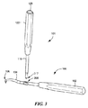
図1は、本出願によるマイクロフラクチャーピック100の例示的な実施形態を示す。図1に示されるように、マイクロフラクチャーピック100は、長尺ハンドル(elongated handle)102を含む基端部分と、基端部110と先端部112とを有する略長尺シャフト(generally elongated shaft)104を含む先端部分と、を有する。ハンドル102は、シャフト104の基端部110に結合される。マイクロフラクチャーピック100は、シャフト104の先端部112にある、尖鋭な、付加的には傾斜した先端106と、シャフト104の固定位置に配置された、打撃器具101の相補形状機構114と係合する係合機構108と、をさらに含む。打撃器具101は、基端部118と先端部120とを有するシャフト116を含むことができ、相補形状機構114は、シャフト116の先端部120にあってよい。打撃器具101は、基端部124とシャフト116の基端部118に結合された先端部126とを有するハンドル122と、ハンドル122の基端部124にある衝撃面128と、をさらに含むことができる。
FIG. 1 shows an exemplary embodiment of a
打撃器具101のハンドル122、シャフト116、および衝撃面128は、単一の構成要素として実施されてよいことに留意されたい。同様に、マイクロフラクチャーピック100のハンドル102およびシャフト104も、単一の構成要素として実施されてよい。マイクロフラクチャーピック100のシャフト104ならびに打撃器具101のシャフト116は、硬化ステンレス鋼などの機械加工された医療用材料または他の任意の適切な材料から作製可能であることにも留意されたい。さらに、マイクロフラクチャーピック100のハンドル102ならびに打撃器具101のハンドル122は、円筒状または他の任意の適切な形状を有することができる。いくつかの実施形態では、マイクロフラクチャーピック100のハンドル102は省略されてよい。さらに、先端106は、付加的には、マイクロフラクチャーピック100の長手方向軸線142に対して約20°、40°、60°、90°の角度、または他の任意の適切な角度で屈曲可能である。例えば、先端106は、付加的には、先端106をハンドル102の方へ後屈させることによって、長手方向軸線142に対して90°よりも大きい角度で屈曲可能である。
Note that the
使用中、マイクロフラクチャーピック100の鋭い先端106の方向133は、骨の面に対応することができる面130(図1を参照)に対して、角度αで位置合わせ可能である。打撃器具101の相補形状機構114がいったんマイクロフラクチャーピック100の係合機構108と係合されると、打撃器具101の長手方向軸線132は、面130に対してほぼ同じ角度αで位置合わせ可能である。したがって、使用者(たとえば外科医)が打撃器具101の衝撃面128を、ハンマー、マレット、または他の任意の適切な打撃用具で叩くとき、マイクロフラクチャーピック100のシャフト104を介して先端106によって変換される力134が生成される。
In use, the
図2は、ハンドル102と、シャフト104と、尖鋭な、付加的には傾斜した先端106と、レセプタクル(receptacle)208として構成される係合機構(図1、参照番号108を参照)とを含むマイクロフラクチャーピック100の斜視図を示す。この例示的な実施形態では、打撃器具101の相補形状機構114(図1を参照)は、マイクロフラクチャーピック100のレセプタクル208と動作可能に係合するように構成される。したがって、外科医が、骨の中を通してマイクロフラクチャーピック100の先端106を前進させることに困難を覚えた場合、外科医は、打撃器具101の相補形状機構114をマイクロフラクチャーピック100のレセプタクル208に挿入し、打撃器具101の衝撃面128をハンマーまたはマレットで1回または複数回叩いて、力を生成し、それによって、骨を通る先端106の前進を容易にすることができる。
FIG. 2 includes a
図3は、マイクロフラクチャーピック100および打撃器具101を示す斜視図を示し、相補形状機構(図1、参照番号114を参照)が、マイクロフラクチャーピック100のレセプタクル208に一時的または永久的に固定可能である付加的な突起(nub)317を含むように構成される。例えば、付加的な突起317は、または突起317のないシャフト116の一端は、ねじ止め、嵌合、レバーロック、カムロック、スナップ嵌合、セットネジ、テーパー嵌合、ルアーロック(テーパーを持つまたは持たない)、または他の任意の適切な機構を介して、レセプタクル208に一時的または永久的に固定可能である。
FIG. 3 shows a perspective view of the
図4は、レセプタクル208を含むマイクロフラクチャーピック100ならびに付加的な突起317を含む打撃器具101を示す断面図を示す。図4の断面図では、レセプタクル208は、実質的にマイクロフラクチャーピック100のシャフト104の内部にあるように示される。例えば、突起317は、オス型コネクタまたは他の任意の適切なコネクタとして構成可能であり、レセプタクル208は、メス型コネクタまたは他の任意の適切なコネクタとして構成可能である。いくつかの実施形態では、マイクロフラクチャーピック100は、オス型コネクタを含むように構成可能であり、打撃器具101は、マイクロフラクチャーピック100のオス型コネクタと係合するメス型コネクタを含むように構成可能である。そのようなオス型コネクタおよびメス型コネクタは、ねじ止め、嵌合、レバーロック、カムロック、スナップ嵌合、セットネジ、テーパー嵌合、ルアーロック(テーパーを持つまたは持たない)、または他の任意の適切な機構を介して、互いに一時的または永久的に固定可能である。さらに、レセプタクル208は、滅菌時および/または乾燥時の使用を目的とした、ならびに使用中のレセプタクル208内での流体の可能な蓄積を回避するための、外部ドレン穴409を含むように構成可能である。例えば、外部ドレン穴409は、約2mmの直径または他の任意の適切な直径を有することができる。
FIG. 4 shows a cross-sectional view of the
開示するマイクロフラクチャーピックの上記の例示的な実施形態について説明してきたが、他の代替可能な実施形態または変形形態が行われてもよい。例えば、マイクロフラクチャーピック100が、シャフト104の固定位置に配置された、打撃器具101の相補形状機構114と係合する係合機構108を含むことを、図1を参照して説明した。図5は、ハンドル502と、シャフト504と、尖鋭な、付加的には傾斜した先端506と、係合機構508と、を含むマイクロフラクチャーピック500の代替可能な実施形態を示す。図5に示されるように、シャフト504は、その長さの少なくとも一部分に沿ってチャネル(channel)540を内蔵するように構成され、係合機構508は、チャネル540と係合し、チャネル540に沿ってシャフト504の所望位置までスライドするように構成される。チャネル540は、シャフト504の長手方向軸線542と略平行である。さらに、係合機構508は、図2のレセプタクル208のようなレセプタクルを含むように構成可能である。係合機構508がいったんチャネル540に沿ってシャフト504の所望位置までスライドまたは移動させられると、係合機構508は、シャフト504のその位置に、少なくとも1つの係止部材(stop member)544によって一時的または永久的に固定可能であり、係止部材544は、図5に示されるように、係合機構508に隣接してチャネル540に挿入されてもよいし、または他の任意の適切な機構によって係合されてもよい。代替可能な実施形態では、係合機構508は、シャフト504の所望位置に一時的または永久的に固定可能である。さらなる代替可能な実施形態では、係合機構508は、マイクロフラクチャー法を行うために必要とされない場合、除去可能である。
While the above exemplary embodiments of the disclosed microfracture pick have been described, other alternative embodiments or variations may be made. For example, it has been described with reference to FIG. 1 that the
図6は、ハンドル602と、シャフト604と、尖鋭な、付加的には傾斜した先端606と、シャフト604の複数の固定位置にそれぞれ配置された複数の係合機構608.1、608.2、608.3とを含むマイクロフラクチャーピック600の代替可能な実施形態を示す。図6は、説明のために、シャフト604の3つのそのような係合機構を示す。しかしながら、マイクロフラクチャーピック600は、シャフト604のそれぞれの位置に配置された任意の適切な数の係合機構を含むことができることを理解されたい。例えば、複数の係合機構608.1、608.2、608.3のそれぞれは、図2のレセプタクル208のようなレセプタクルを含むように構成可能である。図6は、打撃器具601をさらに示し、打撃器具601では、相補形状機構は、シャフト604の複数の係合機構608.1、608.2、608.3のうち選択された1つに一時的または永久的に固定可能である付加的な突起617を、シャフト616の一端に含むように構成される。例えば、付加的な突起617、または突起617のないシャフト616の一端は、ねじ止め、嵌合、レバーロック、カムロック、スナップ嵌合、セットネジ、テーパー嵌合、ルアーロック(テーパーを持つまたは持たない)、または他の任意の適切な機構を介して、選択された係合機構608.1、608.2、または608.3に一時的または永久的に固定可能である。
FIG. 6 illustrates a
図7は、マイクロフラクチャーピック700の係合機構708と係合する相補形状機構714を含む打撃器具701の代替可能な実施形態を示す。図7に示されるように、打撃器具701は、基端部711と先端部713とハンドル722の先端部713近傍にある穴719とを有するハンドル722を含む。打撃器具701は、穴719をぴったりと通過するように構成された打撃ピン715と、打撃ピン715の一端にある相補形状機構714と、打撃ピン715の他端にある衝撃面728と、をさらに含む。打撃器具701のハンドル722、打撃ピン715、および衝撃面728は、単一の構成要素として実施可能であることに留意されたい。図7にさらに示されるように、マイクロフラクチャーピック700は、ハンドル702と、シャフト704と、シャフト704上にある係合機構708と、シャフト704の先端部にある、尖鋭な、付加的には傾斜した先端706と、を含む。打撃ピン715は、打撃器具701のハンドル722を通って穴719の中に一時的または永久的に固定可能であることに留意されたい。
FIG. 7 illustrates an alternative embodiment of a
図8は、マイクロフラクチャーピック700および打撃器具701を示し、打撃器具701の相補形状機構714は、付加的な突起717を含むように構成され、マイクロフラクチャーピック700の係合機構708は、レセプタクル709を含むように構成される。例えば、付加的な突起717、または突起717のない打撃ピン715の一端は、ねじ止め、嵌合、レバーロック、カムロック、スナップ嵌合、セットネジ、テーパー嵌合、ルアーロック(テーパーを持つまたは持たない)、または他の任意の適切な機構を介して、マイクロフラクチャーピック700のレセプタクル709に一時的または永久的に固定可能である。
FIG. 8 shows a
使用中、打撃器具701のハンドル722は、その長手方向軸線742に対して略平行にマイクロフラクチャーピック700のハンドル702に一時的または永久的に固定可能であり、それによって、外科医が、打撃器具701のハンドル722とマイクロフラクチャーピック700のハンドル702の両方を同じ手で持つことが可能になる。例えば、打撃器具701のハンドル722は、ねじ止め、嵌合、レバーロック、カムロック、スナップ嵌合、セットネジ、テーパー嵌合、ルアーロック(テーパーを持つまたは持たない)、差し込み式取り付け具(bayonet mount)、または他の任意の適切な機構を介して、マイクロフラクチャーピック700のハンドル702に一時的または永久的に固定可能である。さらに、打撃ピン715は、ハンドル722内の穴719を通過して、打撃器具701の突起717をマイクロフラクチャーピック700のレセプタクル709と係合させることができる。したがって、外科医が、骨の中を通してマイクロフラクチャーピック700の先端706を前進させることに困難を覚えた場合、外科医は、打撃ピン715の衝撃面728をハンマーまたはマレットで1回または複数回叩いて、力734を生成し、それによって、骨を通る先端706の前進を容易にすることができる。
During use, the
本明細書では、マイクロフラクチャーピックはそのシャフト上にレセプタクルを含むことができ、打撃器具は、レセプタクルと係合する付加的な突起をそのシャフト上に含むことができることについてさらに説明した。さらなる代替可能な実施形態では、マイクロフラクチャーピックは、そのシャフトの固定位置または移動可能位置に突起のように構成された少なくとも1つの係合機構を含むことができ、打撃器具は、そのシャフト上にレセプタクルのように構成された少なくとも1つの相補形状機構を含むことができる。例えば、打撃器具のシャフトのそのようなレセプタクルは、突起をマイクロフラクチャーピックのシャフトに載せるためのフォーク状構成を有することができる。さらに、マイクロフラクチャーピックは、あるいは、そのハンドル上に、打撃器具の相補形状機構と係合するための、突起またはオス型コネクタもしくはメス型コネクタなどのレセプタクルを含むことができる。同様に、打撃器具は、あるいは、そのハンドル上に、マイクロフラクチャーピックの係合機構と相補的に係合するための、突起またはオス型コネクタもしくはメス型コネクタなどのレセプタクルを含むことができる。 It has further been described herein that the microfracture pick can include a receptacle on its shaft, and the strike instrument can include additional protrusions on its shaft that engage the receptacle. In a further alternative embodiment, the microfracture pick can include at least one engagement mechanism configured as a protrusion in a fixed or movable position of the shaft, and the strike instrument is on the shaft. It may include at least one complementary feature configured like a receptacle. For example, such a receptacle of a striking instrument shaft may have a fork-like configuration for mounting a protrusion on the microfracture pick shaft. In addition, the microfracture pick may alternatively include a protrusion or receptacle, such as a male or female connector, on its handle for engaging the complementary feature of the striking instrument. Similarly, the striking instrument may alternatively include a protrusion or a receptacle, such as a male or female connector, on its handle for complementary engagement with the microfracture pick engagement mechanism.
また、本明細書では、マイクロフラクチャーピックは、そのシャフトのそれぞれの位置に配置された、打撃器具の相補形状機構と係合する複数の係合機構を含むことができることについても説明した。さらなる代替可能な実施形態では、マイクロフラクチャーピックの複数の係合機構は、平行または非平行な軸線を有するそれぞれのレセプタクルとして構成可能である。さらに、マイクロフラクチャーピックの複数の係合機構は、それぞれ、打撃器具の相補形状機構の異なる構成を受け入れるように構成可能である。 It has also been described herein that the microfracture pick can include a plurality of engagement features that engage the complementary shape features of the strike instrument disposed at respective positions on the shaft. In a further alternative embodiment, the plurality of engagement features of the microfracture pick can be configured as respective receptacles having parallel or non-parallel axes. Further, the plurality of engagement features of the microfracture pick can each be configured to accept a different configuration of the complementary shape mechanism of the strike instrument.
開示するマイクロフラクチャーピックを使用したマイクロフラクチャー法を行う方法について、以下で図9を参照して説明する。ブロック902に示されているように、この方法は、基端部と先端部とを持つシャフトと、シャフトの先端部に配置された、付加的には傾斜した先端と、シャフトの基端部に結合されたハンドルと、シャフトの1つまたは複数の位置に配置された、打撃器具の相補形状機構と係合する少なくとも1つの係合機構とを有するマイクロフラクチャーピックを準備することを含む。ブロック904に示されているように、先端は、所望の刺激点に位置している。例えば、先端を所望の刺激点に位置決めしながら、シャフトの少なくとも一部は、関節鏡視下カニューレに挿入可能である。ブロック906に示されているように、打撃器具の衝撃面は、ハンマーまたはマレットによって叩かれ、所望の刺激点でシャフトを介して先端によって変換される力を生成する。ブロック908に示されているように、その後、先端は、所望の刺激点から除去される。
A method for performing the microfracture method using the disclosed microfracture pick will be described below with reference to FIG. As shown in
図10〜図18は、本発明によるマイクロフラクチャーピックおよび打撃器具のさらなる代替可能な実施形態を示している。図10は、単一の構成部材として構成されたマイクロフラクチャーピック1000と打撃器具1001とを示している。図10に示すように、マイクロフラクチャーピック1000は、ハンドル1002と、シャフト1004と、シャフト1004の先端部に配置された尖鋭な、付加的には傾斜した先端1006と、を備えている。打撃器具1001は、打撃ピン1015と、この打撃ピン1015の一端に配置された衝撃面1028と、を備えている。マイクロフラクチャーピック1000および打撃器具1001が、単一の構成部材として構成されていることにより、打撃ピン1015は、マイクロフラクチャーピック1000のための、固定された打撃領域を提供することができる。図10の単一部材構成においては、打撃ピン1015の長手方向軸線1032を、先端1006の向き1033に対して、平行なものとし得ること、あるいは、非平行なものとし得ること、に注意されたい。また、1つまたは複数の代替可能な実施形態においては、マイクロフラクチャーピック1000のための1つまたは複数の打撃領域は、マイクロフラクチャーピック1000のシャフト1004上とマイクロフラクチャーピック1000のハンドル1002上とのいずれかにおいて、様々な位置においておよび/または様々な角度でもって、配置することができる。
Figures 10 to 18 show further alternative embodiments of the microfracture pick and hitting instrument according to the present invention. FIG. 10 shows a
図11においては、打撃器具1101は、マイクロフラクチャーピック1100の係合機構1108に対して係合するための、相補的なフォーク形状機構1114を備えている。マイクロフラクチャーピック1100は、ハンドル1102と、シャフト1104と、シャフト1104の先端部に配置された尖鋭な、付加的には傾斜した先端1106と、を備えている。打撃器具1101は、さらに、打撃ピン1115と、この打撃ピン1115の一端に配置された衝撃面1128と、を備えている。例えば、打撃器具1101のフォーク形状機構1114は、図示のように2つの突起を有することができる、あるいは、他の任意の適切な数の突起を有することができる。一実施形態においては、打撃器具1101は、マイクロフラクチャーピック1100のフォーク形状機構に対して係合するための、相補的形状機構を有することができる。打撃ピン1115の長手方向軸線1132を、先端1106の向き1133に対して、平行なものとし得ること、あるいは、非平行なものとし得ること、に注意されたい。
In FIG. 11, the
図12においては、打撃器具1201は、マイクロフラクチャーピック1200のスロット状「メス型」係合機構1208に対して係合するための、T字形状の(あるいは、他の同様の形状の)「オス型」相補形状機構1214を備えている。マイクロフラクチャーピック1200は、ハンドル1202と、シャフト1204と、シャフト1204の先端部に配置された尖鋭な、付加的には傾斜した先端1206と、を備えている。打撃器具1201は、さらに、打撃ピン1215と、この打撃ピン1215の一端に配置された衝撃面1228と、を備えている。一実施形態においては、打撃器具1201は、マイクロフラクチャーピック1200のT字形状の(あるいは、他の同様の形状の)「オス型」係合機構に対して係合するための、スロット状「メス型」相補形状機構を備えることができる。打撃ピン1215の長手方向軸線1232を、先端1206の向き1233に対して、平行なものとし得ること、あるいは、非平行なものとし得ること、に注意されたい。
In FIG. 12, the
図13においては、打撃器具1301は、マイクロフラクチャーピック1300のネジ山付き「メス型」係合機構1308に対して係合するための、ネジ山付き「オス型」相補形状機構1314を備えている。マイクロフラクチャーピック1300は、ハンドル1302と、シャフト1304と、シャフト1304の先端部に配置された尖鋭な、付加的には傾斜した先端1306と、を備えている。打撃器具1301は、さらに、打撃ピン1315と、この打撃ピン1315の一端に配置された衝撃面1328と、を備えている。一実施形態においては、打撃器具1301は、マイクロフラクチャーピック1300のネジ山付き「オス型」係合機構に対して係合するための、ネジ山付き「メス型」相補形状機構を備えることができる。例えば、ネジ山付き「オス型」相補形状機構1314およびネジ山付き「メス型」係合機構1308は、クォータターンやルアーロックや他の任意の適切な係合手段を提供するものとして構成することができる。打撃ピン1315の長手方向軸線1332を、先端1306の向き1333に対して、平行なものとし得ること、あるいは、非平行なものとし得ること、に注意されたい。
In FIG. 13, the
図14は、マイクロフラクチャーピック1400を示している。このマイクロフラクチャーピック1400は、ハンドル1402と、シャフト1404と、シャフト1404の先端部に配置された傾斜した先端1406と、打撃器具の相補形状機構(図示せず)に対して係合し得るよう構成された係合機構1408と、を備えている。図14に示すように、先端1406の傾斜角度は、角度θという任意の適切な範囲内において変更することができる。一実施形態においては、角度θは、90°よりも大きなものとすることができる。また、打撃器具は、任意の適切な角度γでもって係合機構1408に対して係合することができる。したがって、打撃器具を使用することにより、先端1406の向き1433に対して平行に、あるいは、先端1406に対して非平行に、角度γという範囲内において、長手方向軸線1432に沿った力を生成することができる。これにより、患者の解剖学的部分に対して干渉する可能性を回避することができる。
FIG. 14 shows a
図15aは、マイクロフラクチャーピック1500を示している。このマイクロフラクチャーピック1500は、ハンドル1502と、シャフト1504と、シャフト1504の先端部に配置された傾斜した先端1506と、打撃器具の相補形状機構(図示せず)に対して係合し得るよう構成された係合機構1508と、を備えている。図15aおよび図15bに示すように、先端1506の傾斜角度は、角度θという任意の適切な範囲内において(図15a参照)、および、角度θaという任意の適切な範囲内において(図15b参照)、変更することができる。また、打撃器具は、任意の適切な角度γでもって(図15a参照)、また、任意の適切な角度γaでもって(図15b参照)、係合機構1508に対して係合することができる。したがって、打撃器具を使用することにより、先端1506の向き1533に対して平行に、あるいは、先端1506に対して非平行に、角度γという範囲内においておよび/または角度γaという範囲内において、長手方向軸線1532に沿った力を生成することができる。これにより、様々な解剖学的部分に対してのアクセス性を改良することができる。
FIG. 15 a shows a
図16aは、マイクロフラクチャーピック1600を示している。このマイクロフラクチャーピック1600は、ハンドル1602と、シャフト1604と、シャフト1604の先端部に配置された付加的には傾斜した先端1606と、打撃器具の相補形状機構(図示せず)に対して係合し得るよう構成された係合機構1608と、を備えている。図16bは、図16aのマイクロフラクチャーピック1600を示す断面図である。図16aおよび図16bに示すように、係合機構1608は、ボールタイプの係合機構として構成することができる。これにより、例えばボールスイヴェル機構といったような、打撃器具の相補形状機構は、マイクロフラクチャーピック1600のボールタイプの係合機構内において浮遊または回転することができる。ボールタイプの係合機構として構成された係合機構1608が、全体的に円形である必要はないことに注意されたい。ボールタイプの係合機構として構成された係合機構1608は、部分的に円形のものとすることができ、これにより、1つまたは複数の方向において、打撃器具の移動を制限することができる。例えば、係合機構1608は、ディスク係合とすることができる、あるいは、他の任意の適切な円形形状とすることができる、あるいは、他の任意の適切な部分的な円形形状とすることができる。一実施形態においては、打撃器具の相補形状機構を、ボールタイプの係合機構として構成することができ、マイクロフラクチャーピック1600の係合機構1608を、ボールスイヴェル機構として構成することができる。
FIG. 16 a shows a
図17aは、打撃器具1701を示す断面図である。この打撃器具1701は、マイクロフラクチャーピック1700の係合機構1708に対して係合するための相補形状機構1714を備えている。マイクロフラクチャーピック1700は、ハンドル1702と、シャフト1704と、シャフト1704の先端部に配置された付加的には傾斜した先端1706と、を備えている。打撃器具1701は、さらに、打撃ピン1715と、この打撃ピン1715の一端に配置された衝撃面1791と、を備えている。打撃器具1701は、マイクロフラクチャーピック1700に対して係合し得るよう構成されている。打撃器具1701は、様々な解剖学的部分の穿孔を容易なものとし得るよう、逆向きで(矢印1795によって示されている)使用し得るよう構成されている。図17aに示すように、打撃器具1701は、スラップハンマー機構1790、および/または、マレットで衝撃するための衝撃面1791を備えることができる。図17bに示すように、係合機構1708は、容易なアクセスのためのC字形状開口を有するものとして構成することができる。
FIG. 17 a is a cross-sectional view showing a
図18は、打撃器具1801を示している。この打撃器具1801は、マイクロフラクチャーピック1800の係合機構1808に対して係合し得るよう適切に構成された相補形状機構1814を備えている。マイクロフラクチャーピック1800は、ハンドル1802と、シャフト1804と、シャフト1804の先端部に配置された付加的には傾斜した先端1806と、を備えている。打撃器具1801は、さらに、ハンドル1803と、シャフト1805と、シャフト1805上に配置されたマレットで衝撃するための衝撃領域1807と、を備えることができる。打撃器具1801の相補形状機構1814を、任意の適切な角度でもって、マイクロフラクチャーピック1800の係合機構1808に対して係合し得るよう構成することができることに注意されたい。
FIG. 18 shows a
軟骨面を再建する状況で使用するための、開示するマイクロフラクチャーピックの上記の例示的な実施形態について説明してきたが、これらの実施形態は、関節固定法において距骨下/距骨空間(足首)内の軟骨下骨を穿孔するためにも使用可能である。そのような関節固定法では、外科医は、典型的には、距骨下骨(subtalar bone)と距骨の両方の軟骨を除去し、マイクロフラクチャーピックを使用して複数の場所で距骨下骨および距骨を穿孔し、出血を促進する。その後、ねじを距骨下骨と距骨の間に送り、2つの骨を癒合させる。 Having described the above exemplary embodiments of the disclosed microfracture picks for use in situations where cartilage surfaces are being reconstructed, these embodiments can be used in arthrodesis in the subtalar / talar space (ankle). It can also be used to perforate the subchondral bone. In such arthrodesis, the surgeon typically removes both the subtalar bone and the talar cartilage and uses a microfracture pick to remove the subtalar and talus in multiple locations. Perforates and promotes bleeding. A screw is then sent between the subtalar and talus to coalesce the two bones.
本明細書で開示される発明概念から逸脱することなく上述のマイクロフラクチャーピックのさらなる修正および変形を加えることができることは、当業者には理解されるであろう。したがって、本発明は、添付の特許請求の範囲の精神および範囲を除いて限定されると見なされるべきではない。 Those skilled in the art will appreciate that further modifications and variations of the above-described microfracture picks can be made without departing from the inventive concepts disclosed herein. Accordingly, the invention should not be viewed as limited except as by the spirit and scope of the appended claims.
100 マイクロフラクチャーピック
101 打撃器具
102 ハンドル
104 シャフト
106 先端
108 係合機構
110 基端部
112 先端部
114 相補形状機構
116 シャフト
118 基端部
120 先端部
122 ハンドル
124 基端部
126 先端部
128 衝撃面
130 面
132 長手方向軸線
133 方向
134 力
142 長手方向軸線
208 レセプタクル
232 軸線
317 突起
409 外部ドレン穴
500 マイクロフラクチャーピック
502 ハンドル
504 シャフト
506 先端
508 係合機構
540 チャネル
542 長手方向軸線
544 係止部材
600 マイクロフラクチャーピック
601 打撃器具
602 ハンドル
604 シャフト
606 先端
616 シャフト
617 突起
700 マイクロフラクチャーピック
701 打撃器具
702 ハンドル
704 シャフト
706 先端
708 係合機構
709 レセプタクル
711 基端部
713 先端部
714 相補形状機構
715 打撃ピン
717 突起
719 穴
722 ハンドル
728 衝撃面
730 面
732 軸線
733 方向
734 力
742 長手方向軸線
1000 マイクロフラクチャーピック
1001 打撃器具
1002 ハンドル
1004 シャフト
1006 先端
1015 打撃ピン
1028 衝撃面
1100 マイクロフラクチャーピック
1101 打撃器具
1102 ハンドル
1104 シャフト
1106 先端
1108 係合機構
1114 相補的なフォーク形状機構
1115 打撃ピン
1128 衝撃面
1200 マイクロフラクチャーピック
1201 打撃器具
1202 ハンドル
1204 シャフト
1206 先端
1208 「メス型」係合機構
1214 「オス型」相補形状機構
1215 打撃ピン
1228 衝撃面
1300 マイクロフラクチャーピック
1301 打撃器具
1302 ハンドル
1304 シャフト
1306 先端
1308 「メス型」係合機構
1314 「オス型」相補形状機構
1315 打撃ピン
1328 衝撃面
1400 マイクロフラクチャーピック
1402 ハンドル
1404 シャフト
1406 先端
1408 係合機構
1500 マイクロフラクチャーピック
1502 ハンドル
1504 シャフト
1506 先端
1508 係合機構
1600 マイクロフラクチャーピック
1602 ハンドル
1604 シャフト
1606 先端
1608 係合機構
1700 マイクロフラクチャーピック
1701 打撃器具
1702 ハンドル
1704 シャフト
1706 先端
1708 係合機構
1714 相補形状機構
1715 打撃ピン
1791 衝撃面
1800 マイクロフラクチャーピック
1801 打撃器具
1802 ハンドル
1803 ハンドル
1804 シャフト
1805 シャフト
1806 先端
1807 衝撃領域
1808 係合機構
1814 相補形状機構
DESCRIPTION OF SYMBOLS 100 Microfracture pick 101 Impact tool 102 Handle 104 Shaft 106 Tip 108 Engagement mechanism 110 Base end part 112 Tip part 114 Complementary shaped mechanism 116 Shaft 118 Base end part 120 Tip part 122 Handle 124 Base end part 126 Tip part 128 Impact surface 130 Surface 132 longitudinal axis 133 direction 134 force 142 longitudinal axis 208 receptacle 232 axis 317 projection 409 external drain hole 500 microfracture pick 502 handle 504 shaft 506 tip 508 engaging mechanism 540 channel 542 longitudinal axis 544 locking member 600 microfracture 600 Pick 601 Striking instrument 602 Handle 604 Shaft 606 Tip 616 Shaft 617 Protrusion 700 Microfracture pin 701 Impact device 702 Handle 704 Shaft 706 Tip 708 Engagement mechanism 709 Receptacle 711 Base end 713 Tip 714 Complementary shape mechanism 715 Impact pin 717 Projection 719 Hole 722 Handle 728 Impact surface 730 Surface 732 Axis direction 732 Axis direction 732 Axis 1000 Microfracture pick 1001 Impact instrument 1002 Handle 1004 Shaft 1006 Tip 1015 Impact pin 1028 Impact surface 1100 Microfracture pick 1101 Impact instrument 1102 Handle 1104 Shaft 1106 Tip 1108 Impact mechanism 1114 Complementary fork-shaped mechanism 1128 Impact surface 1128 1200 Microfracture pick 1201 Blowing instrument 1202 Handle 1204 1206 tip 1208 "female type" engagement mechanism 1214 "male type" complementary shape mechanism 1215 impact pin 1228 impact surface 1300 microfracture pick 1301 impact instrument 1302 handle 1304 shaft 1306 tip 1308 "female type" engagement mechanism 1314 "male type" Complementary shape mechanism 1315 Impact pin 1328 Impact surface 1400 Microfracture pick 1402 Handle 1404 Shaft 1406 Tip 1408 Engagement mechanism 1500 Microfracture pick 1502 Handle 1504 Shaft 1506 Tip 1508 Engagement mechanism 1600 Microfracture pick 1602 Handle 1604 Shaft 1606 Combined mechanism 1700 Microfracture pick 1701 Blowing instrument 1702 Bundle 1704 shaft 1706 distal 1708 engagement mechanism 1714 complementary shape mechanism 1715 striker 1791 impact surface 1800 microfracture pick 1801 striking instrument 1802 handle 1803 Handle 1804 shaft 1805 shaft 1806 distal 1807 impact region 1808 engagement mechanism 1814 shape complementary mechanism
Claims (4)
打撃器具と、外科手術デバイスと、を具備してなり、
前記打撃器具が、
基端部と、先端部と、この先端部の近傍に配置されている穴と、を有した長尺部材と、
前記長尺部材の穴を挿通し得るよう構成されている打撃ピンと、
前記打撃ピンの少なくとも一端に配置されている衝撃面と、
を備え、
前記外科手術デバイスが、
先端部を有した長尺部材と、
前記長尺部材上に配置されている係合機構と、
前記長尺部材の前記先端部の近傍に配置されている先端と、
を備え、
前記打撃器具が、さらに、前記打撃ピンの他端に配置されている相補形状機構を備え、
前記外科手術デバイスの前記係合機構が、前記打撃器具の前記相補形状機構に対して係合し得るように動作し、
前記係合機構は、前記打撃器具に、前記先端の前記長尺部材の前記長手方向軸線に対する角度と略同じ角度であるアライメント角を提供し、
前記打撃器具の前記長尺部材が、前記外科手術デバイスの長手方向軸線に対して平行であるように配置され得るよう構成されており、これにより、前記相補形状機構に対しての前記係合機構の係合が可能とされており、
前記打撃器具の前記衝撃面を打撃した際には、前記外科手術デバイスの前記長尺部材を介して前記先端によって変換される力が生成される、
ことを特徴とするシステム。 A system for use in performing a microfracture method,
A striking instrument and a surgical device,
The hitting instrument is
A long member having a proximal end, a distal end, and a hole disposed in the vicinity of the distal end;
A striking pin configured to be able to pass through a hole in the elongated member;
An impact surface disposed on at least one end of the striking pin;
With
The surgical device is
A long member having a tip,
An engagement mechanism disposed on the elongate member;
A tip disposed in the vicinity of the tip of the elongated member;
With
The striking instrument further comprises a complementary shaped mechanism disposed at the other end of the striking pin;
The engagement mechanism of the surgical device is operable to engage with the complementary feature of the percussion instrument;
The engagement mechanism provides the striking instrument with an alignment angle that is substantially the same angle as the angle of the elongate member of the tip with respect to the longitudinal axis;
The elongate member of the percussion instrument is configured to be arranged to be parallel to a longitudinal axis of the surgical device, whereby the engagement mechanism for the complementary feature Can be engaged,
When striking the impact surface of the striking instrument, a force is generated that is converted by the tip through the elongated member of the surgical device,
A system characterized by that.
前記打撃器具の前記長尺部材が、前記外科手術デバイスに対して、少なくとも一時的に固定され得るよう構成されている、
ことを特徴とするシステム。 The system of claim 1 , wherein
The elongate member of the percussion instrument is configured to be at least temporarily secured to the surgical device;
A system characterized by that.
前記外科手術デバイスの前記係合機構が、メス型コネクタとして構成されており、
前記打撃器具の前記相補形状機構が、オス型コネクタとして構成されている、
ことを特徴とするシステム。 The system of claim 1 , wherein
The engagement mechanism of the surgical device is configured as a female connector;
The complementary shape mechanism of the impact device is configured as a male connector,
A system characterized by that.
前記外科手術デバイスの前記係合機構が、オス型コネクタとして構成されており、
前記打撃器具の前記相補形状機構が、メス型コネクタとして構成されている、
ことを特徴とするシステム。 The system of claim 1 , wherein
The engagement mechanism of the surgical device is configured as a male connector;
The complementary shape mechanism of the striking instrument is configured as a female connector,
A system characterized by that.
Applications Claiming Priority (3)
| Application Number | Priority Date | Filing Date | Title |
|---|---|---|---|
| US201361781215P | 2013-03-14 | 2013-03-14 | |
| US61/781,215 | 2013-03-14 | ||
| PCT/US2014/022537 WO2014150193A1 (en) | 2013-03-14 | 2014-03-10 | Microfracture pick |
Related Child Applications (1)
| Application Number | Title | Priority Date | Filing Date |
|---|---|---|---|
| JP2018240952A Division JP2019063582A (en) | 2013-03-14 | 2018-12-25 | Microfracture pick |
Publications (2)
| Publication Number | Publication Date |
|---|---|
| JP2016511099A JP2016511099A (en) | 2016-04-14 |
| JP6473439B2 true JP6473439B2 (en) | 2019-02-20 |
Family
ID=50382746
Family Applications (2)
| Application Number | Title | Priority Date | Filing Date |
|---|---|---|---|
| JP2016500993A Active JP6473439B2 (en) | 2013-03-14 | 2014-03-10 | Micro fracture pick |
| JP2018240952A Pending JP2019063582A (en) | 2013-03-14 | 2018-12-25 | Microfracture pick |
Family Applications After (1)
| Application Number | Title | Priority Date | Filing Date |
|---|---|---|---|
| JP2018240952A Pending JP2019063582A (en) | 2013-03-14 | 2018-12-25 | Microfracture pick |
Country Status (10)
| Country | Link |
|---|---|
| EP (1) | EP2967586B1 (en) |
| JP (2) | JP6473439B2 (en) |
| CN (1) | CN105025822B (en) |
| AU (1) | AU2014237438B2 (en) |
| BR (1) | BR112015022177A2 (en) |
| CA (1) | CA2903019A1 (en) |
| MX (1) | MX2015011810A (en) |
| RU (1) | RU2015142875A (en) |
| WO (1) | WO2014150193A1 (en) |
| ZA (1) | ZA201506162B (en) |
Families Citing this family (4)
| Publication number | Priority date | Publication date | Assignee | Title |
|---|---|---|---|---|
| CA3104813A1 (en) | 2018-07-03 | 2020-01-09 | Bosonic Ag | Device for perforating a dense bone layer |
| JP6781495B1 (en) * | 2020-05-15 | 2020-11-04 | 株式会社メドメタレックス | Thin blade only system |
| CN112826565A (en) * | 2020-12-31 | 2021-05-25 | 青岛市市立医院 | Penetrate more effective microfracture pick |
| CN115300039A (en) * | 2022-08-19 | 2022-11-08 | 浙江天松医疗器械股份有限公司 | Micro-fracture device |
Family Cites Families (12)
| Publication number | Priority date | Publication date | Assignee | Title |
|---|---|---|---|---|
| US4979574A (en) * | 1985-09-30 | 1990-12-25 | Lalama Craig R | Punch tool apparatus and method |
| US5312413A (en) * | 1991-07-17 | 1994-05-17 | Eaton Alexander M | Instrumentation for ophthalmic surgery and method of using the same |
| JP3297042B1 (en) * | 2001-08-20 | 2002-07-02 | 輝夫 伊藤 | Oral implant treatment bone only |
| US6991633B2 (en) * | 2001-10-10 | 2006-01-31 | Codman & Shurtleff, Inc. | Rongeur with detachable crossbar |
| US6960214B2 (en) * | 2002-10-15 | 2005-11-01 | Zimmer Austin, Inc. | Method for performing automated microfracture |
| WO2007106895A2 (en) * | 2006-03-15 | 2007-09-20 | Smith & Nephew, Inc. | Microfracture pick |
| WO2008045902A2 (en) * | 2006-10-08 | 2008-04-17 | Ira Kirschenbaum | Cannulated apparatus and method relating to microfracture and revascularization methodologies |
| WO2009129272A2 (en) * | 2008-04-15 | 2009-10-22 | Lonnie Paulos | Tissue microfracture apparatus and methods of use |
| AU2010278867B2 (en) * | 2009-07-30 | 2015-10-01 | Smith & Nephew, Inc. | Instrument for creating microfractures in a bone |
| US20120071876A1 (en) * | 2010-09-17 | 2012-03-22 | Stoll E Jordan | Microfracture awl |
| US8721648B2 (en) * | 2011-05-13 | 2014-05-13 | Biomet Manufacturing, Llc | Microfracture pick for femoral head |
| BR112014018644A2 (en) * | 2012-01-29 | 2017-07-04 | Smith & Nephew Inc | microfract hole punch |
-
2014
- 2014-03-10 MX MX2015011810A patent/MX2015011810A/en unknown
- 2014-03-10 RU RU2015142875A patent/RU2015142875A/en not_active Application Discontinuation
- 2014-03-10 BR BR112015022177A patent/BR112015022177A2/en not_active IP Right Cessation
- 2014-03-10 AU AU2014237438A patent/AU2014237438B2/en not_active Expired - Fee Related
- 2014-03-10 CN CN201480015126.4A patent/CN105025822B/en active Active
- 2014-03-10 CA CA2903019A patent/CA2903019A1/en not_active Abandoned
- 2014-03-10 WO PCT/US2014/022537 patent/WO2014150193A1/en active Application Filing
- 2014-03-10 JP JP2016500993A patent/JP6473439B2/en active Active
- 2014-03-10 EP EP14713009.0A patent/EP2967586B1/en active Active
-
2015
- 2015-08-24 ZA ZA2015/06162A patent/ZA201506162B/en unknown
-
2018
- 2018-12-25 JP JP2018240952A patent/JP2019063582A/en active Pending
Also Published As
| Publication number | Publication date |
|---|---|
| CA2903019A1 (en) | 2014-09-25 |
| ZA201506162B (en) | 2017-03-29 |
| JP2019063582A (en) | 2019-04-25 |
| JP2016511099A (en) | 2016-04-14 |
| MX2015011810A (en) | 2016-08-11 |
| CN105025822A (en) | 2015-11-04 |
| CN105025822B (en) | 2018-11-23 |
| EP2967586A1 (en) | 2016-01-20 |
| AU2014237438B2 (en) | 2018-11-29 |
| BR112015022177A2 (en) | 2017-07-18 |
| RU2015142875A (en) | 2017-04-18 |
| AU2014237438A1 (en) | 2015-09-17 |
| EP2967586B1 (en) | 2023-03-01 |
| WO2014150193A1 (en) | 2014-09-25 |
Similar Documents
| Publication | Publication Date | Title |
|---|---|---|
| US9895179B2 (en) | Intramedullary fixation devices | |
| US11666345B2 (en) | Intramedullary nail alignment guides, fixation guides, devices, systems, and methods of use | |
| JP6571334B2 (en) | Micro fracture pick | |
| US9259230B2 (en) | Microfracture pick | |
| US8409250B2 (en) | Meniscal repair system and method | |
| US7837713B2 (en) | Methods and surgical kits for minimally-invasive facet joint fusion | |
| US9357985B2 (en) | Method for accessing a spinal facet joint | |
| US7942881B2 (en) | Microfracture pick | |
| JP2019063582A (en) | Microfracture pick | |
| US9655630B2 (en) | Methods and devices for forming holes in bone to stimulate bone growth | |
| CN101296666A (en) | Spinal fixation system instrumentation and method of using same | |
| CN103209650A (en) | Cannulotome | |
| WO2007056379A9 (en) | Application of therapy aligned to an internal target path | |
| JP2008012080A (en) | Intramedullary nail and orthopedic surgical instrument set |
Legal Events
| Date | Code | Title | Description |
|---|---|---|---|
| A621 | Written request for application examination |
Free format text: JAPANESE INTERMEDIATE CODE: A621 Effective date: 20170309 |
|
| A131 | Notification of reasons for refusal |
Free format text: JAPANESE INTERMEDIATE CODE: A131 Effective date: 20180129 |
|
| A977 | Report on retrieval |
Free format text: JAPANESE INTERMEDIATE CODE: A971007 Effective date: 20180131 |
|
| A521 | Request for written amendment filed |
Free format text: JAPANESE INTERMEDIATE CODE: A523 Effective date: 20180420 |
|
| A131 | Notification of reasons for refusal |
Free format text: JAPANESE INTERMEDIATE CODE: A131 Effective date: 20180514 |
|
| A521 | Request for written amendment filed |
Free format text: JAPANESE INTERMEDIATE CODE: A523 Effective date: 20180809 |
|
| A02 | Decision of refusal |
Free format text: JAPANESE INTERMEDIATE CODE: A02 Effective date: 20180827 |
|
| A521 | Request for written amendment filed |
Free format text: JAPANESE INTERMEDIATE CODE: A523 Effective date: 20181225 |
|
| A911 | Transfer to examiner for re-examination before appeal (zenchi) |
Free format text: JAPANESE INTERMEDIATE CODE: A911 Effective date: 20190107 |
|
| TRDD | Decision of grant or rejection written | ||
| A01 | Written decision to grant a patent or to grant a registration (utility model) |
Free format text: JAPANESE INTERMEDIATE CODE: A01 Effective date: 20190121 |
|
| A61 | First payment of annual fees (during grant procedure) |
Free format text: JAPANESE INTERMEDIATE CODE: A61 Effective date: 20190125 |
|
| R150 | Certificate of patent or registration of utility model |
Ref document number: 6473439 Country of ref document: JP Free format text: JAPANESE INTERMEDIATE CODE: R150 |
|
| R250 | Receipt of annual fees |
Free format text: JAPANESE INTERMEDIATE CODE: R250 |
|
| R250 | Receipt of annual fees |
Free format text: JAPANESE INTERMEDIATE CODE: R250 |
|
| R250 | Receipt of annual fees |
Free format text: JAPANESE INTERMEDIATE CODE: R250 |