WO2010052937A1 - 放射能汚染検査装置及び検査方法 - Google Patents
放射能汚染検査装置及び検査方法 Download PDFInfo
- Publication number
- WO2010052937A1 WO2010052937A1 PCT/JP2009/005982 JP2009005982W WO2010052937A1 WO 2010052937 A1 WO2010052937 A1 WO 2010052937A1 JP 2009005982 W JP2009005982 W JP 2009005982W WO 2010052937 A1 WO2010052937 A1 WO 2010052937A1
- Authority
- WO
- WIPO (PCT)
- Prior art keywords
- radioactive contamination
- hole
- radiation detection
- detection unit
- inspection
- Prior art date
- Legal status (The legal status is an assumption and is not a legal conclusion. Google has not performed a legal analysis and makes no representation as to the accuracy of the status listed.)
- Ceased
Links
Images



Classifications
-
- G—PHYSICS
- G01—MEASURING; TESTING
- G01T—MEASUREMENT OF NUCLEAR OR X-RADIATION
- G01T1/00—Measuring X-radiation, gamma radiation, corpuscular radiation, or cosmic radiation
- G01T1/16—Measuring radiation intensity
- G01T1/169—Exploration, location of contaminated surface areas
-
- G—PHYSICS
- G21—NUCLEAR PHYSICS; NUCLEAR ENGINEERING
- G21F—PROTECTION AGAINST X-RADIATION, GAMMA RADIATION, CORPUSCULAR RADIATION OR PARTICLE BOMBARDMENT; TREATING RADIOACTIVELY CONTAMINATED MATERIAL; DECONTAMINATION ARRANGEMENTS THEREFOR
- G21F9/00—Treating radioactively contaminated material; Decontamination arrangements therefor
- G21F9/001—Decontamination of contaminated objects, apparatus, clothes, food; Preventing contamination thereof
Definitions
- the present invention relates to a radioactive contamination inspection apparatus and an inspection method, and more particularly to a radioactive contamination inspection apparatus and an inspection method for performing an radioactive contamination inspection of an inspection object having a narrow surrounding space.
- the gap between the nozzle blades to be inspected is very narrow, it is difficult to inspect residual radiation from nozzle blades after decontamination by blasting etc. using a commercially available radioactive contamination inspection device. Yes, the retirement work period was prolonged.
- the distance ⁇ between the nozzle blades of the turbine rotor is very narrow, about 3.9 mm to 24 mm.
- the inside of the through-hole and the non-through-hole formed in the horizontal joint surface of the turbine nozzle diaphragm are also very narrow.
- the turbine rotor is disassembled and extracted so as to enable measurement of the residual radiation of the inspection object having a narrow surrounding space
- the nozzle diaphragm is divided into three types of outer ring, inner ring and nozzle blades and disassembled.
- the method of inspection was common. Since the nozzle blades are cast in the outer ring and the inner ring, there is only a method of mechanically cutting or fusing in order to disassemble the nozzle blade.
- the nozzle diaphragm incorporating the nozzle blades mentioned above has 8 stages x 1 in the high pressure turbine and 9 stages x 3 in the low pressure turbine in one plant of 1100 MWh class, and the number of nozzle plates is about 10,000. By making it possible to store all of them in the same shape without cutting them, it was a problem to shorten the process, save resources such as time, labor, and electric power and reduce the installation cost of equipment.
- Patent Document 1 discloses a radioactive contamination inspection apparatus that can easily perform an radioactive contamination inspection on the inner surface of a tube. That is, a radiation configured by attaching a scintillator portion or the like to a rod-shaped transparent light guide portion extending from a cylindrical photoelectric conversion portion, and mounting a light shielding portion that transmits radiation outside but blocks light. A detection unit is disclosed. However, the radiation detection unit shown in Patent Document 1 is for measuring radiation on the inner surface of a pipe, and is used for inspecting an inspection object having a narrow through-hole, a non-through hole, or a surrounding space. Was accompanied by difficulties.
- the present application facilitates radiation detection of a through-hole, a hole that does not penetrate, or an inspection object with a narrow surrounding space without disassembling, cutting, or melting the inspection object. It aims at providing the radioactive contamination inspection apparatus or inspection method which enables this.
- a radioactive contamination inspection apparatus includes a radiation detection unit, a photoelectric conversion unit that converts light generated by the radiation detection unit into electricity, and a signal processing unit connected to the photoelectric conversion unit, Is provided.
- the radiation detection unit of the present embodiment includes a light guide bar having a rectangular cross section and a quadrangular prism shape, and a scintillator attached to only two adjacent side surfaces of the four side surfaces of the light guide bar.
- the light guide bar has a square cross section, and a scintillator is further attached to the tip of the light guide bar.
- the scintillator is covered with a lattice protection member.
- the scintillator attached to the tip of a light guide bar having a square cross section and the scintillator attached to the two adjacent side surfaces are covered with a lattice-shaped protective member.
- the lattice protection member is formed of stainless steel.
- a radiation detection unit having a square cross section of the light guide bar is inserted into a through hole, and the radioactive contamination of the half surface of the inner surface of the through hole is inspected. To do.
- This method further inverts the radiation detection part about its longitudinal axis, and inspects the remaining surface of the inner surface of the through hole for radioactive contamination.
- the light guide bar has a square cross-section and a scintillator disposed on the bottom surface of the radiation detection unit is inserted into the non-through hole, and the non-penetration is performed. Inspect for radioactive contamination on the surface of at least half of the inner surface of the hole. This method further inverts the radiation detector around its longitudinal axis, and inspects the remaining surface of the inner surface of the non-through hole for radioactive contamination.
- a radiation detection unit having a rectangular cross section of the light guide bar is inserted into a narrow space around the inspection object, and one of the inspection objects is Inspect the surface for radioactive contamination.
- the radiation detection unit is further inverted about its longitudinal axis, and the other surface of the inspection object is inspected for radioactive contamination.
- a radioactive contamination inspection apparatus or inspection method is provided.
- a general configuration of a radioactive contamination inspection apparatus for example, a radiation detection unit using a scintillator as shown in the above-mentioned Patent Document 1, and a photoelectric conversion unit that photoelectrically converts this detection signal by an electron multiplier Detailed description of the signal processing unit and the like will be omitted, and the characteristic items of the present application will be described.
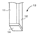
- FIG. 1 shows a radiation detection unit according to an embodiment of the present invention.
- the light guide bar 11 of the radiation detection unit 10 shown in FIG. 1 is a regular quadrangular prism having a rod shape and a square cross section.
- a scintillator 12 is disposed on two adjacent side surfaces of the light guide bar 11.
- the radiation detection unit 10 is suitable for inspecting radioactive contamination on the inner surface of a through hole such as a screw hole.
- FIG. 2 shows a radiation detection unit according to another embodiment of the present invention.
- the scintillator 14 is also provided at the tip of the light guide bar 11 in addition to the two adjacent side surfaces where the scintillator 12 is arranged in the radiation detection unit 10 shown in FIG. 1.
- the radiation detection unit 13 is suitable for inspecting radioactive contamination on the inner surface of a non-through hole such as a screw hole having a bottom.
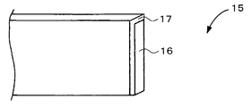
- FIG. 3 shows a radiation detection unit according to still another embodiment of the present invention.
- the light guide bar 16 is a rectangular column having a flat plate shape and a rectangular cross section.
- Scintillators 17 are arranged on two side surfaces including the long side and the short side adjacent to each other on the bottom surface of the radiation detection unit 15.
- the thickness of the scintillator 17 can be set to 2 mm, and the thickness of the light guide bar 16 can be set to 4 mm.
- the thickness of the radiation detection unit 15 is 6 mm, and the flat plate-like radiation detection unit 15 can be inserted into a narrow portion.
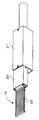
- FIGS. 4 and 5 show the configuration of a radiation detection unit that covers a scintillator with a lattice-shaped protective member according to another embodiment of the present invention.
- the protection member is provided to prevent the scintillator of the rod-shaped or flat-plate-shaped radiation detection unit from being contaminated or damaged by impact or contact with other members.
- FIG. 4 shows a protection member 19 formed in a cross shape for mechanically protecting the scintillator 14 disposed at the tip of the rod-shaped radiation detection unit 13 shown in FIG. 2 and the scintillator 12 disposed on the side surface mechanically.
- a grid-like protective member 18 for protection is shown.
- the cross-shaped or grid-shaped protective member the cross-shaped or grid-shaped part is formed of a strong member, and the other part is a cavity.
- the cross-shaped or grid-like shape is an example, and the shape is not limited, and other mesh-like shapes can be applied.
- FIG. 4 also shows the photoelectric conversion unit 20 and the signal processing unit 21.
- the photoelectric conversion unit 20 converts light generated when radiation is incident on the radiation detection unit 13 into an electrical signal.
- the signal processing unit 21 is connected to the photoelectric conversion unit 20 and performs processing such as wave height analysis on the electrical signal output from the photoelectric conversion unit 20.
- the rod-shaped radiation detector 10 shown in FIG. 1 is covered with a grid-like protective member, but the scintillator 14 disposed at the tip of the rod-shaped radiation detector 13 shown in FIG. 4 is protected.
- the configuration is almost the same as the configuration excluding the protection member 19.
- FIG. 5 shows a configuration in which the outer periphery of the plate-like radiation detector 15 shown in FIG. FIG. 5 also shows a photoelectric conversion unit 20 ′ and a signal processing unit 21 ′.
- the functions of the photoelectric conversion unit 20 ′ and the signal processing unit 21 ′ are the same as the functions of the photoelectric conversion unit 20 and the signal processing unit 21, respectively.
- the above-mentioned cross-shaped protection member 19 and the lattice-like protection members 18 and 23 are made of stainless steel, and the opening ratio is about 85%.
- the value of the aperture ratio is a value that makes it possible to minimize the radiation shielding by stainless steel and maintain the anti-shock function.
- the scintillators are arranged only on two adjacent side surfaces among the four side surfaces of the quadrangular prism as described above. Therefore, the only surface that can be inspected at one time among the surfaces of the object to be inspected is the surface facing the two adjacent side surfaces where the scintillator of the radiation detector is arranged, and the other surfaces should be inspected simultaneously. I can't.
- scintillators are arranged on all side surfaces of the rectangular column, it is possible to inspect radioactive contamination all around the same at the same time.
- scintillators are arranged only on the two adjacent side surfaces.
- the radiation detection operation of the inspection object having a narrow through hole or a non-through hole or a surrounding space is simplified, and the processing method is simplified.
- the above-described radioactive contamination according to the embodiment according to the present application is taken as an example of a screw hole that penetrates and a screw hole that is a non-through hole with a bottom.
- a method for performing radioactive contamination inspection using an inspection apparatus will be described.
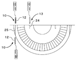
- the radiation detection unit 10 shown in FIG. 1 is inserted into the through hole 25 from the upper side of FIG.
- the scintillators 12 of the radiation detection unit 10 are arranged on the right side and the back surface of the radiation detection unit 10 in FIG. 6.
- the radioactive contamination inspection is performed on the right side and the back surface of the inner surface of the through hole 25 in FIG. If the dimension of the scintillator 12 in the longitudinal direction is equal to or greater than the length of the through-hole 25, the inspection of radioactive contamination for the half of the inner surface of the through-hole 25 is completed.
- the radiation detection unit 10 is inverted about its longitudinal axis.
- the scintillators 12 of the radiation detection unit 10 are located on the left side and the front surface of the radiation detection unit 10 in FIG. 6.
- the radiation detection unit 10 is again inserted into the through hole 25 from the upper side of FIG.
- inspects using the radiation detection part 10 was described, it can also test
- the scintillator 14 and the protection member 19 disposed at the tip of the radiation detection unit are not necessarily required.
- the radiation detector is inserted again from below, and the same method as the inspection from above is used. Perform an inspection.
- the inner surface inspection of the non-through hole 24 shown in FIG. 6 is performed using the radiation detection unit 13 in which the scintillator is also arranged at the tip of the rod-like radiation detection unit shown in FIGS.
- the inspection can be performed by the same method as the inspection method of the through-hole 25.
- the scintillator is disposed at the tip of the radiation detection unit 13, not only the inner surface of the non-through hole 24 but also the radioactive contamination of the bottom surface of the non-through hole 24 can be inspected.
- FIG. 7 shows a plurality of nozzle blades. In the following description, inspection of radioactive contamination of the nozzle blade 52 will be described. All the nozzle blades extend in the direction perpendicular to the paper surface. As an example, first, the upper surface of the nozzle blade 52 in FIG. 7 is inspected.
- the radiation detection unit 15 is inserted into the gap between the nozzle blade 52 and the nozzle blade 51 from the upper left in FIG. At this time, the radiation detection unit 15 is inserted into the gap so that the scintillator 17 of the radiation detection unit 15 faces the nozzle blade 52. After the insertion, the upper surface of the nozzle blade 52 is inspected. As described above, since the nozzle blade 52 extends in the direction perpendicular to the paper surface, the upper surface of the nozzle blade 52 is inspected without omission by moving the radiation detector 15 in the direction perpendicular to the paper surface. After the inspection of the surface above the nozzle blade 52 is completed, the radiation detection unit 15 is pulled out from the gap, and the radiation detection unit 15 is inverted about its longitudinal axis.
- the scintillator 17 of the radiation detection unit 15 is positioned above the radiation detection unit 15 in FIG. 7 so as to face the lower surface of the nozzle blade 52.
- the radiation detection unit 15 is again inserted into the gap between the nozzle blade 52 and the nozzle blade 53 from the left side in FIG. 7, and the radioactive contamination inspection of the lower surface of the nozzle blade 52 is performed. In this way, inspection of radioactive contamination on the upper and lower surfaces of the nozzle blade 52 is completed.
- the radiation detector 15 is inserted between the blades from the right side of FIG.
- the radiation detection operation of the inspection object having a narrow through hole or a non-through hole or a surrounding space is simplified, and the processing method is simplified.
- a radioactive contamination inspection method that enables easy detection of radiation in inspection objects with through holes or non-through holes or narrow surrounding spaces, while reducing the cost, process shortening and construction costs Is done.
- the present invention is not limited to the above-described embodiment as it is, and can be embodied by modifying the constituent elements without departing from the scope of the invention in the implementation stage.
- various inventions can be formed by appropriately combining a plurality of components disclosed in the embodiment. For example, some components may be deleted from all the components shown in the embodiment.
- constituent elements over different embodiments may be appropriately combined.
Landscapes
- Physics & Mathematics (AREA)
- Life Sciences & Earth Sciences (AREA)
- High Energy & Nuclear Physics (AREA)
- Engineering & Computer Science (AREA)
- Health & Medical Sciences (AREA)
- General Physics & Mathematics (AREA)
- Molecular Biology (AREA)
- Spectroscopy & Molecular Physics (AREA)
- Food Science & Technology (AREA)
- General Engineering & Computer Science (AREA)
- Measurement Of Radiation (AREA)
Abstract
Description
12、14、17 シンチレータ
10、13、15 放射線検出部
18、19、23 保護部材
20、20’ 光電変換部
21、21’ 信号処理部
24 非貫通孔
25 貫通孔
51、52、53 ノズル翼
Claims (8)
- 周囲の空間が狭隘な検査対象物の放射能汚染の検査装置であって、
断面が矩形であって四角柱状のライトガイドバーと、このライトガイドバーの4つの側面のうち隣接する2つの側面のみに取り付けられたシンチレータとを含む放射線検出部と、
前記放射線検出部で発生した光を電気に変換する光電変換部と、
前記光電変換部に接続された信号処理部と
を備える放射能汚染検査装置。 - 前記ライトガイドバーの断面は正方形であり、
前記ライトガイドバーの先端にシンチレータが、さらに、取り付けられている
請求項1記載の放射能汚染検査装置。 - 前記シンチレータは、格子状保護部材で被覆されている請求項1記載の放射能汚染検査装置。
- 前記断面が正方形のライトガイドバーの先端に取り付けられているシンチレータ、及び前記隣接する2つの側面に取り付けられたシンチレータは、格子状保護部材で被覆されている請求項2記載の放射能汚染検査装置。
- 前記格子状保護部材はステンレス鋼により形成されている請求項3又は請求項4記載の放射能汚染検査装置。
- 貫通孔の内面の表面の放射能汚染を検査する方法であって、
前記ライトガイドバーの断面が正方形である請求項1又は請求項3記載の前記放射線検出部を貫通孔に挿入し、
前記貫通孔の内面の半分の表面の放射能汚染を検査し、
前記放射線検出部をその長手方向の軸を中心に反転させ、
前記貫通孔の内面の残りの表面の放射能汚染を検査する
放射能汚染検査方法。 - 非貫通孔の内面の表面の放射能汚染を検査する方法であって、
請求項2又は請求項4記載の前記放射線検出部を非貫通孔に挿入し、
前記非貫通孔の内面の少なくとも半分の表面の放射能汚染を検査し、
前記放射線検出部をその長手方向の軸を中心に反転させ、
前記非貫通孔の内面の残りの表面の放射能汚染を検査する
放射能汚染検査方法。 - 周囲の空間が狭隘な検査対象物の放射能汚染の検査方法であって、
前記ライトガイドバーの断面が長方形である請求項1又は3記載の前記放射線検出部を検査対象物の周囲の狭隘な空間に挿入し、
前記検査対象物の一方の面の放射能汚染を検査し、
前記放射線検出部をその長手方向の軸を中心に反転させ、
前記検査対象物の他方の面の放射能汚染を検査する
放射能汚染検査方法。
Priority Applications (2)
| Application Number | Priority Date | Filing Date | Title |
|---|---|---|---|
| US13/127,999 US8552385B2 (en) | 2008-11-10 | 2009-11-10 | Radioactive contamination monitoring device and monitoring method |
| JP2010536705A JP5022495B2 (ja) | 2008-11-10 | 2009-11-10 | 放射能汚染検査装置及び検査方法 |
Applications Claiming Priority (2)
| Application Number | Priority Date | Filing Date | Title |
|---|---|---|---|
| JP2008-287987 | 2008-11-10 | ||
| JP2008287987 | 2008-11-10 |
Publications (1)
| Publication Number | Publication Date |
|---|---|
| WO2010052937A1 true WO2010052937A1 (ja) | 2010-05-14 |
Family
ID=42152750
Family Applications (1)
| Application Number | Title | Priority Date | Filing Date |
|---|---|---|---|
| PCT/JP2009/005982 Ceased WO2010052937A1 (ja) | 2008-11-10 | 2009-11-10 | 放射能汚染検査装置及び検査方法 |
Country Status (3)
| Country | Link |
|---|---|
| US (1) | US8552385B2 (ja) |
| JP (1) | JP5022495B2 (ja) |
| WO (1) | WO2010052937A1 (ja) |
Cited By (1)
| Publication number | Priority date | Publication date | Assignee | Title |
|---|---|---|---|---|
| JP2021081297A (ja) * | 2019-11-19 | 2021-05-27 | 三菱電機株式会社 | 放射線検出器 |
Families Citing this family (1)
| Publication number | Priority date | Publication date | Assignee | Title |
|---|---|---|---|---|
| US20160231439A1 (en) * | 2015-02-06 | 2016-08-11 | Thermo Fisher Scientific Messtechnik Gmbh | Device and method for detection of radioactive radiation |
Citations (1)
| Publication number | Priority date | Publication date | Assignee | Title |
|---|---|---|---|---|
| JP2008145427A (ja) * | 2006-11-13 | 2008-06-26 | Toshiba Corp | 放射線測定装置 |
Family Cites Families (1)
| Publication number | Priority date | Publication date | Assignee | Title |
|---|---|---|---|---|
| US6545277B1 (en) * | 2000-08-15 | 2003-04-08 | Applied Materials, Inc. | High efficiency, enhanced detecting in-lens light guide scintillator detector for SEM |
-
2009
- 2009-11-10 US US13/127,999 patent/US8552385B2/en not_active Expired - Fee Related
- 2009-11-10 JP JP2010536705A patent/JP5022495B2/ja active Active
- 2009-11-10 WO PCT/JP2009/005982 patent/WO2010052937A1/ja not_active Ceased
Patent Citations (1)
| Publication number | Priority date | Publication date | Assignee | Title |
|---|---|---|---|---|
| JP2008145427A (ja) * | 2006-11-13 | 2008-06-26 | Toshiba Corp | 放射線測定装置 |
Non-Patent Citations (2)
| Title |
|---|
| AKIO SUMIDA ET AL.: "Saikan Nai Hyomen Hoshano Osen Kensa Sochi no Kaihatsu (1) -Hoshasen Kenshutsuki no Kaihatsu", ATOMIC ENERGY SOCIETY OF JAPAN 2007 NEN HARU NO NENKAI YOSHISHU, 6 March 2007 (2007-03-06), pages 290 * |
| TETSUO GOTO ET AL.: "Saikan Nai Hyomen Hoshano Osen Kensa Sochi no Kaihatsu (2) -Kenshutsu Seino Hyoka", ATOMIC ENERGY SOCIETY OF JAPAN 2007 NEN HARU NO NENKAI YOSHISHU, 6 March 2007 (2007-03-06), pages 291 * |
Cited By (2)
| Publication number | Priority date | Publication date | Assignee | Title |
|---|---|---|---|---|
| JP2021081297A (ja) * | 2019-11-19 | 2021-05-27 | 三菱電機株式会社 | 放射線検出器 |
| JP7183140B2 (ja) | 2019-11-19 | 2022-12-05 | 三菱電機株式会社 | 放射線検出器 |
Also Published As
| Publication number | Publication date |
|---|---|
| US8552385B2 (en) | 2013-10-08 |
| JPWO2010052937A1 (ja) | 2012-04-05 |
| JP5022495B2 (ja) | 2012-09-12 |
| US20110260068A1 (en) | 2011-10-27 |
Similar Documents
| Publication | Publication Date | Title |
|---|---|---|
| CN102426866B (zh) | 核电站一回路压力边界泄漏监测方法和系统 | |
| JP5022495B2 (ja) | 放射能汚染検査装置及び検査方法 | |
| JP5022496B2 (ja) | 管内面の放射能汚染検査器、これを用いた検査装置及び方法 | |
| JP5961572B2 (ja) | 破損あるいは溶融した核燃料の処理方法 | |
| Dodds et al. | Radionuclide distribution during ytterbium doped fibre laser cutting for nuclear decommissioning | |
| Chopra et al. | Managing aging effects on dry cask storage systems for extended long-term storage and transportation of used fuel | |
| JP2006512566A (ja) | 非汚染mox燃料棒を製造するための方法および装置 | |
| JP5640318B2 (ja) | 原子力発電所 | |
| KR102250686B1 (ko) | 원전 콘크리트 구조물 내부 방사화에 대한 삼차원 분포 계측 영상장치 및 영상 측정방법 | |
| JP5674624B2 (ja) | 原子炉格納容器の内部観察方法 | |
| Xiao et al. | New method to detect insulation on line ultraviolet image method. | |
| Perevezentsev et al. | Experimental trials of methods for metal detritiation for JET | |
| EP2243988A1 (en) | Seal device for prismatic body | |
| Ammigan et al. | Experimental results of beryllium exposed to intense high energy proton beam pulses | |
| RU2302671C1 (ru) | Способ восстановления работоспособности топливной ячейки ядерного реактора | |
| CN105304150A (zh) | 百万千瓦级核电站破损乏燃料组件修复辐射防护控制方法 | |
| JP6362185B2 (ja) | 光ファイバーケーブルにおける応力誘起複屈折の変化を利用した核放射線線量計 | |
| RU2138057C1 (ru) | Тепловизионная установка контроля и разбраковки контактно-сварочных соединений | |
| Lee et al. | Radiation Shielding Effect due to Cracks in Concrete Silo Dry Storage Systems | |
| Birri et al. | Development of high-temperature bonding techniques to enable high-temperature static or dynamic strain measurements | |
| JP2025004890A (ja) | 屋外タンクの解体方法 | |
| Ricciardi et al. | Contribution of IRSN R&D to reducing the risks of airborne pollutants dispersion during the dismantling of nuclear facilities | |
| Riding et al. | Evaluating laser ultrasound for the in-situ inspection of plasma-facing components | |
| KR102040131B1 (ko) | 중수로형 피복관 제염을 위한 장치 | |
| Intaningrum et al. | Failure mode effect analysis for prolong the x-ray machine function |
Legal Events
| Date | Code | Title | Description |
|---|---|---|---|
| 121 | Ep: the epo has been informed by wipo that ep was designated in this application |
Ref document number: 09824637 Country of ref document: EP Kind code of ref document: A1 |
|
| ENP | Entry into the national phase |
Ref document number: 2010536705 Country of ref document: JP Kind code of ref document: A |
|
| NENP | Non-entry into the national phase |
Ref country code: DE |
|
| WWE | Wipo information: entry into national phase |
Ref document number: 13127999 Country of ref document: US |
|
| 122 | Ep: pct application non-entry in european phase |
Ref document number: 09824637 Country of ref document: EP Kind code of ref document: A1 |