WO2010052804A1 - 有機性廃棄物処理システム - Google Patents
有機性廃棄物処理システム Download PDFInfo
- Publication number
- WO2010052804A1 WO2010052804A1 PCT/JP2009/001509 JP2009001509W WO2010052804A1 WO 2010052804 A1 WO2010052804 A1 WO 2010052804A1 JP 2009001509 W JP2009001509 W JP 2009001509W WO 2010052804 A1 WO2010052804 A1 WO 2010052804A1
- Authority
- WO
- WIPO (PCT)
- Prior art keywords
- tank
- treatment
- organic waste
- anaerobic
- treatment tank
- Prior art date
- Legal status (The legal status is an assumption and is not a legal conclusion. Google has not performed a legal analysis and makes no representation as to the accuracy of the status listed.)
- Ceased
Links
Images


Classifications
-
- C—CHEMISTRY; METALLURGY
- C10—PETROLEUM, GAS OR COKE INDUSTRIES; TECHNICAL GASES CONTAINING CARBON MONOXIDE; FUELS; LUBRICANTS; PEAT
- C10L—FUELS NOT OTHERWISE PROVIDED FOR; NATURAL GAS; SYNTHETIC NATURAL GAS OBTAINED BY PROCESSES NOT COVERED BY SUBCLASSES C10G OR C10K; LIQUIFIED PETROLEUM GAS; USE OF ADDITIVES TO FUELS OR FIRES; FIRE-LIGHTERS
- C10L3/00—Gaseous fuels; Natural gas; Synthetic natural gas obtained by processes not covered by subclass C10G, C10K; Liquefied petroleum gas
- C10L3/06—Natural gas; Synthetic natural gas obtained by processes not covered by C10G, C10K3/02 or C10K3/04
-
- B—PERFORMING OPERATIONS; TRANSPORTING
- B09—DISPOSAL OF SOLID WASTE; RECLAMATION OF CONTAMINATED SOIL
- B09B—DISPOSAL OF SOLID WASTE NOT OTHERWISE PROVIDED FOR
- B09B3/00—Destroying solid waste or transforming solid waste into something useful or harmless
- B09B3/60—Biochemical treatment, e.g. by using enzymes
-
- B—PERFORMING OPERATIONS; TRANSPORTING
- B09—DISPOSAL OF SOLID WASTE; RECLAMATION OF CONTAMINATED SOIL
- B09B—DISPOSAL OF SOLID WASTE NOT OTHERWISE PROVIDED FOR
- B09B3/00—Destroying solid waste or transforming solid waste into something useful or harmless
- B09B3/60—Biochemical treatment, e.g. by using enzymes
- B09B3/65—Anaerobic treatment
-
- C—CHEMISTRY; METALLURGY
- C02—TREATMENT OF WATER, WASTE WATER, SEWAGE, OR SLUDGE
- C02F—TREATMENT OF WATER, WASTE WATER, SEWAGE, OR SLUDGE
- C02F3/00—Biological treatment of water, waste water, or sewage
- C02F3/006—Regulation methods for biological treatment
-
- C—CHEMISTRY; METALLURGY
- C02—TREATMENT OF WATER, WASTE WATER, SEWAGE, OR SLUDGE
- C02F—TREATMENT OF WATER, WASTE WATER, SEWAGE, OR SLUDGE
- C02F3/00—Biological treatment of water, waste water, or sewage
- C02F3/30—Aerobic and anaerobic processes
- C02F3/302—Nitrification and denitrification treatment
- C02F3/305—Nitrification and denitrification treatment characterised by the denitrification
- C02F3/306—Denitrification of water in soil
-
- C—CHEMISTRY; METALLURGY
- C05—FERTILISERS; MANUFACTURE THEREOF
- C05F—ORGANIC FERTILISERS NOT COVERED BY SUBCLASSES C05B, C05C, e.g. FERTILISERS FROM WASTE OR REFUSE
- C05F17/00—Preparation of fertilisers characterised by biological or biochemical treatment steps, e.g. composting or fermentation
- C05F17/50—Treatments combining two or more different biological or biochemical treatments, e.g. anaerobic and aerobic treatment or vermicomposting and aerobic treatment
-
- C—CHEMISTRY; METALLURGY
- C05—FERTILISERS; MANUFACTURE THEREOF
- C05F—ORGANIC FERTILISERS NOT COVERED BY SUBCLASSES C05B, C05C, e.g. FERTILISERS FROM WASTE OR REFUSE
- C05F17/00—Preparation of fertilisers characterised by biological or biochemical treatment steps, e.g. composting or fermentation
- C05F17/90—Apparatus therefor
- C05F17/957—Apparatus therefor using two or more serially arranged devices
-
- C—CHEMISTRY; METALLURGY
- C05—FERTILISERS; MANUFACTURE THEREOF
- C05F—ORGANIC FERTILISERS NOT COVERED BY SUBCLASSES C05B, C05C, e.g. FERTILISERS FROM WASTE OR REFUSE
- C05F17/00—Preparation of fertilisers characterised by biological or biochemical treatment steps, e.g. composting or fermentation
- C05F17/90—Apparatus therefor
- C05F17/989—Flow sheets for biological or biochemical treatment
-
- C—CHEMISTRY; METALLURGY
- C12—BIOCHEMISTRY; BEER; SPIRITS; WINE; VINEGAR; MICROBIOLOGY; ENZYMOLOGY; MUTATION OR GENETIC ENGINEERING
- C12M—APPARATUS FOR ENZYMOLOGY OR MICROBIOLOGY; APPARATUS FOR CULTURING MICROORGANISMS FOR PRODUCING BIOMASS, FOR GROWING CELLS OR FOR OBTAINING FERMENTATION OR METABOLIC PRODUCTS, i.e. BIOREACTORS OR FERMENTERS
- C12M21/00—Bioreactors or fermenters specially adapted for specific uses
- C12M21/04—Bioreactors or fermenters specially adapted for specific uses for producing gas, e.g. biogas
-
- C—CHEMISTRY; METALLURGY
- C12—BIOCHEMISTRY; BEER; SPIRITS; WINE; VINEGAR; MICROBIOLOGY; ENZYMOLOGY; MUTATION OR GENETIC ENGINEERING
- C12M—APPARATUS FOR ENZYMOLOGY OR MICROBIOLOGY; APPARATUS FOR CULTURING MICROORGANISMS FOR PRODUCING BIOMASS, FOR GROWING CELLS OR FOR OBTAINING FERMENTATION OR METABOLIC PRODUCTS, i.e. BIOREACTORS OR FERMENTERS
- C12M23/00—Constructional details, e.g. recesses, hinges
- C12M23/58—Reaction vessels connected in series or in parallel
-
- C—CHEMISTRY; METALLURGY
- C12—BIOCHEMISTRY; BEER; SPIRITS; WINE; VINEGAR; MICROBIOLOGY; ENZYMOLOGY; MUTATION OR GENETIC ENGINEERING
- C12M—APPARATUS FOR ENZYMOLOGY OR MICROBIOLOGY; APPARATUS FOR CULTURING MICROORGANISMS FOR PRODUCING BIOMASS, FOR GROWING CELLS OR FOR OBTAINING FERMENTATION OR METABOLIC PRODUCTS, i.e. BIOREACTORS OR FERMENTERS
- C12M47/00—Means for after-treatment of the produced biomass or of the fermentation or metabolic products, e.g. storage of biomass
- C12M47/18—Gas cleaning, e.g. scrubbers; Separation of different gases
-
- C—CHEMISTRY; METALLURGY
- C02—TREATMENT OF WATER, WASTE WATER, SEWAGE, OR SLUDGE
- C02F—TREATMENT OF WATER, WASTE WATER, SEWAGE, OR SLUDGE
- C02F11/00—Treatment of sludge; Devices therefor
- C02F11/02—Biological treatment
- C02F11/04—Anaerobic treatment; Production of methane by such processes
-
- Y—GENERAL TAGGING OF NEW TECHNOLOGICAL DEVELOPMENTS; GENERAL TAGGING OF CROSS-SECTIONAL TECHNOLOGIES SPANNING OVER SEVERAL SECTIONS OF THE IPC; TECHNICAL SUBJECTS COVERED BY FORMER USPC CROSS-REFERENCE ART COLLECTIONS [XRACs] AND DIGESTS
- Y02—TECHNOLOGIES OR APPLICATIONS FOR MITIGATION OR ADAPTATION AGAINST CLIMATE CHANGE
- Y02E—REDUCTION OF GREENHOUSE GAS [GHG] EMISSIONS, RELATED TO ENERGY GENERATION, TRANSMISSION OR DISTRIBUTION
- Y02E50/00—Technologies for the production of fuel of non-fossil origin
- Y02E50/30—Fuel from waste, e.g. synthetic alcohol or diesel
-
- Y—GENERAL TAGGING OF NEW TECHNOLOGICAL DEVELOPMENTS; GENERAL TAGGING OF CROSS-SECTIONAL TECHNOLOGIES SPANNING OVER SEVERAL SECTIONS OF THE IPC; TECHNICAL SUBJECTS COVERED BY FORMER USPC CROSS-REFERENCE ART COLLECTIONS [XRACs] AND DIGESTS
- Y02—TECHNOLOGIES OR APPLICATIONS FOR MITIGATION OR ADAPTATION AGAINST CLIMATE CHANGE
- Y02P—CLIMATE CHANGE MITIGATION TECHNOLOGIES IN THE PRODUCTION OR PROCESSING OF GOODS
- Y02P20/00—Technologies relating to chemical industry
- Y02P20/141—Feedstock
- Y02P20/145—Feedstock the feedstock being materials of biological origin
-
- Y—GENERAL TAGGING OF NEW TECHNOLOGICAL DEVELOPMENTS; GENERAL TAGGING OF CROSS-SECTIONAL TECHNOLOGIES SPANNING OVER SEVERAL SECTIONS OF THE IPC; TECHNICAL SUBJECTS COVERED BY FORMER USPC CROSS-REFERENCE ART COLLECTIONS [XRACs] AND DIGESTS
- Y02—TECHNOLOGIES OR APPLICATIONS FOR MITIGATION OR ADAPTATION AGAINST CLIMATE CHANGE
- Y02W—CLIMATE CHANGE MITIGATION TECHNOLOGIES RELATED TO WASTEWATER TREATMENT OR WASTE MANAGEMENT
- Y02W10/00—Technologies for wastewater treatment
- Y02W10/10—Biological treatment of water, waste water, or sewage
-
- Y—GENERAL TAGGING OF NEW TECHNOLOGICAL DEVELOPMENTS; GENERAL TAGGING OF CROSS-SECTIONAL TECHNOLOGIES SPANNING OVER SEVERAL SECTIONS OF THE IPC; TECHNICAL SUBJECTS COVERED BY FORMER USPC CROSS-REFERENCE ART COLLECTIONS [XRACs] AND DIGESTS
- Y02—TECHNOLOGIES OR APPLICATIONS FOR MITIGATION OR ADAPTATION AGAINST CLIMATE CHANGE
- Y02W—CLIMATE CHANGE MITIGATION TECHNOLOGIES RELATED TO WASTEWATER TREATMENT OR WASTE MANAGEMENT
- Y02W30/00—Technologies for solid waste management
- Y02W30/40—Bio-organic fraction processing; Production of fertilisers from the organic fraction of waste or refuse
Definitions
- the present invention relates to an organic waste treatment system for dispersing a load of organic waste treatment that occurs due to fluctuations in the amount of organic waste generated in the treatment of organic waste.
- Patent Document 1 organic waste such as livestock manure, garbage, sewage sludge, etc. is subjected to methane fermentation treatment (anaerobic treatment), and methane gas generated by the fermentation treatment is recovered and used as a power generation or heat source.
- FIG. 1 of Patent Document 1 organic waste is subjected to methane fermentation treatment with methane bacteria in a methane fermentation tank, and methane gas generated by the fermentation treatment is converted into purified biogas by removing hydrogen sulfide and the like in a desulfurization tower and recovered.
- Technology for use as a heat source or the like is disclosed.
- a technique is disclosed in which air containing diffused ammonia generated by aeration is treated as an ammonia trap and recovered as an ammonia solution.
- organic waste is subjected to methane fermentation treatment with sufficient residence time in the methane fermentation tank.
- the methane fermenter is an organic material derived from livestock manure generated in the winter so that the residence time can be sufficiently methane fermented even in the winter when the amount of organic waste derived from livestock manure is increased. Designed according to the amount of toxic waste. That is, the methane fermenter was designed in accordance with the case where the amount of organic waste derived from livestock manure was maximized. Therefore, the equipment tended to increase in size.
- a methane fermentation tank is designed according to the amount of organic waste derived from livestock manure generated in summer, the methane fermenter can be designed smaller, but the amount of organic waste derived from livestock manure generated in winter In order to treat all of the above, there is a disadvantage that sufficient residence time cannot be obtained at the scale of the designed methane fermenter, and the yield of purified biogas falls.
- This invention is made in view of such a situation, and provides the organic waste processing system for distributing the load of the organic waste processing produced because the generation amount of organic waste fluctuates. is there.
- a first aspect of an organic waste treatment system is an organic waste treatment system for fermenting an organic waste, wherein the organic waste is subjected to anaerobic fermentation.
- the tank is characterized in that it can be switched to both an aerobic treatment condition and an anaerobic treatment condition.
- capacitance of a 1st processing tank can be set smaller than the maximum amount of generation amount of organic waste, and the enlargement of an installation can be prevented. Since at least the most upstream tank of the second treatment tank is configured to be switchable to both an aerobic treatment condition and an anaerobic treatment condition, the organic waste in the first treatment tank If the methane fermentation is sufficiently performed (when the amount of organic waste generated is small), the fermentation solution from the first treatment tank is subjected to an aerobic treatment in the second treatment tank. On the other hand, if the methane fermentation in the first treatment tank of organic waste is insufficient (when the amount of organic waste generated is large), the fermentation liquid from the first treatment tank is at least the second treatment tank.
- the fermented liquid that has been subjected to the anaerobic treatment in the uppermost tank of the second treatment tank can be subjected to aerobic treatment in each downstream tank connected in series. In other words, the load caused by the variation in the amount of organic waste generated is distributed in a well-balanced manner.
- a second aspect of the organic waste treatment system according to the present invention is the organic waste treatment system according to the first aspect, wherein the residence time of the organic waste in the first treatment tank is the organic waste.
- Control that performs anaerobic treatment in at least the uppermost tank of the second treatment tank and aerobic treatment in the other tank when the amount of the generated material is less than a set value due to fluctuations in the generation amount It has the part.
- the residence time in the first treatment tank is less than or equal to the set value due to fluctuations in the generation amount of the organic waste generation source, that is, in the first treatment tank.
- the amount of processing increases (the load increases and methane fermentation is not sufficient)
- anaerobic treatment is performed in at least the uppermost tank of the second treatment tank, and aerobic treatment is performed in the other tanks. It has the effect of dispersing the load of processing organic waste in one treatment tank.
- the first treatment tank can be designed to be small, and the first treatment tank can be manufactured at low cost.
- the biogas is utilized using the biogas generated in the first treatment tank. And a biogas generated by anaerobic treatment in the second treatment tank is sent to the biogas utilization device.
- the biogas generated by methane fermentation in the first treatment tank is recovered and used, and because the methane fermentation is insufficient in the first treatment tank, that is, the residence time is processed below the set value. Therefore, even when biogas cannot be generated sufficiently, biogas is generated by anaerobic treatment in the second treatment tank. And it has the effect that more biogas can be utilized by sending the biogas to a biogas utilization apparatus.
- the second treatment tank is anaerobic and favorable.
- a tank configured to be switchable in temperament is characterized in that an inflow portion of a processing liquid from the tank to an adjacent tank is provided below the liquid level.
- a fifth aspect of the organic waste treatment system according to the present invention is the organic waste treatment system according to any one of the first aspect to the third aspect, wherein the second treatment tank is a single The tank is partitioned by a weir to form a series multi-tank structure.
- the whole tank can be made aerobic by sending air into a tank using an air supply means. Further, by stopping the air supply by the air supply means, it is possible to easily switch from an anaerobic tank to an aerobic tank in a short time.
- distributes the load of organic waste processing which arises because the generation amount of organic waste fluctuates, and can process organic waste efficiently at low cost is realized. Is possible. Further, it is possible to secure a large amount of biogas generated.
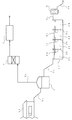
- 1 is a schematic diagram of an organic waste treatment system according to a first embodiment of the present invention.
- 1 is a schematic diagram of an organic waste treatment system according to a first embodiment of the present invention. Schematic of the organic waste processing system which concerns on the 2nd Embodiment of this invention. The top view of the 2nd processing tank concerning the present invention. Schematic of the organic waste processing system which concerns on the 3rd Embodiment of this invention.
- FIG. 1 shows that the generation amount of organic waste is small, and the residence time of methane fermentation in the first treatment tank 1 can be longer (longer) than the set value or the set value, and the organic waste is sufficiently treated with methane fermentation.
- the outline of the system of the present invention at the time is shown.
- the livestock manure (organic waste) generated from the barn 11 which is the source of organic waste is discharged into the pipe 5a maintained in an anaerobic state and is in a completely anaerobic state in the first treatment tank 1 ( Methane fermenter). And the biogas produced
- the fermented liquid after fermentation in the first treatment tank 1 is introduced into the second treatment tank 2 partitioned into a serial multi-tank structure through the pipe 5b, and is fermented there.
- an aerobic process is performed in each tank 21, 22, 23, 24 partitioned by the weirs 2d, 2e, 2f from the upstream to the downstream of the second processing tank 2.
- the arrangement state of the pipe 5b may be either an aerobic state or an anaerobic state.
- the amount of livestock manure (organic waste) in the first treatment tank 1 is relatively small, that is, the first When the processing load in one treatment tank 1 is small (usually in summer), the residence time of methane fermentation in the first treatment tank 1 can be longer than the set value or the set value, and livestock manure is sufficiently treated with methane fermentation is there. The reason is that sufficient methane fermentation has already been performed in the first treatment tank, and almost all biogas generated from livestock manure can be recovered.
- each tank 21, 22, 23, 24 of the 2nd processing tank 2 is a tank for carrying out the aerobic process of the fermented liquid processed by the 1st processing tank, Therefore
- the livestock manure itself which is an organic waste is processed. Therefore, it can be designed to be considerably smaller than the first treatment tank. Therefore, it can design at low cost.
- the fermentation liquid flows from the upstream to the downstream of the second treatment tank 2
- the fermentation liquid flows from each tank to the downstream tank through the inflow portions 2a, 2b, and 2c provided in the lower part of each tank.
- the position where the inflow portions 2a, 2b, and 2c are provided is not limited to the lower portion of each tank.
- the fermented liquor that has been aerobically treated in each layer 21, 22, 23, 24 of the second treatment tank 2 is introduced into the denitrification device 3 through the pipe 5c and subjected to nitrogen reduction treatment, and then discharged through the line 3a. Returned to farmland.
- the pipe 5c may be in an aerobic state.
- the pipe 5c is disposed at the upper part of the tank 24 of the second treatment tank, but may be disposed at the lower part.
- the organic waste treated in the present invention includes, for example, green farm waste and wastewater treatment sludge in addition to the livestock manure generated from the barn 11 described above.
- the green agricultural waste includes not only household waste but also industrial waste, such as agricultural / fishery waste and food processing waste.
- the methane fermentation tank of the first treatment tank 1 used in the present invention is preferably composed of a tank in which air is completely shut off in order to maintain the activity by the absolute anaerobic methane fermentation bacteria.
- the shape and operation of the methane fermenter depends on the solids concentration (usually in the range of 3-40% by weight) and the fermentation temperature (usually about 37 ° C for medium temperature fermentation, about 55 ° C for high temperature fermentation, about 60 ° C for ultrahigh temperature fermentation). The conditions will be different.
- a wet type complete mixing type fermenter in the case of a raw material having a high water content (up to a solid concentration of 10% by weight), a wet type complete mixing type fermenter, and in the case of a raw material having a low water content (a solids concentration of 30 to 40% by weight), It is preferable to use a so-called dry type plug flow type (extrusion type) fermenter.
- the pipe 5 a that sends the organic waste generated from the organic waste generation source 10 to the first treatment tank 1 is also air. It is preferable to have a structure that completely blocks. Note that the tank need not be a tank as long as it is completely anaerobic.
- size of the 1st processing tank 1 to be used can be designed in arbitrary magnitude
- the capacity of the first treatment tank is preferably set smaller than the maximum amount of organic waste generated. Preferably it is less than half of the maximum amount of organic waste generated.
- the methane fermentation tank 1 may be provided with heating means for keeping warm as required.
- the residence time of the methane fermentation treatment performed in the first treatment tank 1 is about 20 to 30 days for medium temperature fermentation, about 15 days for high temperature fermentation, and about 10 days for ultra high temperature fermentation.
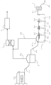
- FIG. 2 shows the system of the present invention when the amount of organic waste generated is large and the residence time of methane fermentation in the first treatment tank 1 is less than the set value, and the methane fermentation treatment of organic waste is insufficient. This is an overview.
- anaerobic treatment is performed in at least the most upstream tank 21 among the tanks 21, 22, 23, 24 of the second treatment tank 2, and other tanks.
- aerobic processing is performed.
- the tank 21 is provided with a cover sheet 21a, which will be described later, to create an anaerobic state.
- the amount of livestock manure (organic waste) in the first treatment tank 1 is large, that is, the first treatment tank 1.
- the processing load in the first treatment tank 1 is large (usually in winter) and a large amount of livestock excreta must be treated, so that the residence time of methane fermentation in the first treatment tank 1 is not more than a set value. That is, since methane fermentation in the 1st processing tank 1 is inadequate, the fermented liquid from the 1st processing tank 1 is anaerobically processed in the tank 21 which is the most upstream of a 2nd processing tank, and a 1st processing tank Biogas that could not be generated can be generated and recovered. Therefore, the tank 21 is provided with a biogas collection pipe 6b for collecting the generated biogas.
- each tank 21, 22, 23, 24 of the 2nd processing tank 2 is a tank for processing the fermented liquid processed by the 1st processing tank, Therefore
- the livestock manure itself which is an organic waste is processed. It can be designed to be considerably smaller than the first treatment tank.
- the tank 21 is completely anaerobic. Therefore, it is desirable that the pipe 5b is also kept in a completely anaerobic state. Furthermore, it is preferable to provide the inflow part 2 a for allowing the fermentation liquid to flow from the tank 21 to the downstream tank 22 below the level of the fermentation liquid in the tank 21. This is because if the inflow portion is provided above the liquid level, air may enter the tank 21 from that portion and an anaerobic state cannot be maintained. In addition, you may perform anaerobic processing in a some tank according to the condition of the methane fermentation with respect to the organic processed material of the 1st processing tank 1. FIG.
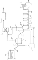
- the first embodiment of the present invention is from the state of FIG. That is, this is an aspect in which the most upstream tank 21 of the second treatment tank 2 can be switched from the aerobic state to the anaerobic state.
- the cover sheet 21a and the control unit 8 are provided, and the uppermost tank 21 of the second treatment tank 2 is automatically changed from the aerobic state to the anaerobic state, or from the anaerobic state to the aerobic state. It is the mode which was made to switch to.
- a flow meter 10 is provided in the middle of the pipe 5a, and the processing amount of livestock manure which is an organic waste discharged from the barn 11 is calculated from the detected value by the control unit 8, and the processing amount is the first processing tank.
- the control unit 8 operates the pump P, which is an air supply means, to operate the second processing tank 2 in the second processing tank 2 when the processing amount is such that the methane fermentation exceeds the set value of the residence time of methane fermentation performed in 1.
- Air is sent into the most upstream tank 21 (covered with the cover sheet 21a) to bring the tank 21 into an aerobic state.
- the control unit 8 opens the valve 9 in order to discharge the supplied air from the tank 21 to the outside by an electric signal.
- the amount of livestock excrement calculated by the control unit 8 from the detection value of the flow meter 10 is equal to or less than the set value of the residence time of methane fermentation performed in the first processing tank 1, and the amount of methane fermentation is insufficient.
- the control unit 8 brings the uppermost tank 21 of the second treatment tank 2 into an anaerobic state by not operating the pump P as the air supply means or by stopping the operation.
- the control unit 8 closes the valve 9 opened by the electric signal.
- the other tanks 22, 23, 24 are kept in an aerobic state.
- the flowmeter 10, the control unit 8, the valve 9, and the pump P automatically change the uppermost tank 21 of the second treatment tank 2 from the aerobic state to the anaerobic state, or from the anaerobic state to the aerobic state. Can be switched automatically.
- FIG. 4 is a plan view of the second treatment tank 2 used in the first embodiment (A), and is a plan view of the second treatment tank 2 used in the second embodiment (B) and A plan view (C) of another embodiment of the two-treatment tank 2 is shown.
- the embodiment of the second treatment tank 2 is not limited to that shown in FIG. 4 as long as the object of the present invention can be achieved.
- the second treatment tank 2 used in each embodiment of the present invention has a structure in which a plurality of tanks 21, 22, 23, 24 divided in a series multi-tank structure are provided in multiple stages.
- the second treatment tank 2 has a concave shape, and weirs 2d, 2e, and 2f are provided inside the concave shape to partition the second treatment tank 2 into a plurality of tanks.
- Inflow portions 2a, 2b, and 2c are provided below the weirs 2d, 2e, and 2f so that the fermented liquid processed in each tank flows from the upstream tank to the downstream tank.
- FIG. 4B in the tank 21, in order to perform anaerobic treatment, the upper part of the tank 21 is covered with a cover case 21a so that air does not enter from the outside, and the inside of the tank 21 is hermetically sealed. The state can be maintained.
- the cover case 21a only needs to maintain anaerobic properties in the tank 21, and examples thereof include a soft resin sheet.
- Part of the cover case is provided with a collection pipe 6b for collecting biogas generated by anaerobic treatment.
- the cover sheet 21a is preferably a lightweight sheet having flexibility. This is because the cover sheet 21a is always pushed up from the liquid level of the fermentation broth by the pressure of the generated gas if it is soft and lightweight, and the generated biogas can be collected efficiently. In addition, it is also possible to use the thing similar to the cover sheet 21a mentioned above for the upper part of the 1st processing tank 1. FIG. If the cover sheet 21a is used for the upper part of the 1st processing tank 1, the manufacturing cost of the 1st processing tank 1 can be restrained low.
- FIG. 4C shows another embodiment of the second treatment tank.
- the weirs 2d, 2e, and 2f are provided so that a gap X is formed from the edge of the second processing tank 2.
- the fermentation liquid itself in the second treatment tank 2 flows in a meandering manner, and the stirring effect of the fermentation liquid in each of the tanks 21, 22, 23, 24 is obtained. It will be obtained.
- the weir 2d is installed without providing the gap X in order to make the tank 21 anaerobic, and the outlet 2a is formed at the lower part of the tank 21.
- the weir 2d is installed without providing the gap X in order to make the tank 21 anaerobic, and the outlet 2a is formed at the lower part of the tank 21.
- FIG. 5 shows a third embodiment of the present invention.
- the structure of the second treatment tank 2 is made independent of the tanks 21, 22, 23, 24, and the tanks 21, 22, 23, 24 are connected in series. is there.
- Each tank 21, 22, 23, 24 is connected in the part of outflow port 2a, 2b, 2c.
- a place where an outlet connecting each tank is provided is appropriately provided in consideration of anaerobic treatment and aerobic treatment.
- the structure of the present Example of the 2nd processing tank 2 is applicable also to a 1st embodiment.
- the treatment of manure discharged from a livestock barn has been taken as an example of the treatment of organic waste, but the present invention is not limited to this treatment, for example, garbage or sewage treatment sludge. It can also be applied to organic waste derived from the like.
- the present invention uses at least the most upstream tank 21 of the second treatment tank 2 as a fermentation time for the methane fermentation treatment of the first treatment tank 1. It is characterized in that it can be switched from an aerobic state to an anaerobic state, or from an anaerobic state to an aerobic state based on the set value.
- the aerobic treatment is performed in the second treatment tank 2 when there is no load on the treatment in the first treatment tank 1, and at least the second treatment tank 2 is loaded when the treatment in the first treatment tank 1 is burdened.
- an aerobic process can be performed in a subsequent tank.
- the load applied to the first treatment tank 1 is distributed in a well-balanced manner.
- the present invention can perform both aerobic treatment and anaerobic treatment on at least the most upstream tank 21 of the second treatment tank 2 according to the state of the methane fermentation treatment of the first treatment tank 1.
- the 2nd processing tank 2 is comprised as a structure which can be switched in this way.
- the present invention has an effect of distributing the load applied to the first treatment tank 1 in a well-balanced manner, and therefore it is not necessary to design the first treatment tank 1 in accordance with the maximum amount of organic waste.
- the first treatment tank 1 is not required to be a large treatment tank at a high cost, and the first treatment tank 1 is designed to be small to reduce costs and to secure a large amount of biogas generation. is doing.
Landscapes
- Life Sciences & Earth Sciences (AREA)
- Chemical & Material Sciences (AREA)
- Engineering & Computer Science (AREA)
- Health & Medical Sciences (AREA)
- Organic Chemistry (AREA)
- Biochemistry (AREA)
- General Chemical & Material Sciences (AREA)
- Molecular Biology (AREA)
- Microbiology (AREA)
- Chemical Kinetics & Catalysis (AREA)
- Biotechnology (AREA)
- Wood Science & Technology (AREA)
- Environmental & Geological Engineering (AREA)
- Zoology (AREA)
- Bioinformatics & Cheminformatics (AREA)
- Genetics & Genomics (AREA)
- Sustainable Development (AREA)
- Oil, Petroleum & Natural Gas (AREA)
- Biomedical Technology (AREA)
- General Engineering & Computer Science (AREA)
- General Health & Medical Sciences (AREA)
- Biodiversity & Conservation Biology (AREA)
- Water Supply & Treatment (AREA)
- Hydrology & Water Resources (AREA)
- Soil Sciences (AREA)
- Clinical Laboratory Science (AREA)
- Processing Of Solid Wastes (AREA)
- Treatment Of Sludge (AREA)
Abstract
有機性廃棄物の発生量が変動するために生じる有機性廃棄物処理の負荷を分散させ、有機性廃棄物処理を低コストで効率よく行えることができる有機性廃棄物処理システムの提供を課題とする。そのために、第1処理槽1のメタン発酵処理の発酵時間の設定値に基づいて、第2処理槽2の少なくとも最上流の槽21を、好気性状態から嫌気性状態へまたは嫌気性状態から好気性状態へ切り替えられるように構成することによって、第1処理槽1にかかる有機性廃棄物処理の負荷変動をバランスよく分散させ、有機性廃棄物の処理量の最大量にあわせて第1処理槽1を設計する必要がないようにして、低コストの有機性廃棄物処理システムを提供する。
Description
本発明は、有機性廃棄物の処理において、有機性廃棄物の発生量が変動するために生じる有機性廃棄物処理の負荷を分散させるための有機性廃棄物処理システムに関するものである。
従来より、家畜糞尿、生ごみ、下水処理汚泥等の有機性廃棄物をメタン発酵処理(嫌気性処理)し、発酵処理によって発生するメタンガスを回収して発電や熱源として利用する技術が知られている(特許文献1)。
特許文献1の図1では、有機性廃棄物をメタン発酵槽でメタン菌によってメタン発酵処理し、発酵処理によって発生したメタンガスを脱硫塔で硫化水素などを除去することによって精製バイオガスとし、回収して熱源等として利用する技術が開示されている。更に、メタン発酵処理によって生じたメタン発酵槽中の発酵液を調整槽に移し、アンモニアが放散され易い状態にするためpH調整した後、好気性処理を行うためエアレーションタンクに移して空気を導入し、エアレーションにより生成する放散アンモニアを含む空気をアンモニアトラップ処理して、アンモニア溶液として回収する技術が開示されている。
また、アンモニア放散後のエアレーションタンク内の発酵残渣を、固液分離機に導入し、液分は水処理設備で浄化した後に放流し、固形分は堆肥設備で肥料化して農地還元する技術も開示されている。
また、アンモニア放散後のエアレーションタンク内の発酵残渣を、固液分離機に導入し、液分は水処理設備で浄化した後に放流し、固形分は堆肥設備で肥料化して農地還元する技術も開示されている。
上記技術では、有機性廃棄物から高収率で精製バイオガスを得るために、メタン発酵槽での滞留時間を充分にとって有機性廃棄物をメタン発酵処理している。
しかし、従来より、実際に有機性廃棄物を処理する際には以下の様な欠点が生じていた。
例えば、畜舎から出る糞尿由来の有機性廃棄物を処理する場合、夏場は家畜を放牧する時間が長いため家畜が畜舎にいる時間が短くなるので、家畜糞尿由来の有機性廃棄物の量はそれ程多くないが、逆に、冬場は家畜を放牧する時間が短いため家畜が畜舎にいる時間が長くなるので、家畜糞尿由来の有機性廃棄物の量が多くなる。
そして、メタン発酵槽は、家畜糞尿由来の有機性廃棄物の処理量が多くなる冬場であっても滞留時間を充分にとってじっくりとメタン発酵させるようにするため、冬場に発生する家畜糞尿由来の有機性廃棄物の量に応じて設計される。つまり、家畜糞尿由来の有機性廃棄物の発生量が最大になる場合に合わせてメタン発酵槽が設計されていた。よって設備が大型化する傾向にあった。
ところが、夏場になると発生する家畜糞尿由来の有機性廃棄物の量が減少するため、冬場に発生する家畜糞尿由来の有機性廃棄物の量に合わせて設計されたメタン発酵槽では、処理する有機性廃棄物の量が少なくなり運転を止めるような場合が生じ(システムの稼動率が下がる)、有機性廃棄物処理を行う上で効率も悪く、コスト的にも割りに合わない状況が生じていた。
逆に、夏場に発生する家畜糞尿由来の有機性廃棄物の量に応じてメタン発酵槽を設計すると、メタン発酵槽は小さく設計できるが、冬場に発生する家畜糞尿由来の有機性廃棄物の量をすべて処理するには、設計したメタン発酵槽の規模では充分な滞留時間がとれず、精製バイオガスの収率が落ちてしまうという欠点があった。
つまり、冬場では家畜糞尿由来の有機性廃棄物の発生量が多くなるのでメタン発酵槽にかかる負荷が大きくなり、逆に、夏場では家畜糞尿由来の有機性廃棄物の発生量が少なくなるのでメタン発酵槽にかかる負荷が小さくなる。
なお、家畜糞尿由来の有機性廃棄物に限らず、生ごみや下水処理汚泥等由来の有機性廃棄物もまた家畜糞尿由来の有機性廃棄物ほど季節との関係はないものの、発生量に変動があるため、その処理については上記家畜糞尿由来の有機性廃棄物と同様の問題点を抱えていた。
本発明はこのような事情に鑑みなされたもので、有機性廃棄物の発生量が変動するために生じる有機性廃棄物処理の負荷を分散させるための有機性廃棄物処理システムを提供するものである。
上記目的を達成するために本発明に係る有機性廃棄物処理システムの第1の態様は、有機性廃棄物を発酵処理する有機性廃棄物処理システムであって、有機性廃棄物を嫌気性発酵させる第1処理槽と、前記第1処理槽からの発酵液を微生物処理する第2処理槽と、を備え、前記第2処理槽は直列に接続された複数の槽からなり、少なくとも最上流の槽は好気性処理条件と嫌気性処理条件の双方に切り替え可能に構成されていることを特徴とする。
本態様によれば、第1処理槽の容量を有機性廃棄物の発生量の最大量より小さく設定することができ、設備の大型化を防止できる。
そして、第2処理槽の少なくとも最上流の槽は、好気性処理条件と嫌気性処理条件の双方に切り替えが可能であるように構成されているので、有機性廃棄物の第1処理槽でのメタン発酵が十分になされていれば(有機性廃棄物の発生量が少ない場合)、第1処理槽からの発酵液を第2処理槽では好気性処理を行う。一方、有機性廃棄物の第1処理槽でのメタン発酵が不十分であれば(有機性廃棄物の発生量が多い場合)、第1処理槽からの発酵液を第2処理槽の少なくとも最上流の槽で嫌気性処理を行うことによって、第1処理槽で発酵が不十分だったために生成しきれなかったバイオガスを生成させ回収することが出来る効果を有する。さらに、第2処理槽の最上流の槽で嫌気性処理が行われた発酵液は、直列に複数接続されている下流の各槽で好気性処理を行うことが可能である。
すなわち、有機性廃棄物の発生量が変動することによる負荷がバランスよく分散されるようになっている。
そして、第2処理槽の少なくとも最上流の槽は、好気性処理条件と嫌気性処理条件の双方に切り替えが可能であるように構成されているので、有機性廃棄物の第1処理槽でのメタン発酵が十分になされていれば(有機性廃棄物の発生量が少ない場合)、第1処理槽からの発酵液を第2処理槽では好気性処理を行う。一方、有機性廃棄物の第1処理槽でのメタン発酵が不十分であれば(有機性廃棄物の発生量が多い場合)、第1処理槽からの発酵液を第2処理槽の少なくとも最上流の槽で嫌気性処理を行うことによって、第1処理槽で発酵が不十分だったために生成しきれなかったバイオガスを生成させ回収することが出来る効果を有する。さらに、第2処理槽の最上流の槽で嫌気性処理が行われた発酵液は、直列に複数接続されている下流の各槽で好気性処理を行うことが可能である。
すなわち、有機性廃棄物の発生量が変動することによる負荷がバランスよく分散されるようになっている。
本発明に係る有機性廃棄物処理システムの第2の態様は、第1の態様における有機性廃棄物処理システムにおいて、前記有機性廃棄物の前記第1処理槽での滞留時間が前記有機性廃棄物の発生源における発生量の変動によって設定値以下になるときは、前記第2処理槽の少なくとも最上流の槽で嫌気性処理を行い、他の槽では好気性処理を行う制御を実行する制御部を備えていることを特徴とする。
本態様によれば、有機性廃棄物の発生源における発生量の変動によって、第1処理槽での滞留時間が設定値以下になる場合には、すなわち第1処理槽において、有機性廃棄物の処理量が多くなり(負荷が大きくなり)メタン発酵が十分でない場合には、第2処理槽の少なくとも最上流の槽で嫌気性処理を行い、他の槽では好気性処理を行うことによって、第1処理槽の有機性廃棄物の処理の負荷を分散できる効果を有する。さらに、第1処理槽の有機性廃棄物の処理の負荷を分散できることから、第1処理槽を小さく設計することができ、低コストで第1処理槽を製造できる。
本発明に係る有機性廃棄物処理システムの第3の態様は、第1の態様または第2の態様における有機性廃物処理システムにおいて、前記第1処理槽で発生したバイオガスを利用するバイオガス利用装置を備え、第2処理槽において嫌気性処理して生成したバイオガスを前記バイオガス利用装置に送るように構成されていることを特徴とする。
本態様によれば、第1処理槽でメタン発酵によって生成したバイオガスを回収して利用すると共に、第1処理槽でメタン発酵が不十分なために、すなわち滞留時間が設定値以下で処理されたためにバイオガスが十分に生成しきれなかった場合であっても、第2処理槽において嫌気性処理することによってバイオガスを生成させる。そして、そのバイオガスをバイオガス利用装置に送ることによって、より多くのバイオガスを利用することができる効果を有している。
本発明に係る有機性廃棄物処理システムの第4の態様は、第1の態様から第3の態様のいずれか1つの態様における有機性廃物処理システムにおいて、前記第2処理槽で嫌気性と好気性が切り替え可能に構成された槽は、該槽内から隣接する槽内への処理液の流入部が液面下に設けられていることを特徴とする。
本態様によれば、第2処理槽の嫌気性と好気性が切り替え可能に構成された槽から隣接する他の槽内への発酵液の流入部を液面下に設けることにより、該槽の嫌気性を容易に保つことが可能となる。
本発明に係る有機性廃棄物処理システムの第5の態様は、第1の態様から第3の態様のいずれか1つの態様における有機性廃物処理システムにおいて、前記第2処理槽は、単一の槽を堰で区画して、直列多槽構造としたことを特徴とする。
本態様によれば、第2処理槽の単一の槽を、堰で区画して直列多槽構造とすることにより、区画された槽でそれぞれ別々の処理(好気性処理又は嫌気性処理)を行うことが出来るという効果を有する。また、堰を設けるだけで区画された単一の槽を製造できるので、個々に槽を複数個製造するよりも低コストで槽を製造することができる。
本発明に係る有機性廃棄物処理システムの第6の態様は、第1の態様から第3の態様のいずれか1つの態様における有機性廃棄物処理システムにおいて、前記第2処理槽に空気を送り込む送気手段を備えていることを特徴とする。
好気性の槽といっても、上面が開放されているのみでは、槽の上部の部分は好気性となるが下部の部分は嫌気性となる傾向がある。すなわち、1つの槽の中で好気性と嫌気性の部分が存在し槽全体が好気性にはなっていない。そこで、本態様によれば、送気手段を使って空気を槽内に送り込むことで槽全体を好気性にすることが出来る。また、送気手段による送気を止めることによって嫌気性の槽から好気性の槽に短時間で容易に切り替えることが出来る。
本発明によれば、有機性廃棄物の発生量が変動するために生じる有機性廃棄物処理の負荷を分散させ、低コストで効率よく有機性廃棄物を処理できる有機性廃棄物処理システムの実現が可能となる。さらに、バイオガスの生成量を多く確保することも可能となる。
以下、図を参照しながら、本発明に係る有機性廃棄物処理システムの実施形態について説明する。なお、本発明は以下の実施形態に限定されるものではない。
[第1の実施態様]
本発明の有機性廃棄物処理システムの第1の実施態様を図1及び図2を参照にしながら説明する。
図1は、有機性廃棄物の発生量が少なく第1処理槽1でのメタン発酵の滞留時間が設定値あるいは設定値より多く(長く)取れ、有機性廃棄物が十分にメタン発酵処理される際における本発明のシステムの概要をあらわしたものである。
本発明の有機性廃棄物処理システムの第1の実施態様を図1及び図2を参照にしながら説明する。
図1は、有機性廃棄物の発生量が少なく第1処理槽1でのメタン発酵の滞留時間が設定値あるいは設定値より多く(長く)取れ、有機性廃棄物が十分にメタン発酵処理される際における本発明のシステムの概要をあらわしたものである。
有機性廃棄物の発生源である畜舎11から発生した家畜の糞尿(有機性廃棄物)は、嫌気性の状態が保たれた配管5aに排出され、完全嫌気状態にある第1処理槽1(メタン発酵槽)に導入される。
そして、第1処理槽1でメタン発酵によって生成されるバイオガスは、バイオガス収集管6aで収集され、その後脱硫装置4で硫化水素等が除去される。そして、精製バイオガスとしてバイオガス利用装置7に送られ、電力、燃料等に利用される。
そして、第1処理槽1でメタン発酵によって生成されるバイオガスは、バイオガス収集管6aで収集され、その後脱硫装置4で硫化水素等が除去される。そして、精製バイオガスとしてバイオガス利用装置7に送られ、電力、燃料等に利用される。
一方、第1処理槽1内の発酵後の発酵液は、配管5bを通じて直列多槽構造に区画された第2処理槽2に導入され、そこで発酵処理される。ここで、本実施態様の場合は、第2処理槽2の上流から下流において堰2d、2e、2fで仕切られた各槽21、22、23、24において好気性処理が行われる。なお、配管5bの配設状態は好気性の状態でも嫌気性の状態でもどちらであっても良い。
第2処理槽2の各層21、22、23、24において好気性処理のみを行う場合は、第1処理槽1における家畜糞尿(有機性廃棄物)の処理量が比較的少ない場合、すなわち、第1処理槽1における処理の負荷が小さく(通常は夏場)、第1処理槽1でのメタン発酵の滞留時間が設定値あるいは設定値より多く取れ、家畜糞尿が十分にメタン発酵処理されるときである。その理由は、第1処理槽で既に十分なメタン発酵が行われ、家畜糞尿から発生するバイオガスを殆ど回収できるためである。
なお、第2処理槽2の各槽21、22、23、24は、第1処理槽で処理された発酵液を好気性処理するための槽なので、有機性廃棄物である家畜糞尿自体を処理する第1処理槽に較べてかなり小さく設計することが可能である。したがって低コストで設計することができる。
第2処理槽2の上流から下流に発酵液が流れる際には、各槽の下部に設けられた流入部2a、2b、2cを通じて、各槽から発酵液が下流の槽へ流れる構造となっている。なお、本実施態様では、流入部2a、2b、2cを設ける位置は各槽の下部に限られない。
第2処理槽2の各層21、22、23、24において好気性処理された発酵液は、配管5cを通じて脱窒装置3に導入され、窒素低減処理を行った後、ライン3aを介して放流あるいは農地へ還元される。この際、配管5cは好気状態で構わない。また、本実施例では配管5cは第2処理槽の槽24の上部に配設されているが下部に配設しても良い。
本発明で処理される有機性廃棄物は、上述した畜舎11から発生する家畜の糞尿以外に、例えば、緑農廃棄物や排水処理汚泥などが挙げられる。ここで緑農廃棄物としては、家庭の生ごみのほか、産業廃棄物生ごみとして農水産業廃棄物、食品加工廃棄物等が含まれる。
また、本発明で使用される第1処理槽1のメタン発酵槽は、絶対嫌気性のメタン発酵菌による活動を維持するために、空気を完全に遮断したタンクにより構成されることが望ましい。メタン発酵槽は固形物濃度(通常3~40重量%の範囲)と発酵温度(通常、中温発酵では約37℃、高温発酵では約55℃、超高温発酵では約60℃)によって、形状や運転条件が異なってくる。例えば、高含水率になった原料(固形物濃度10重量%まで)の場合は湿式型の完全混合方式の発酵槽、低含水率の原料(固形物濃度30~40重量%)の場合は、いわゆる乾式型のプラグフロー式(押出し式)の発酵槽を用いることが好ましい。なお、第1処理槽1のメタン発酵槽内のメタン発酵菌による活動を維持するために、有機性廃棄物発生源10から発生する有機性廃棄物を第1処理槽1へ送る配管5aも空気を完全に遮断する構造とするのが好ましい。なお、完全嫌気の状態が保てればタンクでなくとも良い。
本発明では、使用する第1処理槽1の大きさは、処理する有機性廃棄物の処理量に応じて任意の大きさに設計することができるが、本発明の目的を達成するためには、第1処理槽の容量を有機性廃棄物の発生量の最大量より小さく設定するのがよい。好ましくは有機性廃棄物の発生量の最大量の半分以下であることが望ましい。また、本実施態様では、第1処理槽を1台設置しているが、規模に応じて複数台設置しても良い。更に、メタン発酵槽1には必要に応じて保温のための加熱手段を設けておいてもよい。
第1処理槽1内で行われるメタン発酵処理の滞留時間は、中温発酵では20~30日間程度、高温発酵では15日間程度、超高温発酵では10日間程度である。
第1処理槽1内で行われるメタン発酵処理の滞留時間は、中温発酵では20~30日間程度、高温発酵では15日間程度、超高温発酵では10日間程度である。
図2は、有機性廃棄物の発生量が多く第1処理槽1でのメタン発酵の滞留時間が設定値以下となり、有機性廃棄物のメタン発酵処理が不十分な場合における本発明のシステムの概要をあらわしたものである。
第1処理槽1でのメタン発酵が不十分な場合では、第2処理槽2の各槽21、22、23、24のうちで少なくとも最上流の槽21において嫌気性処理を行い、他の槽22、23、24では好気性処理を行うようになっている。槽21に後述するカバーシート21aが設けられて嫌気性状態を作るようになっている。
第2処理槽2の最上流の槽21において嫌気性処理を必要とする場合は、第1処理槽1における家畜糞尿(有機性廃棄物)の処理量が多い場合、すなわち、第1処理槽1における処理の負荷が大きく(通常は冬場)、多量の家畜糞尿を処理しなければならないため、第1処理槽1でのメタン発酵の滞留時間が設定値以下の場合である。
つまり、第1処理槽1でのメタン発酵が不十分であるため、第2処理槽の最上流である槽21で第1処理槽1からの発酵液を嫌気性処理し、第1処理槽で発生しきれなかったバイオガスを発生させ回収できるようになっている。よって、槽21には発生するバイオガスを収集するためのバイオガス収集管6bが配設されている。
つまり、第1処理槽1でのメタン発酵が不十分であるため、第2処理槽の最上流である槽21で第1処理槽1からの発酵液を嫌気性処理し、第1処理槽で発生しきれなかったバイオガスを発生させ回収できるようになっている。よって、槽21には発生するバイオガスを収集するためのバイオガス収集管6bが配設されている。
ここで、第2処理槽2の各槽21、22、23、24は、第1処理槽で処理された発酵液を処理するための槽なので、有機性廃棄物である家畜糞尿自体を処理する第1処理槽に較べてかなり小さく設計することが可能である。
従って、有機性廃棄物である家畜糞尿を多量に処理するために第1処理槽を増設するよりは、第2処理槽2に槽を直列的に複数設けた方がコストを低く抑えることができることとなる。
なお、第2処理槽2の槽は、槽22、23、24とあるので好気性処理を行うには容量的に十分であり、最上流である槽21を嫌気性処理槽として使用しても、好気性処理を妨げるほどのことにはならない。
なお、第2処理槽2の槽は、槽22、23、24とあるので好気性処理を行うには容量的に十分であり、最上流である槽21を嫌気性処理槽として使用しても、好気性処理を妨げるほどのことにはならない。
また、槽21は完全嫌気性であることが好ましく、そのため配管5bも完全嫌気性の状態を保っていることが望ましい。更に、槽21から下流の槽22へ発酵液を流入させるための流入部2aは槽21の発酵液の液面下に設けるのが好ましい。液面より上部に流入部を設けることとすると、その部分から空気が槽21に入り込む可能性があり嫌気性の状態を保てないからである。
なお、嫌気性処理は、第1処理槽1の有機性処理物に対するメタン発酵の状況に応じて、複数の槽で行っても良い。
なお、嫌気性処理は、第1処理槽1の有機性処理物に対するメタン発酵の状況に応じて、複数の槽で行っても良い。
本発明の第1の実施態様は、有機性廃棄物の発生量に起因して、第1処理槽1における有機性廃棄物のメタン発酵の状況に応じ、図1の状態から図2の状態、すなわち第2処理槽2の最上流の槽21を好気性の状態から嫌気性の状態に切り替えることが出来る態様である。
[第2の実施態様]
次に、本発明の有機性廃棄物処理システムの第2の実施態様を、図3を参照にしながら説明する。なお、第1の実施態様、第2の実施態様と同一の部分については説明を省略する。
次に、本発明の有機性廃棄物処理システムの第2の実施態様を、図3を参照にしながら説明する。なお、第1の実施態様、第2の実施態様と同一の部分については説明を省略する。
第2の実施態様は、カバーシート21a及び制御部8が設けられ、第2処理槽2の最上流の槽21を好気性状態から嫌気性状態へ、あるいは嫌気性状態から好気性状態へ自動的に切り替えられるようにした態様である。
配管5aの途中に流量計10を設け、制御部8によってその検出値から畜舎11から排出される有機性廃棄物である家畜糞尿の処理量を計算し、さらにその処理量が、第1処理槽1で行われるメタン発酵の滞留時間の設定値を超えて完全にメタン発酵される処理量である場合には、制御部8は送気手段であるポンプPを稼動させて第2処理槽2の最上流の槽21(カバーシート21aで覆われている)に空気を送り込み、槽21を好気性状態にする。
この際、制御部8は電気信号により、送り込んだ空気を槽21から外部へ排出させるためバルブ9を開放する。
この際、制御部8は電気信号により、送り込んだ空気を槽21から外部へ排出させるためバルブ9を開放する。
一方、流量計10の検出値から制御部8によって計算された家畜糞尿の処理量が、第1処理槽1で行われるメタン発酵の滞留時間の設定値以下でメタン発酵が不十分となる処理量である場合には、制御部8は送気手段であるポンプPを稼動させずに、あるいは稼動を停止することにより第2処理槽2の最上流の槽21を嫌気性状態にする。この際、槽21を好気性状態から嫌気性状態にする場合は、制御部8は電気信号により開放していたバルブ9を閉じる。他の槽22,23,24は好気性状態に保たれる。
上記のように、流量計10、制御部8、バルブ9およびポンプPにより第2処理槽2の最上流の槽21を好気性状態から嫌気性状態へ、あるいは嫌気性状態から好気性状態へ自動的に切り替えられるようになっている。
次に、第2処理槽2の構成について図4を参照にしながら説明する。
図4には、第1の実施態様に使用する第2処理槽2の平面図である(A)、第2の実施態様に使用する第2処理槽2の平面図である(B)および第2処理槽2の他の実施態様の平面図(C)が示されている。
なお、第2処理槽2の実施態様は本発明の目的が達成できる態様であれば、図4に示されたものに限定されるものではない。
図4には、第1の実施態様に使用する第2処理槽2の平面図である(A)、第2の実施態様に使用する第2処理槽2の平面図である(B)および第2処理槽2の他の実施態様の平面図(C)が示されている。
なお、第2処理槽2の実施態様は本発明の目的が達成できる態様であれば、図4に示されたものに限定されるものではない。
本発明の各実施態様で使用する第2処理槽2は、直列多槽構造に区画された複数の槽21、22、23,24が多段的に設けられている構造を有している。
第2処理槽2は凹形状をしており、その凹形状の内部に堰2d、2e、2fを設けて、第2処理槽2内を複数の槽に区画している。堰2d、2e、2fの下部には流入部2a、2b、2cが設けられており、各槽で処理された発酵液が上流の槽から下流の槽へ流れるようになっている。
第2処理槽2は凹形状をしており、その凹形状の内部に堰2d、2e、2fを設けて、第2処理槽2内を複数の槽に区画している。堰2d、2e、2fの下部には流入部2a、2b、2cが設けられており、各槽で処理された発酵液が上流の槽から下流の槽へ流れるようになっている。
図4(A)において、流入口2a、2b、2cは、槽21、22、23、24の上部が開放されている好気性状態にあるため、堰2d、2e、2fの発酵液の液面より上部に設けてもよい。
一方、図4(B)において、槽21では、嫌気性処理を行うために槽21の上部をカバーケース21aで覆い外部から空気が入らないようにし、槽21の内部を密閉状態にして嫌気性状態を保てるようになっている。
カバーケース21aは、槽21内の嫌気性を保てるものであれば良く、例えば軟質樹脂シートが挙げられる。カバーケースの一部には嫌気性処理によって発生するバイオガスを収集するための収集管6bが設けられている。
カバーケース21aは、槽21内の嫌気性を保てるものであれば良く、例えば軟質樹脂シートが挙げられる。カバーケースの一部には嫌気性処理によって発生するバイオガスを収集するための収集管6bが設けられている。
ここで、カバーシート21aは柔軟性を有する軽量のものが好ましい。軟質で軽量であれば発生するガスの圧力によって該カバーシート21aが常に発酵液の液面より押し上げられるため、発生するバイオガスを効率よく収集できからである。
なお、上述したカバーシート21aと同様のものを第1処理槽1の上部に使用することも可能である。第1処理槽1の上部にカバーシート21aを使用すれば、第1処理槽1の製造コストを低く抑えることができる。
なお、上述したカバーシート21aと同様のものを第1処理槽1の上部に使用することも可能である。第1処理槽1の上部にカバーシート21aを使用すれば、第1処理槽1の製造コストを低く抑えることができる。
図4(C)には、第2処理槽の他の実施態様が記載されている。
本態様では、堰2d、2e、2fを、第2処理槽2の縁部から隙間Xができるように設けた態様である。図4(C)のような構造にすることによって、第2処理槽2中の発酵液自体が蛇行して流れるようになり、各槽21、22、23、24での発酵液の撹拌効果が得られるようになる。
なお、第2処理槽2の最上流の槽21で嫌気性処理を行うときは、堰2dは槽21を嫌気状態にするため隙間Xを設けずに設置し、槽21の下部に流出口2aを設けるようにする。
本態様では、堰2d、2e、2fを、第2処理槽2の縁部から隙間Xができるように設けた態様である。図4(C)のような構造にすることによって、第2処理槽2中の発酵液自体が蛇行して流れるようになり、各槽21、22、23、24での発酵液の撹拌効果が得られるようになる。
なお、第2処理槽2の最上流の槽21で嫌気性処理を行うときは、堰2dは槽21を嫌気状態にするため隙間Xを設けずに設置し、槽21の下部に流出口2aを設けるようにする。
図5には、本発明の第3の実施形態が示されている。
本実施形態では、第2の実施態様において第2処理槽2の構造を各槽21、22、23、24と独立にして、各槽21、22、23、24同士を直列に接続した態様である。各槽21、22、23、24は流出口2a、2b、2cの部分で接続されている。また、各槽を接続する流出口を設ける場所については、嫌気性処理、好気性処理を考慮して適宜設けるようにする。なお、第2処理槽2の本実施例の構造は、第1の実施態様にも適用できる。
本実施形態では、第2の実施態様において第2処理槽2の構造を各槽21、22、23、24と独立にして、各槽21、22、23、24同士を直列に接続した態様である。各槽21、22、23、24は流出口2a、2b、2cの部分で接続されている。また、各槽を接続する流出口を設ける場所については、嫌気性処理、好気性処理を考慮して適宜設けるようにする。なお、第2処理槽2の本実施例の構造は、第1の実施態様にも適用できる。
本発明の実施態様では、有機性廃棄物の処理として畜舎から排出される糞尿の処理を例に挙げたが、本発明は当該処理に限定されるものではなく、例えば、生ごみや下水処理汚泥等由来の有機性廃棄物にも適用することができる。
第1の実施態様から第3の実施態様に基づいて本発明を説明したが、本発明は第2処理槽2の少なくとも最上流の槽21を、第1処理槽1のメタン発酵処理の発酵時間の設定値に基づいて、好気性状態から嫌気性状態へ、または嫌気性状態から好気性状態へ切り替えられるところに特徴がある。
つまり、第1処理槽1の処理に負荷がかからない場合には第2処理槽2で好気性処理を行い、第1処理槽1の処理に負荷がかかる場合には第2処理槽2の少なくとも最上流の槽21で嫌気性処理を行った後、後段の槽で好気性処理を行うことができるようになっている。言い換えると、第1処理槽1にかかる負荷をバランスよく分散するようになっている。
そして、そのために本発明は、第2処理槽2の少なくとも最上流の槽21を、第1処理槽1のメタン発酵処理の状況に応じて、好気性処理と嫌気性処理の双方の処理ができるように切り替え可能な構造として、第2処理槽2を構成している。
そして、そのために本発明は、第2処理槽2の少なくとも最上流の槽21を、第1処理槽1のメタン発酵処理の状況に応じて、好気性処理と嫌気性処理の双方の処理ができるように切り替え可能な構造として、第2処理槽2を構成している。
以上、本発明は、第1処理槽1にかかる負荷をバランスよく分散する効果を有するため、有機性廃棄物の処理量の最大量にあわせて第1処理槽1を設計する必要がなく、つまり、第1処理槽1をコストをかけて大きい処理槽とする必要が無く、第1処理槽1を小さく設計しコストを抑えると共に、バイオガスの生成量も多く確保することができるという効果を有している。
1 第1処理槽、 2 第2処理槽、 2a、2b、2c 流入部、 2d、2e、2f 堰、 3 脱窒装置、 3a ライン、 4 脱硫装置、 5a、5b、5c 配管、 6a、6b バイオガス収集管、 7 バイオガス利用装置、 8 制御部、 9 バルブ、 10 流量計、 11 畜舎、 21、22、23、24 槽
Claims (6)
- 有機性廃棄物を発酵処理する有機性廃棄物処理システムであって、
有機性廃棄物を嫌気性発酵させる第1処理槽と、
前記第1処理槽からの発酵液を微生物処理する第2処理槽と、を備え、
前記第2処理槽は、直列に接続された複数の槽からなり、少なくとも最上流の槽は好気性処理条件と嫌気性処理条件の双方に切り替え可能に構成されていることを特徴とする有機性廃棄物処理システム。 - 請求項1に記載の有機性廃棄物処理システムにおいて、前記有機性廃棄物の前記第1処理槽での滞留時間が前記有機性廃棄物の発生源における発生量の変動によって設定値以下になるときは、前記第2処理槽の少なくとも最上流の槽で嫌気性処理を行い、他の槽では好気性処理を行う制御を実行する制御部を備えていることを特徴とする有機性廃棄物処理システム。
- 請求項1または2のいずれか1項に記載の有機性廃物処理システムにおいて、前記第1処理槽で発生したバイオガスを利用するバイオガス利用装置を備え、第2処理槽において嫌気性処理して生成したバイオガスを前記バイオガス利用装置に送るように構成されていることを特徴とする有機性廃棄物処理システム。
- 請求項1から3のいずれか1項に記載の有機性廃物処理システムにおいて、前記第2処理槽で嫌気性と好気性が切り替え可能に構成された槽は、該槽内から隣接する槽内への処理液の流入部が液面下に設けられていることを特徴とする有機性廃棄物処理システム。
- 請求項1から3のいずれか1項に記載の有機性廃物処理システムにおいて、前記第2処理槽は、単一の槽を堰で区画して、直列多槽構造としたことを特徴とする有機性廃棄物処理システム。
- 請求項1から3のいずれか1項の有機性廃棄物処理システムにおいて、前記第2処理槽に空気を送り込む送気手段を備えていることを特徴とする有機性廃棄物処理システム。
Priority Applications (1)
| Application Number | Priority Date | Filing Date | Title |
|---|---|---|---|
| JP2010536634A JPWO2010052804A1 (ja) | 2008-11-07 | 2009-03-31 | 有機性廃棄物処理システム |
Applications Claiming Priority (2)
| Application Number | Priority Date | Filing Date | Title |
|---|---|---|---|
| JP2008-286628 | 2008-11-07 | ||
| JP2008286628 | 2008-11-07 |
Publications (1)
| Publication Number | Publication Date |
|---|---|
| WO2010052804A1 true WO2010052804A1 (ja) | 2010-05-14 |
Family
ID=42152617
Family Applications (1)
| Application Number | Title | Priority Date | Filing Date |
|---|---|---|---|
| PCT/JP2009/001509 Ceased WO2010052804A1 (ja) | 2008-11-07 | 2009-03-31 | 有機性廃棄物処理システム |
Country Status (2)
| Country | Link |
|---|---|
| JP (1) | JPWO2010052804A1 (ja) |
| WO (1) | WO2010052804A1 (ja) |
Cited By (4)
| Publication number | Priority date | Publication date | Assignee | Title |
|---|---|---|---|---|
| JP2012035222A (ja) * | 2010-08-10 | 2012-02-23 | Toshiba Corp | メタン発酵槽及び天幕用カバーシートの施工方法 |
| JP2012236115A (ja) * | 2011-05-09 | 2012-12-06 | Eco Power Corp | メタン発酵システム |
| CN104226671A (zh) * | 2013-06-11 | 2014-12-24 | 远东生物科技股份有限公司 | 生物废弃物绿色处理系统及方法 |
| CN107253804A (zh) * | 2017-07-28 | 2017-10-17 | 武汉益锦祥生物环保有限公司 | 一种畜禽养殖污水处理及综合利用方法 |
Citations (2)
| Publication number | Priority date | Publication date | Assignee | Title |
|---|---|---|---|---|
| JP2002307098A (ja) * | 2001-04-13 | 2002-10-22 | Mitsubishi Heavy Ind Ltd | 有機性汚泥の嫌気性消化方法及び嫌気性消化装置 |
| JP2003190923A (ja) * | 2001-12-28 | 2003-07-08 | Taikisha Ltd | 有機物処理方法、及び、有機物処理装置 |
-
2009
- 2009-03-31 JP JP2010536634A patent/JPWO2010052804A1/ja active Pending
- 2009-03-31 WO PCT/JP2009/001509 patent/WO2010052804A1/ja not_active Ceased
Patent Citations (2)
| Publication number | Priority date | Publication date | Assignee | Title |
|---|---|---|---|---|
| JP2002307098A (ja) * | 2001-04-13 | 2002-10-22 | Mitsubishi Heavy Ind Ltd | 有機性汚泥の嫌気性消化方法及び嫌気性消化装置 |
| JP2003190923A (ja) * | 2001-12-28 | 2003-07-08 | Taikisha Ltd | 有機物処理方法、及び、有機物処理装置 |
Cited By (5)
| Publication number | Priority date | Publication date | Assignee | Title |
|---|---|---|---|---|
| JP2012035222A (ja) * | 2010-08-10 | 2012-02-23 | Toshiba Corp | メタン発酵槽及び天幕用カバーシートの施工方法 |
| JP2012236115A (ja) * | 2011-05-09 | 2012-12-06 | Eco Power Corp | メタン発酵システム |
| CN104226671A (zh) * | 2013-06-11 | 2014-12-24 | 远东生物科技股份有限公司 | 生物废弃物绿色处理系统及方法 |
| CN107253804A (zh) * | 2017-07-28 | 2017-10-17 | 武汉益锦祥生物环保有限公司 | 一种畜禽养殖污水处理及综合利用方法 |
| CN107253804B (zh) * | 2017-07-28 | 2019-10-22 | 武汉益锦祥生物环保有限公司 | 一种畜禽养殖污水处理及综合利用方法 |
Also Published As
| Publication number | Publication date |
|---|---|
| JPWO2010052804A1 (ja) | 2012-03-29 |
Similar Documents
| Publication | Publication Date | Title |
|---|---|---|
| AU2002348041B2 (en) | Fixed-film anaerobic digestion of flushed manure | |
| US8765449B2 (en) | Three stage, multiple phase anaerobic digestion system and method | |
| CN201538737U (zh) | 一种集成化禽畜养殖场粪污生物处理系统 | |
| US20100155313A1 (en) | System and method for thermophilic anaerobic digester process | |
| Ji et al. | Integrated ABR and UASB system for dairy wastewater treatment: Engineering design and practice | |
| CN101698556B (zh) | 一种麦草浆造纸中段废水处理方法及处理设备 | |
| US9409806B2 (en) | System and method for thermophilic anaerobic digester process | |
| Valijanian et al. | Biogas production systems | |
| AU2002348041A1 (en) | Fixed-film anaerobic digestion of flushed manure | |
| CN101434450B (zh) | 沼气生产过程中的厌氧消化处理方法及设备 | |
| KR101439425B1 (ko) | 에너지 절감형 바이오가스 플랜트 | |
| WO2008026221A1 (en) | A self mixing anaerobic digester useful for treatment of solid organic waste | |
| CN201962120U (zh) | 一种高效两相一体化厌氧反应器 | |
| EP3044172B1 (en) | Digestion of organic sludge | |
| WO2010052804A1 (ja) | 有機性廃棄物処理システム | |
| Batubara et al. | Variations of organic loading rate on tofu wastewater degradation using upflow anaerobic sludge blanket reactor by modified Stover-Kincannon model | |
| KR100743373B1 (ko) | 축산분뇨의 혐기발효를 이용한 바이오가스 제조장치 | |
| CN113429076A (zh) | 生活污水的处理系统和处理方法 | |
| Balasundaram et al. | Comparative study of different media in the treatment of sago wastewater using HUASB reactor | |
| CN217336633U (zh) | 一种养殖种植系统 | |
| CN212655649U (zh) | 一种废水处理系统 | |
| CN210103710U (zh) | 一种低碳氮比化工污水的滤池 | |
| CN205710098U (zh) | 污水深度净化系统 | |
| CN205346953U (zh) | 一种一体化两相厌氧反应塔 | |
| CN220183025U (zh) | 一种用于养殖废水处理的生态沟渠 |
Legal Events
| Date | Code | Title | Description |
|---|---|---|---|
| 121 | Ep: the epo has been informed by wipo that ep was designated in this application |
Ref document number: 09824506 Country of ref document: EP Kind code of ref document: A1 |
|
| WWE | Wipo information: entry into national phase |
Ref document number: 2010536634 Country of ref document: JP |
|
| NENP | Non-entry into the national phase |
Ref country code: DE |
|
| 122 | Ep: pct application non-entry in european phase |
Ref document number: 09824506 Country of ref document: EP Kind code of ref document: A1 |