WO2010050701A2 - 대형 디젤엔진 유압식 배기밸브 구동장치에서의 캐비테이션 방지용 배기밸브 감쇄장치 - Google Patents
대형 디젤엔진 유압식 배기밸브 구동장치에서의 캐비테이션 방지용 배기밸브 감쇄장치 Download PDFInfo
- Publication number
- WO2010050701A2 WO2010050701A2 PCT/KR2009/006140 KR2009006140W WO2010050701A2 WO 2010050701 A2 WO2010050701 A2 WO 2010050701A2 KR 2009006140 W KR2009006140 W KR 2009006140W WO 2010050701 A2 WO2010050701 A2 WO 2010050701A2
- Authority
- WO
- WIPO (PCT)
- Prior art keywords
- exhaust valve
- check valve
- valve
- damping
- piston
- Prior art date
- Legal status (The legal status is an assumption and is not a legal conclusion. Google has not performed a legal analysis and makes no representation as to the accuracy of the status listed.)
- Ceased
Links
Images


Classifications
-
- F—MECHANICAL ENGINEERING; LIGHTING; HEATING; WEAPONS; BLASTING
- F01—MACHINES OR ENGINES IN GENERAL; ENGINE PLANTS IN GENERAL; STEAM ENGINES
- F01L—CYCLICALLY OPERATING VALVES FOR MACHINES OR ENGINES
- F01L9/00—Valve-gear or valve arrangements actuated non-mechanically
- F01L9/10—Valve-gear or valve arrangements actuated non-mechanically by fluid means, e.g. hydraulic
-
- F—MECHANICAL ENGINEERING; LIGHTING; HEATING; WEAPONS; BLASTING
- F01—MACHINES OR ENGINES IN GENERAL; ENGINE PLANTS IN GENERAL; STEAM ENGINES
- F01L—CYCLICALLY OPERATING VALVES FOR MACHINES OR ENGINES
- F01L1/00—Valve-gear or valve arrangements, e.g. lift-valve gear
- F01L1/02—Valve drive
- F01L1/04—Valve drive by means of cams, camshafts, cam discs, eccentrics or the like
- F01L1/08—Shape of cams
-
- F—MECHANICAL ENGINEERING; LIGHTING; HEATING; WEAPONS; BLASTING
- F01—MACHINES OR ENGINES IN GENERAL; ENGINE PLANTS IN GENERAL; STEAM ENGINES
- F01L—CYCLICALLY OPERATING VALVES FOR MACHINES OR ENGINES
- F01L2810/00—Arrangements solving specific problems in relation with valve gears
- F01L2810/03—Reducing vibration
-
- F—MECHANICAL ENGINEERING; LIGHTING; HEATING; WEAPONS; BLASTING
- F01—MACHINES OR ENGINES IN GENERAL; ENGINE PLANTS IN GENERAL; STEAM ENGINES
- F01L—CYCLICALLY OPERATING VALVES FOR MACHINES OR ENGINES
- F01L2810/00—Arrangements solving specific problems in relation with valve gears
- F01L2810/04—Reducing noise
Definitions
- the present invention relates to an exhaust valve attenuator for preventing cavitation in a large diesel engine hydraulic exhaust valve driving apparatus. Specifically, the present invention relates to a cavitation phenomenon generated by rapidly expanding a volume inside the attenuation cylinder of the exhaust valve attenuator during the opening of the exhaust valve. The present invention relates to a device for preventing noise, vibration and erosion damage caused by cavitation.
- the exhaust valve is a valve for discharging the exhaust gas of the combustion chamber to the exhaust duct after combustion.
- Hydraulic exhaust valve driving device is a device for driving the exhaust valve by using the hydraulic pressure is simple compared to the mechanically connected driving device, there is a small risk of structural damage and vibration and noise has a small advantage.
- the size of the exhaust valve driving device driven by kinematic driving is considerably larger, and hydraulic exhaust valve driving devices have been applied for a long time.
- Figure 4 is an exemplary view showing the operation and operation of the conventional hydraulic exhaust valve drive, as shown in the exhaust cam 501 is rotated as the lift of the cam lifts the drive piston 502 rises and the drive oil cylinder ( 503, the hydraulic oil is compressed to increase the pressure.
- the pressure of the hydraulic oil compressed by the driving oil cylinder 503 is transferred to the oil cylinder 505 of the exhaust valve part through the hydraulic pipe 504, and this pressure acts on the exhaust valve piston 506 to exhaust the valve 507.
- the exhaust valve 507 is lowered and the exhaust valve is opened.
- the air spring 509 decreases its internal volume to increase the air pressure. At this time, the increased air pressure raises the exhaust valve 507 while the exhaust valve is closed. It becomes the driving force to close in the original state.
- Exhaust valve attenuator 510 is composed of a damping piston (5101) and a damping cylinder (5102) as shown, which serves to close the exhaust valve 507 gradually just before the exhaust valve 507 is closed, By reducing the shock generated when the exhaust valve 507 is closed, serves to prevent damage to the exhaust valve and the valve seat.
- the attenuation cylinder 5102 is formed by processing a groove in a cylinder shape on the upper portion of the exhaust valve piston 506. Further, the attenuation piston 5101 located at the oil cylinder 505 of the exhaust valve part is attenuated cylinder 5102. It is configured to protrude downward to be inserted into. At this time, the damping piston (5101) is formed to have a slight gap (5103) and the damping cylinder (5102) is configured to discharge a small amount of hydraulic oil through the gap (5103).
- the upper surface of the attenuation cylinder (5102) configured as described above goes up from the lower surface of the attenuation piston (5101) as it proceeds from the position (A) of Figure 5 to the (e) position, the interior of the attenuation cylinder (5102) forms a closed space Since the hydraulic oil is discharged only a very small amount through the gap 5103 between the damping piston (5101) and the damping cylinder (5102), the pressure of the hydraulic oil in the damping cylinder is rapidly increased. When the pressure of the hydraulic oil in the attenuation cylinder 5102 rises, the pressure of the hydraulic oil acts as a force for pushing the exhaust valve piston 506 downward so that the exhaust valve 507 is gradually closed.
- FIG. 6 shows an exemplary view showing a cavitation phenomenon in the exhaust valve damping apparatus, which relates to a cavitation phenomenon occurring in the process of opening the exhaust valve in the exhaust valve damping apparatus as illustrated in FIGS. 4 and 5.
- the volume of the attenuation cylinder 5102 increases, and the gap between the attenuation piston 5101 and the attenuation cylinder 5102 (see reference numeral 5103 in FIG. 5). Since little hydraulic oil flows in, the hydraulic oil inside the attenuation cylinder gradually decreases as the exhaust valve descends.
- An object of the present invention for solving the above problems is to install a check valve inside the damping piston of a large diesel engine so that the hydraulic oil easily flows into the damping cylinder, the cavitation generated inside the damping cylinder during the opening of the exhaust valve.
- the present invention provides an exhaust valve attenuator for preventing noise, vibration and erosion damage caused by cavitation.
- the present invention to achieve the object as described above and to perform the problem for eliminating the conventional defects in the exhaust valve attenuation device consisting of a damping piston and a damping cylinder, the opening is formed on both sides in the damping piston to the hydraulic oil flows in With one horizontal euro;
- the vertical flow passage penetrating from the horizontal flow passage to the bottom of the attenuation piston; and a check valve installed at one point on the vertical flow passage to open downward in accordance with the pressure difference, so that the hydraulic oil flows into the attenuation cylinder.
- the check valve is configured to be machined on a vertical flow path on the bottom side of the damping piston, and to be detached by forming a thread in the circumferential direction of the check valve so as to be screwed to the thread and to support the valve when adjusting the check valve opening pressure.
- the spring is configured to replace.
- the check valve is configured to process the acid in the vertical flow path on the bottom side of the damping piston, and to be detachable by forming a thread in the circumferential direction of the check valve to be screwed with the thread, and to control the check valve opening pressure It characterized in that it is configured to adjust the insertion or removal of the disk on the upper surface of the supporting spring.
- the present invention installs a check valve inside the damping piston of a large diesel engine to facilitate the inflow of hydraulic oil into the damping cylinder, thereby preventing the occurrence of cavitation in the damping cylinder during the opening of the exhaust valve. It has the advantage of preventing noise and vibration, and also has the advantage of preventing the erosion damage on the damping cylinder and the damping piston wall, and also prevents the erosion damage on the damping cylinder and the damping piston wall, so that the gap between the damping cylinder and the damping piston is kept constant. It can reduce the shock when the exhaust valve is closed continuously, thereby increasing the endurance life of the exhaust valve and the valve seat, and also increase the endurance life of the check valve by setting the opening pressure of the check valve properly.
- FIG. 1 is an exemplary view showing that a flow path is formed inside the damping device and a check valve is formed on the flow path according to an embodiment of the present invention.
- FIG 2 is an exemplary view showing that a flow path is formed inside the damping device and a threaded check valve is formed below the flow path according to another embodiment of the present invention.
- FIG. 3 is an exemplary view showing a threaded check valve having a flow path formed inside the damping device and a tension adjusting disk applied to the bottom of the flow path according to another embodiment of the present invention.
- Figure 4 is an exemplary view showing a conventional hydraulic exhaust valve driving device and operation
- Figure 5 is an exemplary view showing the function and operation of the conventional exhaust valve damping device
- FIG. 6 is an exemplary view showing a cavitation phenomenon in a conventional exhaust valve damping device.
- the cavitation prevention structure of the present invention has a damping piston 5101 inside. Is formed at both sides of the horizontal flow path 1 and the vertical flow path 2 through which the hydraulic flow flows from the horizontal flow passage 1 to the bottom of the attenuation piston 5101 is formed, and is installed at one point on the vertical flow path. It is composed of a check valve (3) is formed to open in the downward direction in accordance with the pressure difference to flow the hydraulic oil into the damping cylinder.
- the attenuation cylinder (5102) is introduced to prevent the cavitation phenomenon occurs in the attenuation cylinder (5102). In this case, since the hydraulic oil is not discharged from the attenuation cylinder 5102 to an external oil cylinder, the attenuation function in the process of closing the exhaust valve is maintained the same.
- FIG. 2 is an exemplary view showing a flow path formed inside the damping device and a threaded check valve formed under the flow path according to another embodiment of the present invention, as shown in the vertical flow path formed inside the damping piston 5101.
- a check valve (3) which opens downward in accordance with pressure at one point, is processed on a vertical flow path on the bottom of the damping piston (5101) (not shown), and checked to be screwed and fastened.
- a thread (not shown) is formed in the circumferential direction of the case 35 of the valve 3, and it shows what was removable by screwing.
- the reason why it is detachable by screwing is to set the opening pressure of the check valve 3 as low as possible so that if the pressure inside the attenuation cylinder 5102 drops, the check valve opens immediately to allow hydraulic oil to flow in. If the pressure is set too low, the valve opens and closes frequently even at small pressure fluctuations. Therefore, the endurance life of the check valve may be reduced. Therefore, the opening pressure of the valve should be appropriately set.
- This opening pressure control method may be replaced by a spring having a tension required after the screwed check valve is separated from the damping piston (5101).
- the check valve installed inside the damping piston can be easily disassembled and assembled in the form of a screw. If the check pressure needs to be adjusted, or if there is damage to parts such as a spring inside the check valve, the check valve can be removed. The opening pressure of the valve can be adjusted or easily replaced.
- FIG. 3 is an exemplary view showing a threaded check valve having a flow path formed inside the damping device and a tension adjusting disk applied to a lower portion of the flow path according to another embodiment of the present invention. It can be seen that the tension adjusting disk 36 is inserted into the upper seat portion of the spring 31 supporting the valve body 32 formed therein.
Landscapes
- Engineering & Computer Science (AREA)
- Mechanical Engineering (AREA)
- General Engineering & Computer Science (AREA)
- Safety Valves (AREA)
- Details Of Valves (AREA)
- Valve Device For Special Equipments (AREA)
Abstract
본 발명은 대형 디젤엔진 유압식 배기밸브 구동장치에서의 캐비테이션 방지용 배기밸브 감쇄장치에 관한 것으로, 그 목적은 대형엔진의 감쇄피스톤 내부에 체크밸브를 설치하여 감쇄실린더 내부로 유압유가 쉽게 유입되도록 함으로써, 배기밸브의 열림 과정에서 감쇄실린더 내부에 발생하는 캐비테이션 현상의 발생을 방지함으로써 캐비테이션 현상에 의한 소음 및 진동 그리고 침식 손상을 방지하는 배기밸브 감쇄장치를 제공하는 데 있다. 본 발명의 구성은 감쇄피스톤과 감쇄실린더로 이루어진 배기밸브 감쇄장치에 있어서, 상기 감쇄피스톤 내부에서 양측으로 개방 형성되어 유압유가 유입되도록 한 수평유로(1)와; 수평유로(1)로부터 감쇄피스톤의 저면까지 관통된 수직유로(2)와; 수직유로상의 일 지점에 설치되어 압력 차이에 따라 하부방향으로 개방되어 유압유를 감쇄실린더 내부로 유입되도록 형성된 체크밸브(3);를 포함하여 구성함으로써 캐비테이션 현상을 방지토록 한 대형 디젤엔진 유압식 배기밸브 구동장치에서의 캐비테이션 방지용 배기밸브 감쇄장치를 그 기술적 사상의 요지로 한다.
Description
본 발명은 대형 디젤엔진 유압식 배기밸브 구동장치에서의 캐비테이션 방지용 배기밸브 감쇄장치에 관한 것으로, 자세하게는 배기밸브의 열림 과정에서 배기밸브 감쇄장치의 감쇄실린더 내부의 체적이 급격히 팽창하면서 발생하는 캐비테이션 현상을 방지하여 캐비테이션 현상에 의한 소음 및 진동 그리고 침식 손상을 방지하는 장치에 관한 것이다.
배기밸브는 연소 후에 연소실의 배기가스를 배기덕트로 배출시키기 위한 밸브이다. 유압식 배기밸브 구동장치는 유압을 이용하여 배기밸브를 구동시키는 장치로 기구학적으로 연결된 구동장치에 비해 구조가 간단하고, 구조적인 손상의 위험과 진동 및 소음 등이 작은 장점이 있다. 특히 대형 디젤엔진의 경우에는 기구학적 구동에 의한 배기밸브 구동장치의 경우 크기가 상당히 커지게 되므로 유압식 배기밸브 구동장치를 오래 전부터 적용하고 있다.
이하 첨부된 도면에 따라 보다 상세히 유압식 배기밸브 구동장치, 배기밸브 감쇄장치 및 캐비테이션 현상에 대해 설명한다.
도 4는 종래의 유압식 배기밸브 구동장치 및 작동을 보인 예시도인데, 도시된 바와 같이 배기캠(501)이 회전하여 캠의 리프트가 상승함에 따라 구동부 피스톤(502)이 상승하게 되고 구동부 오일실린더(503) 내부의 유압유가 압축이 되어 압력이 상승하게 된다. 구동부 오일실린더(503)에서 압축된 유압유의 압력은 유압파이프(504)를 통해 배기밸브부의 오일실린더(505)로 전달되게 되고, 이 압력이 배기밸브부 피스톤(506)에 작용 하여 배기밸브(507)를 아래로 미는 힘이 연소실(508)과 공기스프링(509)에서 작용하는 압력작용력보다 커지게 되면 배기밸브(507)가 하강하면서 배기밸브가 열리게 된다. 반대로 배기캠(501)의 리프트가 하강하게 되면 구동부 오일 실린더(503)의 체적이 증가하여 압력이 떨어지게 되고, 이에 따라 배기밸브부 오일실린더(505)의 압력도 떨어지게 된다. 따라서 배기밸브부 피스톤(506)에 작용하는 압력작용력이 감소하게 되고, 이 힘이 연소실(508)과 공기스프링(509)에서의 압력작용력보다 감소하게 되면 배기밸브(507)가 상승하면서 밸브가 닫히게 된다.
여기서, 공기스프링(509)은 배기밸브(507)가 하강할 때 내부 체적이 감소하여 공기 압력이 증1가하게 되는데, 이때 증가된 공기 압력이 배기밸브가 닫히는 과정에서 배기밸브(507)를 상승시켜 원래 상태로 닫히게 하는 구동력이 된다.
도 5는 종래의 배기밸브 감쇄장치의 기능 및 작동과정을 보인 예시도인데, 도 4에 따른 일반적인 유압식 배기밸브 구동장치 및 작동 중, 미설명된 배기밸브 감쇄장치(510)를 작동순서에 따라 단계별로 도시하고 있다. 배기밸브 감쇄장치(510)는 도시된 바와 같이 감쇄피스톤(5101)과 감쇄실린더(5102)로 구성되며, 이는 배기밸브(507)가 닫히기 직전에 배기밸브(507)를 서서히 닫히게 하는 기능을 함으로써, 배기밸브(507)가 닫힐 때 발생하는 충격을 감소시켜, 배기밸브와 밸브시트의 손상을 방지해주는 역할을 한다. 상기 감쇄실린더(5102)는 배기밸브부 피스톤(506) 상부에 실린더 형태의 홈을 가공하여 구성한다.또한 배기밸브부의 오일실린더(505)부에 위치하는 감쇄피스톤(5101)은 감쇄실린더(5102)에 삽입되도록 하부방향으로 돌출 형성되어 구성된다. 이때 감쇄피스톤(5101)은 감쇄실린더(5102)와 약간의 간극(5103)을 가지게 형성하여 미량의 유압유가 간극(5103)을 통해 배출되도록 구성한다.
상기와 같이 구성된 감쇄실린더(5102)의 상면이 도 5의 (가) 위치에서 (마)위치로 진행함에 따라 감쇄피스톤(5101)의 하면보다 올라가게 되면 감쇄실린더(5102) 내부는 폐공간을 형성하게 되고 유압유는 감쇄피스톤(5101)과 감쇄실린더(5102) 사이의 간극(5103)을 통해 아주 작은 양만 배출하게 되므로, 감쇄실린더 내부의 유압유 압력은 급격히 상승하게 된다. 감쇄실린더(5102) 내부의 유압유 압력이 상승하게되면, 유압유의 압력이 배기밸브부 피스톤(506)을 아래쪽으로 밀어주는 힘으로 작용하게 되므로 배기밸브(507)가 서서히 닫히도록 한다
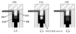
도 6은 배기밸브 감쇄장치에서의 캐비테이션 현상을 나타낸 예시도를 도시하고 있는데, 이는 도 4, 5와 같은 배기밸브 감쇄장치에서 배기밸브를 여는 과정에서 발생하는 케비테이션 현상에 관한 것이다. 배기밸브가 도 6의 (가)처럼 하강함에 따라 감쇄실린더(5102)의 체적이 증가하게 되고, 감쇄피스톤(5101)과 감쇄실린더(5102) 사이의 간극(도 5의 도면부호 5103 참조)을 통해서는 유압유가 거의 유입되지 않으므로, 감쇄실린더 내부의 유압유는 압력이 배기밸브가 하강함에 따라 점차 감소하게 된다.
이후 압력이 계속 하강하여 유압유의 증기압에 도달하게 되면, (나)처럼 감쇄 실린더(5102) 내부에는 캐1비테이션 현상이 발생하여 캐비티가 형성되게 된다.이후 배기밸브가 계속 하강하여 감쇄실린더의 내부가 외부의 오일실린더와 개방되는 순간에는 (다)와 같이 감쇄실린더 내부로 유압유가 급격히 유입되며 압력이 상승하게 되고 이는 실린더 내부에 형성된 캐비티를 붕괴시키게 된다.
감쇄실린더(5102) 내부에 캐비테이션 현상이 발생하게 되면 캐비티들이 붕괴하는 순간 급격한 압력 상승이 일어나게 되어 진동 및 소음의 발생 원인이 될 뿐만 아니라, 감쇄실린더(5102) 및 감쇄피스톤(5101) 벽면에 침식 손상을 일으키게 된다. 특히, 이러한 침식 손상은 감쇄실린더(5102)와 감쇄피스톤(5101)의 간극을 점차 크게 하여 배기밸브의 감쇄량을 떨어뜨리게 되므로, 결과적으로 배기밸브가 닫힐 때의 충격을 충분히 감쇄시키지 못하게 됨에 따라 배기밸브와 밸브시트의 손상을 야기하여 내구수명을 감소시키는 원인이 된다.
상기와 같은 문제점을 해결하기 위한 본 발명의 목적은 대형 디젤엔진의 감쇄피스톤 내부에 체크밸브를 설치하여 감쇄실린더 내부로 유압유가 쉽게 유입되도록 함으로써, 배기밸브의 열림 과정에서 감쇄실린더 내부에 발생하는 캐비테이션 현상의 발생을 방지함으로써 캐비테이션 현상에 의한 소음 및 진동 그리고 침식 손상을 방지하는 배기밸브 감쇄장치를 제공하는 데 있다.
상기한 바와 같은 목적을 달성하고 종래의 결점을 제거하기 위한 과제를 수행하는 본 발명은 감쇄피스톤과 감쇄실린더로 이루어진 배기밸브 감쇄장치에 있어서, 상기 감쇄피스톤 내부에서 양측으로 개방 형성되어 유압유가 유입되도록 한 수평유로와; 수평유로로부터 감쇄피스톤의 저면까지 관통된 수직유로와;수직유로상의 일 지점에 설치되어 압력 차이에 따라 하부방향으로 개방되어 유압유가 감쇄실린더 내부로 유입되도록 형성된 체크밸브를 포함하여 구성함으로써 캐비테이션 현상을 방지토록 한 것을 특징으로 하는 대형 디젤엔진 유압식 배기밸브 구동장치에서의 캐비테이션 방지용 배기밸브 감쇄장치를 제공함으로써 달성된다.
상기 체크밸브는 감쇄피스톤의 저면쪽 수직유로상에 나산산을 가공하고, 이 나사산과 나사결합하도록 체크밸브의 케이스 둘레방향에 나사산을 형성하여 착탈되도록 구성하고, 체크밸브 개방압력 조절시 밸브를 지지하는 스프링을 교체토록 구성한 것을 특징으로 한다. 또한 상기 체크밸브는 감쇄피스톤의 저면쪽 수직유로상에 나산산을 가공하고, 이 나사산과 나사결합하도록 체크밸브의 케이스 둘레방향에 나사산을 형성하여 착탈되도록 구성하고, 체크밸브 개방압력 조절시 밸브를 지지하는 스프링의 상면에 디스크를 삽입하거나 제거하여 조절토록 구성한 것을 특징으로 한다. 본 발명은 대형 디젤엔진의 감쇄피스톤 내부에 체크밸브를 설치하여 감쇄실린더 내부로 유압유가 쉽게 유입되도록 함으로써, 배기밸브의 열림 과정에서 감쇄실린더 내부에 발생하는 캐비테이션 현상의 발생을 방지함으로써 캐비테이션 현상에 의한 소음 및 진동을 방지하게 된다는 장점과,또한 감쇄실린더 및 감쇄피스톤 벽면에 침식 손상을 방지하게 된다는 장점과, 또한 감쇄실린더 및 감쇄피스톤 벽면에 침식 손상을 방지함으로써 감쇄실린더와 감쇄피스톤의 간극을 일정하게 유지하게 되어 지속적으로 배기밸브가 닫힐 때의 충격을 감쇄시켜 배기밸브와 밸브시트의 내구수명을 증가시킨다는 장점과, 또한 체크밸브의 개방압력을 적절하게 설정할 수 있어 체크밸브의 내구수명을 증가시켜 준다는 장점과, 또한 감쇄피스톤 내부에 설치되는 체크밸브를 나사형태로 착탈되도록 하여 손 쉽게 분해 조립이 가능한 구조로서, 체크밸브의 개방압력을 조절할 필요가 있거나 체크밸브 내부의 스프링 등 부품의 손상이 있는 경우 밸브를 분리하여 체크밸브의 개방압력을 조절하거나 쉽게 교체 가능하다는 장점과,또한 체크밸브의 스프링 시트부에 디스크를 삽입 또는 제거함으로써 체크밸브의 개방압력을 조절하거나, 필요시 스프링 장력이 다른 스프링으로 교체하여 체크밸브의 개방압력을 조절할 수 있다는 장점을 가진 유용한 발명으로 산업상 그 이용이 크게 기대되는 발명인 것이다.
도 1은 본 발명의 한 실시예에 따라 감쇄장치 내부에 유로를 형성하고 유로상에 체크밸브를 형성한 것을 보인 예시도이고,
도 2는 본 발명의 다른 실시예에 따라 감쇄장치 내부에 유로를 형성하고 유로 하부에 나사식 체크밸브를 형성한 것을 보인 예시도이고,
도 3은 본 발명의 다른 실시예에 따라 감쇄장치 내부에 유로를 형성하고 유로 하부에 장력 조절용 디스크를 적용한 나사식 체크밸브를 형성한 것을 보인 예시도이고,
도 4는 종래의 유압식 배기밸브 구동장치 및 작동을 보인 예시도이고,
도 5는 종래의 배기밸브 감쇄장치의 기능 및 작동과정을 보인 예시도이고,
도 6은 종래 배기밸브 감쇄장치에서의 캐비테이션 현상을 나타낸 예시도이다.
<도면의 주요부분에 대한 부호의 설명>
(1) : 수평유로 (2) : 수직유로
(3) : 체크밸브 (31) : 스프링
(32) : 밸브몸체 (34, 33) : 개방구
(35) : 케이스 (36) : 디스크
이하 본 발명의 실시 예인 구성과 그 작용을 첨부도면에 연계시켜 상세히 설명하면 다음과 같다. 또한 본 발명을 설명함에 있어서, 관련된 공지기능 혹은 구성에 대한 구체적인 설명이 본 발명의 요지를 불필요하게 흐릴 수 있다고 판단되는 경우 그 상세한 설명은 생략한다.
도 1은 본 발명의 한 실시예에 따라 감쇄장치 내부에 유로를 형성하고 유로상에 체크밸브를 형성한 것을 보인 예시도인데, 도시된 바와 같이 본 발명의 캐비테이션 방지 구조는 감쇄피스톤(5101) 내부에서 양측으로 개방 형성되어 유압유가 유입되도록 한 수평유로(1)와 수평유로(1)로부터 감쇄피스톤(5101)의 저면까지 관통된 수직유로(2)가 형성되고, 수직유로상의 일 지점에 설치되어 압력 차이에 따라 하부방향으로 개방되어 유압유가 감쇄실린더 내부로 유입되도록 형성된 체크밸브(3)로 구성된다.
이와 같이 감쇄피스톤(5101) 내부에 유로를 구성하고 체크밸브를 설치함으로써, 배기밸브가 하강하여 열리는 과정에서 감쇄실린더 내부의 체적이 증가하여 유압유의 압력이 감소하게 되면 압력 차이에 의해 체크밸브(3)를 구성하는 스프링(31, 도 2참조)이 하부로 밀리면서 스프링이 지지하고 있던 밸브몸체(32, 도 2참조)가 하강하여 체크밸브가 열려 감쇄실린더 외부에 있던 유압유가 밸브 상부의 개방구(33)와 밸브 몸체(32, 도 2참조)의 외부에서 내부로 관통된 유로(321, 도 2참조)를 통해 밸브 내부로 유입되어, 밸브 하부의 개방구(34, 도 2참조)를 통해 감쇄실린더(5102)로 유입되게 되므로 감쇄실린더(5102) 내부에서 캐비테이션 현상이 일어나는 것을 방지하게 된다. 이 경우 감쇄실린더(5102) 내부에서 외부의 오일실린더로는 유압유가 배출되지 못하므로, 배기밸브가 닫히는 과정에서의 감쇄 기능은 동일하게 유지된다.
도 2는 본 발명의 다른 실시예에 따라 감쇄장치 내부에 유로를 형성하고 유로 하부에 나사식 체크밸브를 형성한 것을 보인 예시도인데, 도시된 바와 같이 감쇄피스톤(5101)의 내부에 형성된 수직유로(2)상의 일 지점에 압력에 따라 하부방향으로 개방되는 체크밸브(3)를 감쇄피스톤(5101)의 저면쪽 수직유로상에 나산산(도시없음)을 가공하고, 이에 나사결합하여 체결하도록 체크밸브(3)의 케이스(35) 둘레방향에 나사산(도시없음)을 형성하여 나사결합에 의해 착탈식으로 구성한 것을 도시하고 있다. 이와 같이 나사결합에 의한 착탈식으로 구성한 이유는 체크밸브(3)의 개방압력을 가능한 낮게 설정하여 감쇄실린더(5102) 내부의 압력이 떨어지면 체크밸브가 즉시 열려 유압유가 유입되게 하는 것이 좋으나, 개방압력이 너무 낮게 설정되면 작은 압력변동에도 밸브가 자주 개폐되게 되므로, 체크밸브의 내구수명이 감소하는 문제가 발생할 수 있으므로, 이를 고려하여 밸브의 개방압력을 적절하게 설정해 주어야 한다. 이러한 개방압력 조절 방법은 나사결합된 체크밸브를 감쇄피스톤(5101)으로부터 분리 후 필요로 하는 장력을 가진 스프링으로 교체하면 된다.
즉, 감쇄피스톤 내부에 설치되는 체크밸브는 나사형태 등으로 손쉽게 분해 조립이 가능한 구조로서, 체크밸브의 개방압력을 조절할 필요가 있거나 체크밸브 내부의 스프링 등 부품의 손상이 있는 경우 밸브를 분리하여 체크밸브의 개방압력을 조절하거나 쉽게 교체 가능하면 된다.
도 3은 본 발명의 다른 실시예에 따라 감쇄장치 내부에 유로를 형성하고 유로 하부에 장력 조절용 디스크를 적용한 나사식 체크밸브를 형성한 것을 보인 예시도인데, 나사식으로 형성된 체크밸브(3)의 내부에 형성된 밸브몸체(32)를 지지하는 스프링(31)의 상면 시트부에 장력 조절용 디스크(36)가 삽입 구성되어 있음을 알 수 있다.
이와 같이 구성함으로써 도 2와 같이 체크밸브의 개방압력 조절을 위해 스프링을 교체하기 전에 장력조절이 필요할 경우 체크밸브의 스프링 상면에 디스크를 삽입하여 장력을 강화하던가, 아니면 처음에 삽입되어 있던 디스크(36)를 제거함으로써 체크밸브의 개방압력을 조절할 수 있게 된다. 물론 이와 같은 방법으로 조절되기 어려울 경우에는 도 2에 도시된 바와 같이 체크밸브를 분리 후 적당한 장력을 가진 다른 스프링으로 교체하여 체크밸브의 개방압력을 조절하면 된다.
본 발명은 상술한 특정의 바람직한 실시 예에 한정되지 아니하며, 청구범위에서 청구하는 본 발명의 요지를 벗어남이 없이 당해 발명이 속하는 기술분야에서 통상의 지식을 가진 자라면 누구든지 다양한 변형실시가 가능한 것은 물론이고, 그와 같은 변경은 청구범위 기재의 범위 내에 있게 된다.
Claims (3)
- 감쇄피스톤과 감쇄실린더로 이루어진 배기밸브 감쇄장치에 있어서,상기 감쇄피스톤 내부에서 양측으로 개방 형성되어 유압유가 유입되도록 한수평유로(1)와;수평유로(1)로부터 감쇄피스톤의 저면까지 관통된 수직유로(2)와;수직유로상의 일 지점에 설치되어 압력 차이에 따라 하부방향으로 개방되어유압유가 감쇄실린더 내부로 유입되도록 형성된 체크밸브(3);를 포함하여 구성함으로써 캐비테이션 현상을 방지토록 한 것을 특징으로 하는 대형 디젤엔진 유압식 배기밸브 구동장치에서의 캐비테이션 방지용 배기밸브 감쇄장치.
- 제 1항에 있어서,상기 체크밸브는 감쇄피스톤의 저면쪽 수직유로상에 나산산을 가공하고, 이나사산과 나사결합하도록 체크밸브(3)의 케이스(35) 둘레방향에 나사산을 형성하여착탈되도록 구성하고, 체크밸브 개방압력 조절시 밸브몸체를 지지하는 스프링을 교체토록 구성한 것을 특징으로 하는 대형 디젤엔진 유압식 배기밸브 구동장치에서의캐비테이션 방지용 배기밸브 감쇄장치.
- 제 1항 또는 2항에 있어서,상기 체크밸브는 감쇄피스톤의 저면쪽 수직유로상에 나산산을 가공하고, 이나사산과 나사결합하도록 체크밸브(3)의 케이스(35) 둘레방향에 나사산을 형성하여착탈되도록 구성하고, 체크밸브 개방압력 조절시 밸브몸체를 지지하는 스프링의 상면에 디스크(36)를 삽입하거나 제거하여 조절토록 구성한 것을 특징으로 하는 대형디젤엔진 유압식 배기밸브 구동장치에서의 캐비테이션 방지용 배기밸브 감쇄장치.
Applications Claiming Priority (2)
| Application Number | Priority Date | Filing Date | Title |
|---|---|---|---|
| KR1020080105084A KR20100046307A (ko) | 2008-10-27 | 2008-10-27 | 대형 디젤엔진 유압식 배기밸브 구동장치에서의 캐비테이션방지용 배기밸브 감쇄장치 |
| KR10-2008-0105084 | 2008-10-27 |
Publications (2)
| Publication Number | Publication Date |
|---|---|
| WO2010050701A2 true WO2010050701A2 (ko) | 2010-05-06 |
| WO2010050701A3 WO2010050701A3 (ko) | 2010-08-05 |
Family
ID=42129428
Family Applications (1)
| Application Number | Title | Priority Date | Filing Date |
|---|---|---|---|
| PCT/KR2009/006140 Ceased WO2010050701A2 (ko) | 2008-10-27 | 2009-10-22 | 대형 디젤엔진 유압식 배기밸브 구동장치에서의 캐비테이션 방지용 배기밸브 감쇄장치 |
Country Status (2)
| Country | Link |
|---|---|
| KR (1) | KR20100046307A (ko) |
| WO (1) | WO2010050701A2 (ko) |
Cited By (1)
| Publication number | Priority date | Publication date | Assignee | Title |
|---|---|---|---|---|
| CN118275293A (zh) * | 2024-06-03 | 2024-07-02 | 湖南工商大学 | 多工况模拟环管试验装置 |
Family Cites Families (4)
| Publication number | Priority date | Publication date | Assignee | Title |
|---|---|---|---|---|
| JPS6085208A (ja) * | 1983-10-14 | 1985-05-14 | Mitsubishi Heavy Ind Ltd | 油圧弁駆動装置 |
| JPH057451Y2 (ko) * | 1987-05-19 | 1993-02-25 | ||
| KR19980064309U (ko) * | 1997-04-28 | 1998-11-25 | 김영귀 | 체크 밸브의 크랙킹 압력 조정 너트 |
| JPH1122432A (ja) * | 1997-07-03 | 1999-01-26 | Nippon Soken Inc | 電磁式弁駆動装置 |
-
2008
- 2008-10-27 KR KR1020080105084A patent/KR20100046307A/ko not_active Ceased
-
2009
- 2009-10-22 WO PCT/KR2009/006140 patent/WO2010050701A2/ko not_active Ceased
Cited By (1)
| Publication number | Priority date | Publication date | Assignee | Title |
|---|---|---|---|---|
| CN118275293A (zh) * | 2024-06-03 | 2024-07-02 | 湖南工商大学 | 多工况模拟环管试验装置 |
Also Published As
| Publication number | Publication date |
|---|---|
| WO2010050701A3 (ko) | 2010-08-05 |
| KR20100046307A (ko) | 2010-05-07 |
Similar Documents
| Publication | Publication Date | Title |
|---|---|---|
| CN105673214B (zh) | 利用减压的发动机制动器的复位装置 | |
| WO2010050701A2 (ko) | 대형 디젤엔진 유압식 배기밸브 구동장치에서의 캐비테이션 방지용 배기밸브 감쇄장치 | |
| WO2010093081A1 (ko) | 자동차 벨트 드라이브용 유압식 오토텐셔너 | |
| WO2010050703A3 (ko) | 디젤엔진 연료분사펌프의 캐비테이션 손상방지장치 | |
| KR101693888B1 (ko) | 오일컨트롤밸브 | |
| WO2016056859A1 (ko) | 오일펌프 컨트롤 밸브 | |
| KR101681846B1 (ko) | 차량 엔진의 블로바이가스 채널 구조 | |
| TWI461620B (zh) | 釋放閥 | |
| CN209990934U (zh) | 一种限压阀柱塞和避免压力波动的机油泵限压阀 | |
| CN110566713B (zh) | 一种排气阀驱动机构及排气阀 | |
| CN105134548B (zh) | 一种用于氧弹的活塞式充氧排气装置 | |
| CN102032015B (zh) | 防窜油的安全机油泵 | |
| EP2226483B1 (en) | Variable compression ratio internal combustion engine and method for discharging coolant from variable compression ratio internal combustion engine | |
| WO2010050702A2 (ko) | 대형 디젤엔진의 배기밸브 닫힘시의 감쇄량 조절 장치 | |
| KR20210156998A (ko) | 블로바이가스 벤틸레이션 시스템 | |
| KR20050034791A (ko) | 오일 세퍼레이터 | |
| KR100941194B1 (ko) | 오일 세퍼레이터 | |
| CN110925369B (zh) | 一种正时紧链器 | |
| CN202544963U (zh) | 一种柴油机曲轴箱通风装置 | |
| JP5187149B2 (ja) | 内燃機関の動弁駆動装置 | |
| KR101839900B1 (ko) | 차량용 오일 세퍼레이터 | |
| JP2001123856A (ja) | バルブスプリング荷重の可変制御装置とその制御方法 | |
| WO2011145800A1 (ko) | 솔레노이드와 시트형 스풀을 이용한 전자식 연료분사밸브 | |
| KR101543130B1 (ko) | 자동차의 터보차저 오일 공급 가변 장치 | |
| WO2013062343A2 (ko) | 디젤엔진의 연료분사노즐 |
Legal Events
| Date | Code | Title | Description |
|---|---|---|---|
| 121 | Ep: the epo has been informed by wipo that ep was designated in this application |
Ref document number: 09823781 Country of ref document: EP Kind code of ref document: A2 |
|
| NENP | Non-entry into the national phase |
Ref country code: DE |
|
| 32PN | Ep: public notification in the ep bulletin as address of the adressee cannot be established |
Free format text: NOTING OF LOSS OF RIGHTS PURSUANT TO RULE 112(1) EPC (EPO FORM 1205A SEND 23-08-11) |
|
| 122 | Ep: pct application non-entry in european phase |
Ref document number: 09823781 Country of ref document: EP Kind code of ref document: A2 |