WO2010050182A1 - Agitation device, melting apparatus and melting method - Google Patents
Agitation device, melting apparatus and melting method Download PDFInfo
- Publication number
- WO2010050182A1 WO2010050182A1 PCT/JP2009/005655 JP2009005655W WO2010050182A1 WO 2010050182 A1 WO2010050182 A1 WO 2010050182A1 JP 2009005655 W JP2009005655 W JP 2009005655W WO 2010050182 A1 WO2010050182 A1 WO 2010050182A1
- Authority
- WO
- WIPO (PCT)
- Prior art keywords
- molten metal
- melting
- outer plate
- magnetic field
- tank
- Prior art date
Links
Images


Classifications
-
- B—PERFORMING OPERATIONS; TRANSPORTING
- B22—CASTING; POWDER METALLURGY
- B22D—CASTING OF METALS; CASTING OF OTHER SUBSTANCES BY THE SAME PROCESSES OR DEVICES
- B22D1/00—Treatment of fused masses in the ladle or the supply runners before casting
-
- B—PERFORMING OPERATIONS; TRANSPORTING
- B22—CASTING; POWDER METALLURGY
- B22D—CASTING OF METALS; CASTING OF OTHER SUBSTANCES BY THE SAME PROCESSES OR DEVICES
- B22D46/00—Controlling, supervising, not restricted to casting covered by a single main group, e.g. for safety reasons
-
- C—CHEMISTRY; METALLURGY
- C22—METALLURGY; FERROUS OR NON-FERROUS ALLOYS; TREATMENT OF ALLOYS OR NON-FERROUS METALS
- C22B—PRODUCTION AND REFINING OF METALS; PRETREATMENT OF RAW MATERIALS
- C22B21/00—Obtaining aluminium
- C22B21/0084—Obtaining aluminium melting and handling molten aluminium
-
- C—CHEMISTRY; METALLURGY
- C22—METALLURGY; FERROUS OR NON-FERROUS ALLOYS; TREATMENT OF ALLOYS OR NON-FERROUS METALS
- C22B—PRODUCTION AND REFINING OF METALS; PRETREATMENT OF RAW MATERIALS
- C22B21/00—Obtaining aluminium
- C22B21/0084—Obtaining aluminium melting and handling molten aluminium
- C22B21/0092—Remelting scrap, skimmings or any secondary source aluminium
-
- C—CHEMISTRY; METALLURGY
- C22—METALLURGY; FERROUS OR NON-FERROUS ALLOYS; TREATMENT OF ALLOYS OR NON-FERROUS METALS
- C22B—PRODUCTION AND REFINING OF METALS; PRETREATMENT OF RAW MATERIALS
- C22B9/00—General processes of refining or remelting of metals; Apparatus for electroslag or arc remelting of metals
- C22B9/003—General processes of refining or remelting of metals; Apparatus for electroslag or arc remelting of metals by induction
-
- F—MECHANICAL ENGINEERING; LIGHTING; HEATING; WEAPONS; BLASTING
- F27—FURNACES; KILNS; OVENS; RETORTS
- F27B—FURNACES, KILNS, OVENS, OR RETORTS IN GENERAL; OPEN SINTERING OR LIKE APPARATUS
- F27B3/00—Hearth-type furnaces, e.g. of reverberatory type; Tank furnaces
- F27B3/10—Details, accessories, or equipment peculiar to hearth-type furnaces
- F27B3/20—Arrangements of heating devices
- F27B3/205—Burners
-
- F—MECHANICAL ENGINEERING; LIGHTING; HEATING; WEAPONS; BLASTING
- F27—FURNACES; KILNS; OVENS; RETORTS
- F27D—DETAILS OR ACCESSORIES OF FURNACES, KILNS, OVENS, OR RETORTS, IN SO FAR AS THEY ARE OF KINDS OCCURRING IN MORE THAN ONE KIND OF FURNACE
- F27D27/00—Stirring devices for molten material
-
- Y—GENERAL TAGGING OF NEW TECHNOLOGICAL DEVELOPMENTS; GENERAL TAGGING OF CROSS-SECTIONAL TECHNOLOGIES SPANNING OVER SEVERAL SECTIONS OF THE IPC; TECHNICAL SUBJECTS COVERED BY FORMER USPC CROSS-REFERENCE ART COLLECTIONS [XRACs] AND DIGESTS
- Y02—TECHNOLOGIES OR APPLICATIONS FOR MITIGATION OR ADAPTATION AGAINST CLIMATE CHANGE
- Y02P—CLIMATE CHANGE MITIGATION TECHNOLOGIES IN THE PRODUCTION OR PROCESSING OF GOODS
- Y02P10/00—Technologies related to metal processing
- Y02P10/20—Recycling
-
- Y—GENERAL TAGGING OF NEW TECHNOLOGICAL DEVELOPMENTS; GENERAL TAGGING OF CROSS-SECTIONAL TECHNOLOGIES SPANNING OVER SEVERAL SECTIONS OF THE IPC; TECHNICAL SUBJECTS COVERED BY FORMER USPC CROSS-REFERENCE ART COLLECTIONS [XRACs] AND DIGESTS
- Y02—TECHNOLOGIES OR APPLICATIONS FOR MITIGATION OR ADAPTATION AGAINST CLIMATE CHANGE
- Y02P—CLIMATE CHANGE MITIGATION TECHNOLOGIES IN THE PRODUCTION OR PROCESSING OF GOODS
- Y02P10/00—Technologies related to metal processing
- Y02P10/25—Process efficiency
Definitions
- the present invention introduces a material to be melted (for example, cutting scraps of non-ferrous metal such as aluminum or magnesium) into the molten metal and stirs the molten metal, a melting device having the stirring device, and the molten material to the molten metal.
- the present invention relates to a melting method for dissolving a material to be dissolved by adding and stirring the molten metal.
- the tool or propeller comes into contact with the hot molten metal, and the tool or propeller is worn out. Therefore, it is necessary to frequently replace these instruments or propellers, and there is a problem that maintenance becomes complicated.
- the methods (1) and (2) have a problem that the quality of the molten metal may be deteriorated (which may cause contamination of the molten metal) due to mixing of worn components or propeller components into the molten metal.
- Patent Literature 1 methods of melting aluminum by putting aluminum cutting waste into the molten metal and stirring the molten metal.
- Patent Document 1 the internal space of the reflection furnace is divided into four parts, a melting chamber, an open well portion, a vortex generating chamber, and a molten metal passage, and these are communicated with each other.
- an electromagnetic stirrer consisting of an induction coil at the bottom of the molten metal passage and applying electromagnetic force to the molten metal in the molten metal passage, the molten metal is melted in the molten metal passage ⁇ melting chamber ⁇ open well portion ⁇ Circulate in the order of vortex generation chamber ⁇ molten metal passage ⁇ .
- an opening is formed at the bottom of the vortex generating chamber, and the vortex generating chamber and the molten metal passage are communicated with each other through the opening.
- a vortex flow is generated on the liquid surface of the molten metal in the vortex generating chamber.
- the aluminum-based metal cutting waste is dissolved by entraining the aluminum-based metal cutting waste in this vortex.
- the electromagnetic stirrer generates a force sufficient to circulate all the molten metal in the reflection furnace. Therefore, it is necessary to supply a large amount of power to the electromagnetic stirrer. Have the problem that there is.
- the aluminum-based metal cutting waste floats on the liquid surface of the molten metal. As a result, it is not easily dissolved.
- aluminum-based metal cutting scraps have a large surface area, and an oxide film having a high melting point is formed on the surface due to temperature rise, so that melting is difficult.
- the aluminum-based metal cutting waste stays floating on the surface of the molten metal, so that the oxidation (combustion) of the aluminum-based metal cutting waste proceeds, and as a result, the aluminum-based metal cutting waste is re-melted to recycle. Yield decreases.
- Patent Document 1 since the molten metal moves to the molten metal passage through the opening formed in the bottom of the vortex generating chamber, finally, the aluminum-based metal cutting waste is removed. It is possible to forcibly entrain the molten metal, but in order to generate a strong eddy current, it is necessary to reduce the cross-sectional area of the opening at the bottom of the vortex generating chamber to a certain extent, and a large amount of aluminum-based metal cutting waste is contained in the molten metal. When they are simultaneously added, undissolved aluminum-based metal cutting waste rushes into the opening and becomes clogged in the opening.
- JP-A-2-17934 Japanese Patent Laid-Open No. 2-219978 JP-A-2-23232323
- the present invention has been made in view of the above circumstances, and provides a stirring device, a melting device, and a melting method that do not contaminate the molten metal and have high melting efficiency.
- the stirring device is a stirring device that promotes dissolution of the melted material by stirring the molten metal charged with the melted material, and is a melting tank that stores the melt.
- a moving magnetic field generator for generating a magnetic field which is arranged outside and moves downward along the side wall of the dissolution tank is generated inside the dissolution tank.
- the moving magnetic field generator has a magnetic field that moves upward along the side wall of the dissolution tank at a predetermined distance from the downward movement magnetic field in the dissolution tank. Preferably it occurs.
- the moving magnetic field generator includes a permanent magnet facing the side wall of the melting tank, a support member that supports the permanent magnet, and a motor that rotationally drives the support member. Furthermore, it is preferable that the rotating shaft of the motor is disposed at a position lower than the liquid level of the molten metal by a predetermined distance.
- the moving magnetic field generator includes a liquid surface position detecting device that detects a position of a liquid surface of the molten metal, an elevating device that supports the motor to be raised and lowered, and the liquid surface.
- a liquid surface position detecting device that detects a position of a liquid surface of the molten metal
- an elevating device that supports the motor to be raised and lowered
- the liquid surface By transmitting a signal for raising or lowering the motor to the elevating device based on the position of the liquid level of the molten metal detected by the position detecting device, relative to the liquid level of the molten metal in the vertical direction
- a control device for controlling the general position.
- the control device causes the lifting device to hold the position of the rotating shaft of the motor at a position lower by a predetermined distance than the position of the liquid level of the molten metal detected by the liquid level position detecting device. It is preferable to send a signal to raise or lower the motor.
- the moving magnetic field generator includes a plurality of electromagnetic coils arranged along a side wall of the dissolution tank, and a power supply device that sequentially supplies power to the plurality of electromagnetic coils. It is preferable to provide.
- the present invention is disposed at a position corresponding to a magnetic field that moves downward along the side wall of the dissolution tank generated by the moving magnetic field generator inside the dissolution tank, and on the side wall and the horizontal plane of the dissolution tank. It is preferable to provide a first molten metal rectifying member having a first molten metal rectifying surface perpendicular to the first molten metal. It is particularly preferable that the first molten metal rectifying surface has a shape in which a central portion is depressed in a plan view.
- the second molten metal rectifying surface is disposed in the melting tank and at a position opposite to the moving magnetic field generator across the side wall of the melting tank and parallel to the side wall of the melting tank.
- straightening member which has this is comprised.
- a melting apparatus is a melting apparatus for melting a material to be melted by putting the material to be melted into molten metal stored in a melting tank, Such a stirring device is provided.
- the stirring method according to the third aspect of the present invention includes a charging step of charging a material to be melted into molten metal stored in a melting tank, and a magnetic field that moves downward along the side wall of the melting tank. And a stirring step of stirring the molten metal.
- a magnetic field that moves upward along the side wall of the dissolution tank is generated inside the dissolution tank at a position that is a predetermined distance away from the magnetic field that moves downward. It is preferable.
- the agitation step includes a permanent magnet facing the side wall of the dissolution tank, a support member that supports the permanent magnet, and a motor that rotationally drives the support member, and the dissolution
- a moving magnetic field generator arranged outside the tank, a magnetic field that moves downward along the side wall of the dissolution tank is generated.
- the stirring step includes a plurality of electromagnetic coils arranged along a side wall of the dissolution tank, and a power supply device that sequentially supplies power to the plurality of electromagnetic coils. It is preferable to generate a magnetic field that moves downward along the side wall of the dissolution tank by using a moving magnetic field generator disposed outside the dissolution tank.
- a first molten metal rectifying member having a first molten metal rectifying surface perpendicular to a side wall and a horizontal surface of the molten tank is provided inside the melting tank and the melting tank. It is preferable to arrange at a position corresponding to the magnetic field moving downward along the side wall. Furthermore, it is particularly preferable that the first molten metal rectifying surface has a shape in which a central portion is depressed in a plan view.
- a second molten metal rectifying member having a second molten metal rectifying surface parallel to the side wall of the melting tank is sandwiched between the inside of the melting tank and the side wall of the melting tank. It is preferable to arrange at the position opposite to the moving magnetic field generator.
- a stirrer is a stirrer that promotes dissolution of the melt by stirring the molten metal charged with the melt, and is a melting tank that stores the melt.
- a moving magnetic field generator for generating a magnetic field that is arranged outside and moves downward along the side wall of the dissolution tank, and a moving magnetic field generation device that is disposed inside the dissolution tank, and that has a space inside the dissolution tank.
- a charging / floating partition member that divides into two spaces communicating with each other in the lower part, and of the two spaces partitioned by the charging / floating partition member, the space closer to the moving magnetic field generator is dissolved
- a charging / dissolving chamber that is a space for charging the material to be melted into the molten metal in a tank, and a space farther from the moving magnetic field generator among the two spaces partitioned by the charging / floating partition member Covered The space in which suspended matter recovery chamber for recovering floating matter generated by dissolution of the hydrolyzate.
- the melting tank is disposed at a position farther from the moving magnetic field generator than the charging / floating partition member, and in the space inside the melting tank, from the charging / floating partition member.
- a floating / molten metal partition member that divides a portion far from the moving magnetic field generating device into two spaces communicating with each other in the lower part, and the moving magnetic field generating device out of the two spaces partitioned by the floating / molten metal partitioning member A space closer to the moving magnetic field generator among the two spaces partitioned by the floating / molten metal partitioning member is used to collect the molten metal from the melting tank. It is preferable that the molten metal recovery chamber be a space.
- a melting apparatus is a melting apparatus that melts the material to be melted by introducing the material to be melted into molten metal stored in a melting tank. Such a stirring device is provided.
- a melting apparatus includes a melting tank provided with an outer plate made of a metal material and a refractory material covering an inner plate surface of the outer plate, and an outer plate of the melting tank. And a moving magnetic field generator that stirs the molten metal stored in the melting tank by generating a magnetic field that moves along the outer plate in the melting tank, and is stored in the melting tank.
- a melting device that melts the material to be melted by introducing the material to be melted, wherein the moving magnetic field generator includes a permanent magnet that faces the outer plate of the melting tank, and a support that supports the permanent magnet.
- a member, and a motor that rotates the support member around a rotation axis perpendicular to the outer plate surface of the outer plate, and a portion of the outer plate of the dissolution tank facing the permanent magnet includes Larger than the metal material that forms the outer plate of the melting tank A resistance band having electrical resistance is formed, a middle portion of the resistance band is disposed at a position facing the rotating shaft in the outer plate of the dissolution tank, and an end of the resistance band is the outer plate of the dissolution tank. It arrange
- the N pole and the S pole of the permanent magnet may be arranged at positions 180 degrees out of phase with respect to the rotation axis as seen from the axial direction of the rotation axis. preferable.
- the resistance band is a groove formed in the outer plate of the melting tank.
- a portion of the outer plate of the melting tank facing the permanent magnet has an electric resistance larger than that of the metal material constituting the outer plate of the melting tank and is separated from the resistance band. It is preferable that the sub resistance band arranged in the above is formed.
- the sub resistance band is preferably a groove formed in an outer plate of the melting tank.
- the melting method according to the seventh aspect of the present invention includes a melting tank provided with an outer plate made of a metal material and a refractory material covering the inner plate surface of the outer plate, and an outer side of the outer plate of the melting tank. And a moving magnetic field generator that stirs the molten metal stored in the melting tank by generating a magnetic field that moves along the outer plate in the melting tank, and is stored in the melting tank.
- the outer plate of the dissolution tank A resistance band having an electric resistance larger than that of the metal material is formed, a midway part of the resistance band is disposed at a position facing the rotation axis in the outer plate of the melting tank, and an end of the resistance band is disposed in the melting tank
- the outer plate is disposed at a position away from the position facing the rotation shaft.
- the N pole and the S pole of the permanent magnet may be arranged at positions 180 degrees out of phase with respect to the rotation axis as seen from the axial direction of the rotation axis. preferable.
- the resistance band is preferably a groove formed in the outer plate of the dissolution tank.
- a portion of the outer plate of the melting tank facing the permanent magnet has an electric resistance larger than that of the metal material constituting the outer plate of the melting tank and is separated from the resistance band. It is preferable to form the sub resistance bands arranged in the same manner.
- the auxiliary resistance band is preferably a groove formed in the outer plate of the melting tank.
- the present invention has an effect that the molten metal is not contaminated and the melting efficiency is good.
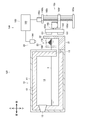
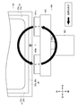
- the melting furnace 100 which is 1st embodiment of the melting apparatus which concerns on this invention using FIGS. 1-6 is demonstrated.
- the “vertical direction” is defined based on the direction in which gravity acts (the direction in which gravity acts is defined as the downward direction), and the “front / rear direction” is defined as the direction perpendicular to the vertical direction.
- the “left-right direction” is defined as a direction perpendicular to the up-down direction and the front-rear direction, and explanation will be made using these directions.
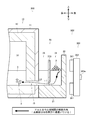
- the melting furnace 100 is a device that generates molten metal 3 by melting aluminum cutting waste 2, and includes a main body 10, a charging tank 20, and a stirring device 150.
- the aluminum cutting waste 2 is an embodiment of an object to be melted according to the present invention, and is an object to be melted by the melting furnace 100.
- the aluminum cutting waste 2 is made of an aluminum alloy.
- the shape of the aluminum cutting waste 2 is bowl-shaped (elongated shape), and the size of the aluminum cutting waste 2 is about 1 mm to 10 cm.
- the aluminum cutting waste 2 is generated by cutting a part (for example, an engine block) made of an aluminum alloy.
- the material which comprises the to-be-dissolved material which concerns on this invention is not limited to the aluminum alloy which is the material which comprises the aluminum cutting waste 2.
- FIG. Examples of the material constituting the material to be dissolved according to the present invention include various metal materials such as pure aluminum, aluminum alloy, pure magnesium, magnesium alloy, pure titanium, and titanium alloy.
- pure aluminum, aluminum alloy, pure magnesium, and magnesium alloy are non-magnetic when solid, have a relatively low melting point compared to other metal materials, have a relatively low specific gravity, and are liquids of molten metal. It is more preferable to apply the stirrer, the dissolution apparatus, and the dissolution method according to the present invention because they easily float on the surface and easily form a high melting point oxide film on the surface.
- the shape of the material to be melted according to the present invention is not limited to the shape of the aluminum cutting waste 2.
- the shape of the material to be dissolved according to the present invention may be other shapes such as a spherical shape or a lump shape.
- the size of the material to be melted according to the present invention is not limited to the size of the aluminum cutting waste 2.
- a material having a size of less than 1 mm such as a fine powder of an aluminum alloy or a material having a size exceeding 10 cm such as a cut piece of an aluminum alloy part is also included in the melted material according to the present invention.
- the molten metal 3 refers to a liquid obtained by melting the aluminum cutting waste 2.
- the molten metal which concerns on this invention should just be a liquid which consists of substantially the same material (in the case of an alloy, substantially the same composition) as a to-be-melted material. That is, the molten metal (initial molten metal) into which the material to be melted is introduced at the start of melting is different from the method for melting the material to be melted (for example, a method for melting an ingot made of substantially the same material as the material to be melted). ).
- the main body 10 maintains the temperature of the molten metal 3 at a temperature higher than the solidification temperature.
- the main body 10 includes a structure 11, a refractory / heat insulating material 12, and a burner 13.
- the structure 11 is a substantially rectangular parallelepiped box-shaped member.
- the fireproof and heat insulating material 12 is a member made of ceramics or the like, and covers the inner peripheral surface of the structure 11 by being fixed to the inner peripheral surface of the structure 11.
- a holding chamber 14 is formed inside the structure 11 as a space surrounded by the fireproof and heat insulating material 12, and a communication path 15 is formed at the lower part of the rear surface of the structure 11.
- the molten metal 3 is stored in the lower half of the holding chamber 14.
- the burner 13 is provided in the upper part of the inner peripheral surface in front of the structure 11 and raises the temperature of the air inside the holding chamber 14 and eventually the molten metal 3 (the molten metal 3 in contact with the air) stored in the lower half of the holding chamber 14. To do.
- the temperature of the molten metal 3 is raised by the burner 13, but the present invention is not limited to this, and the molten metal may be heated using another heat source (for example, an electric heater or the like).
- the charging tank 20 is a part for charging the aluminum cutting waste 2 in the melting furnace 100.
- the charging tank 20 is fixed to the rear end portion of the main body 10.
- the charging tank 20 includes a bottom floor 21 and side walls 22.
- the bottom floor 21 is a substantially rectangular plate-like portion in plan view that extends rearward from the rear end of the structure 11 in the charging tank 20.
- the side wall 22 is a plate-like portion erected along the left end portion, the rear end portion, and the right end portion of the bottom floor 21 in the charging tank 20.
- the left front end and the right front end of the side wall 22 extend to the rear left end and the rear right end of the structure 11, respectively.
- An input chamber 23 is formed as a space surrounded by the bottom floor 21, the side wall 22, and the rear surface of the structure 11 in the input tank 20.
- the molten metal 3 is stored in the lower half of the charging chamber 23.
- the holding chamber 14 and the charging chamber 23 are communicated with each other through a communication path 15, and the molten metal 3 can move between the holding chamber 14 and the charging chamber 23 through the communication path 15.
- the top surface of the charging tank 20 is open, and the aluminum cutting waste 2 is charged into the charging chamber 23 through the opening (more strictly speaking, a first molten metal rectifying member 170 and a second molten metal rectifying member described later in plan view). 180 and the portion surrounded by the side wall 22).
- the aluminum cutting waste 2 charged into the charging chamber 23 is heated in contact with the molten metal 3 stored in the lower half of the charging chamber 23 and melts when the temperature reaches the melting point or higher.
- the inner peripheral surface is the refractory / heat insulating material 12.
- Both “covered structure 11” and “input tank 20” correspond to an embodiment of the dissolution tank according to the present invention.
- the stirrer 150 is a first embodiment of the stirrer according to the present invention.
- the stirrer 150 agitates the molten metal 3 into which the aluminum cutting waste 2 is charged (the molten metal 3 stored in the lower half of the charging chamber 23), thereby producing aluminum. It is an apparatus that promotes dissolution of the cutting waste 2.
- the stirring device 150 includes a moving magnetic field generator 160, a first molten metal rectifying member 170, and a second molten metal rectifying member 180.
- the moving magnetic field generator 160 is an embodiment of the moving magnetic field device according to the present invention.
- ( ⁇ ) A magnetic field that moves downward along the rear side wall 22 and ( ⁇ ) an upward direction along the rear side wall 22. This is a device that generates a magnetic field that moves to the inside of the charging tank 20.
- the moving magnetic field generator 160 is disposed outside the charging tank 20 (in this embodiment, behind the charging tank 20).
- the moving magnetic field generation device 160 includes permanent magnets 161 and 161, a support member 162, a motor 163, a liquid level position detection device 164, a lifting device 165, and a control device 166.
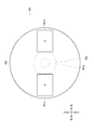
- the permanent magnets 161 and 161 are an embodiment of the permanent magnet according to the present invention, and are opposed to the rear side wall 22 as shown in FIGS.
- a “permanent magnet” refers to an object that can retain its properties as a magnet for a relatively long period of time even when no magnetic field or current is supplied from the outside.
- Specific examples of the permanent magnet according to the present invention include alnico magnet, KS steel, MK steel, ferrite magnet, samarium cobalt magnet, neodymium magnet and the like.
- the permanent magnets 161 and 161 are composed of neodymium magnets from the viewpoint of generating a strong magnetic force.
- the moving magnetic field generator 160 includes two permanent magnets 161 and 161, but the present invention is not limited to this, and the number of permanent magnets included in the moving magnetic field generator according to the present invention is as follows. It may be singular or plural.
- the support member 162 is an embodiment of the support member according to the present invention, and supports the permanent magnets 161 and 161.
- the support member 162 according to the present embodiment is a substantially disk-shaped member, and is disposed so that the disk surface thereof is parallel to the rear side wall 22.
- the permanent magnets 161 and 161 are fixed to the board surface of the support member 162 facing the rear side wall 22 at positions equidistant from the center of the board surface with the center of the board surface interposed therebetween.
- the motor 163 is an embodiment of the motor according to the present invention, and rotationally drives the support member 162 and eventually the permanent magnets 161 and 161 fixed to the support member 162.
- a rotation shaft 163 a of the motor 163 is fixed to the support member 162.
- the axis of the rotation shaft 163a and the center line of the support member 162 fixed to the rotation shaft 163a (line passing through the center of the pair of board surfaces of the support member 162) are in a straight line.
- the motor 163 of this embodiment is an electric motor
- the motor according to the present invention is not limited to this, and may be a motor that is driven to rotate by fluid pressure (for example, a hydraulic motor, a pneumatic motor, or the like). good.
- the rotating shaft 163a, the supporting member 162 fixed to the rotating shaft 163a, and the permanent magnets 161 and 161 fixed to the supporting member 162 rotate integrally (in this embodiment, the permanent magnet 161 and 161 rotate counterclockwise in rear view).
- the rear side wall 22 moves substantially downward along the rear side wall 22 into the charging tank 20 corresponding to the portion facing the left half of the support member 162.
- the charging tank 20 corresponding to a portion facing the right half of the support member 162 (that is, a position away from the magnetic field moving downward by a predetermined distance) on the side wall 22 on the rear side.
- a magnetic field that moves generally upward along the line will be generated.
- a flow (melt flow) of the molten metal 3 that circulates around an axis (in the present embodiment, the rotation shaft 163 a of the motor 163) that is substantially parallel to the liquid level of the molten metal 3 is generated in the molten metal 3.
- the aluminum cutting waste 2 moves on the flow of the molten metal 3 (melt flow), and the flow of the molten metal 3 generally downward (melt flow).
- the molten metal 3 enters the molten metal 3 (immersed in the molten metal 3) and receives heat from the molten metal 3 to melt.
- the molten metal 3 in the vicinity of the position where the aluminum cutting waste 2 is melted decreases due to melting of the aluminum cutting waste 2, the molten metal 3 is agitated by the flow of the molten metal 3 (melt flow).
- the temperature of 3 is kept substantially uniform.
- the liquid surface position detection device 164 is an embodiment of the liquid surface position detection device according to the present invention, and detects the position of the liquid surface of the molten metal 3. As shown in FIG. 1, the liquid level position detection device 164 is disposed above the charging tank 20 and thus above the liquid level of the molten metal stored in the charging chamber 23, and transmits ultrasonic waves toward the liquid level of the molten metal 3 ( Irradiation) and receiving the ultrasonic wave reflected by the liquid surface of the molten metal 3 and detecting the position of the liquid surface based on the speed of the ultrasonic wave and the time from transmission of the ultrasonic wave toward the liquid surface of the molten metal 3 until reception.
- the position (height) of the liquid surface of the molten metal 3 is detected by calculating the distance from the device 164 to the liquid surface of the molten metal 3.
- the liquid level position detection device according to the present invention is not limited to the configuration for detecting the position of the liquid level of the molten metal using ultrasonic waves, such as the liquid level position detection device 164 of the present embodiment. A configuration for detecting the position of the liquid level may also be used.
- the lifting device 165 is an embodiment of the lifting device according to the present invention, and supports the motor 163 so that the motor 163 can be raised and lowered. As shown in FIG. 1, the lifting device 165 includes a base member 165a, a support member 165b, a top member 165c, a ball screw 165d, a servo motor 165e, and a slide member 165f.
- the base member 165a is a plate-like member that forms the lower part of the lifting device 165.
- the base member 165a is fixed to the floor surface, the ground, or other structures.
- the support member 165b is a substantially cylindrical member.
- One end (lower end) of the column member 165b is fixed to the base member 165a.
- the longitudinal direction of the column member 165b coincides with the vertical direction.
- the top member 165 c is a plate-like member that forms the upper part of the lifting device 165.
- the top member 165c is fixed to the other end (upper end) of the support member 165b.
- the ball screw 165d is a substantially cylindrical member having a male screw formed on the outer peripheral surface.
- the servo motor 165e is an electric motor capable of adjusting the rotation direction and rotation amount (rotation angle) of the rotation shaft.
- the servo motor 165e is fixed to the top member 165c.
- the rotation shaft of the servo motor 165e is fixed to the upper end of the ball screw 165d.
- the slide member 165f is a plate-like member. A through-hole penetrating the upper and lower plate surfaces is formed in the slide member 165f, and a column member 165b is slidably inserted into the through-hole.
- the slide member 165f is formed with a screw hole penetrating the upper and lower plate surfaces, and a ball screw 165d is screwed into the screw hole.
- the motor 163 is fixed to the plate surface (upper surface) above the slide member 165f.
- the rotation shaft of the servo motor 165e and the ball screw 165d rotate integrally, and the slide member 165f screwed to the ball screw 165d moves (slides) in the vertical direction along the column member 165b. .
- the rotation direction and the rotation amount (rotation angle) of the rotation shaft of the servo motor 165e By adjusting the rotation direction and the rotation amount (rotation angle) of the rotation shaft of the servo motor 165e, the lifting / lowering amount of the combination of the slide member 165f, the motor 163, the support member 162, and the permanent magnets 161 and 161 is adjusted (vertical direction). It is possible to adjust the movement amount.
- the control device 166 is an embodiment of the control device according to the present invention, and is used to raise or lower the motor 163 to the lifting device 165 based on the position of the liquid level of the molten metal 3 detected by the liquid level position detection device 164. By transmitting this signal (hereinafter referred to as “control signal”), the relative position of the motor 163 in the vertical direction with respect to the liquid level of the molten metal 3 is controlled.
- the control device 166 can store various programs and the like, can develop these programs and the like, can perform predetermined calculations according to these programs and the like, and stores the results of the calculations and the like And the result of the calculation can be output to the outside.
- the control device 166 has a configuration in which a CPU (Central Processing Unit), a ROM (Read-Only Memory), a RAM (Random Access Memory), an HDD (Hard Disk Drive), and the like are connected to each other via a bus. Alternatively, a configuration including a one-chip LSI (Large Scale Integration) or the like may be used.
- the control device 166 in the present embodiment is a dedicated product, it can also be achieved by appropriately storing a program or the like in a commercially available personal computer or workstation.
- the control device 166 is connected to the liquid surface position detection device 164, and can acquire information (signal) related to the liquid surface position of the molten metal 3 detected by the liquid surface position detection device 164.
- the control device 166 is connected to an elevating device 165, more specifically, a servo motor 165e, and information related to the rotation amount (rotation angle) of the servo motor 165e to the servo motor 165e, and thus the position (height) of the rotation shaft 163a of the motor 163. It is possible to acquire information (signal) according to the above. Further, the control device 166 can transmit a signal (corresponding to a control signal) for instructing the rotation direction, rotation speed, and rotation amount (rotation angle) of the rotation shaft of the servo motor 165e to the servo motor 165e. .
- the control device 166 includes the “information related to the position of the liquid surface of the molten metal 3” detected by the liquid level position detection device 164 and the “information related to the position of the rotating shaft 163a of the motor 163” acquired from the servo motor 165e. Based on this, the relative position of the rotating shaft 163a of the motor 163 with respect to the liquid level of the molten metal 3 is calculated.
- the control device 166 stores in advance the “permissible range of the relative position of the rotating shaft 163 a of the motor 163 with respect to the liquid level of the molten metal 3”, and “relative to the rotational axis 163 a of the motor 163 with respect to the liquid level of the molten metal 3.
- the “position allowable range” is compared with the “calculation result of the relative position of the rotating shaft 163a of the motor 163 with respect to the liquid level of the molten metal 3”.
- the “calculation result of the relative position of the rotating shaft 163a of the motor 163 with respect to the liquid surface of the molten metal 3” is “the allowable range of the relative position of the rotating shaft 163a of the motor 163 with respect to the liquid surface of the molten metal 3”.
- the calculation result of the relative position of the rotating shaft 163a of the motor 163 with respect to the liquid level of the molten metal 3) is included in “the allowable range of the relative position of the rotating shaft 163a of the motor 163 with respect to the liquid level of the molten metal 3”.
- control device 166 does not transmit a control signal to the servo motor 165e and holds the position (height) of the rotating shaft 163a of the motor 163.
- the “calculation result of the relative position of the rotating shaft 163a of the motor 163 with respect to the liquid level of the molten metal 3” is “allowable relative position of the rotating shaft 163a of the motor 163 with respect to the liquid level of the molten metal 3”. “The calculation result of the relative position of the rotating shaft 163a of the motor 163 with respect to the liquid level of the molten metal 3” is not included in the “range”. If it is smaller than the lower limit value of the “range” or larger than the upper limit value), the control device 166 transmits a control signal to the servo motor 165e to adjust the position (height) of the rotating shaft 163a of the motor 163.
- the “calculation result of the relative position of the rotating shaft 163a of the motor 163 with respect to the liquid level of the molten metal 3” is “the allowable range of the relative position of the rotating shaft 163a of the motor 163 with respect to the liquid level of the molten metal 3”.
- the control device 166 transmits a control signal for increasing the position (height) of the rotating shaft 163a of the motor 163 to the servo motor 165e.
- the servo motor 165e that has received the control signal is rotationally driven in a direction to raise the position (height) of the rotating shaft 163a of the motor 163.
- the “calculation result of the relative position of the rotating shaft 163a of the motor 163 with respect to the liquid level of the molten metal 3” is the upper limit value of “the allowable range of the relative position of the rotating shaft 163a of the motor 163 with respect to the liquid level of the molten metal 3”. If larger, the control device 166 sends a control signal for lowering the position (height) of the rotating shaft 163a of the motor 163 to the servo motor 165e. The servo motor 165e that has received the control signal is rotationally driven in a direction in which the position (height) of the rotating shaft 163a of the motor 163 is lowered.
- the relative position of the rotation shaft 163a of the motor 163 with respect to the liquid level of the molten metal 3 is set so that the position of the rotation shaft 163a of the motor 163 is lower than the liquid level of the molten metal 3 by a predetermined distance.
- a “range” is defined.
- the control device 166 holds the lifting device 165 so as to hold the position of the rotating shaft 163a of the motor 163 at a position lower by a predetermined distance than the liquid level position of the molten metal 3 detected by the liquid level position detection device 164.
- a control signal is transmitted to.
- the specific value of “the allowable range of the relative position of the rotating shaft 163a of the motor 163 with respect to the liquid surface of the molten metal 3” is the composition (material) of the molten metal 3 (aluminum cutting waste 2), the temperature of the molten metal 3, Various factors such as the amount (volume) of the molten metal 3, the shape of the charging tank 20 (shape of the charging chamber 23), the magnetic force of the permanent magnets 161 and 161, and the rotational speed of the motor 163 (rotational speed of the permanent magnets 161 and 161) It is set after comprehensive consideration.
- the first molten metal rectifying member 170 is an embodiment of the first molten metal rectifying member according to the present invention, and is a member that promotes melting of the aluminum cutting waste 2 by adjusting the flow of the molten metal 3.
- the first molten metal rectifying member 170 of the present embodiment is a plate-shaped member having at least a surface made of a refractory material such as ceramics, and has a first molten metal rectifying surface 171.
- the inside of the first molten metal rectifying member 170 may be a heat resistant material such as metal.
- the first molten metal rectifying member 170 is located at the position corresponding to “the magnetic field moving downward along the side wall 22 of the charging tank 20” generated by the moving magnetic field generator 160 inside the charging tank 20 (inside the charging chamber 23). In the embodiment, it is disposed inside the charging tank 20 at a position slightly on the left side of the magnetic field moving substantially downward), and the rear end portion of the first molten metal rectifying member 170 is the side wall 22 on the rear side of the charging tank 20. Fixed to. An upper end portion of the first molten metal rectifying member 170 fixed to the rear side wall 22 of the charging tank 20 is disposed above the liquid surface of the molten metal 3, and a lower end portion of the first molten metal rectifying member 170 and a bottom of the charging tank 20.
- the molten metal 3 positioned on the left side of the first molten metal rectifying member 170 and the molten metal 3 positioned on the right side of the first molten metal rectifying member 170 in plan view are the lower end portion of the first molten metal rectifying member 170 and the bottom floor of the charging tank 20. Are connected through a gap formed between them (movable to each other). Further, the first molten metal rectifying surface 171 of the first molten metal rectifying member 170 disposed in the charging tank 20 is directed to the right side and is substantially perpendicular to the side wall 22 and the horizontal plane of the charging tank 20.
- a moving magnetic field (a magnetic field that moves generally downward along the side wall 22 on the rear side of the charging tank 20 and a magnetic field that moves generally upward on the side wall 22 on the rear side of the charging tank 20).
- the flow of the molten metal 3 generated by the gas is generally leftward in the vicinity of the liquid surface of the molten metal 3 (strictly, the front left), and when reaching the first molten metal rectifying surface 171 of the first molten metal rectifying member 170, the first molten metal rectifying surface. 171 is corrected downward along 171. That is, by disposing the first molten metal rectifying member 170, it is possible to change the flow in the vicinity of the liquid surface of the molten metal 3 from substantially left to substantially downward. Therefore, the downward flow of the molten metal 3 can be generated more strongly than when the first molten metal rectifying member 170 is not disposed.
- the first molten metal rectifying surface 171 has a shape in which a central portion is recessed in a plan view.
- the first molten metal rectifying surface 171 having such a shape has the following advantages. That is, the flow of the molten metal 3 in the vicinity of the liquid surface of the molten metal 3 is strictly leftward, that is, not in a direction parallel to the rear side wall 22 in a plan view, but gradually away from the rear side wall 22 (this embodiment). Then left front).
- the shape of the first molten metal rectifying surface 171 By making the shape of the first molten metal rectifying surface 171 into a shape in which the central portion is depressed in a plan view, the flow of the molten metal 3 in the vicinity of the liquid surface of the molten metal 3 approaches the rear side wall 22 in the plan view in the plan view. Thus, it is possible to change the downward flow of the molten metal 3 and to generate a downward flow of the molten metal 3 more strongly.
- the second molten metal rectifying member 180 is an embodiment of the second molten metal rectifying member according to the present invention, and is a member that promotes melting of the aluminum cutting waste 2 by adjusting the flow of the molten metal 3.
- the second molten metal rectifying member 180 of the present embodiment is a plate-shaped member having at least a surface made of a refractory material such as ceramics, and has a second molten metal rectifying surface 181.
- the inside of the second molten metal rectifying member 180 may be a heat resistant material such as metal.
- the second molten metal rectifying member 180 is disposed at a position on the opposite side of the moving magnetic field generator 160 with the side wall 22 on the rear side of the charging tank 20 inside the charging tank 20 (inside the charging chamber 23).
- the left end portion of the rectifying member 180 is fixed to the front end portion of the first molten metal rectifying member 170, and the right end portion of the second molten metal rectifying member 180 is fixed to the right side wall 22 of the charging tank 20.
- the upper end portion of the second molten metal rectifying member 180 fixed to the right side wall 22 of the charging tank 20 is disposed above the liquid surface of the molten metal 3, and the lower end portion of the second molten metal rectifying member 180 and the bottom floor of the charging tank 20.
- a gap of a predetermined size is formed between the two.
- the molten metal 3 positioned on the front side of the second molten metal rectifying member 180 and the molten metal 3 positioned on the rear side of the second molten metal rectifying member 180 in plan view are the bottom end of the second molten metal rectifying member 180 and the bottom of the charging tank 20. They are connected through a gap formed between the floor 21 (movable to each other). Further, the second molten metal rectifying surface 181 of the second molten metal rectifying member 180 disposed inside the charging tank 20 is directed rearward (facing the side wall 22 on the rear side of the charging tank 20), and the rear side of the charging tank 20. Is substantially parallel to the side wall 22 of
- a moving magnetic field (a magnetic field that moves generally downward along the side wall 22 on the rear side of the charging tank 20 and a magnetic field that moves generally upward on the side wall 22 on the rear side of the charging tank 20).
- the flow of the molten metal 3 generated by the above is directed leftward in the vicinity of the liquid surface of the molten metal 3, but when the flow of the molten metal reaches the second molten metal rectifying surface 181 of the second molten metal rectifying member 180, the second molten metal rectifying surface 181.
- the leftward flow of the molten metal 3 can be generated more strongly than the case where the second molten metal rectifying member 180 is not disposed, and as a result, the downward flow of the molten metal 3 can be generated more strongly.
- the stirring device 150 is a device that promotes melting of the aluminum cutting waste 2 by stirring the molten metal 3 into which the aluminum cutting waste 2 has been charged, and is provided outside the charging tank 20 in which the molten metal 3 is stored.
- a moving magnetic field generator 160 that generates a magnetic field that is disposed and moves downward along the side wall 22 on the rear side of the charging tank 20 is provided.
- the aluminum cutting waste 2 introduced into the molten metal 3 rides on the downward flow of the molten metal 3 (melt flow) generated by a magnetic field moving downward along the rear side wall 22. Therefore, it is possible to promote the dissolution of the aluminum cutting waste 2 (the aluminum cutting waste 2 is efficiently dissolved).
- the stirring device 150 can be provided side by side without adding a large modification to the existing melting device, and can be easily applied to the existing melting device.
- the moving magnetic field generator 160 is disposed at a position facing the rear side wall 22 of the charging tank 20, but the stirring device according to the present invention is not limited to this.
- the moving magnetic field generator 160 may be disposed at a position facing the left side wall 22 of the charging tank 20, or at a position facing the right side wall 22 (not shown). May be.
- the moving magnetic field generator 160 of the agitating device 150 is not only a magnetic field that moves downward along the rear side wall 22 of the charging tank 20 but also a charging tank at a position away from the magnetic field that moves downward by a predetermined distance.
- a magnetic field that moves upward along the side wall 22 on the rear side of the 20 is generated inside the charging tank 20.
- the moving magnetic field generator 160 of the stirring device 150 rotates the permanent magnets 161 and 161 facing the rear side wall 22 of the charging tank 20, the support member 162 that supports the permanent magnets 161 and 161, and the support member 162.
- a motor 163 to be driven With this configuration, it is possible to generate a magnetic field that moves downward along the side wall 22 on the rear side of the charging tank 20 with a simple and low power consumption structure.
- the moving magnetic field generator 160 of the stirring device 150 includes a liquid level position detection device 164 that detects the position of the liquid level of the molten metal 3, an elevating device 165 that supports the motor 163 so that it can be raised and lowered, and a liquid level position detection.
- a liquid level position detection device 164 that detects the position of the liquid level of the molten metal 3
- an elevating device 165 that supports the motor 163 so that it can be raised and lowered
- a liquid level position detection By transmitting a signal for raising or lowering the motor 163 to the lifting / lowering device 165 based on the position of the liquid level of the molten metal 3 detected by the apparatus 164, the motor 163 is relatively relative to the liquid level of the molten metal 3.
- a control device 166 for controlling the correct position.
- control device 166 of the moving magnetic field generation device 160 of the stirring device 150 lowers the position of the rotating shaft 163a of the motor 163 by a predetermined distance with respect to the position of the liquid level of the molten metal 3 detected by the liquid level position detection device 164.
- a signal to raise or lower the motor 163 is transmitted to the lifting device 165 so as to hold the position.
- the moving magnetic field generator 160 includes a liquid level position detection device 164, an elevating device 165, and a control device 166, but the position of the liquid level of the molten metal 3 in terms of the apparatus configuration of the melting furnace 100 or the operation of the melting furnace 100.
- the liquid level position detection device 164, the lifting device 165, and the control device 166 can be omitted.
- the rotating shaft 163a of the motor 163 is more than the liquid surface of the molten metal 3 from the viewpoint of more efficiently applying the moving magnetic field to the molten metal 3. It is preferable to fix the motor 163 so as to be disposed at a position lower by a predetermined distance.
- the stirring device 150 is disposed at a position corresponding to a magnetic field that moves downward along the side wall 22 on the rear side of the charging tank 20 generated by the moving magnetic field generator 160 inside the charging tank 20.
- a first molten metal rectifying member 170 having a first molten metal rectifying surface 171 perpendicular to the rear side wall 22 and a horizontal plane is provided.
- straightening member 170 of the stirring apparatus 150 has a shape where the center part was depressed in planar view.
- straightening surface 171 in this embodiment is comprised by a curved surface
- straightening surface which concerns on this invention is not limited to this.
- the first molten metal rectifying surface 171 shown in FIGS. 6A and 6B may be “a combination of a plurality of planes”, or the first molten metal rectifying shown in FIG. 6C.
- the surface 171 may be “a combination of a plurality of curved surfaces and a plane”.
- the stirring device 150 is disposed at a position on the opposite side of the moving magnetic field generator 160 with the side wall 22 on the rear side of the charging tank 20 inside the charging tank 20.
- a second molten metal rectifying member 180 having a parallel second molten metal rectifying surface 181 is provided.
- the stirring device 150 of the present embodiment includes the first molten metal rectifying member 170 and the second molten metal rectifying member 180.
- the first molten metal rectifying member 170 and the second molten metal rectifying member 180 are used depending on the shape of the charging tank 20, the first molten metal rectifying member 170 and the second molten metal rectifying member 180 are used. Either one or both of them can be omitted.
- the right and left side walls 22 of the charging tank 20 can perform the same function as the first molten metal rectifying member 170.
- the rectifying member 170 can be omitted.
- the rear surface of the structure 11 of the main body 10 can perform the same function as the second molten metal rectifying member 180, and the second molten metal rectifying member 180 is omitted. It is possible. Further, as shown in FIG. 3, the upward flow of the molten metal 3 can be promoted by rounding the corner portion between the bottom floor 21 and the side wall 22 of the charging tank 20.
- first molten metal rectifying member 170 and the second molten metal rectifying member 180 of the present embodiment are fixed to the charging tank 20, they may be moved up and down according to the position (height) of the liquid surface of the molten metal 3.
- the melting furnace 100 is a melting device that melts the aluminum cutting waste 2 by putting the aluminum cutting waste 2 into the molten metal 3 stored in the charging tank 20, and includes a stirring device 150.
- the aluminum cutting waste 2 thrown into the molten metal 3 is made into the flow (melt flow) of the downward molten metal 3 which generate
- the aluminum cutting waste 2 can be melt
- the stirring device 150 is disposed behind the charging tank 20, but may be disposed on the left side of the charging tank 20 or on the right side of the charging tank 20.
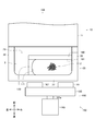
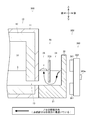
- the melting furnace 200 which is 2nd embodiment of the melting apparatus which concerns on this invention using FIG.7 and FIG.8 is demonstrated.
- the same member number is attached
- the melting furnace 200 includes a main body 10, a charging tank 20, and a stirring device 250.
- the stirrer 250 is a second embodiment of the stirrer according to the present invention.
- the stirrer 250 agitates the molten metal 3 (the molten metal 3 stored in the lower half portion of the charging chamber 23) into which the aluminum cutting waste 2 has been charged. It is an apparatus that promotes dissolution of the cutting waste 2.
- the stirring device 250 includes a moving magnetic field generator 260, a first molten metal rectifying member 270, and a second molten metal rectifying member 280.
- the moving magnetic field generator 260 is an embodiment of the moving magnetic field device according to the present invention, and ( ⁇ ) a magnetic field that moves downward along the rear side wall 22 and ( ⁇ ) upwards along the rear side wall 22. This is a device that generates a magnetic field that moves to the inside of the charging tank 20.
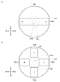
- the moving magnetic field generator 260 includes electromagnetic coils 261, 261, and a power supply device 262.
- the electromagnetic coils 261, 261... are one embodiment of a plurality of electromagnetic coils according to the present invention, and generate a magnetic field around when energized.
- the electromagnetic coils 261, 261,... are arranged in a substantially ring shape along the side wall 22 on the rear side of the charging tank 20.
- the power supply device 262 is an embodiment of the power supply device according to the present invention, and sequentially supplies power to the electromagnetic coils 261, 261, ... (in this embodiment, counterclockwise when viewed from the rear).
- the power supply device 262 sequentially supplies power to the electromagnetic coils 261, 261,... Counterclockwise as viewed from the rear, so that the electromagnetic coils 261 supplied with power are sequentially excited.
- a magnetic field that moves in a substantially ring shape (similar to the arrangement of the electromagnetic coils 261, 261,...) Along the rear side wall 22 of the charging tank 20 is generated inside the charging tank 20.
- the left half of the rear view shows a magnetic field that moves substantially downward along the rear side wall 22 of the charging tank 20
- the right half of the rear view shows a side wall 22 of the rear of the charging tank 20.
- the stirring device 250 of the melting furnace 200 sequentially supplies power to the electromagnetic coils 261, 261, and the electromagnetic coils 261, 261, which are arranged along the rear side wall 22 of the charging tank 20.
- a power supply device 262 to supply.
- the shape of the locus of the moving magnetic field is not limited to a circle as in the stirring device 150 shown in FIG. It is possible to adopt various shapes such as a linear shape and an elliptical shape according to the above.
- One embodiment of the melting method according to the present invention is a method of melting aluminum cutting waste 2 using a melting furnace 100 (see FIG. 1), and includes a charging step S1100 and a stirring step S1200.
- the charging step S1100 is a step of charging the aluminum cutting waste 2 into the molten metal 3 stored in the charging tank 20.
- the process proceeds to the stirring step S1200.
- the stirring step S1200 is a step of stirring the molten metal 3 by generating a magnetic field that moves downward along the side wall 22 on the rear side of the charging tank 20 in the charging tank 20.
- the stirring step S1200 when electric power is supplied to the motor 163 of the stirring device 150, the rotating shaft 163a, the supporting member 162 fixed to the rotating shaft 163a, and the permanent magnets 161 and 161 fixed to the supporting member 162 rotate integrally. To do.
- the permanent magnets 161 and 161 are rotated, the magnetic field that moves substantially downward along the side wall 22 on the rear side of the charging tank 20 and the rear of the charging tank 20 at a position that is a predetermined distance away from the magnetic field that moves substantially downward.
- a magnetic field that moves generally upward along the side wall 22 on the side is generated inside the charging tank 20.
- a generally downward flow of the molten metal 3 is generated in the molten metal 3.
- the aluminum cutting waste 2 charged into the molten metal 3 in the charging step S1100 moves along the flow (melt flow), sneaks into the molten metal 3 (immersed in the molten metal 3), and melts by receiving heat from the molten metal 3. .
- one embodiment of the melting method according to the present invention is based on the charging step S1100 in which the aluminum cutting waste 2 is charged into the molten metal 3 stored in the charging tank 20 and the side wall 22 on the rear side of the charging tank 20. And a stirring step S1200 for stirring the molten metal 3 by generating a magnetic field that moves downward in the charging tank 20.
- a stirring step S1200 for stirring the molten metal 3 by generating a magnetic field that moves downward in the charging tank 20 By configuring in this way, the aluminum cutting waste 2 put into the molten metal 3 is immersed in the molten metal 3 on the flow of the downward molten metal 3 (melt flow) generated by the magnetic field moving downward along the side wall 22. Therefore, it is possible to dissolve the aluminum cutting waste 2 efficiently.
- the charging tank 20 is placed at a position away from the magnetic field that moves substantially downward along the side wall 22 on the rear side of the charging tank 20 by a predetermined distance.
- a magnetic field that moves generally upward along the rear side wall 22 is generated inside the charging tank 20.
- the stirring step S1200 in the stirring step S1200, the permanent magnets 161 and 161 facing the rear side wall 22 of the charging tank 20 and the support member 162 that supports the permanent magnets 161 and 161 are used. And a motor 163 that rotationally drives the support member 162 and moves downward along the side wall 22 on the rear side of the charging tank 20 by using the moving magnetic field generator 160 disposed outside the charging tank 20. To generate a magnetic field. With this configuration, it is possible to generate a magnetic field that moves downward along the side wall 22 of the charging tank 20 with a simple and low power consumption structure.
- the apparatus for generating a magnetic field downward along the side wall of the dissolution tank in the agitation process of the dissolution method according to the present invention is not limited to the moving magnetic field generation apparatus 160 of the present embodiment.
- the first molten metal rectifying member 170 having the first molten metal rectifying surface 171 perpendicular to the rear side wall 22 and the horizontal surface of the charging tank 20 is provided. Is disposed at a position corresponding to a magnetic field that moves downward along the side wall 22 on the rear side of the charging tank 20 inside the charging tank 20.
- the first molten metal rectifying surface 171 of the first molten metal rectifying member 170 disposed in the charging tank 20 in the stirring step S1200 has a depressed central portion in plan view. Has a shape.
- the second molten metal rectifying member 180 having the second molten metal rectifying surface 181 parallel to the side wall 22 on the rear side of the charged tank 20 is added to the charged tank. 20 and disposed on the opposite side of the moving magnetic field generator 160 across the side wall 22 on the rear side of the charging tank 20.
- the process proceeds to the stirring process S1200 after the charging process S1100 is completed, but the present invention is not limited to this. That is, the charging step and the stirring step may be performed in parallel (simultaneously).
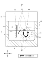
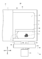
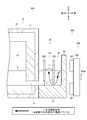
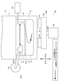
- the melting furnace 300 which is 3rd embodiment of the melting apparatus which concerns on this invention using FIGS. 11-15 is demonstrated.
- the melting furnace 300 is an apparatus that generates the molten metal 3 by melting the aluminum cutting waste 2.
- the melting furnace 300 includes a main body 10, a charging tank 20, and a stirring device 350.
- the stirrer 350 is a third embodiment of the stirrer according to the present invention.
- the stirrer 350 agitates the molten metal 3 (the molten metal 3 stored in the lower half of the charging chamber 23) into which the aluminum cutting waste 2 has been charged. It is a device that promotes dissolution of the cutting waste 2.
- the stirring device 350 includes a moving magnetic field generator 360 and a closing / floating partition member 370.
- the moving magnetic field generator 360 is an embodiment of the moving magnetic field device according to the present invention.
- ( ⁇ ) A magnetic field that moves downward along the rear side wall 22 and ( ⁇ ) an upward direction along the rear side wall 22. This is a device that generates a magnetic field that moves to the inside of the charging tank 20.
- the moving magnetic field generator 360 is disposed outside the charging tank 20 (in this embodiment, behind the charging tank 20).
- the moving magnetic field generator 360 includes permanent magnets 361 and 361, a support member 362, a motor 363 having a rotating shaft 363a, and a fixed member 364.
- the basic structure of the permanent magnets 361 and 361, the support member 362, and the motor 363 having the rotating shaft 363a are the permanent magnets 161 and 161 and the support member 162 in FIG. , And the motor 163 having the rotating shaft 163a, the description thereof will be omitted.
- the fixing member 364 is a member that fixes the motor 363 to a predetermined position with respect to the charging tank 20.
- the fixing member 364 is fixed to a structure or the like (not shown).
- the input / floating partition member 370 shown in FIGS. 11, 12 and 13 is an embodiment of the input / floating partition member according to the present invention.
- the input / floating partition member 370 is a plate-like member having at least a surface as a refractory material such as ceramics.
- the inside of the charging / floating partition member 370 may be a heat-resistant material such as metal.
- the input / floating partition member 370 is disposed inside the input tank 20 (inside the input chamber 23). More specifically, the input / floating partition member 370 is disposed at a position opposite to the moving magnetic field generator 360 across the side wall 22 on the rear side of the input tank 20.
- the left end portion of the charging / floating partition member 370 is fixed to the middle portion in the front-rear direction of the left side wall 22 of the charging tank 20, and the right end portion of the charging / floating partition member 370 is the right side of the charging tank 20.
- the side wall 22 is fixed to a midway portion in the front-rear direction.
- the charging / floating partition member 370 partitions (partitions) the space inside the charging tank 20 into two spaces of the charging / dissolving chamber 24 and the floating substance recovery chamber 25.
- the charging / dissolving chamber 24 is a space closer to the moving magnetic field generator 360 out of the two spaces partitioned by the charging / floating partition member 370.
- the charging / melting chamber 24 is a space for charging the aluminum cutting waste 2 with the molten metal 3.
- the aluminum cutting waste 2 is introduced into the molten metal 3 from the portion corresponding to the charging / melting chamber 24 in the liquid surface of the molten metal 3.
- the floating substance recovery chamber 25 is a space farther from the moving magnetic field generator 360 out of the two spaces defined by the charging / floating partition member 370, and is just between the charging / dissolving chamber 24 and the holding chamber 14 in the melting tank. It is a space (intermediate chamber) provided in the middle.
- the floating material collection chamber 25 is a space for collecting Noro 4 (see FIGS. 14 and 15) generated by melting the aluminum cutting waste 2 (dissolving by putting the aluminum cutting waste 2 into the molten metal 3). .
- Noro 4 has various foreign matters mixed in the aluminum cutting waste 2 introduced into the molten metal 3, the surface of the aluminum cutting waste 2 oxidized (oil, paint, combustible, etc.), the surface of the aluminum cutting waste 2 is Oxidized, non-metallic inclusions, or a mixture (aggregate) thereof, etc., which can float on the molten metal 3 because the density (strictly speaking, bulk density) is lower than that of the molten metal 3. .
- Noro 4 is an embodiment of the suspended matter according to the present invention.
- the upper end portion of the charging / floating partition member 370 is disposed at a position above the liquid level of the molten metal 3. Further, a gap of a predetermined size (L1 in FIG. 13) is formed between the lower end of the charging / floating partition member 370 and the bottom floor 21 of the charging tank 20, and the charging / dissolving chamber 24 and the floating substance recovery are formed.
- the chambers 25 communicate with each other in the lower part of these spaces.
- the charging / floating partition member 370 moves between the charging / dissolving chamber 24 and the floating substance recovery chamber 25 in a portion where the molten metal 3 is close to the liquid surface (portion close to the liquid surface of the molten metal 3). Regulate (the molten metal 3 cannot move between the charging / dissolving chamber 24 and the suspended matter recovery chamber 25 at a portion close to the liquid surface).
- the charging / floating partition member 370 is disposed between the charging / dissolving chamber 24 and the floating material recovery chamber 25 (the charging / floating partition member) in a portion where the molten metal 3 is far from the liquid surface (a portion closer to the bottom floor 21). Allowing movement relative to each other (through the gap between 370 and the bottom floor 21).
- the part which comprises the rear surface of the structure 11 is arrange
- the portion forming the rear surface of the structure 11 is disposed at a position farther from the moving magnetic field generator 360 than the input / floating partition member 370.
- the portion constituting the rear surface of the structure 11 is a “portion farther from the moving magnetic field generator 360 than the input / floating partition member 370 in the space inside the dissolution tank of the present embodiment”, the suspended matter recovery chamber 25 and the holding chamber 14. Is divided into two spaces.
- a communication path 15 is formed below the lower end of the portion forming the rear surface of the structure 11 (lower rear surface of the structure 11), and the suspended matter collection chamber 25 and the holding chamber 14 communicate with each other in the lower portion of these spaces.
- the suspended matter recovery chamber 25 is a space closer to the moving magnetic field generator 360 out of two spaces partitioned with the portion forming the rear surface of the structure 11 as a boundary.
- the holding chamber 14 is a space farther from the moving magnetic field generator 360 among the two spaces defined by the portion constituting the rear surface of the structure 11, and the molten metal 3 is taken out from the holding chamber 14 (recovery). ) Therefore, the holding chamber 14 corresponds to one embodiment of the molten metal recovery chamber according to the present invention, and the portion forming the rear surface of the structure 11 corresponds to one embodiment of the floating / molten metal partitioning member according to the present invention.
- the support member 362 By supplying electric power to the motor 363 of the moving magnetic field generator 360, the support member 362 (and thus the permanent magnets 361 and 361) rotates counterclockwise in the rear view (back view). Therefore, in the molten metal 3 inside the charging tank 20 (the charging / melting chamber 24 and the floating substance recovery chamber 25), a magnetic field that moves counterclockwise in the rear view is generated as in the melting furnace 100 shown in FIG. Along with the moving magnetic field, a “counterclockwise spiral flow in the rear view” is generated in the molten metal 3.
- the aluminum cutting waste 2 introduced into the liquid surface of the molten metal 3 in the charging / melting chamber 24 is wound into the molten metal 3 along the flow inside the molten metal 3.
- the aluminum cutting waste 2 caught in the molten metal 3 is melted while moving forward in the molten metal 3 in the charging / melting chamber 24 while turning counterclockwise in a rear view.
- the undissolved aluminum cutting waste 2 moves from the charging / dissolving chamber 24 to the suspended matter recovery chamber 25 through a gap between the lower end of the charging / floating partition member 370 and the bottom floor 21 of the charging tank 20. .
- the magnetic field that moves counterclockwise in the rear view generated in the molten metal 3 becomes weaker as the distance from the permanent magnets 361 and 361 increases.
- the charging / dissolving chamber 24 and the suspended matter recovery chamber 25 are partitioned by the charging / floating partition member 370 at a portion close to the liquid level of the molten metal 3, it is generated in the molten metal 3 inside the charging / melting chamber 24.
- the “counterclockwise spiral flow in the rear view” is blocked to some extent by the input / floating partition member 370.
- the “counterclockwise spiral flow in the rear view” generated in the molten metal 3 in the floating substance recovery chamber 25 is generated in the “counterclockwise in the rear view” generated in the molten metal 3 in the charging / dissolving chamber 24. Although it is weaker than the “spiral flow”, it is spiral to a certain extent, but the flow is generally gentle forward. Moreover, since the density of the undissolved aluminum cutting waste 2 and the density of the molten metal 3 are substantially the same, the buoyancy which the undissolved aluminum cutting waste 2 receives from the molten metal 3 and the gravity acting on the undissolved aluminum cutting waste 2 ( The weight is almost balanced.
- the undissolved aluminum cutting waste 2 that has moved into the suspended matter recovery chamber 25 through the gap between the lower end of the input / floating partition member 370 and the bottom floor 21 of the input tank 20 is greatly increased by buoyancy. Without being lifted upward, it will be dissolved while slowly moving forward.
- the undissolved aluminum cutting waste 2 moves from the suspended matter recovery chamber 25 to the holding chamber 14 through the communication path 15. Since the holding chamber 14 is further away from the permanent magnets 361 and 361 than the suspended matter collection chamber 25, the molten metal 3 inside the charging / dissolving chamber 24 has a “counterclockwise spiral flow in the rear view”. It hardly occurs. Of the aluminum cutting scraps 2 put on the liquid surface of the molten metal 3 in the charging / melting chamber 24, those that have moved to the holding chamber 14 without being melted receive heat from the molten metal 3 inside the holding chamber 14, Will be dissolved.
- the aluminum cutting waste 2 charged on the surface of the molten metal 3 in the charging / dissolving chamber 24 is generated in the molten metal 3 by the moving magnetic field generator 360 "a spiral flow counterclockwise in a rear view. It is dissolved in the process of moving along. Further, the aluminum cutting waste 2 moves in the order of the liquid level of the molten metal 3 in the charging / melting chamber 24 ⁇ the lower part of the molten metal 3 in the charging / melting chamber 24 ⁇ the lower part of the molten metal 3 in the floating substance recovery chamber 25 ⁇ It does not move to the vicinity of the liquid level of the molten metal 3 in the suspended matter recovery chamber 25.
- Noro 4 generated when the aluminum cutting waste 2 is introduced into the liquid surface of the molten metal 3 in the charging / melting chamber 24 is wound into the molten metal 3 along the flow inside the molten metal 3.
- the roll 4 entrained in the molten metal 3 moves forward in the molten metal 3 in the charging / melting chamber 24 while turning counterclockwise in a rear view.
- Noro 4 moves from the charging / dissolving chamber 24 to the floating substance recovery chamber 25 through a gap between the lower end of the charging / floating partition member 370 and the bottom floor 21 of the charging tank 20.
- the buoyancy that the Noro 4 receives from the molten metal 3 is greater than the gravity (self-weight) acting on the Noro 4. Therefore, the noro 4 that has moved into the floating substance collection chamber 25 through the gap between the lower end portion of the charging / floating partition member 370 and the bottom floor 21 of the charging tank 20 is located inside the floating substance collection chamber 25. It deviates from the flow generated in the molten metal 3 (although it is spiral to some extent, the flow is generally gently forward), and floats to the right half of the liquid level of the molten metal 3 in the suspended matter recovery chamber 25 by buoyancy.
- the slag 4 that has floated to the right half of the liquid level of the molten metal 3 in the floating substance recovery chamber 25 gently floats along the flow generated inside the molten metal 3 in the floating substance recovery chamber 25 while floating on the liquid level of the molten metal 3. It moves to the left end of the liquid level of the molten metal 3 in the suspended matter recovery chamber 25 and stays there (see FIG. 14).
- the noro 4 generated when the aluminum cutting waste 2 is introduced into the liquid surface of the molten metal 3 in the charging / dissolving chamber 24 is separated from the aluminum cutting waste 2, and a specific position in the melting tank (this embodiment). Then, “the left end portion of the liquid level of the molten metal 3 in the suspended matter recovery chamber 25”).
- the collected Noro 4 is collected manually or automatically (taken out).
- the method for manually collecting the Noro 4 there is a method in which an operator scrapes (scraps) using a tool such as a handle.
- the method for automatically collecting the Noro 4 there is a method using a device that scoops the Noro 4 from the vicinity of the liquid surface of the molten metal 3.
- the stirring device 350 is a stirring device that promotes the melting of the aluminum cutting waste 2 by stirring the molten metal 3 into which the aluminum cutting waste 2 is charged, and is provided outside the melting tank that stores the molten metal 3
- a magnetic field that is arranged outside the charging tank 20 and moves downward along the side wall of the melting tank (in this embodiment, the side wall 22 on the rear side of the charging tank 20) is generated inside the melting tank.
- the moving magnetic field generator 360 and the inside of the melting tank (in this embodiment, the inside of the charging tank 20) are arranged in two spaces (the charging / dissolving chamber 24 and A space that is closer to the moving magnetic field generator 360 out of the two spaces partitioned by the input / floating partition member 370 (this embodiment).
- the space in the latter half of the charging tank 20 is a charging / melting chamber 24 that is a space for charging the aluminum cutting waste 2 into the molten metal 3 in the melting tank, and is far from the moving magnetic field generator 360 of the two spaces.
- This space (in this embodiment, the space in the first half of the charging tank 20) is a floating material collection chamber 25 that is a space for collecting the noro 4 generated by melting the aluminum cutting waste 2.
- the prior art (A) is provided in an open well portion of a melting furnace (a portion of the melting tank whose upper surface is open), and a rotating blade that rotates mainly about an axis in the vertical direction, A casing for covering, and a chute for introducing aluminum scrap into a gap between the rotary blade and the inner peripheral surface of the casing are provided.
- An opening through which the molten metal can be sucked is formed on the lower surface of the casing, an opening through which the molten metal can flow out is formed on the side surface of the casing, and a chute is connected to the upper surface of the casing.
- the aluminum scrap thrown into the chute slides down in the gap between the rotary blade and the inner peripheral surface of the casing, and is stirred by the rotary blade while being immersed in the molten metal. As a result, the aluminum scrap moves from the opening formed on the side surface of the casing to the inside of the melting furnace while being melted.
- a method for solving such a problem a method in which an open / close door is provided between the open well portion and the main furnace and a cycle including the following three steps (a1) to (a3) is repeated.
- A1 The aluminum door is melted by closing the open / close door and rotating the rotary blade.
- A2) Collect the floating matter floating on the surface of the molten metal in the open well portion.
- A3) Open the open / close door and mix the molten metal in the open well portion and the molten metal inside the main furnace.
- the above method cannot simultaneously melt the aluminum scrap and heat the molten metal in the furnace (becomes a batch operation), and lowers the temperature of the molten metal by putting the aluminum scrap into the molten metal in the open well section. Therefore, productivity (dissolution amount per unit time) is reduced because of a decrease in dissolution rate. Further, when the open / close door is opened, the heat inside the furnace is released to the outside, which causes a problem that the energy cost increases. In addition, if the door is made thick to prevent the heat of the main furnace from escaping in order to improve thermal efficiency, the door will become heavier by that amount, resulting in larger equipment, increased equipment costs, and There is a problem of increased energy consumption required for opening and closing.
- step (a2) floating substances are spread and distributed over the entire open well portion, so that the operation of collecting the floating substances becomes complicated (required for the operation of collecting the floating substances). Time and effort), which also reduces productivity.
- the tip tool (bar-shaped member) is immersed in the melt from the open well portion of the melting furnace, and the tip tool is moved back and forth and up and down (locomotion motion) to stir the melt.
- the tip tool immerses the molten material in the molten metal while finely crushing the suspended material and finely pulverizing the suspended material.
- concentration of floating substances as foreign matter in the molten metal increases.
- the same method as that described in the description of the prior art (A) can be considered.
- the same problem as in the prior art (A) (productivity reduction, device) Increase in equipment cost, increase in equipment cost, increase in energy consumption associated with opening and closing of the door, and complexity of floating substance collection work.
- the stirring device 350 can collect and collect the slot 4 at a specific position of the suspended matter collection chamber 25 (the left end portion of the liquid level of the molten metal 3 in the suspended matter collection chamber 25). Is easy (there is no need to recover Noro 4 over the entire surface of the molten metal 3 in the charging tank 20). Further, the stirring device 350 can prevent the Noro 4 from being mixed into the molten metal inside the holding chamber 14, and contributes to improving the quality of the molten metal inside the holding chamber 14. Further, the stirring device 350 does not need to be provided with an openable / closable door that partitions the charging tank 20 (open well portion) and the main body 10 (main furnace), and can be easily installed in an existing melting furnace.
- the stirring device 350 includes an operation of charging the aluminum cutting waste 2 into the molten metal 3 to melt it (stirring the molten metal 3), an operation of recovering the noro 4, and the molten metal in the charging tank 20 and the interior of the main body 10. Since the operations of mixing the molten metal (melted inside the holding chamber 14) and the molten metal (the charging / dissolving chamber 24, the floating substance recovery chamber 25 and the holding chamber 14) are performed in parallel, these operations are performed in parallel. This can be done in a continuous manner, and as a result, continuous operation contributes to the improvement of productivity.
- the input / floating partition member 370 is a plate-like member, and the plate surface of the input / floating partition member 370 is in the axial direction of the rotating shaft 363 a of the motor 363 of the moving magnetic field generator 360, that is, the moving magnetic field generator 360.
- the present invention is not limited to this. In other words, if it is possible to collect Noro 4 in the suspended matter collection chamber 25, the plate surface of the suspended matter collection chamber 25 is in the macro traveling direction of the flow of the spiral molten metal 3 generated by the moving magnetic field generator 360. However, it may be slightly inclined from the vertical state.
- the portion forming the rear surface of the structure 11 corresponds to an embodiment of the floating / molten metal partitioning member according to the present invention, but the present invention is not limited to this.
- it is disposed inside the melting tank (in FIG. 16 and FIG. 17, inside the charging tank 20) and at a position farther from the moving magnetic field generator 360 than the charging / floating partition member 370. It is good also as a structure which comprises the floating / molten metal partition member 380.
- FIG. 16 and FIG. 17 it is disposed inside the melting tank (in FIG. 16 and FIG. 17, inside the charging tank 20) and at a position farther from the moving magnetic field generator 360 than the charging / floating partition member 370. It is good also as a structure which comprises the floating / molten metal partition member 380.
- the floating / molten metal partition member 380 is a member that divides a portion farther from the moving magnetic field generator 360 than the charging / floating partition member 370 in the space inside the melting tank into two spaces communicating with each other in the lower part.
- the suspended matter recovery chamber 25 is a space closer to the moving magnetic field generator 360 out of the two spaces partitioned by the floating / molten metal partition member 380.
- the holding chamber 14 is a space farther from the moving magnetic field generator 360 out of the two spaces partitioned by the floating / melt partition member 380, and is a space for recovering the melt 3 from the melting tank. Also serves as a collection room.
- a combination of the holding chamber 14 and the portion farther from the moving magnetic field generator 360 than the floating / molten partition member 380 in the charging tank 20 is the molten metal recovery chamber.
- the floating / molten partition member 380 shown in FIGS. 16 and 17 is a plate-like member having at least a surface made of a refractory material such as ceramics, like the charging / floating partition member 370.
- the gap L1 between the bottom floor 21 of the 20 and the gap L3 (see FIG. 17) between the lower end portion of the floating / molten metal partitioning member 380 and the bottom floor 21 of the charging tank 20 include various elements shown below. Therefore, it is desirable to set the size appropriately. That is, from the viewpoint of efficiently recovering the noro 4 to the suspended matter recovery chamber 25 by preventing the noro 4 from moving to the holding chamber 14, the gap L1 and the height L2 (or the gap L1 and the gap L3) are set as much as possible.
- the temperature of the molten metal 3 is kept constant by facilitating the movement of the molten metal 3 between the charging / dissolving chamber 24 and the suspended matter recovery chamber 25 and between the suspended matter recovery chamber 25 and the holding chamber 14. From the viewpoint of preventing the undissolved aluminum cutting waste 2 from being caught on the moving path between the charging / dissolving chamber 24 and the floating substance recovery chamber 25 or the floating substance recovery chamber 25 and the holding chamber 14. It is desirable to set L1 and height L2 (or gap L1 and gap L3) large.
- the clearance L1 (and The gap L3) may be changed (adjustable).
- the floating / floating partition member 370 is an L-shaped (plate-shaped) member made up of a first plate member 371 and a second plate member 372, so that the suspended matter collection chamber 25 is made into the main chamber 25 a and Noro 4 formed in an L shape in a plan view composed of a sub chamber 25b connected to one end of the main chamber 25a and floated on the liquid surface of the molten metal 3 in the main chamber 25a of the suspended matter recovery chamber 25 is near the liquid surface of the molten metal 3.
- the main chamber 25a is moved from the right to the left on the flow, and gathers in the sub chamber 25b bent backward (the flow of the liquid surface of the molten metal 3 in the main chamber 25a is the other end of the main chamber 25a.
- the stirring device 350 may include a flux injection device 391 and a suspended matter recovery device 392.
- the flux injection device 391 is a device that supplies flux to the molten metal 3.
- flux refers to a substance that generates Noro 4 by acting on impurities inside the molten metal 3.
- the flux injection device 391 supplies the flux to the right end of the liquid surface of the molten metal 3 in the suspended matter recovery chamber 25, thereby separating and removing the float 4 floating in the molten metal 3. (Improve the concentration of impurities and foreign matter)
- the suspended matter collection device 392 is a device that collects the float 4 floating on the liquid surface of the molten metal 3.
- the suspended matter collection device 392 includes a jig 392 a that scoops the roll 4, and the jig 392 a is the left end of the liquid level of the molten metal 3 in the float collection chamber 25, that is, It is arranged at the gathering position.
- the suspended matter recovery device 392 does not need to scan the entire liquid surface of the molten metal 3 in the charging tank 20 and scoop out the noro 4.
- the scrap 4 can be efficiently recovered simply by scooping it off at the left end of the liquid level of the molten metal 3 in the material recovery chamber 25, and the structure of the suspended matter recovery device 392 can be simplified. Further, since the suspended matter recovery device 392 does not interfere with other devices constituting the stirring device 350 or other members constituting the melting furnace 300 when performing the work of collecting the waste 4, the waste 4 is recovered.
- the work to be performed can be performed continuously (simultaneously with other work), which contributes to the improvement of the quality of the molten metal 3 and the labor saving of the work of recovering the noro 4.
- a melting furnace 400 which is the fourth embodiment of the melting apparatus according to the present invention and a method of melting the aluminum cutting waste 2 using the melting furnace 400 will be described with reference to FIGS.
- the melting furnace 400 is a device that generates the molten metal 3 by melting the aluminum cutting waste 2, and includes a main body 10, a charging tank 20, a moving magnetic field generator 460, and a moving magnetic field generator 470.
- the main body 10 maintains the temperature of the molten metal 3 at a temperature higher than the solidification temperature.
- the main body 10 includes a structure 11, a refractory / heat insulating material 12, and a burner 13.
- the structure 11 is an embodiment of the outer plate according to the present invention, and is a substantially rectangular parallelepiped box-like member in which plate-like members (for example, steel plates) made of a metal material are combined.
- the refractory / heat insulating material 12 is a member made of ceramics or the like, and is fixed to the inner peripheral surface of the structure 11 (the inner plate surface of the plate-like member constituting the structure 11), thereby the inner periphery of the structure 11. Cover the surface.
- a holding chamber 14 is formed inside the structure 11 as a space surrounded by the fireproof and heat insulating material 12, and a communication path 15 is formed at the lower part of the rear surface of the structure 11.
- the molten metal 3 is stored in the lower half of the holding chamber 14.
- the burner 13 is provided in the upper part of the inner peripheral surface in front of the structure 11 and raises the temperature of the air inside the holding chamber 14 and eventually the molten metal 3 (the molten metal 3 in contact with the air) stored in the lower half of the holding chamber 14. To do.
- the charging tank 20 is a portion into which the aluminum cutting waste 2 is charged in the melting furnace 400.
- the charging tank 20 is fixed to the rear end portion of the main body 10.
- the charging tank 20 includes a bottom floor 21 and side walls 22.
- the bottom floor 21 is a substantially rectangular plate-like portion in plan view that extends rearward from the rear end of the structure 11 in the charging tank 20.
- the bottom floor 21 of this embodiment includes an outer plate 21a and a refractory material 21b.
- the outer plate 21a is an embodiment of the outer plate according to the present invention, and is a member that forms the outer half of the bottom floor 21 (the lower half in the present embodiment).
- the outer plate 21a of the present embodiment is a plate-like member (for example, a steel plate) made of a metal material.
- the refractory material 21b is a member made of ceramics or the like, and covers the inner plate surface of the outer plate 21a by being fixed to the inner plate surface of the outer plate 21a (in this embodiment, the upper plate surface).
- the side wall 22 is a plate-like portion erected along the left end portion, the rear end portion, and the right end portion of the bottom floor 21 in the charging tank 20.
- the left front end and the right front end of the side wall 22 extend to the rear left end and the rear right end of the structure 11, respectively.
- the side wall 22 of the present embodiment includes an outer plate 22a and a refractory material 22b.
- the outer plate 22a is an embodiment of the outer plate according to the present invention, and the outer half of the side wall 22 (the latter half in the case of the portion of the side wall 22 erected along the rear end of the bottom floor 21). It is the member which comprises.
- the outer plate 22a of the present embodiment is a plate-like member (for example, a steel plate) made of a metal material.
- the refractory material 22b is a member made of ceramics or the like, and in the case of the outer plate 22a corresponding to the plate surface inside the outer plate 22a (the portion of the side wall 22 erected along the rear end of the bottom floor 21) The plate surface on the inner side of the outer plate 22a is covered.
- An input chamber 23 is formed as a space surrounded by the bottom floor 21, the side wall 22, and the rear surface of the structure 11 in the input tank 20.
- the molten metal 3 is stored in the lower half of the charging chamber 23.
- the holding chamber 14 and the charging chamber 23 are communicated with each other through a communication path 15, and the molten metal 3 can move between the holding chamber 14 and the charging chamber 23 through the communication path 15.
- the upper surface of the charging tank 20 is open, and the aluminum cutting waste 2 is charged into the charging chamber 23 through the opening.
- the aluminum cutting waste 2 charged into the charging chamber 23 is heated in contact with the molten metal 3 stored in the lower half of the charging chamber 23 and melts when the temperature reaches the melting point or higher.
- the inner peripheral surface is the refractory / heat insulating material 12.
- Both “covered structure 11” and “input tank 20” correspond to an embodiment of the dissolution tank according to the present invention.
- the moving magnetic field generator 460 is an embodiment of the moving magnetic field generator according to the present invention, and generates a magnetic field that moves along the rear side wall 22 (rear outer plate 22a) inside the charging tank 20.
- the molten metal 3 into which the aluminum cutting waste 2 has been charged (the molten metal 3 stored in the lower half of the charging chamber 23) is agitated, and consequently the melting of the aluminum cutting waste 2 is promoted.
- the moving magnetic field generator 460 is disposed outside the charging tank 20, more specifically behind the charging tank 20.
- the moving magnetic field generator 460 includes permanent magnets 461a and 461b, a support member 462, a motor 463, and a fixed member 464.
- the permanent magnets 461a and 461b are one embodiment of the permanent magnet according to the present invention, and face the rear side wall 22 (the plate surface on the outer side of the rear outer plate 22a) as shown in FIGS. .
- the permanent magnets 461a and 461b are composed of neodymium magnets.
- the moving magnetic field generator 460 includes two permanent magnets 461a and 461b.
- the present invention is not limited to this, and the number of permanent magnets included in the moving magnetic field generator according to the present invention is as follows. It may be singular or plural.
- the support member 462 is an embodiment of the support member according to the present invention, and supports the permanent magnets 461a and 461b.
- the support member 462 of this embodiment is a substantially disk-shaped member.
- the permanent magnets 461a and 461b are fixed to the board surface of the support member 462 facing the rear side wall 22.
- the motor 463 is an embodiment of the motor according to the present invention, and rotationally drives the support member 462 and eventually the permanent magnets 461a and 461b fixed to the support member 462.
- a rotation shaft 463 a of the motor 463 is an embodiment of the rotation shaft according to the present invention, and is fixed to the support member 462.
- the axis of the rotation shaft 463a and the center line of the support member 462 fixed to the rotation shaft 463a (a line passing through the center of the pair of board surfaces of the support member 462) are in a straight line.
- the motor 463 of the present embodiment is an electric motor
- the motor according to the present invention is not limited to this, and may be a motor (for example, a hydraulic motor, a pneumatic motor, etc.) that is driven to rotate by fluid pressure. good.
- the fixing member 464 is a member that fixes the motor 463 at a position behind the charging tank 20.
- the fixing member 464 is fixed to a structure or the like (not shown).
- the rotation shaft 463a of the motor 463 is perpendicular to the rear side wall 22 (the plate surface outside the rear outer plate 22a).
- the board surface of the support member 462 is parallel to the rear side wall 22 (the outer plate surface of the rear outer plate 22a).
- the rotation shaft 463a, the support member 462 fixed to the rotation shaft 463a, and the permanent magnets 461a and 461b fixed to the support member 462 are integrally rotated around the rotation shaft 463a.
- the permanent magnets 461a and 461b rotate counterclockwise in the rear view.
- a magnetic field that moves generally downward along the rear side wall 22 is generated in the charging tank 20 corresponding to the portion of the rear side wall 22 that faces the left half of the support member 462. It moves substantially upward along the rear side wall 22 inside the charging tank 20 corresponding to a portion facing the right half of the support member 462 (ie, a position away from the magnetic field moving downward by a predetermined distance).
- a magnetic field is generated.
- a magnetic field that moves counterclockwise in a rear view is generated in the portion of the charging tank 20 that faces the permanent magnets 461a and 461b.
- a flow (melt flow) of the molten metal 3 that circulates around an axis (in this embodiment, the rotation shaft 463a of the motor 463) that is substantially parallel to the liquid level of the molten metal 3 is generated in the molten metal 3.
- the aluminum cutting waste 2 moves on the flow of the molten metal 3 (molten metal flow), and the flow of the molten metal 3 generally downward (the molten metal) In the position where the (flow) is generated, it enters the inside of the molten metal 3 (is immersed in the molten metal 3) and receives heat from the molten metal 3 to melt.
- the molten metal 3 in the vicinity of the position where the aluminum cutting waste 2 is melted decreases due to melting of the aluminum cutting waste 2, the molten metal 3 is agitated by the flow of the molten metal 3 (melt flow).
- the temperature of 3 is kept substantially uniform.
- the moving magnetic field generator 470 agitates the molten metal 3 stored in the lower half of the holding chamber 14 by generating a magnetic field that moves along the plate-like member forming the lower surface of the structure 11 inside the main body 10.
- the temperature of the molten metal 3 is made uniform.
- the moving magnetic field generator 470 is disposed outside the main body 10, more specifically, below the main body 10.
- the moving magnetic field generator 470 includes permanent magnets 471a and 471b, a support member 472, a motor 473, and a fixed member 474.
- the permanent magnets 471a and 471b are opposed to a plate-like member forming the lower surface of the structure 11.
- the permanent magnets 471a and 471b are composed of neodymium magnets.
- the support member 472 supports the permanent magnets 471a and 471b.
- the support member 472 of this embodiment is a substantially disk-shaped member.
- the permanent magnets 471a and 471b are fixed to the surface of the support member 462 facing the plate-like member forming the lower surface of the structure 11.
- the motor 473 rotates the permanent magnets 471a and 471b fixed to the support member 472 and eventually the support member 472.
- a rotation shaft 473 a of the motor 473 is fixed to the support member 472.
- the axis of the rotation shaft 473a and the center line of the support member 472 fixed to the rotation shaft 473a are in a straight line.
- the fixing member 474 is a member that fixes the motor 473 at a position below the plate-like member that forms the lower surface of the structure 11.
- the fixing member 474 is fixed to a structure or the like (not shown).
- the rotation shaft 473 a of the motor 473 is perpendicular to the lower plate surface of the plate-like member that forms the lower surface of the structure 11.
- the board surface of the support member 472 is parallel to the lower plate surface of the plate-like member that forms the lower surface of the structure 11.
- the rotating shaft 473a, the supporting member 472 fixed to the rotating shaft 473a, and the permanent magnets 471a and 471b fixed to the supporting member 472 are integrally driven around the rotating shaft 473a.
- the permanent magnets 471a and 471b rotate counterclockwise when viewed from the bottom).
- a magnetic field that moves counterclockwise as viewed from the bottom is generated in the portion of the main body 10 that faces the permanent magnets 471a and 471b.
- a flow (melt flow) of the spiral molten metal 3 that circulates around the rotation shaft 473a) of the motor 473 is generated. Therefore, the molten metal 3 is agitated inside the main body 10 (holding chamber 14), and the portion heated by the burner 13 and the other portion of the molten metal 3 are mixed, so that the temperature of the molten metal 3 becomes substantially uniform.
- the permanent magnets 461 a and 461 b are arranged on the surface of the support member 462 facing the rear side wall 22 (the outer surface of the rear outer plate 22 a) with the center of the surface of the plate interposed therebetween. It is fixed at a position equidistant from the center of the board surface.
- the front surface of the permanent magnet 461a (the surface facing the outer plate surface of the rear outer plate 22a) is magnetized to the N pole, and is in contact with the rear surface of the permanent magnet 461a (the plate surface of the support member 462). The surface is magnetized on the S pole.
- the front surface of the permanent magnet 461b (the surface facing the outer plate surface of the rear outer plate 22a) is magnetized to the S pole, and the rear surface of the permanent magnet 461b (the surface in contact with the disk surface of the support member 462). Magnetized in the N pole. Therefore, the N pole of the permanent magnet 461a and the S pole of the permanent magnet 461b are positions that are 180 ° out of phase with each other about the rotation shaft 463a when viewed from the axial direction of the rotation shaft 463a (the front-rear direction in this embodiment). Placed in.
- the rear outer plate 22a is a plate-like member made of a simple metal material
- the rear outer plate is rotated when the support member 462 on which the permanent magnets 461a and 461b are arranged is rotating.
- An induced current C flows through 22a in a direction parallel to the plate surface of the outer plate 22a and perpendicular to the line 30 connecting the permanent magnets 461a and 461b, and the outer plate 22a generates heat due to the electric resistance of the outer plate 22a. Temperature rises. Further, as shown in FIGS.
- the direction in which the induced current C flows changes with the rotation of the support member 462 on which the permanent magnets 461a and 461b are arranged, but the rear outer plate 22a .
- the induced current C always flows at a position between the permanent magnets 461a and 461b, that is, a position facing the rotation center (rotary shaft 463a) of the support member 462 (hereinafter referred to as “the center position of the outer plate 22a”). It becomes. Accordingly, the central position of the outer plate 22a generates a larger amount of heat than its surroundings, and the temperature at the central position of the outer plate 22a is higher than its surrounding temperature.
- the portions facing the permanent magnets 461a and 461b on the outer plate surface of the rear outer plate 22a (more precisely, the outer plate of the rear outer plate 22a).
- the resistance groove 481 and the sub-resistance groove 482. By forming 483, 484 and 485, as shown in FIG. 34, “the heat generation (abnormal overheating) of the rear outer plate 22a caused by the induced current C always flowing (concentrating) at the center position of the outer plate 22a. Is reduced.
- the resistance groove 481 is an embodiment of the resistance band according to the present invention.
- the resistance groove 481 of the present embodiment is a groove that penetrates from the inner plate surface (front plate surface) of the rear outer plate 22a to the outer plate surface (rear plate surface). Since the portion where the resistance groove 481 is formed in the outer plate 22a is substantially hollow, the resistance groove 481 is usually filled with air. Therefore, the electrical resistance of the resistance groove 481 (strictly speaking, the portion where the resistance groove 481 is formed in the outer plate 22a) is equal to the other portion of the outer plate 22a made of a metal material (the resistance groove 481 and the auxiliary groove in the outer plate 22a). It is larger than the electric resistance of the portion where the resistance grooves 482, 483, 484, and 485 are not formed.
- the middle portion of the resistance groove 481 (in this embodiment, the center portion of the resistance groove 481) is disposed at the center position of the outer plate 22a. Further, both end portions of the resistance groove 481 are located away from the center position of the outer plate 22a (in this embodiment, the permanent magnet 461a. The left and right ends of the portion surrounded by the rotation locus of 461b. Therefore, in this embodiment, the resistance groove 481 has a shape extending right and left through the center position of the outer plate 22a. Further, as shown in FIG. 25, the resistance groove 481 has a shape without a cut in the middle, that is, a shape connected from the left end portion of the resistance groove 481 to the right end portion through the center portion.
- the auxiliary resistance grooves 482, 483, 484, and 485 are one embodiment of the auxiliary resistance band according to the present invention.
- the auxiliary resistance grooves 482, 483, 484, and 485 of this embodiment are all grooves that penetrate from the inner plate surface (front plate surface) of the rear outer plate 22a to the outer plate surface (rear plate surface). It is. Since the portion of the outer plate 22a where the resistance groove 481 is formed is substantially hollow, the auxiliary resistance grooves 482, 483, 484, and 485 are usually filled with air.
- the electrical resistance of the auxiliary resistance grooves 482, 483, 484, and 485 (strictly speaking, the portion where the auxiliary resistance grooves 482, 483, 484, and 485 are formed in the outer plate 22a) is the outer plate 22a made of a metal material.
- the electric resistance of the other part (the part where the resistance groove 481 and the auxiliary resistance grooves 482, 483, 484, and 485 are not formed in the outer plate 22a) is larger.
- the auxiliary resistance groove 482 is disposed at a position above the resistance groove 481 by a predetermined distance in a portion of the rear outer plate 22a facing the permanent magnets 461a and 461b.
- the auxiliary resistance groove 483 is disposed at a position that is a predetermined distance above the auxiliary resistance groove 482 in the portion of the rear outer plate 22a that faces the permanent magnets 461a and 461b.
- the auxiliary resistance groove 484 is disposed at a position below the resistance groove 481 by a predetermined distance in a portion facing the permanent magnets 461a and 461b in the rear outer plate 22a.
- the auxiliary resistance groove 485 is disposed at a position below the auxiliary resistance groove 484 by a predetermined distance in a portion facing the permanent magnets 461a and 461b in the rear outer plate 22a.
- the auxiliary resistance grooves 482, 483, 484, and 485 all have a shape that is elongated to the left and right, and the auxiliary resistance groove 482, the auxiliary resistance groove 483, the auxiliary resistance groove 484, and the auxiliary resistance groove 485 are all. It is separated from the resistance groove 481 (the resistance groove 481, the sub resistance groove 482, the sub resistance groove 483, the sub resistance groove 484 and the sub resistance groove 485 are not connected to each other).
- the portion of the rear outer plate 22a that faces the permanent magnets 461a and 461b is formed by the resistance groove 481 and the auxiliary resistance grooves 482, 483, 484, and 485 as “the portion that is above the auxiliary resistance groove 483” and “the auxiliary resistance groove. 483 and the portion sandwiched between the auxiliary resistance groove 482, “the portion sandwiched between the secondary resistance groove 482 and the resistance groove 481,” “the portion sandwiched between the resistance groove 481 and the secondary resistance groove 484”, “the secondary resistance groove 484 and the secondary resistance. It is divided into a total of six parts, “parts sandwiched by the grooves 485” and “parts below the auxiliary resistance grooves 485”.
- the resistance groove 481 and the auxiliary resistance grooves 482, 483, 484, and 485 have an electric resistance larger than that of the metal material constituting the rear outer plate 22 a, it is impeded that current flows across the six adjacent portions. (Or the current value flowing across adjacent portions is reduced). Accordingly, the support member 462 on which the permanent magnets 461a and 461b are arranged rotates while facing the outer plate 22a on the rear side where the resistance grooves 481 and the auxiliary resistance grooves 482, 483, 484 and 485 are formed as shown in FIG. When the induced currents C, C,...
- the induced current C has the current value of each induced current C. This is smaller than the case where the portion surrounded by the rotation trajectory of the permanent magnets 461a and 461b flows continuously from one end side to the other end side through the center position of the outer plate 22a (see FIG. 34).
- the resistance groove 481 and the auxiliary resistance grooves 482, 483, 484, and 485 are partitioned by the resistance groove 481 and the auxiliary resistance grooves 482, 483, 484, and 485 in order to prevent current from flowing across adjacent portions.
- the induced current C which is induced for each part and flows toward the center position of the outer plate 22a, changes its direction when it reaches the vicinity of the resistance groove 481 and the auxiliary resistance grooves 482, 483, 484, and 485, and the resistance It flows along the longitudinal direction of the groove 481 and the auxiliary resistance grooves 482, 483, 484, and 485 (in this embodiment, the left-right direction). Therefore, it is avoided that the induced current C is concentrated at the center position of the outer plate 22a, and heat generation at the center position of the outer plate 22a is reduced.
- Grooves are completely formed in the portions facing the permanent magnets 461a and 461b on the outer plate surface of the outer plate 22a shown in FIG. 26A (portions surrounded by the two-dot chain line in FIG. 26A). It has not been.
- a plurality of grooves 486 are provided in the portion of the outer plate surface of the outer plate 22a shown in FIG. 26B facing the permanent magnets 461a and 461b (the portion surrounded by the two-dot chain line in FIG. 26B).
- a plurality of grooves 486 are provided.
- the plurality of grooves 486, 486,... Are arranged at predetermined intervals on the circumference of a circle centered on the center position of the outer plate 22a.
- the plurality of grooves 486, 486,... Are independent from each other (adjacent grooves 486, 486 are not connected).
- the plurality of grooves 487, 487,... are centered on the center position of the outer plate 22a and have a predetermined interval on the circumference of a circle having a diameter larger than the circle corresponding to the plurality of grooves 486, 486,. Is opened and placed.
- the plurality of grooves 487, 487,... Are independent from each other.
- the plurality of grooves 488, 488,... are centered on the center position of the outer plate 22a and have a predetermined interval on the circumference of a circle having a diameter larger than the circle corresponding to the plurality of grooves 487, 487,. Is opened and placed.
- the plurality of grooves 488, 488,... Are independent of each other.
- the plurality of grooves 489, 489,... are independent of each other.
- two grooves 490 are formed in a portion facing the permanent magnets 461a and 461b on the outer plate surface of the outer plate 22a (portion surrounded by a two-dot chain line in FIG. 26 (c)).
- -491 is formed.
- the two grooves 490 and 491 are grooves extending in the left-right direction, and are arranged at a predetermined interval across the center position of the outer plate 22a.
- Sub resistance grooves 482, 483, 484, and 485 are formed.
- the resistance groove 481 and the auxiliary resistance grooves 482, 483, 484, and 485 shown in (e) of FIG. 26 correspond to the melting furnace 400 (fourth embodiment of the melting apparatus according to the present invention) shown in FIGS. Is.
- FIG. 26 correspond to “comparative example (not one embodiment of the present invention)”.
- (D) and (e) of FIG. 26 correspond to “one embodiment of the present invention”.
- the outer plate 22a of the charging tank 20 in the melting furnace 400 shown in FIGS. 20 to 25 is sequentially replaced with the outer plate 22a shown in FIGS. 26 (a) to (e), and the aluminum cutting waste 2 is melted for each.
- the temperature of the outer plate 22a was measured.
- a total of five locations from (a) and (e in FIG. 26) from the center position of the outer plate 22a shown in FIGS. 26 (a) and 26 (e) to the upper end of the portion facing the permanent magnets 461a and 461b.
- the temperature of each outer plate 22a was measured by installing a temperature sensor (thermocouple) at (i) to (v)).
- a temperature sensor thermoelectric is provided at the center position of the outer plate 22a shown in FIGS. 26B, 26C, and 26D (see (i) in FIGS. 26B, 26C, and 26D).
- the temperature of each outer plate 22a was measured by installing a pair.
- FIG. 27 shows the rising temperature of the center position of the outer plate 22a from (a) to (e) of FIG.
- the “rising temperature at the center position of the outer plate 22a” is the temperature at the center position of the outer plate 22a at the start of measurement (when the rotation of the support member 462 where the permanent magnets 461a and 461b are started).
- the difference ( T2 ⁇ T1) between the measured value (T1) and the measured value (T2) of the temperature at the center position of the outer plate 22a when the temperature is saturated (when the temperature of the outer plate 22a becomes constant).
- FIG. 27 the rising temperature at the center position of the outer plate 22a in FIGS. 26 (d) and (e) corresponding to one embodiment of the present invention is shown in FIG. 26 (a) corresponding to the comparative example. It is smaller than the rising temperature at the center position of the outer plate 22a in (b) and (c). Therefore, it can be seen that the resistance groove 481, and the combination of the resistance groove 481 and the auxiliary resistance grooves 482, 483, 484, and 485 contribute to reducing the temperature rise at the center position of the outer plate 22a.
- the rising temperature at the center position of the outer plate 22a in FIG. 26B is slightly lower than the rising temperature at the center position of the outer plate 22a in FIG. Therefore, it can be seen that the temperature rise at the center position of the outer plate 22a can be slightly reduced even with a groove (resistance band) having a mode different from that of the resistance groove 481.
- the grooves 490 and 491 substantially correspond to the resistance groove 481 in which the groove corresponding to the center position of the outer plate 22a is omitted (the resistance groove 481 is divided into two in the middle). .
- the grooves 490 and 491 not only the induced current flowing straight toward the center position of the outer plate 22 a but also the induced current flowing in a position away from the induced current has a direction along the grooves 490 and 491.
- the middle portion of the resistance groove 481 is disposed at the center position of the outer plate 22a. It can also be seen that the fact that the resistance groove 481 is not cut halfway (not divided) is effective in reducing the temperature rise at the center position of the outer plate 22a.
- the rising temperature at the center position of the outer plate 22a in FIG. 26E is smaller than the rising temperature at the center position of the outer plate 22a in FIG. Therefore, it can be seen that combining the resistance groove 481 and the auxiliary resistance grooves 482, 483, 484, and 485 is effective in reducing the temperature rise at the center position of the outer plate 22a.
- FIG. 28 shows the rising temperature of the outer plate 22a in (i) to (v) for each of (a) and (e) of FIG.
- the rising temperature of the outer plate 22a corresponding to FIG. 26E is generally lower than the rising temperature of the outer plate 22a corresponding to FIG. Therefore, by combining the resistance groove 481 and the auxiliary resistance grooves 482, 483, 484, and 485, an induced current is induced in each of the sections defined by the resistance groove 481 and the auxiliary resistance grooves 482, 483, 484, and 485. It can be seen that the current (current value) becomes small.
- FIG. 29 shows the temperature rise of the outer plate 22a in (i) of (a) and (e) of FIG.
- the temperature rise of the outer plate 22a in (i) of FIG. 26 (e) is smaller than the temperature rise of the outer plate 22a in (i) of FIG. Further, the time required for the temperature increase width of the outer plate 22a in (i) of FIG. 26 to become constant is the temperature increase width of the outer plate 22a in (i) of FIG. Is shorter than the time required to become constant.
- FIG. 30 shows power consumption during rotation of the motor 463 in the melting furnace 400 provided with the outer plate 22a corresponding to FIG. 26A, and a melting furnace provided with the outer plate 22a corresponding to FIG. 4 is a comparison of power consumption when the motor 463 is driven to rotate at 400.
- the rotational speed (rotation speed) of the motor 463 in the melting furnace 400 provided with the outer plate 22a corresponding to (a) and (e) of FIG. 26 is the same.
- the power consumption when the motor 463 is rotationally driven in the melting furnace 400 having the outer plate 22a corresponding to (e) of FIG. 26 includes the outer plate 22a corresponding to (a) of FIG.
- the melting furnace 400 is disposed outside the outer plate 22a of the charging tank 20 and the charging tank 20 including the outer plate 22a made of a metal material and the refractory material 22b covering the inner surface of the outer plate 22a.
- a moving magnetic field generator 460 that stirs the molten metal 3 stored in the charging tank 20 by generating a magnetic field that moves along the outer plate 22a in the charging tank 20 and is stored in the charging tank 20.
- An apparatus for melting the aluminum cutting waste 2 by putting the aluminum cutting waste 2 into the molten metal 3, and the moving magnetic field generator 460 includes permanent magnets 461 a and 461 b facing the outer plate 22 a of the charging tank 20, and A support member 462 that supports the permanent magnets 461a and 461b, and a motor 463 that rotationally drives the support member 462 about a rotation shaft 463a perpendicular to the outer plate surface of the outer plate 22a. Further, a resistance groove 481 having an electric resistance larger than that of the metal material constituting the outer plate 22a of the charging tank 20 is formed in a portion of the outer plate 22a of the charging tank 20 facing the permanent magnets 461a and 461b.
- a middle portion of 481 is disposed at a position facing the rotation shaft 463a on the outer plate 22a of the charging tank 20, and both ends of the resistance groove 481 are positions away from positions facing the rotation shaft 463a on the outer plate 22a of the charging tank 20.
- the outer plate 22a of the charging tank 20 is disposed on the left end and the right end of the portion facing the permanent magnets 461a and 461b).
- the N pole of the permanent magnet 461a and the S pole of the permanent magnet 461b are disposed at positions 180 degrees out of phase with respect to the rotation shaft 463a as seen from the axial direction of the rotation shaft 463a.
- the induced current C induced in the outer plate 22a is prevented from concentrating on the outer plate 22a of the charging tank 20 at a position facing the rotating shaft 463a, and consequently the outer plate 22a of the charging tank 20 It is possible to reduce the temperature rise at the position facing the rotating shaft 463a. Further, the rotational speed of the motor 463 can be increased by an amount that suppresses the temperature increase at the position facing the rotation shaft 463a in the outer plate 22a of the charging tank 20, and consequently the melting efficiency of the aluminum cutting waste 2 (unit time). It is possible to increase the weight of the aluminum cutting waste 2 that can be melted per hit.
- the outer plate 22a is prevented from being deformed, and the outer plate necessary to prevent the outer plate 22a from being deformed.
- the cooling equipment for the plate 22a is not required (see Japanese Patent Application Laid-Open No. 2008-164249).
- the melting furnace 400 employs a resistance groove 481 that is a groove formed in the outer plate 22a of the charging tank 20 as a resistance band.
- This configuration has the following advantages. That is, the resistance groove 481 can be easily formed by cutting the outer plate 22a of the charging tank 20, and can be easily applied to an existing melting apparatus or the like.
- the inside of the resistance groove 481 is substantially hollow, distortion when the outer plate 22a expands due to a temperature rise can be buffered in the resistance groove 481, and deformation of the outer plate 22a can be prevented. Is possible.
- the portion of the outer plate 22a of the charging tank 20 of the melting furnace 400 facing the permanent magnets 461a and 461b has an electric resistance larger than that of the metal material constituting the outer plate 22a of the charging tank 20, and from the resistance groove 481.
- Sub resistance grooves 482, 483, 484, and 485 are formed separately.
- the melting furnace 400 employs auxiliary resistance grooves 482, 483, 484, and 485, which are grooves formed in the outer plate 22a of the charging tank 20, as auxiliary resistance bands.
- This configuration has the following advantages. That is, the auxiliary resistance grooves 482, 483, 484, and 485 can be easily formed by cutting the outer plate 22 a of the charging tank 20, and can be easily applied to existing melting apparatuses and the like. Further, since the inside of the auxiliary resistance grooves 482, 483, 484, and 485 are substantially hollow, the auxiliary resistance grooves 482, 483, 484, and 485 can buffer the distortion when the outer plate 22a expands due to the temperature rise. It is possible to prevent deformation of the outer plate 22a.
- the melting method of the aluminum cutting waste 2 using the melting furnace 400 includes the charging tank 20 including the outer plate 22a made of a metal material and the refractory material 22b covering the inner plate surface of the outer plate 22a, and the charging A moving magnetic field generator 460 that stirs the molten metal 3 stored in the charging tank 20 by generating a magnetic field that is arranged outside the outer plate 22a of the tank 20 and moves along the outer plate 22a.
- a melting method using a melting furnace 400 for melting the aluminum cutting waste 2 by charging the aluminum cutting waste 2 into the molten metal 3 stored in the charging tank 20, and the moving magnetic field generator 460 includes: , Permanent magnets 461a and 461b facing the outer plate 22a of the charging tank 20, a support member 462 for supporting the permanent magnets 461a and 461b, and a support member 462 on the outer side of the outer plate 22a.
- a motor 463 that rotates around a rotating shaft 463a perpendicular to the plate surface, and a metal that constitutes the outer plate 22a of the charging tank 20 in a portion of the outer plate 22a of the charging tank 20 that faces the permanent magnets 461a and 461b.
- a resistance groove 481 having an electric resistance larger than that of the material is formed, a middle portion of the resistance groove 481 is disposed at a position facing the rotating shaft 463a on the outer plate 22a of the charging tank 20, and both ends of the resistance groove 481 are positioned in the charging tank.
- the 20 outer plates 22a away from the position facing the rotating shaft 463a in this embodiment, the left and right ends of the portions facing the permanent magnets 461a and 461b in the outer plate 22a of the charging tank 20).
- the N pole of the permanent magnet 461a and the S pole of the permanent magnet 461b are mutually centered on the rotation shaft 463a when viewed from the axial direction of the rotation shaft 463a. 180 ° phase is disposed in a position displaced.
- the induced current C induced in the outer plate 22a is prevented from concentrating on the outer plate 22a of the charging tank 20 at a position facing the rotation shaft 463a.
- the outer plate 22a of the charging tank 20 is prevented. It is possible to reduce the temperature rise at the position facing the rotating shaft 463a. Further, the rotational speed of the motor 463 can be increased by an amount that suppresses the temperature increase at the position facing the rotation shaft 463a in the outer plate 22a of the charging tank 20, and as a result, the melting efficiency of the aluminum cutting waste 2 (unit time). It is possible to increase the weight of the aluminum cutting waste 2 that can be melted per hit.
- the outer plate 22a is prevented from being deformed, and the outer plate necessary to prevent the outer plate 22a from being deformed.
- a cooling facility for the plate 22a is not required (refer to Japanese Patent Laid-Open No. 2008-164249).
- the melting method of the aluminum cutting waste 2 using the melting furnace 400 employ
- This configuration has the following advantages. That is, the resistance groove 481 can be easily formed by cutting the outer plate 22a of the charging tank 20, and can be easily applied to an existing melting apparatus or the like. In addition, since the inside of the resistance groove 481 is substantially hollow, distortion when the outer plate 22a expands due to a temperature rise can be buffered in the resistance groove 481, and deformation of the outer plate 22a can be prevented. Is possible.
- the portion of the outer plate 22a of the charging tank 20 of the melting furnace 400 facing the permanent magnets 461a and 461b has an electric resistance larger than that of the metal material constituting the outer plate 22a of the charging tank 20, and from the resistance groove 481.
- Sub resistance grooves 482, 483, 484, and 485 are formed separately.
- the melting method of the aluminum cutting waste 2 using the melting furnace 400 employ
- This configuration has the following advantages. That is, the auxiliary resistance grooves 482, 483, 484, and 485 can be easily formed by cutting the outer plate 22 a of the charging tank 20, and can be easily applied to existing melting apparatuses and the like. Further, since the inside of the auxiliary resistance grooves 482, 483, 484, and 485 are substantially hollow, the auxiliary resistance grooves 482, 483, 484, and 485 can buffer the distortion when the outer plate 22a expands due to the temperature rise. It is possible to prevent deformation of the outer plate 22a.
- the resistance groove 481 and the auxiliary resistance grooves 482, 483, 484, and 485 are formed as the resistance band and the auxiliary resistance band on the outer plate 22a of the charging tank 20, but the width, length, number, etc. of these grooves (1) Strength of the outer plate 22a as a structure, (2) Workability of these grooves (ease of forming), (3) Stirring performance (magnetic field inside the outer plate 22a of the charging tank 20) It is possible to make appropriate changes in consideration of the transparency of
- the resistance groove 481 and the auxiliary resistance grooves 482, 483, 484, and 485 are formed in the outer plate 22a of the charging tank 20 as the resistance band and the auxiliary resistance band.
- the resistance band and the auxiliary resistance band according to the present invention are the same. It is not limited to.
- heat treatment for example, welding
- surface treatment for example, shot peening
- the electrical resistance of the part subjected to these treatments can be changed from the surrounding part.
- the thickness of the outer plate is set for each part. When the electric resistance for every part is changed by changing, etc. are mentioned.
- the shape of the resistance band according to the present invention is not limited to this.
- the shape may extend vertically through the center position of the outer plate 22a (position facing the rotation center (rotation shaft 463a) of the support member 462).
- a shape bent at the center position of the outer plate 22a such as a resistance groove 493 shown in FIG.
- a shape that passes through the center position of the outer plate 22a and is bent at a position different from the center position of the outer plate 22a may be used.
- a resistance groove 495 shown in FIG. 31 (d) it may have a shape extending in three different directions with the center position of the outer plate 22a as the center.
- a resistance groove 496 shown in FIG. 31 (e) a shape extending in four different directions around the center position of the outer plate 22a (or a shape in which two grooves intersect at the center position of the outer plate 22a).
- a resistance groove 497 shown in FIG. 31 (f) a shape extending in six different directions around the center position of the outer plate 22a (or a shape in which three grooves intersect at the center position of the outer plate 22a).
- Grooves (resistance grooves 493, 494, 495, 496, and 497) shown in (a) to (f) of FIG. 31 are arranged at positions where the middle portions of the grooves face the rotating shaft 463a in the outer plate 22a of the charging tank 20. And that the end of the groove is disposed at a position away from the position facing the rotation shaft 463a on the outer plate 22a of the charging tank 20.
- reinforcing ribs 22c, 22c,... May be formed on the outer plate 22a.
- the two permanent magnets 461a and 461b are supported by the support member 462, but the number and arrangement of the permanent magnets of the present invention are not limited to this.
- a single permanent magnet 465 having one end magnetized to the N pole and the other end magnetized to the S pole is viewed from the axial direction of the rotating shaft 463a. You may fix to the supporting member 462 so that a rotation center (part corresponding to the rotating shaft 463a) may be pinched
- the N pole of the permanent magnet 465 and the S pole of the permanent magnet 465 are 180 ° out of phase with each other about the rotation shaft 463a when viewed from the axial direction of the rotation shaft 463a (the front-rear direction in this embodiment). Placed in position. Further, as shown in FIG. 33 (b), the permanent magnets 466a, 466b, 466c, 466d are equidistant from the center of the board surface of the support member 462 facing the outer plate 22a, and are shifted in phase by 90 °. It may be fixed.
- the front surface of the permanent magnet 466a is magnetized to the N pole
- the rear surface of the permanent magnet 466a is magnetized to the S pole.
- the front surface of the permanent magnet 466b is magnetized to the N pole, and the rear surface of the permanent magnet 466b is magnetized to the S pole.
- the front surface of the permanent magnet 466c is magnetized to the S pole, and the rear surface of the permanent magnet 466c is magnetized to the N pole.
- the front surface of the permanent magnet 466d is magnetized to the S pole, and the rear surface of the permanent magnet 466d is magnetized to the N pole. Therefore, the N pole of the permanent magnet 466a and the S pole of the permanent magnet 466c are arranged at positions that are 180 ° out of phase with respect to the rotation shaft 463a when viewed from the axial direction of the rotation shaft 463a.
- the N pole of the permanent magnet 466b and the S pole of the permanent magnet 466d are disposed at positions that are 180 ° out of phase with each other about the rotation shaft 463a when viewed from the axial direction of the rotation shaft 463a.
- an induced current passing through the center position of the outer plate 22 a is induced in the outer plate 22 a facing the support member 462.
- the resistance groove 481 and the auxiliary resistance grooves 482, 483, 484, and 485 are formed in the rear outer plate 22 a that faces the moving magnetic field generator 460, but the structure 11 that faces the moving magnetic field generator 470 Similar resistance grooves (resistance bands) and sub-resistance grooves (sub-resistance bands) may be formed in the plate-like member that forms the lower surface.
- the induced current generated in the plate-like member forming the lower surface of the structure 11 due to the rotation of the permanent magnets 471a and 471b of the moving magnetic field generation device 470 is prevented from being concentrated on the position facing the rotation shaft 473a.
- the moving magnetic field generators 460 and 470 of the present embodiment are devices that generate a moving magnetic field using a permanent magnet. However, even in an electromagnetic moving magnetic field generator, the magnetic field is arcuate around a predetermined center point. When moving and appearing opposite polarity across the center point, the resistance groove and the secondary resistance band as in this embodiment are formed on the outer plate facing the electromagnetic moving magnetic field generator. It is possible to prevent the induced current induced in the outer plate from being concentrated on the outer plate at a position facing the center point.
- a high-frequency alternating current is passed through a high-frequency induction coil in which a material to be dissolved contained in a metal crucible is wound around the outer peripheral surface of the crucible.
- Discloses an apparatus for melting and discloses that a plurality of longitudinal slits are formed in the crucible to suppress eddy currents generated in the crucible, but is significantly different from the present invention.
- An object of the present invention is to suppress an induced current induced by a magnetic field that moves while rotating around an axis perpendicular to the outer plate, and the shape of the object in which the induced current is induced and the generation mode of the magnetic field, and thus This is because the behavior of the induced current (the flow direction and the mode of change thereof) is completely different.
- Japanese Patent Laid-Open No. 6-176916 discloses that an eddy current generated on the surface of the magnetic shunt plate is suppressed by forming a layer having a large electric resistance on the surface of the magnetic shunt plate. to differ greatly.
- a part having high electrical resistance (resistance band, sub-resistance band) and a part having low electrical resistance (other parts) are formed on the outer plate on which induced current is induced, and the induced current is generated using the part having high electrical resistance. This is because the induced current is prevented from concentrating locally (center position of the outer plate) by changing the flowing direction, and its mechanism and purpose are different.
Landscapes
- Engineering & Computer Science (AREA)
- Mechanical Engineering (AREA)
- Chemical & Material Sciences (AREA)
- Manufacturing & Machinery (AREA)
- Materials Engineering (AREA)
- Metallurgy (AREA)
- Organic Chemistry (AREA)
- General Engineering & Computer Science (AREA)
- Waste-Gas Treatment And Other Accessory Devices For Furnaces (AREA)
- Manufacture And Refinement Of Metals (AREA)
- Vertical, Hearth, Or Arc Furnaces (AREA)
Abstract
Provided are an agitation device, a melting apparatus, and a melting method which achieve good melting efficiency without contaminating molten metal. The agitation device (150) is provided with a traveling magnetic field generating unit (160) which is disposed outside a charging tank (20) for storing molten metal (3) and generates, inside the charging tank (20), a magnetic field that travels downward along the rear sidewall (22) of the charging tank (20), whereby a flow of the molten metal (3) that rotates longitudinally about an axis approximately parallel to the surface of the molten metal (3) is produced in the molten metal (3). By charging aluminum cutting chips (2) into the molten metal (3) in which the flow is produced, the aluminum cutting chips (2) move with the flow of the molten metal (3), get into the molten metal (3) roughly in the position where a downward flow of the molten metal (3) is produced, and are immersed in the molten metal (3), and thus the melting of the aluminum cutting chips (2) is accelerated.
Description
本発明は、被溶解物(例えば、アルミニウム、マグネシウム等の非鉄金属の切削屑)を溶湯に投入するとともに当該溶湯を撹拌する撹拌装置、撹拌装置を具備する溶解装置、および被溶解物を溶湯に投入するとともに当該溶湯を撹拌することにより被溶解物を溶解する溶解方法に関する。
The present invention introduces a material to be melted (for example, cutting scraps of non-ferrous metal such as aluminum or magnesium) into the molten metal and stirs the molten metal, a melting device having the stirring device, and the molten material to the molten metal. The present invention relates to a melting method for dissolving a material to be dissolved by adding and stirring the molten metal.
従来、アルミニウム、マグネシウム等の非鉄金属の切削屑を溶湯に投入するとともに当該溶湯を撹拌することにより溶解する方法としては、(1)溶湯の液面に浮かんだ切削屑を棒等の器具で突いて溶湯内に強制的に浸漬させる方法、あるいは(2)プロペラ式の攪拌機を溶湯の液面から溶湯に挿入して溶湯を撹拌する方法、が知られている。
Conventionally, as a method of melting non-ferrous metal cutting scraps such as aluminum and magnesium into a molten metal and stirring the molten metal, (1) the cutting chips floating on the surface of the molten metal are pushed with a tool such as a rod. There are known methods for forcibly dipping in the molten metal or (2) a method of stirring the molten metal by inserting a propeller-type stirrer into the molten metal from the surface of the molten metal.
しかし、上記(1)および(2)の方法は、いずれも器具あるいはプロペラが高温の溶湯に接触するため、器具あるいはプロペラが損耗する。そのため、これらの器具あるいはプロペラ頻繁に交換する必要が生じ、メンテナンスが煩雑になるという問題を有する。
また、上記(1)および(2)の方法は、損耗した器具あるいはプロペラの成分が溶湯に混入することにより、溶湯の品質が低下する恐れがある(溶湯の汚染の原因となり得る)といった問題点を有する。 However, in both methods (1) and (2), the tool or propeller comes into contact with the hot molten metal, and the tool or propeller is worn out. Therefore, it is necessary to frequently replace these instruments or propellers, and there is a problem that maintenance becomes complicated.
In addition, the methods (1) and (2) have a problem that the quality of the molten metal may be deteriorated (which may cause contamination of the molten metal) due to mixing of worn components or propeller components into the molten metal. Have
上記方法の他にも、アルミニウムの切削屑を溶湯に投入するとともに当該溶湯を撹拌することにより溶解する方法として、特許文献1、特許文献2および特許文献3に記載の方法が知られている。
In addition to the above methods, methods described in Patent Literature 1, Patent Literature 2, and Patent Literature 3 are known as methods of melting aluminum by putting aluminum cutting waste into the molten metal and stirring the molten metal.
特許文献1、特許文献2および特許文献3に記載の方法は、反射炉の内部空間を溶解室、オープンウェル部、渦発生室、溶湯通路の四つに区画し、これらを相互に連通することにより溶湯の循環経路を形成し、溶湯通路の底部に誘導コイルからなる電磁攪拌機を配置して溶湯通路内の溶湯に電磁力を作用させることにより、溶湯を溶湯通路→溶解室→オープンウェル部→渦発生室→溶湯通路→・・・の順に循環させる。
また、渦発生室の底部に開口部(オリフィス)を形成し、この開口部により渦発生室と溶湯通路とを連通する。渦発生室から溶湯通路に移動する溶湯が当該開口部を通過することにより、渦発生室における溶湯の液面に渦流が発生する。この渦流にアルミニウム系金属切削屑を巻き込むことによりアルミニウム系金属切削屑を溶解する。
しかし、特許文献1、特許文献2および特許文献3に記載の方法は、反射炉内の全ての溶湯を循環させるだけの力を電磁攪拌機が発生するため、電磁攪拌機に多大な電力を供給する必要があるという問題を有する。
また、一般に液面に発生する渦流にアルミニウム系金属切削屑を投入しても、アルミニウム系金属切削屑は溶湯の液面に浮かぶため、実際にはアルミニウム系金属切削屑がうまく溶湯に巻き込まれず、結果として容易に溶解されない。
特に、アルミニウム系金属切削屑は表面積が大きく、その表面には温度上昇により高融点の酸化被膜が形成されるため、溶解が困難である。また、アルミニウム系金属切削屑が溶湯の液面に浮かんだまま滞留することにより、アルミニウム系金属切削屑の酸化(燃焼)が進行し、ひいてはアルミニウム系金属切削屑を再溶解することによる再資源化の歩留まりが低下する。
また、特許文献1、特許文献2および特許文献3に記載の方法は、溶湯が渦発生室の底部に形成された開口部を通じて溶湯通路に移動するため、最終的にはアルミニウム系金属切削屑を強制的に溶湯に巻き込むことが可能であるが、強い渦流を発生させるためには渦発生室の底部の開口部の断面積をある程度小さく絞る必要があり、大量のアルミニウム系金属切削屑を溶湯に同時に投入した場合には未溶解のアルミニウム系金属切削屑が当該開口部に殺到し、当該開口部において詰まってしまう。従って、アルミニウム系金属切削屑の処理速度(単位時間当たりの溶解量)をあまり大きくすることができないという問題を有する。
特開平2-179834号公報
特開平2-219978号公報
特開平2-232323号公報
In the methods described in Patent Document 1, Patent Document 2 and Patent Document 3, the internal space of the reflection furnace is divided into four parts, a melting chamber, an open well portion, a vortex generating chamber, and a molten metal passage, and these are communicated with each other. By forming an electromagnetic stirrer consisting of an induction coil at the bottom of the molten metal passage and applying electromagnetic force to the molten metal in the molten metal passage, the molten metal is melted in the molten metal passage → melting chamber → open well portion → Circulate in the order of vortex generation chamber → molten metal passage →.
Further, an opening (orifice) is formed at the bottom of the vortex generating chamber, and the vortex generating chamber and the molten metal passage are communicated with each other through the opening. When the molten metal moving from the vortex generating chamber to the molten metal passage passes through the opening, a vortex flow is generated on the liquid surface of the molten metal in the vortex generating chamber. The aluminum-based metal cutting waste is dissolved by entraining the aluminum-based metal cutting waste in this vortex.
However, in the methods described in Patent Document 1,Patent Document 2 and Patent Document 3, the electromagnetic stirrer generates a force sufficient to circulate all the molten metal in the reflection furnace. Therefore, it is necessary to supply a large amount of power to the electromagnetic stirrer. Have the problem that there is.
In addition, even if aluminum-based metal cutting waste is generally introduced into the vortex generated on the liquid surface, the aluminum-based metal cutting waste floats on the liquid surface of the molten metal. As a result, it is not easily dissolved.
In particular, aluminum-based metal cutting scraps have a large surface area, and an oxide film having a high melting point is formed on the surface due to temperature rise, so that melting is difficult. In addition, the aluminum-based metal cutting waste stays floating on the surface of the molten metal, so that the oxidation (combustion) of the aluminum-based metal cutting waste proceeds, and as a result, the aluminum-based metal cutting waste is re-melted to recycle. Yield decreases.
Further, in the methods described in Patent Document 1,Patent Document 2 and Patent Document 3, since the molten metal moves to the molten metal passage through the opening formed in the bottom of the vortex generating chamber, finally, the aluminum-based metal cutting waste is removed. It is possible to forcibly entrain the molten metal, but in order to generate a strong eddy current, it is necessary to reduce the cross-sectional area of the opening at the bottom of the vortex generating chamber to a certain extent, and a large amount of aluminum-based metal cutting waste is contained in the molten metal. When they are simultaneously added, undissolved aluminum-based metal cutting waste rushes into the opening and becomes clogged in the opening. Therefore, there is a problem that the processing speed (dissolution amount per unit time) of the aluminum-based metal cutting waste cannot be increased too much.
JP-A-2-17934 Japanese Patent Laid-Open No. 2-219978 JP-A-2-232323
また、渦発生室の底部に開口部(オリフィス)を形成し、この開口部により渦発生室と溶湯通路とを連通する。渦発生室から溶湯通路に移動する溶湯が当該開口部を通過することにより、渦発生室における溶湯の液面に渦流が発生する。この渦流にアルミニウム系金属切削屑を巻き込むことによりアルミニウム系金属切削屑を溶解する。
しかし、特許文献1、特許文献2および特許文献3に記載の方法は、反射炉内の全ての溶湯を循環させるだけの力を電磁攪拌機が発生するため、電磁攪拌機に多大な電力を供給する必要があるという問題を有する。
また、一般に液面に発生する渦流にアルミニウム系金属切削屑を投入しても、アルミニウム系金属切削屑は溶湯の液面に浮かぶため、実際にはアルミニウム系金属切削屑がうまく溶湯に巻き込まれず、結果として容易に溶解されない。
特に、アルミニウム系金属切削屑は表面積が大きく、その表面には温度上昇により高融点の酸化被膜が形成されるため、溶解が困難である。また、アルミニウム系金属切削屑が溶湯の液面に浮かんだまま滞留することにより、アルミニウム系金属切削屑の酸化(燃焼)が進行し、ひいてはアルミニウム系金属切削屑を再溶解することによる再資源化の歩留まりが低下する。
また、特許文献1、特許文献2および特許文献3に記載の方法は、溶湯が渦発生室の底部に形成された開口部を通じて溶湯通路に移動するため、最終的にはアルミニウム系金属切削屑を強制的に溶湯に巻き込むことが可能であるが、強い渦流を発生させるためには渦発生室の底部の開口部の断面積をある程度小さく絞る必要があり、大量のアルミニウム系金属切削屑を溶湯に同時に投入した場合には未溶解のアルミニウム系金属切削屑が当該開口部に殺到し、当該開口部において詰まってしまう。従って、アルミニウム系金属切削屑の処理速度(単位時間当たりの溶解量)をあまり大きくすることができないという問題を有する。
Further, an opening (orifice) is formed at the bottom of the vortex generating chamber, and the vortex generating chamber and the molten metal passage are communicated with each other through the opening. When the molten metal moving from the vortex generating chamber to the molten metal passage passes through the opening, a vortex flow is generated on the liquid surface of the molten metal in the vortex generating chamber. The aluminum-based metal cutting waste is dissolved by entraining the aluminum-based metal cutting waste in this vortex.
However, in the methods described in Patent Document 1,
In addition, even if aluminum-based metal cutting waste is generally introduced into the vortex generated on the liquid surface, the aluminum-based metal cutting waste floats on the liquid surface of the molten metal. As a result, it is not easily dissolved.
In particular, aluminum-based metal cutting scraps have a large surface area, and an oxide film having a high melting point is formed on the surface due to temperature rise, so that melting is difficult. In addition, the aluminum-based metal cutting waste stays floating on the surface of the molten metal, so that the oxidation (combustion) of the aluminum-based metal cutting waste proceeds, and as a result, the aluminum-based metal cutting waste is re-melted to recycle. Yield decreases.
Further, in the methods described in Patent Document 1,
本発明は以上の如き状況に鑑みてなされたものであり、溶湯を汚染することがなく、かつ溶解効率が良い撹拌装置、溶解装置、および溶解方法を提供するものである。
The present invention has been made in view of the above circumstances, and provides a stirring device, a melting device, and a melting method that do not contaminate the molten metal and have high melting efficiency.
本発明の解決しようとする課題は以上の如くであり、次にこの課題を解決するための手段を説明する。
The problems to be solved by the present invention are as described above. Next, means for solving the problems will be described.
本発明の第一の態様に係る攪拌装置は、被溶解物が投入された溶湯を撹拌することにより、前記被溶解物の溶解を促進する撹拌装置であって、前記溶湯を貯留する溶解槽の外部に配置され、前記溶解槽の側壁に沿って下向きに移動する磁界を前記溶解槽の内部に発生する移動磁界発生装置を具備する。
The stirring device according to the first aspect of the present invention is a stirring device that promotes dissolution of the melted material by stirring the molten metal charged with the melted material, and is a melting tank that stores the melt. A moving magnetic field generator for generating a magnetic field which is arranged outside and moves downward along the side wall of the dissolution tank is generated inside the dissolution tank.
本発明の実施の一形態において、前記移動磁界発生装置は、前記下向きに移動する磁界から所定距離だけ離れた位置において前記溶解槽の側壁に沿って上向きに移動する磁界を前記溶解槽の内部に発生することが好ましい。
In one embodiment of the present invention, the moving magnetic field generator has a magnetic field that moves upward along the side wall of the dissolution tank at a predetermined distance from the downward movement magnetic field in the dissolution tank. Preferably it occurs.
本発明の好ましい実施形態において、前記移動磁界発生装置は、前記溶解槽の側壁に対向する永久磁石と、前記永久磁石を支持する支持部材と、前記支持部材を回転駆動するモータと、を備える。
さらに、前記モータの回転軸が前記溶湯の液面よりも所定距離だけ低い位置に配置されることが好ましい。 In a preferred embodiment of the present invention, the moving magnetic field generator includes a permanent magnet facing the side wall of the melting tank, a support member that supports the permanent magnet, and a motor that rotationally drives the support member.
Furthermore, it is preferable that the rotating shaft of the motor is disposed at a position lower than the liquid level of the molten metal by a predetermined distance.
本発明の実施の別形態において、前記移動磁界発生装置は、前記溶湯の液面の位置を検出する液面位置検出装置と、前記モータを上昇および下降可能に支持する昇降装置と、前記液面位置検出装置により検出された前記溶湯の液面の位置に基づいて前記昇降装置に前記モータを上昇または下降させるための信号を送信することにより、前記溶湯の液面に対する前記モータの上下方向における相対的な位置を制御する制御装置と、を備えることが好ましい。
さらに、前記制御装置は、前記液面位置検出装置により検出された前記溶湯の液面の位置に対して前記モータの回転軸の位置を所定距離だけ低い位置に保持するように前記昇降装置に前記モータを上昇または下降させる旨の信号を送信することが好ましい。 In another embodiment of the present invention, the moving magnetic field generator includes a liquid surface position detecting device that detects a position of a liquid surface of the molten metal, an elevating device that supports the motor to be raised and lowered, and the liquid surface. By transmitting a signal for raising or lowering the motor to the elevating device based on the position of the liquid level of the molten metal detected by the position detecting device, relative to the liquid level of the molten metal in the vertical direction And a control device for controlling the general position.
Further, the control device causes the lifting device to hold the position of the rotating shaft of the motor at a position lower by a predetermined distance than the position of the liquid level of the molten metal detected by the liquid level position detecting device. It is preferable to send a signal to raise or lower the motor.
本発明の実施の別形態において、前記移動磁界発生装置は、前記溶解槽の側壁に沿って配置される複数の電磁コイルと、前記複数の電磁コイルに順次電力を供給する電力供給装置と、を備えることが好ましい。
In another embodiment of the present invention, the moving magnetic field generator includes a plurality of electromagnetic coils arranged along a side wall of the dissolution tank, and a power supply device that sequentially supplies power to the plurality of electromagnetic coils. It is preferable to provide.
本発明の実施形態では、前記溶解槽の内部かつ前記移動磁界発生装置により発生する前記溶解槽の側壁に沿って下向きに移動する磁界に対応する位置に配置され、前記溶解槽の側壁および水平面に対して垂直な第一溶湯整流面を有する第一溶湯整流部材を具備することが好ましい。
前記第一溶湯整流面は平面視で中央部が窪んだ形状を有することが特に好ましい。 In an embodiment of the present invention, it is disposed at a position corresponding to a magnetic field that moves downward along the side wall of the dissolution tank generated by the moving magnetic field generator inside the dissolution tank, and on the side wall and the horizontal plane of the dissolution tank. It is preferable to provide a first molten metal rectifying member having a first molten metal rectifying surface perpendicular to the first molten metal.
It is particularly preferable that the first molten metal rectifying surface has a shape in which a central portion is depressed in a plan view.
本発明の好ましい実施形態では、前記溶解槽の内部かつ前記溶解槽の側壁を挟んで前記移動磁界発生装置の反対側となる位置に配置され、前記溶解槽の側壁に平行な第二溶湯整流面を有する第二溶湯整流部材を具備する。
In a preferred embodiment of the present invention, the second molten metal rectifying surface is disposed in the melting tank and at a position opposite to the moving magnetic field generator across the side wall of the melting tank and parallel to the side wall of the melting tank. The 2nd molten metal rectification | straightening member which has this is comprised.
本発明の第二の態様に係る溶解装置は、溶解槽に貯留された溶湯に被溶解物を投入することにより前記被溶解物を溶解する溶解装置であって、本発明の第一の態様に係る撹拌装置を具備する。
A melting apparatus according to a second aspect of the present invention is a melting apparatus for melting a material to be melted by putting the material to be melted into molten metal stored in a melting tank, Such a stirring device is provided.
本発明の第三の態様に係る攪拌方法は、被溶解物を溶解槽に貯留された溶湯に投入する投入工程と、前記溶解槽の側壁に沿って下向きに移動する磁界を前記溶解槽の内部に発生することにより前記溶湯を撹拌する撹拌工程と、を具備する。
The stirring method according to the third aspect of the present invention includes a charging step of charging a material to be melted into molten metal stored in a melting tank, and a magnetic field that moves downward along the side wall of the melting tank. And a stirring step of stirring the molten metal.
本発明の実施の一形態では、前記撹拌工程において、前記下向きに移動する磁界から所定距離だけ離れた位置において前記溶解槽の側壁に沿って上向きに移動する磁界を前記溶解槽の内部に発生することが好ましい。
In one embodiment of the present invention, in the stirring step, a magnetic field that moves upward along the side wall of the dissolution tank is generated inside the dissolution tank at a position that is a predetermined distance away from the magnetic field that moves downward. It is preferable.
本発明の好ましい実施形態では、前記撹拌工程において、前記溶解槽の側壁に対向する永久磁石と、前記永久磁石を支持する支持部材と、前記支持部材を回転駆動するモータと、を備えるとともに前記溶解槽の外部に配置される移動磁界発生装置を用いることにより、前記溶解槽の側壁に沿って下向きに移動する磁界を発生する。
In a preferred embodiment of the present invention, the agitation step includes a permanent magnet facing the side wall of the dissolution tank, a support member that supports the permanent magnet, and a motor that rotationally drives the support member, and the dissolution By using a moving magnetic field generator arranged outside the tank, a magnetic field that moves downward along the side wall of the dissolution tank is generated.
本発明の実施の別形態では、前記撹拌工程において、前記溶解槽の側壁に沿って配置される複数の電磁コイルと、前記複数の電磁コイルに順次電力を供給する電力供給装置と、を備えるとともに前記溶解槽の外部に配置される移動磁界発生装置を用いることにより、前記溶解槽の側壁に沿って下向きに移動する磁界を発生することが好ましい。
In another embodiment of the present invention, the stirring step includes a plurality of electromagnetic coils arranged along a side wall of the dissolution tank, and a power supply device that sequentially supplies power to the plurality of electromagnetic coils. It is preferable to generate a magnetic field that moves downward along the side wall of the dissolution tank by using a moving magnetic field generator disposed outside the dissolution tank.
本発明の実施の一形態では、前記撹拌工程において、前記溶解槽の側壁および水平面に対して垂直な第一溶湯整流面を有する第一溶湯整流部材を、前記溶解槽の内部かつ前記溶解槽の側壁に沿って下向きに移動する磁界に対応する位置に配置することが好ましい。
さらに、前記第一溶湯整流面は平面視で中央部が窪んだ形状を有することが特に好ましい。 In one embodiment of the present invention, in the stirring step, a first molten metal rectifying member having a first molten metal rectifying surface perpendicular to a side wall and a horizontal surface of the molten tank is provided inside the melting tank and the melting tank. It is preferable to arrange at a position corresponding to the magnetic field moving downward along the side wall.
Furthermore, it is particularly preferable that the first molten metal rectifying surface has a shape in which a central portion is depressed in a plan view.
本発明の実施の一形態では、前記撹拌工程において、前記溶解槽の側壁に平行な第二溶湯整流面を有する第二溶湯整流部材を、前記溶解槽の内部かつ前記溶解槽の側壁を挟んで前記移動磁界発生装置の反対側となる位置に配置することが好ましい。
In one embodiment of the present invention, in the stirring step, a second molten metal rectifying member having a second molten metal rectifying surface parallel to the side wall of the melting tank is sandwiched between the inside of the melting tank and the side wall of the melting tank. It is preferable to arrange at the position opposite to the moving magnetic field generator.
本発明の第四の態様に係る攪拌装置は、被溶解物が投入された溶湯を撹拌することにより、前記被溶解物の溶解を促進する撹拌装置であって、前記溶湯を貯留する溶解槽の外部に配置され、前記溶解槽の側壁に沿って下向きに移動する磁界を前記溶解槽の内部に発生する移動磁界発生装置と、前記溶解槽の内部に配置され、前記溶解槽の内部の空間を下部において互いに連通する二つの空間に区画する投入/浮遊仕切部材と、を具備し、前記投入/浮遊仕切部材により区画された二つの空間のうち前記移動磁界発生装置に近い方の空間を前記溶解槽において前記被溶解物を前記溶湯に投入するための空間である投入・溶解室とし、前記投入/浮遊仕切部材により区画された二つの空間のうち前記移動磁界発生装置から遠い方の空間を前記被溶解物の溶解により発生する浮遊物を回収するための空間である浮遊物回収室とする。
A stirrer according to a fourth aspect of the present invention is a stirrer that promotes dissolution of the melt by stirring the molten metal charged with the melt, and is a melting tank that stores the melt. A moving magnetic field generator for generating a magnetic field that is arranged outside and moves downward along the side wall of the dissolution tank, and a moving magnetic field generation device that is disposed inside the dissolution tank, and that has a space inside the dissolution tank. A charging / floating partition member that divides into two spaces communicating with each other in the lower part, and of the two spaces partitioned by the charging / floating partition member, the space closer to the moving magnetic field generator is dissolved A charging / dissolving chamber that is a space for charging the material to be melted into the molten metal in a tank, and a space farther from the moving magnetic field generator among the two spaces partitioned by the charging / floating partition member Covered The space in which suspended matter recovery chamber for recovering floating matter generated by dissolution of the hydrolyzate.
本発明の実施の一形態において、前記溶解槽の内部かつ前記投入/浮遊仕切部材よりも前記移動磁界発生装置から遠い位置に配置され、前記溶解槽の内部の空間において前記投入/浮遊仕切部材よりも前記移動磁界発生装置から遠い部分を下部において互いに連通する二つの空間に区画する浮遊/溶湯仕切部材を具備し、前記浮遊/溶湯仕切部材により区画された二つの空間のうち前記移動磁界発生装置に近い方の空間を前記浮遊物回収室とし、前記浮遊/溶湯仕切部材により区画された二つの空間のうち前記移動磁界発生装置から遠い方の空間を前記溶解槽から前記溶湯を回収するための空間である溶湯回収室とすることが好ましい。
In one embodiment of the present invention, the melting tank is disposed at a position farther from the moving magnetic field generator than the charging / floating partition member, and in the space inside the melting tank, from the charging / floating partition member. A floating / molten metal partition member that divides a portion far from the moving magnetic field generating device into two spaces communicating with each other in the lower part, and the moving magnetic field generating device out of the two spaces partitioned by the floating / molten metal partitioning member A space closer to the moving magnetic field generator among the two spaces partitioned by the floating / molten metal partitioning member is used to collect the molten metal from the melting tank. It is preferable that the molten metal recovery chamber be a space.
本発明の第五の態様に係る溶解装置は、溶解槽に貯留された溶湯に被溶解物を投入することにより前記被溶解物を溶解する溶解装置であって、本発明の第四の態様に係る撹拌装置を具備する。
A melting apparatus according to a fifth aspect of the present invention is a melting apparatus that melts the material to be melted by introducing the material to be melted into molten metal stored in a melting tank. Such a stirring device is provided.
本発明の第六の態様に係る溶解装置は、金属材料で構成される外板および前記外板の内側の板面を覆う耐火材を備える溶解槽と、前記溶解槽の外板の外部に配置され、前記外板に沿って移動する磁界を前記溶解槽の内部に発生することにより前記溶解槽に貯留された溶湯を撹拌する移動磁界発生装置と、を具備し、前記溶解槽に貯留された溶湯に被溶解物を投入することにより前記被溶解物を溶解する溶解装置であって、前記移動磁界発生装置は、前記溶解槽の外板に対向する永久磁石と、前記永久磁石を支持する支持部材と、前記支持部材を前記外板の外側の板面に垂直な回転軸を中心として回転駆動するモータと、を備え、前記溶解槽の外板において前記永久磁石に対向する部分には、前記溶解槽の外板を構成する金属材料よりも大きい電気抵抗を有する抵抗帯が形成され、前記抵抗帯の中途部は前記溶解槽の外板において前記回転軸に対向する位置に配置され、前記抵抗帯の端部は前記溶解槽の外板において前記回転軸に対向する位置から離れた位置に配置される。
A melting apparatus according to a sixth aspect of the present invention includes a melting tank provided with an outer plate made of a metal material and a refractory material covering an inner plate surface of the outer plate, and an outer plate of the melting tank. And a moving magnetic field generator that stirs the molten metal stored in the melting tank by generating a magnetic field that moves along the outer plate in the melting tank, and is stored in the melting tank. A melting device that melts the material to be melted by introducing the material to be melted, wherein the moving magnetic field generator includes a permanent magnet that faces the outer plate of the melting tank, and a support that supports the permanent magnet. A member, and a motor that rotates the support member around a rotation axis perpendicular to the outer plate surface of the outer plate, and a portion of the outer plate of the dissolution tank facing the permanent magnet includes Larger than the metal material that forms the outer plate of the melting tank A resistance band having electrical resistance is formed, a middle portion of the resistance band is disposed at a position facing the rotating shaft in the outer plate of the dissolution tank, and an end of the resistance band is the outer plate of the dissolution tank. It arrange | positions in the position away from the position which opposes a rotating shaft.
本発明の実施の一形態において、前記永久磁石のN極およびS極は、前記回転軸の軸線方向から見て、前記回転軸を中心として互いに180°位相がずれた位置に配置されることが好ましい。
In one embodiment of the present invention, the N pole and the S pole of the permanent magnet may be arranged at positions 180 degrees out of phase with respect to the rotation axis as seen from the axial direction of the rotation axis. preferable.
本発明の好ましい実施形態では、前記抵抗帯は、前記溶解槽の外板に形成された溝である。
In a preferred embodiment of the present invention, the resistance band is a groove formed in the outer plate of the melting tank.
本発明の実施の別形態では、前記溶解槽の外板において前記永久磁石に対向する部分には、前記溶解槽の外板を構成する金属材料よりも大きい電気抵抗を有するとともに前記抵抗帯から分離して配置された副抵抗帯が形成されることが好ましい。
In another embodiment of the present invention, a portion of the outer plate of the melting tank facing the permanent magnet has an electric resistance larger than that of the metal material constituting the outer plate of the melting tank and is separated from the resistance band. It is preferable that the sub resistance band arranged in the above is formed.
本発明の実施の一形態において、前記副抵抗帯は、前記溶解槽の外板に形成された溝であることが好ましい。
In one embodiment of the present invention, the sub resistance band is preferably a groove formed in an outer plate of the melting tank.
本発明の第七の態様に係る溶解方法は、金属材料で構成される外板および前記外板の内側の板面を覆う耐火材を備える溶解槽と、前記溶解槽の外板の外部に配置されるとともに前記外板に沿って移動する磁界を前記溶解槽の内部に発生することにより前記溶解槽に貯留された溶湯を撹拌する移動磁界発生装置と、を具備し、前記溶解槽に貯留された溶湯に被溶解物を投入することにより前記被溶解物を溶解する溶解装置を用いた溶解方法であって、前記移動磁界発生装置は、前記溶解槽の外板に対向する永久磁石と、前記永久磁石を支持する支持部材と、前記支持部材を前記外板の外側の板面に垂直な回転軸を中心として回転駆動するモータと、を備え、前記溶解槽の外板において前記永久磁石に対向する部分に前記溶解槽の外板を構成する金属材料よりも大きい電気抵抗を有する抵抗帯を形成し、前記抵抗帯の中途部を前記溶解槽の外板において前記回転軸に対向する位置に配置し、前記抵抗帯の端部を前記溶解槽の外板において前記回転軸に対向する位置から離れた位置に配置する。
The melting method according to the seventh aspect of the present invention includes a melting tank provided with an outer plate made of a metal material and a refractory material covering the inner plate surface of the outer plate, and an outer side of the outer plate of the melting tank. And a moving magnetic field generator that stirs the molten metal stored in the melting tank by generating a magnetic field that moves along the outer plate in the melting tank, and is stored in the melting tank. A melting method using a melting device for melting the material to be melted by introducing the material to be melted, wherein the moving magnetic field generator includes a permanent magnet facing the outer plate of the melting tank, A support member for supporting the permanent magnet; and a motor for rotating the support member around a rotation axis perpendicular to the outer plate surface of the outer plate, and facing the permanent magnet on the outer plate of the dissolution tank The outer plate of the dissolution tank A resistance band having an electric resistance larger than that of the metal material is formed, a midway part of the resistance band is disposed at a position facing the rotation axis in the outer plate of the melting tank, and an end of the resistance band is disposed in the melting tank The outer plate is disposed at a position away from the position facing the rotation shaft.
本発明の実施の一形態において、前記永久磁石のN極およびS極は、前記回転軸の軸線方向から見て、前記回転軸を中心として互いに180°位相がずれた位置に配置されることが好ましい。
In one embodiment of the present invention, the N pole and the S pole of the permanent magnet may be arranged at positions 180 degrees out of phase with respect to the rotation axis as seen from the axial direction of the rotation axis. preferable.
本発明の実施の別形態において、前記抵抗帯は、前記溶解槽の外板に形成された溝であることが好ましい。
In another embodiment of the present invention, the resistance band is preferably a groove formed in the outer plate of the dissolution tank.
本発明の実施の一形態において、前記溶解槽の外板において前記永久磁石に対向する部分に、前記溶解槽の外板を構成する金属材料よりも大きい電気抵抗を有するとともに前記抵抗帯から分離して配置された副抵抗帯を形成することが好ましい。
特に、前記副抵抗帯は、前記溶解槽の外板に形成された溝であることが好ましい。 In an embodiment of the present invention, a portion of the outer plate of the melting tank facing the permanent magnet has an electric resistance larger than that of the metal material constituting the outer plate of the melting tank and is separated from the resistance band. It is preferable to form the sub resistance bands arranged in the same manner.
In particular, the auxiliary resistance band is preferably a groove formed in the outer plate of the melting tank.
本発明は、溶湯を汚染することがなく、かつ溶解効率が良い、という効果を奏する。
The present invention has an effect that the molten metal is not contaminated and the melting efficiency is good.
以下では、図1から図6を用いて本発明に係る溶解装置の第一実施形態である溶解炉100について説明する。
なお、以下では便宜上、重力が作用する方向を基準として「上下方向」を定義し(重力が作用する方向を下方向と定義し)、上下方向に対して垂直な方向として「前後方向」を定義し、上下方向および前後方向に対して垂直な方向として「左右方向」を定義し、これらの方向を用いて説明する。 Below, themelting furnace 100 which is 1st embodiment of the melting apparatus which concerns on this invention using FIGS. 1-6 is demonstrated.
In the following, for the sake of convenience, the “vertical direction” is defined based on the direction in which gravity acts (the direction in which gravity acts is defined as the downward direction), and the “front / rear direction” is defined as the direction perpendicular to the vertical direction. The “left-right direction” is defined as a direction perpendicular to the up-down direction and the front-rear direction, and explanation will be made using these directions.
なお、以下では便宜上、重力が作用する方向を基準として「上下方向」を定義し(重力が作用する方向を下方向と定義し)、上下方向に対して垂直な方向として「前後方向」を定義し、上下方向および前後方向に対して垂直な方向として「左右方向」を定義し、これらの方向を用いて説明する。 Below, the
In the following, for the sake of convenience, the “vertical direction” is defined based on the direction in which gravity acts (the direction in which gravity acts is defined as the downward direction), and the “front / rear direction” is defined as the direction perpendicular to the vertical direction. The “left-right direction” is defined as a direction perpendicular to the up-down direction and the front-rear direction, and explanation will be made using these directions.
図1に示す如く、溶解炉100はアルミニウム切削屑2を溶解することにより溶湯3を生成する装置であり、本体10、投入槽20および撹拌装置150を具備する。
As shown in FIG. 1, the melting furnace 100 is a device that generates molten metal 3 by melting aluminum cutting waste 2, and includes a main body 10, a charging tank 20, and a stirring device 150.
アルミニウム切削屑2は本発明に係る被溶解物の実施の一形態であり、溶解炉100により溶解される対象物である。アルミニウム切削屑2はアルミニウム合金からなる。アルミニウム切削屑2の形状は髭状(細長い形状)であり、アルミニウム切削屑2の大きさは1mmから10cm程度である。
アルミニウム切削屑2はアルミニウム合金からなる部品(例えば、エンジンブロック)等を切削加工することにより発生する。 Thealuminum cutting waste 2 is an embodiment of an object to be melted according to the present invention, and is an object to be melted by the melting furnace 100. The aluminum cutting waste 2 is made of an aluminum alloy. The shape of the aluminum cutting waste 2 is bowl-shaped (elongated shape), and the size of the aluminum cutting waste 2 is about 1 mm to 10 cm.
Thealuminum cutting waste 2 is generated by cutting a part (for example, an engine block) made of an aluminum alloy.
アルミニウム切削屑2はアルミニウム合金からなる部品(例えば、エンジンブロック)等を切削加工することにより発生する。 The
The
なお、本発明に係る被溶解物を構成する材料はアルミニウム切削屑2を構成する材料であるアルミニウム合金に限定されるものではない。
本発明に係る被溶解物を構成する材料としては、純アルミニウム、アルミニウム合金、純マグネシウム、マグネシウム合金、純チタン、チタン合金等、種々の金属材料が挙げられる。
上記材料のうち、純アルミニウム、アルミニウム合金、純マグネシウム、およびマグネシウム合金は、固体時に非磁性体であること、融点が他の金属材料に比べて比較的低いこと、比重が比較的小さく溶湯の液面に浮きやすいこと、表面に高融点の酸化被膜が形成されやすいこと、といった理由から、本発明に係る撹拌装置、溶解装置および溶解方法を適用することがより好ましい。 In addition, the material which comprises the to-be-dissolved material which concerns on this invention is not limited to the aluminum alloy which is the material which comprises thealuminum cutting waste 2. FIG.
Examples of the material constituting the material to be dissolved according to the present invention include various metal materials such as pure aluminum, aluminum alloy, pure magnesium, magnesium alloy, pure titanium, and titanium alloy.
Among the above materials, pure aluminum, aluminum alloy, pure magnesium, and magnesium alloy are non-magnetic when solid, have a relatively low melting point compared to other metal materials, have a relatively low specific gravity, and are liquids of molten metal. It is more preferable to apply the stirrer, the dissolution apparatus, and the dissolution method according to the present invention because they easily float on the surface and easily form a high melting point oxide film on the surface.
本発明に係る被溶解物を構成する材料としては、純アルミニウム、アルミニウム合金、純マグネシウム、マグネシウム合金、純チタン、チタン合金等、種々の金属材料が挙げられる。
上記材料のうち、純アルミニウム、アルミニウム合金、純マグネシウム、およびマグネシウム合金は、固体時に非磁性体であること、融点が他の金属材料に比べて比較的低いこと、比重が比較的小さく溶湯の液面に浮きやすいこと、表面に高融点の酸化被膜が形成されやすいこと、といった理由から、本発明に係る撹拌装置、溶解装置および溶解方法を適用することがより好ましい。 In addition, the material which comprises the to-be-dissolved material which concerns on this invention is not limited to the aluminum alloy which is the material which comprises the
Examples of the material constituting the material to be dissolved according to the present invention include various metal materials such as pure aluminum, aluminum alloy, pure magnesium, magnesium alloy, pure titanium, and titanium alloy.
Among the above materials, pure aluminum, aluminum alloy, pure magnesium, and magnesium alloy are non-magnetic when solid, have a relatively low melting point compared to other metal materials, have a relatively low specific gravity, and are liquids of molten metal. It is more preferable to apply the stirrer, the dissolution apparatus, and the dissolution method according to the present invention because they easily float on the surface and easily form a high melting point oxide film on the surface.
本発明に係る被溶解物の形状は、アルミニウム切削屑2の如き形状に限定されるものではない。例えば、本発明に係る被溶解物の形状が球状、塊状等、他の形状でも良い。
The shape of the material to be melted according to the present invention is not limited to the shape of the aluminum cutting waste 2. For example, the shape of the material to be dissolved according to the present invention may be other shapes such as a spherical shape or a lump shape.
本発明に係る被溶解物の大きさはアルミニウム切削屑2の如き大きさに限定されるものではない。例えば、アルミニウム合金の微粉末のように大きさが1mm未満のもの、あるいはアルミニウム合金製の部品の切断片のように大きさが10cmを超えるものも本発明に係る被溶解物に含まれる。
The size of the material to be melted according to the present invention is not limited to the size of the aluminum cutting waste 2. For example, a material having a size of less than 1 mm such as a fine powder of an aluminum alloy or a material having a size exceeding 10 cm such as a cut piece of an aluminum alloy part is also included in the melted material according to the present invention.
溶湯3は、アルミニウム切削屑2を溶解することにより得られる液体を指す。
なお、本発明に係る溶湯は、被溶解物と実質的に同じ材料(合金の場合、実質的に同じ組成)からなる液体であれば良い。すなわち、溶解の開始時に被溶解物が投入される溶湯(初期溶湯)は、被溶解物を溶解するのとは異なる方法(例えば、被溶解物と実質的に同じ材料からなるインゴットを溶解する方法)で生成しても良い。 Themolten metal 3 refers to a liquid obtained by melting the aluminum cutting waste 2.
In addition, the molten metal which concerns on this invention should just be a liquid which consists of substantially the same material (in the case of an alloy, substantially the same composition) as a to-be-melted material. That is, the molten metal (initial molten metal) into which the material to be melted is introduced at the start of melting is different from the method for melting the material to be melted (for example, a method for melting an ingot made of substantially the same material as the material to be melted). ).
なお、本発明に係る溶湯は、被溶解物と実質的に同じ材料(合金の場合、実質的に同じ組成)からなる液体であれば良い。すなわち、溶解の開始時に被溶解物が投入される溶湯(初期溶湯)は、被溶解物を溶解するのとは異なる方法(例えば、被溶解物と実質的に同じ材料からなるインゴットを溶解する方法)で生成しても良い。 The
In addition, the molten metal which concerns on this invention should just be a liquid which consists of substantially the same material (in the case of an alloy, substantially the same composition) as a to-be-melted material. That is, the molten metal (initial molten metal) into which the material to be melted is introduced at the start of melting is different from the method for melting the material to be melted (for example, a method for melting an ingot made of substantially the same material as the material to be melted). ).
本体10は溶湯3の温度を凝固温度より高い温度に保持するものである。
本体10は構造体11、耐火・断熱材12およびバーナー13を備える。 Themain body 10 maintains the temperature of the molten metal 3 at a temperature higher than the solidification temperature.
Themain body 10 includes a structure 11, a refractory / heat insulating material 12, and a burner 13.
本体10は構造体11、耐火・断熱材12およびバーナー13を備える。 The
The
構造体11は略直方体の箱状の部材である。
耐火・断熱材12はセラミックス等からなる部材であり、構造体11の内周面に固定されることにより構造体11の内周面を覆う。
構造体11の内部には耐火・断熱材12に囲まれる空間として保持室14が形成され、構造体11の後面下部には連通経路15が形成される。保持室14の下半部には溶湯3が貯留される。
バーナー13は構造体11の前方の内周面上部に設けられ、保持室14の内部の空気、ひいては保持室14の下半部に貯留される溶湯3(当該空気に接する溶湯3)を昇温する。
本実施形態はバーナー13により溶湯3の温度を昇温するが、本発明はこれに限定されず、他の熱源(例えば、電気ヒーター等)を用いて溶湯を昇温しても良い。 Thestructure 11 is a substantially rectangular parallelepiped box-shaped member.
The fireproof andheat insulating material 12 is a member made of ceramics or the like, and covers the inner peripheral surface of the structure 11 by being fixed to the inner peripheral surface of the structure 11.
A holdingchamber 14 is formed inside the structure 11 as a space surrounded by the fireproof and heat insulating material 12, and a communication path 15 is formed at the lower part of the rear surface of the structure 11. The molten metal 3 is stored in the lower half of the holding chamber 14.
Theburner 13 is provided in the upper part of the inner peripheral surface in front of the structure 11 and raises the temperature of the air inside the holding chamber 14 and eventually the molten metal 3 (the molten metal 3 in contact with the air) stored in the lower half of the holding chamber 14. To do.
In the present embodiment, the temperature of themolten metal 3 is raised by the burner 13, but the present invention is not limited to this, and the molten metal may be heated using another heat source (for example, an electric heater or the like).
耐火・断熱材12はセラミックス等からなる部材であり、構造体11の内周面に固定されることにより構造体11の内周面を覆う。
構造体11の内部には耐火・断熱材12に囲まれる空間として保持室14が形成され、構造体11の後面下部には連通経路15が形成される。保持室14の下半部には溶湯3が貯留される。
バーナー13は構造体11の前方の内周面上部に設けられ、保持室14の内部の空気、ひいては保持室14の下半部に貯留される溶湯3(当該空気に接する溶湯3)を昇温する。
本実施形態はバーナー13により溶湯3の温度を昇温するが、本発明はこれに限定されず、他の熱源(例えば、電気ヒーター等)を用いて溶湯を昇温しても良い。 The
The fireproof and
A holding
The
In the present embodiment, the temperature of the
投入槽20は溶解炉100においてアルミニウム切削屑2を投入する部分である。
投入槽20は本体10の後端部に固定される。投入槽20は底床21および側壁22を備える。
底床21は投入槽20のうち、構造体11の後端部から後方に向かって延設される平面視略長方形状の板状の部分である。
側壁22は投入槽20のうち、底床21の左端部、後端部および右端部に沿って立設される板状の部分である。側壁22の左前端部および右前端部はそれぞれ構造体11の後面左端部および後面右端部に延設される。
投入槽20において底床21、側壁22および構造体11の後面で囲まれる空間として、投入室23が形成される。投入室23の下半部には溶湯3が貯留される。
保持室14と投入室23とは連通経路15により連通され、溶湯3は連通経路15を通じて保持室14および投入室23の間を移動することが可能である。
投入槽20の上面は開口しており、アルミニウム切削屑2は当該開口部分から投入室23に投入される(より厳密には、平面視で後述する第一溶湯整流部材170、第二溶湯整流部材180および側壁22で囲まれる部分に投入される)。投入室23に投入されたアルミニウム切削屑2は投入室23の下半部に貯留された溶湯3に接触して昇温され、融点以上の温度に到達した時点で溶解する。 The chargingtank 20 is a part for charging the aluminum cutting waste 2 in the melting furnace 100.
The chargingtank 20 is fixed to the rear end portion of the main body 10. The charging tank 20 includes a bottom floor 21 and side walls 22.
Thebottom floor 21 is a substantially rectangular plate-like portion in plan view that extends rearward from the rear end of the structure 11 in the charging tank 20.
Theside wall 22 is a plate-like portion erected along the left end portion, the rear end portion, and the right end portion of the bottom floor 21 in the charging tank 20. The left front end and the right front end of the side wall 22 extend to the rear left end and the rear right end of the structure 11, respectively.
Aninput chamber 23 is formed as a space surrounded by the bottom floor 21, the side wall 22, and the rear surface of the structure 11 in the input tank 20. The molten metal 3 is stored in the lower half of the charging chamber 23.
The holdingchamber 14 and the charging chamber 23 are communicated with each other through a communication path 15, and the molten metal 3 can move between the holding chamber 14 and the charging chamber 23 through the communication path 15.
The top surface of the chargingtank 20 is open, and the aluminum cutting waste 2 is charged into the charging chamber 23 through the opening (more strictly speaking, a first molten metal rectifying member 170 and a second molten metal rectifying member described later in plan view). 180 and the portion surrounded by the side wall 22). The aluminum cutting waste 2 charged into the charging chamber 23 is heated in contact with the molten metal 3 stored in the lower half of the charging chamber 23 and melts when the temperature reaches the melting point or higher.
投入槽20は本体10の後端部に固定される。投入槽20は底床21および側壁22を備える。
底床21は投入槽20のうち、構造体11の後端部から後方に向かって延設される平面視略長方形状の板状の部分である。
側壁22は投入槽20のうち、底床21の左端部、後端部および右端部に沿って立設される板状の部分である。側壁22の左前端部および右前端部はそれぞれ構造体11の後面左端部および後面右端部に延設される。
投入槽20において底床21、側壁22および構造体11の後面で囲まれる空間として、投入室23が形成される。投入室23の下半部には溶湯3が貯留される。
保持室14と投入室23とは連通経路15により連通され、溶湯3は連通経路15を通じて保持室14および投入室23の間を移動することが可能である。
投入槽20の上面は開口しており、アルミニウム切削屑2は当該開口部分から投入室23に投入される(より厳密には、平面視で後述する第一溶湯整流部材170、第二溶湯整流部材180および側壁22で囲まれる部分に投入される)。投入室23に投入されたアルミニウム切削屑2は投入室23の下半部に貯留された溶湯3に接触して昇温され、融点以上の温度に到達した時点で溶解する。 The charging
The charging
The
The
An
The holding
The top surface of the charging
本実施形態では、内周面が耐火・断熱材12で覆われた構造体11および投入槽20を合わせたものに溶湯3が貯留されることから、「内周面が耐火・断熱材12で覆われた構造体11」および「投入槽20」はいずれも本発明に係る溶解槽の実施の一形態に相当する。
In the present embodiment, since the molten metal 3 is stored in a combination of the structure 11 whose inner peripheral surface is covered with the refractory / heat insulating material 12 and the charging tank 20, “the inner peripheral surface is the refractory / heat insulating material 12. Both “covered structure 11” and “input tank 20” correspond to an embodiment of the dissolution tank according to the present invention.
撹拌装置150は本発明に係る撹拌装置の第一実施形態であり、アルミニウム切削屑2が投入された溶湯3(投入室23の下半部に貯留された溶湯3)を撹拌することにより、アルミニウム切削屑2の溶解を促進する装置である。
図1、図2および図3に示す如く、撹拌装置150は移動磁界発生装置160、第一溶湯整流部材170および第二溶湯整流部材180を具備する。 Thestirrer 150 is a first embodiment of the stirrer according to the present invention. The stirrer 150 agitates the molten metal 3 into which the aluminum cutting waste 2 is charged (the molten metal 3 stored in the lower half of the charging chamber 23), thereby producing aluminum. It is an apparatus that promotes dissolution of the cutting waste 2.
As shown in FIGS. 1, 2, and 3, the stirringdevice 150 includes a moving magnetic field generator 160, a first molten metal rectifying member 170, and a second molten metal rectifying member 180.
図1、図2および図3に示す如く、撹拌装置150は移動磁界発生装置160、第一溶湯整流部材170および第二溶湯整流部材180を具備する。 The
As shown in FIGS. 1, 2, and 3, the stirring
移動磁界発生装置160は本発明に係る移動磁界装置の実施の一形態であり、(α)後側の側壁22に沿って下向きに移動する磁界および(β)後側の側壁22に沿って上向きに移動する磁界を投入槽20の内部に発生する装置である。
図1に示す如く、移動磁界発生装置160は投入槽20の外部(本実施形態では、投入槽20の後方)に配置される。
移動磁界発生装置160は永久磁石161・161、支持部材162、モータ163、液面位置検出装置164、昇降装置165および制御装置166を具備する。 The movingmagnetic field generator 160 is an embodiment of the moving magnetic field device according to the present invention. (Α) A magnetic field that moves downward along the rear side wall 22 and (β) an upward direction along the rear side wall 22. This is a device that generates a magnetic field that moves to the inside of the charging tank 20.
As shown in FIG. 1, the movingmagnetic field generator 160 is disposed outside the charging tank 20 (in this embodiment, behind the charging tank 20).
The moving magneticfield generation device 160 includes permanent magnets 161 and 161, a support member 162, a motor 163, a liquid level position detection device 164, a lifting device 165, and a control device 166.
図1に示す如く、移動磁界発生装置160は投入槽20の外部(本実施形態では、投入槽20の後方)に配置される。
移動磁界発生装置160は永久磁石161・161、支持部材162、モータ163、液面位置検出装置164、昇降装置165および制御装置166を具備する。 The moving
As shown in FIG. 1, the moving
The moving magnetic
永久磁石161・161は本発明に係る永久磁石の実施の一形態であり、図1および図2に示す如く、後側の側壁22に対向する。
「永久磁石」は、外部から磁場あるいは電流が供給されなくても比較的長期間にわたって磁石としての性質を保持し得る物体を指す。
本発明に係る永久磁石の具体例としては、アルニコ磁石、KS鋼、MK鋼、フェライト磁石、サマリウムコバルト磁石、ネオジム磁石等が挙げられる。
本実施形態では、強い磁力を発生させる観点から、永久磁石161・161をネオジム磁石で構成している。 The permanent magnets 161 and 161 are an embodiment of the permanent magnet according to the present invention, and are opposed to the rear side wall 22 as shown in FIGS.
A “permanent magnet” refers to an object that can retain its properties as a magnet for a relatively long period of time even when no magnetic field or current is supplied from the outside.
Specific examples of the permanent magnet according to the present invention include alnico magnet, KS steel, MK steel, ferrite magnet, samarium cobalt magnet, neodymium magnet and the like.
In the present embodiment, the permanent magnets 161 and 161 are composed of neodymium magnets from the viewpoint of generating a strong magnetic force.
「永久磁石」は、外部から磁場あるいは電流が供給されなくても比較的長期間にわたって磁石としての性質を保持し得る物体を指す。
本発明に係る永久磁石の具体例としては、アルニコ磁石、KS鋼、MK鋼、フェライト磁石、サマリウムコバルト磁石、ネオジム磁石等が挙げられる。
本実施形態では、強い磁力を発生させる観点から、永久磁石161・161をネオジム磁石で構成している。 The
A “permanent magnet” refers to an object that can retain its properties as a magnet for a relatively long period of time even when no magnetic field or current is supplied from the outside.
Specific examples of the permanent magnet according to the present invention include alnico magnet, KS steel, MK steel, ferrite magnet, samarium cobalt magnet, neodymium magnet and the like.
In the present embodiment, the
本実施形態では移動磁界発生装置160が二つの永久磁石161・161を具備するが、本発明はこれに限定されるものではなく、本発明に係る移動磁界発生装置が具備する永久磁石の個数は単数でも複数でも良い。
In the present embodiment, the moving magnetic field generator 160 includes two permanent magnets 161 and 161, but the present invention is not limited to this, and the number of permanent magnets included in the moving magnetic field generator according to the present invention is as follows. It may be singular or plural.
支持部材162は本発明に係る支持部材の実施の一形態であり、永久磁石161・161を支持するものである。
本実施形態の支持部材162は略円盤形状の部材であり、その盤面が後側の側壁22に平行となるように配置される。永久磁石161・161は後側の側壁22に対向する支持部材162の盤面において、当該盤面の中心を挟んで当該盤面の中心から等距離となる位置に固定される。 Thesupport member 162 is an embodiment of the support member according to the present invention, and supports the permanent magnets 161 and 161.
Thesupport member 162 according to the present embodiment is a substantially disk-shaped member, and is disposed so that the disk surface thereof is parallel to the rear side wall 22. The permanent magnets 161 and 161 are fixed to the board surface of the support member 162 facing the rear side wall 22 at positions equidistant from the center of the board surface with the center of the board surface interposed therebetween.
本実施形態の支持部材162は略円盤形状の部材であり、その盤面が後側の側壁22に平行となるように配置される。永久磁石161・161は後側の側壁22に対向する支持部材162の盤面において、当該盤面の中心を挟んで当該盤面の中心から等距離となる位置に固定される。 The
The
モータ163は本発明に係るモータの実施の一形態であり、支持部材162、ひいては支持部材162に固定された永久磁石161・161を回転駆動するものである。
モータ163の回転軸163aは支持部材162に固定される。回転軸163aの軸線と、回転軸163aに固定された支持部材162の中心線(支持部材162の一対の盤面の中心を通る線)と、は一直線になる。
本実施形態のモータ163は電気式のモータであるが、本発明に係るモータはこれに限定されるものではなく、例えば流体圧により回転駆動するモータ(例えば、油圧モータ、空圧モータ等)でも良い。 Themotor 163 is an embodiment of the motor according to the present invention, and rotationally drives the support member 162 and eventually the permanent magnets 161 and 161 fixed to the support member 162.
Arotation shaft 163 a of the motor 163 is fixed to the support member 162. The axis of the rotation shaft 163a and the center line of the support member 162 fixed to the rotation shaft 163a (line passing through the center of the pair of board surfaces of the support member 162) are in a straight line.
Although themotor 163 of this embodiment is an electric motor, the motor according to the present invention is not limited to this, and may be a motor that is driven to rotate by fluid pressure (for example, a hydraulic motor, a pneumatic motor, or the like). good.
モータ163の回転軸163aは支持部材162に固定される。回転軸163aの軸線と、回転軸163aに固定された支持部材162の中心線(支持部材162の一対の盤面の中心を通る線)と、は一直線になる。
本実施形態のモータ163は電気式のモータであるが、本発明に係るモータはこれに限定されるものではなく、例えば流体圧により回転駆動するモータ(例えば、油圧モータ、空圧モータ等)でも良い。 The
A
Although the
モータ163に電力を供給すると、回転軸163a、回転軸163aに固定された支持部材162、および支持部材162に固定された永久磁石161・161が一体的に回転する(本実施形態では、永久磁石161・161は後面視で反時計回りに回転する)。
その結果、図3に示す如く、後側の側壁22のうち、支持部材162の左半部に対向する部分に対応する投入槽20の内部には後側の側壁22に沿って概ね下向きに移動する磁界が発生し、支持部材162の右半部に対向する部分(すなわち、下向きに移動する磁界から所定距離だけ離れた位置)に対応する投入槽20の内部には、後側の側壁22に沿って概ね上向きに移動する磁界が発生することとなる。 When electric power is supplied to themotor 163, the rotating shaft 163a, the supporting member 162 fixed to the rotating shaft 163a, and the permanent magnets 161 and 161 fixed to the supporting member 162 rotate integrally (in this embodiment, the permanent magnet 161 and 161 rotate counterclockwise in rear view).
As a result, as shown in FIG. 3, therear side wall 22 moves substantially downward along the rear side wall 22 into the charging tank 20 corresponding to the portion facing the left half of the support member 162. In the charging tank 20 corresponding to a portion facing the right half of the support member 162 (that is, a position away from the magnetic field moving downward by a predetermined distance) on the side wall 22 on the rear side. A magnetic field that moves generally upward along the line will be generated.
その結果、図3に示す如く、後側の側壁22のうち、支持部材162の左半部に対向する部分に対応する投入槽20の内部には後側の側壁22に沿って概ね下向きに移動する磁界が発生し、支持部材162の右半部に対向する部分(すなわち、下向きに移動する磁界から所定距離だけ離れた位置)に対応する投入槽20の内部には、後側の側壁22に沿って概ね上向きに移動する磁界が発生することとなる。 When electric power is supplied to the
As a result, as shown in FIG. 3, the
このように、投入槽20の内部に側壁22に沿って概ね下向きに移動する磁界が発生すると、投入槽20に貯留された溶湯3のうち当該磁界が作用する部分には概ね下向きの溶湯3の流れ(溶湯流)が発生する。
また、投入槽20の内部に側壁22に沿って概ね上向きに移動する磁界が発生すると、投入槽20に貯留された溶湯3のうち当該磁界が作用する部分には概ね上向きの溶湯3の流れ(溶湯流)が発生する。
その結果、溶湯3には、概ね溶湯3の液面に平行な軸(本実施形態の場合、モータ163の回転軸163a)を中心として循環する溶湯3の流れ(溶湯流)が発生する。
このような流れが発生している溶湯3にアルミニウム切削屑2を投入すると、アルミニウム切削屑2は溶湯3の流れ(溶湯流)に乗って移動し、概ね下向きの溶湯3の流れ(溶湯流)が発生している位置で溶湯3の内部に潜り込み(溶湯3に浸漬され)、溶湯3から熱を受けて溶解する。
また、アルミニウム切削屑2が溶解することにより、アルミニウム切削屑2が溶解した位置の近傍の溶湯3の温度は低下するが、溶湯3の流れ(溶湯流)により溶湯3が撹拌されるため、溶湯3の温度は概ね均一に保持される。
さらに、概ね上向きの溶湯3の流れ(溶湯流)が発生することにより、温度が比較的高い溶湯3をアルミニウム切削屑2が投入される溶湯3の液面近傍に移動させることが可能であり、アルミニウム切削屑2を大量かつ連続的に溶湯3に投入した場合でもアルミニウム切削屑2を効率良く溶解することが可能である。 As described above, when a magnetic field that moves substantially downward along theside wall 22 is generated inside the charging tank 20, a portion of the molten metal 3 that is substantially downward is applied to a portion of the molten metal 3 stored in the charging tank 20 where the magnetic field acts. A flow (melt flow) is generated.
In addition, when a magnetic field that moves generally upward along theside wall 22 is generated inside the charging tank 20, the flow of the molten metal 3 that is generally upward (in the portion of the molten metal 3 stored in the charging tank 20 that acts on the magnetic field ( Molten metal flow) occurs.
As a result, a flow (melt flow) of themolten metal 3 that circulates around an axis (in the present embodiment, the rotation shaft 163 a of the motor 163) that is substantially parallel to the liquid level of the molten metal 3 is generated in the molten metal 3.
When thealuminum cutting waste 2 is thrown into the molten metal 3 in which such a flow is generated, the aluminum cutting waste 2 moves on the flow of the molten metal 3 (melt flow), and the flow of the molten metal 3 generally downward (melt flow). In the molten metal 3, it enters the molten metal 3 (immersed in the molten metal 3) and receives heat from the molten metal 3 to melt.
Moreover, since the temperature of themolten metal 3 in the vicinity of the position where the aluminum cutting waste 2 is melted decreases due to melting of the aluminum cutting waste 2, the molten metal 3 is agitated by the flow of the molten metal 3 (melt flow). The temperature of 3 is kept substantially uniform.
Furthermore, it is possible to move themolten metal 3 having a relatively high temperature to the vicinity of the liquid surface of the molten metal 3 into which the aluminum cutting scraps 2 are charged, by generating a flow of the molten metal 3 that is generally upward (a molten metal flow). Even when the aluminum cutting waste 2 is introduced into the molten metal 3 in a large amount and continuously, the aluminum cutting waste 2 can be efficiently dissolved.
また、投入槽20の内部に側壁22に沿って概ね上向きに移動する磁界が発生すると、投入槽20に貯留された溶湯3のうち当該磁界が作用する部分には概ね上向きの溶湯3の流れ(溶湯流)が発生する。
その結果、溶湯3には、概ね溶湯3の液面に平行な軸(本実施形態の場合、モータ163の回転軸163a)を中心として循環する溶湯3の流れ(溶湯流)が発生する。
このような流れが発生している溶湯3にアルミニウム切削屑2を投入すると、アルミニウム切削屑2は溶湯3の流れ(溶湯流)に乗って移動し、概ね下向きの溶湯3の流れ(溶湯流)が発生している位置で溶湯3の内部に潜り込み(溶湯3に浸漬され)、溶湯3から熱を受けて溶解する。
また、アルミニウム切削屑2が溶解することにより、アルミニウム切削屑2が溶解した位置の近傍の溶湯3の温度は低下するが、溶湯3の流れ(溶湯流)により溶湯3が撹拌されるため、溶湯3の温度は概ね均一に保持される。
さらに、概ね上向きの溶湯3の流れ(溶湯流)が発生することにより、温度が比較的高い溶湯3をアルミニウム切削屑2が投入される溶湯3の液面近傍に移動させることが可能であり、アルミニウム切削屑2を大量かつ連続的に溶湯3に投入した場合でもアルミニウム切削屑2を効率良く溶解することが可能である。 As described above, when a magnetic field that moves substantially downward along the
In addition, when a magnetic field that moves generally upward along the
As a result, a flow (melt flow) of the
When the
Moreover, since the temperature of the
Furthermore, it is possible to move the
液面位置検出装置164は本発明に係る液面位置検出装置の実施の一形態であり、溶湯3の液面の位置を検出するものである。
図1に示す如く、液面位置検出装置164は投入槽20の上方、ひいては投入室23に貯留された溶湯の液面の上方に配置され、超音波を溶湯3の液面に向かって送信(照射)し、溶湯3の液面で反射した超音波を受信し、超音波の速度および超音波を溶湯3の液面に向かって送信してから受信するまでの時間に基づいて液面位置検出装置164から溶湯3の液面までの距離を算出することにより、溶湯3の液面の位置(高さ)を検出する。
なお、本発明に係る液面位置検出装置は本実施形態の液面位置検出装置164の如き超音波を用いて溶湯の液面の位置を検出する構成に限定されず、他の方法で溶湯の液面の位置を検出する構成でも良い。 The liquid surfaceposition detection device 164 is an embodiment of the liquid surface position detection device according to the present invention, and detects the position of the liquid surface of the molten metal 3.
As shown in FIG. 1, the liquid levelposition detection device 164 is disposed above the charging tank 20 and thus above the liquid level of the molten metal stored in the charging chamber 23, and transmits ultrasonic waves toward the liquid level of the molten metal 3 ( Irradiation) and receiving the ultrasonic wave reflected by the liquid surface of the molten metal 3 and detecting the position of the liquid surface based on the speed of the ultrasonic wave and the time from transmission of the ultrasonic wave toward the liquid surface of the molten metal 3 until reception. The position (height) of the liquid surface of the molten metal 3 is detected by calculating the distance from the device 164 to the liquid surface of the molten metal 3.
The liquid level position detection device according to the present invention is not limited to the configuration for detecting the position of the liquid level of the molten metal using ultrasonic waves, such as the liquid levelposition detection device 164 of the present embodiment. A configuration for detecting the position of the liquid level may also be used.
図1に示す如く、液面位置検出装置164は投入槽20の上方、ひいては投入室23に貯留された溶湯の液面の上方に配置され、超音波を溶湯3の液面に向かって送信(照射)し、溶湯3の液面で反射した超音波を受信し、超音波の速度および超音波を溶湯3の液面に向かって送信してから受信するまでの時間に基づいて液面位置検出装置164から溶湯3の液面までの距離を算出することにより、溶湯3の液面の位置(高さ)を検出する。
なお、本発明に係る液面位置検出装置は本実施形態の液面位置検出装置164の如き超音波を用いて溶湯の液面の位置を検出する構成に限定されず、他の方法で溶湯の液面の位置を検出する構成でも良い。 The liquid surface
As shown in FIG. 1, the liquid level
The liquid level position detection device according to the present invention is not limited to the configuration for detecting the position of the liquid level of the molten metal using ultrasonic waves, such as the liquid level
昇降装置165は本発明に係る昇降装置の実施の一形態であり、モータ163を上昇および下降可能に支持するものである。
図1に示す如く、昇降装置165はベース部材165a、支柱部材165b、トップ部材165c、ボールネジ165d、サーボモータ165eおよびスライド部材165fを備える。 Thelifting device 165 is an embodiment of the lifting device according to the present invention, and supports the motor 163 so that the motor 163 can be raised and lowered.
As shown in FIG. 1, thelifting device 165 includes a base member 165a, a support member 165b, a top member 165c, a ball screw 165d, a servo motor 165e, and a slide member 165f.
図1に示す如く、昇降装置165はベース部材165a、支柱部材165b、トップ部材165c、ボールネジ165d、サーボモータ165eおよびスライド部材165fを備える。 The
As shown in FIG. 1, the
ベース部材165aは昇降装置165の下部を成す板状の部材である。ベース部材165aは床面、地面あるいは他の構造物等に固定される。
支柱部材165bは略円柱形状の部材である。支柱部材165bの一端部(下端部)はベース部材165aに固定される。支柱部材165bの長手方向は上下方向に一致する。
トップ部材165cは昇降装置165の上部を成す板状の部材である。トップ部材165cは支柱部材165bの他端部(上端部)に固定される。
ボールネジ165dは外周面に雄ネジが形成された略円柱形状の部材である。ボールネジ165dの上端部および下端部はそれぞれトップ部材165cおよびベース部材165aに回転可能に軸支される。
サーボモータ165eはその回転軸の回転方向および回転量(回転角度)を調整することが可能な電気式のモータである。サーボモータ165eはトップ部材165cに固定される。サーボモータ165eの回転軸はボールネジ165dの上端部に固定される。
スライド部材165fは板状の部材である。スライド部材165fには上下の板面を貫通する貫通孔が形成され、当該貫通孔には支柱部材165bが摺動可能に貫装される。また、スライド部材165fには上下の板面を貫通するネジ孔が形成され、当該ネジ孔にはボールネジ165dが螺装される。
スライド部材165fの上方の板面(上面)には、モータ163が固定される。 Thebase member 165a is a plate-like member that forms the lower part of the lifting device 165. The base member 165a is fixed to the floor surface, the ground, or other structures.
Thesupport member 165b is a substantially cylindrical member. One end (lower end) of the column member 165b is fixed to the base member 165a. The longitudinal direction of the column member 165b coincides with the vertical direction.
Thetop member 165 c is a plate-like member that forms the upper part of the lifting device 165. The top member 165c is fixed to the other end (upper end) of the support member 165b.
Theball screw 165d is a substantially cylindrical member having a male screw formed on the outer peripheral surface. An upper end portion and a lower end portion of the ball screw 165d are rotatably supported by the top member 165c and the base member 165a, respectively.
Theservo motor 165e is an electric motor capable of adjusting the rotation direction and rotation amount (rotation angle) of the rotation shaft. The servo motor 165e is fixed to the top member 165c. The rotation shaft of the servo motor 165e is fixed to the upper end of the ball screw 165d.
Theslide member 165f is a plate-like member. A through-hole penetrating the upper and lower plate surfaces is formed in the slide member 165f, and a column member 165b is slidably inserted into the through-hole. The slide member 165f is formed with a screw hole penetrating the upper and lower plate surfaces, and a ball screw 165d is screwed into the screw hole.
Themotor 163 is fixed to the plate surface (upper surface) above the slide member 165f.
支柱部材165bは略円柱形状の部材である。支柱部材165bの一端部(下端部)はベース部材165aに固定される。支柱部材165bの長手方向は上下方向に一致する。
トップ部材165cは昇降装置165の上部を成す板状の部材である。トップ部材165cは支柱部材165bの他端部(上端部)に固定される。
ボールネジ165dは外周面に雄ネジが形成された略円柱形状の部材である。ボールネジ165dの上端部および下端部はそれぞれトップ部材165cおよびベース部材165aに回転可能に軸支される。
サーボモータ165eはその回転軸の回転方向および回転量(回転角度)を調整することが可能な電気式のモータである。サーボモータ165eはトップ部材165cに固定される。サーボモータ165eの回転軸はボールネジ165dの上端部に固定される。
スライド部材165fは板状の部材である。スライド部材165fには上下の板面を貫通する貫通孔が形成され、当該貫通孔には支柱部材165bが摺動可能に貫装される。また、スライド部材165fには上下の板面を貫通するネジ孔が形成され、当該ネジ孔にはボールネジ165dが螺装される。
スライド部材165fの上方の板面(上面)には、モータ163が固定される。 The
The
The
The
The
The
The
サーボモータ165eに電力を供給すると、サーボモータ165eの回転軸およびボールネジ165dが一体的に回転し、ボールネジ165dに螺合するスライド部材165fは支柱部材165bに沿って上下方向に移動(摺動)する。
サーボモータ165eの回転軸の回転方向および回転量(回転角度)を調整することにより、スライド部材165f、モータ163、支持部材162および永久磁石161・161を合わせたものの昇降量を調整する(上下方向の移動量を調整する)ことが可能である。 When electric power is supplied to theservo motor 165e, the rotation shaft of the servo motor 165e and the ball screw 165d rotate integrally, and the slide member 165f screwed to the ball screw 165d moves (slides) in the vertical direction along the column member 165b. .
By adjusting the rotation direction and the rotation amount (rotation angle) of the rotation shaft of theservo motor 165e, the lifting / lowering amount of the combination of the slide member 165f, the motor 163, the support member 162, and the permanent magnets 161 and 161 is adjusted (vertical direction). It is possible to adjust the movement amount.
サーボモータ165eの回転軸の回転方向および回転量(回転角度)を調整することにより、スライド部材165f、モータ163、支持部材162および永久磁石161・161を合わせたものの昇降量を調整する(上下方向の移動量を調整する)ことが可能である。 When electric power is supplied to the
By adjusting the rotation direction and the rotation amount (rotation angle) of the rotation shaft of the
制御装置166は本発明に係る制御装置の実施の一形態であり、液面位置検出装置164により検出された溶湯3の液面の位置に基づいて昇降装置165にモータ163を上昇または下降させるための信号(以下「制御信号」という。)を送信することにより、溶湯3の液面に対するモータ163の上下方向における相対的な位置を制御するものである。
The control device 166 is an embodiment of the control device according to the present invention, and is used to raise or lower the motor 163 to the lifting device 165 based on the position of the liquid level of the molten metal 3 detected by the liquid level position detection device 164. By transmitting this signal (hereinafter referred to as “control signal”), the relative position of the motor 163 in the vertical direction with respect to the liquid level of the molten metal 3 is controlled.
制御装置166は、種々のプログラム等を格納することができ、これらのプログラム等を展開することができ、これらのプログラム等に従って所定の演算を行うことができ、当該演算の結果等を記憶することができ、当該演算の結果等を外部に出力することができる。
The control device 166 can store various programs and the like, can develop these programs and the like, can perform predetermined calculations according to these programs and the like, and stores the results of the calculations and the like And the result of the calculation can be output to the outside.
制御装置166は、実体的には、CPU(Central Processing Unit)、ROM(Read-Only Memory)、RAM(Random Access Memory)、HDD(Hard Disk Drive)等がバスで相互に接続される構成であっても良く、あるいはワンチップのLSI(Large Scale Integration;大規模集積回路)等からなる構成であっても良い。
本実施形態における制御装置166は専用品であるが、市販のパーソナルコンピュータやワークステーション等にプログラム等を適宜格納したもので達成することも可能である。 Thecontrol device 166 has a configuration in which a CPU (Central Processing Unit), a ROM (Read-Only Memory), a RAM (Random Access Memory), an HDD (Hard Disk Drive), and the like are connected to each other via a bus. Alternatively, a configuration including a one-chip LSI (Large Scale Integration) or the like may be used.
Although thecontrol device 166 in the present embodiment is a dedicated product, it can also be achieved by appropriately storing a program or the like in a commercially available personal computer or workstation.
本実施形態における制御装置166は専用品であるが、市販のパーソナルコンピュータやワークステーション等にプログラム等を適宜格納したもので達成することも可能である。 The
Although the
制御装置166は液面位置検出装置164に接続され、液面位置検出装置164により検出された溶湯3の液面の位置に係る情報(信号)を取得することが可能である。
The control device 166 is connected to the liquid surface position detection device 164, and can acquire information (signal) related to the liquid surface position of the molten metal 3 detected by the liquid surface position detection device 164.
制御装置166は昇降装置165、より詳細にはサーボモータ165eに接続され、サーボモータ165eからサーボモータ165eの回転量(回転角度)に係る情報、ひいてはモータ163の回転軸163aの位置(高さ)に係る情報(信号)を取得することが可能である。
また、制御装置166はサーボモータ165eにサーボモータ165eの回転軸の回転方向、回転速度および回転量(回転角度)を指示するための信号(制御信号に相当する)を送信することが可能である。 Thecontrol device 166 is connected to an elevating device 165, more specifically, a servo motor 165e, and information related to the rotation amount (rotation angle) of the servo motor 165e to the servo motor 165e, and thus the position (height) of the rotation shaft 163a of the motor 163. It is possible to acquire information (signal) according to the above.
Further, thecontrol device 166 can transmit a signal (corresponding to a control signal) for instructing the rotation direction, rotation speed, and rotation amount (rotation angle) of the rotation shaft of the servo motor 165e to the servo motor 165e. .
また、制御装置166はサーボモータ165eにサーボモータ165eの回転軸の回転方向、回転速度および回転量(回転角度)を指示するための信号(制御信号に相当する)を送信することが可能である。 The
Further, the
制御装置166は、液面位置検出装置164により検出された「溶湯3の液面の位置に係る情報」、および、サーボモータ165eから取得した「モータ163の回転軸163aの位置に係る情報」に基づいて、溶湯3の液面に対するモータ163の回転軸163aの相対的な位置を算出する。
制御装置166は予め「溶湯3の液面に対するモータ163の回転軸163aの相対的な位置の許容範囲」を記憶しており、「溶湯3の液面に対するモータ163の回転軸163aの相対的な位置の許容範囲」と「溶湯3の液面に対するモータ163の回転軸163aの相対的な位置の算出結果」とを比較する。 Thecontrol device 166 includes the “information related to the position of the liquid surface of the molten metal 3” detected by the liquid level position detection device 164 and the “information related to the position of the rotating shaft 163a of the motor 163” acquired from the servo motor 165e. Based on this, the relative position of the rotating shaft 163a of the motor 163 with respect to the liquid level of the molten metal 3 is calculated.
Thecontrol device 166 stores in advance the “permissible range of the relative position of the rotating shaft 163 a of the motor 163 with respect to the liquid level of the molten metal 3”, and “relative to the rotational axis 163 a of the motor 163 with respect to the liquid level of the molten metal 3. The “position allowable range” is compared with the “calculation result of the relative position of the rotating shaft 163a of the motor 163 with respect to the liquid level of the molten metal 3”.
制御装置166は予め「溶湯3の液面に対するモータ163の回転軸163aの相対的な位置の許容範囲」を記憶しており、「溶湯3の液面に対するモータ163の回転軸163aの相対的な位置の許容範囲」と「溶湯3の液面に対するモータ163の回転軸163aの相対的な位置の算出結果」とを比較する。 The
The
上記比較の結果、「溶湯3の液面に対するモータ163の回転軸163aの相対的な位置の算出結果」が「溶湯3の液面に対するモータ163の回転軸163aの相対的な位置の許容範囲」に含まれる(「溶湯3の液面に対するモータ163の回転軸163aの相対的な位置の算出結果」が「溶湯3の液面に対するモータ163の回転軸163aの相対的な位置の許容範囲」の下限値以上かつ上限値以下である)場合には、制御装置166はサーボモータ165eに制御信号を送信せず、モータ163の回転軸163aの位置(高さ)を保持する。
As a result of the comparison, the “calculation result of the relative position of the rotating shaft 163a of the motor 163 with respect to the liquid surface of the molten metal 3” is “the allowable range of the relative position of the rotating shaft 163a of the motor 163 with respect to the liquid surface of the molten metal 3”. (The calculation result of the relative position of the rotating shaft 163a of the motor 163 with respect to the liquid level of the molten metal 3) is included in “the allowable range of the relative position of the rotating shaft 163a of the motor 163 with respect to the liquid level of the molten metal 3”. In the case where the value is equal to or greater than the lower limit value and equal to or less than the upper limit value, the control device 166 does not transmit a control signal to the servo motor 165e and holds the position (height) of the rotating shaft 163a of the motor 163.
また、上記比較の結果、「溶湯3の液面に対するモータ163の回転軸163aの相対的な位置の算出結果」が「溶湯3の液面に対するモータ163の回転軸163aの相対的な位置の許容範囲」に含まれない(「溶湯3の液面に対するモータ163の回転軸163aの相対的な位置の算出結果」が「溶湯3の液面に対するモータ163の回転軸163aの相対的な位置の許容範囲」の下限値よりも小さい、または上限値より大きい)場合には、制御装置166はサーボモータ165eに制御信号を送信し、モータ163の回転軸163aの位置(高さ)を調整する。
In addition, as a result of the comparison, the “calculation result of the relative position of the rotating shaft 163a of the motor 163 with respect to the liquid level of the molten metal 3” is “allowable relative position of the rotating shaft 163a of the motor 163 with respect to the liquid level of the molten metal 3”. “The calculation result of the relative position of the rotating shaft 163a of the motor 163 with respect to the liquid level of the molten metal 3” is not included in the “range”. If it is smaller than the lower limit value of the “range” or larger than the upper limit value), the control device 166 transmits a control signal to the servo motor 165e to adjust the position (height) of the rotating shaft 163a of the motor 163.
より具体的には、「溶湯3の液面に対するモータ163の回転軸163aの相対的な位置の算出結果」が「溶湯3の液面に対するモータ163の回転軸163aの相対的な位置の許容範囲」の下限値よりも小さい場合には、制御装置166はモータ163の回転軸163aの位置(高さ)を上昇させるための制御信号をサーボモータ165eに送信する。
当該制御信号を受信したサーボモータ165eは、モータ163の回転軸163aの位置(高さ)を上昇させる方向に回転駆動する。 More specifically, the “calculation result of the relative position of therotating shaft 163a of the motor 163 with respect to the liquid level of the molten metal 3” is “the allowable range of the relative position of the rotating shaft 163a of the motor 163 with respect to the liquid level of the molten metal 3”. When the value is smaller than the lower limit value, the control device 166 transmits a control signal for increasing the position (height) of the rotating shaft 163a of the motor 163 to the servo motor 165e.
Theservo motor 165e that has received the control signal is rotationally driven in a direction to raise the position (height) of the rotating shaft 163a of the motor 163.
当該制御信号を受信したサーボモータ165eは、モータ163の回転軸163aの位置(高さ)を上昇させる方向に回転駆動する。 More specifically, the “calculation result of the relative position of the
The
また、「溶湯3の液面に対するモータ163の回転軸163aの相対的な位置の算出結果」が「溶湯3の液面に対するモータ163の回転軸163aの相対的な位置の許容範囲」の上限値よりも大きい場合には、制御装置166はモータ163の回転軸163aの位置(高さ)を下降させるための制御信号をサーボモータ165eに送信する。
当該制御信号を受信したサーボモータ165eは、モータ163の回転軸163aの位置(高さ)を下降させる方向に回転駆動する。 Further, the “calculation result of the relative position of therotating shaft 163a of the motor 163 with respect to the liquid level of the molten metal 3” is the upper limit value of “the allowable range of the relative position of the rotating shaft 163a of the motor 163 with respect to the liquid level of the molten metal 3”. If larger, the control device 166 sends a control signal for lowering the position (height) of the rotating shaft 163a of the motor 163 to the servo motor 165e.
Theservo motor 165e that has received the control signal is rotationally driven in a direction in which the position (height) of the rotating shaft 163a of the motor 163 is lowered.
当該制御信号を受信したサーボモータ165eは、モータ163の回転軸163aの位置(高さ)を下降させる方向に回転駆動する。 Further, the “calculation result of the relative position of the
The
本実施形態では、溶湯3の液面に対するモータ163の回転軸163aの位置が所定距離だけ低い位置となるように、「溶湯3の液面に対するモータ163の回転軸163aの相対的な位置の許容範囲」が定められる。言い換えれば、制御装置166は、液面位置検出装置164により検出された溶湯3の液面の位置に対してモータ163の回転軸163aの位置を所定距離だけ低い位置に保持するように昇降装置165に制御信号を送信する。
このように構成することにより、溶解炉100に貯留される溶湯3の量(体積)が変動することにより溶湯3の液面の位置(高さ)が変動する場合(例えば、溶解炉100から所定量の溶湯3を取り出した場合等)でも、移動する磁界の軌跡のうち、「磁界の移動方向が概ね下向きとなる部分」および「磁界の移動方向が概ね上向きとなる部分」の大部分が常に投入槽20に貯留される溶湯3の側面に対向することとなり、移動する磁界をより効率的に溶湯3に作用させることが可能である。
なお、「溶湯3の液面に対するモータ163の回転軸163aの相対的な位置の許容範囲」の具体的な値は、溶湯3(アルミニウム切削屑2)の組成(材料)、溶湯3の温度、溶湯3の量(体積)、投入槽20の形状(投入室23の形状)、永久磁石161・161の磁力、モータ163の回転速度(永久磁石161・161の回転速度)等の種々の要素を総合的に考慮した上で設定される。 In the present embodiment, “the relative position of therotation shaft 163a of the motor 163 with respect to the liquid level of the molten metal 3 is set so that the position of the rotation shaft 163a of the motor 163 is lower than the liquid level of the molten metal 3 by a predetermined distance. A “range” is defined. In other words, the control device 166 holds the lifting device 165 so as to hold the position of the rotating shaft 163a of the motor 163 at a position lower by a predetermined distance than the liquid level position of the molten metal 3 detected by the liquid level position detection device 164. A control signal is transmitted to.
By configuring in this way, when the position (height) of the liquid surface of themolten metal 3 varies due to variation in the amount (volume) of the molten metal 3 stored in the melting furnace 100 (for example, from the melting furnace 100 Even when a fixed amount of molten metal 3 is taken out), most of the trajectory of the moving magnetic field is always the “part where the magnetic field movement direction is generally downward” and the “part where the magnetic field movement direction is generally upward”. It faces the side surface of the molten metal 3 stored in the charging tank 20, and the moving magnetic field can be applied to the molten metal 3 more efficiently.
The specific value of “the allowable range of the relative position of therotating shaft 163a of the motor 163 with respect to the liquid surface of the molten metal 3” is the composition (material) of the molten metal 3 (aluminum cutting waste 2), the temperature of the molten metal 3, Various factors such as the amount (volume) of the molten metal 3, the shape of the charging tank 20 (shape of the charging chamber 23), the magnetic force of the permanent magnets 161 and 161, and the rotational speed of the motor 163 (rotational speed of the permanent magnets 161 and 161) It is set after comprehensive consideration.
このように構成することにより、溶解炉100に貯留される溶湯3の量(体積)が変動することにより溶湯3の液面の位置(高さ)が変動する場合(例えば、溶解炉100から所定量の溶湯3を取り出した場合等)でも、移動する磁界の軌跡のうち、「磁界の移動方向が概ね下向きとなる部分」および「磁界の移動方向が概ね上向きとなる部分」の大部分が常に投入槽20に貯留される溶湯3の側面に対向することとなり、移動する磁界をより効率的に溶湯3に作用させることが可能である。
なお、「溶湯3の液面に対するモータ163の回転軸163aの相対的な位置の許容範囲」の具体的な値は、溶湯3(アルミニウム切削屑2)の組成(材料)、溶湯3の温度、溶湯3の量(体積)、投入槽20の形状(投入室23の形状)、永久磁石161・161の磁力、モータ163の回転速度(永久磁石161・161の回転速度)等の種々の要素を総合的に考慮した上で設定される。 In the present embodiment, “the relative position of the
By configuring in this way, when the position (height) of the liquid surface of the
The specific value of “the allowable range of the relative position of the
第一溶湯整流部材170は本発明に係る第一溶湯整流部材の実施の一形態であり、溶湯3の流れを整えることによりアルミニウム切削屑2の溶解を促進する部材である。
本実施形態の第一溶湯整流部材170は少なくとも表面をセラミックス等の耐火材とした板状の部材であり、第一溶湯整流面171を有する。なお、第一溶湯整流部材170の内部は、金属等の耐熱材としても良い。
第一溶湯整流部材170は投入槽20の内部(投入室23の内部)かつ移動磁界発生装置160により発生する「投入槽20の側壁22に沿って下向きに移動する磁界」に対応する位置(本実施形態では、投入槽20の内部において、概ね下向きに移動する磁界よりもやや左側方となる位置)に配置され、第一溶湯整流部材170の後端部は投入槽20の後側の側壁22に固定される。
投入槽20の後側の側壁22に固定された第一溶湯整流部材170の上端部は溶湯3の液面よりも上方に配置され、第一溶湯整流部材170の下端部と投入槽20の底床21との間には所定の大きさの隙間が形成される。従って、平面視で第一溶湯整流部材170の左側に位置する溶湯3と第一溶湯整流部材170の右側に位置する溶湯3とは第一溶湯整流部材170の下端部と投入槽20の底床21との間に形成された隙間を通じて繋がっている(相互に移動可能である)。
また、投入槽20の内部に配置された第一溶湯整流部材170の第一溶湯整流面171は右側方に向けられるとともに、投入槽20の側壁22および水平面に対して概ね垂直である。 The first moltenmetal rectifying member 170 is an embodiment of the first molten metal rectifying member according to the present invention, and is a member that promotes melting of the aluminum cutting waste 2 by adjusting the flow of the molten metal 3.
The first moltenmetal rectifying member 170 of the present embodiment is a plate-shaped member having at least a surface made of a refractory material such as ceramics, and has a first molten metal rectifying surface 171. The inside of the first molten metal rectifying member 170 may be a heat resistant material such as metal.
The first moltenmetal rectifying member 170 is located at the position corresponding to “the magnetic field moving downward along the side wall 22 of the charging tank 20” generated by the moving magnetic field generator 160 inside the charging tank 20 (inside the charging chamber 23). In the embodiment, it is disposed inside the charging tank 20 at a position slightly on the left side of the magnetic field moving substantially downward), and the rear end portion of the first molten metal rectifying member 170 is the side wall 22 on the rear side of the charging tank 20. Fixed to.
An upper end portion of the first moltenmetal rectifying member 170 fixed to the rear side wall 22 of the charging tank 20 is disposed above the liquid surface of the molten metal 3, and a lower end portion of the first molten metal rectifying member 170 and a bottom of the charging tank 20. A gap of a predetermined size is formed between the floor 21. Therefore, the molten metal 3 positioned on the left side of the first molten metal rectifying member 170 and the molten metal 3 positioned on the right side of the first molten metal rectifying member 170 in plan view are the lower end portion of the first molten metal rectifying member 170 and the bottom floor of the charging tank 20. Are connected through a gap formed between them (movable to each other).
Further, the first moltenmetal rectifying surface 171 of the first molten metal rectifying member 170 disposed in the charging tank 20 is directed to the right side and is substantially perpendicular to the side wall 22 and the horizontal plane of the charging tank 20.
本実施形態の第一溶湯整流部材170は少なくとも表面をセラミックス等の耐火材とした板状の部材であり、第一溶湯整流面171を有する。なお、第一溶湯整流部材170の内部は、金属等の耐熱材としても良い。
第一溶湯整流部材170は投入槽20の内部(投入室23の内部)かつ移動磁界発生装置160により発生する「投入槽20の側壁22に沿って下向きに移動する磁界」に対応する位置(本実施形態では、投入槽20の内部において、概ね下向きに移動する磁界よりもやや左側方となる位置)に配置され、第一溶湯整流部材170の後端部は投入槽20の後側の側壁22に固定される。
投入槽20の後側の側壁22に固定された第一溶湯整流部材170の上端部は溶湯3の液面よりも上方に配置され、第一溶湯整流部材170の下端部と投入槽20の底床21との間には所定の大きさの隙間が形成される。従って、平面視で第一溶湯整流部材170の左側に位置する溶湯3と第一溶湯整流部材170の右側に位置する溶湯3とは第一溶湯整流部材170の下端部と投入槽20の底床21との間に形成された隙間を通じて繋がっている(相互に移動可能である)。
また、投入槽20の内部に配置された第一溶湯整流部材170の第一溶湯整流面171は右側方に向けられるとともに、投入槽20の側壁22および水平面に対して概ね垂直である。 The first molten
The first molten
The first molten
An upper end portion of the first molten
Further, the first molten
図4および図5に示す如く、移動磁界(投入槽20の後側の側壁22に沿って概ね下向きに移動する磁界および投入槽20の後側の側壁22に沿って概ね上向きに移動する磁界)により発生する溶湯3の流れは、溶湯3の液面近傍では概ね左向き(厳密には、左前方)であり、第一溶湯整流部材170の第一溶湯整流面171に到達すると第一溶湯整流面171に沿って下向きに修正される。
すなわち、第一溶湯整流部材170を配置することにより、溶湯3の液面近傍における流れを概ね左向きから概ね下向きに変更することが可能である。
従って、第一溶湯整流部材170を配置しない場合よりも溶湯3の下向きの流れをより強く発生させることが可能である。 4 and 5, a moving magnetic field (a magnetic field that moves generally downward along theside wall 22 on the rear side of the charging tank 20 and a magnetic field that moves generally upward on the side wall 22 on the rear side of the charging tank 20). The flow of the molten metal 3 generated by the gas is generally leftward in the vicinity of the liquid surface of the molten metal 3 (strictly, the front left), and when reaching the first molten metal rectifying surface 171 of the first molten metal rectifying member 170, the first molten metal rectifying surface. 171 is corrected downward along 171.
That is, by disposing the first moltenmetal rectifying member 170, it is possible to change the flow in the vicinity of the liquid surface of the molten metal 3 from substantially left to substantially downward.
Therefore, the downward flow of themolten metal 3 can be generated more strongly than when the first molten metal rectifying member 170 is not disposed.
すなわち、第一溶湯整流部材170を配置することにより、溶湯3の液面近傍における流れを概ね左向きから概ね下向きに変更することが可能である。
従って、第一溶湯整流部材170を配置しない場合よりも溶湯3の下向きの流れをより強く発生させることが可能である。 4 and 5, a moving magnetic field (a magnetic field that moves generally downward along the
That is, by disposing the first molten
Therefore, the downward flow of the
第一溶湯整流面171は平面視で中央部が窪んだ形状を有する。第一溶湯整流面171がこのような形状を有することは、以下の利点を有する。
すなわち、溶湯3の液面近傍における溶湯3の流れは厳密には完全な左向き、すなわち平面視で後側の側壁22に平行な方向ではなく、後側の側壁22から次第に遠ざかる方向(本実施形態では、左前方)となる。
第一溶湯整流面171の形状を平面視で中央部が窪んだ形状とすることにより、溶湯3の液面近傍における溶湯3の流れを平面視で投入槽20の後側の側壁22に近づく方向に修正しつつ下向きに変更することが可能であり、溶湯3の下向きの流れをより強く発生させることが可能である。 The first moltenmetal rectifying surface 171 has a shape in which a central portion is recessed in a plan view. The first molten metal rectifying surface 171 having such a shape has the following advantages.
That is, the flow of themolten metal 3 in the vicinity of the liquid surface of the molten metal 3 is strictly leftward, that is, not in a direction parallel to the rear side wall 22 in a plan view, but gradually away from the rear side wall 22 (this embodiment). Then left front).
By making the shape of the first moltenmetal rectifying surface 171 into a shape in which the central portion is depressed in a plan view, the flow of the molten metal 3 in the vicinity of the liquid surface of the molten metal 3 approaches the rear side wall 22 in the plan view in the plan view. Thus, it is possible to change the downward flow of the molten metal 3 and to generate a downward flow of the molten metal 3 more strongly.
すなわち、溶湯3の液面近傍における溶湯3の流れは厳密には完全な左向き、すなわち平面視で後側の側壁22に平行な方向ではなく、後側の側壁22から次第に遠ざかる方向(本実施形態では、左前方)となる。
第一溶湯整流面171の形状を平面視で中央部が窪んだ形状とすることにより、溶湯3の液面近傍における溶湯3の流れを平面視で投入槽20の後側の側壁22に近づく方向に修正しつつ下向きに変更することが可能であり、溶湯3の下向きの流れをより強く発生させることが可能である。 The first molten
That is, the flow of the
By making the shape of the first molten
第二溶湯整流部材180は本発明に係る第二溶湯整流部材の実施の一形態であり、溶湯3の流れを整えることによりアルミニウム切削屑2の溶解を促進する部材である。
本実施形態の第二溶湯整流部材180は少なくとも表面をセラミックス等の耐火材とした板状の部材であり、第二溶湯整流面181を有する。なお、第二溶湯整流部材180の内部は、金属等の耐熱材としても良い。
第二溶湯整流部材180は投入槽20の内部(投入室23の内部)かつ投入槽20の後側の側壁22を挟んで移動磁界発生装置160の反対側となる位置に配置され、第二溶湯整流部材180の左端部は第一溶湯整流部材170の前端部に固定され、第二溶湯整流部材180の右端部は投入槽20の右側の側壁22に固定される。
投入槽20の右側の側壁22に固定された第二溶湯整流部材180の上端部は溶湯3の液面よりも上方に配置され、第二溶湯整流部材180の下端部と投入槽20の底床21との間には所定の大きさの隙間が形成される。従って、平面視で第二溶湯整流部材180の前側に位置する溶湯3と第二溶湯整流部材180の後側に位置する溶湯3とは第二溶湯整流部材180の下端部と投入槽20の底床21との間に形成された隙間を通じて繋がっている(相互に移動可能である)。
また、投入槽20の内部に配置された第二溶湯整流部材180の第二溶湯整流面181は後方に向けられ(投入槽20の後側の側壁22に対向し)、投入槽20の後側の側壁22に対して概ね平行である。 The second moltenmetal rectifying member 180 is an embodiment of the second molten metal rectifying member according to the present invention, and is a member that promotes melting of the aluminum cutting waste 2 by adjusting the flow of the molten metal 3.
The second moltenmetal rectifying member 180 of the present embodiment is a plate-shaped member having at least a surface made of a refractory material such as ceramics, and has a second molten metal rectifying surface 181. The inside of the second molten metal rectifying member 180 may be a heat resistant material such as metal.
The second moltenmetal rectifying member 180 is disposed at a position on the opposite side of the moving magnetic field generator 160 with the side wall 22 on the rear side of the charging tank 20 inside the charging tank 20 (inside the charging chamber 23). The left end portion of the rectifying member 180 is fixed to the front end portion of the first molten metal rectifying member 170, and the right end portion of the second molten metal rectifying member 180 is fixed to the right side wall 22 of the charging tank 20.
The upper end portion of the second moltenmetal rectifying member 180 fixed to the right side wall 22 of the charging tank 20 is disposed above the liquid surface of the molten metal 3, and the lower end portion of the second molten metal rectifying member 180 and the bottom floor of the charging tank 20. A gap of a predetermined size is formed between the two. Therefore, the molten metal 3 positioned on the front side of the second molten metal rectifying member 180 and the molten metal 3 positioned on the rear side of the second molten metal rectifying member 180 in plan view are the bottom end of the second molten metal rectifying member 180 and the bottom of the charging tank 20. They are connected through a gap formed between the floor 21 (movable to each other).
Further, the second moltenmetal rectifying surface 181 of the second molten metal rectifying member 180 disposed inside the charging tank 20 is directed rearward (facing the side wall 22 on the rear side of the charging tank 20), and the rear side of the charging tank 20. Is substantially parallel to the side wall 22 of
本実施形態の第二溶湯整流部材180は少なくとも表面をセラミックス等の耐火材とした板状の部材であり、第二溶湯整流面181を有する。なお、第二溶湯整流部材180の内部は、金属等の耐熱材としても良い。
第二溶湯整流部材180は投入槽20の内部(投入室23の内部)かつ投入槽20の後側の側壁22を挟んで移動磁界発生装置160の反対側となる位置に配置され、第二溶湯整流部材180の左端部は第一溶湯整流部材170の前端部に固定され、第二溶湯整流部材180の右端部は投入槽20の右側の側壁22に固定される。
投入槽20の右側の側壁22に固定された第二溶湯整流部材180の上端部は溶湯3の液面よりも上方に配置され、第二溶湯整流部材180の下端部と投入槽20の底床21との間には所定の大きさの隙間が形成される。従って、平面視で第二溶湯整流部材180の前側に位置する溶湯3と第二溶湯整流部材180の後側に位置する溶湯3とは第二溶湯整流部材180の下端部と投入槽20の底床21との間に形成された隙間を通じて繋がっている(相互に移動可能である)。
また、投入槽20の内部に配置された第二溶湯整流部材180の第二溶湯整流面181は後方に向けられ(投入槽20の後側の側壁22に対向し)、投入槽20の後側の側壁22に対して概ね平行である。 The second molten
The second molten
The second molten
The upper end portion of the second molten
Further, the second molten
図4および図5に示す如く、移動磁界(投入槽20の後側の側壁22に沿って概ね下向きに移動する磁界および投入槽20の後側の側壁22に沿って概ね上向きに移動する磁界)により発生する溶湯3の流れは、溶湯3の液面近傍では左前向きであるが、当該溶湯3の流れが第二溶湯整流部材180の第二溶湯整流面181に到達すると第二溶湯整流面181に沿って左向きに(平面視で後側の側壁22に平行な方向に)修正される。
従って、第二溶湯整流部材180を配置しない場合よりも、溶湯3の左向きの流れをより強く発生させることが可能であり、ひいては溶湯3の下向きの流れをより強く発生させることが可能である。 4 and 5, a moving magnetic field (a magnetic field that moves generally downward along theside wall 22 on the rear side of the charging tank 20 and a magnetic field that moves generally upward on the side wall 22 on the rear side of the charging tank 20). The flow of the molten metal 3 generated by the above is directed leftward in the vicinity of the liquid surface of the molten metal 3, but when the flow of the molten metal reaches the second molten metal rectifying surface 181 of the second molten metal rectifying member 180, the second molten metal rectifying surface 181. Along the left side (in a direction parallel to the rear side wall 22 in plan view).
Accordingly, the leftward flow of themolten metal 3 can be generated more strongly than the case where the second molten metal rectifying member 180 is not disposed, and as a result, the downward flow of the molten metal 3 can be generated more strongly.
従って、第二溶湯整流部材180を配置しない場合よりも、溶湯3の左向きの流れをより強く発生させることが可能であり、ひいては溶湯3の下向きの流れをより強く発生させることが可能である。 4 and 5, a moving magnetic field (a magnetic field that moves generally downward along the
Accordingly, the leftward flow of the
以上の如く、撹拌装置150は、アルミニウム切削屑2が投入された溶湯3を撹拌することにより、アルミニウム切削屑2の溶解を促進する装置であって、溶湯3を貯留する投入槽20の外部に配置され、投入槽20の後側の側壁22に沿って下向きに移動する磁界を投入槽20の内部に発生する移動磁界発生装置160を具備する。
このように構成することにより、溶湯3に投入されたアルミニウム切削屑2は後側の側壁22に沿って下向きに移動する磁界により発生する下向きの溶湯3の流れ(溶湯流)に乗って溶湯3に浸漬されるので、アルミニウム切削屑2の溶解を促進する(アルミニウム切削屑2を効率良く溶解する)ことが可能である。
また、撹拌装置150は、既存の溶解装置に大きな改造等を加えることなく併設することが可能であり、既存の溶解装置に簡便に適用することが可能である。 As described above, the stirringdevice 150 is a device that promotes melting of the aluminum cutting waste 2 by stirring the molten metal 3 into which the aluminum cutting waste 2 has been charged, and is provided outside the charging tank 20 in which the molten metal 3 is stored. A moving magnetic field generator 160 that generates a magnetic field that is disposed and moves downward along the side wall 22 on the rear side of the charging tank 20 is provided.
By configuring in this way, thealuminum cutting waste 2 introduced into the molten metal 3 rides on the downward flow of the molten metal 3 (melt flow) generated by a magnetic field moving downward along the rear side wall 22. Therefore, it is possible to promote the dissolution of the aluminum cutting waste 2 (the aluminum cutting waste 2 is efficiently dissolved).
Moreover, the stirringdevice 150 can be provided side by side without adding a large modification to the existing melting device, and can be easily applied to the existing melting device.
このように構成することにより、溶湯3に投入されたアルミニウム切削屑2は後側の側壁22に沿って下向きに移動する磁界により発生する下向きの溶湯3の流れ(溶湯流)に乗って溶湯3に浸漬されるので、アルミニウム切削屑2の溶解を促進する(アルミニウム切削屑2を効率良く溶解する)ことが可能である。
また、撹拌装置150は、既存の溶解装置に大きな改造等を加えることなく併設することが可能であり、既存の溶解装置に簡便に適用することが可能である。 As described above, the stirring
By configuring in this way, the
Moreover, the stirring
本実施形態では、移動磁界発生装置160を投入槽20の後側の側壁22に対向する位置に配置したが、本発明に係る撹拌装置はこれに限定されない。
例えば、図10に示す如く、移動磁界発生装置160を投入槽20の左側の側壁22に対向する位置に配置しても良く、あるいは図に示さないが右側の側壁22に対向する位置に配置しても良い。 In the present embodiment, the movingmagnetic field generator 160 is disposed at a position facing the rear side wall 22 of the charging tank 20, but the stirring device according to the present invention is not limited to this.
For example, as shown in FIG. 10, the movingmagnetic field generator 160 may be disposed at a position facing the left side wall 22 of the charging tank 20, or at a position facing the right side wall 22 (not shown). May be.
例えば、図10に示す如く、移動磁界発生装置160を投入槽20の左側の側壁22に対向する位置に配置しても良く、あるいは図に示さないが右側の側壁22に対向する位置に配置しても良い。 In the present embodiment, the moving
For example, as shown in FIG. 10, the moving
また、撹拌装置150の移動磁界発生装置160は、投入槽20の後側の側壁22に沿って下向きに移動する磁界に加えて、当該下向きに移動する磁界から所定距離だけ離れた位置において投入槽20の後側の側壁22に沿って上向きに移動する磁界を投入槽20の内部に発生する。
このように構成することにより、アルミニウム切削屑2が投入される溶湯3の液面近傍に温度が比較的高い溶湯3を供給することが可能であり、アルミニウム切削屑2の溶解を促進する(アルミニウム切削屑2を効率良く溶解する)ことが可能である。 Further, the movingmagnetic field generator 160 of the agitating device 150 is not only a magnetic field that moves downward along the rear side wall 22 of the charging tank 20 but also a charging tank at a position away from the magnetic field that moves downward by a predetermined distance. A magnetic field that moves upward along the side wall 22 on the rear side of the 20 is generated inside the charging tank 20.
By comprising in this way, it is possible to supply themolten metal 3 having a relatively high temperature in the vicinity of the liquid surface of the molten metal 3 into which the aluminum cutting waste 2 is charged, and promote the melting of the aluminum cutting waste 2 (aluminum It is possible to dissolve the cutting waste 2 efficiently).
このように構成することにより、アルミニウム切削屑2が投入される溶湯3の液面近傍に温度が比較的高い溶湯3を供給することが可能であり、アルミニウム切削屑2の溶解を促進する(アルミニウム切削屑2を効率良く溶解する)ことが可能である。 Further, the moving
By comprising in this way, it is possible to supply the
また、撹拌装置150の移動磁界発生装置160は、投入槽20の後側の側壁22に対向する永久磁石161・161と、永久磁石161・161を支持する支持部材162と、支持部材162を回転駆動するモータ163と、を備える。
このように構成することにより、簡単かつ電力消費が小さい構造で投入槽20の後側の側壁22に沿って下向きに移動する磁界を発生させることが可能である。 The movingmagnetic field generator 160 of the stirring device 150 rotates the permanent magnets 161 and 161 facing the rear side wall 22 of the charging tank 20, the support member 162 that supports the permanent magnets 161 and 161, and the support member 162. A motor 163 to be driven.
With this configuration, it is possible to generate a magnetic field that moves downward along theside wall 22 on the rear side of the charging tank 20 with a simple and low power consumption structure.
このように構成することにより、簡単かつ電力消費が小さい構造で投入槽20の後側の側壁22に沿って下向きに移動する磁界を発生させることが可能である。 The moving
With this configuration, it is possible to generate a magnetic field that moves downward along the
また、撹拌装置150の移動磁界発生装置160は、溶湯3の液面の位置を検出する液面位置検出装置164と、モータ163を上昇および下降可能に支持する昇降装置165と、液面位置検出装置164により検出された溶湯3の液面の位置に基づいて昇降装置165にモータ163を上昇または下降させるための信号を送信することにより、溶湯3の液面に対するモータ163の上下方向における相対的な位置を制御する制御装置166と、を備える。
このように構成することにより、溶湯3の液面の位置に応じて移動する磁界をより効率的に溶湯3に作用させることが可能である。 Moreover, the movingmagnetic field generator 160 of the stirring device 150 includes a liquid level position detection device 164 that detects the position of the liquid level of the molten metal 3, an elevating device 165 that supports the motor 163 so that it can be raised and lowered, and a liquid level position detection. By transmitting a signal for raising or lowering the motor 163 to the lifting / lowering device 165 based on the position of the liquid level of the molten metal 3 detected by the apparatus 164, the motor 163 is relatively relative to the liquid level of the molten metal 3. And a control device 166 for controlling the correct position.
By comprising in this way, it is possible to make the magnetic field which moves according to the position of the liquid level of themolten metal 3 act on the molten metal 3 more efficiently.
このように構成することにより、溶湯3の液面の位置に応じて移動する磁界をより効率的に溶湯3に作用させることが可能である。 Moreover, the moving
By comprising in this way, it is possible to make the magnetic field which moves according to the position of the liquid level of the
また、撹拌装置150の移動磁界発生装置160の制御装置166は、液面位置検出装置164により検出された溶湯3の液面の位置に対してモータ163の回転軸163aの位置を所定距離だけ低い位置に保持するように昇降装置165にモータ163を上昇または下降させる旨の信号を送信する。
このように構成することにより、溶湯3の液面の位置(高さ)が変動する場合でも、移動する磁界の軌跡のうち、「磁界の移動方向が概ね下向きとなる部分」および「磁界の移動方向が概ね上向きとなる部分」の大部分が常に投入槽20に貯留される溶湯3の側面に対向することとなり、移動する磁界をより効率的に溶湯3に作用させることが可能である。 Further, thecontrol device 166 of the moving magnetic field generation device 160 of the stirring device 150 lowers the position of the rotating shaft 163a of the motor 163 by a predetermined distance with respect to the position of the liquid level of the molten metal 3 detected by the liquid level position detection device 164. A signal to raise or lower the motor 163 is transmitted to the lifting device 165 so as to hold the position.
With this configuration, even when the position (height) of the liquid surface of themolten metal 3 fluctuates, “the portion where the moving direction of the magnetic field is substantially downward” and “the movement of the magnetic field among the locus of the moving magnetic field” Most of “the portion whose direction is generally upward” always faces the side surface of the molten metal 3 stored in the charging tank 20, and the moving magnetic field can be applied to the molten metal 3 more efficiently.
このように構成することにより、溶湯3の液面の位置(高さ)が変動する場合でも、移動する磁界の軌跡のうち、「磁界の移動方向が概ね下向きとなる部分」および「磁界の移動方向が概ね上向きとなる部分」の大部分が常に投入槽20に貯留される溶湯3の側面に対向することとなり、移動する磁界をより効率的に溶湯3に作用させることが可能である。 Further, the
With this configuration, even when the position (height) of the liquid surface of the
本実施形態では、移動磁界発生装置160は液面位置検出装置164、昇降装置165および制御装置166を備えるが、溶解炉100の装置構成あるいは溶解炉100の運用上、溶湯3の液面の位置(高さ)が実質的に変動しない(変動しない、又は、変動量が無視できるほど小さい)場合には、液面位置検出装置164、昇降装置165および制御装置166を省略することが可能である。
液面位置検出装置164、昇降装置165および制御装置166を省略した場合、移動する磁界をより効率的に溶湯3に作用させるという観点から、モータ163の回転軸163aが溶湯3の液面よりも所定距離だけ低い位置に配置されるようにモータ163を固定することが好ましい。 In the present embodiment, the movingmagnetic field generator 160 includes a liquid level position detection device 164, an elevating device 165, and a control device 166, but the position of the liquid level of the molten metal 3 in terms of the apparatus configuration of the melting furnace 100 or the operation of the melting furnace 100. When the (height) does not substantially change (does not change or the amount of change is negligibly small), the liquid level position detection device 164, the lifting device 165, and the control device 166 can be omitted. .
When the liquid surfaceposition detection device 164, the lifting device 165 and the control device 166 are omitted, the rotating shaft 163a of the motor 163 is more than the liquid surface of the molten metal 3 from the viewpoint of more efficiently applying the moving magnetic field to the molten metal 3. It is preferable to fix the motor 163 so as to be disposed at a position lower by a predetermined distance.
液面位置検出装置164、昇降装置165および制御装置166を省略した場合、移動する磁界をより効率的に溶湯3に作用させるという観点から、モータ163の回転軸163aが溶湯3の液面よりも所定距離だけ低い位置に配置されるようにモータ163を固定することが好ましい。 In the present embodiment, the moving
When the liquid surface
また、撹拌装置150は、投入槽20の内部かつ移動磁界発生装置160により発生する投入槽20の後側の側壁22に沿って下向きに移動する磁界に対応する位置に配置され、投入槽20の後側の側壁22および水平面に対して垂直な第一溶湯整流面171を有する第一溶湯整流部材170を具備する。
このように構成することにより、溶湯3の下向きの流れをより強く発生させることが可能であり、ひいてはアルミニウム切削屑2の溶解を促進する(アルミニウム切削屑2を効率良く溶解する)ことが可能である。 Further, the stirringdevice 150 is disposed at a position corresponding to a magnetic field that moves downward along the side wall 22 on the rear side of the charging tank 20 generated by the moving magnetic field generator 160 inside the charging tank 20. A first molten metal rectifying member 170 having a first molten metal rectifying surface 171 perpendicular to the rear side wall 22 and a horizontal plane is provided.
By comprising in this way, it is possible to generate the downward flow of themolten metal 3 more strongly, and as a result, it is possible to promote the dissolution of the aluminum cutting waste 2 (the aluminum cutting waste 2 is efficiently dissolved). is there.
このように構成することにより、溶湯3の下向きの流れをより強く発生させることが可能であり、ひいてはアルミニウム切削屑2の溶解を促進する(アルミニウム切削屑2を効率良く溶解する)ことが可能である。 Further, the stirring
By comprising in this way, it is possible to generate the downward flow of the
また、撹拌装置150の第一溶湯整流部材170の第一溶湯整流面171は平面視で中央部が窪んだ形状を有する。
このように構成することにより、溶湯3の液面近傍における溶湯3の流れを平面視で投入槽20の後側の側壁22に近づく方向に修正しつつ下向きに変更することが可能であり、溶湯3の下向きの流れをより強く発生させることが可能である。 Moreover, the 1st molten metal rectification | straighteningsurface 171 of the 1st molten metal rectification | straightening member 170 of the stirring apparatus 150 has a shape where the center part was depressed in planar view.
By comprising in this way, it is possible to change downward, correcting the flow of themolten metal 3 in the vicinity of the liquid level of the molten metal 3 in the direction approaching the side wall 22 on the rear side of the charging tank 20 in a plan view. 3 downward flow can be generated more strongly.
このように構成することにより、溶湯3の液面近傍における溶湯3の流れを平面視で投入槽20の後側の側壁22に近づく方向に修正しつつ下向きに変更することが可能であり、溶湯3の下向きの流れをより強く発生させることが可能である。 Moreover, the 1st molten metal rectification | straightening
By comprising in this way, it is possible to change downward, correcting the flow of the
本実施形態における第一溶湯整流面171は曲面で構成されるが、本発明に係る第一溶湯整流面の形状はこれに限定されない。
例えば、図6の(a)および(b)に示す第一溶湯整流面171の如く「複数の平面を組み合わせたもの」であっても良く、あるいは図6の(c)に示す第一溶湯整流面171の如く「複数の曲面と平面とを組み合わせたもの」であっても良い。 Although the 1st molten metal rectification | straighteningsurface 171 in this embodiment is comprised by a curved surface, the shape of the 1st molten metal rectification | straightening surface which concerns on this invention is not limited to this.
For example, the first moltenmetal rectifying surface 171 shown in FIGS. 6A and 6B may be “a combination of a plurality of planes”, or the first molten metal rectifying shown in FIG. 6C. The surface 171 may be “a combination of a plurality of curved surfaces and a plane”.
例えば、図6の(a)および(b)に示す第一溶湯整流面171の如く「複数の平面を組み合わせたもの」であっても良く、あるいは図6の(c)に示す第一溶湯整流面171の如く「複数の曲面と平面とを組み合わせたもの」であっても良い。 Although the 1st molten metal rectification | straightening
For example, the first molten
また、撹拌装置150は、投入槽20の内部かつ投入槽20の後側の側壁22を挟んで移動磁界発生装置160の反対側となる位置に配置され、投入槽20の後側の側壁22に平行な第二溶湯整流面181を有する第二溶湯整流部材180を具備する。
このように構成することにより、溶湯3の左向きの流れ(平面視で投入槽20の後側の側壁22に平行な方向の流れ)をより強く発生させることが可能であり、ひいては溶湯3の下向きの流れをより強く発生させることが可能である。 Further, the stirringdevice 150 is disposed at a position on the opposite side of the moving magnetic field generator 160 with the side wall 22 on the rear side of the charging tank 20 inside the charging tank 20. A second molten metal rectifying member 180 having a parallel second molten metal rectifying surface 181 is provided.
By configuring in this way, it is possible to more strongly generate a leftward flow of the molten metal 3 (a flow in a direction parallel to theside wall 22 on the rear side of the charging tank 20 in a plan view). It is possible to generate a stronger flow.
このように構成することにより、溶湯3の左向きの流れ(平面視で投入槽20の後側の側壁22に平行な方向の流れ)をより強く発生させることが可能であり、ひいては溶湯3の下向きの流れをより強く発生させることが可能である。 Further, the stirring
By configuring in this way, it is possible to more strongly generate a leftward flow of the molten metal 3 (a flow in a direction parallel to the
本実施形態の撹拌装置150は第一溶湯整流部材170および第二溶湯整流部材180を具備する構成としたが、例えば投入槽20の形状によっては第一溶湯整流部材170および第二溶湯整流部材180のうちのいずれか一方または両方を省略することも可能である。
本実施形態の場合、投入槽20が左右方向において小さい場合には、投入槽20の右側および左側の側壁22が第一溶湯整流部材170と同様の機能を果たすことが可能であり、第一溶湯整流部材170を省略することが可能である。
また、投入槽20が前後方向において小さい場合には、本体10の構造体11の後面が第二溶湯整流部材180と同様の機能を果たすことが可能であり、第二溶湯整流部材180を省略することが可能である。
また、図3に示す如く、投入槽20の底床21と側壁22とのコーナー部分を丸く成形することにより、溶湯3の上向きの流れを促進することが可能である。 The stirringdevice 150 of the present embodiment includes the first molten metal rectifying member 170 and the second molten metal rectifying member 180. For example, depending on the shape of the charging tank 20, the first molten metal rectifying member 170 and the second molten metal rectifying member 180 are used. Either one or both of them can be omitted.
In the case of this embodiment, when the chargingtank 20 is small in the left-right direction, the right and left side walls 22 of the charging tank 20 can perform the same function as the first molten metal rectifying member 170. The rectifying member 170 can be omitted.
When the chargingtank 20 is small in the front-rear direction, the rear surface of the structure 11 of the main body 10 can perform the same function as the second molten metal rectifying member 180, and the second molten metal rectifying member 180 is omitted. It is possible.
Further, as shown in FIG. 3, the upward flow of themolten metal 3 can be promoted by rounding the corner portion between the bottom floor 21 and the side wall 22 of the charging tank 20.
本実施形態の場合、投入槽20が左右方向において小さい場合には、投入槽20の右側および左側の側壁22が第一溶湯整流部材170と同様の機能を果たすことが可能であり、第一溶湯整流部材170を省略することが可能である。
また、投入槽20が前後方向において小さい場合には、本体10の構造体11の後面が第二溶湯整流部材180と同様の機能を果たすことが可能であり、第二溶湯整流部材180を省略することが可能である。
また、図3に示す如く、投入槽20の底床21と側壁22とのコーナー部分を丸く成形することにより、溶湯3の上向きの流れを促進することが可能である。 The stirring
In the case of this embodiment, when the charging
When the charging
Further, as shown in FIG. 3, the upward flow of the
本実施形態の第一溶湯整流部材170および第二溶湯整流部材180は投入槽20に固定される構成としたが、溶湯3の液面の位置(高さ)に応じて昇降しても良い。
Although the first molten metal rectifying member 170 and the second molten metal rectifying member 180 of the present embodiment are fixed to the charging tank 20, they may be moved up and down according to the position (height) of the liquid surface of the molten metal 3.
また、溶解炉100は、投入槽20に貯留された溶湯3にアルミニウム切削屑2を投入することによりアルミニウム切削屑2を溶解する溶解装置であって、撹拌装置150を具備する。
このように構成することにより、溶湯3に投入されたアルミニウム切削屑2は投入槽20の後側の側壁22に沿って下向きに移動する磁界により発生する下向きの溶湯3の流れ(溶湯流)に乗って溶湯3に浸漬されるので、アルミニウム切削屑2を効率良く溶解することが可能である。 Themelting furnace 100 is a melting device that melts the aluminum cutting waste 2 by putting the aluminum cutting waste 2 into the molten metal 3 stored in the charging tank 20, and includes a stirring device 150.
By comprising in this way, thealuminum cutting waste 2 thrown into the molten metal 3 is made into the flow (melt flow) of the downward molten metal 3 which generate | occur | produces with the magnetic field which moves downward along the side wall 22 of the rear side of the injection tank 20. FIG. Since it rides and is immersed in the molten metal 3, the aluminum cutting waste 2 can be melt | dissolved efficiently.
このように構成することにより、溶湯3に投入されたアルミニウム切削屑2は投入槽20の後側の側壁22に沿って下向きに移動する磁界により発生する下向きの溶湯3の流れ(溶湯流)に乗って溶湯3に浸漬されるので、アルミニウム切削屑2を効率良く溶解することが可能である。 The
By comprising in this way, the
本実施形態では投入槽20の後方に撹拌装置150を配置したが、投入槽20の左側方あるいは投入槽20の右側方に配置しても良い。
In this embodiment, the stirring device 150 is disposed behind the charging tank 20, but may be disposed on the left side of the charging tank 20 or on the right side of the charging tank 20.
以下では、図7および図8を用いて本発明に係る溶解装置の第二実施形態である溶解炉200について説明する。
なお、以下の説明では便宜上、溶解炉200の構成のうち、図1に示す溶解炉100と同じ構成については同じ部材番号を付し、説明を省略する。
図7に示す如く、溶解炉200は本体10、投入槽20および撹拌装置250を具備する。 Below, themelting furnace 200 which is 2nd embodiment of the melting apparatus which concerns on this invention using FIG.7 and FIG.8 is demonstrated.
In addition, in the following description, the same member number is attached | subjected about the same structure as themelting furnace 100 shown in FIG. 1 among the structures of the melting furnace 200 for convenience, and description is abbreviate | omitted.
As shown in FIG. 7, themelting furnace 200 includes a main body 10, a charging tank 20, and a stirring device 250.
なお、以下の説明では便宜上、溶解炉200の構成のうち、図1に示す溶解炉100と同じ構成については同じ部材番号を付し、説明を省略する。
図7に示す如く、溶解炉200は本体10、投入槽20および撹拌装置250を具備する。 Below, the
In addition, in the following description, the same member number is attached | subjected about the same structure as the
As shown in FIG. 7, the
撹拌装置250は本発明に係る撹拌装置の第二実施形態であり、アルミニウム切削屑2が投入された溶湯3(投入室23の下半部に貯留された溶湯3)を撹拌することにより、アルミニウム切削屑2の溶解を促進する装置である。
図7および図8に示す如く、撹拌装置250は移動磁界発生装置260、第一溶湯整流部材270および第二溶湯整流部材280を具備する。
移動磁界発生装置260は本発明に係る移動磁界装置の実施の一形態であり、(α)後側の側壁22に沿って下向きに移動する磁界および(β)後側の側壁22に沿って上向きに移動する磁界を投入槽20の内部に発生する装置である。
移動磁界発生装置260は電磁コイル261・261・・・および電力供給装置262を備える。 Thestirrer 250 is a second embodiment of the stirrer according to the present invention. The stirrer 250 agitates the molten metal 3 (the molten metal 3 stored in the lower half portion of the charging chamber 23) into which the aluminum cutting waste 2 has been charged. It is an apparatus that promotes dissolution of the cutting waste 2.
As shown in FIGS. 7 and 8, the stirringdevice 250 includes a moving magnetic field generator 260, a first molten metal rectifying member 270, and a second molten metal rectifying member 280.
The movingmagnetic field generator 260 is an embodiment of the moving magnetic field device according to the present invention, and (α) a magnetic field that moves downward along the rear side wall 22 and (β) upwards along the rear side wall 22. This is a device that generates a magnetic field that moves to the inside of the charging tank 20.
The movingmagnetic field generator 260 includes electromagnetic coils 261, 261, and a power supply device 262.
図7および図8に示す如く、撹拌装置250は移動磁界発生装置260、第一溶湯整流部材270および第二溶湯整流部材280を具備する。
移動磁界発生装置260は本発明に係る移動磁界装置の実施の一形態であり、(α)後側の側壁22に沿って下向きに移動する磁界および(β)後側の側壁22に沿って上向きに移動する磁界を投入槽20の内部に発生する装置である。
移動磁界発生装置260は電磁コイル261・261・・・および電力供給装置262を備える。 The
As shown in FIGS. 7 and 8, the stirring
The moving
The moving
電磁コイル261・261・・・は本発明に係る複数の電磁コイルの実施の一形態であり、通電されることにより周囲に磁界を発生させるものである。
電磁コイル261・261・・・は投入槽20の後側の側壁22に沿って略リング状に配置される。 The electromagnetic coils 261, 261... Are one embodiment of a plurality of electromagnetic coils according to the present invention, and generate a magnetic field around when energized.
The electromagnetic coils 261, 261,... Are arranged in a substantially ring shape along the side wall 22 on the rear side of the charging tank 20.
電磁コイル261・261・・・は投入槽20の後側の側壁22に沿って略リング状に配置される。 The
The
電力供給装置262は本発明に係る電力供給装置の実施の一形態であり、電磁コイル261・261・・・に順次(本実施形態の場合、後面視で反時計回りに)電力を供給する。
電力供給装置262が電磁コイル261・261・・・に後面視で反時計回りに順次電力を供給することにより、電力が供給された電磁コイル261が順次励磁される。
その結果、投入槽20の後側の側壁22に沿って略リング状に(電磁コイル261・261・・・の配置と同様に)移動する磁界が投入槽20の内部に発生する。当該磁界のうち、後面視左半部は投入槽20の後側の側壁22に沿って概ね下向きに移動する磁界を成し、後面視右半部は投入槽20の後側の側壁22に沿って概ね上向きに移動する磁界を成す。 Thepower supply device 262 is an embodiment of the power supply device according to the present invention, and sequentially supplies power to the electromagnetic coils 261, 261, ... (in this embodiment, counterclockwise when viewed from the rear).
Thepower supply device 262 sequentially supplies power to the electromagnetic coils 261, 261,... Counterclockwise as viewed from the rear, so that the electromagnetic coils 261 supplied with power are sequentially excited.
As a result, a magnetic field that moves in a substantially ring shape (similar to the arrangement of the electromagnetic coils 261, 261,...) Along the rear side wall 22 of the charging tank 20 is generated inside the charging tank 20. Of the magnetic field, the left half of the rear view shows a magnetic field that moves substantially downward along the rear side wall 22 of the charging tank 20, and the right half of the rear view shows a side wall 22 of the rear of the charging tank 20. A magnetic field that moves generally upward.
電力供給装置262が電磁コイル261・261・・・に後面視で反時計回りに順次電力を供給することにより、電力が供給された電磁コイル261が順次励磁される。
その結果、投入槽20の後側の側壁22に沿って略リング状に(電磁コイル261・261・・・の配置と同様に)移動する磁界が投入槽20の内部に発生する。当該磁界のうち、後面視左半部は投入槽20の後側の側壁22に沿って概ね下向きに移動する磁界を成し、後面視右半部は投入槽20の後側の側壁22に沿って概ね上向きに移動する磁界を成す。 The
The
As a result, a magnetic field that moves in a substantially ring shape (similar to the arrangement of the
なお、第一溶湯整流部材270および第二溶湯整流部材280の構成は図1に示す第一溶湯整流部材170および第二溶湯整流部材180の構成と略同じであることから、説明を省略する。
In addition, since the structure of the 1st molten metal rectification member 270 and the 2nd molten metal rectification member 280 is substantially the same as the structure of the 1st molten metal rectification member 170 shown in FIG. 1, and description is abbreviate | omitted.
以上の如く、溶解炉200の撹拌装置250は、投入槽20の後側の側壁22に沿って配置される電磁コイル261・261・・・と、電磁コイル261・261・・・に順次電力を供給する電力供給装置262と、を備える。
このように構成することにより、投入槽20の後側の側壁22に沿って下向きに移動する磁界を発生させることが可能である。
また、電磁コイル261・261・・・の配置は適宜変更することが可能であるため、図1に示す撹拌装置150の如く移動磁界の軌跡の形状が円形に限定されず、投入槽20の形状等に応じて直線状、楕円形状等、種々の形状とすることも可能である。 As described above, the stirringdevice 250 of the melting furnace 200 sequentially supplies power to the electromagnetic coils 261, 261, and the electromagnetic coils 261, 261, which are arranged along the rear side wall 22 of the charging tank 20. A power supply device 262 to supply.
With this configuration, it is possible to generate a magnetic field that moves downward along theside wall 22 on the rear side of the charging tank 20.
Further, since the arrangement of the electromagnetic coils 261, 261,... Can be changed as appropriate, the shape of the locus of the moving magnetic field is not limited to a circle as in the stirring device 150 shown in FIG. It is possible to adopt various shapes such as a linear shape and an elliptical shape according to the above.
このように構成することにより、投入槽20の後側の側壁22に沿って下向きに移動する磁界を発生させることが可能である。
また、電磁コイル261・261・・・の配置は適宜変更することが可能であるため、図1に示す撹拌装置150の如く移動磁界の軌跡の形状が円形に限定されず、投入槽20の形状等に応じて直線状、楕円形状等、種々の形状とすることも可能である。 As described above, the stirring
With this configuration, it is possible to generate a magnetic field that moves downward along the
Further, since the arrangement of the
以下では、図9を用いて本発明に係る溶解方法の実施の一形態について説明する。
本発明に係る溶解方法の実施の一形態は溶解炉100(図1参照)を用いてアルミニウム切削屑2を溶解する方法であり、投入工程S1100および撹拌工程S1200を具備する。
投入工程S1100はアルミニウム切削屑2を投入槽20に貯留された溶湯3に投入する工程である。
投入工程S1100が終了したら、撹拌工程S1200に移行する。 Below, one Embodiment of the melt | dissolution method which concerns on this invention is described using FIG.
One embodiment of the melting method according to the present invention is a method of meltingaluminum cutting waste 2 using a melting furnace 100 (see FIG. 1), and includes a charging step S1100 and a stirring step S1200.
The charging step S1100 is a step of charging thealuminum cutting waste 2 into the molten metal 3 stored in the charging tank 20.
When the charging step S1100 is completed, the process proceeds to the stirring step S1200.
本発明に係る溶解方法の実施の一形態は溶解炉100(図1参照)を用いてアルミニウム切削屑2を溶解する方法であり、投入工程S1100および撹拌工程S1200を具備する。
投入工程S1100はアルミニウム切削屑2を投入槽20に貯留された溶湯3に投入する工程である。
投入工程S1100が終了したら、撹拌工程S1200に移行する。 Below, one Embodiment of the melt | dissolution method which concerns on this invention is described using FIG.
One embodiment of the melting method according to the present invention is a method of melting
The charging step S1100 is a step of charging the
When the charging step S1100 is completed, the process proceeds to the stirring step S1200.
撹拌工程S1200は投入槽20の後側の側壁22に沿って下向きに移動する磁界を投入槽20の内部に発生することにより溶湯3を撹拌する工程である。
撹拌工程S1200において、撹拌装置150のモータ163に電力を供給すると、回転軸163a、回転軸163aに固定された支持部材162、および支持部材162に固定された永久磁石161・161が一体的に回転する。永久磁石161・161が回転することにより、投入槽20の後側の側壁22に沿って概ね下向きに移動する磁界および当該概ね下向きに移動する磁界から所定距離だけ離れた位置において投入槽20の後側の側壁22に沿って概ね上向きに移動する磁界が投入槽20の内部に発生する。当該磁界が溶湯3に作用することにより、溶湯3には概ね下向きの溶湯3の流れが発生する。投入工程S1100において溶湯3に投入されたアルミニウム切削屑2は当該流れ(溶湯流)に乗って移動し、溶湯3の内部に潜り込み(溶湯3に浸漬され)、溶湯3から熱を受けて溶解する。 The stirring step S1200 is a step of stirring themolten metal 3 by generating a magnetic field that moves downward along the side wall 22 on the rear side of the charging tank 20 in the charging tank 20.
In the stirring step S1200, when electric power is supplied to themotor 163 of the stirring device 150, the rotating shaft 163a, the supporting member 162 fixed to the rotating shaft 163a, and the permanent magnets 161 and 161 fixed to the supporting member 162 rotate integrally. To do. As the permanent magnets 161 and 161 are rotated, the magnetic field that moves substantially downward along the side wall 22 on the rear side of the charging tank 20 and the rear of the charging tank 20 at a position that is a predetermined distance away from the magnetic field that moves substantially downward. A magnetic field that moves generally upward along the side wall 22 on the side is generated inside the charging tank 20. When the magnetic field acts on the molten metal 3, a generally downward flow of the molten metal 3 is generated in the molten metal 3. The aluminum cutting waste 2 charged into the molten metal 3 in the charging step S1100 moves along the flow (melt flow), sneaks into the molten metal 3 (immersed in the molten metal 3), and melts by receiving heat from the molten metal 3. .
撹拌工程S1200において、撹拌装置150のモータ163に電力を供給すると、回転軸163a、回転軸163aに固定された支持部材162、および支持部材162に固定された永久磁石161・161が一体的に回転する。永久磁石161・161が回転することにより、投入槽20の後側の側壁22に沿って概ね下向きに移動する磁界および当該概ね下向きに移動する磁界から所定距離だけ離れた位置において投入槽20の後側の側壁22に沿って概ね上向きに移動する磁界が投入槽20の内部に発生する。当該磁界が溶湯3に作用することにより、溶湯3には概ね下向きの溶湯3の流れが発生する。投入工程S1100において溶湯3に投入されたアルミニウム切削屑2は当該流れ(溶湯流)に乗って移動し、溶湯3の内部に潜り込み(溶湯3に浸漬され)、溶湯3から熱を受けて溶解する。 The stirring step S1200 is a step of stirring the
In the stirring step S1200, when electric power is supplied to the
以上の如く、本発明に係る溶解方法の実施の一形態は、アルミニウム切削屑2を投入槽20に貯留された溶湯3に投入する投入工程S1100と、投入槽20の後側の側壁22に沿って下向きに移動する磁界を投入槽20の内部に発生することにより溶湯3を撹拌する撹拌工程S1200と、を具備する。
このように構成することにより、溶湯3に投入されたアルミニウム切削屑2は側壁22に沿って下向きに移動する磁界により発生する下向きの溶湯3の流れ(溶湯流)に乗って溶湯3に浸漬されるので、アルミニウム切削屑2を効率良く溶解することが可能である。 As described above, one embodiment of the melting method according to the present invention is based on the charging step S1100 in which thealuminum cutting waste 2 is charged into the molten metal 3 stored in the charging tank 20 and the side wall 22 on the rear side of the charging tank 20. And a stirring step S1200 for stirring the molten metal 3 by generating a magnetic field that moves downward in the charging tank 20.
By configuring in this way, thealuminum cutting waste 2 put into the molten metal 3 is immersed in the molten metal 3 on the flow of the downward molten metal 3 (melt flow) generated by the magnetic field moving downward along the side wall 22. Therefore, it is possible to dissolve the aluminum cutting waste 2 efficiently.
このように構成することにより、溶湯3に投入されたアルミニウム切削屑2は側壁22に沿って下向きに移動する磁界により発生する下向きの溶湯3の流れ(溶湯流)に乗って溶湯3に浸漬されるので、アルミニウム切削屑2を効率良く溶解することが可能である。 As described above, one embodiment of the melting method according to the present invention is based on the charging step S1100 in which the
By configuring in this way, the
また、本発明に係る溶解方法の実施の一形態は、撹拌工程S1200において、投入槽20の後側の側壁22に沿って概ね下向きに移動する磁界から所定距離だけ離れた位置において投入槽20の後側の側壁22に沿って概ね上向きに移動する磁界を投入槽20の内部に発生する。
このように構成することにより、アルミニウム切削屑2が投入される溶湯3の液面近傍に温度が比較的高い溶湯3を供給することが可能であり、アルミニウム切削屑2を効率良く溶解することが可能である。 In addition, in one embodiment of the melting method according to the present invention, in the stirring step S1200, the chargingtank 20 is placed at a position away from the magnetic field that moves substantially downward along the side wall 22 on the rear side of the charging tank 20 by a predetermined distance. A magnetic field that moves generally upward along the rear side wall 22 is generated inside the charging tank 20.
By comprising in this way, it is possible to supply themolten metal 3 with a comparatively high temperature to the vicinity of the liquid level of the molten metal 3 into which the aluminum cutting waste 2 is thrown, and to efficiently melt the aluminum cutting waste 2. Is possible.
このように構成することにより、アルミニウム切削屑2が投入される溶湯3の液面近傍に温度が比較的高い溶湯3を供給することが可能であり、アルミニウム切削屑2を効率良く溶解することが可能である。 In addition, in one embodiment of the melting method according to the present invention, in the stirring step S1200, the charging
By comprising in this way, it is possible to supply the
また、本発明に係る溶解方法の実施の一形態は、撹拌工程S1200において、投入槽20の後側の側壁22に対向する永久磁石161・161と、永久磁石161・161を支持する支持部材162と、支持部材162を回転駆動するモータ163と、を備えるとともに投入槽20の外部に配置される移動磁界発生装置160を用いることにより、投入槽20の後側の側壁22に沿って下向きに移動する磁界を発生する。
このように構成することにより、簡単かつ電力消費が小さい構造で投入槽20の側壁22に沿って下向きに移動する磁界を発生させることが可能である。 Further, in the embodiment of the melting method according to the present invention, in the stirring step S1200, the permanent magnets 161 and 161 facing the rear side wall 22 of the charging tank 20 and the support member 162 that supports the permanent magnets 161 and 161 are used. And a motor 163 that rotationally drives the support member 162 and moves downward along the side wall 22 on the rear side of the charging tank 20 by using the moving magnetic field generator 160 disposed outside the charging tank 20. To generate a magnetic field.
With this configuration, it is possible to generate a magnetic field that moves downward along theside wall 22 of the charging tank 20 with a simple and low power consumption structure.
このように構成することにより、簡単かつ電力消費が小さい構造で投入槽20の側壁22に沿って下向きに移動する磁界を発生させることが可能である。 Further, in the embodiment of the melting method according to the present invention, in the stirring step S1200, the
With this configuration, it is possible to generate a magnetic field that moves downward along the
なお、本発明に係る溶解方法の撹拌工程において溶解槽の側壁に沿って下向きに磁界を発生させる装置は本実施形態の移動磁界発生装置160に限定されるものではなく、例えば図7および図8に示す移動磁界発生装置260の如き装置を用いても良い。
The apparatus for generating a magnetic field downward along the side wall of the dissolution tank in the agitation process of the dissolution method according to the present invention is not limited to the moving magnetic field generation apparatus 160 of the present embodiment. For example, FIG. 7 and FIG. An apparatus such as the moving magnetic field generator 260 shown in FIG.
また、本発明に係る溶解方法の実施の一形態は、撹拌工程S1200において、投入槽20の後側の側壁22および水平面に対して垂直な第一溶湯整流面171を有する第一溶湯整流部材170を、投入槽20の内部かつ投入槽20の後側の側壁22に沿って下向きに移動する磁界に対応する位置に配置する。
このように構成することにより、溶湯3の下向きの流れをより強く発生させることが可能であり、ひいてはアルミニウム切削屑2を効率良く溶解することが可能である。 Further, in one embodiment of the melting method according to the present invention, in the stirring step S1200, the first moltenmetal rectifying member 170 having the first molten metal rectifying surface 171 perpendicular to the rear side wall 22 and the horizontal surface of the charging tank 20 is provided. Is disposed at a position corresponding to a magnetic field that moves downward along the side wall 22 on the rear side of the charging tank 20 inside the charging tank 20.
By comprising in this way, the downward flow of themolten metal 3 can be generated more strongly, and the aluminum cutting waste 2 can be efficiently melt | dissolved by extension.
このように構成することにより、溶湯3の下向きの流れをより強く発生させることが可能であり、ひいてはアルミニウム切削屑2を効率良く溶解することが可能である。 Further, in one embodiment of the melting method according to the present invention, in the stirring step S1200, the first molten
By comprising in this way, the downward flow of the
また、本発明に係る溶解方法の実施の一形態は、撹拌工程S1200において投入槽20の内部に配置される第一溶湯整流部材170の第一溶湯整流面171は平面視で中央部が窪んだ形状を有する。
このように構成することにより、溶湯3の液面近傍における溶湯3の流れを平面視で投入槽20の後側の側壁22に近づく方向に修正しつつ下向きに変更することが可能であり、溶湯3の下向きの流れをより強く発生させることが可能である。 Further, in one embodiment of the melting method according to the present invention, the first moltenmetal rectifying surface 171 of the first molten metal rectifying member 170 disposed in the charging tank 20 in the stirring step S1200 has a depressed central portion in plan view. Has a shape.
By comprising in this way, it is possible to change downward, correcting the flow of themolten metal 3 in the vicinity of the liquid level of the molten metal 3 in the direction approaching the side wall 22 on the rear side of the charging tank 20 in a plan view. 3 downward flow can be generated more strongly.
このように構成することにより、溶湯3の液面近傍における溶湯3の流れを平面視で投入槽20の後側の側壁22に近づく方向に修正しつつ下向きに変更することが可能であり、溶湯3の下向きの流れをより強く発生させることが可能である。 Further, in one embodiment of the melting method according to the present invention, the first molten
By comprising in this way, it is possible to change downward, correcting the flow of the
また、本発明に係る溶解方法の実施の一形態は、撹拌工程S1200において、投入槽20の後側の側壁22に平行な第二溶湯整流面181を有する第二溶湯整流部材180を、投入槽20の内部かつ投入槽20の後側の側壁22を挟んで移動磁界発生装置160の反対側となる位置に配置する。
このように構成することにより、溶湯3の左向きの流れ(平面視で投入槽20の後側の側壁22に平行な方向の流れ)をより強く発生させることが可能であり、ひいては溶湯3の下向きの流れをより強く発生させることが可能である。 Further, in one embodiment of the melting method according to the present invention, in the stirring step S1200, the second moltenmetal rectifying member 180 having the second molten metal rectifying surface 181 parallel to the side wall 22 on the rear side of the charged tank 20 is added to the charged tank. 20 and disposed on the opposite side of the moving magnetic field generator 160 across the side wall 22 on the rear side of the charging tank 20.
By configuring in this way, it is possible to more strongly generate a leftward flow of the molten metal 3 (a flow in a direction parallel to theside wall 22 on the rear side of the charging tank 20 in a plan view). It is possible to generate a stronger flow.
このように構成することにより、溶湯3の左向きの流れ(平面視で投入槽20の後側の側壁22に平行な方向の流れ)をより強く発生させることが可能であり、ひいては溶湯3の下向きの流れをより強く発生させることが可能である。 Further, in one embodiment of the melting method according to the present invention, in the stirring step S1200, the second molten
By configuring in this way, it is possible to more strongly generate a leftward flow of the molten metal 3 (a flow in a direction parallel to the
本実施形態では投入工程S1100が終了した後に撹拌工程S1200に移行するが、本発明はこれに限定されない。
すなわち、投入工程と撹拌工程とを並行しても(同時に行っても)良い。 In the present embodiment, the process proceeds to the stirring process S1200 after the charging process S1100 is completed, but the present invention is not limited to this.
That is, the charging step and the stirring step may be performed in parallel (simultaneously).
以下では、図11から図15を用いて本発明に係る溶解装置の第三実施形態である溶解炉300について説明する。溶解炉300はアルミニウム切削屑2を溶解することにより溶湯3を生成する装置である。
なお、以下の説明では便宜上、溶解炉300を構成する部材のうち、図1に示す溶解炉100と基本的に同じ構造を有する部材については同じ部材番号を付し、説明を省略する。
図11に示す如く、溶解炉300は本体10、投入槽20および撹拌装置350を具備する。 Below, themelting furnace 300 which is 3rd embodiment of the melting apparatus which concerns on this invention using FIGS. 11-15 is demonstrated. The melting furnace 300 is an apparatus that generates the molten metal 3 by melting the aluminum cutting waste 2.
In the following description, for the sake of convenience, among members constituting themelting furnace 300, members having basically the same structure as the melting furnace 100 shown in FIG.
As shown in FIG. 11, themelting furnace 300 includes a main body 10, a charging tank 20, and a stirring device 350.
なお、以下の説明では便宜上、溶解炉300を構成する部材のうち、図1に示す溶解炉100と基本的に同じ構造を有する部材については同じ部材番号を付し、説明を省略する。
図11に示す如く、溶解炉300は本体10、投入槽20および撹拌装置350を具備する。 Below, the
In the following description, for the sake of convenience, among members constituting the
As shown in FIG. 11, the
撹拌装置350は本発明に係る撹拌装置の第三実施形態であり、アルミニウム切削屑2が投入された溶湯3(投入室23の下半部に貯留された溶湯3)を撹拌することにより、アルミニウム切削屑2の溶解を促進する装置である。
図11に示す如く、撹拌装置350は移動磁界発生装置360および投入/浮遊仕切部材370を具備する。 Thestirrer 350 is a third embodiment of the stirrer according to the present invention. The stirrer 350 agitates the molten metal 3 (the molten metal 3 stored in the lower half of the charging chamber 23) into which the aluminum cutting waste 2 has been charged. It is a device that promotes dissolution of the cutting waste 2.
As shown in FIG. 11, the stirringdevice 350 includes a moving magnetic field generator 360 and a closing / floating partition member 370.
図11に示す如く、撹拌装置350は移動磁界発生装置360および投入/浮遊仕切部材370を具備する。 The
As shown in FIG. 11, the stirring
移動磁界発生装置360は本発明に係る移動磁界装置の実施の一形態であり、(α)後側の側壁22に沿って下向きに移動する磁界および(β)後側の側壁22に沿って上向きに移動する磁界を投入槽20の内部に発生する装置である。
図11に示す如く、移動磁界発生装置360は投入槽20の外部(本実施形態では、投入槽20の後方)に配置される。
移動磁界発生装置360は永久磁石361・361、支持部材362、回転軸363aを有するモータ363および固定部材364を具備する。 The movingmagnetic field generator 360 is an embodiment of the moving magnetic field device according to the present invention. (Α) A magnetic field that moves downward along the rear side wall 22 and (β) an upward direction along the rear side wall 22. This is a device that generates a magnetic field that moves to the inside of the charging tank 20.
As shown in FIG. 11, the movingmagnetic field generator 360 is disposed outside the charging tank 20 (in this embodiment, behind the charging tank 20).
The movingmagnetic field generator 360 includes permanent magnets 361 and 361, a support member 362, a motor 363 having a rotating shaft 363a, and a fixed member 364.
図11に示す如く、移動磁界発生装置360は投入槽20の外部(本実施形態では、投入槽20の後方)に配置される。
移動磁界発生装置360は永久磁石361・361、支持部材362、回転軸363aを有するモータ363および固定部材364を具備する。 The moving
As shown in FIG. 11, the moving
The moving
移動磁界発生装置360を構成する部材のうち、永久磁石361・361、支持部材362、および回転軸363aを有するモータ363については、基本的な構造が図1における永久磁石161・161、支持部材162、および回転軸163aを有するモータ163と略同じであることから、説明を省略する。
Among the members constituting the moving magnetic field generator 360, the basic structure of the permanent magnets 361 and 361, the support member 362, and the motor 363 having the rotating shaft 363a are the permanent magnets 161 and 161 and the support member 162 in FIG. , And the motor 163 having the rotating shaft 163a, the description thereof will be omitted.
固定部材364はモータ363を投入槽20に対して所定の位置に固定する部材である。
固定部材364は図示せぬ構造体等に固定される。 The fixingmember 364 is a member that fixes the motor 363 to a predetermined position with respect to the charging tank 20.
The fixingmember 364 is fixed to a structure or the like (not shown).
固定部材364は図示せぬ構造体等に固定される。 The fixing
The fixing
図11、図12および図13に示す投入/浮遊仕切部材370は本発明に係る投入/浮遊仕切部材の実施の一形態である。
投入/浮遊仕切部材370は少なくとも表面をセラミックス等の耐火材とした板状の部材である。なお、投入/浮遊仕切部材370の内部は、金属等の耐熱材としても良い。
投入/浮遊仕切部材370は投入槽20の内部(投入室23の内部)に配置される。より詳細には、投入/浮遊仕切部材370は投入槽20の後側の側壁22を挟んで移動磁界発生装置360の反対側となる位置に配置される。 The input / floatingpartition member 370 shown in FIGS. 11, 12 and 13 is an embodiment of the input / floating partition member according to the present invention.
The input / floatingpartition member 370 is a plate-like member having at least a surface as a refractory material such as ceramics. The inside of the charging / floating partition member 370 may be a heat-resistant material such as metal.
The input / floatingpartition member 370 is disposed inside the input tank 20 (inside the input chamber 23). More specifically, the input / floating partition member 370 is disposed at a position opposite to the moving magnetic field generator 360 across the side wall 22 on the rear side of the input tank 20.
投入/浮遊仕切部材370は少なくとも表面をセラミックス等の耐火材とした板状の部材である。なお、投入/浮遊仕切部材370の内部は、金属等の耐熱材としても良い。
投入/浮遊仕切部材370は投入槽20の内部(投入室23の内部)に配置される。より詳細には、投入/浮遊仕切部材370は投入槽20の後側の側壁22を挟んで移動磁界発生装置360の反対側となる位置に配置される。 The input / floating
The input / floating
The input / floating
図12に示す如く、投入/浮遊仕切部材370の左端部は投入槽20の左側の側壁22の前後方向における中途部に固定され、投入/浮遊仕切部材370の右端部は投入槽20の右側の側壁22の前後方向における中途部に固定される。
その結果、投入/浮遊仕切部材370は投入槽20の内部の空間を投入・溶解室24および浮遊物回収室25の二つの空間に区画する(仕切る)こととなる。 As shown in FIG. 12, the left end portion of the charging / floatingpartition member 370 is fixed to the middle portion in the front-rear direction of the left side wall 22 of the charging tank 20, and the right end portion of the charging / floating partition member 370 is the right side of the charging tank 20. The side wall 22 is fixed to a midway portion in the front-rear direction.
As a result, the charging / floatingpartition member 370 partitions (partitions) the space inside the charging tank 20 into two spaces of the charging / dissolving chamber 24 and the floating substance recovery chamber 25.
その結果、投入/浮遊仕切部材370は投入槽20の内部の空間を投入・溶解室24および浮遊物回収室25の二つの空間に区画する(仕切る)こととなる。 As shown in FIG. 12, the left end portion of the charging / floating
As a result, the charging / floating
投入・溶解室24は、投入/浮遊仕切部材370により区画された二つの空間のうち移動磁界発生装置360に近い方の空間である。
投入・溶解室24はアルミニウム切削屑2を溶湯3の投入するための空間である。アルミニウム切削屑2は溶湯3の液面のうち投入・溶解室24に対応する部分から溶湯3の内部に投入される。 The charging / dissolvingchamber 24 is a space closer to the moving magnetic field generator 360 out of the two spaces partitioned by the charging / floating partition member 370.
The charging /melting chamber 24 is a space for charging the aluminum cutting waste 2 with the molten metal 3. The aluminum cutting waste 2 is introduced into the molten metal 3 from the portion corresponding to the charging / melting chamber 24 in the liquid surface of the molten metal 3.
投入・溶解室24はアルミニウム切削屑2を溶湯3の投入するための空間である。アルミニウム切削屑2は溶湯3の液面のうち投入・溶解室24に対応する部分から溶湯3の内部に投入される。 The charging / dissolving
The charging /
浮遊物回収室25は投入/浮遊仕切部材370により区画された二つの空間のうち移動磁界発生装置360から遠い方の空間であり、ちょうど溶解槽のうち投入・溶解室24と保持室14との中間に設けられる空間(中間室)である。
浮遊物回収室25はアルミニウム切削屑2の溶解(アルミニウム切削屑2を溶湯3に投入することにより溶解すること)により発生するノロ4(図14および図15参照)を回収するための空間である。
ノロ4は溶湯3に投入されたアルミニウム切削屑2に混入する種々の異物、アルミニウム切削屑2の表面の付着物(油分、塗料、可燃物等)が酸化したもの、アルミニウム切削屑2の表面が酸化したもの、非金属介在物、あるいはこれらの混合物(集合物)等であって、溶湯3よりも密度(厳密には、嵩密度)が小さいために溶湯3に浮くことが可能なものを指す。ノロ4は本発明に係る浮遊物の実施の一形態である。 The floatingsubstance recovery chamber 25 is a space farther from the moving magnetic field generator 360 out of the two spaces defined by the charging / floating partition member 370, and is just between the charging / dissolving chamber 24 and the holding chamber 14 in the melting tank. It is a space (intermediate chamber) provided in the middle.
The floatingmaterial collection chamber 25 is a space for collecting Noro 4 (see FIGS. 14 and 15) generated by melting the aluminum cutting waste 2 (dissolving by putting the aluminum cutting waste 2 into the molten metal 3). .
Noro 4 has various foreign matters mixed in the aluminum cutting waste 2 introduced into the molten metal 3, the surface of the aluminum cutting waste 2 oxidized (oil, paint, combustible, etc.), the surface of the aluminum cutting waste 2 is Oxidized, non-metallic inclusions, or a mixture (aggregate) thereof, etc., which can float on the molten metal 3 because the density (strictly speaking, bulk density) is lower than that of the molten metal 3. . Noro 4 is an embodiment of the suspended matter according to the present invention.
浮遊物回収室25はアルミニウム切削屑2の溶解(アルミニウム切削屑2を溶湯3に投入することにより溶解すること)により発生するノロ4(図14および図15参照)を回収するための空間である。
ノロ4は溶湯3に投入されたアルミニウム切削屑2に混入する種々の異物、アルミニウム切削屑2の表面の付着物(油分、塗料、可燃物等)が酸化したもの、アルミニウム切削屑2の表面が酸化したもの、非金属介在物、あるいはこれらの混合物(集合物)等であって、溶湯3よりも密度(厳密には、嵩密度)が小さいために溶湯3に浮くことが可能なものを指す。ノロ4は本発明に係る浮遊物の実施の一形態である。 The floating
The floating
図11および図13に示す如く、投入/浮遊仕切部材370の上端部は溶湯3の液面よりも上方となる位置に配置される。
また、投入/浮遊仕切部材370の下端部と投入槽20の底床21との間には所定の大きさ(図13中のL1)の隙間が形成され、投入・溶解室24および浮遊物回収室25はこれらの空間の下部において互いに連通する。 As shown in FIGS. 11 and 13, the upper end portion of the charging / floatingpartition member 370 is disposed at a position above the liquid level of the molten metal 3.
Further, a gap of a predetermined size (L1 in FIG. 13) is formed between the lower end of the charging / floatingpartition member 370 and the bottom floor 21 of the charging tank 20, and the charging / dissolving chamber 24 and the floating substance recovery are formed. The chambers 25 communicate with each other in the lower part of these spaces.
また、投入/浮遊仕切部材370の下端部と投入槽20の底床21との間には所定の大きさ(図13中のL1)の隙間が形成され、投入・溶解室24および浮遊物回収室25はこれらの空間の下部において互いに連通する。 As shown in FIGS. 11 and 13, the upper end portion of the charging / floating
Further, a gap of a predetermined size (L1 in FIG. 13) is formed between the lower end of the charging / floating
投入/浮遊仕切部材370は、溶湯3がその液面に近い部分(溶湯3の液面寄りとなる部分)において投入・溶解室24と浮遊物回収室25との間で相互に移動することを規制する(溶湯3がその液面に近い部分において投入・溶解室24と浮遊物回収室25との間で相互に移動することが出来ない)。
また、投入/浮遊仕切部材370は、溶湯3がその液面から遠い部分(底床21寄りとなる部分)において投入・溶解室24と浮遊物回収室25との間で(投入/浮遊仕切部材370と底床21との間の隙間を通じて)相互に移動することを許容する。 The charging / floatingpartition member 370 moves between the charging / dissolving chamber 24 and the floating substance recovery chamber 25 in a portion where the molten metal 3 is close to the liquid surface (portion close to the liquid surface of the molten metal 3). Regulate (the molten metal 3 cannot move between the charging / dissolving chamber 24 and the suspended matter recovery chamber 25 at a portion close to the liquid surface).
In addition, the charging / floatingpartition member 370 is disposed between the charging / dissolving chamber 24 and the floating material recovery chamber 25 (the charging / floating partition member) in a portion where the molten metal 3 is far from the liquid surface (a portion closer to the bottom floor 21). Allowing movement relative to each other (through the gap between 370 and the bottom floor 21).
また、投入/浮遊仕切部材370は、溶湯3がその液面から遠い部分(底床21寄りとなる部分)において投入・溶解室24と浮遊物回収室25との間で(投入/浮遊仕切部材370と底床21との間の隙間を通じて)相互に移動することを許容する。 The charging / floating
In addition, the charging / floating
なお、構造体11の後面を成す部分は本実施形態の溶解槽(構造体11および投入槽20を合わせたもの)の内部に配置される。
構造体11の後面を成す部分は投入/浮遊仕切部材370よりも移動磁界発生装置360から遠い位置に配置される。
構造体11の後面を成す部分は、「本実施形態の溶解槽の内部の空間において投入/浮遊仕切部材370よりも移動磁界発生装置360から遠い部分」を、浮遊物回収室25および保持室14の二つの空間に区画する(仕切る)。
構造体11の後面を成す部分の下端部の下方(構造体11の後面下部)には連通経路15が形成され、浮遊物回収室25および保持室14はこれらの空間の下部において互いに連通する。
浮遊物回収室25は、構造体11の後面を成す部分を境界として区画された二つの空間のうち移動磁界発生装置360に近い方の空間である。
本実施形態では、保持室14は構造体11の後面を成す部分により区画された二つの空間のうち移動磁界発生装置360から遠い方の空間であり、溶湯3は保持室14から取り出される(回収される)。
従って、保持室14は本発明に係る溶湯回収室の実施の一形態に相当し、構造体11の後面を成す部分が本発明に係る浮遊/溶湯仕切部材の実施の一形態に相当する。 In addition, the part which comprises the rear surface of thestructure 11 is arrange | positioned inside the melting tank (what combined the structure 11 and the injection tank 20) of this embodiment.
The portion forming the rear surface of thestructure 11 is disposed at a position farther from the moving magnetic field generator 360 than the input / floating partition member 370.
The portion constituting the rear surface of thestructure 11 is a “portion farther from the moving magnetic field generator 360 than the input / floating partition member 370 in the space inside the dissolution tank of the present embodiment”, the suspended matter recovery chamber 25 and the holding chamber 14. Is divided into two spaces.
Acommunication path 15 is formed below the lower end of the portion forming the rear surface of the structure 11 (lower rear surface of the structure 11), and the suspended matter collection chamber 25 and the holding chamber 14 communicate with each other in the lower portion of these spaces.
The suspendedmatter recovery chamber 25 is a space closer to the moving magnetic field generator 360 out of two spaces partitioned with the portion forming the rear surface of the structure 11 as a boundary.
In the present embodiment, the holdingchamber 14 is a space farther from the moving magnetic field generator 360 among the two spaces defined by the portion constituting the rear surface of the structure 11, and the molten metal 3 is taken out from the holding chamber 14 (recovery). )
Therefore, the holdingchamber 14 corresponds to one embodiment of the molten metal recovery chamber according to the present invention, and the portion forming the rear surface of the structure 11 corresponds to one embodiment of the floating / molten metal partitioning member according to the present invention.
構造体11の後面を成す部分は投入/浮遊仕切部材370よりも移動磁界発生装置360から遠い位置に配置される。
構造体11の後面を成す部分は、「本実施形態の溶解槽の内部の空間において投入/浮遊仕切部材370よりも移動磁界発生装置360から遠い部分」を、浮遊物回収室25および保持室14の二つの空間に区画する(仕切る)。
構造体11の後面を成す部分の下端部の下方(構造体11の後面下部)には連通経路15が形成され、浮遊物回収室25および保持室14はこれらの空間の下部において互いに連通する。
浮遊物回収室25は、構造体11の後面を成す部分を境界として区画された二つの空間のうち移動磁界発生装置360に近い方の空間である。
本実施形態では、保持室14は構造体11の後面を成す部分により区画された二つの空間のうち移動磁界発生装置360から遠い方の空間であり、溶湯3は保持室14から取り出される(回収される)。
従って、保持室14は本発明に係る溶湯回収室の実施の一形態に相当し、構造体11の後面を成す部分が本発明に係る浮遊/溶湯仕切部材の実施の一形態に相当する。 In addition, the part which comprises the rear surface of the
The portion forming the rear surface of the
The portion constituting the rear surface of the
A
The suspended
In the present embodiment, the holding
Therefore, the holding
以下では、図12および図13を用いてアルミニウム切削屑2が投入・溶解室24における溶湯3の液面に投入されたときのアルミニウム切削屑2の挙動について説明する。
Hereinafter, the behavior of the aluminum cutting waste 2 when the aluminum cutting waste 2 is charged into the liquid surface of the molten metal 3 in the charging / melting chamber 24 will be described with reference to FIGS. 12 and 13.
移動磁界発生装置360のモータ363に電力を供給することにより、支持部材362(ひいては、永久磁石361・361)は後方視(背面視)で反時計回りに回転する。
従って、投入槽20の内部(投入・溶解室24および浮遊物回収室25)の溶湯3には、図3に示す溶解炉100と同様に、後方視で反時計回りに移動する磁界が発生し、当該移動する磁界に伴って溶湯3の内部に「後方視で反時計回りの螺旋状の流れ」が発生する。 By supplying electric power to themotor 363 of the moving magnetic field generator 360, the support member 362 (and thus the permanent magnets 361 and 361) rotates counterclockwise in the rear view (back view).
Therefore, in themolten metal 3 inside the charging tank 20 (the charging / melting chamber 24 and the floating substance recovery chamber 25), a magnetic field that moves counterclockwise in the rear view is generated as in the melting furnace 100 shown in FIG. Along with the moving magnetic field, a “counterclockwise spiral flow in the rear view” is generated in the molten metal 3.
従って、投入槽20の内部(投入・溶解室24および浮遊物回収室25)の溶湯3には、図3に示す溶解炉100と同様に、後方視で反時計回りに移動する磁界が発生し、当該移動する磁界に伴って溶湯3の内部に「後方視で反時計回りの螺旋状の流れ」が発生する。 By supplying electric power to the
Therefore, in the
投入・溶解室24における溶湯3の液面に投入されたアルミニウム切削屑2は溶湯3の内部の流れに沿って溶湯3の内部に巻き込まれる。
溶湯3の内部に巻き込まれたアルミニウム切削屑2は後方視で反時計回りに旋回しながら投入・溶解室24における溶湯3の内部を前方に向かって移動しつつ溶解される。
そして、未溶解のアルミニウム切削屑2は、投入/浮遊仕切部材370の下端部と投入槽20の底床21との間の隙間を通って投入・溶解室24から浮遊物回収室25に移動する。 Thealuminum cutting waste 2 introduced into the liquid surface of the molten metal 3 in the charging / melting chamber 24 is wound into the molten metal 3 along the flow inside the molten metal 3.
Thealuminum cutting waste 2 caught in the molten metal 3 is melted while moving forward in the molten metal 3 in the charging / melting chamber 24 while turning counterclockwise in a rear view.
Then, the undissolvedaluminum cutting waste 2 moves from the charging / dissolving chamber 24 to the suspended matter recovery chamber 25 through a gap between the lower end of the charging / floating partition member 370 and the bottom floor 21 of the charging tank 20. .
溶湯3の内部に巻き込まれたアルミニウム切削屑2は後方視で反時計回りに旋回しながら投入・溶解室24における溶湯3の内部を前方に向かって移動しつつ溶解される。
そして、未溶解のアルミニウム切削屑2は、投入/浮遊仕切部材370の下端部と投入槽20の底床21との間の隙間を通って投入・溶解室24から浮遊物回収室25に移動する。 The
The
Then, the undissolved
溶湯3の内部に発生する後方視で反時計回りに移動する磁界は、永久磁石361・361からの距離が大きくなるほど弱くなる。
また、投入・溶解室24と浮遊物回収室25とは投入/浮遊仕切部材370により溶湯3の液面に近い部分において区画されているので、投入・溶解室24の内部の溶湯3に発生する「後方視で反時計回りの螺旋状の流れ」は投入/浮遊仕切部材370によりある程度遮られる。
そのため、浮遊物回収室25の内部の溶湯3に発生する「後方視で反時計回りの螺旋状の流れ」は投入・溶解室24の内部の溶湯3に発生する「後方視で反時計回りの螺旋状の流れ」よりも弱く、ある程度は螺旋状ではあるものの、概ね緩やかに前方に向かう流れとなっている。
また、未溶解のアルミニウム切削屑2の密度と溶湯3の密度とはほぼ同じであるため、未溶解のアルミニウム切削屑2が溶湯3から受ける浮力と未溶解のアルミニウム切削屑2に作用する重力(自重)とはほぼバランスする。
従って、投入/浮遊仕切部材370の下端部と投入槽20の底床21との間の隙間を通って浮遊物回収室25の内部に移動してきた未溶解のアルミニウム切削屑2は、浮力により大きく上方に浮き上がることなく、緩やかに前方に移動しつつ溶解されることとなる。 The magnetic field that moves counterclockwise in the rear view generated in themolten metal 3 becomes weaker as the distance from the permanent magnets 361 and 361 increases.
In addition, since the charging / dissolvingchamber 24 and the suspended matter recovery chamber 25 are partitioned by the charging / floating partition member 370 at a portion close to the liquid level of the molten metal 3, it is generated in the molten metal 3 inside the charging / melting chamber 24. The “counterclockwise spiral flow in the rear view” is blocked to some extent by the input / floating partition member 370.
Therefore, the “counterclockwise spiral flow in the rear view” generated in themolten metal 3 in the floating substance recovery chamber 25 is generated in the “counterclockwise in the rear view” generated in the molten metal 3 in the charging / dissolving chamber 24. Although it is weaker than the “spiral flow”, it is spiral to a certain extent, but the flow is generally gentle forward.
Moreover, since the density of the undissolvedaluminum cutting waste 2 and the density of the molten metal 3 are substantially the same, the buoyancy which the undissolved aluminum cutting waste 2 receives from the molten metal 3 and the gravity acting on the undissolved aluminum cutting waste 2 ( The weight is almost balanced.
Therefore, the undissolvedaluminum cutting waste 2 that has moved into the suspended matter recovery chamber 25 through the gap between the lower end of the input / floating partition member 370 and the bottom floor 21 of the input tank 20 is greatly increased by buoyancy. Without being lifted upward, it will be dissolved while slowly moving forward.
また、投入・溶解室24と浮遊物回収室25とは投入/浮遊仕切部材370により溶湯3の液面に近い部分において区画されているので、投入・溶解室24の内部の溶湯3に発生する「後方視で反時計回りの螺旋状の流れ」は投入/浮遊仕切部材370によりある程度遮られる。
そのため、浮遊物回収室25の内部の溶湯3に発生する「後方視で反時計回りの螺旋状の流れ」は投入・溶解室24の内部の溶湯3に発生する「後方視で反時計回りの螺旋状の流れ」よりも弱く、ある程度は螺旋状ではあるものの、概ね緩やかに前方に向かう流れとなっている。
また、未溶解のアルミニウム切削屑2の密度と溶湯3の密度とはほぼ同じであるため、未溶解のアルミニウム切削屑2が溶湯3から受ける浮力と未溶解のアルミニウム切削屑2に作用する重力(自重)とはほぼバランスする。
従って、投入/浮遊仕切部材370の下端部と投入槽20の底床21との間の隙間を通って浮遊物回収室25の内部に移動してきた未溶解のアルミニウム切削屑2は、浮力により大きく上方に浮き上がることなく、緩やかに前方に移動しつつ溶解されることとなる。 The magnetic field that moves counterclockwise in the rear view generated in the
In addition, since the charging / dissolving
Therefore, the “counterclockwise spiral flow in the rear view” generated in the
Moreover, since the density of the undissolved
Therefore, the undissolved
そして、未溶解のアルミニウム切削屑2は連通経路15を通って浮遊物回収室25から保持室14に移動する。
保持室14は浮遊物回収室25よりもさらに永久磁石361・361からの距離が大きいため、投入・溶解室24の内部の溶湯3には「後方視で反時計回りの螺旋状の流れ」はほとんど発生しない。
投入・溶解室24における溶湯3の液面に投入されたアルミニウム切削屑2のうち溶解されずに保持室14まで移動したものについても、保持室14の内部の溶湯3から熱を受けて、いずれは溶解されることとなる。 The undissolvedaluminum cutting waste 2 moves from the suspended matter recovery chamber 25 to the holding chamber 14 through the communication path 15.
Since the holdingchamber 14 is further away from the permanent magnets 361 and 361 than the suspended matter collection chamber 25, the molten metal 3 inside the charging / dissolving chamber 24 has a “counterclockwise spiral flow in the rear view”. It hardly occurs.
Of the aluminum cutting scraps 2 put on the liquid surface of themolten metal 3 in the charging / melting chamber 24, those that have moved to the holding chamber 14 without being melted receive heat from the molten metal 3 inside the holding chamber 14, Will be dissolved.
保持室14は浮遊物回収室25よりもさらに永久磁石361・361からの距離が大きいため、投入・溶解室24の内部の溶湯3には「後方視で反時計回りの螺旋状の流れ」はほとんど発生しない。
投入・溶解室24における溶湯3の液面に投入されたアルミニウム切削屑2のうち溶解されずに保持室14まで移動したものについても、保持室14の内部の溶湯3から熱を受けて、いずれは溶解されることとなる。 The undissolved
Since the holding
Of the aluminum cutting scraps 2 put on the liquid surface of the
このように、投入・溶解室24における溶湯3の液面に投入されたアルミニウム切削屑2は、移動磁界発生装置360により溶湯3の内部に発生する「後方視で反時計回りの螺旋状の流れ」に沿って移動する過程で溶解される。
また、アルミニウム切削屑2は、投入・溶解室24における溶湯3の液面→投入・溶解室24における溶湯3の下部→浮遊物回収室25における溶湯3の下部→保持室14の順に移動し、浮遊物回収室25における溶湯3の液面近傍には移動しない。 As described above, thealuminum cutting waste 2 charged on the surface of the molten metal 3 in the charging / dissolving chamber 24 is generated in the molten metal 3 by the moving magnetic field generator 360 "a spiral flow counterclockwise in a rear view. It is dissolved in the process of moving along.
Further, thealuminum cutting waste 2 moves in the order of the liquid level of the molten metal 3 in the charging / melting chamber 24 → the lower part of the molten metal 3 in the charging / melting chamber 24 → the lower part of the molten metal 3 in the floating substance recovery chamber 25 → It does not move to the vicinity of the liquid level of the molten metal 3 in the suspended matter recovery chamber 25.
また、アルミニウム切削屑2は、投入・溶解室24における溶湯3の液面→投入・溶解室24における溶湯3の下部→浮遊物回収室25における溶湯3の下部→保持室14の順に移動し、浮遊物回収室25における溶湯3の液面近傍には移動しない。 As described above, the
Further, the
以下では、図14および図15を用いてアルミニウム切削屑2が投入・溶解室24における溶湯3の液面に投入されたときに発生するノロ4の挙動について説明する。
Hereinafter, the behavior of Noro 4 generated when the aluminum cutting waste 2 is thrown into the liquid surface of the molten metal 3 in the throwing / melting chamber 24 will be described with reference to FIGS. 14 and 15.
投入・溶解室24における溶湯3の液面にアルミニウム切削屑2が投入されることにより発生したノロ4は、溶湯3の内部の流れに沿って溶湯3の内部に巻き込まれる。
溶湯3の内部に巻き込まれたノロ4は後方視で反時計回りに旋回しながら投入・溶解室24における溶湯3の内部を前方に向かって移動する。
そして、ノロ4は、投入/浮遊仕切部材370の下端部と投入槽20の底床21との間の隙間を通って投入・溶解室24から浮遊物回収室25に移動する。Noro 4 generated when the aluminum cutting waste 2 is introduced into the liquid surface of the molten metal 3 in the charging / melting chamber 24 is wound into the molten metal 3 along the flow inside the molten metal 3.
Theroll 4 entrained in the molten metal 3 moves forward in the molten metal 3 in the charging / melting chamber 24 while turning counterclockwise in a rear view.
Then,Noro 4 moves from the charging / dissolving chamber 24 to the floating substance recovery chamber 25 through a gap between the lower end of the charging / floating partition member 370 and the bottom floor 21 of the charging tank 20.
溶湯3の内部に巻き込まれたノロ4は後方視で反時計回りに旋回しながら投入・溶解室24における溶湯3の内部を前方に向かって移動する。
そして、ノロ4は、投入/浮遊仕切部材370の下端部と投入槽20の底床21との間の隙間を通って投入・溶解室24から浮遊物回収室25に移動する。
The
Then,
ノロ4の密度(厳密には、嵩密度)は溶湯3の密度に比べて小さいため、ノロ4が溶湯3から受ける浮力はノロ4に作用する重力(自重)より大きい。
従って、投入/浮遊仕切部材370の下端部と投入槽20の底床21との間の隙間を通って浮遊物回収室25の内部に移動してきたノロ4は、浮遊物回収室25の内部の溶湯3に発生する流れ(ある程度は螺旋状ではあるものの、概ね緩やかに前方に向かう流れ)から外れ、浮力により浮遊物回収室25における溶湯3の液面の右半部に浮上する。
ノロ4が溶湯3の液面に浮上した状態ではノロ4が溶湯3から受ける浮力とノロ4に作用する重力(自重)とがバランスする。
そのため、浮遊物回収室25における溶湯3の液面の右半部に浮上したノロ4は、溶湯3の液面に浮きつつ浮遊物回収室25における溶湯3の内部に発生する流れに沿って緩やかに浮遊物回収室25における溶湯3の液面の左端部に移動し、そこで滞留する(図14参照)。 Since the density of the Noro 4 (strictly speaking, the bulk density) is smaller than the density of themolten metal 3, the buoyancy that the Noro 4 receives from the molten metal 3 is greater than the gravity (self-weight) acting on the Noro 4.
Therefore, thenoro 4 that has moved into the floating substance collection chamber 25 through the gap between the lower end portion of the charging / floating partition member 370 and the bottom floor 21 of the charging tank 20 is located inside the floating substance collection chamber 25. It deviates from the flow generated in the molten metal 3 (although it is spiral to some extent, the flow is generally gently forward), and floats to the right half of the liquid level of the molten metal 3 in the suspended matter recovery chamber 25 by buoyancy.
In a state where theblade 4 floats on the liquid surface of the molten metal 3, the buoyancy that the blade 4 receives from the molten metal 3 and the gravity (self-weight) acting on the blade 4 are balanced.
Therefore, theslag 4 that has floated to the right half of the liquid level of the molten metal 3 in the floating substance recovery chamber 25 gently floats along the flow generated inside the molten metal 3 in the floating substance recovery chamber 25 while floating on the liquid level of the molten metal 3. It moves to the left end of the liquid level of the molten metal 3 in the suspended matter recovery chamber 25 and stays there (see FIG. 14).
従って、投入/浮遊仕切部材370の下端部と投入槽20の底床21との間の隙間を通って浮遊物回収室25の内部に移動してきたノロ4は、浮遊物回収室25の内部の溶湯3に発生する流れ(ある程度は螺旋状ではあるものの、概ね緩やかに前方に向かう流れ)から外れ、浮力により浮遊物回収室25における溶湯3の液面の右半部に浮上する。
ノロ4が溶湯3の液面に浮上した状態ではノロ4が溶湯3から受ける浮力とノロ4に作用する重力(自重)とがバランスする。
そのため、浮遊物回収室25における溶湯3の液面の右半部に浮上したノロ4は、溶湯3の液面に浮きつつ浮遊物回収室25における溶湯3の内部に発生する流れに沿って緩やかに浮遊物回収室25における溶湯3の液面の左端部に移動し、そこで滞留する(図14参照)。 Since the density of the Noro 4 (strictly speaking, the bulk density) is smaller than the density of the
Therefore, the
In a state where the
Therefore, the
このように、投入・溶解室24における溶湯3の液面にアルミニウム切削屑2が投入されることにより発生するノロ4は、アルミニウム切削屑2から分離され、溶解槽の特定の位置(本実施形態では、「浮遊物回収室25における溶湯3の液面の左端部」)に集められる。集められたノロ4は手動または自動で回収される(外部に取り出される)。
ノロ4を手動で回収する方法の具体例としては、作業者が柄杓の様な器具を用いて掻き取る(掬い取る)方法が挙げられる。ノロ4を自動で回収する方法の具体例としては、溶湯3の液面近傍からノロ4を掬い取る装置を用いる方法が挙げられる。 As described above, thenoro 4 generated when the aluminum cutting waste 2 is introduced into the liquid surface of the molten metal 3 in the charging / dissolving chamber 24 is separated from the aluminum cutting waste 2, and a specific position in the melting tank (this embodiment). Then, “the left end portion of the liquid level of the molten metal 3 in the suspended matter recovery chamber 25”). The collected Noro 4 is collected manually or automatically (taken out).
As a specific example of the method for manually collecting theNoro 4, there is a method in which an operator scrapes (scraps) using a tool such as a handle. As a specific example of the method for automatically collecting the Noro 4, there is a method using a device that scoops the Noro 4 from the vicinity of the liquid surface of the molten metal 3.
ノロ4を手動で回収する方法の具体例としては、作業者が柄杓の様な器具を用いて掻き取る(掬い取る)方法が挙げられる。ノロ4を自動で回収する方法の具体例としては、溶湯3の液面近傍からノロ4を掬い取る装置を用いる方法が挙げられる。 As described above, the
As a specific example of the method for manually collecting the
以上の如く、撹拌装置350は、アルミニウム切削屑2が投入された溶湯3を撹拌することにより、アルミニウム切削屑2の溶解を促進する撹拌装置であって、溶湯3を貯留する溶解槽の外部(本実施形態では、投入槽20の外部)に配置され、溶解槽の側壁(本実施形態では、投入槽20の後側の側壁22)に沿って下向きに移動する磁界を溶解槽の内部に発生する移動磁界発生装置360と、溶解槽の内部(本実施形態では、投入槽20の内部)に配置され、溶解槽の内部の空間を下部において互いに連通する二つの空間(投入・溶解室24および浮遊物回収室25)に区画する投入/浮遊仕切部材370と、を具備し、投入/浮遊仕切部材370により区画された二つの空間のうち移動磁界発生装置360に近い方の空間(本実施形態では、投入槽20の後半部の空間)を溶解槽においてアルミニウム切削屑2を溶湯3に投入するための空間である投入・溶解室24とし、当該二つの空間のうち移動磁界発生装置360から遠い方の空間(本実施形態では、投入槽20の前半部の空間)をアルミニウム切削屑2の溶解により発生するノロ4を回収するための空間である浮遊物回収室25とする。
As described above, the stirring device 350 is a stirring device that promotes the melting of the aluminum cutting waste 2 by stirring the molten metal 3 into which the aluminum cutting waste 2 is charged, and is provided outside the melting tank that stores the molten metal 3 ( In the present embodiment, a magnetic field that is arranged outside the charging tank 20 and moves downward along the side wall of the melting tank (in this embodiment, the side wall 22 on the rear side of the charging tank 20) is generated inside the melting tank. The moving magnetic field generator 360 and the inside of the melting tank (in this embodiment, the inside of the charging tank 20) are arranged in two spaces (the charging / dissolving chamber 24 and A space that is closer to the moving magnetic field generator 360 out of the two spaces partitioned by the input / floating partition member 370 (this embodiment). Then, the space in the latter half of the charging tank 20 is a charging / melting chamber 24 that is a space for charging the aluminum cutting waste 2 into the molten metal 3 in the melting tank, and is far from the moving magnetic field generator 360 of the two spaces. This space (in this embodiment, the space in the first half of the charging tank 20) is a floating material collection chamber 25 that is a space for collecting the noro 4 generated by melting the aluminum cutting waste 2.
以下では、撹拌装置350を上記の如く構成すること(上記の如く構成された撹拌装置350を具備する溶解炉300)の利点について、従来技術たる特開平5-255770に記載されたスクラップ溶解促進装置(以下「従来技術(A)」という。)および特開平6-49553に記載された溶解処理装置(以下「従来技術(B)」という。)と比較しつつ説明する。
In the following, regarding the advantages of configuring the stirring device 350 as described above (the melting furnace 300 including the stirring device 350 configured as described above), the scrap melting promoting device described in Japanese Patent Application Laid-Open No. 5-255770, which is a prior art. (Hereinafter referred to as “Prior Art (A)”) and a dissolution apparatus described in JP-A-6-49553 (hereinafter referred to as “Prior Art (B)”).
従来技術(A)は溶解炉のオープンウェル部(溶解槽のうち、上面が開口している部分)に設けられるものであり、主として上下方向の軸を中心に回転する回転羽根、当該回転羽根を覆うケーシング、および回転羽根とケーシングの内周面との隙間にアルミニウムスクラップを投入するシュートを具備する。ケーシングの下面には溶湯を吸引可能な開口部が形成され、ケーシングの側面には溶湯を流出可能な開口部が形成され、ケーシングの上面にはシュートが接続される。
シュートに投入されたアルミニウムスクラップは、回転羽根とケーシングの内周面との隙間に滑落し、溶湯に浸漬しつつ回転羽根により撹拌される。その結果、アルミニウムスクラップは溶解されつつケーシングの側面に形成された開口部から溶解炉の内部に移動する。 The prior art (A) is provided in an open well portion of a melting furnace (a portion of the melting tank whose upper surface is open), and a rotating blade that rotates mainly about an axis in the vertical direction, A casing for covering, and a chute for introducing aluminum scrap into a gap between the rotary blade and the inner peripheral surface of the casing are provided. An opening through which the molten metal can be sucked is formed on the lower surface of the casing, an opening through which the molten metal can flow out is formed on the side surface of the casing, and a chute is connected to the upper surface of the casing.
The aluminum scrap thrown into the chute slides down in the gap between the rotary blade and the inner peripheral surface of the casing, and is stirred by the rotary blade while being immersed in the molten metal. As a result, the aluminum scrap moves from the opening formed on the side surface of the casing to the inside of the melting furnace while being melted.
しかし、従来技術(A)は回転羽根により溶解槽の溶湯にオープンウェル部から本炉内部に向かう強い流れを発生させてしまうため、当該流れに乗って浮遊物が本炉内部に移動してしまい、本炉内部の溶湯に浮遊物が混入し、本炉内部の溶湯の品質が低下するという問題を有する。
また、本炉内部の溶湯に浮遊物が混入した状態が長時間保持された場合、浮遊物自身の熱による自己連続酸化反応が起こり、周囲の清浄な溶湯が酸化して電気灰(新たな浮遊物)が発生するという問題も起こり得る。 However, in the prior art (A), a strong flow from the open well part to the inside of the furnace is generated in the molten metal of the melting tank by the rotating blades, so that the suspended matter moves inside the furnace by riding on the flow. There is a problem that suspended solids are mixed into the molten metal inside the main furnace and the quality of the molten metal inside the main furnace is deteriorated.
In addition, when the state of floating substances mixed in the molten metal inside the furnace is maintained for a long time, a self-continuous oxidation reaction occurs due to the heat of the floating substance itself, and the surrounding molten metal is oxidized to produce electric ash (new floating There is a possibility that a problem will occur.
このような問題を解消する方法としてはオープンウェル部と本炉との間に開閉扉を設け、以下の(a1)~(a3)の三つの工程からなるサイクルを繰り返す方法が考えられる。
(a1)開閉扉を閉じ、回転羽根を回転させることによりアルミニウムスクラップを溶融する。
(a2)オープンウェル部における溶湯の液面に浮いた浮遊物を回収する。
(a3)開閉扉を開き、オープンウェル部における溶湯および本炉内部の溶湯を混合する。 As a method for solving such a problem, a method in which an open / close door is provided between the open well portion and the main furnace and a cycle including the following three steps (a1) to (a3) is repeated.
(A1) The aluminum door is melted by closing the open / close door and rotating the rotary blade.
(A2) Collect the floating matter floating on the surface of the molten metal in the open well portion.
(A3) Open the open / close door and mix the molten metal in the open well portion and the molten metal inside the main furnace.
しかし、上記方法ではアルミニウムスクラップの溶融と本炉における溶湯の加熱を同時に行うことができないこと(バッチ操業になること)、アルミニウムスクラップをオープンウェル部の溶湯に投入することによる当該溶湯の温度の低下が溶解速度を低下させること、といった理由から生産性(単位時間当たりの溶解量)が低下する。
また、開閉扉を開いたときには本炉内部の熱が外部に放出されることとなり、エネルギーコストが増大するという問題を有する。
また、熱効率を向上するために開閉扉を厚くして本炉の熱が逃げないようにした場合、その分だけ開閉扉が重くなるので、装置の大型化、設備コストの増大、および開閉扉の開閉時に要するエネルギー消費の増大という問題を有する。
さらに、従来技術(A)の構成では(a2)の工程において浮遊物がオープンウェル部の全体に広がって分布するため、浮遊物を回収する作業が煩雑になり(浮遊物を回収する作業に要する時間および労力が増大し)、これも生産性を低下させる原因となる。 However, the above method cannot simultaneously melt the aluminum scrap and heat the molten metal in the furnace (becomes a batch operation), and lowers the temperature of the molten metal by putting the aluminum scrap into the molten metal in the open well section. Therefore, productivity (dissolution amount per unit time) is reduced because of a decrease in dissolution rate.
Further, when the open / close door is opened, the heat inside the furnace is released to the outside, which causes a problem that the energy cost increases.
In addition, if the door is made thick to prevent the heat of the main furnace from escaping in order to improve thermal efficiency, the door will become heavier by that amount, resulting in larger equipment, increased equipment costs, and There is a problem of increased energy consumption required for opening and closing.
Furthermore, in the configuration of the prior art (A), in the step (a2), floating substances are spread and distributed over the entire open well portion, so that the operation of collecting the floating substances becomes complicated (required for the operation of collecting the floating substances). Time and effort), which also reduces productivity.
従来技術(B)は溶解炉のオープンウェル部から先端ツール(棒状の部材)を溶湯に浸漬し、当該先端ツールを前後上下に動かす(ロコモーション運動させる)ことにより溶湯を撹拌する。
In the prior art (B), the tip tool (bar-shaped member) is immersed in the melt from the open well portion of the melting furnace, and the tip tool is moved back and forth and up and down (locomotion motion) to stir the melt.
しかし、従来技術(B)は先端ツール(棒状の部材)が浮遊物を突いて細かく破砕しつつ溶湯中に浸漬させるため、溶湯に微細な浮遊物が均一に混入し、溶湯の品質が低下する(浮遊物が溶湯に異物として混入する濃度が上昇する)。
上記問題を解消する方法としては先に従来技術(A)の説明において挙げた方法と同様の方法が考えられるが、この場合にも従来技術(A)と同様の問題(生産性の低下、装置の大型化、設備コストの増大、開閉扉の開閉に伴うエネルギー消費の増大、浮遊物回収作業の繁雑さ)が発生する。 However, in the prior art (B), the tip tool (bar-shaped member) immerses the molten material in the molten metal while finely crushing the suspended material and finely pulverizing the suspended material. (The concentration of floating substances as foreign matter in the molten metal increases).
As a method for solving the above problem, the same method as that described in the description of the prior art (A) can be considered. In this case as well, the same problem as in the prior art (A) (productivity reduction, device) Increase in equipment cost, increase in equipment cost, increase in energy consumption associated with opening and closing of the door, and complexity of floating substance collection work.
これに対して、撹拌装置350は浮遊物回収室25の特定の位置(浮遊物回収室25における溶湯3の液面の左端部)にノロ4を集めて回収することが可能であり、ノロ4を回収する作業が容易である(投入槽20における溶湯3の液面の全面にわたってノロ4を回収する必要がない)。
また、撹拌装置350は保持室14の内部の溶湯にノロ4が混入することを防止することが可能であり、保持室14の内部の溶湯の品質向上に寄与する。
また、撹拌装置350は投入槽20(オープンウェル部)と本体10(本炉)との間を仕切る開閉式の扉を設ける必要が無く、既存の溶解炉にも容易に設置可能な構成であるため、導入時の設備コストを抑えることが可能である。
また、撹拌装置350は、アルミニウム切削屑2を溶湯3に投入して溶解する(溶湯3を撹拌する)作業と、ノロ4を回収する作業と、投入槽20の内部の溶湯と本体10の内部の溶湯(保持室14の内部の溶湯)とを混合する作業と、をそれぞれ別の位置(投入・溶解室24、浮遊物回収室25および保持室14)で行うため、これらの作業を同時並行的に行うことが可能であり、ひいては連続操業を行うことにより生産性の向上に寄与する。 On the other hand, the stirringdevice 350 can collect and collect the slot 4 at a specific position of the suspended matter collection chamber 25 (the left end portion of the liquid level of the molten metal 3 in the suspended matter collection chamber 25). Is easy (there is no need to recover Noro 4 over the entire surface of the molten metal 3 in the charging tank 20).
Further, the stirringdevice 350 can prevent the Noro 4 from being mixed into the molten metal inside the holding chamber 14, and contributes to improving the quality of the molten metal inside the holding chamber 14.
Further, the stirringdevice 350 does not need to be provided with an openable / closable door that partitions the charging tank 20 (open well portion) and the main body 10 (main furnace), and can be easily installed in an existing melting furnace. Therefore, the equipment cost at the time of introduction can be suppressed.
In addition, the stirringdevice 350 includes an operation of charging the aluminum cutting waste 2 into the molten metal 3 to melt it (stirring the molten metal 3), an operation of recovering the noro 4, and the molten metal in the charging tank 20 and the interior of the main body 10. Since the operations of mixing the molten metal (melted inside the holding chamber 14) and the molten metal (the charging / dissolving chamber 24, the floating substance recovery chamber 25 and the holding chamber 14) are performed in parallel, these operations are performed in parallel. This can be done in a continuous manner, and as a result, continuous operation contributes to the improvement of productivity.
また、撹拌装置350は保持室14の内部の溶湯にノロ4が混入することを防止することが可能であり、保持室14の内部の溶湯の品質向上に寄与する。
また、撹拌装置350は投入槽20(オープンウェル部)と本体10(本炉)との間を仕切る開閉式の扉を設ける必要が無く、既存の溶解炉にも容易に設置可能な構成であるため、導入時の設備コストを抑えることが可能である。
また、撹拌装置350は、アルミニウム切削屑2を溶湯3に投入して溶解する(溶湯3を撹拌する)作業と、ノロ4を回収する作業と、投入槽20の内部の溶湯と本体10の内部の溶湯(保持室14の内部の溶湯)とを混合する作業と、をそれぞれ別の位置(投入・溶解室24、浮遊物回収室25および保持室14)で行うため、これらの作業を同時並行的に行うことが可能であり、ひいては連続操業を行うことにより生産性の向上に寄与する。 On the other hand, the stirring
Further, the stirring
Further, the stirring
In addition, the stirring
本実施形態では投入/浮遊仕切部材370が板状の部材であり、投入/浮遊仕切部材370の板面が移動磁界発生装置360のモータ363の回転軸363aの軸線方向、すなわち移動磁界発生装置360により発生する螺旋状の溶湯3の流れのマクロの進行方向(前後方向)に対して垂直になるが、本発明はこれに限定されない。
すなわち、浮遊物回収室25にノロ4を回収することが可能であれば、浮遊物回収室25の板面が移動磁界発生装置360により発生する螺旋状の溶湯3の流れのマクロの進行方向に対して垂直な状態から多少傾斜していても良い。 In this embodiment, the input / floatingpartition member 370 is a plate-like member, and the plate surface of the input / floating partition member 370 is in the axial direction of the rotating shaft 363 a of the motor 363 of the moving magnetic field generator 360, that is, the moving magnetic field generator 360. However, the present invention is not limited to this.
In other words, if it is possible to collectNoro 4 in the suspended matter collection chamber 25, the plate surface of the suspended matter collection chamber 25 is in the macro traveling direction of the flow of the spiral molten metal 3 generated by the moving magnetic field generator 360. However, it may be slightly inclined from the vertical state.
すなわち、浮遊物回収室25にノロ4を回収することが可能であれば、浮遊物回収室25の板面が移動磁界発生装置360により発生する螺旋状の溶湯3の流れのマクロの進行方向に対して垂直な状態から多少傾斜していても良い。 In this embodiment, the input / floating
In other words, if it is possible to collect
本実施形態では構造体11の後面を成す部分が本発明に係る浮遊/溶湯仕切部材の実施の一形態に相当するが、本発明はこれに限定されない。
例えば、図16および図17に示す如く、溶解槽の内部(図16および図17では、投入槽20の内部)かつ投入/浮遊仕切部材370よりも移動磁界発生装置360から遠い位置に配置された浮遊/溶湯仕切部材380を具備する構成としても良い。
浮遊/溶湯仕切部材380は溶解槽の内部の空間において投入/浮遊仕切部材370よりも移動磁界発生装置360から遠い部分を下部において互いに連通する二つの空間に区画する部材である。
図16および図17に示す実施形態では、浮遊物回収室25は、浮遊/溶湯仕切部材380により区画された二つの空間のうち移動磁界発生装置360に近い方の空間である。
また、保持室14は、浮遊/溶湯仕切部材380により区画された二つの空間のうち移動磁界発生装置360から遠い方の空間であり、溶解槽から溶湯3を回収するための空間である「溶湯回収室」を兼ねる。
なお、図16および図17に示す実施形態では、投入槽20の内部のうち浮遊/溶湯仕切部材380よりも移動磁界発生装置360から遠い部分と保持室14とを合わせたものが溶湯回収室に相当する。
図16および図17に示す浮遊/溶湯仕切部材380は投入/浮遊仕切部材370と同様、少なくとも表面をセラミックス等の耐火材とした板状の部材である。 In the present embodiment, the portion forming the rear surface of thestructure 11 corresponds to an embodiment of the floating / molten metal partitioning member according to the present invention, but the present invention is not limited to this.
For example, as shown in FIG. 16 and FIG. 17, it is disposed inside the melting tank (in FIG. 16 and FIG. 17, inside the charging tank 20) and at a position farther from the movingmagnetic field generator 360 than the charging / floating partition member 370. It is good also as a structure which comprises the floating / molten metal partition member 380. FIG.
The floating / moltenmetal partition member 380 is a member that divides a portion farther from the moving magnetic field generator 360 than the charging / floating partition member 370 in the space inside the melting tank into two spaces communicating with each other in the lower part.
In the embodiment shown in FIGS. 16 and 17, the suspendedmatter recovery chamber 25 is a space closer to the moving magnetic field generator 360 out of the two spaces partitioned by the floating / molten metal partition member 380.
The holdingchamber 14 is a space farther from the moving magnetic field generator 360 out of the two spaces partitioned by the floating / melt partition member 380, and is a space for recovering the melt 3 from the melting tank. Also serves as a collection room.
In the embodiment shown in FIG. 16 and FIG. 17, a combination of the holdingchamber 14 and the portion farther from the moving magnetic field generator 360 than the floating / molten partition member 380 in the charging tank 20 is the molten metal recovery chamber. Equivalent to.
The floating /molten partition member 380 shown in FIGS. 16 and 17 is a plate-like member having at least a surface made of a refractory material such as ceramics, like the charging / floating partition member 370.
例えば、図16および図17に示す如く、溶解槽の内部(図16および図17では、投入槽20の内部)かつ投入/浮遊仕切部材370よりも移動磁界発生装置360から遠い位置に配置された浮遊/溶湯仕切部材380を具備する構成としても良い。
浮遊/溶湯仕切部材380は溶解槽の内部の空間において投入/浮遊仕切部材370よりも移動磁界発生装置360から遠い部分を下部において互いに連通する二つの空間に区画する部材である。
図16および図17に示す実施形態では、浮遊物回収室25は、浮遊/溶湯仕切部材380により区画された二つの空間のうち移動磁界発生装置360に近い方の空間である。
また、保持室14は、浮遊/溶湯仕切部材380により区画された二つの空間のうち移動磁界発生装置360から遠い方の空間であり、溶解槽から溶湯3を回収するための空間である「溶湯回収室」を兼ねる。
なお、図16および図17に示す実施形態では、投入槽20の内部のうち浮遊/溶湯仕切部材380よりも移動磁界発生装置360から遠い部分と保持室14とを合わせたものが溶湯回収室に相当する。
図16および図17に示す浮遊/溶湯仕切部材380は投入/浮遊仕切部材370と同様、少なくとも表面をセラミックス等の耐火材とした板状の部材である。 In the present embodiment, the portion forming the rear surface of the
For example, as shown in FIG. 16 and FIG. 17, it is disposed inside the melting tank (in FIG. 16 and FIG. 17, inside the charging tank 20) and at a position farther from the moving
The floating / molten
In the embodiment shown in FIGS. 16 and 17, the suspended
The holding
In the embodiment shown in FIG. 16 and FIG. 17, a combination of the holding
The floating /
投入/浮遊仕切部材370の下端部と投入槽20の底床21との間の隙間L1および連通経路15の高さL2(図13参照)、あるいは投入/浮遊仕切部材370の下端部と投入槽20の底床21との間の隙間L1および浮遊/溶湯仕切部材380の下端部と投入槽20の底床21との間の隙間L3(図17参照)は以下に示す種々の要素を総合的に勘案して適正な大きさに設定されることが望ましい。
すなわち、保持室14へのノロ4の移動を防止することにより浮遊物回収室25にノロ4を効率良く回収する観点からは、隙間L1および高さL2(あるいは、隙間L1および隙間L3)を極力小さく設定することが望ましい。
また、投入・溶解室24と浮遊物回収室25との間、および、浮遊物回収室25と保持室14との間の溶湯3の移動を容易にすることにより溶湯3の温度を一定に保持する観点、あるいは、未溶解のアルミニウム切削屑2が投入・溶解室24と浮遊物回収室25あるいは浮遊物回収室25と保持室14との間の移動経路に引っ掛かることを防止する観点からは隙間L1および高さL2(あるいは、隙間L1および隙間L3)を大きく設定することが望ましい。 The clearance L1 between the lower end of the charging / floatingpartition member 370 and the bottom floor 21 of the charging tank 20 and the height L2 of the communication path 15 (see FIG. 13), or the lower end of the charging / floating partition member 370 and the charging tank The gap L1 between the bottom floor 21 of the 20 and the gap L3 (see FIG. 17) between the lower end portion of the floating / molten metal partitioning member 380 and the bottom floor 21 of the charging tank 20 include various elements shown below. Therefore, it is desirable to set the size appropriately.
That is, from the viewpoint of efficiently recovering thenoro 4 to the suspended matter recovery chamber 25 by preventing the noro 4 from moving to the holding chamber 14, the gap L1 and the height L2 (or the gap L1 and the gap L3) are set as much as possible. It is desirable to set a small value.
In addition, the temperature of themolten metal 3 is kept constant by facilitating the movement of the molten metal 3 between the charging / dissolving chamber 24 and the suspended matter recovery chamber 25 and between the suspended matter recovery chamber 25 and the holding chamber 14. From the viewpoint of preventing the undissolved aluminum cutting waste 2 from being caught on the moving path between the charging / dissolving chamber 24 and the floating substance recovery chamber 25 or the floating substance recovery chamber 25 and the holding chamber 14. It is desirable to set L1 and height L2 (or gap L1 and gap L3) large.
すなわち、保持室14へのノロ4の移動を防止することにより浮遊物回収室25にノロ4を効率良く回収する観点からは、隙間L1および高さL2(あるいは、隙間L1および隙間L3)を極力小さく設定することが望ましい。
また、投入・溶解室24と浮遊物回収室25との間、および、浮遊物回収室25と保持室14との間の溶湯3の移動を容易にすることにより溶湯3の温度を一定に保持する観点、あるいは、未溶解のアルミニウム切削屑2が投入・溶解室24と浮遊物回収室25あるいは浮遊物回収室25と保持室14との間の移動経路に引っ掛かることを防止する観点からは隙間L1および高さL2(あるいは、隙間L1および隙間L3)を大きく設定することが望ましい。 The clearance L1 between the lower end of the charging / floating
That is, from the viewpoint of efficiently recovering the
In addition, the temperature of the
投入/浮遊仕切部材370(および浮遊/溶湯仕切部材380)を投入槽20の右側および左側の側壁22に対して上下方向に移動可能に固定することにより、操業条件等に応じて隙間L1(および隙間L3)を変更(調整)可能としても良い。
By fixing the charging / floating partition member 370 (and the floating / molten metal partitioning member 380) to the right and left side walls 22 of the charging tank 20 so as to be movable in the vertical direction, the clearance L1 (and The gap L3) may be changed (adjustable).
図18に示す如く、投入/浮遊仕切部材370を第一板材371および第二板材372からなる平面視L字形の(板状の)部材とすることにより、浮遊物回収室25を主室25aおよび主室25aの一端部に連結された副室25bからなる平面視L字形に形成し、浮遊物回収室25の主室25aにおける溶湯3の液面に浮上したノロ4が溶湯3の液面近傍の流れに乗って主室25aを右から左に向かって移動し、後方に折れ曲がった先の副室25bに集まる構成(主室25aにおける溶湯3の液面の流れが主室25aの他端部から一端部(副室25bに連結される方の端部)に向かう構成)としても良い。
このように構成することにより、浮遊物回収室25をより大きく設定することが可能であり、ノロ4を回収する作業が容易となる。
また、ノロ4が集まる位置である副室25bが主室25aよりも保持室14から遠い位置に配置されるため、保持室14の溶湯3にノロ4が混入することを防止することが可能であり、ひいては保持室14の溶湯3の品質向上に寄与する。 As shown in FIG. 18, the floating / floatingpartition member 370 is an L-shaped (plate-shaped) member made up of a first plate member 371 and a second plate member 372, so that the suspended matter collection chamber 25 is made into the main chamber 25 a and Noro 4 formed in an L shape in a plan view composed of a sub chamber 25b connected to one end of the main chamber 25a and floated on the liquid surface of the molten metal 3 in the main chamber 25a of the suspended matter recovery chamber 25 is near the liquid surface of the molten metal 3. The main chamber 25a is moved from the right to the left on the flow, and gathers in the sub chamber 25b bent backward (the flow of the liquid surface of the molten metal 3 in the main chamber 25a is the other end of the main chamber 25a. It is good also as a structure which goes to one end part (end part connected with the subchamber 25b).
By comprising in this way, it is possible to set the floatingsubstance collection chamber 25 larger, and the operation | work which collects Noro 4 becomes easy.
In addition, since thesub chamber 25b, which is the position where the rolls 4 gather, is disposed at a position farther from the holding chamber 14 than the main chamber 25a, it is possible to prevent the roll 4 from being mixed into the molten metal 3 in the holding chamber 14. Yes, and thus contributes to improving the quality of the molten metal 3 in the holding chamber 14.
このように構成することにより、浮遊物回収室25をより大きく設定することが可能であり、ノロ4を回収する作業が容易となる。
また、ノロ4が集まる位置である副室25bが主室25aよりも保持室14から遠い位置に配置されるため、保持室14の溶湯3にノロ4が混入することを防止することが可能であり、ひいては保持室14の溶湯3の品質向上に寄与する。 As shown in FIG. 18, the floating / floating
By comprising in this way, it is possible to set the floating
In addition, since the
また、図19に示す如く、撹拌装置350がフラックスインジェクション装置391および浮遊物回収装置392を具備する構成としても良い。
Further, as shown in FIG. 19, the stirring device 350 may include a flux injection device 391 and a suspended matter recovery device 392.
フラックスインジェクション装置391は溶湯3にフラックスを供給する装置である。
ここで「フラックス」は、溶湯3の内部の不純物等に作用することによりノロ4を生成する物質を指す。
図19に示す実施形態では、フラックスインジェクション装置391が浮遊物回収室25における溶湯3の液面の右端部にフラックスを供給することにより、溶湯3中に浮遊しているノロ4を分離し、除去する(不純物、異物の混入濃度を低下させる)。
また、ノロ4とノロ4に巻き込まれているアルミニウム分とを分離することが可能であり、溶解歩留まり(回収できるアルミニウムの量)が向上する。 Theflux injection device 391 is a device that supplies flux to the molten metal 3.
Here, “flux” refers to a substance that generatesNoro 4 by acting on impurities inside the molten metal 3.
In the embodiment shown in FIG. 19, theflux injection device 391 supplies the flux to the right end of the liquid surface of the molten metal 3 in the suspended matter recovery chamber 25, thereby separating and removing the float 4 floating in the molten metal 3. (Improve the concentration of impurities and foreign matter)
Moreover, it is possible to isolate | separate the aluminum part currently wound inNoro 4 and Noro 4, and a melt | dissolution yield (amount of the aluminum which can be collect | recovered) improves.
ここで「フラックス」は、溶湯3の内部の不純物等に作用することによりノロ4を生成する物質を指す。
図19に示す実施形態では、フラックスインジェクション装置391が浮遊物回収室25における溶湯3の液面の右端部にフラックスを供給することにより、溶湯3中に浮遊しているノロ4を分離し、除去する(不純物、異物の混入濃度を低下させる)。
また、ノロ4とノロ4に巻き込まれているアルミニウム分とを分離することが可能であり、溶解歩留まり(回収できるアルミニウムの量)が向上する。 The
Here, “flux” refers to a substance that generates
In the embodiment shown in FIG. 19, the
Moreover, it is possible to isolate | separate the aluminum part currently wound in
浮遊物回収装置392は溶湯3の液面に浮遊するノロ4を回収する装置である。
図19に示す実施形態では、浮遊物回収装置392はノロ4を掬い取るジグ392aを備え、ジグ392aは浮遊物回収室25における溶湯3の液面の左端部、すなわち、最終的にノロ4が集まる位置に配置される。
このように構成することにより、浮遊物回収装置392は投入槽20における溶湯3の液面全体を走査してノロ4を掬い取る必要が無く、特定の位置(図19に示す実施形態では、浮遊物回収室25における溶湯3の液面の左端部)で掬い取るだけで効率良くノロ4を回収することが可能であり、浮遊物回収装置392の装置構成を簡素化することが可能である。
また、浮遊物回収装置392はノロ4を回収する作業を行うにあたって撹拌装置350を構成する他の装置、あるいは溶解炉300を構成する他の部材等と干渉することがないので、ノロ4を回収する作業を連続して(他の作業と同時並行的に)行うことが可能であり、溶湯3の品質の向上およびノロ4を回収する作業の省力化に寄与する。 The suspendedmatter collection device 392 is a device that collects the float 4 floating on the liquid surface of the molten metal 3.
In the embodiment shown in FIG. 19, the suspendedmatter collection device 392 includes a jig 392 a that scoops the roll 4, and the jig 392 a is the left end of the liquid level of the molten metal 3 in the float collection chamber 25, that is, It is arranged at the gathering position.
By configuring in this way, the suspendedmatter recovery device 392 does not need to scan the entire liquid surface of the molten metal 3 in the charging tank 20 and scoop out the noro 4. The scrap 4 can be efficiently recovered simply by scooping it off at the left end of the liquid level of the molten metal 3 in the material recovery chamber 25, and the structure of the suspended matter recovery device 392 can be simplified.
Further, since the suspendedmatter recovery device 392 does not interfere with other devices constituting the stirring device 350 or other members constituting the melting furnace 300 when performing the work of collecting the waste 4, the waste 4 is recovered. The work to be performed can be performed continuously (simultaneously with other work), which contributes to the improvement of the quality of the molten metal 3 and the labor saving of the work of recovering the noro 4.
図19に示す実施形態では、浮遊物回収装置392はノロ4を掬い取るジグ392aを備え、ジグ392aは浮遊物回収室25における溶湯3の液面の左端部、すなわち、最終的にノロ4が集まる位置に配置される。
このように構成することにより、浮遊物回収装置392は投入槽20における溶湯3の液面全体を走査してノロ4を掬い取る必要が無く、特定の位置(図19に示す実施形態では、浮遊物回収室25における溶湯3の液面の左端部)で掬い取るだけで効率良くノロ4を回収することが可能であり、浮遊物回収装置392の装置構成を簡素化することが可能である。
また、浮遊物回収装置392はノロ4を回収する作業を行うにあたって撹拌装置350を構成する他の装置、あるいは溶解炉300を構成する他の部材等と干渉することがないので、ノロ4を回収する作業を連続して(他の作業と同時並行的に)行うことが可能であり、溶湯3の品質の向上およびノロ4を回収する作業の省力化に寄与する。 The suspended
In the embodiment shown in FIG. 19, the suspended
By configuring in this way, the suspended
Further, since the suspended
以下では、図20から図34を用いて本発明に係る溶解装置の第四実施形態である溶解炉400、および溶解炉400を用いたアルミニウム切削屑2の溶解方法について説明する。
Hereinafter, a melting furnace 400 which is the fourth embodiment of the melting apparatus according to the present invention and a method of melting the aluminum cutting waste 2 using the melting furnace 400 will be described with reference to FIGS.
図20に示す如く、溶解炉400はアルミニウム切削屑2を溶解することにより溶湯3を生成する装置であり、本体10、投入槽20、移動磁界発生装置460および移動磁界発生装置470を具備する。
As shown in FIG. 20, the melting furnace 400 is a device that generates the molten metal 3 by melting the aluminum cutting waste 2, and includes a main body 10, a charging tank 20, a moving magnetic field generator 460, and a moving magnetic field generator 470.
本体10は溶湯3の温度を凝固温度より高い温度に保持するものである。
本体10は構造体11、耐火・断熱材12およびバーナー13を備える。 Themain body 10 maintains the temperature of the molten metal 3 at a temperature higher than the solidification temperature.
Themain body 10 includes a structure 11, a refractory / heat insulating material 12, and a burner 13.
本体10は構造体11、耐火・断熱材12およびバーナー13を備える。 The
The
構造体11は本発明に係る外板の実施の一形態であり、金属材料で構成される板状の部材(例えば、鋼板)を組み合わせた略直方体の箱状の部材である。
耐火・断熱材12はセラミックス等からなる部材であり、構造体11の内周面(構造体11を構成する板状の部材の内側の板面)に固定されることにより構造体11の内周面を覆う。
構造体11の内部には耐火・断熱材12に囲まれる空間として保持室14が形成され、構造体11の後面下部には連通経路15が形成される。保持室14の下半部には溶湯3が貯留される。
バーナー13は構造体11の前方の内周面上部に設けられ、保持室14の内部の空気、ひいては保持室14の下半部に貯留される溶湯3(当該空気に接する溶湯3)を昇温する。 Thestructure 11 is an embodiment of the outer plate according to the present invention, and is a substantially rectangular parallelepiped box-like member in which plate-like members (for example, steel plates) made of a metal material are combined.
The refractory /heat insulating material 12 is a member made of ceramics or the like, and is fixed to the inner peripheral surface of the structure 11 (the inner plate surface of the plate-like member constituting the structure 11), thereby the inner periphery of the structure 11. Cover the surface.
A holdingchamber 14 is formed inside the structure 11 as a space surrounded by the fireproof and heat insulating material 12, and a communication path 15 is formed at the lower part of the rear surface of the structure 11. The molten metal 3 is stored in the lower half of the holding chamber 14.
Theburner 13 is provided in the upper part of the inner peripheral surface in front of the structure 11 and raises the temperature of the air inside the holding chamber 14 and eventually the molten metal 3 (the molten metal 3 in contact with the air) stored in the lower half of the holding chamber 14. To do.
耐火・断熱材12はセラミックス等からなる部材であり、構造体11の内周面(構造体11を構成する板状の部材の内側の板面)に固定されることにより構造体11の内周面を覆う。
構造体11の内部には耐火・断熱材12に囲まれる空間として保持室14が形成され、構造体11の後面下部には連通経路15が形成される。保持室14の下半部には溶湯3が貯留される。
バーナー13は構造体11の前方の内周面上部に設けられ、保持室14の内部の空気、ひいては保持室14の下半部に貯留される溶湯3(当該空気に接する溶湯3)を昇温する。 The
The refractory /
A holding
The
投入槽20は溶解炉400においてアルミニウム切削屑2を投入する部分である。
投入槽20は本体10の後端部に固定される。投入槽20は底床21および側壁22を備える。 The chargingtank 20 is a portion into which the aluminum cutting waste 2 is charged in the melting furnace 400.
The chargingtank 20 is fixed to the rear end portion of the main body 10. The charging tank 20 includes a bottom floor 21 and side walls 22.
投入槽20は本体10の後端部に固定される。投入槽20は底床21および側壁22を備える。 The charging
The charging
底床21は投入槽20のうち、構造体11の後端部から後方に向かって延設される平面視略長方形状の板状の部分である。
本実施形態の底床21は外板21aおよび耐火材21bを備える。
外板21aは本発明に係る外板の実施の一形態であり、底床21の外半部(本実施形態では、下半部)を成す部材である。本実施形態の外板21aは金属材料で構成される板状の部材(例えば、鋼板)である。
耐火材21bはセラミックス等からなる部材であり、外板21aの内側の板面(本実施形態では、上側の板面)に固定されることにより外板21aの内側の板面を覆う。 Thebottom floor 21 is a substantially rectangular plate-like portion in plan view that extends rearward from the rear end of the structure 11 in the charging tank 20.
Thebottom floor 21 of this embodiment includes an outer plate 21a and a refractory material 21b.
Theouter plate 21a is an embodiment of the outer plate according to the present invention, and is a member that forms the outer half of the bottom floor 21 (the lower half in the present embodiment). The outer plate 21a of the present embodiment is a plate-like member (for example, a steel plate) made of a metal material.
Therefractory material 21b is a member made of ceramics or the like, and covers the inner plate surface of the outer plate 21a by being fixed to the inner plate surface of the outer plate 21a (in this embodiment, the upper plate surface).
本実施形態の底床21は外板21aおよび耐火材21bを備える。
外板21aは本発明に係る外板の実施の一形態であり、底床21の外半部(本実施形態では、下半部)を成す部材である。本実施形態の外板21aは金属材料で構成される板状の部材(例えば、鋼板)である。
耐火材21bはセラミックス等からなる部材であり、外板21aの内側の板面(本実施形態では、上側の板面)に固定されることにより外板21aの内側の板面を覆う。 The
The
The
The
側壁22は投入槽20のうち、底床21の左端部、後端部および右端部に沿って立設される板状の部分である。側壁22の左前端部および右前端部はそれぞれ構造体11の後面左端部および後面右端部に延設される。
本実施形態の側壁22は外板22aおよび耐火材22bを備える。
外板22aは本発明に係る外板の実施の一形態であり、側壁22の外半部(側壁22のうち底床21の後端部に沿って立設される部分の場合、後半部)を成す部材である。本実施形態の外板22aは金属材料で構成される板状の部材(例えば、鋼板)である。
耐火材22bはセラミックス等からなる部材であり、外板22aの内側の板面(側壁22のうち底床21の後端部に沿って立設される部分に対応する外板22aの場合、前側の板面)に固定されることにより外板22aの内側の板面を覆う。 Theside wall 22 is a plate-like portion erected along the left end portion, the rear end portion, and the right end portion of the bottom floor 21 in the charging tank 20. The left front end and the right front end of the side wall 22 extend to the rear left end and the rear right end of the structure 11, respectively.
Theside wall 22 of the present embodiment includes an outer plate 22a and a refractory material 22b.
Theouter plate 22a is an embodiment of the outer plate according to the present invention, and the outer half of the side wall 22 (the latter half in the case of the portion of the side wall 22 erected along the rear end of the bottom floor 21). It is the member which comprises. The outer plate 22a of the present embodiment is a plate-like member (for example, a steel plate) made of a metal material.
Therefractory material 22b is a member made of ceramics or the like, and in the case of the outer plate 22a corresponding to the plate surface inside the outer plate 22a (the portion of the side wall 22 erected along the rear end of the bottom floor 21) The plate surface on the inner side of the outer plate 22a is covered.
本実施形態の側壁22は外板22aおよび耐火材22bを備える。
外板22aは本発明に係る外板の実施の一形態であり、側壁22の外半部(側壁22のうち底床21の後端部に沿って立設される部分の場合、後半部)を成す部材である。本実施形態の外板22aは金属材料で構成される板状の部材(例えば、鋼板)である。
耐火材22bはセラミックス等からなる部材であり、外板22aの内側の板面(側壁22のうち底床21の後端部に沿って立設される部分に対応する外板22aの場合、前側の板面)に固定されることにより外板22aの内側の板面を覆う。 The
The
The
The
投入槽20において底床21、側壁22および構造体11の後面で囲まれる空間として、投入室23が形成される。投入室23の下半部には溶湯3が貯留される。
保持室14と投入室23とは連通経路15により連通され、溶湯3は連通経路15を通じて保持室14および投入室23の間を移動することが可能である。
投入槽20の上面は開口しており、アルミニウム切削屑2は当該開口部分から投入室23に投入される。投入室23に投入されたアルミニウム切削屑2は投入室23の下半部に貯留された溶湯3に接触して昇温され、融点以上の温度に到達した時点で溶解する。 Aninput chamber 23 is formed as a space surrounded by the bottom floor 21, the side wall 22, and the rear surface of the structure 11 in the input tank 20. The molten metal 3 is stored in the lower half of the charging chamber 23.
The holdingchamber 14 and the charging chamber 23 are communicated with each other through a communication path 15, and the molten metal 3 can move between the holding chamber 14 and the charging chamber 23 through the communication path 15.
The upper surface of the chargingtank 20 is open, and the aluminum cutting waste 2 is charged into the charging chamber 23 through the opening. The aluminum cutting waste 2 charged into the charging chamber 23 is heated in contact with the molten metal 3 stored in the lower half of the charging chamber 23 and melts when the temperature reaches the melting point or higher.
保持室14と投入室23とは連通経路15により連通され、溶湯3は連通経路15を通じて保持室14および投入室23の間を移動することが可能である。
投入槽20の上面は開口しており、アルミニウム切削屑2は当該開口部分から投入室23に投入される。投入室23に投入されたアルミニウム切削屑2は投入室23の下半部に貯留された溶湯3に接触して昇温され、融点以上の温度に到達した時点で溶解する。 An
The holding
The upper surface of the charging
本実施形態では、内周面が耐火・断熱材12で覆われた構造体11および投入槽20を合わせたものに溶湯3が貯留されることから、「内周面が耐火・断熱材12で覆われた構造体11」および「投入槽20」はいずれも本発明に係る溶解槽の実施の一形態に相当する。
In the present embodiment, since the molten metal 3 is stored in a combination of the structure 11 whose inner peripheral surface is covered with the refractory / heat insulating material 12 and the charging tank 20, “the inner peripheral surface is the refractory / heat insulating material 12. Both “covered structure 11” and “input tank 20” correspond to an embodiment of the dissolution tank according to the present invention.
移動磁界発生装置460は本発明に係る移動磁界発生装置の実施の一形態であり、後側の側壁22(後側の外板22a)に沿って移動する磁界を投入槽20の内部に発生することによりアルミニウム切削屑2が投入された溶湯3(投入室23の下半部に貯留された溶湯3)を撹拌し、ひいてはアルミニウム切削屑2の溶解を促進する装置である。
The moving magnetic field generator 460 is an embodiment of the moving magnetic field generator according to the present invention, and generates a magnetic field that moves along the rear side wall 22 (rear outer plate 22a) inside the charging tank 20. By this, the molten metal 3 into which the aluminum cutting waste 2 has been charged (the molten metal 3 stored in the lower half of the charging chamber 23) is agitated, and consequently the melting of the aluminum cutting waste 2 is promoted.
図20に示す如く、移動磁界発生装置460は投入槽20の外部、より詳細には投入槽20の後方に配置される。
移動磁界発生装置460は永久磁石461a・461b、支持部材462、モータ463および固定部材464を具備する。 As shown in FIG. 20, the movingmagnetic field generator 460 is disposed outside the charging tank 20, more specifically behind the charging tank 20.
The movingmagnetic field generator 460 includes permanent magnets 461a and 461b, a support member 462, a motor 463, and a fixed member 464.
移動磁界発生装置460は永久磁石461a・461b、支持部材462、モータ463および固定部材464を具備する。 As shown in FIG. 20, the moving
The moving
永久磁石461a・461bは本発明に係る永久磁石の実施の一形態であり、図20および図21に示す如く、後側の側壁22(後側の外板22aの外側の板面)に対向する。
本実施形態では、強い磁力を発生させる観点から、永久磁石461a・461bをネオジム磁石で構成している。 The permanent magnets 461a and 461b are one embodiment of the permanent magnet according to the present invention, and face the rear side wall 22 (the plate surface on the outer side of the rear outer plate 22a) as shown in FIGS. .
In the present embodiment, from the viewpoint of generating a strong magnetic force, the permanent magnets 461a and 461b are composed of neodymium magnets.
本実施形態では、強い磁力を発生させる観点から、永久磁石461a・461bをネオジム磁石で構成している。 The
In the present embodiment, from the viewpoint of generating a strong magnetic force, the
本実施形態では移動磁界発生装置460が二つの永久磁石461a・461bを具備するが、本発明はこれに限定されるものではなく、本発明に係る移動磁界発生装置が具備する永久磁石の個数は単数でも複数でも良い。
In this embodiment, the moving magnetic field generator 460 includes two permanent magnets 461a and 461b. However, the present invention is not limited to this, and the number of permanent magnets included in the moving magnetic field generator according to the present invention is as follows. It may be singular or plural.
支持部材462は本発明に係る支持部材の実施の一形態であり、永久磁石461a・461bを支持するものである。
本実施形態の支持部材462は略円盤形状の部材である。永久磁石461a・461bは後側の側壁22に対向する支持部材462の盤面に固定される。 Thesupport member 462 is an embodiment of the support member according to the present invention, and supports the permanent magnets 461a and 461b.
Thesupport member 462 of this embodiment is a substantially disk-shaped member. The permanent magnets 461a and 461b are fixed to the board surface of the support member 462 facing the rear side wall 22.
本実施形態の支持部材462は略円盤形状の部材である。永久磁石461a・461bは後側の側壁22に対向する支持部材462の盤面に固定される。 The
The
モータ463は本発明に係るモータの実施の一形態であり、支持部材462、ひいては支持部材462に固定された永久磁石461a・461bを回転駆動するものである。
モータ463の回転軸463aは本発明に係る回転軸の実施の一形態であり、支持部材462に固定される。回転軸463aの軸線と、回転軸463aに固定された支持部材462の中心線(支持部材462の一対の盤面の中心を通る線)と、は一直線になる。
本実施形態のモータ463は電気式のモータであるが、本発明に係るモータはこれに限定されるものではなく、例えば流体圧により回転駆動するモータ(例えば、油圧モータ、空圧モータ等)でも良い。 Themotor 463 is an embodiment of the motor according to the present invention, and rotationally drives the support member 462 and eventually the permanent magnets 461a and 461b fixed to the support member 462.
Arotation shaft 463 a of the motor 463 is an embodiment of the rotation shaft according to the present invention, and is fixed to the support member 462. The axis of the rotation shaft 463a and the center line of the support member 462 fixed to the rotation shaft 463a (a line passing through the center of the pair of board surfaces of the support member 462) are in a straight line.
Although themotor 463 of the present embodiment is an electric motor, the motor according to the present invention is not limited to this, and may be a motor (for example, a hydraulic motor, a pneumatic motor, etc.) that is driven to rotate by fluid pressure. good.
モータ463の回転軸463aは本発明に係る回転軸の実施の一形態であり、支持部材462に固定される。回転軸463aの軸線と、回転軸463aに固定された支持部材462の中心線(支持部材462の一対の盤面の中心を通る線)と、は一直線になる。
本実施形態のモータ463は電気式のモータであるが、本発明に係るモータはこれに限定されるものではなく、例えば流体圧により回転駆動するモータ(例えば、油圧モータ、空圧モータ等)でも良い。 The
A
Although the
固定部材464はモータ463を投入槽20の後方となる位置に固定する部材である。固定部材464は図示せぬ構造体等に固定される。
モータ463が固定部材464に固定されたとき、モータ463の回転軸463aは後側の側壁22(後側の外板22aの外側の板面)に垂直となる。また、モータ463が固定部材464に固定されたとき、支持部材462の盤面は後側の側壁22(後側の外板22aの外側の板面)に平行となる。 The fixingmember 464 is a member that fixes the motor 463 at a position behind the charging tank 20. The fixing member 464 is fixed to a structure or the like (not shown).
When themotor 463 is fixed to the fixing member 464, the rotation shaft 463a of the motor 463 is perpendicular to the rear side wall 22 (the plate surface outside the rear outer plate 22a). When the motor 463 is fixed to the fixing member 464, the board surface of the support member 462 is parallel to the rear side wall 22 (the outer plate surface of the rear outer plate 22a).
モータ463が固定部材464に固定されたとき、モータ463の回転軸463aは後側の側壁22(後側の外板22aの外側の板面)に垂直となる。また、モータ463が固定部材464に固定されたとき、支持部材462の盤面は後側の側壁22(後側の外板22aの外側の板面)に平行となる。 The fixing
When the
モータ463に電力を供給することにより、回転軸463a、回転軸463aに固定された支持部材462、および支持部材462に固定された永久磁石461a・461bが回転軸463aを中心として一体的に回転駆動される(本実施形態では、永久磁石461a・461bは後面視で反時計回りに回転する)。
その結果、後側の側壁22のうち、支持部材462の左半部に対向する部分に対応する投入槽20の内部には後側の側壁22に沿って概ね下向きに移動する磁界が発生し、支持部材462の右半部に対向する部分(すなわち、下向きに移動する磁界から所定距離だけ離れた位置)に対応する投入槽20の内部には、後側の側壁22に沿って概ね上向きに移動する磁界が発生する。言い換えれば、投入槽20の内部のうち永久磁石461a・461bに対向する部分には後面視で反時計回りに移動する磁界が発生する。 By supplying electric power to themotor 463, the rotation shaft 463a, the support member 462 fixed to the rotation shaft 463a, and the permanent magnets 461a and 461b fixed to the support member 462 are integrally rotated around the rotation shaft 463a. (In this embodiment, the permanent magnets 461a and 461b rotate counterclockwise in the rear view).
As a result, a magnetic field that moves generally downward along therear side wall 22 is generated in the charging tank 20 corresponding to the portion of the rear side wall 22 that faces the left half of the support member 462. It moves substantially upward along the rear side wall 22 inside the charging tank 20 corresponding to a portion facing the right half of the support member 462 (ie, a position away from the magnetic field moving downward by a predetermined distance). A magnetic field is generated. In other words, a magnetic field that moves counterclockwise in a rear view is generated in the portion of the charging tank 20 that faces the permanent magnets 461a and 461b.
その結果、後側の側壁22のうち、支持部材462の左半部に対向する部分に対応する投入槽20の内部には後側の側壁22に沿って概ね下向きに移動する磁界が発生し、支持部材462の右半部に対向する部分(すなわち、下向きに移動する磁界から所定距離だけ離れた位置)に対応する投入槽20の内部には、後側の側壁22に沿って概ね上向きに移動する磁界が発生する。言い換えれば、投入槽20の内部のうち永久磁石461a・461bに対向する部分には後面視で反時計回りに移動する磁界が発生する。 By supplying electric power to the
As a result, a magnetic field that moves generally downward along the
投入槽20の内部に側壁22に沿って概ね下向きに移動する磁界が発生することにより、投入槽20に貯留された溶湯3のうち当該磁界が作用する部分には概ね下向きの溶湯3の流れ(溶湯流)が発生する。
また、投入槽20の内部に側壁22に沿って概ね上向きに移動する磁界が発生することにより、投入槽20に貯留された溶湯3のうち当該磁界が作用する部分には概ね上向きの溶湯3の流れ(溶湯流)が発生する。
その結果、溶湯3には、概ね溶湯3の液面に平行な軸(本実施形態の場合、モータ463の回転軸463a)を中心として循環する溶湯3の流れ(溶湯流)が発生する。
このような流れが発生している溶湯3にアルミニウム切削屑2を投入することにより、アルミニウム切削屑2は溶湯3の流れ(溶湯流)に乗って移動し、概ね下向きの溶湯3の流れ(溶湯流)が発生している位置で溶湯3の内部に潜り込み(溶湯3に浸漬され)、溶湯3から熱を受けて溶解する。
また、アルミニウム切削屑2が溶解することにより、アルミニウム切削屑2が溶解した位置の近傍の溶湯3の温度は低下するが、溶湯3の流れ(溶湯流)により溶湯3が撹拌されるため、溶湯3の温度は概ね均一に保持される。
さらに、概ね上向きの溶湯3の流れ(溶湯流)が発生することにより、温度が比較的高い溶湯3をアルミニウム切削屑2が投入される溶湯3の液面近傍に移動させることが可能であり、アルミニウム切削屑2を大量かつ連続的に溶湯3に投入した場合でもアルミニウム切削屑2を効率良く溶解することが可能である。 When a magnetic field that moves substantially downward along theside wall 22 is generated inside the charging tank 20, the flow of the molten metal 3 that is generally downward is applied to the portion of the molten metal 3 stored in the charging tank 20 where the magnetic field acts ( Molten metal flow) occurs.
In addition, a magnetic field that moves generally upward along theside wall 22 is generated inside the charging tank 20, so that a portion of the molten metal 3 stored in the charging tank 20 that is affected by the magnetic field is substantially upward. A flow (melt flow) is generated.
As a result, a flow (melt flow) of themolten metal 3 that circulates around an axis (in this embodiment, the rotation shaft 463a of the motor 463) that is substantially parallel to the liquid level of the molten metal 3 is generated in the molten metal 3.
By introducing thealuminum cutting waste 2 into the molten metal 3 in which such a flow is generated, the aluminum cutting waste 2 moves on the flow of the molten metal 3 (molten metal flow), and the flow of the molten metal 3 generally downward (the molten metal) In the position where the (flow) is generated, it enters the inside of the molten metal 3 (is immersed in the molten metal 3) and receives heat from the molten metal 3 to melt.
Moreover, since the temperature of themolten metal 3 in the vicinity of the position where the aluminum cutting waste 2 is melted decreases due to melting of the aluminum cutting waste 2, the molten metal 3 is agitated by the flow of the molten metal 3 (melt flow). The temperature of 3 is kept substantially uniform.
Furthermore, it is possible to move themolten metal 3 having a relatively high temperature to the vicinity of the liquid surface of the molten metal 3 into which the aluminum cutting scraps 2 are charged, by generating a flow of the molten metal 3 that is generally upward (a molten metal flow). Even when the aluminum cutting waste 2 is introduced into the molten metal 3 in a large amount and continuously, the aluminum cutting waste 2 can be efficiently dissolved.
また、投入槽20の内部に側壁22に沿って概ね上向きに移動する磁界が発生することにより、投入槽20に貯留された溶湯3のうち当該磁界が作用する部分には概ね上向きの溶湯3の流れ(溶湯流)が発生する。
その結果、溶湯3には、概ね溶湯3の液面に平行な軸(本実施形態の場合、モータ463の回転軸463a)を中心として循環する溶湯3の流れ(溶湯流)が発生する。
このような流れが発生している溶湯3にアルミニウム切削屑2を投入することにより、アルミニウム切削屑2は溶湯3の流れ(溶湯流)に乗って移動し、概ね下向きの溶湯3の流れ(溶湯流)が発生している位置で溶湯3の内部に潜り込み(溶湯3に浸漬され)、溶湯3から熱を受けて溶解する。
また、アルミニウム切削屑2が溶解することにより、アルミニウム切削屑2が溶解した位置の近傍の溶湯3の温度は低下するが、溶湯3の流れ(溶湯流)により溶湯3が撹拌されるため、溶湯3の温度は概ね均一に保持される。
さらに、概ね上向きの溶湯3の流れ(溶湯流)が発生することにより、温度が比較的高い溶湯3をアルミニウム切削屑2が投入される溶湯3の液面近傍に移動させることが可能であり、アルミニウム切削屑2を大量かつ連続的に溶湯3に投入した場合でもアルミニウム切削屑2を効率良く溶解することが可能である。 When a magnetic field that moves substantially downward along the
In addition, a magnetic field that moves generally upward along the
As a result, a flow (melt flow) of the
By introducing the
Moreover, since the temperature of the
Furthermore, it is possible to move the
移動磁界発生装置470は構造体11の下面を成す板状の部材に沿って移動する磁界を本体10の内部に発生することにより保持室14の下半部に貯留された溶湯3を撹拌し、溶湯3の温度を均一にするものである。
The moving magnetic field generator 470 agitates the molten metal 3 stored in the lower half of the holding chamber 14 by generating a magnetic field that moves along the plate-like member forming the lower surface of the structure 11 inside the main body 10. The temperature of the molten metal 3 is made uniform.
図20に示す如く、移動磁界発生装置470は本体10の外部、より詳細には本体10の下方に配置される。
移動磁界発生装置470は永久磁石471a・471b、支持部材472、モータ473および固定部材474を具備する。 As shown in FIG. 20, the movingmagnetic field generator 470 is disposed outside the main body 10, more specifically, below the main body 10.
The movingmagnetic field generator 470 includes permanent magnets 471a and 471b, a support member 472, a motor 473, and a fixed member 474.
移動磁界発生装置470は永久磁石471a・471b、支持部材472、モータ473および固定部材474を具備する。 As shown in FIG. 20, the moving
The moving
永久磁石471a・471bは構造体11の下面を成す板状の部材に対向する。
本実施形態では、強い磁力を発生させる観点から、永久磁石471a・471bをネオジム磁石で構成している。 The permanent magnets 471a and 471b are opposed to a plate-like member forming the lower surface of the structure 11.
In the present embodiment, from the viewpoint of generating a strong magnetic force, the permanent magnets 471a and 471b are composed of neodymium magnets.
本実施形態では、強い磁力を発生させる観点から、永久磁石471a・471bをネオジム磁石で構成している。 The
In the present embodiment, from the viewpoint of generating a strong magnetic force, the
支持部材472は永久磁石471a・471bを支持するものである。
本実施形態の支持部材472は略円盤形状の部材である。永久磁石471a・471bは構造体11の下面を成す板状の部材に対向する支持部材462の盤面に固定される。 Thesupport member 472 supports the permanent magnets 471a and 471b.
Thesupport member 472 of this embodiment is a substantially disk-shaped member. The permanent magnets 471a and 471b are fixed to the surface of the support member 462 facing the plate-like member forming the lower surface of the structure 11.
本実施形態の支持部材472は略円盤形状の部材である。永久磁石471a・471bは構造体11の下面を成す板状の部材に対向する支持部材462の盤面に固定される。 The
The
モータ473は支持部材472、ひいては支持部材472に固定された永久磁石471a・471bを回転駆動するものである。
モータ473の回転軸473aは支持部材472に固定される。回転軸473aの軸線と、回転軸473aに固定された支持部材472の中心線(支持部材472の一対の盤面の中心を通る線)と、は一直線になる。 Themotor 473 rotates the permanent magnets 471a and 471b fixed to the support member 472 and eventually the support member 472.
Arotation shaft 473 a of the motor 473 is fixed to the support member 472. The axis of the rotation shaft 473a and the center line of the support member 472 fixed to the rotation shaft 473a (a line passing through the center of the pair of board surfaces of the support member 472) are in a straight line.
モータ473の回転軸473aは支持部材472に固定される。回転軸473aの軸線と、回転軸473aに固定された支持部材472の中心線(支持部材472の一対の盤面の中心を通る線)と、は一直線になる。 The
A
固定部材474はモータ473を構造体11の下面を成す板状の部材の下方となる位置に固定する部材である。固定部材474は図示せぬ構造体等に固定される。
モータ473が固定部材474に固定されたとき、モータ473の回転軸473aは構造体11の下面を成す板状の部材の下側の板面に垂直となる。また、モータ473が固定部材474に固定されたとき、支持部材472の盤面は構造体11の下面を成す板状の部材の下側の板面に平行となる。 The fixingmember 474 is a member that fixes the motor 473 at a position below the plate-like member that forms the lower surface of the structure 11. The fixing member 474 is fixed to a structure or the like (not shown).
When themotor 473 is fixed to the fixing member 474, the rotation shaft 473 a of the motor 473 is perpendicular to the lower plate surface of the plate-like member that forms the lower surface of the structure 11. When the motor 473 is fixed to the fixing member 474, the board surface of the support member 472 is parallel to the lower plate surface of the plate-like member that forms the lower surface of the structure 11.
モータ473が固定部材474に固定されたとき、モータ473の回転軸473aは構造体11の下面を成す板状の部材の下側の板面に垂直となる。また、モータ473が固定部材474に固定されたとき、支持部材472の盤面は構造体11の下面を成す板状の部材の下側の板面に平行となる。 The fixing
When the
モータ473に電力を供給することにより、回転軸473a、回転軸473aに固定された支持部材472、および支持部材472に固定された永久磁石471a・471bが回転軸473aを中心として一体的に回転駆動される(本実施形態では、永久磁石471a・471bは底面視で反時計回りに回転する)。
その結果、本体10の内部のうち永久磁石471a・471bに対向する部分には底面視で反時計回りに移動する磁界が発生し、溶湯3には、概ね溶湯3の液面に垂直な軸(本実施形態の場合、モータ473の回転軸473a)を中心として循環する渦状の溶湯3の流れ(溶湯流)が発生する。
従って、溶湯3は本体10の内部(保持室14)において撹拌され、溶湯3のうちバーナー13により加熱された部分とその他の部分とが混合され、溶湯3の温度が概ね均一となる。 By supplying electric power to themotor 473, the rotating shaft 473a, the supporting member 472 fixed to the rotating shaft 473a, and the permanent magnets 471a and 471b fixed to the supporting member 472 are integrally driven around the rotating shaft 473a. (In this embodiment, the permanent magnets 471a and 471b rotate counterclockwise when viewed from the bottom).
As a result, a magnetic field that moves counterclockwise as viewed from the bottom is generated in the portion of themain body 10 that faces the permanent magnets 471a and 471b. In the case of the present embodiment, a flow (melt flow) of the spiral molten metal 3 that circulates around the rotation shaft 473a) of the motor 473 is generated.
Therefore, themolten metal 3 is agitated inside the main body 10 (holding chamber 14), and the portion heated by the burner 13 and the other portion of the molten metal 3 are mixed, so that the temperature of the molten metal 3 becomes substantially uniform.
その結果、本体10の内部のうち永久磁石471a・471bに対向する部分には底面視で反時計回りに移動する磁界が発生し、溶湯3には、概ね溶湯3の液面に垂直な軸(本実施形態の場合、モータ473の回転軸473a)を中心として循環する渦状の溶湯3の流れ(溶湯流)が発生する。
従って、溶湯3は本体10の内部(保持室14)において撹拌され、溶湯3のうちバーナー13により加熱された部分とその他の部分とが混合され、溶湯3の温度が概ね均一となる。 By supplying electric power to the
As a result, a magnetic field that moves counterclockwise as viewed from the bottom is generated in the portion of the
Therefore, the
以下では図20から図22を用いて支持部材462に固定される永久磁石461a・461bの配置、永久磁石461a・461bの極性、および永久磁石461a・461bの回転により後側の外板22aに誘起される誘導電流Cについて説明する。
Hereinafter, the arrangement of the permanent magnets 461a and 461b fixed to the support member 462, the polarity of the permanent magnets 461a and 461b, and the rotation of the permanent magnets 461a and 461b are induced in the rear outer plate 22a with reference to FIGS. The induced current C will be described.
図20から図22に示す如く、永久磁石461a・461bは後側の側壁22(後側の外板22aの外側の板面)に対向する支持部材462の盤面において、当該盤面の中心を挟んで当該盤面の中心から等距離となる位置に固定される。
図22に示す如く、永久磁石461aの前面(後側の外板22aの外側の板面に対向する面)はN極に帯磁し、永久磁石461aの後面(支持部材462の盤面に当接している面)はS極に帯磁している。
また、永久磁石461bの前面(後側の外板22aの外側の板面に対向する面)はS極に帯磁し、永久磁石461bの後面(支持部材462の盤面に当接している面)はN極に帯磁している。
従って、永久磁石461aのN極および永久磁石461bのS極は、回転軸463aの軸線方向(本実施形態では、前後方向)から見て、回転軸463aを中心として互いに180°位相がずれた位置に配置される。 As shown in FIGS. 20 to 22, the permanent magnets 461 a and 461 b are arranged on the surface of the support member 462 facing the rear side wall 22 (the outer surface of the rear outer plate 22 a) with the center of the surface of the plate interposed therebetween. It is fixed at a position equidistant from the center of the board surface.
As shown in FIG. 22, the front surface of thepermanent magnet 461a (the surface facing the outer plate surface of the rear outer plate 22a) is magnetized to the N pole, and is in contact with the rear surface of the permanent magnet 461a (the plate surface of the support member 462). The surface is magnetized on the S pole.
The front surface of thepermanent magnet 461b (the surface facing the outer plate surface of the rear outer plate 22a) is magnetized to the S pole, and the rear surface of the permanent magnet 461b (the surface in contact with the disk surface of the support member 462). Magnetized in the N pole.
Therefore, the N pole of thepermanent magnet 461a and the S pole of the permanent magnet 461b are positions that are 180 ° out of phase with each other about the rotation shaft 463a when viewed from the axial direction of the rotation shaft 463a (the front-rear direction in this embodiment). Placed in.
図22に示す如く、永久磁石461aの前面(後側の外板22aの外側の板面に対向する面)はN極に帯磁し、永久磁石461aの後面(支持部材462の盤面に当接している面)はS極に帯磁している。
また、永久磁石461bの前面(後側の外板22aの外側の板面に対向する面)はS極に帯磁し、永久磁石461bの後面(支持部材462の盤面に当接している面)はN極に帯磁している。
従って、永久磁石461aのN極および永久磁石461bのS極は、回転軸463aの軸線方向(本実施形態では、前後方向)から見て、回転軸463aを中心として互いに180°位相がずれた位置に配置される。 As shown in FIGS. 20 to 22, the
As shown in FIG. 22, the front surface of the
The front surface of the
Therefore, the N pole of the
図23に示す如く、永久磁石461a・461bの周囲には、永久磁石461aの前面のN極から永久磁石461bの前面のS極に向かう磁界、および永久磁石461bの後面のN極から永久磁石461aの後面のS極に向かう磁界(図23中の黒い矢印参照)が形成される。
従って、永久磁石461a・461bが配置された支持部材462が回転しているとき、これらの磁界に囲まれた空間に配置されている金属材料である後側の外板22aには、右ネジの法則に基づいて誘導電流Cが誘起されることとなる。 As shown in FIG. 23, around the permanent magnets 461a and 461b, there are a magnetic field from the N pole on the front surface of the permanent magnet 461a toward the S pole on the front surface of the permanent magnet 461b, and the N pole on the rear surface of the permanent magnet 461b. A magnetic field (see the black arrow in FIG. 23) toward the south pole of the rear surface is formed.
Therefore, when thesupport member 462 on which the permanent magnets 461a and 461b are arranged rotates, the rear outer plate 22a, which is a metal material arranged in a space surrounded by these magnetic fields, has a right-hand thread. The induced current C is induced based on the law.
従って、永久磁石461a・461bが配置された支持部材462が回転しているとき、これらの磁界に囲まれた空間に配置されている金属材料である後側の外板22aには、右ネジの法則に基づいて誘導電流Cが誘起されることとなる。 As shown in FIG. 23, around the
Therefore, when the
図34に示す如く、仮に後側の外板22aが単なる金属材料からなる板状の部材である場合、永久磁石461a・461bが配置された支持部材462が回転しているときには後側の外板22aには外板22aの板面に平行かつ永久磁石461a・461bを結んだ線30に垂直な方向に誘導電流Cが流れ、外板22aの電気抵抗により外板22aが発熱し、外板22aの温度が上昇する。
また、図34の(a)および(b)に示す如く、永久磁石461a・461bが配置された支持部材462の回転に伴って誘導電流Cが流れる方向は変化するが、後側の外板22aにおいて永久磁石461a・461bで挟まれる位置、すなわち支持部材462の回転中心(回転軸463a)に対向する位置(以下、「外板22aの中心位置」という。)には常に誘導電流Cが流れることとなる。
従って、外板22aの中心位置はその周囲よりも発熱量が大きくなり、外板22aの中心位置の温度はその周囲の温度よりも高くなる。 As shown in FIG. 34, if the rearouter plate 22a is a plate-like member made of a simple metal material, the rear outer plate is rotated when the support member 462 on which the permanent magnets 461a and 461b are arranged is rotating. An induced current C flows through 22a in a direction parallel to the plate surface of the outer plate 22a and perpendicular to the line 30 connecting the permanent magnets 461a and 461b, and the outer plate 22a generates heat due to the electric resistance of the outer plate 22a. Temperature rises.
Further, as shown in FIGS. 34A and 34B, the direction in which the induced current C flows changes with the rotation of thesupport member 462 on which the permanent magnets 461a and 461b are arranged, but the rear outer plate 22a , The induced current C always flows at a position between the permanent magnets 461a and 461b, that is, a position facing the rotation center (rotary shaft 463a) of the support member 462 (hereinafter referred to as “the center position of the outer plate 22a”). It becomes.
Accordingly, the central position of theouter plate 22a generates a larger amount of heat than its surroundings, and the temperature at the central position of the outer plate 22a is higher than its surrounding temperature.
また、図34の(a)および(b)に示す如く、永久磁石461a・461bが配置された支持部材462の回転に伴って誘導電流Cが流れる方向は変化するが、後側の外板22aにおいて永久磁石461a・461bで挟まれる位置、すなわち支持部材462の回転中心(回転軸463a)に対向する位置(以下、「外板22aの中心位置」という。)には常に誘導電流Cが流れることとなる。
従って、外板22aの中心位置はその周囲よりも発熱量が大きくなり、外板22aの中心位置の温度はその周囲の温度よりも高くなる。 As shown in FIG. 34, if the rear
Further, as shown in FIGS. 34A and 34B, the direction in which the induced current C flows changes with the rotation of the
Accordingly, the central position of the
図24および図25に示す如く、本実施形態では後側の外板22aの外側の板面において永久磁石461a・461bに対向する部分(より厳密には、後側の外板22aの外側の板面において回転軸463aの軸線方向から見て永久磁石461a・461bの回転軌跡により囲まれる部分であり、図25において二点鎖線で囲まれる部分に相当する)に抵抗溝481および副抵抗溝482・483・484・485を形成することにより、図34に示す如き「外板22aの中心位置に誘導電流Cが常に流れる(集中する)ことに起因する後側の外板22aの発熱(異常過熱)」を軽減している。
As shown in FIGS. 24 and 25, in the present embodiment, the portions facing the permanent magnets 461a and 461b on the outer plate surface of the rear outer plate 22a (more precisely, the outer plate of the rear outer plate 22a). The resistance groove 481 and the sub-resistance groove 482. By forming 483, 484 and 485, as shown in FIG. 34, “the heat generation (abnormal overheating) of the rear outer plate 22a caused by the induced current C always flowing (concentrating) at the center position of the outer plate 22a. Is reduced.
以下では、図24および図25を用いて抵抗溝481および副抵抗溝482・483・484・485の詳細な構成について説明する。
Hereinafter, detailed configurations of the resistance groove 481 and the auxiliary resistance grooves 482, 483, 484, and 485 will be described with reference to FIGS. 24 and 25. FIG.
抵抗溝481は本発明に係る抵抗帯の実施の一形態である。
本実施形態の抵抗溝481は後側の外板22aの内側の板面(前側の板面)から外側の板面(後側の板面)まで貫通する溝である。
外板22aにおいて抵抗溝481が形成されている部分は実質的には空洞であるため、抵抗溝481には通常、空気が充填されている。
従って、抵抗溝481(厳密には、外板22aにおいて抵抗溝481が形成されている部分)の電気抵抗は、金属材料からなる外板22aの他の部分(外板22aにおいて抵抗溝481および副抵抗溝482・483・484・485が形成されていない部分)の電気抵抗よりも大きい。 Theresistance groove 481 is an embodiment of the resistance band according to the present invention.
Theresistance groove 481 of the present embodiment is a groove that penetrates from the inner plate surface (front plate surface) of the rear outer plate 22a to the outer plate surface (rear plate surface).
Since the portion where theresistance groove 481 is formed in the outer plate 22a is substantially hollow, the resistance groove 481 is usually filled with air.
Therefore, the electrical resistance of the resistance groove 481 (strictly speaking, the portion where theresistance groove 481 is formed in the outer plate 22a) is equal to the other portion of the outer plate 22a made of a metal material (the resistance groove 481 and the auxiliary groove in the outer plate 22a). It is larger than the electric resistance of the portion where the resistance grooves 482, 483, 484, and 485 are not formed.
本実施形態の抵抗溝481は後側の外板22aの内側の板面(前側の板面)から外側の板面(後側の板面)まで貫通する溝である。
外板22aにおいて抵抗溝481が形成されている部分は実質的には空洞であるため、抵抗溝481には通常、空気が充填されている。
従って、抵抗溝481(厳密には、外板22aにおいて抵抗溝481が形成されている部分)の電気抵抗は、金属材料からなる外板22aの他の部分(外板22aにおいて抵抗溝481および副抵抗溝482・483・484・485が形成されていない部分)の電気抵抗よりも大きい。 The
The
Since the portion where the
Therefore, the electrical resistance of the resistance groove 481 (strictly speaking, the portion where the
図25に示す如く、抵抗溝481の中途部(本実施形態では、抵抗溝481の中央部)は外板22aの中心位置に配置される。
また、抵抗溝481の両端部は外板22aの中心位置から離れた位置(本実施形態では、後側の外板22aの外側の板面において回転軸463aの軸線方向から見て永久磁石461a・461bの回転軌跡により囲まれる部分の左端部および右端部)に配置される。
従って、本実施形態では、抵抗溝481は外板22aの中心位置を通って左右に伸びた形状を有する。
また、図25に示す如く、抵抗溝481は途中で切れ目が無い形状、すなわち抵抗溝481の左端部から中央部を経て右端部まで繋がった形状を有する。 As shown in FIG. 25, the middle portion of the resistance groove 481 (in this embodiment, the center portion of the resistance groove 481) is disposed at the center position of theouter plate 22a.
Further, both end portions of theresistance groove 481 are located away from the center position of the outer plate 22a (in this embodiment, the permanent magnet 461a. The left and right ends of the portion surrounded by the rotation locus of 461b.
Therefore, in this embodiment, theresistance groove 481 has a shape extending right and left through the center position of the outer plate 22a.
Further, as shown in FIG. 25, theresistance groove 481 has a shape without a cut in the middle, that is, a shape connected from the left end portion of the resistance groove 481 to the right end portion through the center portion.
また、抵抗溝481の両端部は外板22aの中心位置から離れた位置(本実施形態では、後側の外板22aの外側の板面において回転軸463aの軸線方向から見て永久磁石461a・461bの回転軌跡により囲まれる部分の左端部および右端部)に配置される。
従って、本実施形態では、抵抗溝481は外板22aの中心位置を通って左右に伸びた形状を有する。
また、図25に示す如く、抵抗溝481は途中で切れ目が無い形状、すなわち抵抗溝481の左端部から中央部を経て右端部まで繋がった形状を有する。 As shown in FIG. 25, the middle portion of the resistance groove 481 (in this embodiment, the center portion of the resistance groove 481) is disposed at the center position of the
Further, both end portions of the
Therefore, in this embodiment, the
Further, as shown in FIG. 25, the
副抵抗溝482・483・484・485は本発明に係る副抵抗帯の実施の一形態である。
本実施形態の副抵抗溝482・483・484・485はいずれも後側の外板22aの内側の板面(前側の板面)から外側の板面(後側の板面)まで貫通する溝である。
外板22aにおいて抵抗溝481が形成されている部分は実質的には空洞であるため、副抵抗溝482・483・484・485には通常、空気が充填されている。
従って、副抵抗溝482・483・484・485(厳密には、外板22aにおいて副抵抗溝482・483・484・485が形成されている部分)の電気抵抗は、金属材料からなる外板22aの他の部分(外板22aにおいて抵抗溝481および副抵抗溝482・483・484・485が形成されていない部分)の電気抵抗よりも大きい。 The auxiliary resistance grooves 482, 483, 484, and 485 are one embodiment of the auxiliary resistance band according to the present invention.
The auxiliary resistance grooves 482, 483, 484, and 485 of this embodiment are all grooves that penetrate from the inner plate surface (front plate surface) of the rear outer plate 22a to the outer plate surface (rear plate surface). It is.
Since the portion of theouter plate 22a where the resistance groove 481 is formed is substantially hollow, the auxiliary resistance grooves 482, 483, 484, and 485 are usually filled with air.
Therefore, the electrical resistance of the auxiliary resistance grooves 482, 483, 484, and 485 (strictly speaking, the portion where the auxiliary resistance grooves 482, 483, 484, and 485 are formed in the outer plate 22a) is the outer plate 22a made of a metal material. The electric resistance of the other part (the part where the resistance groove 481 and the auxiliary resistance grooves 482, 483, 484, and 485 are not formed in the outer plate 22a) is larger.
本実施形態の副抵抗溝482・483・484・485はいずれも後側の外板22aの内側の板面(前側の板面)から外側の板面(後側の板面)まで貫通する溝である。
外板22aにおいて抵抗溝481が形成されている部分は実質的には空洞であるため、副抵抗溝482・483・484・485には通常、空気が充填されている。
従って、副抵抗溝482・483・484・485(厳密には、外板22aにおいて副抵抗溝482・483・484・485が形成されている部分)の電気抵抗は、金属材料からなる外板22aの他の部分(外板22aにおいて抵抗溝481および副抵抗溝482・483・484・485が形成されていない部分)の電気抵抗よりも大きい。 The
The
Since the portion of the
Therefore, the electrical resistance of the
図25に示す如く、副抵抗溝482は、後側の外板22aにおいて永久磁石461a・461bに対向する部分のうち抵抗溝481から所定の距離だけ上方となる位置に配置される。
副抵抗溝483は、後側の外板22aにおいて永久磁石461a・461bに対向する部分のうち副抵抗溝482から所定の距離だけ上方となる位置に配置される。
副抵抗溝484は、後側の外板22aにおいて永久磁石461a・461bに対向する部分のうち抵抗溝481から所定の距離だけ下方となる位置に配置される。
副抵抗溝485は、後側の外板22aにおいて永久磁石461a・461bに対向する部分のうち副抵抗溝484から所定の距離だけ下方となる位置に配置される。
本実施形態では、副抵抗溝482・483・484・485はいずれも左右に長く伸びた形状を有し、副抵抗溝482、副抵抗溝483、副抵抗溝484および副抵抗溝485はいずれも抵抗溝481から分離されている(抵抗溝481、副抵抗溝482、副抵抗溝483、副抵抗溝484および副抵抗溝485は相互に繋がっていない)。 As shown in FIG. 25, theauxiliary resistance groove 482 is disposed at a position above the resistance groove 481 by a predetermined distance in a portion of the rear outer plate 22a facing the permanent magnets 461a and 461b.
Theauxiliary resistance groove 483 is disposed at a position that is a predetermined distance above the auxiliary resistance groove 482 in the portion of the rear outer plate 22a that faces the permanent magnets 461a and 461b.
Theauxiliary resistance groove 484 is disposed at a position below the resistance groove 481 by a predetermined distance in a portion facing the permanent magnets 461a and 461b in the rear outer plate 22a.
Theauxiliary resistance groove 485 is disposed at a position below the auxiliary resistance groove 484 by a predetermined distance in a portion facing the permanent magnets 461a and 461b in the rear outer plate 22a.
In this embodiment, the auxiliary resistance grooves 482, 483, 484, and 485 all have a shape that is elongated to the left and right, and the auxiliary resistance groove 482, the auxiliary resistance groove 483, the auxiliary resistance groove 484, and the auxiliary resistance groove 485 are all. It is separated from the resistance groove 481 (the resistance groove 481, the sub resistance groove 482, the sub resistance groove 483, the sub resistance groove 484 and the sub resistance groove 485 are not connected to each other).
副抵抗溝483は、後側の外板22aにおいて永久磁石461a・461bに対向する部分のうち副抵抗溝482から所定の距離だけ上方となる位置に配置される。
副抵抗溝484は、後側の外板22aにおいて永久磁石461a・461bに対向する部分のうち抵抗溝481から所定の距離だけ下方となる位置に配置される。
副抵抗溝485は、後側の外板22aにおいて永久磁石461a・461bに対向する部分のうち副抵抗溝484から所定の距離だけ下方となる位置に配置される。
本実施形態では、副抵抗溝482・483・484・485はいずれも左右に長く伸びた形状を有し、副抵抗溝482、副抵抗溝483、副抵抗溝484および副抵抗溝485はいずれも抵抗溝481から分離されている(抵抗溝481、副抵抗溝482、副抵抗溝483、副抵抗溝484および副抵抗溝485は相互に繋がっていない)。 As shown in FIG. 25, the
The
The
The
In this embodiment, the
以下では、図25を用いて抵抗溝481および副抵抗溝482・483・484・485が後側の外板22aの発熱(異常過熱)を軽減する原理について説明する。
Hereinafter, the principle that the resistance groove 481 and the auxiliary resistance grooves 482, 483, 484, and 485 reduce the heat generation (abnormal overheating) of the rear outer plate 22a will be described with reference to FIG.
後側の外板22aにおいて永久磁石461a・461bに対向する部分は抵抗溝481および副抵抗溝482・483・484・485により、「副抵抗溝483よりも上方となる部分」、「副抵抗溝483および副抵抗溝482により挟まれる部分」、「副抵抗溝482および抵抗溝481により挟まれる部分」、「抵抗溝481および副抵抗溝484により挟まれる部分」、「副抵抗溝484および副抵抗溝485により挟まれる部分」、並びに「副抵抗溝485よりも下方となる部分」の計六つの部分に区画される。
抵抗溝481および副抵抗溝482・483・484・485は後側の外板22aを構成する金属材料よりも大きい電気抵抗を有するため、上記六つの隣り合う部分を跨いで電流が流れることが阻害される(あるいは、隣り合う部分を跨いで流れる電流値が小さくなる)。
従って、永久磁石461a・461bが配置された支持部材462が図25に示す如き抵抗溝481および副抵抗溝482・483・484・485が形成された後側の外板22aに対向しつつ回転するとき、抵抗溝481および副抵抗溝482・483・484・485により区画された部分毎に誘導電流C・C・・・が誘起されるため、各誘導電流Cの電流値は、誘導電流Cが永久磁石461a・461bの回転軌跡により囲まれる部分の一端側から他端側までを外板22aの中心位置を通りつつ連続して流れた場合(図34参照)に比べて、小さくなる。 The portion of the rearouter plate 22a that faces the permanent magnets 461a and 461b is formed by the resistance groove 481 and the auxiliary resistance grooves 482, 483, 484, and 485 as “the portion that is above the auxiliary resistance groove 483” and “the auxiliary resistance groove. 483 and the portion sandwiched between the auxiliary resistance groove 482, “the portion sandwiched between the secondary resistance groove 482 and the resistance groove 481,” “the portion sandwiched between the resistance groove 481 and the secondary resistance groove 484”, “the secondary resistance groove 484 and the secondary resistance. It is divided into a total of six parts, “parts sandwiched by the grooves 485” and “parts below the auxiliary resistance grooves 485”.
Since theresistance groove 481 and the auxiliary resistance grooves 482, 483, 484, and 485 have an electric resistance larger than that of the metal material constituting the rear outer plate 22 a, it is impeded that current flows across the six adjacent portions. (Or the current value flowing across adjacent portions is reduced).
Accordingly, thesupport member 462 on which the permanent magnets 461a and 461b are arranged rotates while facing the outer plate 22a on the rear side where the resistance grooves 481 and the auxiliary resistance grooves 482, 483, 484 and 485 are formed as shown in FIG. When the induced currents C, C,... Are induced for each of the sections defined by the resistance grooves 481 and the auxiliary resistance grooves 482, 483, 484, and 485, the induced current C has the current value of each induced current C. This is smaller than the case where the portion surrounded by the rotation trajectory of the permanent magnets 461a and 461b flows continuously from one end side to the other end side through the center position of the outer plate 22a (see FIG. 34).
抵抗溝481および副抵抗溝482・483・484・485は後側の外板22aを構成する金属材料よりも大きい電気抵抗を有するため、上記六つの隣り合う部分を跨いで電流が流れることが阻害される(あるいは、隣り合う部分を跨いで流れる電流値が小さくなる)。
従って、永久磁石461a・461bが配置された支持部材462が図25に示す如き抵抗溝481および副抵抗溝482・483・484・485が形成された後側の外板22aに対向しつつ回転するとき、抵抗溝481および副抵抗溝482・483・484・485により区画された部分毎に誘導電流C・C・・・が誘起されるため、各誘導電流Cの電流値は、誘導電流Cが永久磁石461a・461bの回転軌跡により囲まれる部分の一端側から他端側までを外板22aの中心位置を通りつつ連続して流れた場合(図34参照)に比べて、小さくなる。 The portion of the rear
Since the
Accordingly, the
また、抵抗溝481および副抵抗溝482・483・484・485は隣り合う部分を跨いで電流が流れることを阻害するため、抵抗溝481および副抵抗溝482・483・484・485により区画された部分毎に誘起されるとともに外板22aの中心位置に向かって流れてきた誘導電流Cは抵抗溝481および副抵抗溝482・483・484・485の近傍まで到達した時点でその向きを変え、抵抗溝481および副抵抗溝482・483・484・485の長手方向(本実施形態では、左右方向)に沿って流れることとなる。
従って、誘導電流Cが外板22aの中心位置に集中することが回避され、外板22aの中心位置における発熱が軽減される。 In addition, theresistance groove 481 and the auxiliary resistance grooves 482, 483, 484, and 485 are partitioned by the resistance groove 481 and the auxiliary resistance grooves 482, 483, 484, and 485 in order to prevent current from flowing across adjacent portions. The induced current C, which is induced for each part and flows toward the center position of the outer plate 22a, changes its direction when it reaches the vicinity of the resistance groove 481 and the auxiliary resistance grooves 482, 483, 484, and 485, and the resistance It flows along the longitudinal direction of the groove 481 and the auxiliary resistance grooves 482, 483, 484, and 485 (in this embodiment, the left-right direction).
Therefore, it is avoided that the induced current C is concentrated at the center position of theouter plate 22a, and heat generation at the center position of the outer plate 22a is reduced.
従って、誘導電流Cが外板22aの中心位置に集中することが回避され、外板22aの中心位置における発熱が軽減される。 In addition, the
Therefore, it is avoided that the induced current C is concentrated at the center position of the
以下では、図26から図30を用いて抵抗溝481および副抵抗溝482・483・484・485が後側の外板22aの発熱(異常過熱)を軽減することを示す実験の結果について説明する。
Hereinafter, the results of experiments showing that the resistance groove 481 and the auxiliary resistance grooves 482, 483, 484, and 485 reduce the heat generation (abnormal overheating) of the rear outer plate 22a will be described with reference to FIGS. .
図26の(a)から(e)までに示す如く、実験を行うに当たり、形成された溝の態様(溝の数、長さ、配置等)が異なる五種類の外板22aを用意した。
26 (a) to (e), five types of outer plates 22a having different groove modes (number of grooves, length, arrangement, etc.) were prepared for the experiment.
図26の(a)に示す外板22aの外側の板面において永久磁石461a・461bに対向する部分(図26の(a)において二点鎖線で囲まれた部分)には、溝が全く形成されていない。
Grooves are completely formed in the portions facing the permanent magnets 461a and 461b on the outer plate surface of the outer plate 22a shown in FIG. 26A (portions surrounded by the two-dot chain line in FIG. 26A). It has not been.
図26の(b)に示す外板22aの外側の板面において永久磁石461a・461bに対向する部分(図26の(b)において二点鎖線で囲まれた部分)には、複数の溝486・486・・・、複数の溝487・487・・・、複数の溝488・488・・・および複数の溝489・489・・・が形成される。
複数の溝486・486・・・は、外板22aの中心位置を中心とする円の円周上に所定の間隔を開けて配置される。複数の溝486・486・・・は互いに独立している(隣り合う溝486・486は繋がっていない)。
複数の溝487・487・・・は、外板22aの中心位置を中心とするとともに複数の溝486・486・・・に対応する円よりも大きい直径を有する円の円周上に所定の間隔を開けて配置される。複数の溝487・487・・・は互いに独立している。
複数の溝488・488・・・は、外板22aの中心位置を中心とするとともに複数の溝487・487・・・に対応する円よりも大きい直径を有する円の円周上に所定の間隔を開けて配置される。複数の溝488・488・・・は互いに独立している。
複数の溝489・489・・・は、外板22aの中心位置を中心とするとともに複数の溝488・488・・・に対応する円よりも大きい直径を有する円の円周上に所定の間隔を開けて配置される。複数の溝489・489・・・は互いに独立している。 In the portion of the outer plate surface of theouter plate 22a shown in FIG. 26B facing the permanent magnets 461a and 461b (the portion surrounded by the two-dot chain line in FIG. 26B), a plurality of grooves 486 are provided. ·····, a plurality of grooves 487 · 487 ···, a plurality of grooves 488 · 488 ··· and a plurality of grooves 489 · 489 ···.
The plurality of grooves 486, 486,... Are arranged at predetermined intervals on the circumference of a circle centered on the center position of the outer plate 22a. The plurality of grooves 486, 486,... Are independent from each other ( adjacent grooves 486, 486 are not connected).
The plurality of grooves 487, 487,... Are centered on the center position of the outer plate 22a and have a predetermined interval on the circumference of a circle having a diameter larger than the circle corresponding to the plurality of grooves 486, 486,. Is opened and placed. The plurality of grooves 487, 487,... Are independent from each other.
The plurality of grooves 488, 488,... Are centered on the center position of the outer plate 22a and have a predetermined interval on the circumference of a circle having a diameter larger than the circle corresponding to the plurality of grooves 487, 487,. Is opened and placed. The plurality of grooves 488, 488,... Are independent of each other.
The plurality of grooves 489, 489,... Are centered on the center position of the outer plate 22a and have a predetermined interval on the circumference of a circle having a diameter larger than the circle corresponding to the plurality of grooves 488, 488,. Is opened and placed. The plurality of grooves 489, 489,... Are independent of each other.
複数の溝486・486・・・は、外板22aの中心位置を中心とする円の円周上に所定の間隔を開けて配置される。複数の溝486・486・・・は互いに独立している(隣り合う溝486・486は繋がっていない)。
複数の溝487・487・・・は、外板22aの中心位置を中心とするとともに複数の溝486・486・・・に対応する円よりも大きい直径を有する円の円周上に所定の間隔を開けて配置される。複数の溝487・487・・・は互いに独立している。
複数の溝488・488・・・は、外板22aの中心位置を中心とするとともに複数の溝487・487・・・に対応する円よりも大きい直径を有する円の円周上に所定の間隔を開けて配置される。複数の溝488・488・・・は互いに独立している。
複数の溝489・489・・・は、外板22aの中心位置を中心とするとともに複数の溝488・488・・・に対応する円よりも大きい直径を有する円の円周上に所定の間隔を開けて配置される。複数の溝489・489・・・は互いに独立している。 In the portion of the outer plate surface of the
The plurality of
The plurality of
The plurality of
The plurality of
図26の(c)に示す外板22aの外側の板面において永久磁石461a・461bに対向する部分(図26の(c)において二点鎖線で囲まれた部分)には、二つの溝490・491が形成される。
二つの溝490・491は左右に延びた形状の溝であり、外板22aの中心位置を挟んで所定の間隔を開けて配置される。 26 (c), twogrooves 490 are formed in a portion facing the permanent magnets 461a and 461b on the outer plate surface of the outer plate 22a (portion surrounded by a two-dot chain line in FIG. 26 (c)). -491 is formed.
The twogrooves 490 and 491 are grooves extending in the left-right direction, and are arranged at a predetermined interval across the center position of the outer plate 22a.
二つの溝490・491は左右に延びた形状の溝であり、外板22aの中心位置を挟んで所定の間隔を開けて配置される。 26 (c), two
The two
図26の(d)に示す外板22aの外側の板面において永久磁石461a・461bに対向する部分(図26の(d)において二点鎖線で囲まれた部分)には、抵抗溝481が形成される。
In a portion facing the permanent magnets 461a and 461b (portion surrounded by a two-dot chain line in FIG. 26D) on the outer plate surface of the outer plate 22a shown in FIG. It is formed.
図26の(e)に示す外板22aの外側の板面において永久磁石461a・461bに対向する部分(図26の(e)において二点鎖線で囲まれた部分)には、抵抗溝481および副抵抗溝482・483・484・485が形成される。
図26の(e)に示す抵抗溝481および副抵抗溝482・483・484・485は図20から図25までに示す溶解炉400(本発明に係る溶解装置の第四実施形態)に対応するものである。 A portion facing the permanent magnets 461a and 461b (portion surrounded by a two-dot chain line in FIG. 26E) on the outer plate surface of the outer plate 22a shown in FIG. Sub resistance grooves 482, 483, 484, and 485 are formed.
Theresistance groove 481 and the auxiliary resistance grooves 482, 483, 484, and 485 shown in (e) of FIG. 26 correspond to the melting furnace 400 (fourth embodiment of the melting apparatus according to the present invention) shown in FIGS. Is.
図26の(e)に示す抵抗溝481および副抵抗溝482・483・484・485は図20から図25までに示す溶解炉400(本発明に係る溶解装置の第四実施形態)に対応するものである。 A portion facing the
The
図26の(a)、(b)および(c)は「比較例(本発明の実施の一形態ではないもの)」に相当する。図26の(d)および(e)は「本発明の実施の一形態」に該当する。
(A), (b), and (c) in FIG. 26 correspond to “comparative example (not one embodiment of the present invention)”. (D) and (e) of FIG. 26 correspond to “one embodiment of the present invention”.
図20から図25までに示す溶解炉400における投入槽20の外板22aを図26の(a)から(e)までに示す外板22aに順に交換し、それぞれについてアルミニウム切削屑2を溶解しているときの外板22aの温度を測定した。
The outer plate 22a of the charging tank 20 in the melting furnace 400 shown in FIGS. 20 to 25 is sequentially replaced with the outer plate 22a shown in FIGS. 26 (a) to (e), and the aluminum cutting waste 2 is melted for each. The temperature of the outer plate 22a was measured.
より詳細には、図26の(a)および(e)に示す外板22aの中心位置から永久磁石461a・461bに対向する部分の上端部まで計五箇所(図26の(a)および(e)における(i)~(v)参照)に温度センサ(熱電対)を設置することにより各外板22aの温度を測定した。
また、図26の(b)、(c)および(d)に示す外板22aの中心位置(図26の(b)、(c)および(d)における(i)参照)に温度センサ(熱電対)を設置することにより各外板22aの温度を測定した。 More specifically, a total of five locations (from (a) and (e in FIG. 26) from the center position of theouter plate 22a shown in FIGS. 26 (a) and 26 (e) to the upper end of the portion facing the permanent magnets 461a and 461b. The temperature of each outer plate 22a was measured by installing a temperature sensor (thermocouple) at (i) to (v)).
In addition, a temperature sensor (thermoelectric) is provided at the center position of theouter plate 22a shown in FIGS. 26B, 26C, and 26D (see (i) in FIGS. 26B, 26C, and 26D). The temperature of each outer plate 22a was measured by installing a pair.
また、図26の(b)、(c)および(d)に示す外板22aの中心位置(図26の(b)、(c)および(d)における(i)参照)に温度センサ(熱電対)を設置することにより各外板22aの温度を測定した。 More specifically, a total of five locations (from (a) and (e in FIG. 26) from the center position of the
In addition, a temperature sensor (thermoelectric) is provided at the center position of the
図27は図26の(a)から(e)までの外板22aの中心位置の上昇温度を示す。ここで、「外板22aの中心位置の上昇温度」は、測定開始時(永久磁石461a・461bが配置された支持部材462の回転が開始された時点)における外板22aの中心位置の温度の測定値(T1)と、温度飽和時(外板22aの温度が一定となった時点)における外板22aの中心位置の温度の測定値(T2)と、の差(=T2-T1)を指す。
FIG. 27 shows the rising temperature of the center position of the outer plate 22a from (a) to (e) of FIG. Here, the “rising temperature at the center position of the outer plate 22a” is the temperature at the center position of the outer plate 22a at the start of measurement (when the rotation of the support member 462 where the permanent magnets 461a and 461b are started). The difference (= T2−T1) between the measured value (T1) and the measured value (T2) of the temperature at the center position of the outer plate 22a when the temperature is saturated (when the temperature of the outer plate 22a becomes constant). .
図27に示す如く、本発明の実施の一形態に相当する図26の(d)および(e)における外板22aの中心位置の上昇温度は、比較例に相当する図26の(a)、(b)および(c)における外板22aの中心位置の上昇温度よりも小さい。
従って、抵抗溝481、並びに、抵抗溝481および副抵抗溝482・483・484・485を組み合わせたもの、は外板22aの中心位置の温度上昇を軽減することに寄与することが分かる。 As shown in FIG. 27, the rising temperature at the center position of theouter plate 22a in FIGS. 26 (d) and (e) corresponding to one embodiment of the present invention is shown in FIG. 26 (a) corresponding to the comparative example. It is smaller than the rising temperature at the center position of the outer plate 22a in (b) and (c).
Therefore, it can be seen that theresistance groove 481, and the combination of the resistance groove 481 and the auxiliary resistance grooves 482, 483, 484, and 485 contribute to reducing the temperature rise at the center position of the outer plate 22a.
従って、抵抗溝481、並びに、抵抗溝481および副抵抗溝482・483・484・485を組み合わせたもの、は外板22aの中心位置の温度上昇を軽減することに寄与することが分かる。 As shown in FIG. 27, the rising temperature at the center position of the
Therefore, it can be seen that the
図27に示す如く、図26の(b)における外板22aの中心位置の上昇温度は図26の(a)における外板22aの中心位置の上昇温度よりも若干小さい。
従って、抵抗溝481とは異なる態様の溝(抵抗帯)であっても外板22aの中心位置の温度上昇を若干は軽減することが可能であることが分かる。 As shown in FIG. 27, the rising temperature at the center position of theouter plate 22a in FIG. 26B is slightly lower than the rising temperature at the center position of the outer plate 22a in FIG.
Therefore, it can be seen that the temperature rise at the center position of theouter plate 22a can be slightly reduced even with a groove (resistance band) having a mode different from that of the resistance groove 481.
従って、抵抗溝481とは異なる態様の溝(抵抗帯)であっても外板22aの中心位置の温度上昇を若干は軽減することが可能であることが分かる。 As shown in FIG. 27, the rising temperature at the center position of the
Therefore, it can be seen that the temperature rise at the center position of the
しかし、図26の(c)における外板22aの中心位置の上昇温度は図26の(a)における外板22aの中心位置の上昇温度よりもかなり大きい。
溝490・491は、実質的には抵抗溝481のうち外板22aの中心位置に対応する部分の溝を省略したもの(抵抗溝481をその中途部で二つに分割したもの)に相当する。
溝490・491の場合、外板22aの中心位置に向かって真っすぐに流れてくる誘導電流だけでなく当該誘導電流とは離れた位置を流れていた誘導電流も溝490・491に沿って方向を変えることにより外板22aの中心位置に到達し、溝490・491の間を通過して外板22aの外側の板面において溝490・491で区画される二つの部分のうち反対側の部分に流れてしまうので、外板22aの中心位置を流れる誘導電流(の電流値)が却って大きくなる。 However, the rising temperature at the center position of theouter plate 22a in FIG. 26C is considerably higher than the rising temperature at the center position of the outer plate 22a in FIG.
Thegrooves 490 and 491 substantially correspond to the resistance groove 481 in which the groove corresponding to the center position of the outer plate 22a is omitted (the resistance groove 481 is divided into two in the middle). .
In the case of thegrooves 490 and 491, not only the induced current flowing straight toward the center position of the outer plate 22 a but also the induced current flowing in a position away from the induced current has a direction along the grooves 490 and 491. By changing, it reaches the center position of the outer plate 22a, passes between the grooves 490 and 491, and on the opposite side of the two portions defined by the grooves 490 and 491 on the outer plate surface of the outer plate 22a. As a result, the induced current (current value) flowing through the center position of the outer plate 22a increases.
溝490・491は、実質的には抵抗溝481のうち外板22aの中心位置に対応する部分の溝を省略したもの(抵抗溝481をその中途部で二つに分割したもの)に相当する。
溝490・491の場合、外板22aの中心位置に向かって真っすぐに流れてくる誘導電流だけでなく当該誘導電流とは離れた位置を流れていた誘導電流も溝490・491に沿って方向を変えることにより外板22aの中心位置に到達し、溝490・491の間を通過して外板22aの外側の板面において溝490・491で区画される二つの部分のうち反対側の部分に流れてしまうので、外板22aの中心位置を流れる誘導電流(の電流値)が却って大きくなる。 However, the rising temperature at the center position of the
The
In the case of the
図26の(a)、(c)および(d)における外板22aの中心位置の上昇温度を比較することにより、抵抗溝481の中途部が外板22aの中心位置に配置されていること、および抵抗溝481が途中で切れていないこと(分割されていないこと)が外板22aの中心位置の温度上昇を軽減する上で有効であることが分かる。
By comparing the rising temperature of the center position of the outer plate 22a in (a), (c) and (d) of FIG. 26, the middle portion of the resistance groove 481 is disposed at the center position of the outer plate 22a. It can also be seen that the fact that the resistance groove 481 is not cut halfway (not divided) is effective in reducing the temperature rise at the center position of the outer plate 22a.
図27に示す如く、図26の(e)における外板22aの中心位置の上昇温度は図26の(d)における外板22aの中心位置の上昇温度よりもさらに小さい。
従って、抵抗溝481と副抵抗溝482・483・484・485とを組み合わせることは外板22aの中心位置の温度上昇を軽減する上で有効であることが分かる。 As shown in FIG. 27, the rising temperature at the center position of theouter plate 22a in FIG. 26E is smaller than the rising temperature at the center position of the outer plate 22a in FIG.
Therefore, it can be seen that combining theresistance groove 481 and the auxiliary resistance grooves 482, 483, 484, and 485 is effective in reducing the temperature rise at the center position of the outer plate 22a.
従って、抵抗溝481と副抵抗溝482・483・484・485とを組み合わせることは外板22aの中心位置の温度上昇を軽減する上で有効であることが分かる。 As shown in FIG. 27, the rising temperature at the center position of the
Therefore, it can be seen that combining the
図28は図26の(a)および(e)のそれぞれについての(i)~(v)における外板22aの上昇温度を示す。
FIG. 28 shows the rising temperature of the outer plate 22a in (i) to (v) for each of (a) and (e) of FIG.
図28に示す如く、図26の(a)に対応する外板22aの場合、外板22aの中心位置(i)の上昇温度が大きく、外板22aの中心位置(i)から離れるほど上昇温度が小さくなる。
一方、図26の(e)に対応する外板22aの場合、(i)~(v)の上昇温度はいずれもほぼ同じである。
従って、抵抗溝481と副抵抗溝482・483・484・485とを組み合わせることにより外板22aの中心位置に誘導電流が集中することが防止され、ひいては外板22aの中心位置の温度上昇が抑えられることが分かる。 As shown in FIG. 28, in the case of theouter plate 22a corresponding to (a) of FIG. 26, the rising temperature at the center position (i) of the outer plate 22a is large, and the rising temperature is further away from the center position (i) of the outer plate 22a. Becomes smaller.
On the other hand, in the case of theouter plate 22a corresponding to (e) of FIG. 26, the rising temperatures of (i) to (v) are almost the same.
Therefore, by combining theresistance groove 481 and the auxiliary resistance grooves 482, 483, 484, and 485, it is possible to prevent the induced current from concentrating at the center position of the outer plate 22a, thereby suppressing the temperature rise at the center position of the outer plate 22a. You can see that
一方、図26の(e)に対応する外板22aの場合、(i)~(v)の上昇温度はいずれもほぼ同じである。
従って、抵抗溝481と副抵抗溝482・483・484・485とを組み合わせることにより外板22aの中心位置に誘導電流が集中することが防止され、ひいては外板22aの中心位置の温度上昇が抑えられることが分かる。 As shown in FIG. 28, in the case of the
On the other hand, in the case of the
Therefore, by combining the
また、図28に示す如く、図26の(e)に対応する外板22aの上昇温度は、全体的に図26の(a)に対応する外板22aの上昇温度よりも小さい。
従って、抵抗溝481と副抵抗溝482・483・484・485とを組み合わせることにより誘導電流が抵抗溝481および副抵抗溝482・483・484・485により区画された部分毎に誘起され、各誘導電流(の電流値)が小さくなることが分かる。 Further, as shown in FIG. 28, the rising temperature of theouter plate 22a corresponding to FIG. 26E is generally lower than the rising temperature of the outer plate 22a corresponding to FIG.
Therefore, by combining theresistance groove 481 and the auxiliary resistance grooves 482, 483, 484, and 485, an induced current is induced in each of the sections defined by the resistance groove 481 and the auxiliary resistance grooves 482, 483, 484, and 485. It can be seen that the current (current value) becomes small.
従って、抵抗溝481と副抵抗溝482・483・484・485とを組み合わせることにより誘導電流が抵抗溝481および副抵抗溝482・483・484・485により区画された部分毎に誘起され、各誘導電流(の電流値)が小さくなることが分かる。 Further, as shown in FIG. 28, the rising temperature of the
Therefore, by combining the
図29は図26の(a)および(e)の(i)における外板22aの温度の上昇幅を示す。
ここで、「外板22aの温度の上昇幅」は、測定開始時における外板22aの中心位置の温度(T3)と、経過時間における外板22aの中心位置の温度(T4)と、の差(=T4-T3)を指す。 FIG. 29 shows the temperature rise of theouter plate 22a in (i) of (a) and (e) of FIG.
Here, the “range of increase in the temperature of theouter plate 22a” is the difference between the temperature (T3) at the center position of the outer plate 22a at the start of measurement and the temperature (T4) at the center position of the outer plate 22a at the elapsed time. (= T4-T3).
ここで、「外板22aの温度の上昇幅」は、測定開始時における外板22aの中心位置の温度(T3)と、経過時間における外板22aの中心位置の温度(T4)と、の差(=T4-T3)を指す。 FIG. 29 shows the temperature rise of the
Here, the “range of increase in the temperature of the
図29に示す如く、図26の(e)の(i)における外板22aの温度の上昇幅は図26の(a)の(i)における外板22aの温度の上昇幅よりも小さい。
また、図26の(e)の(i)における外板22aの温度の上昇幅が一定になるまでに要する時間は、図26の(a)の(i)における外板22aの温度の上昇幅が一定になるまでに要する時間よりも短い。 As shown in FIG. 29, the temperature rise of theouter plate 22a in (i) of FIG. 26 (e) is smaller than the temperature rise of the outer plate 22a in (i) of FIG.
Further, the time required for the temperature increase width of theouter plate 22a in (i) of FIG. 26 to become constant is the temperature increase width of the outer plate 22a in (i) of FIG. Is shorter than the time required to become constant.
また、図26の(e)の(i)における外板22aの温度の上昇幅が一定になるまでに要する時間は、図26の(a)の(i)における外板22aの温度の上昇幅が一定になるまでに要する時間よりも短い。 As shown in FIG. 29, the temperature rise of the
Further, the time required for the temperature increase width of the
図30は、図26の(a)に対応する外板22aを具備する溶解炉400におけるモータ463の回転駆動時の消費電力と図26の(e)に対応する外板22aを具備する溶解炉400におけるモータ463の回転駆動時の消費電力とを比較したものである。
なお、図26の(a)および(e)に対応する外板22aを具備する溶解炉400におけるモータ463の回転速度(回転数)は同じである。
図30に示す如く、図26の(e)に対応する外板22aを具備する溶解炉400におけるモータ463の回転駆動時の消費電力は、図26の(a)に対応する外板22aを具備する溶解炉400におけるモータ463の回転駆動時の消費電力に比べて三割程度小さい。
モータ463の回転駆動時の消費電力の一部は外板22aに誘導電流を誘起するエネルギーとして用いられるので、図26の(e)における外板22aに誘起される誘導電流(の電流値)が図26の(a)における外板22aに誘起される誘導電流(の電流値)よりも小さくなることにより、図26の(e)に対応する外板22aを具備する溶解炉400におけるモータ463の回転駆動時の消費電力が小さくなったものと考えられる。 FIG. 30 shows power consumption during rotation of themotor 463 in the melting furnace 400 provided with the outer plate 22a corresponding to FIG. 26A, and a melting furnace provided with the outer plate 22a corresponding to FIG. 4 is a comparison of power consumption when the motor 463 is driven to rotate at 400.
In addition, the rotational speed (rotation speed) of themotor 463 in the melting furnace 400 provided with the outer plate 22a corresponding to (a) and (e) of FIG. 26 is the same.
As shown in FIG. 30, the power consumption when themotor 463 is rotationally driven in the melting furnace 400 having the outer plate 22a corresponding to (e) of FIG. 26 includes the outer plate 22a corresponding to (a) of FIG. This is about 30% smaller than the power consumption when the motor 463 is driven to rotate in the melting furnace 400.
Since a part of the power consumption when themotor 463 is driven to rotate is used as energy for inducing an induced current in the outer plate 22a, the induced current (current value) induced in the outer plate 22a in FIG. 26 (a), the induced current induced in the outer plate 22a (current value thereof) becomes smaller, so that the motor 463 in the melting furnace 400 having the outer plate 22a corresponding to (e) of FIG. It is considered that the power consumption at the time of rotational driving is reduced.
なお、図26の(a)および(e)に対応する外板22aを具備する溶解炉400におけるモータ463の回転速度(回転数)は同じである。
図30に示す如く、図26の(e)に対応する外板22aを具備する溶解炉400におけるモータ463の回転駆動時の消費電力は、図26の(a)に対応する外板22aを具備する溶解炉400におけるモータ463の回転駆動時の消費電力に比べて三割程度小さい。
モータ463の回転駆動時の消費電力の一部は外板22aに誘導電流を誘起するエネルギーとして用いられるので、図26の(e)における外板22aに誘起される誘導電流(の電流値)が図26の(a)における外板22aに誘起される誘導電流(の電流値)よりも小さくなることにより、図26の(e)に対応する外板22aを具備する溶解炉400におけるモータ463の回転駆動時の消費電力が小さくなったものと考えられる。 FIG. 30 shows power consumption during rotation of the
In addition, the rotational speed (rotation speed) of the
As shown in FIG. 30, the power consumption when the
Since a part of the power consumption when the
以上の如く、溶解炉400は、金属材料で構成される外板22aおよび外板22aの内側の板面を覆う耐火材22bを備える投入槽20と、投入槽20の外板22aの外部に配置され、外板22aに沿って移動する磁界を投入槽20の内部に発生することにより投入槽20に貯留された溶湯3を撹拌する移動磁界発生装置460と、を具備し、投入槽20に貯留された溶湯3にアルミニウム切削屑2を投入することによりアルミニウム切削屑2を溶解する装置であって、移動磁界発生装置460は、投入槽20の外板22aに対向する永久磁石461a・461bと、永久磁石461a・461bを支持する支持部材462と、支持部材462を外板22aの外側の板面に垂直な回転軸463aを中心として回転駆動するモータ463と、を備え、投入槽20の外板22aにおいて永久磁石461a・461bに対向する部分には、投入槽20の外板22aを構成する金属材料よりも大きい電気抵抗を有する抵抗溝481が形成され、抵抗溝481の中途部は投入槽20の外板22aにおいて回転軸463aに対向する位置に配置され、抵抗溝481の両端部は投入槽20の外板22aにおいて回転軸463aに対向する位置から離れた位置(本実施形態では、投入槽20の外板22aにおいて永久磁石461a・461bに対向する部分の左端部および右端部)に配置される。
また、永久磁石461aのN極および永久磁石461bのS極は、回転軸463aの軸線方向から見て、回転軸463aを中心として互いに180°位相がずれた位置に配置される。
このように構成することにより、外板22aに誘起される誘導電流Cが投入槽20の外板22aにおいて回転軸463aに対向する位置に集中することを防止し、ひいては投入槽20の外板22aにおいて回転軸463aに対向する位置の温度上昇を軽減することが可能である。
また、投入槽20の外板22aにおいて回転軸463aに対向する位置の温度上昇が抑えられる分だけモータ463の回転速度を上昇させることが可能であり、ひいてはアルミニウム切削屑2の溶解効率(単位時間当たりに溶解可能なアルミニウム切削屑2の重量)を大きくする事が可能である。
さらに、投入槽20の外板22aにおいて回転軸463aに対向する位置の温度上昇を軽減することにより、外板22aの変形が防止されること、外板22aの変形を防止するために必要な外板22aの冷却設備等が不要になること(特開2008-164249号公報参照)、といった利点をも有する。
さらにまた、外板22aに誘起される誘導電流Cを小さくすることが可能であり、ひいては溶湯3を撹拌するために要するエネルギー(本実施形態では、モータ463の消費電力)を小さくすることが可能である。また、当該エネルギーを小さくすることにより、アルミニウム切削屑2の溶解にかかるコストを削減することが可能である。 As described above, themelting furnace 400 is disposed outside the outer plate 22a of the charging tank 20 and the charging tank 20 including the outer plate 22a made of a metal material and the refractory material 22b covering the inner surface of the outer plate 22a. And a moving magnetic field generator 460 that stirs the molten metal 3 stored in the charging tank 20 by generating a magnetic field that moves along the outer plate 22a in the charging tank 20 and is stored in the charging tank 20. An apparatus for melting the aluminum cutting waste 2 by putting the aluminum cutting waste 2 into the molten metal 3, and the moving magnetic field generator 460 includes permanent magnets 461 a and 461 b facing the outer plate 22 a of the charging tank 20, and A support member 462 that supports the permanent magnets 461a and 461b, and a motor 463 that rotationally drives the support member 462 about a rotation shaft 463a perpendicular to the outer plate surface of the outer plate 22a. Further, a resistance groove 481 having an electric resistance larger than that of the metal material constituting the outer plate 22a of the charging tank 20 is formed in a portion of the outer plate 22a of the charging tank 20 facing the permanent magnets 461a and 461b. A middle portion of 481 is disposed at a position facing the rotation shaft 463a on the outer plate 22a of the charging tank 20, and both ends of the resistance groove 481 are positions away from positions facing the rotation shaft 463a on the outer plate 22a of the charging tank 20. (In the present embodiment, the outer plate 22a of the charging tank 20 is disposed on the left end and the right end of the portion facing the permanent magnets 461a and 461b).
Further, the N pole of thepermanent magnet 461a and the S pole of the permanent magnet 461b are disposed at positions 180 degrees out of phase with respect to the rotation shaft 463a as seen from the axial direction of the rotation shaft 463a.
With this configuration, the induced current C induced in theouter plate 22a is prevented from concentrating on the outer plate 22a of the charging tank 20 at a position facing the rotating shaft 463a, and consequently the outer plate 22a of the charging tank 20 It is possible to reduce the temperature rise at the position facing the rotating shaft 463a.
Further, the rotational speed of themotor 463 can be increased by an amount that suppresses the temperature increase at the position facing the rotation shaft 463a in the outer plate 22a of the charging tank 20, and consequently the melting efficiency of the aluminum cutting waste 2 (unit time). It is possible to increase the weight of the aluminum cutting waste 2 that can be melted per hit.
Furthermore, by reducing the temperature rise at the position facing therotating shaft 463a in the outer plate 22a of the charging tank 20, the outer plate 22a is prevented from being deformed, and the outer plate necessary to prevent the outer plate 22a from being deformed. There is also an advantage that the cooling equipment for the plate 22a is not required (see Japanese Patent Application Laid-Open No. 2008-164249).
Furthermore, it is possible to reduce the induced current C induced in theouter plate 22a, and in turn, it is possible to reduce the energy required for stirring the molten metal 3 (the power consumption of the motor 463 in this embodiment). It is. Moreover, it is possible to reduce the cost concerning melt | dissolution of the aluminum cutting waste 2 by making the said energy small.
また、永久磁石461aのN極および永久磁石461bのS極は、回転軸463aの軸線方向から見て、回転軸463aを中心として互いに180°位相がずれた位置に配置される。
このように構成することにより、外板22aに誘起される誘導電流Cが投入槽20の外板22aにおいて回転軸463aに対向する位置に集中することを防止し、ひいては投入槽20の外板22aにおいて回転軸463aに対向する位置の温度上昇を軽減することが可能である。
また、投入槽20の外板22aにおいて回転軸463aに対向する位置の温度上昇が抑えられる分だけモータ463の回転速度を上昇させることが可能であり、ひいてはアルミニウム切削屑2の溶解効率(単位時間当たりに溶解可能なアルミニウム切削屑2の重量)を大きくする事が可能である。
さらに、投入槽20の外板22aにおいて回転軸463aに対向する位置の温度上昇を軽減することにより、外板22aの変形が防止されること、外板22aの変形を防止するために必要な外板22aの冷却設備等が不要になること(特開2008-164249号公報参照)、といった利点をも有する。
さらにまた、外板22aに誘起される誘導電流Cを小さくすることが可能であり、ひいては溶湯3を撹拌するために要するエネルギー(本実施形態では、モータ463の消費電力)を小さくすることが可能である。また、当該エネルギーを小さくすることにより、アルミニウム切削屑2の溶解にかかるコストを削減することが可能である。 As described above, the
Further, the N pole of the
With this configuration, the induced current C induced in the
Further, the rotational speed of the
Furthermore, by reducing the temperature rise at the position facing the
Furthermore, it is possible to reduce the induced current C induced in the
また、溶解炉400は、投入槽20の外板22aに形成された溝である抵抗溝481を抵抗帯として採用している。
このように構成することは、以下の利点を有する。
すなわち、投入槽20の外板22aに切削加工を施すことにより容易に抵抗溝481を形成することが可能であり、既存の溶解装置等への適用が容易である。
また、抵抗溝481の内部は実質的に空洞であるため、外板22aが温度上昇により膨張したときの歪みを抵抗溝481において緩衝することが可能であり、外板22aの変形を防止することが可能である。 Moreover, themelting furnace 400 employs a resistance groove 481 that is a groove formed in the outer plate 22a of the charging tank 20 as a resistance band.
This configuration has the following advantages.
That is, theresistance groove 481 can be easily formed by cutting the outer plate 22a of the charging tank 20, and can be easily applied to an existing melting apparatus or the like.
In addition, since the inside of theresistance groove 481 is substantially hollow, distortion when the outer plate 22a expands due to a temperature rise can be buffered in the resistance groove 481, and deformation of the outer plate 22a can be prevented. Is possible.
このように構成することは、以下の利点を有する。
すなわち、投入槽20の外板22aに切削加工を施すことにより容易に抵抗溝481を形成することが可能であり、既存の溶解装置等への適用が容易である。
また、抵抗溝481の内部は実質的に空洞であるため、外板22aが温度上昇により膨張したときの歪みを抵抗溝481において緩衝することが可能であり、外板22aの変形を防止することが可能である。 Moreover, the
This configuration has the following advantages.
That is, the
In addition, since the inside of the
また、溶解炉400の投入槽20の外板22aにおいて永久磁石461a・461bに対向する部分には、投入槽20の外板22aを構成する金属材料よりも大きい電気抵抗を有するとともに抵抗溝481から分離して配置された副抵抗溝482・483・484・485が形成される。
このように構成することにより、外板22aに誘起される誘導電流Cをより小さくし、投入槽20の外板22aにおいて回転軸463aに対向する位置に集中することを防止することが可能である。 Further, the portion of theouter plate 22a of the charging tank 20 of the melting furnace 400 facing the permanent magnets 461a and 461b has an electric resistance larger than that of the metal material constituting the outer plate 22a of the charging tank 20, and from the resistance groove 481. Sub resistance grooves 482, 483, 484, and 485 are formed separately.
By configuring in this way, it is possible to reduce the induced current C induced in theouter plate 22a and prevent it from being concentrated on the outer plate 22a of the charging tank 20 at a position facing the rotating shaft 463a. .
このように構成することにより、外板22aに誘起される誘導電流Cをより小さくし、投入槽20の外板22aにおいて回転軸463aに対向する位置に集中することを防止することが可能である。 Further, the portion of the
By configuring in this way, it is possible to reduce the induced current C induced in the
また、溶解炉400は、投入槽20の外板22aに形成された溝である副抵抗溝482・483・484・485を副抵抗帯として採用している。
このように構成することは、以下の利点を有する。
すなわち、投入槽20の外板22aに切削加工を施すことにより容易に副抵抗溝482・483・484・485を形成することが可能であり、既存の溶解装置等への適用が容易である。
また、副抵抗溝482・483・484・485の内部は実質的に空洞であるため、外板22aが温度上昇により膨張したときの歪みを副抵抗溝482・483・484・485において緩衝することが可能であり、外板22aの変形を防止することが可能である。 Further, themelting furnace 400 employs auxiliary resistance grooves 482, 483, 484, and 485, which are grooves formed in the outer plate 22a of the charging tank 20, as auxiliary resistance bands.
This configuration has the following advantages.
That is, the auxiliary resistance grooves 482, 483, 484, and 485 can be easily formed by cutting the outer plate 22 a of the charging tank 20, and can be easily applied to existing melting apparatuses and the like.
Further, since the inside of the auxiliary resistance grooves 482, 483, 484, and 485 are substantially hollow, the auxiliary resistance grooves 482, 483, 484, and 485 can buffer the distortion when the outer plate 22a expands due to the temperature rise. It is possible to prevent deformation of the outer plate 22a.
このように構成することは、以下の利点を有する。
すなわち、投入槽20の外板22aに切削加工を施すことにより容易に副抵抗溝482・483・484・485を形成することが可能であり、既存の溶解装置等への適用が容易である。
また、副抵抗溝482・483・484・485の内部は実質的に空洞であるため、外板22aが温度上昇により膨張したときの歪みを副抵抗溝482・483・484・485において緩衝することが可能であり、外板22aの変形を防止することが可能である。 Further, the
This configuration has the following advantages.
That is, the
Further, since the inside of the
以上の如く、溶解炉400を用いたアルミニウム切削屑2の溶解方法は、金属材料で構成される外板22aおよび外板22aの内側の板面を覆う耐火材22bを備える投入槽20と、投入槽20の外板22aの外部に配置されるとともに外板22aに沿って移動する磁界を投入槽20の内部に発生することにより投入槽20に貯留された溶湯3を撹拌する移動磁界発生装置460と、を具備し、投入槽20に貯留された溶湯3にアルミニウム切削屑2を投入することによりアルミニウム切削屑2を溶解する溶解炉400を用いた溶解方法であって、移動磁界発生装置460は、投入槽20の外板22aに対向する永久磁石461a・461bと、永久磁石461a・461bを支持する支持部材462と、支持部材462を外板22aの外側の板面に垂直な回転軸463aを中心として回転駆動するモータ463と、を備え、投入槽20の外板22aにおいて永久磁石461a・461bに対向する部分に投入槽20の外板22aを構成する金属材料よりも大きい電気抵抗を有する抵抗溝481を形成し、抵抗溝481の中途部を投入槽20の外板22aにおいて回転軸463aに対向する位置に配置し、抵抗溝481の両端部を投入槽20の外板22aにおいて回転軸463aに対向する位置から離れた位置(本実施形態では、投入槽20の外板22aにおいて永久磁石461a・461bに対向する部分の左端部および右端部)に配置し、また、永久磁石461aのN極および永久磁石461bのS極は、回転軸463aの軸線方向から見て、回転軸463aを中心として互いに180°位相がずれた位置に配置される。
このように構成することにより、外板22aに誘起される誘導電流Cが投入槽20の外板22aにおいて回転軸463aに対向する位置に集中することを防止し、ひいては投入槽20の外板22aにおいて回転軸463aに対向する位置の温度上昇を軽減することが可能である。
また、投入槽20の外板22aにおいて回転軸463aに対向する位置の温度上昇が抑えられる分だけモータ463の回転速度を上昇させることが可能であり、ひいてはアルミニウム切削屑2の溶解効率(単位時間当たりに溶解可能なアルミニウム切削屑2の重量)を大きくする事が可能である。
さらに、投入槽20の外板22aにおいて回転軸463aに対向する位置の温度上昇を軽減することにより、外板22aの変形が防止されること、外板22aの変形を防止するために必要な外板22aの冷却設備等が不要になること(特開2008-164249号公報参照)、といった利点をも有する。
さらにまた、外板22aに誘起される誘導電流Cを小さくすることが可能であり、ひいては溶湯3を撹拌するために要するエネルギー(本実施形態では、モータ463の消費電力)を小さくすることが可能である。また、当該エネルギーを小さくすることにより、アルミニウム切削屑2の溶解にかかるコストを削減することが可能である。 As described above, the melting method of thealuminum cutting waste 2 using the melting furnace 400 includes the charging tank 20 including the outer plate 22a made of a metal material and the refractory material 22b covering the inner plate surface of the outer plate 22a, and the charging A moving magnetic field generator 460 that stirs the molten metal 3 stored in the charging tank 20 by generating a magnetic field that is arranged outside the outer plate 22a of the tank 20 and moves along the outer plate 22a. And a melting method using a melting furnace 400 for melting the aluminum cutting waste 2 by charging the aluminum cutting waste 2 into the molten metal 3 stored in the charging tank 20, and the moving magnetic field generator 460 includes: , Permanent magnets 461a and 461b facing the outer plate 22a of the charging tank 20, a support member 462 for supporting the permanent magnets 461a and 461b, and a support member 462 on the outer side of the outer plate 22a. A motor 463 that rotates around a rotating shaft 463a perpendicular to the plate surface, and a metal that constitutes the outer plate 22a of the charging tank 20 in a portion of the outer plate 22a of the charging tank 20 that faces the permanent magnets 461a and 461b. A resistance groove 481 having an electric resistance larger than that of the material is formed, a middle portion of the resistance groove 481 is disposed at a position facing the rotating shaft 463a on the outer plate 22a of the charging tank 20, and both ends of the resistance groove 481 are positioned in the charging tank. Of the 20 outer plates 22a away from the position facing the rotating shaft 463a (in this embodiment, the left and right ends of the portions facing the permanent magnets 461a and 461b in the outer plate 22a of the charging tank 20). In addition, the N pole of the permanent magnet 461a and the S pole of the permanent magnet 461b are mutually centered on the rotation shaft 463a when viewed from the axial direction of the rotation shaft 463a. 180 ° phase is disposed in a position displaced.
With this configuration, the induced current C induced in theouter plate 22a is prevented from concentrating on the outer plate 22a of the charging tank 20 at a position facing the rotation shaft 463a. As a result, the outer plate 22a of the charging tank 20 is prevented. It is possible to reduce the temperature rise at the position facing the rotating shaft 463a.
Further, the rotational speed of themotor 463 can be increased by an amount that suppresses the temperature increase at the position facing the rotation shaft 463a in the outer plate 22a of the charging tank 20, and as a result, the melting efficiency of the aluminum cutting waste 2 (unit time). It is possible to increase the weight of the aluminum cutting waste 2 that can be melted per hit.
Furthermore, by reducing the temperature rise at the position facing therotating shaft 463a on the outer plate 22a of the charging tank 20, the outer plate 22a is prevented from being deformed, and the outer plate necessary to prevent the outer plate 22a from being deformed. There is also an advantage that a cooling facility for the plate 22a is not required (refer to Japanese Patent Laid-Open No. 2008-164249).
Furthermore, it is possible to reduce the induced current C induced in theouter plate 22a, and in turn, it is possible to reduce the energy required for stirring the molten metal 3 (the power consumption of the motor 463 in this embodiment). It is. Moreover, it is possible to reduce the cost concerning melt | dissolution of the aluminum cutting waste 2 by making the said energy small.
このように構成することにより、外板22aに誘起される誘導電流Cが投入槽20の外板22aにおいて回転軸463aに対向する位置に集中することを防止し、ひいては投入槽20の外板22aにおいて回転軸463aに対向する位置の温度上昇を軽減することが可能である。
また、投入槽20の外板22aにおいて回転軸463aに対向する位置の温度上昇が抑えられる分だけモータ463の回転速度を上昇させることが可能であり、ひいてはアルミニウム切削屑2の溶解効率(単位時間当たりに溶解可能なアルミニウム切削屑2の重量)を大きくする事が可能である。
さらに、投入槽20の外板22aにおいて回転軸463aに対向する位置の温度上昇を軽減することにより、外板22aの変形が防止されること、外板22aの変形を防止するために必要な外板22aの冷却設備等が不要になること(特開2008-164249号公報参照)、といった利点をも有する。
さらにまた、外板22aに誘起される誘導電流Cを小さくすることが可能であり、ひいては溶湯3を撹拌するために要するエネルギー(本実施形態では、モータ463の消費電力)を小さくすることが可能である。また、当該エネルギーを小さくすることにより、アルミニウム切削屑2の溶解にかかるコストを削減することが可能である。 As described above, the melting method of the
With this configuration, the induced current C induced in the
Further, the rotational speed of the
Furthermore, by reducing the temperature rise at the position facing the
Furthermore, it is possible to reduce the induced current C induced in the
また、溶解炉400を用いたアルミニウム切削屑2の溶解方法は、投入槽20の外板22aに形成された溝である抵抗溝481を抵抗帯として採用している。
このように構成することは、以下の利点を有する。
すなわち、投入槽20の外板22aに切削加工を施すことにより容易に抵抗溝481を形成することが可能であり、既存の溶解装置等への適用が容易である。
また、抵抗溝481の内部は実質的に空洞であるため、外板22aが温度上昇により膨張したときの歪みを抵抗溝481において緩衝することが可能であり、外板22aの変形を防止することが可能である。 Moreover, the melting method of thealuminum cutting waste 2 using the melting furnace 400 employ | adopts the resistance groove 481 which is a groove | channel formed in the outer plate 22a of the charging tank 20 as a resistance zone.
This configuration has the following advantages.
That is, theresistance groove 481 can be easily formed by cutting the outer plate 22a of the charging tank 20, and can be easily applied to an existing melting apparatus or the like.
In addition, since the inside of theresistance groove 481 is substantially hollow, distortion when the outer plate 22a expands due to a temperature rise can be buffered in the resistance groove 481, and deformation of the outer plate 22a can be prevented. Is possible.
このように構成することは、以下の利点を有する。
すなわち、投入槽20の外板22aに切削加工を施すことにより容易に抵抗溝481を形成することが可能であり、既存の溶解装置等への適用が容易である。
また、抵抗溝481の内部は実質的に空洞であるため、外板22aが温度上昇により膨張したときの歪みを抵抗溝481において緩衝することが可能であり、外板22aの変形を防止することが可能である。 Moreover, the melting method of the
This configuration has the following advantages.
That is, the
In addition, since the inside of the
また、溶解炉400の投入槽20の外板22aにおいて永久磁石461a・461bに対向する部分には、投入槽20の外板22aを構成する金属材料よりも大きい電気抵抗を有するとともに抵抗溝481から分離して配置された副抵抗溝482・483・484・485が形成される。
このように構成することにより、外板22aに誘起される誘導電流Cをより小さくし、投入槽20の外板22aにおいて回転軸463aに対向する位置に集中することを防止することが可能である。 Further, the portion of theouter plate 22a of the charging tank 20 of the melting furnace 400 facing the permanent magnets 461a and 461b has an electric resistance larger than that of the metal material constituting the outer plate 22a of the charging tank 20, and from the resistance groove 481. Sub resistance grooves 482, 483, 484, and 485 are formed separately.
By configuring in this way, it is possible to reduce the induced current C induced in theouter plate 22a and prevent it from being concentrated on the outer plate 22a of the charging tank 20 at a position facing the rotating shaft 463a. .
このように構成することにより、外板22aに誘起される誘導電流Cをより小さくし、投入槽20の外板22aにおいて回転軸463aに対向する位置に集中することを防止することが可能である。 Further, the portion of the
By configuring in this way, it is possible to reduce the induced current C induced in the
また、溶解炉400を用いたアルミニウム切削屑2の溶解方法は、投入槽20の外板22aに形成された溝である副抵抗溝482・483・484・485を副抵抗帯として採用している。
このように構成することは、以下の利点を有する。
すなわち、投入槽20の外板22aに切削加工を施すことにより容易に副抵抗溝482・483・484・485を形成することが可能であり、既存の溶解装置等への適用が容易である。
また、副抵抗溝482・483・484・485の内部は実質的に空洞であるため、外板22aが温度上昇により膨張したときの歪みを副抵抗溝482・483・484・485において緩衝することが可能であり、外板22aの変形を防止することが可能である。 Moreover, the melting method of thealuminum cutting waste 2 using the melting furnace 400 employ | adopts the secondary resistance groove | channel 482 * 483 * 484 * 485 which is a groove | channel formed in the outer plate 22a of the charging tank 20 as a secondary resistance zone. .
This configuration has the following advantages.
That is, the auxiliary resistance grooves 482, 483, 484, and 485 can be easily formed by cutting the outer plate 22 a of the charging tank 20, and can be easily applied to existing melting apparatuses and the like.
Further, since the inside of the auxiliary resistance grooves 482, 483, 484, and 485 are substantially hollow, the auxiliary resistance grooves 482, 483, 484, and 485 can buffer the distortion when the outer plate 22a expands due to the temperature rise. It is possible to prevent deformation of the outer plate 22a.
このように構成することは、以下の利点を有する。
すなわち、投入槽20の外板22aに切削加工を施すことにより容易に副抵抗溝482・483・484・485を形成することが可能であり、既存の溶解装置等への適用が容易である。
また、副抵抗溝482・483・484・485の内部は実質的に空洞であるため、外板22aが温度上昇により膨張したときの歪みを副抵抗溝482・483・484・485において緩衝することが可能であり、外板22aの変形を防止することが可能である。 Moreover, the melting method of the
This configuration has the following advantages.
That is, the
Further, since the inside of the
本実施形態では投入槽20の外板22aに抵抗帯および副抵抗帯として抵抗溝481および副抵抗溝482・483・484・485を形成したが、これらの溝の幅、長さ、数等については、(1)構造体としての外板22aの強度、(2)これらの溝の施工性(形成のし易さ)、(3)撹拌性能(投入槽20の外板22aの内側への磁場の透過性)等を考慮した上で適宜変更することが可能である。
In this embodiment, the resistance groove 481 and the auxiliary resistance grooves 482, 483, 484, and 485 are formed as the resistance band and the auxiliary resistance band on the outer plate 22a of the charging tank 20, but the width, length, number, etc. of these grooves (1) Strength of the outer plate 22a as a structure, (2) Workability of these grooves (ease of forming), (3) Stirring performance (magnetic field inside the outer plate 22a of the charging tank 20) It is possible to make appropriate changes in consideration of the transparency of
本実施形態では抵抗帯および副抵抗帯として投入槽20の外板22aに抵抗溝481および副抵抗溝482・483・484・485を形成したが、本発明に係る抵抗帯および副抵抗帯はこれに限定されるものではない。
本発明に係る抵抗帯および副抵抗帯の別の実施形態としては、外板の所定の部分に熱処理(例えば、溶接)あるいは表面処理(例えば、ショットピーニング)を施してこれらの処理が施された部分とその周囲の部分との間で金属材料としての組織(結晶粒径、析出物の分布、転位密度等)を変えることによりこれらの処理が施された部分の電気抵抗をその周囲の部分よりも大きくした場合、外板の所定の部分に当該外板を構成する金属材料よりも電気抵抗が大きい異種材料(金属、非金属を含む)を埋め込んだ場合、外板の厚さを部位毎に変更することにより部位毎の電気抵抗を変えた場合、等が挙げられる。 In this embodiment, theresistance groove 481 and the auxiliary resistance grooves 482, 483, 484, and 485 are formed in the outer plate 22a of the charging tank 20 as the resistance band and the auxiliary resistance band. However, the resistance band and the auxiliary resistance band according to the present invention are the same. It is not limited to.
As another embodiment of the resistance band and the sub-resistance band according to the present invention, heat treatment (for example, welding) or surface treatment (for example, shot peening) is performed on a predetermined portion of the outer plate, and these treatments are performed. By changing the structure (crystal grain size, precipitate distribution, dislocation density, etc.) as a metallic material between the part and the surrounding part, the electrical resistance of the part subjected to these treatments can be changed from the surrounding part. If a dissimilar material (including metal and non-metal) having a higher electrical resistance than the metal material constituting the outer plate is embedded in a predetermined portion of the outer plate, the thickness of the outer plate is set for each part. When the electric resistance for every part is changed by changing, etc. are mentioned.
本発明に係る抵抗帯および副抵抗帯の別の実施形態としては、外板の所定の部分に熱処理(例えば、溶接)あるいは表面処理(例えば、ショットピーニング)を施してこれらの処理が施された部分とその周囲の部分との間で金属材料としての組織(結晶粒径、析出物の分布、転位密度等)を変えることによりこれらの処理が施された部分の電気抵抗をその周囲の部分よりも大きくした場合、外板の所定の部分に当該外板を構成する金属材料よりも電気抵抗が大きい異種材料(金属、非金属を含む)を埋め込んだ場合、外板の厚さを部位毎に変更することにより部位毎の電気抵抗を変えた場合、等が挙げられる。 In this embodiment, the
As another embodiment of the resistance band and the sub-resistance band according to the present invention, heat treatment (for example, welding) or surface treatment (for example, shot peening) is performed on a predetermined portion of the outer plate, and these treatments are performed. By changing the structure (crystal grain size, precipitate distribution, dislocation density, etc.) as a metallic material between the part and the surrounding part, the electrical resistance of the part subjected to these treatments can be changed from the surrounding part. If a dissimilar material (including metal and non-metal) having a higher electrical resistance than the metal material constituting the outer plate is embedded in a predetermined portion of the outer plate, the thickness of the outer plate is set for each part. When the electric resistance for every part is changed by changing, etc. are mentioned.
本実施形態の抵抗溝481は外板22aの中心位置を通って左右に伸びた形状を有するが、本発明に係る抵抗帯の形状はこれに限定されない。
例えば、図31の(a)に示す抵抗溝492の如く、外板22aの中心位置(支持部材462の回転中心(回転軸463a)に対向する位置)を通って上下に延びた形状でもよい。
また、図31の(b)に示す抵抗溝493の如く、外板22aの中心位置において屈曲した形状でも良い。
また、図31の(c)に示す抵抗溝494の如く、外板22aの中心位置を通り、かつ外板22aの中心位置とは異なる位置で屈曲した形状でも良い。
また、図31の(d)に示す抵抗溝495の如く、外板22aの中心位置を中心として異なる三方向に延びた形状でも良い。
また、図31の(e)に示す抵抗溝496の如く、外板22aの中心位置を中心として異なる四方向に延びた形状(あるいは、二本の溝が外板22aの中心位置において交差した形状)でも良い。
また、図31の(f)に示す抵抗溝497の如く、外板22aの中心位置を中心として異なる六方向に延びた形状(あるいは、三本の溝が外板22aの中心位置において交差した形状)でも良い。
図31の(a)~(f)に示す溝(抵抗溝493・494・495・496・497)は、溝の中途部が投入槽20の外板22aにおいて回転軸463aに対向する位置に配置されること、および、溝の端部が投入槽20の外板22aにおいて回転軸463aに対向する位置から離れた位置に配置されること、という条件を満たす。 Although theresistance groove 481 of this embodiment has a shape extending right and left through the center position of the outer plate 22a, the shape of the resistance band according to the present invention is not limited to this.
For example, like theresistance groove 492 shown in FIG. 31 (a), the shape may extend vertically through the center position of the outer plate 22a (position facing the rotation center (rotation shaft 463a) of the support member 462).
Further, a shape bent at the center position of theouter plate 22a, such as a resistance groove 493 shown in FIG.
Further, like aresistance groove 494 shown in FIG. 31C, a shape that passes through the center position of the outer plate 22a and is bent at a position different from the center position of the outer plate 22a may be used.
Further, like aresistance groove 495 shown in FIG. 31 (d), it may have a shape extending in three different directions with the center position of the outer plate 22a as the center.
Further, like aresistance groove 496 shown in FIG. 31 (e), a shape extending in four different directions around the center position of the outer plate 22a (or a shape in which two grooves intersect at the center position of the outer plate 22a). )
Further, like aresistance groove 497 shown in FIG. 31 (f), a shape extending in six different directions around the center position of the outer plate 22a (or a shape in which three grooves intersect at the center position of the outer plate 22a). )
Grooves ( resistance grooves 493, 494, 495, 496, and 497) shown in (a) to (f) of FIG. 31 are arranged at positions where the middle portions of the grooves face the rotating shaft 463a in the outer plate 22a of the charging tank 20. And that the end of the groove is disposed at a position away from the position facing the rotation shaft 463a on the outer plate 22a of the charging tank 20.
例えば、図31の(a)に示す抵抗溝492の如く、外板22aの中心位置(支持部材462の回転中心(回転軸463a)に対向する位置)を通って上下に延びた形状でもよい。
また、図31の(b)に示す抵抗溝493の如く、外板22aの中心位置において屈曲した形状でも良い。
また、図31の(c)に示す抵抗溝494の如く、外板22aの中心位置を通り、かつ外板22aの中心位置とは異なる位置で屈曲した形状でも良い。
また、図31の(d)に示す抵抗溝495の如く、外板22aの中心位置を中心として異なる三方向に延びた形状でも良い。
また、図31の(e)に示す抵抗溝496の如く、外板22aの中心位置を中心として異なる四方向に延びた形状(あるいは、二本の溝が外板22aの中心位置において交差した形状)でも良い。
また、図31の(f)に示す抵抗溝497の如く、外板22aの中心位置を中心として異なる六方向に延びた形状(あるいは、三本の溝が外板22aの中心位置において交差した形状)でも良い。
図31の(a)~(f)に示す溝(抵抗溝493・494・495・496・497)は、溝の中途部が投入槽20の外板22aにおいて回転軸463aに対向する位置に配置されること、および、溝の端部が投入槽20の外板22aにおいて回転軸463aに対向する位置から離れた位置に配置されること、という条件を満たす。 Although the
For example, like the
Further, a shape bent at the center position of the
Further, like a
Further, like a
Further, like a
Further, like a
Grooves (
図32に示す如く、外板22aに補強用リブ22c・22c・・・を形成しても良い。
このように構成することにより、外板22aに抵抗溝481および副抵抗溝482・483・484・485を形成した場合でも、外板22aの強度を保持することが可能である。 32, reinforcing ribs 22c, 22c,... May be formed on the outer plate 22a.
With this configuration, even when theresistance groove 481 and the sub resistance grooves 482, 483, 484, and 485 are formed in the outer plate 22a, the strength of the outer plate 22a can be maintained.
このように構成することにより、外板22aに抵抗溝481および副抵抗溝482・483・484・485を形成した場合でも、外板22aの強度を保持することが可能である。 32, reinforcing
With this configuration, even when the
本実施形態では二つの永久磁石461a・461bが支持部材462に支持されるが、本発明の永久磁石の個数および配置はこれに限定されない。
例えば、図33の(a)に示す如く、一端部がN極に帯磁するとともに他端部がS極に帯磁した一つの永久磁石465を、回転軸463aの軸線方向から見て支持部材462の回転中心(回転軸463aに対応する部分)が永久磁石465の一端部(N極)と他端部(S極)とで挟まれるように支持部材462に固定しても良い。
この場合、永久磁石465のN極および永久磁石465のS極は、回転軸463aの軸線方向(本実施形態では、前後方向)から見て、回転軸463aを中心として互いに180°位相がずれた位置に配置される。
また、図33の(b)に示す如く、永久磁石466a・466b・466c・466dを外板22aに対向する支持部材462の盤面の中心から等距離となるとともに90°ずつ位相がずれた位置に固定しても良い。
ここで、永久磁石466aの前面はN極に帯磁し、永久磁石466aの後面はS極に帯磁している。永久磁石466bの前面はN極に帯磁し、永久磁石466bの後面はS極に帯磁している。永久磁石466cの前面はS極に帯磁し、永久磁石466cの後面はN極に帯磁している。永久磁石466dの前面はS極に帯磁し、永久磁石466dの後面はN極に帯磁している。
従って、永久磁石466aのN極および永久磁石466cのS極は、回転軸463aの軸線方向から見て、回転軸463aを中心として互いに180°位相がずれた位置に配置される。
また、永久磁石466bのN極および永久磁石466dのS極は、回転軸463aの軸線方向から見て、回転軸463aを中心として互いに180°位相がずれた位置に配置される。
図33の(a)および(b)に示す場合、支持部材462に対向する外板22aには外板22aの中心位置を通る誘導電流が誘起される。 In the present embodiment, the two permanent magnets 461a and 461b are supported by the support member 462, but the number and arrangement of the permanent magnets of the present invention are not limited to this.
For example, as shown in FIG. 33 (a), a singlepermanent magnet 465 having one end magnetized to the N pole and the other end magnetized to the S pole is viewed from the axial direction of the rotating shaft 463a. You may fix to the supporting member 462 so that a rotation center (part corresponding to the rotating shaft 463a) may be pinched | interposed by the one end part (N pole) and the other end part (S pole) of the permanent magnet 465.
In this case, the N pole of thepermanent magnet 465 and the S pole of the permanent magnet 465 are 180 ° out of phase with each other about the rotation shaft 463a when viewed from the axial direction of the rotation shaft 463a (the front-rear direction in this embodiment). Placed in position.
Further, as shown in FIG. 33 (b), the permanent magnets 466a, 466b, 466c, 466d are equidistant from the center of the board surface of the support member 462 facing the outer plate 22a, and are shifted in phase by 90 °. It may be fixed.
Here, the front surface of thepermanent magnet 466a is magnetized to the N pole, and the rear surface of the permanent magnet 466a is magnetized to the S pole. The front surface of the permanent magnet 466b is magnetized to the N pole, and the rear surface of the permanent magnet 466b is magnetized to the S pole. The front surface of the permanent magnet 466c is magnetized to the S pole, and the rear surface of the permanent magnet 466c is magnetized to the N pole. The front surface of the permanent magnet 466d is magnetized to the S pole, and the rear surface of the permanent magnet 466d is magnetized to the N pole.
Therefore, the N pole of thepermanent magnet 466a and the S pole of the permanent magnet 466c are arranged at positions that are 180 ° out of phase with respect to the rotation shaft 463a when viewed from the axial direction of the rotation shaft 463a.
Further, the N pole of thepermanent magnet 466b and the S pole of the permanent magnet 466d are disposed at positions that are 180 ° out of phase with each other about the rotation shaft 463a when viewed from the axial direction of the rotation shaft 463a.
In the cases shown in FIGS. 33A and 33B, an induced current passing through the center position of theouter plate 22 a is induced in the outer plate 22 a facing the support member 462.
例えば、図33の(a)に示す如く、一端部がN極に帯磁するとともに他端部がS極に帯磁した一つの永久磁石465を、回転軸463aの軸線方向から見て支持部材462の回転中心(回転軸463aに対応する部分)が永久磁石465の一端部(N極)と他端部(S極)とで挟まれるように支持部材462に固定しても良い。
この場合、永久磁石465のN極および永久磁石465のS極は、回転軸463aの軸線方向(本実施形態では、前後方向)から見て、回転軸463aを中心として互いに180°位相がずれた位置に配置される。
また、図33の(b)に示す如く、永久磁石466a・466b・466c・466dを外板22aに対向する支持部材462の盤面の中心から等距離となるとともに90°ずつ位相がずれた位置に固定しても良い。
ここで、永久磁石466aの前面はN極に帯磁し、永久磁石466aの後面はS極に帯磁している。永久磁石466bの前面はN極に帯磁し、永久磁石466bの後面はS極に帯磁している。永久磁石466cの前面はS極に帯磁し、永久磁石466cの後面はN極に帯磁している。永久磁石466dの前面はS極に帯磁し、永久磁石466dの後面はN極に帯磁している。
従って、永久磁石466aのN極および永久磁石466cのS極は、回転軸463aの軸線方向から見て、回転軸463aを中心として互いに180°位相がずれた位置に配置される。
また、永久磁石466bのN極および永久磁石466dのS極は、回転軸463aの軸線方向から見て、回転軸463aを中心として互いに180°位相がずれた位置に配置される。
図33の(a)および(b)に示す場合、支持部材462に対向する外板22aには外板22aの中心位置を通る誘導電流が誘起される。 In the present embodiment, the two
For example, as shown in FIG. 33 (a), a single
In this case, the N pole of the
Further, as shown in FIG. 33 (b), the
Here, the front surface of the
Therefore, the N pole of the
Further, the N pole of the
In the cases shown in FIGS. 33A and 33B, an induced current passing through the center position of the
本実施形態では移動磁界発生装置460に対向する後側の外板22aに抵抗溝481および副抵抗溝482・483・484・485を形成したが、移動磁界発生装置470に対向する構造体11の下面を成す板状の部材に同様の抵抗溝(抵抗帯)および副抵抗溝(副抵抗帯)を形成しても良い。
この場合、移動磁界発生装置470の永久磁石471a・471bの回転に起因して構造体11の下面を成す板状の部材に発生する誘導電流が回転軸473aに対向する位置に集中することが防止され、ひいては構造体11の下面を成す板状の部材において回転軸473aに対向する位置の温度上昇を抑えることが可能である。 In this embodiment, theresistance groove 481 and the auxiliary resistance grooves 482, 483, 484, and 485 are formed in the rear outer plate 22 a that faces the moving magnetic field generator 460, but the structure 11 that faces the moving magnetic field generator 470 Similar resistance grooves (resistance bands) and sub-resistance grooves (sub-resistance bands) may be formed in the plate-like member that forms the lower surface.
In this case, the induced current generated in the plate-like member forming the lower surface of thestructure 11 due to the rotation of the permanent magnets 471a and 471b of the moving magnetic field generation device 470 is prevented from being concentrated on the position facing the rotation shaft 473a. As a result, it is possible to suppress an increase in temperature at a position facing the rotating shaft 473a in the plate-like member forming the lower surface of the structure 11.
この場合、移動磁界発生装置470の永久磁石471a・471bの回転に起因して構造体11の下面を成す板状の部材に発生する誘導電流が回転軸473aに対向する位置に集中することが防止され、ひいては構造体11の下面を成す板状の部材において回転軸473aに対向する位置の温度上昇を抑えることが可能である。 In this embodiment, the
In this case, the induced current generated in the plate-like member forming the lower surface of the
本実施形態の移動磁界発生装置460・470は移動する磁界を永久磁石により発生させる装置であるが、電磁式の移動磁界発生装置であっても、所定の中心点を中心として磁界が円弧状に移動し、かつ当該中心点を挟んで逆の極性が表れるような場合には、本実施形態の如き抵抗溝および副抵抗帯を電磁式の移動磁界発生装置に対向する外板に形成することにより、当該外板に誘起される誘導電流が当該外板において当該中心点に対向する位置に集中することを防止することが可能である。
The moving magnetic field generators 460 and 470 of the present embodiment are devices that generate a moving magnetic field using a permanent magnet. However, even in an electromagnetic moving magnetic field generator, the magnetic field is arcuate around a predetermined center point. When moving and appearing opposite polarity across the center point, the resistance groove and the secondary resistance band as in this embodiment are formed on the outer plate facing the electromagnetic moving magnetic field generator. It is possible to prevent the induced current induced in the outer plate from being concentrated on the outer plate at a position facing the center point.
特開平7-126766号公報および実開平7-28957号公報には金属製の坩堝に収容された被溶解物を当該坩堝の外周面に巻回された高周波誘導コイルに高周波の交流電流を流すことにより溶解する装置が開示され、坩堝に複数の縦方向のスリットを形成することにより坩堝に発生する渦電流を抑制する旨が開示されるが、本発明とは大きく異なる。
本発明は外板に垂直な軸を中心として回転しつつ移動する磁界により誘起される誘導電流を抑制することを目的としており、誘導電流が誘起される対象物の形状および磁界の発生態様、ひいては誘起される誘導電流の振る舞い(流れる向きおよびその変化の態様)も全く異なるからである。 In Japanese Patent Application Laid-Open Nos. 7-126766 and 7-28957, a high-frequency alternating current is passed through a high-frequency induction coil in which a material to be dissolved contained in a metal crucible is wound around the outer peripheral surface of the crucible. Discloses an apparatus for melting, and discloses that a plurality of longitudinal slits are formed in the crucible to suppress eddy currents generated in the crucible, but is significantly different from the present invention.
An object of the present invention is to suppress an induced current induced by a magnetic field that moves while rotating around an axis perpendicular to the outer plate, and the shape of the object in which the induced current is induced and the generation mode of the magnetic field, and thus This is because the behavior of the induced current (the flow direction and the mode of change thereof) is completely different.
特開平6-176916号公報には整磁板の表面に電気抵抗が大きい層を形成することにより整磁板の表面に発生する渦電流を抑制する旨が開示されているが、本発明とは大きく異なる。
本発明は誘導電流が誘起される外板に電気抵抗が高い部分(抵抗帯、副抵抗帯)と低い部分(その他の部分)とを形成し、電気抵抗が高い部分を利用して誘導電流が流れる方向を変えることにより誘導電流が局所(外板の中心位置)に集中することを防止するものであり、そのメカニズムおよび目的が異なるからである。 Japanese Patent Laid-Open No. 6-176916 discloses that an eddy current generated on the surface of the magnetic shunt plate is suppressed by forming a layer having a large electric resistance on the surface of the magnetic shunt plate. to differ greatly.
In the present invention, a part having high electrical resistance (resistance band, sub-resistance band) and a part having low electrical resistance (other parts) are formed on the outer plate on which induced current is induced, and the induced current is generated using the part having high electrical resistance. This is because the induced current is prevented from concentrating locally (center position of the outer plate) by changing the flowing direction, and its mechanism and purpose are different.
2 アルミニウム切削屑(被溶解物)
3 溶湯
10 本体(溶解槽の一部)
20 投入槽(溶解槽の一部)
22 側壁
150 撹拌装置(第一実施形態)
160 移動磁界発生装置(第一実施形態) 2 Aluminum cutting waste (to be melted)
3Molten metal 10 Main body (part of melting tank)
20 Input tank (part of dissolution tank)
22Side wall 150 Stirrer (first embodiment)
160 Moving magnetic field generator (first embodiment)
3 溶湯
10 本体(溶解槽の一部)
20 投入槽(溶解槽の一部)
22 側壁
150 撹拌装置(第一実施形態)
160 移動磁界発生装置(第一実施形態) 2 Aluminum cutting waste (to be melted)
3
20 Input tank (part of dissolution tank)
22
160 Moving magnetic field generator (first embodiment)
Claims (31)
- 被溶解物が投入された溶湯を撹拌することにより、前記被溶解物の溶解を促進する撹拌装置であって、
前記溶湯を貯留する溶解槽の外部に配置され、前記溶解槽の側壁に沿って下向きに移動する磁界を前記溶解槽の内部に発生する移動磁界発生装置を具備する撹拌装置。 A stirring device that promotes the dissolution of the melt by stirring the molten metal charged with the melt,
A stirrer including a moving magnetic field generator that is disposed outside a melting tank for storing the molten metal and generates a magnetic field that moves downward along a side wall of the melting tank inside the melting tank. - 前記移動磁界発生装置は、
前記下向きに移動する磁界から所定距離だけ離れた位置において前記溶解槽の側壁に沿って上向きに移動する磁界を前記溶解槽の内部に発生する請求項1に記載の撹拌装置。 The moving magnetic field generator includes:
The stirrer according to claim 1, wherein a magnetic field that moves upward along a side wall of the dissolution tank is generated inside the dissolution tank at a position that is a predetermined distance away from the magnetic field that moves downward. - 前記移動磁界発生装置は、
前記溶解槽の側壁に対向する永久磁石と、
前記永久磁石を支持する支持部材と、
前記支持部材を回転駆動するモータと、
を備える請求項1または請求項2に記載の撹拌装置。 The moving magnetic field generator includes:
A permanent magnet facing the side wall of the dissolution tank;
A support member for supporting the permanent magnet;
A motor for rotationally driving the support member;
A stirrer according to claim 1 or claim 2. - 前記モータの回転軸が前記溶湯の液面よりも所定距離だけ低い位置に配置される請求項3に記載の撹拌装置。 The stirring device according to claim 3, wherein the rotation shaft of the motor is disposed at a position lower than the liquid level of the molten metal by a predetermined distance.
- 前記移動磁界発生装置は、
前記溶湯の液面の位置を検出する液面位置検出装置と、
前記モータを上昇および下降可能に支持する昇降装置と、
前記液面位置検出装置により検出された前記溶湯の液面の位置に基づいて前記昇降装置に前記モータを上昇または下降させるための信号を送信することにより、前記溶湯の液面に対する前記モータの上下方向における相対的な位置を制御する制御装置と、
を備える請求項3に記載の撹拌装置。 The moving magnetic field generator includes:
A liquid surface position detecting device for detecting the position of the liquid surface of the molten metal;
An elevating device that supports the motor so as to be raised and lowered;
By transmitting a signal for raising or lowering the motor to the lifting device based on the position of the liquid level of the molten metal detected by the liquid level position detecting device, the upper and lower sides of the motor with respect to the liquid level of the molten metal are transmitted. A control device for controlling the relative position in the direction;
The stirrer according to claim 3 provided with. - 前記制御装置は、
前記液面位置検出装置により検出された前記溶湯の液面の位置に対して前記モータの回転軸の位置を所定距離だけ低い位置に保持するように前記昇降装置に前記モータを上昇または下降させる旨の信号を送信する請求項5に記載の撹拌装置。 The controller is
The lifting and lowering device is caused to raise or lower the motor so that the position of the rotation shaft of the motor is held at a position lower by a predetermined distance than the position of the liquid level of the molten metal detected by the liquid level position detecting device. The stirrer according to claim 5 which transmits the signal. - 前記移動磁界発生装置は、
前記溶解槽の側壁に沿って配置される複数の電磁コイルと、
前記複数の電磁コイルに順次電力を供給する電力供給装置と、
を備える請求項1または請求項2に記載の撹拌装置。 The moving magnetic field generator includes:
A plurality of electromagnetic coils arranged along a side wall of the dissolution tank;
A power supply device that sequentially supplies power to the plurality of electromagnetic coils;
A stirrer according to claim 1 or claim 2. - 前記溶解槽の内部かつ前記移動磁界発生装置により発生する前記溶解槽の側壁に沿って下向きに移動する磁界に対応する位置に配置され、前記溶解槽の側壁および水平面に対して垂直な第一溶湯整流面を有する第一溶湯整流部材を具備する請求項1から請求項7までのいずれか一項に記載の撹拌装置。 A first molten metal disposed in a position corresponding to a magnetic field that moves downward along the side wall of the melting tank generated by the moving magnetic field generator inside the melting tank and is perpendicular to the side wall of the melting tank and a horizontal plane The stirrer according to any one of claims 1 to 7, further comprising a first molten metal rectifying member having a rectifying surface.
- 前記第一溶湯整流面は平面視で中央部が窪んだ形状を有する請求項8に記載の撹拌装置。 The stirrer according to claim 8, wherein the first molten metal rectifying surface has a shape in which a central portion is depressed in a plan view.
- 前記溶解槽の内部かつ前記溶解槽の側壁を挟んで前記移動磁界発生装置の反対側となる位置に配置され、前記溶解槽の側壁に平行な第二溶湯整流面を有する第二溶湯整流部材を具備する請求項1から請求項9までのいずれか一項に記載の撹拌装置。 A second molten metal rectifying member having a second molten metal rectifying surface disposed in a position opposite to the moving magnetic field generator inside the melting tank and across the side wall of the melting tank and parallel to the side wall of the melting tank; The stirring apparatus as described in any one of Claim 1- Claim 9 which comprises.
- 溶解槽に貯留された溶湯に被溶解物を投入することにより前記被溶解物を溶解する溶解装置であって、
請求項1から請求項10までのいずれか一項に記載の撹拌装置を具備する溶解装置。 A melting apparatus for melting the material to be melted by charging the material to be melted in a melting tank,
The melt | dissolution apparatus which comprises the stirring apparatus as described in any one of Claim 1- Claim 10. - 被溶解物を溶解槽に貯留された溶湯に投入する投入工程と、
前記溶解槽の側壁に沿って下向きに移動する磁界を前記溶解槽の内部に発生することにより前記溶湯を撹拌する撹拌工程と、
を具備する溶解方法。 A charging step of charging the material to be melted into the molten metal stored in the melting tank;
An agitation step of agitating the molten metal by generating a magnetic field that moves downward along the side wall of the melting tank in the melting tank;
A dissolution method comprising: - 前記撹拌工程において、
前記下向きに移動する磁界から所定距離だけ離れた位置において前記溶解槽の側壁に沿って上向きに移動する磁界を前記溶解槽の内部に発生する請求項12に記載の溶解方法。 In the stirring step,
The melting method according to claim 12, wherein a magnetic field that moves upward along a side wall of the melting tank is generated inside the melting tank at a position separated from the magnetic field that moves downward by a predetermined distance. - 前記撹拌工程において、
前記溶解槽の側壁に対向する永久磁石と、
前記永久磁石を支持する支持部材と、
前記支持部材を回転駆動するモータと、
を備えるとともに前記溶解槽の外部に配置される移動磁界発生装置を用いることにより、
前記溶解槽の側壁に沿って下向きに移動する磁界を発生する請求項12または請求項13に記載の溶解方法。 In the stirring step,
A permanent magnet facing the side wall of the dissolution tank;
A support member for supporting the permanent magnet;
A motor for rotationally driving the support member;
And using a moving magnetic field generator disposed outside the dissolution tank,
The melting method according to claim 12 or 13, wherein a magnetic field is generated that moves downward along a side wall of the melting tank. - 前記撹拌工程において、
前記溶解槽の側壁に沿って配置される複数の電磁コイルと、
前記複数の電磁コイルに順次電力を供給する電力供給装置と、
を備えるとともに前記溶解槽の外部に配置される移動磁界発生装置を用いることにより、
前記溶解槽の側壁に沿って下向きに移動する磁界を発生する請求項12または請求項13に記載の溶解方法。 In the stirring step,
A plurality of electromagnetic coils arranged along a side wall of the dissolution tank;
A power supply device that sequentially supplies power to the plurality of electromagnetic coils;
And using a moving magnetic field generator disposed outside the dissolution tank,
The melting method according to claim 12 or 13, wherein a magnetic field is generated that moves downward along a side wall of the melting tank. - 前記撹拌工程において、
前記溶解槽の側壁および水平面に対して垂直な第一溶湯整流面を有する第一溶湯整流部材を、前記溶解槽の内部かつ前記溶解槽の側壁に沿って下向きに移動する磁界に対応する位置に配置する請求項12から請求項15までのいずれか一項に記載の溶解方法。 In the stirring step,
A first molten metal rectifying member having a first molten metal rectifying surface perpendicular to a side wall and a horizontal plane of the melting tank is located at a position corresponding to a magnetic field that moves downward along the side wall of the melting tank. The dissolution method according to any one of claims 12 to 15, which is arranged. - 前記第一溶湯整流面は平面視で中央部が窪んだ形状を有する請求項16に記載の溶解方法。 The melting method according to claim 16, wherein the first molten metal rectifying surface has a shape in which a central portion is depressed in a plan view.
- 前記撹拌工程において、
前記溶解槽の側壁に平行な第二溶湯整流面を有する第二溶湯整流部材を、前記溶解槽の内部かつ前記溶解槽の側壁を挟んで前記移動磁界発生装置の反対側となる位置に配置する請求項12から請求項17までのいずれか一項に記載の溶解方法。 In the stirring step,
A second molten metal rectifying member having a second molten metal rectifying surface parallel to the side wall of the melting tank is disposed at a position on the opposite side of the moving magnetic field generator inside the melting tank and across the side wall of the melting tank. The dissolution method according to any one of claims 12 to 17. - 被溶解物が投入された溶湯を撹拌することにより、前記被溶解物の溶解を促進する撹拌装置であって、
前記溶湯を貯留する溶解槽の外部に配置され、前記溶解槽の側壁に沿って下向きに移動する磁界を前記溶解槽の内部に発生する移動磁界発生装置と、
前記溶解槽の内部に配置され、前記溶解槽の内部の空間を下部において互いに連通する二つの空間に区画する投入/浮遊仕切部材と、
を具備し、
前記投入/浮遊仕切部材により区画された二つの空間のうち前記移動磁界発生装置に近い方の空間を前記溶解槽において前記被溶解物を前記溶湯に投入するための空間である投入・溶解室とし、前記投入/浮遊仕切部材により区画された二つの空間のうち前記移動磁界発生装置から遠い方の空間を前記被溶解物の溶解により発生する浮遊物を回収するための空間である浮遊物回収室とする撹拌装置。 A stirring device that promotes the dissolution of the melt by stirring the molten metal charged with the melt,
A moving magnetic field generator that is disposed outside the melting tank for storing the molten metal and generates a magnetic field that moves downward along the side wall of the melting tank inside the melting tank;
A charging / floating partition member that is disposed inside the dissolution tank and divides the internal space of the dissolution tank into two spaces communicating with each other at a lower portion;
Comprising
Of the two spaces partitioned by the charging / floating partition member, a space closer to the moving magnetic field generator is a charging / dissolving chamber which is a space for charging the melted material into the molten metal in the melting tank. A floating substance collection chamber which is a space for collecting floating substances generated by dissolution of the substance to be dissolved in a space far from the moving magnetic field generator among the two spaces partitioned by the charging / floating partition member A stirrer. - 前記溶解槽の内部かつ前記投入/浮遊仕切部材よりも前記移動磁界発生装置から遠い位置に配置され、前記溶解槽の内部の空間において前記投入/浮遊仕切部材よりも前記移動磁界発生装置から遠い部分を下部において互いに連通する二つの空間に区画する浮遊/溶湯仕切部材を具備し、
前記浮遊/溶湯仕切部材により区画された二つの空間のうち前記移動磁界発生装置に近い方の空間を前記浮遊物回収室とし、前記浮遊/溶湯仕切部材により区画された二つの空間のうち前記移動磁界発生装置から遠い方の空間を前記溶解槽から前記溶湯を回収するための空間である溶湯回収室とする請求項19に記載の撹拌装置。 A portion located in the dissolution tank and at a position farther from the moving magnetic field generator than the input / floating partition member, and a portion farther from the moving magnetic field generator than the input / floating partition member in the space inside the dissolution tank A floating / molten metal partitioning member that divides the space into two spaces communicating with each other at the bottom,
Of the two spaces partitioned by the floating / molten partition member, the space closer to the moving magnetic field generator is used as the floating material recovery chamber, and the movement of the two spaces partitioned by the floating / melt partition member is The stirrer according to claim 19, wherein a space far from the magnetic field generator is a molten metal recovery chamber that is a space for recovering the molten metal from the melting tank. - 溶解槽に貯留された溶湯に被溶解物を投入することにより前記被溶解物を溶解する溶解装置であって、
請求項19または請求項20に記載の撹拌装置を具備する溶解装置。 A melting apparatus for melting the material to be melted by charging the material to be melted in a melting tank,
A dissolution apparatus comprising the agitation device according to claim 19 or 20. - 金属材料で構成される外板および前記外板の内側の板面を覆う耐火材を備える溶解槽と、
前記溶解槽の外板の外部に配置され、前記外板に沿って移動する磁界を前記溶解槽の内部に発生することにより前記溶解槽に貯留された溶湯を撹拌する移動磁界発生装置と、
を具備し、
前記溶解槽に貯留された溶湯に被溶解物を投入することにより前記被溶解物を溶解する溶解装置であって、
前記移動磁界発生装置は、
前記溶解槽の外板に対向する永久磁石と、
前記永久磁石を支持する支持部材と、
前記支持部材を前記外板の外側の板面に垂直な回転軸を中心として回転駆動するモータと、
を備え、
前記溶解槽の外板において前記永久磁石に対向する部分には、前記溶解槽の外板を構成する金属材料よりも大きい電気抵抗を有する抵抗帯が形成され、
前記抵抗帯の中途部は前記溶解槽の外板において前記回転軸に対向する位置に配置され、
前記抵抗帯の端部は前記溶解槽の外板において前記回転軸に対向する位置から離れた位置に配置される溶解装置。 A melting tank comprising an outer plate made of a metal material and a refractory material covering the inner plate surface of the outer plate;
A moving magnetic field generator that is disposed outside the outer plate of the melting tank and stirs the molten metal stored in the melting tank by generating a magnetic field that moves along the outer plate inside the melting tank;
Comprising
A melting apparatus for melting the material to be melted by charging the material to be melted in the melting tank,
The moving magnetic field generator includes:
A permanent magnet facing the outer plate of the dissolution tank;
A support member for supporting the permanent magnet;
A motor that rotationally drives the support member around a rotation axis perpendicular to the outer plate surface of the outer plate;
With
In a portion facing the permanent magnet in the outer plate of the melting tank, a resistance band having an electric resistance larger than a metal material constituting the outer plate of the melting tank is formed,
The middle part of the resistance zone is arranged at a position facing the rotation axis in the outer plate of the dissolution tank,
The melting device is arranged such that an end of the resistance band is disposed at a position away from a position facing the rotation shaft on the outer plate of the melting tank. - 前記永久磁石のN極およびS極は、
前記回転軸の軸線方向から見て、前記回転軸を中心として互いに180°位相がずれた位置に配置される請求項22に記載の溶解装置。 The N pole and S pole of the permanent magnet are
23. The melting apparatus according to claim 22, wherein the melting apparatus is disposed at a position that is 180 degrees out of phase with respect to the rotation axis when viewed from the axial direction of the rotation axis. - 前記抵抗帯は、
前記溶解槽の外板に形成された溝である請求項22または請求項23に記載の溶解装置。 The resistance band is
The melting apparatus according to claim 22 or 23, wherein the melting apparatus is a groove formed in an outer plate of the melting tank. - 前記溶解槽の外板において前記永久磁石に対向する部分には、前記溶解槽の外板を構成する金属材料よりも大きい電気抵抗を有するとともに前記抵抗帯から分離して配置された副抵抗帯が形成される請求項22から請求項24までのいずれか一項に記載の溶解装置。 A portion of the outer plate of the melting tank that faces the permanent magnet has a sub resistance band that has an electric resistance larger than that of the metal material constituting the outer plate of the melting tank and is separated from the resistance band. The melting apparatus according to any one of claims 22 to 24, which is formed.
- 前記副抵抗帯は、
前記溶解槽の外板に形成された溝である請求項25に記載の溶解装置。 The auxiliary resistance band is
The melting apparatus according to claim 25, wherein the melting apparatus is a groove formed in an outer plate of the melting tank. - 金属材料で構成される外板および前記外板の内側の板面を覆う耐火材を備える溶解槽と、前記溶解槽の外板の外部に配置されるとともに前記外板に沿って移動する磁界を前記溶解槽の内部に発生することにより前記溶解槽に貯留された溶湯を撹拌する移動磁界発生装置と、を具備し、前記溶解槽に貯留された溶湯に被溶解物を投入することにより前記被溶解物を溶解する溶解装置を用いた溶解方法であって、
前記移動磁界発生装置は、
前記溶解槽の外板に対向する永久磁石と、
前記永久磁石を支持する支持部材と、
前記支持部材を前記外板の外側の板面に垂直な回転軸を中心として回転駆動するモータと、
を備え、
前記溶解槽の外板において前記永久磁石に対向する部分に前記溶解槽の外板を構成する金属材料よりも大きい電気抵抗を有する抵抗帯を形成し、
前記抵抗帯の中途部を前記溶解槽の外板において前記回転軸に対向する位置に配置し、
前記抵抗帯の端部を前記溶解槽の外板において前記回転軸に対向する位置から離れた位置に配置する溶解方法。 A melting tank provided with an outer plate made of a metal material and a refractory material covering the inner plate surface of the outer plate, and a magnetic field that is disposed outside the outer plate of the melting tank and moves along the outer plate. A moving magnetic field generator that stirs the molten metal stored in the melting tank by being generated inside the melting tank, and by introducing the material to be melted into the molten metal stored in the melting tank. A dissolution method using a dissolution apparatus for dissolving a lysate,
The moving magnetic field generator includes:
A permanent magnet facing the outer plate of the dissolution tank;
A support member for supporting the permanent magnet;
A motor that rotationally drives the support member around a rotation axis perpendicular to the outer plate surface of the outer plate;
With
Forming a resistance band having an electric resistance larger than a metal material constituting the outer plate of the melting tank in a portion facing the permanent magnet in the outer plate of the melting tank;
Arranging the middle part of the resistance zone at a position facing the rotating shaft in the outer plate of the dissolution tank,
The melting method which arrange | positions the edge part of the said resistance zone in the position away from the position which opposes the said rotating shaft in the outer plate of the said dissolution tank. - 前記永久磁石のN極およびS極は、
前記回転軸の軸線方向から見て、前記回転軸を中心として互いに180°位相がずれた位置に配置される請求項27に記載の溶解方法。 The N pole and S pole of the permanent magnet are
28. The melting method according to claim 27, wherein the melting method is arranged at a position that is 180 degrees out of phase with respect to the rotation axis as seen from the axial direction of the rotation axis. - 前記抵抗帯は、
前記溶解槽の外板に形成された溝である請求項27または請求項28に記載の溶解方法。 The resistance band is
The melting method according to claim 27 or 28, wherein the melting method is a groove formed in an outer plate of the melting tank. - 前記溶解槽の外板において前記永久磁石に対向する部分に、前記溶解槽の外板を構成する金属材料よりも大きい電気抵抗を有するとともに前記抵抗帯から分離して配置された副抵抗帯を形成する請求項27から請求項29までのいずれか一項に記載の溶解方法。 A portion of the outer plate of the melting tank facing the permanent magnet has a larger electric resistance than the metal material constituting the outer plate of the melting tank and a sub-resistance band arranged separately from the resistance band. 30. The dissolution method according to any one of claims 27 to 29.
- 前記副抵抗帯は、
前記溶解槽の外板に形成された溝である請求項30に記載の溶解方法。 The auxiliary resistance band is
The melting method according to claim 30, wherein the melting method is a groove formed in an outer plate of the melting tank.
Priority Applications (4)
| Application Number | Priority Date | Filing Date | Title |
|---|---|---|---|
| EP09823295.2A EP2388085B1 (en) | 2008-10-29 | 2009-10-27 | Agitation device and melting method |
| US13/126,309 US8599899B2 (en) | 2008-10-29 | 2009-10-27 | Agitation device, melting apparatus and melting method |
| PL09823295T PL2388085T3 (en) | 2008-10-29 | 2009-10-27 | Agitation device and melting method |
| CN200980146782.7A CN102223966B (en) | 2008-10-29 | 2009-10-27 | Agitating device, melting appartus and melting method |
Applications Claiming Priority (6)
| Application Number | Priority Date | Filing Date | Title |
|---|---|---|---|
| JP2008-278106 | 2008-10-29 | ||
| JP2008278106 | 2008-10-29 | ||
| JP2009-141517 | 2009-06-12 | ||
| JP2009141517 | 2009-06-12 | ||
| JP2009205091A JP5163615B2 (en) | 2008-10-29 | 2009-09-04 | Stirring apparatus, dissolving apparatus and dissolving method |
| JP2009-205091 | 2009-09-04 |
Publications (1)
| Publication Number | Publication Date |
|---|---|
| WO2010050182A1 true WO2010050182A1 (en) | 2010-05-06 |
Family
ID=42128553
Family Applications (1)
| Application Number | Title | Priority Date | Filing Date |
|---|---|---|---|
| PCT/JP2009/005655 WO2010050182A1 (en) | 2008-10-29 | 2009-10-27 | Agitation device, melting apparatus and melting method |
Country Status (6)
| Country | Link |
|---|---|
| US (1) | US8599899B2 (en) |
| EP (3) | EP2821162B1 (en) |
| JP (1) | JP5163615B2 (en) |
| CN (1) | CN102223966B (en) |
| PL (3) | PL2388085T3 (en) |
| WO (1) | WO2010050182A1 (en) |
Families Citing this family (16)
| Publication number | Priority date | Publication date | Assignee | Title |
|---|---|---|---|---|
| WO2011098274A1 (en) * | 2010-02-12 | 2011-08-18 | Marquardt Mechatronik Gmbh | Method for measuring a position |
| JP5766572B2 (en) | 2011-09-30 | 2015-08-19 | 高橋 謙三 | Vortex chamber body for metal melting furnace and metal melting furnace using the same |
| JP5819270B2 (en) * | 2012-08-08 | 2015-11-18 | 高橋 謙三 | Permanent magnet type cylindrical molten metal stirrer and melting furnace with permanent magnet pump |
| US9395120B2 (en) | 2013-03-11 | 2016-07-19 | Novelis Inc. | Magnetic pump installation |
| JP5813693B2 (en) | 2013-04-23 | 2015-11-17 | 高橋 謙三 | Molten metal circulation drive device and main bus having the same |
| GB2536185A (en) * | 2014-08-08 | 2016-09-14 | Fives Solios Ltd | Method and apparatus for submerging materials into a molten material bath |
| EP3306245B1 (en) * | 2015-06-03 | 2020-09-09 | Kenzo Takahashi | Conductive metal melting furnace, conductive metal melting furnace system equipped with same, and conductive metal melting method |
| ITUB20159618A1 (en) * | 2015-12-22 | 2017-06-22 | Presezzi Extrusion S P A | MAGNETIC AGITATOR DEVICE FOR OVEN CONTAINING MOLTEN METAL AND OVEN PRESENTING THIS DEVICE |
| CN106148707A (en) * | 2016-07-31 | 2016-11-23 | 吴雪梅 | A kind of Full-automatic aluminum alloyed scrap reclaims forming machine |
| AU2019237468B2 (en) | 2018-03-20 | 2022-01-27 | Kenzo Takahashi | Molten metal pump and method of adjusting pumping capacity of molten metal pump |
| JP6899407B2 (en) * | 2018-03-30 | 2021-07-07 | 株式会社広築 | Aluminum chip melting method and melting device |
| CN108796238B (en) * | 2018-07-04 | 2019-07-19 | 上海大学 | A kind of magnetostatic soft contact stirring compound plasma electric arc melting device and method |
| USD898784S1 (en) * | 2019-04-12 | 2020-10-13 | Nagao System Inc. | Rotation agitation apparatus |
| JP7339098B2 (en) | 2019-09-25 | 2023-09-05 | 大亜真空株式会社 | Arc melting furnace apparatus and arc melting method for meltable material |
| JP7454690B2 (en) * | 2020-02-25 | 2024-03-22 | ノベリス・インコーポレイテッド | Multipurpose pump system for metal furnaces and related methods |
| JP2024034910A (en) * | 2022-09-01 | 2024-03-13 | 株式会社ヂーマグ | Magnetic field device and molten metal driving method |
Citations (13)
| Publication number | Priority date | Publication date | Assignee | Title |
|---|---|---|---|---|
| JPS5128530A (en) * | 1974-09-03 | 1976-03-10 | Nippon Steel Corp | |
| JPH02179834A (en) | 1988-12-29 | 1990-07-12 | Shinko Electric Co Ltd | Device for melting aluminum-based metal turnings |
| JPH02219978A (en) | 1989-02-20 | 1990-09-03 | Shinko Electric Co Ltd | Method and apparatus for controlling electromagnetic agitating force applied to melt of aluminum metal chip melting furnace |
| JPH02232323A (en) | 1989-03-03 | 1990-09-14 | Shinko Electric Co Ltd | Device for melting aluminum metal swarf by using electromagnetic trough |
| JPH05255770A (en) | 1992-03-09 | 1993-10-05 | Nippon Light Metal Co Ltd | Apparatus for accelerating scrap melting |
| JPH0649553A (en) | 1992-07-29 | 1994-02-22 | Hotsukou Kk | Melting device |
| JPH0728957A (en) | 1993-07-09 | 1995-01-31 | Matsushita Electric Ind Co Ltd | English letter recognition device |
| JPH07126766A (en) | 1993-10-30 | 1995-05-16 | Kitashiba Denki Kk | Electromagnetic float-up melting furnace |
| JPH10146650A (en) * | 1996-11-14 | 1998-06-02 | Kenzo Takahashi | Aluminum melting furnace with stirring device, molten aluminum stirring device and method for stirring molten aluminum |
| JP2006010214A (en) * | 2004-06-25 | 2006-01-12 | Miyamoto Kogyosho Co Ltd | Melting furnace |
| JP2006024453A (en) * | 2004-07-08 | 2006-01-26 | Nippon Crucible Co Ltd | Electric heating device |
| JP2008164249A (en) | 2006-12-28 | 2008-07-17 | Showa Denko Kk | Melting and retaining furnace |
| JP2008241197A (en) * | 2007-03-28 | 2008-10-09 | Fuji Electric Systems Co Ltd | Electric heating device |
Family Cites Families (12)
| Publication number | Priority date | Publication date | Assignee | Title |
|---|---|---|---|---|
| US2686823A (en) * | 1952-08-14 | 1954-08-17 | Babcock & Wilcox Co | Rotary electric field fluid stirring apparatus |
| IT1123559B (en) * | 1979-09-07 | 1986-04-30 | Rockwell Rimoldi Spa | UNWINDING GUIDE FOR SEWING MACHINES |
| JPH05156378A (en) * | 1991-10-07 | 1993-06-22 | Miyamoto Kogyosho:Kk | Method for melting waste aluminum and melting furnace |
| JP3299332B2 (en) * | 1992-04-24 | 2002-07-08 | 株式会社宮本工業所 | Aluminum alloy waste melting equipment |
| JPH06176916A (en) | 1992-12-09 | 1994-06-24 | Shin Etsu Chem Co Ltd | Magnetic field generation device |
| JP2604687Y2 (en) | 1993-10-30 | 2000-05-22 | 北芝電機株式会社 | Electromagnetic levitation melting furnace |
| SE504400C2 (en) * | 1995-04-25 | 1997-02-03 | Asea Brown Boveri | Oven plant for melting metal and / or hot holding of molten metal |
| JP3909364B2 (en) * | 1998-10-29 | 2007-04-25 | Dowaエレクトロニクス株式会社 | Method and apparatus for purifying gallium |
| US6221232B1 (en) * | 1998-10-30 | 2001-04-24 | Dowa Mining Co., Ltd. | Electrolytic refining method for gallium and apparatus for use in the method |
| CN1362303A (en) * | 2001-12-28 | 2002-08-07 | 北京科技大学 | Preparing apparatus of semi-solid rheological iron and steel slurry |
| JP2006017348A (en) * | 2004-06-30 | 2006-01-19 | Kenzo Takahashi | Melting furnace with stirring device, and stirring device |
| JP4988331B2 (en) * | 2006-12-28 | 2012-08-01 | 昭和電工株式会社 | Aluminum purification method and apparatus |
-
2009
- 2009-09-04 JP JP2009205091A patent/JP5163615B2/en not_active Expired - Fee Related
- 2009-10-27 CN CN200980146782.7A patent/CN102223966B/en not_active Expired - Fee Related
- 2009-10-27 PL PL09823295T patent/PL2388085T3/en unknown
- 2009-10-27 EP EP14186054.4A patent/EP2821162B1/en active Active
- 2009-10-27 PL PL14186053T patent/PL2821161T3/en unknown
- 2009-10-27 PL PL14186054T patent/PL2821162T3/en unknown
- 2009-10-27 EP EP14186053.6A patent/EP2821161B1/en active Active
- 2009-10-27 WO PCT/JP2009/005655 patent/WO2010050182A1/en active Application Filing
- 2009-10-27 EP EP09823295.2A patent/EP2388085B1/en active Active
- 2009-10-27 US US13/126,309 patent/US8599899B2/en active Active
Patent Citations (13)
| Publication number | Priority date | Publication date | Assignee | Title |
|---|---|---|---|---|
| JPS5128530A (en) * | 1974-09-03 | 1976-03-10 | Nippon Steel Corp | |
| JPH02179834A (en) | 1988-12-29 | 1990-07-12 | Shinko Electric Co Ltd | Device for melting aluminum-based metal turnings |
| JPH02219978A (en) | 1989-02-20 | 1990-09-03 | Shinko Electric Co Ltd | Method and apparatus for controlling electromagnetic agitating force applied to melt of aluminum metal chip melting furnace |
| JPH02232323A (en) | 1989-03-03 | 1990-09-14 | Shinko Electric Co Ltd | Device for melting aluminum metal swarf by using electromagnetic trough |
| JPH05255770A (en) | 1992-03-09 | 1993-10-05 | Nippon Light Metal Co Ltd | Apparatus for accelerating scrap melting |
| JPH0649553A (en) | 1992-07-29 | 1994-02-22 | Hotsukou Kk | Melting device |
| JPH0728957A (en) | 1993-07-09 | 1995-01-31 | Matsushita Electric Ind Co Ltd | English letter recognition device |
| JPH07126766A (en) | 1993-10-30 | 1995-05-16 | Kitashiba Denki Kk | Electromagnetic float-up melting furnace |
| JPH10146650A (en) * | 1996-11-14 | 1998-06-02 | Kenzo Takahashi | Aluminum melting furnace with stirring device, molten aluminum stirring device and method for stirring molten aluminum |
| JP2006010214A (en) * | 2004-06-25 | 2006-01-12 | Miyamoto Kogyosho Co Ltd | Melting furnace |
| JP2006024453A (en) * | 2004-07-08 | 2006-01-26 | Nippon Crucible Co Ltd | Electric heating device |
| JP2008164249A (en) | 2006-12-28 | 2008-07-17 | Showa Denko Kk | Melting and retaining furnace |
| JP2008241197A (en) * | 2007-03-28 | 2008-10-09 | Fuji Electric Systems Co Ltd | Electric heating device |
Non-Patent Citations (1)
| Title |
|---|
| See also references of EP2388085A4 |
Also Published As
| Publication number | Publication date |
|---|---|
| EP2388085A1 (en) | 2011-11-23 |
| EP2821161A3 (en) | 2015-03-04 |
| US20110197709A1 (en) | 2011-08-18 |
| EP2821162A2 (en) | 2015-01-07 |
| EP2821161B1 (en) | 2017-06-28 |
| US8599899B2 (en) | 2013-12-03 |
| EP2821162A3 (en) | 2015-03-04 |
| EP2388085A4 (en) | 2014-03-26 |
| CN102223966B (en) | 2016-05-04 |
| PL2821162T3 (en) | 2017-10-31 |
| PL2388085T3 (en) | 2016-04-29 |
| EP2388085B1 (en) | 2015-09-23 |
| JP5163615B2 (en) | 2013-03-13 |
| EP2821161A2 (en) | 2015-01-07 |
| PL2821161T3 (en) | 2017-11-30 |
| JP2011017521A (en) | 2011-01-27 |
| EP2821162B1 (en) | 2017-07-26 |
| CN102223966A (en) | 2011-10-19 |
Similar Documents
| Publication | Publication Date | Title |
|---|---|---|
| JP5163615B2 (en) | Stirring apparatus, dissolving apparatus and dissolving method | |
| KR20210046851A (en) | Mixing eductor nozzle and flow control device | |
| JP4376771B2 (en) | Stirrer | |
| US10215495B2 (en) | Metallurgical apparatus | |
| JP2006189229A (en) | Stirring device and melting furnace with stirring device | |
| US20070158882A1 (en) | Systems and methods of electromagnetic influence on electroconducting continuum | |
| Li et al. | A novel approach to regulate energy allocation and melt flow in narrow gap laser welding with electromagnetic assisted wire wobbling | |
| CN100516253C (en) | Agitation molten pool and on-line setting method | |
| TWI554738B (en) | Method and arrangement for vortex reduction in a metal making process | |
| KR20100072016A (en) | Device for submerging material into liquid metal by an electromagnetic stirrer | |
| CN108027212B (en) | Metallurgical device | |
| JP2010017749A (en) | Melting furnace, continuous casting apparatus, and casting method for continuous casting apparatus | |
| JP7026693B2 (en) | Reactor assembly for metal manufacturing process | |
| CN101986078B (en) | Slant flowing and stirring smelting furnace | |
| CN201080491Y (en) | Agitating molten pool | |
| CN218002175U (en) | Intermediate frequency furnace | |
| KR20220129057A (en) | Multipurpose pump system for metal furnaces and related methods | |
| CN110062867A (en) | Fusing and/or the improvement and relative improvement of stirring molten metal | |
| JPH10195551A (en) | Method for melting metallic cutting powder and melting furnace | |
| BR122019024065B1 (en) | system to reduce macrosegregation in molten metals and method to reduce macrosegregation in molten metals | |
| JPH01318885A (en) | Chip feeding and agitating device in melting furnace | |
| GB2536185A (en) | Method and apparatus for submerging materials into a molten material bath | |
| CN1744960A (en) | Systems and methods of electromagnetic influence on electroconducting continuum |
Legal Events
| Date | Code | Title | Description |
|---|---|---|---|
| WWE | Wipo information: entry into national phase |
Ref document number: 200980146782.7 Country of ref document: CN |
|
| 121 | Ep: the epo has been informed by wipo that ep was designated in this application |
Ref document number: 09823295 Country of ref document: EP Kind code of ref document: A1 |
|
| DPE1 | Request for preliminary examination filed after expiration of 19th month from priority date (pct application filed from 20040101) | ||
| WWE | Wipo information: entry into national phase |
Ref document number: 13126309 Country of ref document: US |
|
| NENP | Non-entry into the national phase |
Ref country code: DE |
|
| WWE | Wipo information: entry into national phase |
Ref document number: 2009823295 Country of ref document: EP |