JP5813693B2 - Molten metal circulation drive device and main bus having the same - Google Patents
Molten metal circulation drive device and main bus having the same Download PDFInfo
- Publication number
- JP5813693B2 JP5813693B2 JP2013090729A JP2013090729A JP5813693B2 JP 5813693 B2 JP5813693 B2 JP 5813693B2 JP 2013090729 A JP2013090729 A JP 2013090729A JP 2013090729 A JP2013090729 A JP 2013090729A JP 5813693 B2 JP5813693 B2 JP 5813693B2
- Authority
- JP
- Japan
- Prior art keywords
- molten metal
- driving
- chamber
- partition plate
- drive
- Prior art date
- Legal status (The legal status is an assumption and is not a legal conclusion. Google has not performed a legal analysis and makes no representation as to the accuracy of the status listed.)
- Active
Links
- 229910052751 metal Inorganic materials 0.000 title claims description 173
- 239000002184 metal Substances 0.000 title claims description 173
- 238000005192 partition Methods 0.000 claims description 45
- 239000000155 melt Substances 0.000 claims description 13
- 238000002844 melting Methods 0.000 claims description 13
- 230000008018 melting Effects 0.000 claims description 13
- CWYNVVGOOAEACU-UHFFFAOYSA-N Fe2+ Chemical compound [Fe+2] CWYNVVGOOAEACU-UHFFFAOYSA-N 0.000 claims description 10
- 238000003756 stirring Methods 0.000 description 9
- 238000004891 communication Methods 0.000 description 8
- 238000012423 maintenance Methods 0.000 description 5
- 239000010935 stainless steel Substances 0.000 description 4
- 229910001220 stainless steel Inorganic materials 0.000 description 4
- 238000007664 blowing Methods 0.000 description 3
- 238000000034 method Methods 0.000 description 3
- 239000011819 refractory material Substances 0.000 description 3
- XEEYBQQBJWHFJM-UHFFFAOYSA-N Iron Chemical compound [Fe] XEEYBQQBJWHFJM-UHFFFAOYSA-N 0.000 description 2
- 239000004020 conductor Substances 0.000 description 2
- 230000006378 damage Effects 0.000 description 2
- 230000000694 effects Effects 0.000 description 2
- -1 ferrous metals Chemical class 0.000 description 2
- 239000011261 inert gas Substances 0.000 description 2
- 238000003760 magnetic stirring Methods 0.000 description 2
- 230000003014 reinforcing effect Effects 0.000 description 2
- 229910000861 Mg alloy Inorganic materials 0.000 description 1
- 229910045601 alloy Inorganic materials 0.000 description 1
- 239000000956 alloy Substances 0.000 description 1
- 229910052782 aluminium Inorganic materials 0.000 description 1
- 229910052802 copper Inorganic materials 0.000 description 1
- 230000007423 decrease Effects 0.000 description 1
- 238000013461 design Methods 0.000 description 1
- 238000010586 diagram Methods 0.000 description 1
- 238000007599 discharging Methods 0.000 description 1
- 238000002474 experimental method Methods 0.000 description 1
- 239000007789 gas Substances 0.000 description 1
- 230000020169 heat generation Effects 0.000 description 1
- 238000010438 heat treatment Methods 0.000 description 1
- 238000007689 inspection Methods 0.000 description 1
- 239000011810 insulating material Substances 0.000 description 1
- 229910052742 iron Inorganic materials 0.000 description 1
- 230000007935 neutral effect Effects 0.000 description 1
- 229910052725 zinc Inorganic materials 0.000 description 1
Images


Classifications
-
- B—PERFORMING OPERATIONS; TRANSPORTING
- B22—CASTING; POWDER METALLURGY
- B22D—CASTING OF METALS; CASTING OF OTHER SUBSTANCES BY THE SAME PROCESSES OR DEVICES
- B22D1/00—Treatment of fused masses in the ladle or the supply runners before casting
-
- B—PERFORMING OPERATIONS; TRANSPORTING
- B22—CASTING; POWDER METALLURGY
- B22D—CASTING OF METALS; CASTING OF OTHER SUBSTANCES BY THE SAME PROCESSES OR DEVICES
- B22D41/00—Casting melt-holding vessels, e.g. ladles, tundishes, cups or the like
-
- F—MECHANICAL ENGINEERING; LIGHTING; HEATING; WEAPONS; BLASTING
- F27—FURNACES; KILNS; OVENS; RETORTS
- F27D—DETAILS OR ACCESSORIES OF FURNACES, KILNS, OVENS, OR RETORTS, IN SO FAR AS THEY ARE OF KINDS OCCURRING IN MORE THAN ONE KIND OF FURNACE
- F27D27/00—Stirring devices for molten material
-
- F—MECHANICAL ENGINEERING; LIGHTING; HEATING; WEAPONS; BLASTING
- F27—FURNACES; KILNS; OVENS; RETORTS
- F27D—DETAILS OR ACCESSORIES OF FURNACES, KILNS, OVENS, OR RETORTS, IN SO FAR AS THEY ARE OF KINDS OCCURRING IN MORE THAN ONE KIND OF FURNACE
- F27D27/00—Stirring devices for molten material
- F27D27/005—Pumps
-
- F—MECHANICAL ENGINEERING; LIGHTING; HEATING; WEAPONS; BLASTING
- F27—FURNACES; KILNS; OVENS; RETORTS
- F27D—DETAILS OR ACCESSORIES OF FURNACES, KILNS, OVENS, OR RETORTS, IN SO FAR AS THEY ARE OF KINDS OCCURRING IN MORE THAN ONE KIND OF FURNACE
- F27D3/00—Charging; Discharging; Manipulation of charge
- F27D2003/0034—Means for moving, conveying, transporting the charge in the furnace or in the charging facilities
- F27D2003/0054—Means to move molten metal, e.g. electromagnetic pump
Landscapes
- Engineering & Computer Science (AREA)
- Mechanical Engineering (AREA)
- General Engineering & Computer Science (AREA)
- Vertical, Hearth, Or Arc Furnaces (AREA)
- Waste-Gas Treatment And Other Accessory Devices For Furnaces (AREA)
Description
本発明は溶湯金属循環駆動装置及びそれを有するメインバスに関する。 The present invention relates to a molten metal circulation drive device and a main bus having the same.
鉄、非鉄金属等を効率よく迅速に溶解するためには、溶湯の循環、攪拌が欠かすことのできない工程となる。循環、攪拌するため、従来は、溶湯中に不活性ガスを吹き込んだり、メカニカルポンプで強制的に攪拌したりすることが行われていた。また、水平に磁力線が射出、入射する永久磁石を容器内の溶湯の側方に置き、その永久磁石からの磁力線を溶湯に貫通させ、その状態で永久磁石を回転することにより、溶湯を駆動する磁石式攪拌装置もあった(特許文献1、2)。
In order to dissolve iron, non-ferrous metals and the like efficiently and quickly, circulation and stirring of the molten metal are indispensable processes. In order to circulate and stir, conventionally, an inert gas has been blown into the molten metal or forcibly stirred with a mechanical pump. In addition, a permanent magnet that emits and enters a magnetic field horizontally is placed on the side of the molten metal in the container, the magnetic field line from the permanent magnet penetrates the molten metal, and the permanent magnet is rotated in this state to drive the molten metal. There was also a magnetic stirring device (
しかしながら、不活性ガス吹き込み方式のものにおいてはガスの吹き込み管の目詰まりが生じるのが避けられず、吹き込み管の交換工事等の煩雑なメンテナンスが必要であり、メカニカルポンプ方式のものにおいては大きなランニングコストがかかり、また特許文献1のものにおいては装置が大型のものとなり且つ設備費が多額なものとなり、更に特許文献2のものにおいては溶湯漏れしてしまうという問題や高度なメンテナンス作業が必要である等の課題があった。また特許文献1、2の磁石式攪拌装置ものでは炉本体をステンレス板で補強しているが、その補強用ステンレス板が発熱してしまうという問題もあった。
However, clogging of the gas blowing pipe is unavoidable with the inert gas blowing type, and complicated maintenance such as replacement work of the blowing pipe is necessary. In the case of
本発明の目的は、これら課題を解決し、より安価で、使い勝手の良い溶湯金属循環駆動装置を提供することにある。 An object of the present invention is to solve these problems and to provide a molten metal circulation drive device that is cheaper and easier to use.
本発明の溶湯循環駆動装置は、
メインバスの側壁に取り付けられ、前記メインバスにおける非鉄金属の溶湯を収納する溶湯収納室中の非鉄金属の溶湯を攪拌駆動するための、溶湯循環駆動装置であって、
密閉状態に構成された駆動室を有し、前記駆動室は前記溶湯収納室と連通させるための開口を有し、前記開口から流入する溶湯を前記駆動室に収納する、溶湯駆動槽と、
前記溶湯駆動槽の上方に設置される溶湯駆動装置であって、前記溶湯駆動槽の前記駆動室内の溶湯に磁力線を縦向きに貫通させた状態で第1の縦向きの軸線の回りに回転可能な永久磁石装置と、前記永久磁石装置を回転駆動することにより前記駆動室内の溶湯を前記第1の縦向きの軸線の回りに回転させる永久磁石装置用駆動装置と、を有する、溶湯駆動装置と、
前記溶湯駆動槽の前記駆動室内に、前記駆動室と前記溶湯収納室とが連通する方向に沿って直立状態に配置された仕切板であって、前記仕切板の外端は前記開口の領域に位置し、内端は前記駆動室の内部に位置し、前記内端に向かい合う前記駆動室の内面と前記内端との間に溶湯回転用隙間が形成されており、前記仕切板は前記駆動室の前記開口を前記仕切板の左右両側の第1開口と第2開口とに区画し、前記溶湯駆動装置により回転させられて前記仕切板の一面に衝突した溶湯を前記第1開口から吐出させ、溶湯の圧力が低くなった前記駆動室へ前記第2開口から外部の溶湯を吸引可能とする、仕切板と、
を備えたものとして構成される。
The molten metal circulation drive device of the present invention is
A molten metal circulation driving device for agitating and driving a non-ferrous metal melt in a melt storage chamber that is attached to a side wall of the main bath and stores a non-ferrous metal melt in the main bath,
A driving chamber configured in a sealed state, the driving chamber having an opening for communicating with the molten metal storage chamber, and a molten metal driving tank for storing the molten metal flowing in from the opening in the driving chamber;
A molten metal driving device installed above the molten metal driving tank, wherein the molten metal in the driving chamber of the molten metal driving tank is capable of rotating around a first vertical axis in a state in which magnetic lines of force penetrate vertically. A permanent magnet device, and a drive device for a permanent magnet device that rotates the permanent magnet device around the first longitudinal axis by rotating the permanent magnet device. ,
A partition plate arranged in an upright state in the drive chamber of the melt drive tank along a direction in which the drive chamber and the melt storage chamber communicate with each other, and an outer end of the partition plate is located in the region of the opening The inner end is located inside the drive chamber, a gap for rotating the melt is formed between the inner surface of the drive chamber facing the inner end and the inner end, and the partition plate is formed in the drive chamber The opening of the partition plate is divided into first and second openings on the left and right sides of the partition plate, and the molten metal rotated by the melt driving device and colliding with one surface of the partition plate is discharged from the first opening, A partition plate capable of sucking an external molten metal from the second opening to the drive chamber in which the pressure of the molten metal is low;
It is comprised as what is equipped with.
本発明の溶解炉は、前記溶湯循環駆動装置と、前記メインバスと、を備えるものとして構成される。 The melting furnace of the present invention is configured to include the molten metal circulation driving device and the main bus.
Al,Cu,Zn又はこれらのうちの少なくとも2つの合金、あるいはMg合金等の伝導体(導電体)等の非鉄金属を溶解する場合において、溶解作業の現場で最も注意が払われる項目として、先にも簡単に触れたが、溶湯の漏れを防止するということがある。つまり、炉(溶解炉あるいは保持炉)内で溶解した非鉄金属が炉の上部開口から飛散したり、炉の損傷、破壊に伴って炉から漏出するのは確実に防止しなければならない。これは作業者の安全に直結することであるためである。このため最近では、溶解炉あるいは保持炉において、メカニカルポンプを直接挿入して攪拌する方法は敬遠されつつあり、溶湯に直接触れない間接攪拌方式が主流となりつつある。しかしその場合、炉壁を介して内部溶湯を撹拌する必要が有り、攪拌装置の大型化が避けられないという欠点を持っていた。例えば、前記特許文献1の装置もまさにその例外ではなく、装置の重量も10トン近くい大型装置となっている。
In the case of melting non-ferrous metals such as conductors (conductors) such as Al, Cu, Zn, or at least two of these alloys, or Mg alloys, the most important items to be paid attention at the site of melting work are Although touched briefly, there is a thing that prevents the leakage of molten metal. That is, it must be surely prevented that non-ferrous metal melted in the furnace (melting furnace or holding furnace) is scattered from the upper opening of the furnace or leaked from the furnace due to damage or destruction of the furnace. This is because it is directly connected to the safety of the worker. Therefore, recently, in a melting furnace or a holding furnace, a method of directly inserting a mechanical pump and stirring is being avoided, and an indirect stirring method in which the molten metal is not directly touched is becoming mainstream. However, in that case, it has been necessary to stir the internal molten metal through the furnace wall, which has the disadvantage that an increase in the size of the stirring device is inevitable. For example, the apparatus disclosed in
そこで本発明では、小型な装置としつつも大駆動力の得られる溶湯漏れのない装置とするために、溶湯を駆動する装置を溶湯槽の上方に設置する構造を採用したことを1つの特徴としている。 Therefore, in the present invention, one feature is that a device for driving the molten metal is installed above the molten metal tank in order to obtain a molten metal leaking device capable of obtaining a large driving force while being a small device. Yes.
以下に本発明の実施形態を詳細に説明する。 Hereinafter, embodiments of the present invention will be described in detail.
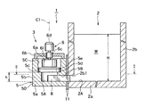
図1は本発明の実施形態としての非鉄金属の溶解炉1の縦断説明図、図2はそのII−II線に沿って切断した横断説明図である。これらの図から分かるように溶解炉1は、メインバス(溶解炉又は保持炉)としての炉本体2と、フランジ11を介して、それに連通状態に接続されたポンプとしての溶湯循環駆動装置3とを備える。
FIG. 1 is a longitudinal explanatory view of a non-ferrous
炉本体2は汎用の溶解炉と同様であり、特に図1からわかるように、上方が開放し内部に非鉄金属の溶湯Mを収納する溶湯収納室2Aを備え、投入した非鉄金属としてのアルミニウム等の切粉等を加熱して溶かすためのバーナー(図示せず)を備えている。
The furnace
より詳しくは、図1において、前記炉本体2においては、底壁2aと4つの側壁2bとにより前記溶湯収納室2Aを構成している。前記側壁2bの1つに前記溶湯循環駆動装置3と連通させる連通口2b1を開口している。この連通口2b1は、後述するところからわかるように、ポンプとしての前記溶湯循環駆動装置3の駆動力により、炉本体2と溶湯循環駆動装置3との間において溶湯Mを流出、流入させる連通口として機能する。つまり、連通口2b1を通じて、溶湯循環駆動装置3の吐出力により溶湯循環駆動装置3から炉本体2へ非鉄金属の溶湯Mを流入させ、逆に、溶湯循環駆動装置3の吸引力により炉本体2内の溶湯Mを溶湯循環駆動装置3へ流出させる。
More specifically, in FIG. 1, in the
前記炉本体2に連通状態に接続される前記溶湯循環駆動装置3は、特に図1から分かるように、6面のうちの1面(1側面)だけが図中横向に開放した密閉状態の駆動室5Aを有する溶湯駆動槽5と、その上方外部に設置される永久磁石を有する駆動装置6と、を備える。
As shown in FIG. 1, the molten metal
前記溶湯駆動槽5は、特に図3から分かるように、いわゆる一面だけが図中横向に開放した密閉槽として構成されている。つまり、その一側面に開口5Bを有し、駆動室5Aがその開口5Bを介して、前記炉本体2の前記連通口2b1及び前記炉本体2の溶湯収納室2Aと連通する。この溶湯駆動槽5を密閉型としたので、より大きな駆動力を得るために後述する永久磁石装置6aを高速で回転しても溶湯Mが飛散することは防ぐことができる。
As can be seen from FIG. 3 in particular, the molten
前記溶湯駆動槽5は、特に図2から分かるように、溶湯駆動槽5の駆動室5Aと炉本体2の溶湯収納室2Aとを結ぶ流路FCを、流れの方向に沿っての左右の吐出流路(又は吸い込み流路)FC1と吸い込み流路(吐出流路)FC2とに区画する仕切板8を有する。この仕切板8は、図1から分かるように、長手方向が流れの方向沿うように配置され、流路FCを左右の吐出流路FC1と吸い込み流路FC2に区画するものである。これにより、駆動室5A内の溶湯Mは、溶湯収納室2Aとの間で、左右の流路FC1,FC2に区画された状態で、流入、流出することになる。
As can be seen from FIG. 2 in particular, the molten
前記仕切板8は直立状態に設けられ、前記溶湯駆動槽5の駆動室5Aに対して着脱可能とされ、高温の溶湯Mによって仕切板8が経年的に損傷した場合等でも、メンテナンスが容易に行えるようになっている。前記仕切板8の外端は前記開口5Bの領域に位置し、内端は前記駆動室5Aの内部に位置し、前記内端に向かい合う前記駆動室5Aの内面と前記内端との間に溶湯回転用隙間Sが形成されている。前記仕切板8は前記駆動室5Aの前記開口(流路FC)を前記仕切板8の左右両側の第1開口(流路FC1)と第2開口(流路FC2)とに区画し、前記溶湯駆動装置6により回転させられて前記仕切板8の一面に衝突した溶湯を前記第1開口から吐出させ、溶湯の圧力が低くなった前記駆動室へ前記第2開口から外部の溶湯を吸引可能としている。且つ、前記仕切板8は、特に図4から分かるように、溶湯駆動槽5に対して、いわゆる船の舵のように、垂直な軸線(第2の縦向きの軸線)C2の回りに回動可能とされ、且つその位置を保持可能としている。つまり、仕切板8は角度調節可能に取り付けられている。つまり、仕切板8を、仕切板8の長手方向の一端におけるほぼ垂直な軸線C2の回りに回動させその位置を保持可能としている。例えば、仕切板8は、図4において、流路FCの真ん中にある位置P0の他、例えば、左右に舵を切った状態の位置P1,P2を採ることができる。これにより、図4から分かるように、上方から見た場合の吐出流路FC1と吸い込み流路FC2の幅、テーパ等を変化させて、溶湯Mがより効率的に、前記駆動室5Aと前記溶湯収納室2Aとの間で、前記駆動室5Aから吐出し且つ駆動室5Aへ流入する状態を採りうるようにしている。これにより、後述するように、溶湯収納室2A内の溶湯Mが可及的に高速で回転するようにすることができる。
The
前記溶湯駆動槽5はより詳しくは以下の構造を有する。即ち、特に図3から分かるように、この溶湯駆動槽5は、底壁5aと四方を囲む4つの側壁5bにより構成される上方が開放したほぼ容器状の槽本体50を有する。4つの側壁5bの1つに開口5Bを形成している。この開口5Bを、図1から分かるように、前記炉本体2の連通口2b1と連通させて、前記駆動室5Aと前記溶湯収納室2Aとを連通している。4つの側壁5bの肉厚部分を座ぐって、つまり、4つの側壁5bの内面側を上端面から下方途中まで円形に座ぐることにより、環状の段差(座)5cを形成している。この座ぐった段差5cに耐火材で作った円盤状の上蓋5dを落とし蓋状態に且つ密閉状態に嵌め込み、さらにこの上蓋5d上に耐火材製の断熱板5eを載置している。これにより、前記上蓋5dと4つの側壁5bによって、上方が開放した永久磁石収納空間5Cが形成される。この永久磁石収納空間5Cに前記駆動装置6の永久磁石装置6aが軸線(第1の縦向きの軸線)C1の回りに回転可能に収納される。
More specifically, the molten
より詳しくは、前記駆動装置6はほぼ鍋蓋状の支持フレーム6bを有する。この支持フレーム6bを前記溶湯駆動槽5の4つの側壁5bの天面上に載置固定する。この支持フレーム6bの中心部分に取り付けた軸受6cで、前記永久磁石装置6aを回転可能に軸受けする。この永久磁石装置6aの軸61の上方側を駆動用電動機6dで駆動可能としている。この駆動用電動機6dは外部制御盤(図示せず)に接続され、その外部制御盤で回転制御可能とされている。前記永久磁石装置6aは、図1において、可及的に断熱板5eに接近した状態に設けられる。これにより、後述するところから分かるように、永久磁石装置6aからの磁力線MLが、断熱板5eと上蓋5dを貫通した後、さらに前記駆動室5A内の溶湯Mに高密度で貫通する。
More specifically, the driving
前記永久磁石装置6aの詳細は図5(a)、(b)に示される。図5(a)は永久磁石装置6aを底面から見た底面説明図、(b)は図1と同様に横方向からみた正面説明図である。図5(b)から分かるように、前記軸61に回転板62が固定されている。回転板62の底面には、図5(a)から分かるように、4つの永久磁石63が90度間隔で放射状に固定されている。図5(b)からわかるように、4つの永久磁石63は垂直方向に磁化されたものであり、図5(a)からわかるように、下端面の磁極はN極とS極とが交互に並ぶように磁化されている。これにより、N極から出た磁力線MLは、図5(b)に示すように、すぐ隣り合うS極に入る。つまり、磁力線MLは高密度のままN極からS極へ入ることとなる。N極から出た磁力線MLは、図1からわかるように、断熱板5e及び上蓋5dを貫通して駆動室5A内の溶湯Mを貫き、その後反転して今度は逆の順序で上蓋5d及び断熱板5eを貫通して、隣り合うS極へ入る。このように、磁力線MLは溶湯Mを貫通していることから、回転板62をつまり永久磁石63を、例えば左回りに回転させると、溶湯M中を磁力線MLが移動して渦電流が発生し、溶湯Mは永久磁石63と同じ方向に回転することになる。永久磁石63の回転速度を上げると溶湯Mの回転速度も上がる。而して、従来は、高温で作業者が浴びると危険な溶湯Mが駆動室5Aの側壁5bを乗り越えて外部に飛散してしまうことが有った。しかしながら、本実施形態では、駆動室5Aを上蓋5dで密閉状態に覆うようにしたので、溶湯Mの回転速度が上がっても、溶湯Mが側壁5bを乗り越えて駆動室5Aから外部に飛散するのは確実に防止される。よって、永久磁石装置6aの回転速度をより上げて、駆動室5A内の溶湯Mをより強力に駆動して炉本体2に吐出させ、炉本体2から吸引することができる。ひいては、炉本体2の溶湯収納室2A内の溶湯Mをより高速且つ強力に駆動することも可能である。
Details of the
上記したところから分かるように、溶湯収納室2Aでの溶湯Mの循環量は永久磁石装置6a回転数に比例するため、必要な循環量を外部電源制御盤により任意に調整可能である。これにより、溶湯駆動槽5を形成する耐火材の厚み設定の際の制限は全くなく、任意に決定でき、従って溶湯漏れの心配がある場合等は安全を見て厚くすることも可能である。
As can be seen from the above, since the circulation amount of the molten metal M in the molten
以上の説明で溶湯循環駆動装置3の動作がほぼ分かったと思うが、以下により詳しく説明する。
Although it is considered that the operation of the molten metal
図6(a)―(d)は溶湯循環駆動装置3における駆動室5A内での永久磁石装置6aの駆動による溶湯Mの流れを説明するための説明図である。
6A to 6D are explanatory views for explaining the flow of the molten metal M by driving the
図6(a)は、仕切板8の無い場合を示している。この場合においては、永久磁石装置6aの回転に伴って、溶湯Mは駆動室5A内で破線で示すように単に回転する。
FIG. 6A shows a case where the
図6(b)は仕切板8が図中水平にセットされた場合を示す。この場合においては、永久磁石装置6aの左回り回転に伴って溶湯Mも左回りに回転するが、回転する溶湯Mが仕切板8の図中下面に衝突し、流れの方向が右側に変えられ、溶湯Mはいわゆる吐出流FObとして右側の溶湯収納室2Aに流出する。これに伴って前記駆動室5A内の溶湯の圧力が低下し、溶湯収納室2A中の溶湯Mが吸引流FIbとして図中左側の駆動室5A内へ吸い込まれる。
FIG. 6B shows a case where the
図6(c)、(c)は仕切板8を図中やや上向き、下向きに切り換えた場合を示す。この場合においても駆動室5A内の溶湯Mには前述したところと同様に左回りの駆動力が作用し、吐出流FOc、FOdと吸引流FIc、FIdとが発生する。これらの吐出流FOc、FOdと吸引流FIc、FIdは図6(b)のものとは流出、流入の角度が異なったものとなっている。
FIGS. 6C and 6C show a case where the
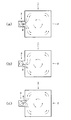
このように、図6(b)、(c)、(d)に示すように、仕切板8の向きを変えることにより、溶湯Mの吐出流FOiと吸引流FIiの向きを変えることができる。これにより、駆動室5Aに連通する溶湯収納室2A内での溶湯Mの流れ方を変えることができる。つまり、溶湯循環駆動装置3を炉本体2に連通状態に付設すると、駆動室5Aでの溶湯Mの左回りの回転に伴って炉本体2における溶湯収納室2A内の溶湯Mも左回りに回転するが、その回転における溶湯Mの流れの態様が装置毎にあるいは投入する非鉄金属の種類や量、溶湯Mの温度等の各種のパラメータに応じて違った態様となる。各態様の中から、炉本体2でもっとも効率良く投入非鉄金属を溶解させる回転を行わせるように、仕切板8の角度を調節することができる。
Thus, as shown in FIGS. 6B, 6C, and 6D, by changing the direction of the
仕切板8の角度と溶湯収納室2A内の溶湯Mの回転の態様を図7(a)−(c)に概略的に示す。これらの図は、仕切板8を舵のように向きを変えれば炉本体2での溶湯Mの流れが変化ことを説明図するために例示的に作成した概念図であって、炉本体2での溶湯Mの流れを正確に表すものではない。溶湯Mの流れは流路だけでなく、流速(回転周期)によっても決まり、さらには投入する非鉄金属の種類にも影響され、仕切板8の切り換えの位置が例えば目で見て決められる。
7A to 7C schematically show the angle of the
また、永久磁石装置6aの回転の方向も、上記の場合とは逆に、時計回りとすることもできる。このようにして、炉本体2における溶湯Mの最適な回転を検索するようにすることもできる。
Also, the direction of rotation of the
さらに、炉本体2への溶湯循環駆動装置3の取り付ける位置も種々変えた実施形態を採ることもできる。図8(a)−(c)、図9(a)−(c)は、それぞれ、溶湯循環駆動装置3を炉本体2の一側面の図中中央部、上端近くとした実施形態を示すものである。
Furthermore, the embodiment in which the position where the molten metal
なお、図1からわかるように、互いに連通させる炉本体2と溶湯循環駆動装置3において、駆動室5Aの高さhと溶湯収納室2Aに収納する溶湯Mの高さHとは、h<H、とすることが重要である。
As can be seen from FIG. 1, in the furnace
h>Hの場合でも駆動室5A内の溶湯は移動磁界により回転を始めるが、駆動室5A内の溶湯Mの上面と上蓋5dの下面との間に隙間ができ、駆動室5A内部の溶湯が複雑な動きをしてしまい、十分な循環量が確保できなくなる場合もある。これに対し、h<Hであれば駆動室5A内での圧力が高まり、吐出側に抵抗が存在したとしても十分に溶湯の吐出ができる。
Even when h> H, the molten metal in the driving
本発明者は、本発明の実施形態における溶湯循環駆動装置3の効果を確認すべく以下の条件で実験を行った。
The present inventor conducted an experiment under the following conditions in order to confirm the effect of the molten metal
駆動室5Aの内径φ:900mm
駆動用電動機6dの使用電力:5.5Kw
溶湯槽高さh:300mm
仕切板8:図6(b)のニュートラル位置
その結果は以下の通りである。即ち、図6(b)において、吐出流FObの流速(溶湯流速m/min)とその流量(流量Tons/h)は以下の通りである。
Inner diameter of
Electric power used by the
Molten bath height h: 300 mm
Partition plate 8: neutral position in FIG. 6 (b) The results are as follows. That is, in FIG. 6B, the flow rate of the discharge flow FOb (molten flow rate m / min) and the flow rate (flow rate Tons / h) are as follows.
溶湯流速m/min 流量Tons/h
70 1260
80 1440
90 1620
100 1800
これは従来型機種と比較すれば
メカニカルポンプ方式 2〜3倍
床置き式攪拌装置 2倍
縦軸式攪拌装置 0.8倍
横置き型攪拌装置 1.0倍
電磁式攪拌装置 2〜3倍
に匹敵する結果となっている。
Molten metal flow rate m / min Flow rate Tons / h
70 1260
80 1440
90 1620
100 1800
This is compared to the conventional model
Mechanical pump system 2-3 times
Floor-
Vertical stirrer 0.8 times
Horizontal type stirring device 1.0 times
The result is comparable to 2 to 3 times the electromagnetic stirring device.
以上説明した本発明の実施形態によれば以下の効果が得られる。 According to the embodiment of the present invention described above, the following effects can be obtained.
(1)溶湯循環駆動装置3は非常にコンパクトとしつつも大きな溶湯循環量が得られる。
(2)溶湯収納室2A内の点検は上蓋5d、断熱板5eを外すことにより極めて容易に行うことができる。
(3)駆動室5Aから外部へ溶湯が飛散等によって漏れはない。
(4)仕切板8は交換可能としたので、摩耗した場合においても、交換可能であり、且つその交換作業は構造上短時間で行える。
(5)結果的にメンテナンスのための操業停止時間は極めて短時間なものとすることができる。
(6)駆動装置6は溶湯駆動槽5へ外付けするように構成したので、駆動装置6自体のメンテナンスを極めて容易に行うことができる。
(7)溶湯循環駆動装置3と炉本体2とをフランジ接続で組み立てるようにしたので、組み立てや解体も短時間でできる。
(8)溶湯循環駆動装置3には補強用ステンレス板を設ける必要がないため、発熱の心配がなく、設計に柔軟性を持たせることができる。
(9)ステンレス板を不要としたため、エネルギーロスを従来式の1/4以下に抑えることができる。
(10)溶湯循環駆動装置3を、炉本体(溶解炉、保持炉、メインバス)2に対し、炉本体2の側方に位置させた状態で取り付け、溶湯循環駆動装置3と炉本体2との連通を、溶湯循環駆動装置3の溶湯駆動槽5の開口5Bと、炉本体2の側壁2bに穿けた連通口2b1とを連通させることにより達成するという構造を採用した。
(1) The molten metal
(2) Inspection in the molten
(3) There is no leakage due to scattering of molten metal from the driving
(4) Since the
(5) As a result, the operation stop time for maintenance can be extremely short.
(6) Since the
(7) Since the molten metal
(8) Since there is no need to provide a reinforcing stainless steel plate in the molten metal
(9) Since a stainless steel plate is not required, energy loss can be suppressed to ¼ or less of the conventional type.
(10) The molten metal
Claims (7)
密閉状態に構成された駆動室を有し、前記駆動室は前記溶湯収納室と連通させるための開口を有し、前記開口から流入する溶湯を前記駆動室に収納する、溶湯駆動槽と、
前記溶湯駆動槽の上方に設置される溶湯駆動装置であって、前記溶湯駆動槽の前記駆動室内の溶湯に磁力線を縦向きに貫通させた状態で第1の縦向きの軸線の回りに回転可能な永久磁石装置と、前記永久磁石装置を回転駆動することにより前記駆動室内の溶湯を前記第1の縦向きの軸線の回りに回転させる永久磁石装置用駆動装置と、を有する、溶湯駆動装置と、
前記溶湯駆動槽の前記駆動室内に、前記駆動室と前記溶湯収納室とが連通する方向に沿って直立状態に配置された仕切板であって、前記仕切板の外端は前記開口の領域に位置し、内端は前記駆動室の内部に位置し、前記内端に向かい合う前記駆動室の内面と前記内端との間に溶湯回転用隙間が形成されており、前記仕切板は前記駆動室の前記開口を前記仕切板の左右両側の第1開口と第2開口とに区画し、前記溶湯駆動装置により回転させられて前記仕切板の一面に衝突した溶湯を前記第1開口から吐出させ、溶湯の圧力が低くなった前記駆動室へ前記第2開口から外部の溶湯を吸引可能とする、仕切板と、
を備えたことを特徴とする溶湯循環駆動装置。 A molten metal circulation driving device for agitating and driving a non-ferrous metal melt in a melt storage chamber that is attached to a side wall of the main bath and stores a non-ferrous metal melt in the main bath,
A driving chamber configured in a sealed state, the driving chamber having an opening for communicating with the molten metal storage chamber, and a molten metal driving tank for storing the molten metal flowing in from the opening in the driving chamber;
A molten metal driving device installed above the molten metal driving tank, wherein the molten metal in the driving chamber of the molten metal driving tank is capable of rotating around a first vertical axis in a state in which magnetic lines of force penetrate vertically. A permanent magnet device, and a drive device for a permanent magnet device that rotates the permanent magnet device around the first longitudinal axis by rotating the permanent magnet device. ,
A partition plate arranged in an upright state in the drive chamber of the melt drive tank along a direction in which the drive chamber and the melt storage chamber communicate with each other, and an outer end of the partition plate is located in the region of the opening The inner end is located inside the drive chamber, a gap for rotating the melt is formed between the inner surface of the drive chamber facing the inner end and the inner end, and the partition plate is formed in the drive chamber The opening of the partition plate is divided into first and second openings on the left and right sides of the partition plate, and the molten metal rotated by the melt driving device and colliding with one surface of the partition plate is discharged from the first opening, A partition plate capable of sucking an external molten metal from the second opening to the drive chamber in which the pressure of the molten metal is low;
A molten metal circulation drive device characterized by comprising:
Priority Applications (9)
| Application Number | Priority Date | Filing Date | Title |
|---|---|---|---|
| JP2013090729A JP5813693B2 (en) | 2013-04-23 | 2013-04-23 | Molten metal circulation drive device and main bus having the same |
| KR1020147021315A KR101613927B1 (en) | 2013-04-23 | 2014-03-31 | Metal melt circulating drive device and main bath including the same |
| PCT/JP2014/059414 WO2014175002A1 (en) | 2013-04-23 | 2014-03-31 | Molten metal circulation driving device and melting furnace having same |
| US14/391,522 US9597726B2 (en) | 2013-04-23 | 2014-03-31 | Metal melt circulating drive device and main bath including the same |
| EP14730728.4A EP2944396B1 (en) | 2013-04-23 | 2014-03-31 | Molten metal circulation driving device and melting furnace having same |
| CA2861635A CA2861635C (en) | 2013-04-23 | 2014-03-31 | Metal melt circulating drive device and main bath including the same |
| AU2014203045A AU2014203045B2 (en) | 2013-04-23 | 2014-03-31 | Metal melt circulating drive device and main bath including the same |
| CN201420201349.7U CN204007188U (en) | 2013-04-23 | 2014-04-23 | Motlten metal circulating driving device and there is its smelting furnace |
| CN201410165947.8A CN104121787B (en) | 2013-04-23 | 2014-04-23 | Motlten metal circulating driving device and there is its smelting furnace |
Applications Claiming Priority (1)
| Application Number | Priority Date | Filing Date | Title |
|---|---|---|---|
| JP2013090729A JP5813693B2 (en) | 2013-04-23 | 2013-04-23 | Molten metal circulation drive device and main bus having the same |
Publications (3)
| Publication Number | Publication Date |
|---|---|
| JP2014213333A JP2014213333A (en) | 2014-11-17 |
| JP2014213333A5 JP2014213333A5 (en) | 2015-07-02 |
| JP5813693B2 true JP5813693B2 (en) | 2015-11-17 |
Family
ID=51767305
Family Applications (1)
| Application Number | Title | Priority Date | Filing Date |
|---|---|---|---|
| JP2013090729A Active JP5813693B2 (en) | 2013-04-23 | 2013-04-23 | Molten metal circulation drive device and main bus having the same |
Country Status (8)
| Country | Link |
|---|---|
| US (1) | US9597726B2 (en) |
| EP (1) | EP2944396B1 (en) |
| JP (1) | JP5813693B2 (en) |
| KR (1) | KR101613927B1 (en) |
| CN (2) | CN204007188U (en) |
| AU (1) | AU2014203045B2 (en) |
| CA (1) | CA2861635C (en) |
| WO (1) | WO2014175002A1 (en) |
Cited By (2)
| Publication number | Priority date | Publication date | Assignee | Title |
|---|---|---|---|---|
| KR20200048159A (en) * | 2018-10-29 | 2020-05-08 | 주식회사 포스코 | Apparatus and method for stirring molten material |
| WO2021112267A1 (en) * | 2019-12-02 | 2021-06-10 | 주식회사 포스코 | Molten material mixing apparatus and method |
Families Citing this family (9)
| Publication number | Priority date | Publication date | Assignee | Title |
|---|---|---|---|---|
| JP5795296B2 (en) * | 2012-09-27 | 2015-10-14 | 高橋 謙三 | Vortex chamber body for metal melting furnace and metal melting furnace using the same |
| JP5813693B2 (en) * | 2013-04-23 | 2015-11-17 | 高橋 謙三 | Molten metal circulation drive device and main bus having the same |
| JP6033807B2 (en) * | 2014-03-27 | 2016-11-30 | 高橋 謙三 | Metal melt stirring device and metal melt transfer device |
| JP6039010B1 (en) * | 2015-04-23 | 2016-12-07 | 高橋 謙三 | Conductive metal melting furnace, conductive metal melting furnace system including the same, and conductive metal melting method |
| EP3306245B1 (en) | 2015-06-03 | 2020-09-09 | Kenzo Takahashi | Conductive metal melting furnace, conductive metal melting furnace system equipped with same, and conductive metal melting method |
| MX2018000898A (en) * | 2015-07-23 | 2018-05-15 | Pyrotek Inc | Metallurgical apparatus. |
| RU2677549C2 (en) * | 2016-07-25 | 2019-01-17 | Общество с ограниченной ответственностью "Научно-производственный центр магнитной гидродинамики" | Method of remelting metal wastes and furnace for its implementation |
| AU2019237468B2 (en) * | 2018-03-20 | 2022-01-27 | Kenzo Takahashi | Molten metal pump and method of adjusting pumping capacity of molten metal pump |
| US11427492B2 (en) * | 2019-07-11 | 2022-08-30 | Owens-Brockway Glass Container Inc. | Multi-chamber submerged combustion melter and system |
Family Cites Families (14)
| Publication number | Priority date | Publication date | Assignee | Title |
|---|---|---|---|---|
| JP3598106B2 (en) * | 2002-05-09 | 2004-12-08 | 株式会社宮本工業所 | melting furnace |
| JP2006010214A (en) * | 2004-06-25 | 2006-01-12 | Miyamoto Kogyosho Co Ltd | Melting furnace |
| KR101213559B1 (en) * | 2004-12-22 | 2012-12-18 | 겐조 다카하시 | Apparatus and method for agitating, and melting furnace attached to agitation apparatus using agitation apparatus |
| JP4376771B2 (en) | 2004-12-22 | 2009-12-02 | 高橋 謙三 | Stirrer |
| CN200963579Y (en) * | 2006-11-02 | 2007-10-24 | 潍坊华特磁电设备有限公司 | Circulation type permanent magnetic mixer |
| JP5163615B2 (en) * | 2008-10-29 | 2013-03-13 | トヨタ自動車株式会社 | Stirring apparatus, dissolving apparatus and dissolving method |
| JP5485777B2 (en) * | 2009-06-02 | 2014-05-07 | 株式会社宮本工業所 | melting furnace |
| JP5485776B2 (en) * | 2009-06-02 | 2014-05-07 | 株式会社宮本工業所 | melting furnace |
| JP2010281474A (en) * | 2009-06-02 | 2010-12-16 | Miyamoto Kogyosho Co Ltd | Melting furnace |
| JP5550885B2 (en) | 2009-11-12 | 2014-07-16 | 高橋 謙三 | Melting furnace system |
| JP5546974B2 (en) * | 2010-04-07 | 2014-07-09 | 株式会社ヂーマグ | Non-ferrous metal melt pump and melting furnace system using the same |
| JP5766572B2 (en) * | 2011-09-30 | 2015-08-19 | 高橋 謙三 | Vortex chamber body for metal melting furnace and metal melting furnace using the same |
| JP5795296B2 (en) | 2012-09-27 | 2015-10-14 | 高橋 謙三 | Vortex chamber body for metal melting furnace and metal melting furnace using the same |
| JP5813693B2 (en) * | 2013-04-23 | 2015-11-17 | 高橋 謙三 | Molten metal circulation drive device and main bus having the same |
-
2013
- 2013-04-23 JP JP2013090729A patent/JP5813693B2/en active Active
-
2014
- 2014-03-31 US US14/391,522 patent/US9597726B2/en active Active
- 2014-03-31 WO PCT/JP2014/059414 patent/WO2014175002A1/en active Application Filing
- 2014-03-31 CA CA2861635A patent/CA2861635C/en active Active
- 2014-03-31 AU AU2014203045A patent/AU2014203045B2/en not_active Ceased
- 2014-03-31 EP EP14730728.4A patent/EP2944396B1/en active Active
- 2014-03-31 KR KR1020147021315A patent/KR101613927B1/en active IP Right Grant
- 2014-04-23 CN CN201420201349.7U patent/CN204007188U/en not_active Withdrawn - After Issue
- 2014-04-23 CN CN201410165947.8A patent/CN104121787B/en not_active Expired - Fee Related
Cited By (3)
| Publication number | Priority date | Publication date | Assignee | Title |
|---|---|---|---|---|
| KR20200048159A (en) * | 2018-10-29 | 2020-05-08 | 주식회사 포스코 | Apparatus and method for stirring molten material |
| KR102135760B1 (en) * | 2018-10-29 | 2020-07-20 | 주식회사 포스코 | Apparatus and method for stirring molten material |
| WO2021112267A1 (en) * | 2019-12-02 | 2021-06-10 | 주식회사 포스코 | Molten material mixing apparatus and method |
Also Published As
| Publication number | Publication date |
|---|---|
| EP2944396A1 (en) | 2015-11-18 |
| KR101613927B1 (en) | 2016-04-20 |
| CN204007188U (en) | 2014-12-10 |
| EP2944396B1 (en) | 2018-05-02 |
| KR20140146580A (en) | 2014-12-26 |
| CA2861635A1 (en) | 2014-10-23 |
| US20150283605A1 (en) | 2015-10-08 |
| CN104121787B (en) | 2016-03-30 |
| WO2014175002A1 (en) | 2014-10-30 |
| AU2014203045B2 (en) | 2015-08-27 |
| US9597726B2 (en) | 2017-03-21 |
| JP2014213333A (en) | 2014-11-17 |
| EP2944396A4 (en) | 2016-09-07 |
| AU2014203045A1 (en) | 2014-11-06 |
| CA2861635C (en) | 2016-09-27 |
| CN104121787A (en) | 2014-10-29 |
Similar Documents
| Publication | Publication Date | Title |
|---|---|---|
| JP5813693B2 (en) | Molten metal circulation drive device and main bus having the same | |
| EP1674814B1 (en) | Agitator, agitating method, and melting furnace with agitator | |
| JP4413786B2 (en) | Molten metal stirrer and non-ferrous metal melting furnace with stirrer | |
| JP5546974B2 (en) | Non-ferrous metal melt pump and melting furnace system using the same | |
| JP4376771B2 (en) | Stirrer | |
| EP2825678B1 (en) | Magnetic pump installation | |
| KR20140012184A (en) | Vortex chamber body for metal melting furnace, and metal melting furnace using said vortex chamber body | |
| JP5496647B2 (en) | Non-ferrous metal melt pump | |
| JP5485776B2 (en) | melting furnace | |
| JP5485777B2 (en) | melting furnace | |
| WO2019181884A1 (en) | Molten metal pump and method of adjusting pumping capacity of molten metal pump | |
| CN109440000A (en) | Amorphous alloy smelting furnace molten iron guiding device | |
| WO2022138198A1 (en) | Molten metal pump | |
| KR101307447B1 (en) | Supply pump for molten metals | |
| US10739074B2 (en) | Metallurgical apparatus | |
| US20230147586A1 (en) | Multi-purpose pump system for a metal furnace and related methods | |
| JP2009002643A (en) | Melting furnace with stirrer, and stirrer | |
| WO2021015210A1 (en) | Metal raw material melting device, molten metal melting and holding system, and metal raw material melting method | |
| KR20160012004A (en) | Chip melting and agitatiing device |
Legal Events
| Date | Code | Title | Description |
|---|---|---|---|
| A521 | Request for written amendment filed |
Free format text: JAPANESE INTERMEDIATE CODE: A523 Effective date: 20150515 |
|
| A621 | Written request for application examination |
Free format text: JAPANESE INTERMEDIATE CODE: A621 Effective date: 20150515 |
|
| A871 | Explanation of circumstances concerning accelerated examination |
Free format text: JAPANESE INTERMEDIATE CODE: A871 Effective date: 20150515 |
|
| A975 | Report on accelerated examination |
Free format text: JAPANESE INTERMEDIATE CODE: A971005 Effective date: 20150527 |
|
| A131 | Notification of reasons for refusal |
Free format text: JAPANESE INTERMEDIATE CODE: A131 Effective date: 20150609 |
|
| TRDD | Decision of grant or rejection written | ||
| A01 | Written decision to grant a patent or to grant a registration (utility model) |
Free format text: JAPANESE INTERMEDIATE CODE: A01 Effective date: 20150821 |
|
| A61 | First payment of annual fees (during grant procedure) |
Free format text: JAPANESE INTERMEDIATE CODE: A61 Effective date: 20150916 |
|
| R150 | Certificate of patent or registration of utility model |
Ref document number: 5813693 Country of ref document: JP Free format text: JAPANESE INTERMEDIATE CODE: R150 |
|
| R250 | Receipt of annual fees |
Free format text: JAPANESE INTERMEDIATE CODE: R250 |
|
| R250 | Receipt of annual fees |
Free format text: JAPANESE INTERMEDIATE CODE: R250 |
|
| R250 | Receipt of annual fees |
Free format text: JAPANESE INTERMEDIATE CODE: R250 |
|
| R250 | Receipt of annual fees |
Free format text: JAPANESE INTERMEDIATE CODE: R250 |
|
| R250 | Receipt of annual fees |
Free format text: JAPANESE INTERMEDIATE CODE: R250 |
|
| R250 | Receipt of annual fees |
Free format text: JAPANESE INTERMEDIATE CODE: R250 |
|
| R250 | Receipt of annual fees |
Free format text: JAPANESE INTERMEDIATE CODE: R250 |