WO2010044343A1 - 機能性気体を連続的に得る方法及び装置 - Google Patents
機能性気体を連続的に得る方法及び装置 Download PDFInfo
- Publication number
- WO2010044343A1 WO2010044343A1 PCT/JP2009/067012 JP2009067012W WO2010044343A1 WO 2010044343 A1 WO2010044343 A1 WO 2010044343A1 JP 2009067012 W JP2009067012 W JP 2009067012W WO 2010044343 A1 WO2010044343 A1 WO 2010044343A1
- Authority
- WO
- WIPO (PCT)
- Prior art keywords
- cylindrical body
- wall surface
- internal space
- gas
- cylinder
- Prior art date
- Legal status (The legal status is an assumption and is not a legal conclusion. Google has not performed a legal analysis and makes no representation as to the accuracy of the status listed.)
- Ceased
Links
Images

Classifications
-
- B—PERFORMING OPERATIONS; TRANSPORTING
- B01—PHYSICAL OR CHEMICAL PROCESSES OR APPARATUS IN GENERAL
- B01J—CHEMICAL OR PHYSICAL PROCESSES, e.g. CATALYSIS OR COLLOID CHEMISTRY; THEIR RELEVANT APPARATUS
- B01J19/00—Chemical, physical or physico-chemical processes in general; Their relevant apparatus
- B01J19/0053—Details of the reactor
- B01J19/006—Baffles
-
- B—PERFORMING OPERATIONS; TRANSPORTING
- B01—PHYSICAL OR CHEMICAL PROCESSES OR APPARATUS IN GENERAL
- B01J—CHEMICAL OR PHYSICAL PROCESSES, e.g. CATALYSIS OR COLLOID CHEMISTRY; THEIR RELEVANT APPARATUS
- B01J19/00—Chemical, physical or physico-chemical processes in general; Their relevant apparatus
- B01J19/24—Stationary reactors without moving elements inside
- B01J19/2415—Tubular reactors
-
- C—CHEMISTRY; METALLURGY
- C01—INORGANIC CHEMISTRY
- C01B—NON-METALLIC ELEMENTS; COMPOUNDS THEREOF; METALLOIDS OR COMPOUNDS THEREOF NOT COVERED BY SUBCLASS C01C
- C01B7/00—Halogens; Halogen acids
- C01B7/24—Inter-halogen compounds
-
- B—PERFORMING OPERATIONS; TRANSPORTING
- B01—PHYSICAL OR CHEMICAL PROCESSES OR APPARATUS IN GENERAL
- B01J—CHEMICAL OR PHYSICAL PROCESSES, e.g. CATALYSIS OR COLLOID CHEMISTRY; THEIR RELEVANT APPARATUS
- B01J2219/00—Chemical, physical or physico-chemical processes in general; Their relevant apparatus
- B01J2219/00049—Controlling or regulating processes
- B01J2219/00051—Controlling the temperature
- B01J2219/00074—Controlling the temperature by indirect heating or cooling employing heat exchange fluids
- B01J2219/00076—Controlling the temperature by indirect heating or cooling employing heat exchange fluids with heat exchange elements inside the reactor
- B01J2219/00085—Plates; Jackets; Cylinders
-
- B—PERFORMING OPERATIONS; TRANSPORTING
- B01—PHYSICAL OR CHEMICAL PROCESSES OR APPARATUS IN GENERAL
- B01J—CHEMICAL OR PHYSICAL PROCESSES, e.g. CATALYSIS OR COLLOID CHEMISTRY; THEIR RELEVANT APPARATUS
- B01J2219/00—Chemical, physical or physico-chemical processes in general; Their relevant apparatus
- B01J2219/00761—Details of the reactor
- B01J2219/00763—Baffles
- B01J2219/00765—Baffles attached to the reactor wall
- B01J2219/00768—Baffles attached to the reactor wall vertical
Definitions
- the present invention relates to a technique for continuously obtaining a functional gas such as an etching gas, a cleaning gas, and a raw material gas for forming a thin film by reacting plural kinds of raw material gases.
- a functional gas such as an etching gas, a cleaning gas, and a raw material gas for forming a thin film by reacting plural kinds of raw material gases.
- a technique for producing a functional material such as a functional gas by introducing a raw material gas into the inner space of a heated cylinder and causing the raw material gas to undergo a thermal reaction is known.
- the raw material gas is continuously introduced into the inner space of the cylinder, and the reaction product is introduced from the upstream side while causing the thermal reaction of the raw material gas. It is necessary to move to the downstream side and take out the reaction product from the internal space.
- Patent Document 1 in a coal direct liquefaction continuous reaction apparatus into which hydrogen is introduced, a system in which a heat coil is installed on the central axis in a cylinder constituting the reaction apparatus in order to improve thermal efficiency when the apparatus scale is expanded. Is disclosed.
- the raw material gas is a highly reactive material such as a fluorine compound
- the heating mechanism is severely deteriorated. This problem is particularly noticeable in a process in which a plurality of kinds of source gases are reacted by a thermal reaction.
- the present invention provides a method capable of continuously producing a functional gas by thermally reacting a plurality of types of source gases even when a highly reactive material such as a fluorine compound is used as the source gas.
- a highly reactive material such as a fluorine compound
- continuous means that a functional gas is generated by introducing and reacting raw materials without interruption during operation of technical means.
- the method for continuously obtaining the functional gas of the present invention is a method for continuously obtaining a functional gas by reacting a plurality of kinds of source gases, Introducing a plurality of kinds of source gases into the internal space of the cylinder whose outer wall is heated; Moving the source gas and reaction product gas introduced into the internal space of the cylindrical body from the upstream side to the downstream side of the internal space of the cylindrical body; Extracting the raw material gas and the reaction product gas from the internal space of the cylindrical body; In the step of moving, the source gas and the reaction product gas are opposed to the inner wall surface portion in the radial direction of the cylinder body from the inner wall surface portion of the cylinder facing the inner space of the cylinder body. The inner space of the cylinder is moved from the upstream side to the downstream side while moving toward the inner wall surface side. And reaction product gas, ie, functional gas, can be obtained continuously by continuing the above-mentioned three processes seamlessly.
- the inner wall surface of the cylinder is also heated by the heating of the outer wall even when the inner space of the cylinder is lower than the desired temperature.
- the source gas comes into contact with the inner wall surface or is in the vicinity of the inner wall surface, a plurality of types of source gases react by a thermal reaction, and a reaction product gas can be obtained.
- the inner wall surface portion of the cylindrical body, the inner wall surface portion and the cylindrical body Ribs extending substantially perpendicularly to each of these inner wall surface portions are formed from both the radially inner side wall surface portions, A plurality of the ribs are formed from the upstream side to the downstream side of the internal space of the cylindrical body, The ribs formed on the inner wall surface portion and the ribs formed on the inner wall surface portion on the opposite side in the radial direction of the cylindrical body are alternately arranged in the axial direction of the cylindrical body, thereby moving the movement.
- the inner space of the cylinder is moved from the upstream side to the downstream side while moving from the wall surface part to the inner wall surface part on the side facing the inner wall surface part in the radial direction of the cylinder.
- the source gas and the reaction product gas are separated from the inner wall surface portion of the cylindrical body on the side facing the inner wall surface portion in the radial direction of the cylindrical body.
- the inner space of the cylinder is easily moved from the upstream side to the downstream side while facing the wall surface.
- the rib is heated as the outer wall of the cylindrical body is heated, the thermal reaction efficiently occurs when the raw material gas flows along the rib, and the effect of generating the reaction product gas can be obtained. It is preferable to install ribs.
- the apparatus for continuously obtaining the functional gas of the present invention is for continuously obtaining a functional gas by reacting a plurality of kinds of source gases,
- a cylinder having an internal space and an outer wall provided outside the internal space;
- a rib extending in a substantially vertical direction with respect to each of the inner wall surface portions A plurality of the ribs are formed from the upstream side to the downstream side of the internal space of the cylindrical body, The ribs formed on the inner wall surface portion and the ribs formed on the inner wall surface portion on the opposite side in the radial direction of the cylindrical body are alternately arranged in the axial direction of the cylindrical body.
- the functional gas can be generated by introducing the raw material gas into the reaction system without interruption and reacting the raw material gas. And since the inner wall surface of the cylindrical body is heated through the heating of the outer wall, the source gas is reliably heated when the source gas contacts the inner wall surface or passes through the vicinity of the inner wall surface. The reaction can be carried out efficiently, and the reaction apparatus can be easily increased in size. In addition, since it is not necessary to provide a heater for heating in the system in which the thermal reaction of the raw material gas occurs, the maintenance of the apparatus is easy, and the raw material gas has a highly reactive material such as a fluorine compound. Even when used, it is also easy to produce a functional gas continuously for a long time by thermally reacting plural kinds of raw material gases.
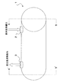
- FIG. 3 is a diagram showing a cross section of the device 1 along the line c-c ′ shown in FIG. 2.
- FIG. 1 is a perspective view of a main part of a device 1 preferably used in the present invention
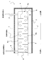
- FIG. 2 is a longitudinal sectional view taken along line ab-a′b ′ shown in the perspective view of the device 1 shown in FIG.
- FIG. 3 shows a cross-sectional view along the line cc ′ shown in the cross-sectional view of the device 1 shown in FIG.
- the apparatus 1 has a cylindrical body having an inner space 9 and an outer wall 5 provided outside the inner space 9.
- the cylindrical body is formed with a gas inlet 2 and a gas outlet 3 respectively communicating with the internal space 9.
- the raw material gas introduced from the gas introduction port 2 flows from the upstream side to the downstream side through the internal space 9 of the cylindrical body of the apparatus 1 while producing a reaction product. Then, the reaction product is taken out from the gas outlet 3. From the gas outlet 3, unreacted raw material gas can also be taken out.
- the gas flows from the inner wall surface portion 6b of the cylinder in the radial direction of the cylinder as shown in FIG.
- the internal space 9 is moved from the upstream side to the downstream side while facing the inner wall surface portion 6c on the side facing the wall surface portion 6b.
- a plate material 8 is provided in the downstream region of the internal space 9 to close the axial end of the cylinder and seal the internal space 9, and the gas flows along the plate material 8.
- a plurality of ribs 4 are formed from the upstream side to the downstream side of the internal space 9 of the cylindrical body as shown in FIG. 2 and extend from the inner wall surface portion 6b substantially perpendicular to the inner wall surface portion 6b; It is preferable that ribs 4 extending substantially perpendicularly to the inner wall surface portion 6c from the inner wall surface portion 6c on the side facing the inner wall surface portion 6b are alternately arranged in the axial direction of the cylinder.
- the raw material gas flows into the inner wall surface 6 (inner wall surface portion). 6a to 6c), the gas is surely heated when it passes or contacts, so that the raw material gas reacts by a thermal reaction, and a reaction product, that is, a functional gas can be generated.
- the embodiment in which the ribs 4 are provided as shown in FIG. 2 is preferable because the ribs 4 are also heated by heat transfer, so that the thermal reaction of the raw material gas becomes efficient.
- the total occupied area of the ribs 4 is preferably 50% or more and less than 100%, more preferably 50 to 95%, and even more preferably 75 to 85%. If it is less than 50%, the rib 4 tends to reduce the gas flowing from the upstream side toward the downstream side in the inner space 9 of the cylindrical body from the inner wall surface portion 6b toward the inner wall surface portion 6c. On the other hand, if it exceeds 95%, the pressure loss tends to increase, and the smooth flow of gas from the upstream side to the downstream side tends to be hindered.
- the distance between the rib 4 and the rib 4 arranged next to it is preferably 1/5 or more of the inner diameter of the cylinder because the gas flow may not be smooth if the distance is short. Moreover, since the effect of the rib 4 will become small if the said distance is too long, Preferably it shall be below the internal diameter of a cylinder.
- the material used for the rib 4 and the inner wall surface 6 is a highly reactive material such as a fluorine compound as a raw material gas
- a nickel-based metal material such as nickel or inconel is generally used. Although it is used, it is not particularly limited as long as it is thermally and chemically resistant.
- the material used for the outer wall 5 may be the same material as the inner wall surface 6, but is not particularly limited as long as it has heat resistance.
- examples of the functional gas obtained as a reaction product include chlorine trifluoride (ClF 3 ) obtained by reacting fluorine (F 2 ) and chlorine (Cl 2 ) at a temperature of about 300 ° C., Seven pentafluoride (BrF 5 ) obtained by reacting F 2 and bromine (Br 2 ) at a temperature of about 200 ° C., and seven obtained by reacting F 2 and iodine (I 2 ) at a temperature of about 250 ° C. Examples thereof include iodine fluoride (IF 7 ).
- this invention is not limited to the manufacturing method of above-described functional gas.
- Example 1 Preparation of apparatus for continuously obtaining functional gas
- An apparatus 1 having a main structure shown in FIGS. 1 to 3 was prepared as the general structure.
- the inner diameter of the cylinder was 300 mm, and the distance from the gas inlet 2 to the gas outlet 3 was 1 m.
- the distance between the rib 4 extending substantially perpendicular to the inner wall surface portion 6b from the inner wall surface portion 6b and the adjacent rib 4 extending substantially perpendicular to the inner wall surface portion 6c from the inner wall surface portion 6c is 75 mm. Thirteen ribs 4 were arranged from the upstream side to the downstream side of the internal space 9 of the cylinder.
- each rib 4 was set so that the occupied area of the rib 4 with respect to the internal space 9 of the cylindrical body when viewed in FIG. 3 was 80%. Then, heating of the heater 7 was started and the temperature of the inner wall surface 6 was kept so as to be 290 to 310 ° C.
- Comparative Example 1 The reaction was continuously performed in the same procedure as in Example 1 except that no rib 4 was provided. ClF 3 as a functional gas could be continuously taken out only at a rate of 1.6 SLM.
Landscapes
- Chemical & Material Sciences (AREA)
- Organic Chemistry (AREA)
- Chemical Kinetics & Catalysis (AREA)
- Inorganic Chemistry (AREA)
- Physical Or Chemical Processes And Apparatus (AREA)
Abstract
本発明の機能性気体を連続的に得る方法は、複数種の原料ガスを反応させて機能性気体を連続的に得る方法であり、複数種の原料ガスを外壁が加熱された筒体の内部空間へ導入する工程と、前記筒体の内部空間へ導入された原料ガス及び反応生成ガスを前記筒体の内部空間を上流側から下流側へと移動させる工程と、前記筒体の内部空間から原料ガスと反応生成ガスを取り出す工程と、を有し、前記移動させる工程にて、原料ガス及び反応生成ガスを、前記筒体の内部空間に臨む筒体の内壁面の部分から、該内壁面と前記筒体の径方向で対向する側の内壁面の部分へと向かわせながら前記筒体の内部空間を上流側から下流側へと移動させる。
Description
本発明は、複数種の原料ガスを反応させて、エッチングガス、クリーニングガス、薄膜形成のための原料ガス等の機能性気体を連続的に得る技術に関する。
加熱した筒体の内部空間に原料気体を導入し、原料気体を熱反応させることにより、機能性気体等の機能性材料を製造する技術が知られている。この技術において、機能性材料生産の効率化のためには、筒体の内部空間に原料気体を導入し続け、原料気体の熱反応を生じさせつつ、反応生成物を該内部空間を上流側から下流側へと移動させ、反応生成物を該内部空間から取り出す必要がある。
上記プロセスの効率化の一つのポイントに、筒体の内部空間に導入された原料気体を均一に加熱することがある。例えば、特許文献1では、水素が導入される石炭直接液化連続反応装置において、装置規模の拡大時の熱効率の改善のために、反応装置を構成する筒内の中心軸にヒートコイルを設置する方式を開示している。
原料気体がフッ素化合物等のように反応性の高いものの場合、例えば、特許文献1のように筒内に加熱機構を設ける方式では、加熱機構の劣化が激しいという問題が生じる。この問題は、特に熱反応によって、複数種の原料気体を反応させるプロセスでは顕著となる。
本発明は、原料気体にフッ素化合物等のように反応性の高いものを用いた場合でも、複数種の原料気体を熱反応させて、連続的に機能性気体を生産させることが可能な方法を提供することを課題とする。尚、本発明での「連続的」とは、技術手段の作動中に、原料を途切れなく導入して、反応させることにより機能性気体を生成することを意味している。
本発明の機能性気体を連続的に得る方法は、複数種の原料ガスを反応させて機能性気体を連続的に得る方法であり、該方法は、
外壁が加熱された筒体の内部空間へ複数種の原料ガスを導入する工程と、
前記筒体の内部空間へ導入された原料ガス及び反応生成ガスを、前記筒体の内部空間を上流側から下流側へと移動させる工程と、
前記筒体の内部空間から原料ガスと反応生成ガスを取り出す工程と、
を有し、前記移動させる工程において、原料ガス及び反応生成ガスを、前記筒体の内部空間に臨む筒体の内壁面の部分から、該内壁面の部分と前記筒体の径方向で対向する側の内壁面の部分へと向かわせながら前記筒体の内部空間を上流側から下流側へと移動させることを特徴としている。そして、前記3つの工程を切れ目なく続行させることにより反応生成ガス、すなわち機能性気体を連続的に得ることができる。
外壁が加熱された筒体の内部空間へ複数種の原料ガスを導入する工程と、
前記筒体の内部空間へ導入された原料ガス及び反応生成ガスを、前記筒体の内部空間を上流側から下流側へと移動させる工程と、
前記筒体の内部空間から原料ガスと反応生成ガスを取り出す工程と、
を有し、前記移動させる工程において、原料ガス及び反応生成ガスを、前記筒体の内部空間に臨む筒体の内壁面の部分から、該内壁面の部分と前記筒体の径方向で対向する側の内壁面の部分へと向かわせながら前記筒体の内部空間を上流側から下流側へと移動させることを特徴としている。そして、前記3つの工程を切れ目なく続行させることにより反応生成ガス、すなわち機能性気体を連続的に得ることができる。
複数種の原料ガスが導入される筒体の外壁を加熱することによって、筒体の内部空間が所望の温度より低い場合でも、外壁の加熱により筒体の内壁面も加熱された状態にあるので、原料ガスが内壁面に接触したとき、又は内壁面近傍にあるときに熱反応によって複数種の原料ガスが反応し、反応生成ガスを得ることができる。
また、本発明では、原料ガスが筒体の内壁面と接触、又は筒体の内壁面近傍を通過しやすくするために、筒体の内壁面の部分と、該内壁面の部分と筒体の径方向で対向する側の内壁面の部分との双方から、これらの内壁面の部分それぞれに対して略垂直に延びるリブが形成され、
該リブは筒体の内部空間の上流側から下流側に向けて複数形成され、
前記内壁面の部分に形成されるリブと、前記筒体の径方向で対向する側の内壁面の部分に形成されるリブとを、筒体の軸方向で交互に配置することで、前記移動させる工程(筒体の内部空間へ導入された原料ガス及び反応生成ガスを筒体の内部空間を上流側から下流側へと移動させる工程)において、原料ガス及び反応生成ガスを、筒体の内壁面の部分から、該内壁面の部分と筒体の径方向で対向する側の内壁面の部分へと向かわせながら、筒体の内部空間を上流側から下流側へと移動させる。
該リブは筒体の内部空間の上流側から下流側に向けて複数形成され、
前記内壁面の部分に形成されるリブと、前記筒体の径方向で対向する側の内壁面の部分に形成されるリブとを、筒体の軸方向で交互に配置することで、前記移動させる工程(筒体の内部空間へ導入された原料ガス及び反応生成ガスを筒体の内部空間を上流側から下流側へと移動させる工程)において、原料ガス及び反応生成ガスを、筒体の内壁面の部分から、該内壁面の部分と筒体の径方向で対向する側の内壁面の部分へと向かわせながら、筒体の内部空間を上流側から下流側へと移動させる。
前述のように筒体の内壁面にリブを設置することにより、原料ガス及び反応生成ガスが、筒体の内壁面の部分から該内壁面の部分と筒体の径方向で対向する側の内壁面の部分へと向かいながら筒体の内部空間を上流側から下流側へと移動しやすくする。また、筒体の外壁の加熱に伴い、リブが加熱されるため、原料ガスがリブに沿って流れる際にも効率的に熱反応が生じ、反応生成ガスを生成する効果も得られるので、前述のリブの設置は好ましい。
さらに本発明の機能性気体を連続的に得るための装置は、複数種の原料ガスを反応させて機能性気体を連続的に得るためのものであり、
内部空間と、該内部空間の外側に設けた外壁とを有する筒体と、
前記外壁が加熱されたときに前記筒体の内部空間へ複数種の原料ガスを導入する部位と、
前記筒体の内部空間へ導入された原料ガス及び反応生成ガスを前記筒体の内部空間の上流側から下流側へと移動させる部位と、
前記筒体の内部空間から原料ガスと反応生成ガスを取り出す部位と、
を有し、
前記移動させる部位には、原料ガス及び反応生成ガスを、前記筒体の内部空間に臨む前記筒体の内壁面の部分から、該内壁面の部分と前記筒体の径方向で対向する側の内壁面の部分へと向かわせながら前記筒体の内部空間を上流側から下流側へと移動させるように、前記内壁面の部分と、前記筒体の径方向で対向する側の内壁面の部分との双方から、これらの内壁面の部分それぞれに対して略垂直方向に延びるリブが形成され、
該リブは、前記筒体の内部空間の上流側から下流側に向けて複数形成され、
前記内壁面の部分に形成されるリブと、前記筒体の径方向で対向する側の内壁面の部分に形成されるリブとは、前記筒体の軸方向で交互に配置されることを特徴とする。
内部空間と、該内部空間の外側に設けた外壁とを有する筒体と、
前記外壁が加熱されたときに前記筒体の内部空間へ複数種の原料ガスを導入する部位と、
前記筒体の内部空間へ導入された原料ガス及び反応生成ガスを前記筒体の内部空間の上流側から下流側へと移動させる部位と、
前記筒体の内部空間から原料ガスと反応生成ガスを取り出す部位と、
を有し、
前記移動させる部位には、原料ガス及び反応生成ガスを、前記筒体の内部空間に臨む前記筒体の内壁面の部分から、該内壁面の部分と前記筒体の径方向で対向する側の内壁面の部分へと向かわせながら前記筒体の内部空間を上流側から下流側へと移動させるように、前記内壁面の部分と、前記筒体の径方向で対向する側の内壁面の部分との双方から、これらの内壁面の部分それぞれに対して略垂直方向に延びるリブが形成され、
該リブは、前記筒体の内部空間の上流側から下流側に向けて複数形成され、
前記内壁面の部分に形成されるリブと、前記筒体の径方向で対向する側の内壁面の部分に形成されるリブとは、前記筒体の軸方向で交互に配置されることを特徴とする。
本発明の好適な態様では、原料気体を反応系に途切れなく導入して、原料気体を反応させることにより機能性気体を生成し得る。そして、筒体の内壁面が外壁の加熱を通じて加熱された状態にあるので、原料気体が該内壁面へ接触した時、又は該内壁面の近傍を通過した時に、原料気体が確実に熱せられるので、反応を効率的に行え、反応装置の大サイズ化にも容易に対応できる。また、加熱のためのヒーター等を原料気体の熱反応が生じる系内に設けなくてもよいので、装置のメンテナンスも容易であるし、原料気体にフッ素化合物等のように反応性の高いものを用いた場合でも、複数種の原料気体を熱反応させて、連続的に機能性気体を長時間生産することも容易である。
本発明の機能性気体を連続的に得る方法に好適に用いられる装置を、図面を用いて説明する。図1は、本発明で好適に用いられる装置1の要部の斜視図、図2は図1に示した装置1の斜視図中で示したab-a’b’線に沿った縦断面図、図3は図2に示した装置1の断面図中で示したc-c’線に沿った横断面図を示す。
装置1は、内部空間9と、該内部空間9の外側に設けられた外壁5とを有する筒体を有する。該筒体には、内部空間9とそれぞれ連通する気体導入口2と、気体取出口3とが形成されている。気体導入口2から導入された原料気体は、装置1の筒体の内部空間9を、反応生成物を生じながら上流側から下流側へと流れる。そして、反応生成物は、気体取出口3から取り出される。気体取出口3からは、未反応の原料気体も取り出され得る。
気体は、筒体の内部空間9に臨む内壁面6の部分6bに形成されたリブ4の存在によって、図2に図示したように、筒体の内壁面部分6bから筒体の径方向で内壁面部分6bと対向する側の内壁面部分6cへと向かいながら内部空間9を上流側から下流側へと移動する。図2の態様では、内部空間9の下流域において、筒体の軸方向の一端部を閉鎖して内部空間9を封止する板材8が設けられ、該板材8に沿って気体が流れ、気体取出口3から反応生成物等を取り出しているが、他の態様として内部空間9の最下流域から反応生成物等を取り出してもよい。
前記リブ4は、図2のように筒体の内部空間9の上流側から下流側に向けて複数形成され、内壁面部分6bから該内壁面部分6bに対して略垂直に延びるリブ4と、内壁面部分6bと対向する側の内壁面部分6cから該内壁面部分6cに対して略垂直に延びるリブ4とを、筒体の軸方向で交互に配置することが好ましい。このようにリブ4を配置することで、筒体の内部空間9を流れる気体が、内壁面部分6bから内壁面部分6cに向かうことにより内部空間9の上流側から下流側へと流れやすくなる。また、筒体の内部空間9に配置されるリブの数は、筒体の大きさや、原料気体の種類により適宜設定される。
筒体の内部空間9に臨む内壁面6(内壁面部分6a乃至6c)は、外壁5の外側に設けられたヒーター7により外壁5を通じて加熱されるので、原料気体は内壁面6(内壁面部分6a乃至6c)の近傍を通過したときや接触したときに確実に加熱された状態となるので、熱反応により原料気体が反応し、反応生成物、すなわち機能性気体を生成することができる。
また、図2のようにリブ4を設ける態様は、リブ4が伝熱によっても加熱されるので原料気体の熱反応が効率化するので好ましい。
装置1の図2のc-c’線に沿った断面を見たとき、筒体の内部空間9(図3においては、リブ4と、リブ4と内壁面部分6bとによって形成される隙間10の総面積)に対するリブ4の占有面積は、好ましくは50%以上100%未満、より好ましくは50~95%、さらには好ましくは75~85%の範囲とする。50%未満では、リブ4によって、内壁面部分6bから内壁面部分6cに向かって筒体の内部空間9を上流側から下流側へと流れる気体が少なくなりやすい。他方、95%超では、圧力損失が大きくなる傾向があり、上流側から下流側への気体のスムーズな流れが妨げられやすい。
リブ4とその隣に配置されたリブ4との距離は、当該距離が短いと気体の流れがスムーズとならないことがあるので、好ましくは筒体の内径の1/5以上、とされる。また、当該距離が長すぎると、リブ4の効果が小さいものとなるので、好ましくは筒体の内径以下とされる。
リブ4および内壁面6(内壁面部分6a乃至6c)に用いる材質は、原料気体にフッ素化合物等のように反応性の高いものを用いる場合は、ニッケルやインコネルのようなニッケル系金属材料が一般に使用されるが、熱的及び化学的に耐性があれば特に限定されない。また、外壁5に用いる材質は、内壁面6と同じ材料でもよいが、耐熱性があれば特に限定されない。
本発明において、反応生成物として得られる機能性気体としては、例えば、フッ素(F2)と塩素(Cl2)を300℃前後の温度で反応させて得られる三フッ化塩素(ClF3)、F2と臭素(Br2)を200℃前後の温度で反応させて得られる五フッ化臭素(BrF5)、F2とヨウ素(I2)を250℃前後の温度で反応させて得られる七フッ化ヨウ素(IF7)等が挙げられる。なお、本発明は、上記した機能性気体の製造方法に限定されるものではない。
実施例1
1.機能性気体を連続的に得るための装置の準備
該略構造として、図1乃至3に示す要部構造を有する装置1を準備した。筒体の内径は300mm、気体導入口2から気体取出口3までの距離は1mとした。また、内壁面部分6bから該内壁面部分6bに対して略垂直に延びるリブ4と、内壁面部分6cから該内壁面部分6cに対して略垂直に延びる隣のリブ4との距離を75mmとし、筒体の内部空間9の上流側から下流側にかけてリブ4を13個配置した。さらに、各リブ4の大きさは、図3でみたときの筒体の内部空間9に対するリブ4の占有面積が80%となるようにした。そして、ヒーター7の加熱を開始し、内壁面6の温度が290~310℃となるように保持し続けた。
1.機能性気体を連続的に得るための装置の準備
該略構造として、図1乃至3に示す要部構造を有する装置1を準備した。筒体の内径は300mm、気体導入口2から気体取出口3までの距離は1mとした。また、内壁面部分6bから該内壁面部分6bに対して略垂直に延びるリブ4と、内壁面部分6cから該内壁面部分6cに対して略垂直に延びる隣のリブ4との距離を75mmとし、筒体の内部空間9の上流側から下流側にかけてリブ4を13個配置した。さらに、各リブ4の大きさは、図3でみたときの筒体の内部空間9に対するリブ4の占有面積が80%となるようにした。そして、ヒーター7の加熱を開始し、内壁面6の温度が290~310℃となるように保持し続けた。
2.機能性気体の連続的合成
気体導入口2から原料気体としてF2とCl2を、希釈ガスとしてN2をそれぞれ4.5SLM、1.5SLM、8.5SLMの速度で筒体の内部空間9に導入し続け、気体取出口3より反応生成物ClF3を機能性気体として2.25SLMの速度で連続的に取り出した。
気体導入口2から原料気体としてF2とCl2を、希釈ガスとしてN2をそれぞれ4.5SLM、1.5SLM、8.5SLMの速度で筒体の内部空間9に導入し続け、気体取出口3より反応生成物ClF3を機能性気体として2.25SLMの速度で連続的に取り出した。
比較例1
リブ4を全く設けなかった以外は、実施例1と同様の手順で連続的に反応を行った。機能性気体としてのClF3を1.6SLMの速度でしか連続的に取り出せなかった。
リブ4を全く設けなかった以外は、実施例1と同様の手順で連続的に反応を行った。機能性気体としてのClF3を1.6SLMの速度でしか連続的に取り出せなかった。
Claims (15)
- 複数種の原料ガスを反応させて機能性気体を連続的に得る方法であり、該方法は、
外壁が加熱された筒体の内部空間へ複数種の原料ガスを導入する工程と、
前記筒体の内部空間へ導入された原料ガス及び反応生成ガスを、前記筒体の内部空間を上流側から下流側へと移動させる工程と、
前記筒体の内部空間から原料ガスと反応生成ガスを取り出す工程と、
を有し、
前記移動させる工程にて、原料ガス及び反応生成ガスを、前記筒体の内部空間に臨む筒体の内壁面の部分から、該内壁面の部分と前記筒体の径方向で対向する側の内壁面の部分へと向かわせながら前記筒体の内部空間を上流側から下流側へと移動させることを特徴とする機能性気体を連続的に得る方法。 - 前記内壁面の部分と、前記筒体の径方向で対向する側の内壁面の部分との双方から、これらの内壁面の部分それぞれに対して略垂直に延びるリブが形成され、
該リブは、前記筒体の内部空間の上流側から下流側に向けて複数形成され、
前記内壁面の部分に形成されるリブと、前記筒体の径方向で対向する側の内壁面の部分に形成されるリブとが、前記筒体の軸方向で交互に配置され、
前記移動させる工程において、原料ガス及び反応生成ガスを、前記筒体の内壁面の部分から前記筒体の径方向で対向する側の内壁面の部分へと向かわせながら前記筒体の内部空間を上流側から下流側へと移動させることを特徴とする請求項1に記載の機能性気体を連続的に得る方法。 - 前記筒体の径方向断面において、前記内部空間の面積に対する前記各リブの占有面積は、50%以上100%未満であることを特徴とする請求項1又は2に記載の機能性気体を連続的に得る方法。
- 前記筒体の径方向断面において、前記内部空間の面積に対する前記各リブの占有面積は、50~95%の範囲にあることを特徴とする請求項3に記載の機能性気体を連続的に得る方法。
- 前記筒体の径方向断面において、前記内部空間の面積に対する前記各リブの占有面積は、75~85%の範囲にあることを特徴とする請求項4に記載の機能性気体を連続的に得る方法。
- 前記リブとその隣に配置されたリブとの距離が、前記筒体の内径の1/5以上であって前記筒体の内径以下であることを特徴とする請求項1又は2に記載の機能性気体を連続的に得る方法。
- 前記筒体の少なくとも一方の端部は、閉鎖されていることを特徴とする請求項1又は2に記載の機能性気体を連続的に得る方法。
- 前記筒体の内壁面およびリブは、熱的及び化学的に耐性を有する材料から形成されることを特徴とする請求項1又は2に記載の機能性気体を連続的に得る方法。
- 複数種の原料ガスを反応させて機能性気体を連続的に得るための装置であり、該装置は、
内部空間と、該内部空間の外側に設けた外壁とを有する筒体と、
前記外壁が加熱されたときに前記筒体の内部空間へ複数種の原料ガスを導入する部位と、
前記筒体の内部空間へ導入された原料ガス及び反応生成ガスを前記筒体の内部空間の上流側から下流側へと移動させる部位と、
前記筒体の内部空間から原料ガスと反応生成ガスを取り出す部位と、
を有し、
前記移動させる部位には、原料ガス及び反応生成ガスを、前記筒体の内部空間に臨む前記筒体の内壁面の部分から、該内壁面の部分と前記筒体の径方向で対向する側の内壁面の部分へと向かわせながら前記筒体の内部空間を上流側から下流側へと移動させるように、前記内壁面の部分と、前記筒体の径方向で対向する側の内壁面の部分との双方から、これらの内壁面の部分それぞれに対して略垂直方向に延びるリブが形成され、
該リブは、前記筒体の内部空間の上流側から下流側に向けて複数形成され、
前記内壁面の部分に形成されるリブと、前記筒体の径方向で対向する側の内壁面の部分に形成されるリブとは、前記筒体の軸方向で交互に配置することを特徴とする装置。 - 前記筒体の径方向断面において、前記内部空間の面積に対する前記各リブの占有面積は、50%以上100%未満であることを特徴とする請求項9に記載の機能性気体を連続的に得るための装置。
- 前記筒体の径方向断面において、前記内部空間の面積に対する前記各リブの占有面積は、50~95%の範囲にあることを特徴とする請求項10に記載の機能性気体を連続的に得るための装置。
- 前記筒体の径方向断面において、前記内部空間の面積に対する前記各リブの占有面積は、75~85%の範囲にあることを特徴とする請求項11に記載の機能性気体を連続的に得るための装置。
- 前記リブとその隣に配置されたリブとの距離が、前記筒体の内径の1/5以上であって前記筒体の内径以下であることを特徴とする請求項9に記載の機能性気体を連続的に得るための装置。
- 前記筒体の少なくとも一方の端部は、閉鎖されていることを特徴とする請求項9に記載の機能性気体を連続的に得るための装置。
- 前記筒体の内壁面およびリブは、熱的及び化学的に耐性を有する材料から形成されることを特徴とする請求項9に記載の機能性気体を連続的に得るための装置。
Applications Claiming Priority (2)
| Application Number | Priority Date | Filing Date | Title |
|---|---|---|---|
| JP2008264859A JP2010094572A (ja) | 2008-10-14 | 2008-10-14 | 機能性気体を連続的に得る方法及び装置 |
| JP2008-264859 | 2008-10-14 |
Publications (1)
| Publication Number | Publication Date |
|---|---|
| WO2010044343A1 true WO2010044343A1 (ja) | 2010-04-22 |
Family
ID=42106508
Family Applications (1)
| Application Number | Title | Priority Date | Filing Date |
|---|---|---|---|
| PCT/JP2009/067012 Ceased WO2010044343A1 (ja) | 2008-10-14 | 2009-09-30 | 機能性気体を連続的に得る方法及び装置 |
Country Status (2)
| Country | Link |
|---|---|
| JP (1) | JP2010094572A (ja) |
| WO (1) | WO2010044343A1 (ja) |
Cited By (1)
| Publication number | Priority date | Publication date | Assignee | Title |
|---|---|---|---|---|
| EP3174630A4 (en) * | 2014-07-29 | 2018-04-04 | AdvanSix Resins & Chemicals LLC | Reactor with baffle configuration |
Citations (3)
| Publication number | Priority date | Publication date | Assignee | Title |
|---|---|---|---|---|
| JP2001110797A (ja) * | 1992-09-07 | 2001-04-20 | Mitsubishi Electric Corp | 窒化膜形成方法 |
| JP2001267241A (ja) * | 2000-03-10 | 2001-09-28 | L'air Liquide | クリーニング方法及び装置並びにエッチング方法及び装置 |
| JP2004323894A (ja) * | 2003-04-23 | 2004-11-18 | Sekisui Chem Co Ltd | ガス供給安定化器、気相成長装置および気相成長方法 |
-
2008
- 2008-10-14 JP JP2008264859A patent/JP2010094572A/ja active Pending
-
2009
- 2009-09-30 WO PCT/JP2009/067012 patent/WO2010044343A1/ja not_active Ceased
Patent Citations (3)
| Publication number | Priority date | Publication date | Assignee | Title |
|---|---|---|---|---|
| JP2001110797A (ja) * | 1992-09-07 | 2001-04-20 | Mitsubishi Electric Corp | 窒化膜形成方法 |
| JP2001267241A (ja) * | 2000-03-10 | 2001-09-28 | L'air Liquide | クリーニング方法及び装置並びにエッチング方法及び装置 |
| JP2004323894A (ja) * | 2003-04-23 | 2004-11-18 | Sekisui Chem Co Ltd | ガス供給安定化器、気相成長装置および気相成長方法 |
Cited By (1)
| Publication number | Priority date | Publication date | Assignee | Title |
|---|---|---|---|---|
| EP3174630A4 (en) * | 2014-07-29 | 2018-04-04 | AdvanSix Resins & Chemicals LLC | Reactor with baffle configuration |
Also Published As
| Publication number | Publication date |
|---|---|
| JP2010094572A (ja) | 2010-04-30 |
Similar Documents
| Publication | Publication Date | Title |
|---|---|---|
| US10189756B2 (en) | Adiabatic plug flow reactors and processes incorporating the same | |
| CN103649369B (zh) | Cvd反应器的进气机构 | |
| US4160118A (en) | Method and apparatus for superheating gases | |
| US11780730B2 (en) | Corrosion-protected reformer tube with internal heat exchange | |
| JP2013520465A5 (ja) | ||
| CN105934273A (zh) | 等离子体反应器与分解烃流体的方法 | |
| US8236252B2 (en) | Collecting main for tubular cracking furnaces | |
| KR20110111410A (ko) | 포스겐을 제조하기 위한 반응기 및 방법 | |
| CN114505021B (zh) | 用于丁二烯液相氯化制备二氯丁烯的螺旋板式多段反应器及二氯丁烯制备 | |
| WO2010044343A1 (ja) | 機能性気体を連続的に得る方法及び装置 | |
| CN101918761B (zh) | 无焰燃烧加热器 | |
| US9809759B2 (en) | Reactor components | |
| TW201139273A (en) | Use of a pressurized ceramic heat exchanger as an integral part of a plant for converting silicon tetrachloride to trichlorosilane | |
| JP2017530160A5 (ja) | ||
| CN103880011B (zh) | 用于将四氯化硅转化为三氯硅烷的方法 | |
| JP2015530365A5 (ja) | ||
| JP6486015B2 (ja) | 流動床反応器 | |
| JP5619174B2 (ja) | 熱交換装置およびその製造方法 | |
| US20130153188A1 (en) | Advanced smr reactor design featuring high thermal efficiency | |
| US12434213B2 (en) | Reactor tube assembly | |
| JP2001262159A (ja) | クラッキングコイル | |
| JP2020163238A5 (ja) | ||
| KR101564389B1 (ko) | 반응기 내 흡열성 기상 반응을 위한 반응기와 방법 | |
| JP6511465B2 (ja) | スチレンを製造するためのエチルベンゼン脱水素化プラントおよび関連する方法 | |
| CN119826016A (zh) | 一种二氧化钛冷却器耐磨弯头 |
Legal Events
| Date | Code | Title | Description |
|---|---|---|---|
| 121 | Ep: the epo has been informed by wipo that ep was designated in this application |
Ref document number: 09820521 Country of ref document: EP Kind code of ref document: A1 |
|
| NENP | Non-entry into the national phase |
Ref country code: DE |
|
| 122 | Ep: pct application non-entry in european phase |
Ref document number: 09820521 Country of ref document: EP Kind code of ref document: A1 |