WO2010035556A1 - 画像生成装置および印刷システム - Google Patents
画像生成装置および印刷システム Download PDFInfo
- Publication number
- WO2010035556A1 WO2010035556A1 PCT/JP2009/060730 JP2009060730W WO2010035556A1 WO 2010035556 A1 WO2010035556 A1 WO 2010035556A1 JP 2009060730 W JP2009060730 W JP 2009060730W WO 2010035556 A1 WO2010035556 A1 WO 2010035556A1
- Authority
- WO
- WIPO (PCT)
- Prior art keywords
- image
- color
- threshold
- color component
- printing
- Prior art date
- Legal status (The legal status is an assumption and is not a legal conclusion. Google has not performed a legal analysis and makes no representation as to the accuracy of the status listed.)
- Ceased
Links
Images



Classifications
-
- H—ELECTRICITY
- H04—ELECTRIC COMMUNICATION TECHNIQUE
- H04N—PICTORIAL COMMUNICATION, e.g. TELEVISION
- H04N1/00—Scanning, transmission or reproduction of documents or the like, e.g. facsimile transmission; Details thereof
- H04N1/40—Picture signal circuits
- H04N1/40087—Multi-toning, i.e. converting a continuous-tone signal for reproduction with more than two discrete brightnesses or optical densities, e.g. dots of grey and black inks on white paper
-
- B—PERFORMING OPERATIONS; TRANSPORTING
- B41—PRINTING; LINING MACHINES; TYPEWRITERS; STAMPS
- B41J—TYPEWRITERS; SELECTIVE PRINTING MECHANISMS, i.e. MECHANISMS PRINTING OTHERWISE THAN FROM A FORME; CORRECTION OF TYPOGRAPHICAL ERRORS
- B41J11/00—Devices or arrangements of selective printing mechanisms, e.g. ink-jet printers or thermal printers, for supporting or handling copy material in sheet or web form
- B41J11/0015—Devices or arrangements of selective printing mechanisms, e.g. ink-jet printers or thermal printers, for supporting or handling copy material in sheet or web form for treating before, during or after printing or for uniform coating or laminating the copy material before or after printing
- B41J11/002—Curing or drying the ink on the copy materials, e.g. by heating or irradiating
- B41J11/0021—Curing or drying the ink on the copy materials, e.g. by heating or irradiating using irradiation
- B41J11/00214—Curing or drying the ink on the copy materials, e.g. by heating or irradiating using irradiation using UV radiation
-
- B—PERFORMING OPERATIONS; TRANSPORTING
- B41—PRINTING; LINING MACHINES; TYPEWRITERS; STAMPS
- B41J—TYPEWRITERS; SELECTIVE PRINTING MECHANISMS, i.e. MECHANISMS PRINTING OTHERWISE THAN FROM A FORME; CORRECTION OF TYPOGRAPHICAL ERRORS
- B41J2/00—Typewriters or selective printing mechanisms characterised by the printing or marking process for which they are designed
- B41J2/005—Typewriters or selective printing mechanisms characterised by the printing or marking process for which they are designed characterised by bringing liquid or particles selectively into contact with a printing material
- B41J2/01—Ink jet
- B41J2/21—Ink jet for multi-colour printing
- B41J2/2121—Ink jet for multi-colour printing characterised by dot size, e.g. combinations of printed dots of different diameter
- B41J2/2128—Ink jet for multi-colour printing characterised by dot size, e.g. combinations of printed dots of different diameter by means of energy modulation
Definitions
- the present invention relates to an image generation apparatus that generates a halftone image and a printing system that forms a print image on a print medium.
- Various methods have been proposed as color matching for matching a printed image to a target color in a plateless printing apparatus.
- a color target is arranged.
- the color correction reference table for the color scanner is obtained, the image data of the standard document corrected based on the color correction reference table for the color scanner is printed with a color printer, and the print result is printed in color.
- a method is disclosed in which a color correction reference table of a color printer is obtained by reading with a scanner and color matching is performed between the color printer and the color scanner.
- Japanese Patent Laid-Open No. 2002-290756 discloses an apparatus that provides a color matching service by interposing between a plurality of color output machines and a client.
- the color measurement data is acquired and the printing conditions including the specification of the target output machine and the characteristic information of the output machine that performs the actual output processing are received from the client, the color reproduction state on the output machine is output as the target.
- Color profile data for matching the color reproduction state on the machine is provided to the client.
- the present invention is directed to an image generating apparatus that generates a halftone image used in a color printing apparatus capable of drawing a plurality of sizes of dots, and an object thereof is to easily perform color matching of a printed image.
- An image generation apparatus includes: a color correction unit that obtains a color-corrected image by performing color correction on an original image according to a print image formed on a print medium by the printing apparatus; and the color correction
- the density expressed in each color component increases as the gradation level of the image of each color component increases
- a halftone processing unit that generates a halftone image to be displayed, an input receiving unit that receives an input of an upper limit density of each color component of the print image, and an image of each color component of the halftone image according to the upper limit density
- a threshold value matrix generation unit that determines a maximum value of a correct density and generates the plurality of threshold value matrices according to the maximum value. According to the present invention, it is possible to easily perform (simple) color matching of an actual print image without recreating a color correction table.
- the printing apparatus has a plurality of ejection openings that eject ink droplets toward a printing medium. More preferably, in the printing apparatus, one or more micro droplets are continuously ejected from each ejection port in a short time by one rendering control for each ejection port, or for the one rendering control. By changing the amount of micro droplets ejected from each ejection port, one of the dots of the plurality of sizes can be rendered at a position on the print medium corresponding to the one rendering control. Thereby, it is possible to easily draw a plurality of sizes of dots.
- the threshold value matrix generating unit determines a threshold value in another threshold value matrix in accordance with an arrangement order of the threshold values in the threshold value matrix corresponding to the minimum size of dots, thereby providing a plurality of threshold values.
- a matrix can be easily generated.
- the print medium on which the print image is formed is used for display by light transmission. Accordingly, color matching can be easily performed on a print medium used for display by transmission that is difficult to perform colorimetry.
- the present invention is also directed to a printing system for forming a color print image on a print medium.
- the printing system includes an image generation device that generates a halftone image from an original image, and a printing device that is capable of drawing dots of a plurality of sizes on a print medium and that prints on the print medium according to the halftone image, A color correction unit that obtains a color-corrected image by performing color correction on the original image according to a print image formed on a print medium by the printing device; and A halftone in which the density expressed in each color component increases as the gradation level of the image of each color component increases by comparing the image of each color component with a plurality of threshold matrixes corresponding to the plurality of sizes of dots A halftone processing unit that generates an image, an input receiving unit that receives an input of an upper limit density for each color component of the print image, and an input reception unit that matches the upper limit density Determining the maximum value of the density that can be expressed by an image of each color component of the halftone image Te to
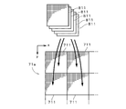
- FIG. 1 is a perspective view illustrating an appearance of a printing system. It is a bottom view of a head. It is a block diagram which shows the function structure of a control part. It is a figure which shows the flow of the process which produces printed matter. It is a figure which shows a color corrected image and a some threshold value matrix. It is a figure for demonstrating the relationship between the density of a printing image, and the maximum usage number of a lighting order.
- FIG. 1 is a perspective view showing an appearance of a printing system 1 according to an embodiment of the present invention.
- the printing system 1 performs color printing by an inkjet method on a thin plate-like or sheet-like substrate (transparent substrate) 9 having translucency, and the substrate 9 on which a color print image is formed.
- the printing system 1 in FIG. 1 includes a main body 11 and a control unit 4, and the main body 11 holds a base material 9 on the (+ Z) side surface in FIG. 1 and a stage provided on a base 20.
- a moving mechanism 22 is provided.
- a nut of a ball screw mechanism included in the stage moving mechanism 22 is fixed to the surface of the stage 21 opposite to the substrate 9, and a motor connected to the ball screw mechanism rotates, so that the stage 21 becomes Y in FIG. Moves smoothly in the direction (sub-scanning direction).
- a head 3 that discharges fine droplets of ink toward the substrate 9 is disposed.
- the head 3 is perpendicular to the sub-scanning direction by a head moving mechanism 24 having a ball screw mechanism and a motor. Is supported so as to be movable in the main scanning direction (X direction in FIG. 1) along the main surface.
- the base 20 is provided with a frame 25 so as to straddle the stage 21, and the head moving mechanism 24 is fixed to the frame 25.
- a light source 39 for emitting ultraviolet rays is provided on the frame 25, and a plurality of optical fibers (actually, the plurality of optical fibers are bundled. In FIG. The light from the light source 39 is introduced into the inside of the head 3 through the above.
- FIG. 2 is a bottom view of the head 3.
- the head 3 includes a plurality of (four in FIG. 2) nozzle units 31 that eject inks of different colors, and the plurality of nozzle units 31 are arranged in the X direction. 3 is fixed to the main body 30.
- the most (+ X) side nozzle unit 31 in FIG. 2 ejects K (black) color ink, and the ( ⁇ X) side nozzle unit 31 of the K nozzle unit 31 is C (cyan) color ink.
- the ( ⁇ X) side nozzle unit 31 of the C nozzle unit 31 ejects M (magenta) color ink, and the ( ⁇ X) side nozzle unit 31 has Y (yellow) color ink. Ink is ejected.
- the head 3 may be provided with a nozzle unit that ejects ink of other colors such as light cyan, light magenta, and white.
- each nozzle unit 31 a plurality of (for example, 300) discharge ports 311 are arranged at a constant pitch (for example, a pitch corresponding to 600 dpi (dot (per inch)) in the Y direction in FIG.
- the discharge ports 311 corresponding to each other are arranged at the same position in the Y direction.
- Each color ink contains an ultraviolet curing agent and has ultraviolet curing properties.
- oil-based ink or the like may be used.
- one or more minute droplets of the same size are continuously discharged in a short time from the discharge port 311 by one drawing control for each discharge port 311 (that is, control related to drawing of one dot). It is possible. More specifically, in the case where the head 3 continuously discharges a plurality of minute droplets in a short time, the first one of the plurality of minute droplets that is discharged first has a subsequent minute liquid due to the influence of air resistance. It is possible to make these ink droplets collide with each other during flight and land on the substrate 9 as one ink droplet by utilizing the fact that the lowering speed is lower than that of the droplet. Thereby, a dot larger than a dot formed by only one minute droplet is drawn. Actually, the time until the next drawing control is performed after one drawing control is a desired number (however, the upper limit is five in the head 3) in response to the one drawing control. It is set to a time when fine droplets can be discharged.
- the base material corresponding to the one drawing control is performed by continuously discharging one or more fine droplets from the discharge port 311 by the one drawing control for each discharge port 311.
- a dot of any size among a plurality of sizes in the present embodiment, five sizes corresponding to 1 to 5 microdroplets
- the dot size is a concept that includes not only the area of ink adhering to the substrate 9 (area corresponding to one pixel) but also the thickness of the ink.
- the value of drawing data corresponding to the ejection port 311 indicates non-drawing of dots, no dots are drawn on the substrate 9.
- the head 3 is provided with two light irradiation sections 38 connected to the light source 39 on the (+ X) side and the ( ⁇ X) side of the plurality of nozzle units 31, respectively.
- each light irradiation unit 38 a plurality of optical fibers are arranged along the Y direction, and the light irradiation unit 38 irradiates the linear region extending in the Y direction on the substrate 9 with ultraviolet rays.
- the head 3 in FIG. 1 moves in the (+ X) direction while ejecting ink, and after reaching the (+ X) side of the substrate 9, the substrate 9 moves to the ( ⁇ Y) side by a predetermined distance. It moves (that is, the head 3 performs sub-scanning relative to the substrate 9). Subsequently, the head 3 moves in the ( ⁇ X) direction while ejecting ink, and after reaching the ( ⁇ X) side of the substrate 9, the substrate 9 moves to the ( ⁇ Y) side.
- the head 3 performs main scanning relative to the base material 9 in the X direction, and each time main scanning is completed, the head 3 performs sub scanning relatively in the Y direction.
- FIG. 3 is a block diagram showing a functional configuration of the control unit 4.
- the control unit 4 includes a main body control unit 41 that performs control related to the ejection of ink from the plurality of nozzle units 31 of the head 3 and performs movement control with respect to the stage moving mechanism 22 and the head moving mechanism 24.
- the main body 11 in FIG. 1 and the main body control unit 41 in FIG. 3 function as a color printing apparatus that forms a color print image on the substrate 9.
- control unit 4 further includes data 70 (hereinafter simply referred to as “original image 70”) of a color image to be printed (that is, a set of multi-tone images of a plurality of color components, hereinafter referred to as “original image”). And the color correction (correction for color matching) performed on the original image 70 according to the print image formed on the base material 9 by the printing device.
- original image 70 a color image to be printed
- original image a set of multi-tone images of a plurality of color components
- a color correction unit 43 that obtains a multi-tone color corrected image
- a threshold matrix generation unit 44 that generates a plurality of threshold matrices for each color component, an image of each color component of the color corrected image, and a plurality of threshold values of the color component
- a halftone processing unit 45 that generates color halftone image data (hereinafter, also simply referred to as “halftone image”) used in the printing apparatus by comparing with the matrix
- An input receiving unit 46 that receives an input from the author.
- the color correction unit 43, the threshold matrix generation unit 44, the halftone processing unit 45, and the input reception unit 46 constitute an image generation device 47 that generates a color halftone image.
- an original image 70 that is generated by a predetermined method and expressed by CMYK color components is transmitted from an external computer or the like to a control unit via a predetermined network. 4 is stored in the storage unit 42. Thereby, the original image 70 is prepared in the printing system 1 (step S11).
- the original image 70 is output from the storage unit 42 to the color correction unit 43.
- the color correction unit 43 stores a color correction table for accurately expressing each color of the original image 70 (colors expressed by CMYK color components) with a print image formed on the substrate 9. Then, by performing color correction according to the color correction table on the original image 70, a color corrected image is acquired (step S12).
- the original image 70 is a set of images of a plurality of color components (CMYK color components in the present embodiment), and the color-corrected image is also a set of images of a plurality of color components.
- the color-corrected image is output to the halftone processing unit 45.
- the threshold value matrix generation unit 44 corresponds to a plurality of dot sizes for each color component in parallel with the generation of the color corrected image (may be before or after the generation of the color corrected image).
- a plurality of threshold matrixes are generated (step S13).
- the threshold matrix is a matrix in which a plurality of threshold values are arranged in the row direction and the column direction, which are the pixel arrangement directions in the color-corrected image (see FIG. 5 described later), and details of the processing in step S13 will be described later.
- the halftone processing unit 45 compares the image of each color component of the color corrected image with a plurality of threshold matrixes of the color component, thereby halftoning the color corrected image (so-called SPM (Screen (Pattern Memory). ) Method is performed), and a halftone image (halftone image) is generated (step S14).
- the halftone processing unit 45 divides the image 71a of each color component of the color-corrected image into a large number of regions having the same size, and sets a repetitive region 711 serving as a halftoning unit. .
- Each threshold matrix 811 has the same size as the repeated area 711.
- each repeated area 711 of the image 71a and a plurality of threshold matrixes 811 of the color component are overlapped, and the pixel value of each pixel in the repeated area 711
- dots of five types of sizes (hereinafter referred to as sizes 1 to 5 respectively, and the size of the dots sequentially increases from size 1 to size 5).
- Drawing is enabled, and for each color component, five threshold matrixes 811 corresponding to the dot sizes 1 to 5 are generated for determining whether or not to form dots of that size. Yes. Further, in the threshold value matrix 811 of size 1 to 5, the threshold values of the positions corresponding to each other are sequentially increased.
- the pixel value of each pixel in the image 71a of each color component of the color corrected image is compared with the corresponding threshold value of the threshold matrix 811 of size 1 to 5, and the pixel value Is larger than the (corresponding) threshold value of the threshold matrix 811 of size 5, the pixel value “5” is an image of the color component of the halftone image corresponding to the pixel (hereinafter referred to as “sub-image”). If the pixel value is greater than the threshold value of the threshold matrix 811 of size 4 and equal to or less than the threshold value of the threshold matrix 811 of size 5, the pixel value “4” corresponds to the pixel.
- Pixel value "3" is given to the position in the sub-image corresponding to the pixel.
- the pixel value “2” is a position in the sub-image corresponding to the pixel.
- the pixel value is larger than the threshold value of the threshold matrix 811 of size 1 and not larger than the threshold value of the threshold matrix 811 of size 2
- the pixel value “1” is included in the sub-image corresponding to the pixel.
- the pixel value is less than or equal to the threshold value of the threshold matrix 811 of size 1
- the pixel value “0” is assigned to the position in the sub-image corresponding to the pixel.
- a multi-valued (six-valued in this case) sub-image is generated in which each pixel is given a value of 0 indicating the absence of a dot or a value of 1 to 5 associated with the dot size, and CMYK is generated.
- a set of color component sub-images is a halftone image. In a halftone image, assuming that the color-corrected image has a uniform gradation level, the color component (sub-image) of the color-corrected image increases as the gradation level of each color component image increases.
- the expressed density that is, the average density in the area corresponding to the repeated area 711) increases.
- a process of printing the generated portion of the sub image while generating the sub image as described above is performed.
- the pixel value of the sub-image corresponding to the discharge position on the base material 9 of each discharge port 311 is “1” to “5”
- one to five small droplets are continuously ejected to the ejection position in a short time to draw one of the five sizes of dots, and the pixel value of the sub-image is “0”. In some cases, no dot is drawn at the ejection position.
- the ejection of ink from the plurality of ejection ports 311 is controlled in accordance with the sub-image of the halftone image while being synchronized with the scanning of the plurality of ejection positions on the substrate 9 respectively corresponding to the plurality of ejection ports 311. Then, a print image indicating a halftone image is formed on the substrate 9 (that is, a halftone image is printed) (step S15).
- a matrix having the same size as each threshold matrix 811 (hereinafter referred to as “basic matrix”) is prepared in advance, and all elements of the basic matrix are incremented by 1 from 0 in order.
- a lighting order number is assigned (irregularly in the present embodiment).
- the basic matrix corresponds to the threshold matrix 811 of size 1 that is the minimum size of dots
- the threshold matrix 811 of size 2 is a matrix obtained by adding the element number ⁇ of the basic matrix to the number of each element of the basic matrix.
- the threshold matrix generation unit 44 in the lighting order from 0 to (5 ⁇ -1), it is possible to change which number from 0 (hereinafter referred to as “maximum usage number”) is used for dot drawing. It has become. Specifically, an image to be halftoned has a gradation level of 0 to 255 (an image having 256 gradations (8 bits), and of course, an image having other gradation numbers).
- the lighting sequence from 0 to (5 ⁇ -1) By multiplying each number by (254 / (5 ⁇ -1)) (however, the numbers after the decimal point are rounded off), a threshold value (integer) in the range of 0 to 254 is assigned to each element of the plurality of threshold value matrices 811, and the threshold value matrix 811 is generated.
- the maximum usage number is N (where N is an integer greater than 0 and less than (5 ⁇ -1))
- each number in the lighting sequence from 0 to N is multiplied by (254 / N).
- a threshold value in the range of 0 to 254 is assigned to each element corresponding to a number from 0 to N in the plurality of threshold value matrices 811, and each element corresponding to a number from (N + 1) to (5 ⁇ 1) is assigned to each element.
- a threshold value 255 for instructing non-drawing of dots is assigned.
- FIG. 6 is a diagram for explaining the relationship between the density of the printed image and the maximum use number of the lighting order.
- the upper part of FIG. 6 shows a uniform image at the maximum gradation level 255 using the maximum use number of the lighting order used for dot drawing and a plurality of threshold matrixes generated with the maximum use number. It shows the relationship with the density of the image (printed image) printed on the substrate 9 after halftoning (the average density in the area corresponding to the repeated area 711, hereinafter referred to as “maximum printing density”).
- maximum printing density the average density in the area corresponding to the repeated area 711, hereinafter referred to as “maximum printing density”.
- . 6 shows the number of dots of each size drawn in the unit area corresponding to the repeated area 711 in the print image as the number of pixels included in the unit area (the number of positions where dots can be drawn).
- the relationship between the drawing rate of each size dot and the maximum print density is shown using the value divided by the above as the drawing rate.
- the threshold matrix generation unit 44 can change the maximum use number of the lighting order used for drawing the dots. As shown in the upper part of FIG. 6, the maximum print density increases the maximum use number. It is getting higher gradually. Here, only the relationship between the maximum usage number and the maximum printing density is shown, but actually, as the maximum usage number in the lighting order increases, a plurality of threshold value matrices generated with the maximum usage number are used.
- the maximum density value that can be expressed by a halftone image obtained by halftoning a multi-tone image (that is, when the multi-tone image is uniform at the maximum tone level 255, the repeat area 711 The average density in the corresponding region in the halftone image will also increase.
- a dot of size ⁇ ( ⁇ is any one of 1 to 5) has a pixel value of each pixel of the halftoned image larger than the threshold value of the threshold matrix 811 of size ⁇ , and , The position on the base material 9 corresponding to the pixel when the size is less than the threshold value of the threshold matrix 811 of the size ( ⁇ + 1) (however, when the size ⁇ is the maximum size, this condition is excluded). In other words, dots of different sizes are not duplicated at the same position. Therefore, as shown in the upper part of FIG. 6, for example, the maximum use number of the lighting order used for dot drawing is set to any number greater than (3 ⁇ -1) and less than (4 ⁇ -1).
- the maximum print density D3 (for example, the maximum print density at the center of the range of the maximum print density that can be realized) is set as the upper limit density for each color component of the print image.
- a plurality of threshold value matrices 811 are generated using a maximum use number that is set in advance and corresponds to the maximum print density D3.
- a halftone image is generated by using the plurality of threshold matrixes 811 in the processes of steps S ⁇ b> 14 and S ⁇ b> 15 described above, and a print image is formed on the substrate 9.
- the printed image formed on the base material 9 is confirmed by the operator as to whether or not the target color (including density) is obtained. Specifically, since the base material 9 is used for display by transmission of light from a predetermined type of light source, the color (density) of a printed image on the base material 9 that appears by transmission of light from the type of light source. And the target color (hereinafter referred to as “color shift”) is sensibly confirmed by the operator. As described above, since the color correction is performed according to the color correction table in the process of step S12 in the color correction unit 43, the color of the print image is ideally the color of the original image 70 (that is, the target and the color).
- the color correction according to the color correction table is caused by a change in temperature, humidity, light source in the installation environment of the main body 11 of the printing apparatus or a change in the state of the printing apparatus over time, There may be a color shift with respect to the original image 70 in the printed image.
- step S16 the operator inputs an upper limit density for each color component of the print image, and the input is received by the input receiving unit 46 (step S17). For example, when it is felt that one color component of the printed image on the substrate 9 that appears due to the transmission of light from the light source is thinner than the original image 70, a value higher than the maximum print density D3 is the color component. Is input as the upper limit density of the color component, and if it is felt dark, a value lower than the maximum print density D3 is input as the upper limit density of the color component.
- the threshold value matrix generation unit 44 uses the relationship between the maximum use number in the upper part of FIG. 6 and the maximum print density, and the maximum use number corresponding to the upper limit density of each color component. And a plurality of threshold matrixes of the color component are newly generated by the above method using the maximum usage number (step S13).
- each color component can be represented by a sub-image of a halftone image derived from a plurality of threshold matrixes generated with the maximum usage number as the maximum usage number of the lighting order increases. Since the maximum density value increases, the specification of the maximum usage number corresponding to the upper limit density can be regarded as determination of the maximum density value that can be expressed in the sub-image of the halftone image. Therefore, the above-described processing for generating a plurality of threshold matrixes of the color component using the maximum usage number corresponding to the upper limit density of each color component is substantially the same as that of the color component of the halftone image according to the upper limit density. The maximum density that can be expressed in an image is determined, and a plurality of threshold matrixes of the color component are generated in accordance with the maximum value.
- the halftone processing unit 45 compares the image of each color component of the color-corrected image acquired in the process of step S12 with a plurality of newly generated threshold matrixes of the color component, thereby creating a new A halftone image is generated (step S14).
- the halftone image is output to the main body control unit 41, and printing is performed on another base material 9 according to the halftone image (step S15).
- the operator confirms again whether or not the print image has the target color. If it is determined that there is no color misregistration (step S16), the substrate 9 is regarded as a printed product, and the processing in the printing system 1 is completed. If it is determined that there is a color misregistration (step S16), the operator again inputs the upper limit density of each color component of the print image, and the input is received by the input receiving unit 46 ( Step S17) After that, by performing the processes of Steps S13 to S15, a print image is formed on the substrate 9, and the presence or absence of color misregistration of the print image is determined again.
- steps S17 and S13 to S15 are repeated until it is determined that there is no color misregistration (step S16).
- step S16 In the printing system 1, when creating a plurality of printed materials for the same original image 70, printing is repeated using a halftone image when it is determined that there is no color misregistration.
- the color correction unit 43 performs color correction on the original image 70 to generate a color-corrected image, and a plurality of threshold value matrices 811 that match a preset upper limit density are displayed.
- a halftone image of the color-corrected image is generated and printed on the substrate 9.
- the threshold matrix generation unit 44 sets the density corresponding to the upper limit density to a halftone image.
- a plurality of threshold matrixes of the color component are generated so that the maximum density in the image of the color component can be expressed.
- the color correction table is not recreated by performing a complicated operation of measuring a color target indicating hundreds to thousands of tints.
- (simple) color matching can be easily performed only by adjusting the density of each color component, and a printed matter suitable for a target color (including density) can be efficiently created. .
- one or more micro droplets are continuously ejected from the ejection port 311 in a short time by one drawing control for each ejection port 311, thereby easily realizing the drawing of a plurality of sizes of dots.
- the upper limit density from the operator during the threshold matrix generation process in the first step S ⁇ b> 13 according to the translucency and color of the substrate 9 on which the print image is formed. May be accepted, and in this case, it is possible to perform preferable color matching of the printed matter in a short time.
- the lighting order in the other threshold matrix is also determined according to the basic matrix corresponding to the size 1 threshold matrix, whereby the threshold in the other threshold matrix substantially corresponds to the minimum dot size.
- the lighting order of the threshold matrix is individually determined, and the threshold values of the threshold matrix are determined according to the threshold arrangement order in the threshold matrix. The arrangement order may be different.
- the maximum printing density increases linearly as the maximum usage number increases, but if the maximum printing density gradually increases as the maximum usage number increases, the relationship between the maximum printing density and the maximum usage number. May be non-linear.
- a lighting order number may be associated with a plurality of elements of the threshold matrix so that dots of three or more sizes exist in the printed image.
- the printing system 1 may include a plateless printing apparatus (for example, an electrophotographic printing apparatus) other than the inkjet printing apparatus.
- the image generation apparatus 47 generates a threshold matrix. By changing the upper limit density at this time, simple color matching of an actual print image can be easily performed. Further, the image generation apparatus is not necessarily provided integrally with the printing apparatus, and the image generation apparatus may be provided independently of the printing apparatus.
- the printing medium in the printing system 1 may be a substrate having a dark color, a printing paper, a film, or the like in addition to the substrate 9 having translucency.
Landscapes
- Physics & Mathematics (AREA)
- Discrete Mathematics (AREA)
- General Physics & Mathematics (AREA)
- Engineering & Computer Science (AREA)
- Multimedia (AREA)
- Signal Processing (AREA)
- Health & Medical Sciences (AREA)
- General Health & Medical Sciences (AREA)
- Toxicology (AREA)
- Color, Gradation (AREA)
- Facsimile Image Signal Circuits (AREA)
- Color Image Communication Systems (AREA)
Abstract
色補正部(43)では、複数サイズのドットの描画が可能な印刷装置により形成される印刷画像に合わせた色補正を元画像(70)に対して施して色補正済み画像が取得され、ハーフトーン処理部(45)では、色補正済み画像の各色成分の画像とドットの複数サイズに対応する複数の閾値マトリクスとを比較することにより、ハーフトーン画像が生成される。印刷物を作成する際には、印刷画像の各色成分における上限濃度の入力が受け付けられ、閾値マトリクス生成部(44)では、上限濃度に合わせてハーフトーン画像の各色成分の画像にて表現可能な濃度の最大値が決定され、この最大値に合わせてハーフトーン処理部(45)にて用いられる複数の閾値マトリクスが生成される。これにより、印刷装置にて色ずれが生じている場合でも、各色成分の上限濃度の変更による印刷画像の(簡易な)カラーマッチングが容易に実現される。
Description
本発明は、ハーフトーン画像を生成する画像生成装置、および、印刷画像を印刷媒体上に形成する印刷システムに関する。
従来より、オフセット印刷等の刷版を用いた有版印刷が行われており、所望の色を表現する印刷物を作成するために、各色の刷版の作製時にトーンカーブ補正やカラーマッチング処理が行われる。近年では、インクジェット方式の印刷装置等、刷版を用いない無版印刷装置にて、多品種かつ少量の印刷物を作成することも行われつつあり、製版工程が不要な無版印刷は、多品種少量生産における生産性やコスト面の優位性を有している。
無版印刷装置において印刷画像を目標(ターゲット)とする色に合わせるカラーマッチングとして様々な手法が提案されており、例えば、特開平11-164162号公報(文献1)では、色標が配置された標準原稿をカラースキャナで読み取ることにより、カラースキャナの色補正参照テーブルを求め、カラースキャナの色補正参照テーブルに基づいて補正された標準原稿の画像データをカラープリンタで印画し、その印画結果をカラースキャナで読み取ることにより、カラープリンタの色補正参照テーブルを求めて、カラープリンタとカラースキャナとの間のカラーマッチングを行う手法が開示されている。
また、特開2002-290756号公報(文献2)では、複数のカラー出力機とクライアントとの間に介在してカラーマッチングサービスを提供する装置が開示されており、この装置では、各カラー出力機に対する測色データが取得され、ターゲット出力機の指定と、実際の出力処理を行う出力機の特性情報とを含む印刷条件をクライアントから受け付けた際に、当該出力機でのカラー再現状態をターゲット出力機でのカラー再現状態にマッチングさせるためのカラープロファイルデータがクライアントに提供される。
一方で、インクジェット方式の印刷では、近年、各吐出口に対する一の描画制御にて複数サイズのうちのいずれかのサイズのドットが描画可能なヘッド(すなわち、多値制御が可能なヘッド)が実用化されている。このようなヘッドとしては、吐出口から1以上の同サイズの微小液滴を短時間に連続的に吐出する方式のものや、駆動信号の波形や電圧を変調することにより吐出口から吐出される微小液滴の量を変更する方式のものが知られており、いずれの方式においても広範囲の印刷濃度(ベタ濃度)の再現が可能とされる。なお、特開2004-9548号公報では、小質量のインク液滴の吐出と、大質量のインク液滴の吐出とを組み合わせて1画素の印字を行うインクジェットプリンタが開示されている。
ところで、文献1または2の手法を用いて適切なカラーマッチングを行う場合でも、印刷装置の状態の経時変化により色がずれてくることがあり、色ずれが生じる度に、数百~数千のチントを示す色標を測定する煩雑な作業が必要となる。特に、インクジェット方式の印刷装置では、設置環境における温度や湿度の変化により印刷画像のトーンが変わりやすく、カラーマッチングに係る作業が必要となる頻度が高くなる。
本発明は複数サイズのドットの描画が可能なカラーの印刷装置にて用いられるハーフトーン画像を生成する画像生成装置に向けられており、印刷画像のカラーマッチングを容易に行うことを目的としている。
本発明に係る画像生成装置は、前記印刷装置により印刷媒体上に形成される印刷画像に合わせた色補正を元画像に対して施して色補正済み画像を取得する色補正部と、前記色補正済み画像の各色成分の画像とドットの前記複数サイズに対応する複数の閾値マトリクスとを比較することにより、前記各色成分の前記画像の階調レベルの増大に従って前記各色成分において表現される濃度が増大するハーフトーン画像を生成するハーフトーン処理部と、印刷画像の前記各色成分における上限濃度の入力を受け付ける入力受付部と、前記上限濃度に合わせてハーフトーン画像の前記各色成分の画像にて表現可能な濃度の最大値を決定し、前記最大値に合わせて前記複数の閾値マトリクスを生成する閾値マトリクス生成部とを備える。本発明によれば、色補正テーブルを再作成することなく、実際の印刷画像の(簡易な)カラーマッチングを容易に行うことができる。
本発明の一の好ましい実施の形態では、前記印刷装置が、インクの微小液滴を印刷媒体に向けて吐出する複数の吐出口を有する。より好ましくは、前記印刷装置において、各吐出口に対する一の描画制御にて前記各吐出口から1以上の微小液滴を短時間に連続的に吐出することにより、または、前記一の描画制御にて前記各吐出口から吐出される微小液滴の量を変更することにより、前記一の描画制御に対応する印刷媒体上の位置に前記複数サイズのいずれかのドットが描画可能とされる。これにより、複数サイズのドットの描画を容易に行うことができる。
本発明の他の好ましい実施の形態では、前記閾値マトリクス生成部において、ドットの最小サイズに対応する閾値マトリクスにおける閾値の配置順序に従って、他の閾値マトリクスにおける閾値が決定されることにより、複数の閾値マトリクスを容易に生成することができる。
本発明のさらに他の好ましい実施の形態では、前記印刷画像が形成された前記印刷媒体が、光の透過による表示に利用されるものである。これにより、測色が困難な透過による表示に利用される印刷媒体において、カラーマッチングを容易に行うことができる。
本発明は、カラーの印刷画像を印刷媒体上に形成する印刷システムにも向けられている。印刷システムは、元画像からハーフトーン画像を生成する画像生成装置と、印刷媒体上に複数サイズのドットの描画が可能とされ、前記ハーフトーン画像に従って印刷媒体に印刷を行う印刷装置とを備え、前記画像生成装置が、前記印刷装置により印刷媒体上に形成される印刷画像に合わせた色補正を元画像に対して施して色補正済み画像を取得する色補正部と、前記色補正済み画像の各色成分の画像とドットの前記複数サイズに対応する複数の閾値マトリクスとを比較することにより、前記各色成分の前記画像の階調レベルの増大に従って前記各色成分において表現される濃度が増大するハーフトーン画像を生成するハーフトーン処理部と、印刷画像の前記各色成分における上限濃度の入力を受け付ける入力受付部と、前記上限濃度に合わせてハーフトーン画像の前記各色成分の画像にて表現可能な濃度の最大値を決定し、前記最大値に合わせて前記複数の閾値マトリクスを生成する閾値マトリクス生成部とを備える。これにより、色補正テーブルを再作成することなく、実際の印刷画像の(簡易な)カラーマッチングを容易に行うことができる。
上述の目的および他の目的、特徴、態様および利点は、添付した図面を参照して以下に行うこの発明の詳細な説明により明らかにされる。
図1は本発明の一の実施の形態に係る印刷システム1の外観を示す斜視図である。印刷システム1は、透光性を有する薄い板状またはシート状の基材(透過基材)9上にインクジェット方式にてカラー印刷を行うものであり、カラーの印刷画像が形成された基材9は、光の透過による各種表示(サインディスプレイ等)に利用される。
図1の印刷システム1は本体11および制御部4を備え、本体11は基材9を図1中の(+Z)側の面上に保持するステージ21、および、基台20上に設けられるステージ移動機構22を備える。ステージ21の基材9とは反対側の面には、ステージ移動機構22が有するボールネジ機構のナットが固定され、ボールネジ機構に接続されたモータが回転することにより、ステージ21が図1中のY方向(副走査方向)に滑らかに移動する。
ステージ21の上方には基材9に向けてインクの微小液滴を吐出するヘッド3が配置され、ヘッド3は、ボールネジ機構およびモータを有するヘッド移動機構24により副走査方向に垂直かつ基材9の主面に沿う主走査方向(図1中のX方向)に移動可能に支持される。また、基台20には、ステージ21を跨ぐようにしてフレーム25が設けられ、ヘッド移動機構24はフレーム25に固定される。フレーム25上には紫外線を出射する光源39が設けられ、複数の光ファイバ(実際には、複数の光ファイバは束状となっており、図1では符号391を付して1本の太線にて示している。)を介して光源39からの光がヘッド3の内部へと導入される。
図2はヘッド3の底面図である。図2に示すように、ヘッド3はそれぞれが互いに異なる色のインクを吐出する複数の(図2では、4個の)ノズルユニット31を備え、複数のノズルユニット31はX方向に配列されてヘッド3の本体30に固定される。図2中の最も(+X)側のノズルユニット31はK(ブラック)の色のインクを吐出し、Kのノズルユニット31の(-X)側のノズルユニット31はC(シアン)の色のインクを吐出し、Cのノズルユニット31の(-X)側のノズルユニット31はM(マゼンタ)の色のインクを吐出し、最も(-X)側のノズルユニット31はY(イエロー)の色のインクを吐出する。もちろん、ヘッド3には、ライトシアン、ライトマゼンタ、ホワイト等の他の色のインクを吐出するノズルユニットが設けられてもよい。
各ノズルユニット31では、図2中のY方向に複数の(例えば、300個の)吐出口311が一定のピッチ(例えば、600dpi(dot per inch)に相当するピッチ)にて配列されており、複数のノズルユニット31において、互いに対応する吐出口311はY方向の同じ位置に配置される。また、各色のインクは紫外線硬化剤を含んでおり、紫外線硬化性を有している。印刷システム1では、油性のインク等が用いられてもよい。
ヘッド3では、各吐出口311に対する一の描画制御(すなわち、1つのドットの描画に係る制御)にて当該吐出口311から1以上の同サイズの微小液滴を短時間に連続的に吐出することが可能とされる。詳細には、ヘッド3では、複数の微小液滴を短時間に連続的に吐出する場合に、当該複数の微小液滴のうち最初に吐出されたものにおいて、空気抵抗の影響により後続の微小液滴よりも降下速度が低くなることを利用して、飛翔中にこれらのインクの微小液滴を互いに衝突させ、基材9上に1つのインクの液滴として着弾させることが可能となっており、これにより、1つの微小液滴のみにて形成されるドットよりも大きなドットが描画される。実際には、一の描画制御の後、次の描画制御を行うまでの時間は、当該一の描画制御に応答して所望の個数(ただし、ヘッド3では5個が上限とされる。)の微小液滴の吐出が可能な時間に設定されている。
このように、印刷システム1では、各吐出口311に対する一の描画制御にて当該吐出口311から1以上の微小液滴を連続的に吐出することにより、当該一の描画制御に対応する基材9上の位置に複数サイズ(本実施の形態では、1ないし5個の微小液滴にそれぞれ対応する5種類のサイズ)のうちのいずれかのサイズのドットが描画可能となっている。ここで、ドットのサイズは、基材9上に付着したインクの面積(1画素に対応する面積)のみならず、当該インクの厚さも含む概念となっている。なお、当該吐出口311に対応する描画データの値(後述のハーフトーン画像の値)がドットの非描画を示す場合には、基材9上にドットは描画されない。
また、ヘッド3には、光源39に接続される2つの光照射部38が複数のノズルユニット31の(+X)側および(-X)側にそれぞれ設けられる。各光照射部38では、複数の光ファイバがY方向に沿って配列されており、基材9上においてY方向に伸びる線状の領域に光照射部38により紫外線が照射される。
実際の印刷時には、図1のヘッド3がインクを吐出しつつ(+X)方向に移動し、基材9の(+X)側へと到達した後に基材9が(-Y)側に所定距離だけ移動する(すなわち、ヘッド3が基材9に対して相対的に副走査する。)。続いて、ヘッド3がインクを吐出しつつ(-X)方向に移動し、基材9の(-X)側へと到達した後に基材9が(-Y)側に移動する。このように、印刷システム1ではヘッド3が基材9に対してX方向に相対的に主走査するとともに、主走査が完了する毎に、Y方向に相対的に副走査する。
図3は制御部4の機能構成を示すブロック図である。図3に示すように制御部4は、ヘッド3の複数のノズルユニット31からのインクの吐出に係る制御、並びに、ステージ移動機構22およびヘッド移動機構24に対する移動制御を行う本体制御部41を備える。印刷システム1では、図1の本体11および図3の本体制御部41が、カラーの印刷画像を基材9上に形成するカラーの印刷装置として機能する。
制御部4は、さらに、印刷対象のカラーの画像(すなわち、複数の色成分の多階調画像の集合であり、以下、「元画像」という。)のデータ70(以下、単に「元画像70」ともいう。)を記憶する記憶部42、印刷装置により基材9上に形成される印刷画像に合わせた色補正(色合わせ(カラーマッチング)のための補正)を元画像70に対して施して多階調の色補正済み画像を取得する色補正部43、各色成分において複数の閾値マトリクスを生成する閾値マトリクス生成部44、色補正済み画像の各色成分の画像と当該色成分の複数の閾値マトリクスとを比較することにより、印刷装置にて用いられるカラーのハーフトーン画像のデータ(以下、単に「ハーフトーン画像」ともいう。)を生成するハーフトーン処理部45、並びに、操作者からの入力を受け付ける入力受付部46を備える。印刷システム1では、色補正部43、閾値マトリクス生成部44、ハーフトーン処理部45および入力受付部46により、カラーのハーフトーン画像を生成する画像生成装置47が構築されている。
次に、印刷システム1において基材9上に印刷画像を形成して印刷物を作成する処理について図4を参照しつつ説明する。印刷システム1にて印刷が行われる際には、まず、所定の手法にて生成されるとともにCMYK色成分にて表現される元画像70が、外部のコンピュータ等から所定のネットワークを介して制御部4の記憶部42に入力されて記憶される。これにより、印刷システム1にて元画像70が準備される(ステップS11)。
続いて、元画像70が記憶部42から色補正部43に出力される。色補正部43では、元画像70の各色(CMYK色成分にて表現される色)を、基材9上に形成される印刷画像にて正確に表現するための色補正テーブルが記憶されており、元画像70に対して色補正テーブルに従った色補正を施すことにより、色補正済み画像が取得される(ステップS12)。既述のように、元画像70は複数の色成分(本実施の形態では、CMYK色成分)の画像の集合であり、色補正済み画像も複数の色成分の画像の集合となっている。色補正済み画像はハーフトーン処理部45に出力される。
一方で、閾値マトリクス生成部44では、色補正済み画像の生成に並行して(色補正済み画像の生成前または後であってもよい。)、各色成分に対してドットの複数サイズにそれぞれ対応する複数の閾値マトリクスが生成される(ステップS13)。閾値マトリクスは、色補正済み画像における画素の配列方向である行方向および列方向に複数の閾値が配列されたものであり(後述の図5参照)、ステップS13の処理の詳細については後述する。ハーフトーン処理部45では、色補正済み画像の各色成分の画像と、当該色成分の複数の閾値マトリクスとを比較することにより、色補正済み画像がハーフトーン化され(いわゆる、SPM(Screen Pattern Memory)方式による網掛け処理が行われ)、ハーフトーン画像(網点画像)が生成される(ステップS14)。
ここで、色補正済み画像のハーフトーン化について説明する。ハーフトーン処理部45では、図5に示すように色補正済み画像の各色成分の画像71aを同一の大きさの多数の領域に分割してハーフトーン化の単位となる繰り返し領域711が設定される。各閾値マトリクス811は繰り返し領域711と同じサイズとされ、概念的には画像71aの各繰り返し領域711と当該色成分の複数の閾値マトリクス811とを重ね合わせ、繰り返し領域711の各画素の画素値と複数の閾値マトリクス811の対応する閾値とが比較されることにより、基材9上のその画素の位置に当該色成分のいずれのサイズのドットを描画するか、または、ドットを描画しないかが決定される。
本実施の形態では、既述のように5種類のサイズ(以下、それぞれサイズ1ないし5と表現し、サイズ1からサイズ5に向かって順にドットのサイズが大きくなるものとする。)のドットの描画が可能とされており、各色成分に対してドットのサイズ1ないし5にそれぞれ対応する5個の閾値マトリクス811が、当該サイズのドットの形成の要否を決定するためのものとして生成されている。また、サイズ1ないし5の閾値マトリクス811では、互いに対応する位置の閾値が順に大きくなっている。
実際のハーフトーン画像の生成では、既述のように、色補正済み画像の各色成分の画像71aにおける各画素の画素値がサイズ1ないし5の閾値マトリクス811の対応する閾値と比較され、画素値がサイズ5の閾値マトリクス811の(対応する)閾値よりも大きい場合には、画素値「5」が当該画素に対応するハーフトーン画像の当該色成分の画像(以下、「サブ画像」という。)中の位置に付与され、画素値がサイズ4の閾値マトリクス811の閾値よりも大きく、かつ、サイズ5の閾値マトリクス811の閾値以下である場合には、画素値「4」が当該画素に対応するサブ画像中の位置に付与され、画素値がサイズ3の閾値マトリクス811の閾値よりも大きく、かつ、サイズ4の閾値マトリクス811の閾値以下である場合には、画素値「3」が当該画素に対応するサブ画像中の位置に付与される。また、画素値がサイズ2の閾値マトリクス811の閾値よりも大きく、かつ、サイズ3の閾値マトリクス811の閾値以下である場合には、画素値「2」が当該画素に対応するサブ画像中の位置に付与され、画素値がサイズ1の閾値マトリクス811の閾値よりも大きく、かつ、サイズ2の閾値マトリクス811の閾値以下である場合には、画素値「1」が当該画素に対応するサブ画像中の位置に付与され、画素値がサイズ1の閾値マトリクス811の閾値以下である場合には、画素値「0」が当該画素に対応するサブ画像中の位置に付与される。
このようにして、各画素にドットの不存在を示す値0またはドットのサイズに対応付けられた値1~5が付与された多値の(ここでは6値の)サブ画像が生成され、CMYK色成分のサブ画像の集合がハーフトーン画像とされる。ハーフトーン画像では、色補正済み画像が一様な階調レベルを有すると仮定した場合に、色補正済み画像の各色成分の画像の階調レベルの増大に従って、当該色成分(のサブ画像)において表現される濃度(すなわち、繰り返し領域711に対応する領域における平均濃度)が増大することとなる。
印刷システム1では、各色成分に関して、上記のようにしてサブ画像を生成しつつ、サブ画像の生成された部分を印刷する処理が行われる。具体的には、ヘッド3の基材9に対する相対移動に同期して、各吐出口311の基材9上の吐出位置に対応するサブ画像の画素値が「1」ないし「5」である場合には当該吐出位置に対して1ないし5個の微小液滴を短時間に連続的に吐出することにより5種類のサイズのいずれかのドットが描画され、サブ画像の画素値が「0」である場合には当該吐出位置にはドットは描画されない。このようにして、複数の吐出口311にそれぞれ対応する基材9上の複数の吐出位置の走査に同期しつつ、ハーフトーン画像のサブ画像に従って、複数の吐出口311からのインクの吐出が制御され、基材9上にハーフトーン画像を示す印刷画像が形成される(すなわち、ハーフトーン画像が印刷される。)(ステップS15)。
ここで、ステップS13における閾値マトリクス生成部44による閾値マトリクス811の生成処理について説明する。以下の説明では、一の色成分のみに着目するが、他の色成分においても同様の処理が行われる。
閾値マトリクス生成部44では、各閾値マトリクス811と同じ大きさのマトリクス(以下、「基礎マトリクス」という。)が予め準備されており、基礎マトリクスの全ての要素には、0から順に1ずつ増加する点灯順序の番号が(本実施の形態では、不規則に)付与されている。基礎マトリクスは、ドットの最小サイズであるサイズ1の閾値マトリクス811に対応するものとされ、サイズ2の閾値マトリクス811には、基礎マトリクスの各要素の番号に基礎マトリクスの要素数αを加算したマトリクスが設定され、サイズ3ないし5の閾値マトリクス811には、基礎マトリクスの要素数αを2ないし4倍した値を基礎マトリクスの各要素の番号に加算したマトリクスがそれぞれ設定される。したがって、サイズ1ないし5の閾値マトリクス811の全ての要素には、0から(5α-1)までのいずれかの番号が関連付けられるとともに、各閾値マトリクス811内での番号の順序は、全ての閾値マトリクス811において同一となる。
また、閾値マトリクス生成部44では、0から(5α-1)までの点灯順序において、0からいずれの番号(以下、「最大利用番号」という。)までをドットの描画に利用するかが変更可能となっている。具体的には、ハーフトーン化される画像が0~255の階調レベル(256階調(8bit)の画像であり、もちろん、他の階調数を有する画像であってもよい。)を有している場合に、最大利用番号を(5α-1)とする(すなわち、0から(5α-1)までの全ての番号を利用する)ときには、0から(5α-1)までの点灯順序の各番号を(254/(5α-1))倍することにより(ただし、小数点以下は四捨五入)、0~254の範囲の閾値(整数)が複数の閾値マトリクス811の各要素に割り当てられ、閾値マトリクス811が生成される。また、最大利用番号をN(ただし、Nは0よりも大きく、かつ、(5α-1)未満の整数)とするときには、0からNまでの点灯順序の各番号を(254/N)倍することにより、0~254の範囲の閾値が複数の閾値マトリクス811における0からNまでの番号に対応する各要素に割り当てられ、(N+1)から(5α-1)までの番号に対応する各要素には、例えば、ドットの非描画を指示する閾値255が割り当てられる。
図6は、印刷画像の濃度と点灯順序の最大利用番号との関係を説明するための図である。図6の上段は、ドットの描画に利用する点灯順序の最大利用番号と、当該最大利用番号にて生成された複数の閾値マトリクスを用いて、最大の階調レベル255にて一様な画像をハーフトーン化して基材9上に印刷した画像(印刷画像)の濃度(繰り返し領域711に対応する領域での平均濃度であり、以下、「最大印刷濃度」という。)との関係を示している。また、図6の下段は、当該印刷画像において繰り返し領域711に対応する単位領域内に描画される各サイズのドットの個数を単位領域に含まれる画素数(ドットが描画可能な位置の数)にて除算した値を描画率として、各サイズのドットの描画率と最大印刷濃度との関係を示しており、図6の下段では符号L1~L5を付す線にてサイズ1ないし5のドットの描画率をそれぞれ示している。
既述のように、閾値マトリクス生成部44ではドットの描画に利用する点灯順序の最大利用番号が変更可能となっており、図6の上段に示すように、最大印刷濃度は最大利用番号の増大に従って漸次高くなっている。ここでは、最大利用番号と最大印刷濃度との関係のみが示されているが、実際には、点灯順序の最大利用番号の増大に従って、当該最大利用番号にて生成された複数の閾値マトリクスを用いて多階調画像をハーフトーン化したハーフトーン画像にて表現可能な濃度の最大値(すなわち、当該多階調画像が最大の階調レベル255にて一様である場合に、繰り返し領域711に対応するハーフトーン画像中の領域における平均濃度)も増大することとなる。
また、既述のように、サイズβ(βは1ないし5のいずれか)のドットは、ハーフトーン化される画像の各画素の画素値がサイズβの閾値マトリクス811の閾値よりも大きく、かつ、サイズ(β+1)の閾値マトリクス811の閾値以下(ただし、サイズβが最大サイズである場合には、この条件は除外される。)である場合に、当該画素に対応する基材9上の位置に描画され、同位置に異なるサイズのドットが重複して描画されることはない。したがって、図6の上段に示すように、例えば、ドットの描画に利用する点灯順序の最大利用番号が(3α-1)よりも大きく、かつ、(4α-1)未満のいずれかの番号とされ、最大印刷濃度がD1よりも大きく、かつ、D2未満のいずれかの値とされる場合には、図6の下段に示すように、最大の階調レベルにて一様な画像に対応する印刷画像ではサイズ3および4のドットのみが存在することとなる。なお、最大利用番号が0よりも大きく、かつ、(α-1)以下のいずれかの番号とされる場合には、印刷画像にはサイズ1のドットのみが存在することとなる。図6の上段に示す最大利用番号と最大印刷濃度との関係は、実験等により予め取得され、閾値マトリクス生成部44にて記憶される。
本実施の形態における上述の(最初の)ステップS13の処理では、印刷画像の各色成分に対する上限濃度として最大印刷濃度D3(例えば、実現可能な最大印刷濃度の範囲のおよそ中央の最大印刷濃度)が予め設定されており、最大印刷濃度D3に対応する最大利用番号を用いて複数の閾値マトリクス811が生成される。そして、既述のステップS14,S15の処理にて、当該複数の閾値マトリクス811を用いてハーフトーン画像が生成され、基材9上に印刷画像が形成されている。
基材9上に形成された印刷画像は、操作者により目標とする色(濃度を含む。)となっているか否かが確認される。具体的には、基材9は、所定の種類の光源からの光の透過による表示に利用されるため、当該種類の光源からの光の透過により現れる基材9上の印刷画像の色(濃度を含む。)と、目標とする色とのずれ(以下、「色ずれ」という。)が許容範囲内であるか否かが操作者により感覚的に確認される。既述のように、色補正部43におけるステップS12の処理では、色補正テーブルに従って色補正が行われているため、理想的には、印刷画像の色は元画像70の色(すなわち、目標とする色)に一致しているが、印刷装置の本体11の設置環境における温度や湿度、光源の変化、あるいは、印刷装置の状態の経時変化により色補正テーブルに従った色補正にずれが生じ、印刷画像において元画像70に対する色ずれが発生している場合がある。
色ずれがあると判断される場合には(ステップS16)、操作者により印刷画像の各色成分における上限濃度の入力が行われて、当該入力が入力受付部46にて受け付けられる(ステップS17)。例えば、光源からの光の透過により現れる基材9上の印刷画像の一の色成分が、元画像70に比べて薄いと感じられる場合には、最大印刷濃度D3よりも高い値が当該色成分の上限濃度として入力され、濃いと感じられる場合には、最大印刷濃度D3よりも低い値が当該色成分の上限濃度として入力される。
色成分毎の上限濃度の入力が受け付けられると、閾値マトリクス生成部44では、図6の上段の最大利用番号と最大印刷濃度との関係を用いて、各色成分の上限濃度に対応する最大利用番号が特定され、当該最大利用番号を用いて上記手法により当該色成分の複数の閾値マトリクスが新たに生成される(ステップS13)。
ここで、既述のように、各色成分において、点灯順序の最大利用番号の増大に従って、当該最大利用番号にて生成された複数の閾値マトリクスから導かれるハーフトーン画像のサブ画像にて表現可能な濃度の最大値が増大するため、上限濃度に対応する最大利用番号の特定は、ハーフトーン画像のサブ画像にて表現可能な濃度の最大値の決定と捉えることができる。したがって、各色成分の上限濃度に対応する最大利用番号を用いて当該色成分の複数の閾値マトリクスを生成する上記処理は、実質的には、当該上限濃度に合わせてハーフトーン画像の当該色成分の画像にて表現可能な濃度の最大値を決定し、当該最大値に合わせて当該色成分の複数の閾値マトリクスを生成する処理となる。
ハーフトーン処理部45では、上記ステップS12の処理にて取得された色補正済み画像の各色成分の画像と、新たに生成された当該色成分の複数の閾値マトリクスとを比較することにより、新たなハーフトーン画像が生成される(ステップS14)。ハーフトーン画像は本体制御部41に出力され、ハーフトーン画像に従って別の基材9に印刷が行われる(ステップS15)。
基材9上への印刷画像の形成が完了すると、印刷画像が目標とする色となっているか否かが操作者により再度確認される。そして、色ずれがないと判断される場合には(ステップS16)、当該基材9が印刷物の完成品とされ、印刷システム1における処理が完了する。また、色ずれがあると判断される場合には(ステップS16)、操作者により印刷画像の各色成分における上限濃度の再度の入力が行われて、当該入力が入力受付部46にて受け付けられ(ステップS17)、その後、ステップS13~S15の処理を行うことにより基材9上に印刷画像が形成されて、当該印刷画像の色ずれの有無が再度判断される。このようにして、色ずれがないと判断されるまで、ステップS17,S13~S15の処理が繰り返される(ステップS16)。なお、印刷システム1では、同じ元画像70に対する複数の印刷物を作成する際には、色ずれがないと判断された際のハーフトーン画像を用いて印刷が繰り返される。
以上に説明したように、印刷システム1では、色補正部43にて元画像70に対する色補正を行って色補正済み画像が生成され、予め設定される上限濃度に合わせた複数の閾値マトリクス811を用いて色補正済み画像のハーフトーン画像が生成され、基材9上に印刷される。そして、操作者が印刷画像を確認(検査)することにより、次の印刷画像の各色成分における上限濃度の入力が行われ、閾値マトリクス生成部44において、当該上限濃度に合わせた濃度がハーフトーン画像の当該色成分の画像における最大濃度として表現可能となるように、当該色成分の複数の閾値マトリクスが生成される。これにより、印刷装置の状態の経時変化等により色ずれが生じている場合に、数百~数千のチントを示す色標を測定する煩雑な作業を行って色補正テーブルを再作成することなく、実際の印刷画像において、各色成分の濃度調整のみによる(簡易な)カラーマッチングを容易に行うことができ、目標とする色(濃度を含む。)に合った印刷物を効率よく作成することができる。
また、光の透過による表示に利用される基材9では、照明用の光源の輝度や照明光の波長帯によって測色値がばらつくため、正確な測色が困難であるが(すなわち、正確なカラーマッチングが容易ではないが)、印刷システム1では、操作者が上限濃度を入力して実際の印刷画像(印刷物)における各色成分の濃度調整を感覚的に行うことにより、印刷画像の(簡易な)カラーマッチングが容易に実現される。さらに、同じ元画像70を他の種類の基材に印刷する場合でも、当該基材に合わせた上限濃度の変更(すなわち、濃度調整)のみにより、カラーマッチングを効率的に行うことができる。
以上、本発明の実施の形態について説明してきたが、本発明は上記実施の形態に限定されるものではなく、様々な変形が可能である。
上記実施の形態では、各吐出口311に対する一の描画制御にて当該吐出口311から1以上の微小液滴を短時間に連続的に吐出することにより複数サイズのドットの描画が容易に実現されるが、印刷システム1では、一の描画制御にて各吐出口311から吐出される微小液滴の量(一の微小液滴の量)を変更することにより、複数サイズのドットの描画が容易に実現されてもよい。
図4に示す印刷物の作成処理では、印刷画像が形成される基材9の透光性や色等に応じて、最初のステップS13における閾値マトリクスの生成処理の際に、操作者からの上限濃度の入力が受け付けられてもよく、この場合、印刷物の好ましい色合わせを短時間にて行うことが可能となる。
上記実施の形態では、サイズ1の閾値マトリクスに対応する基礎マトリクスに従って、他の閾値マトリクスにおける点灯順序も決定されることにより、当該他の閾値マトリクスにおける閾値が、実質的にドットの最小サイズに対応する閾値マトリクスにおける閾値の配置順序に従って決定され、複数の閾値マトリクスが容易に生成されるが、印刷システム1の設計によっては、閾値マトリクスの点灯順序が個別に決定され、複数の閾値マトリクスにおいて閾値の配置順序が相違していてもよい。
図6の上段では、最大印刷濃度が最大利用番号の増大に従って線形に上昇するが、最大印刷濃度が最大利用番号の増大に従って漸次高くなるのであるならば、最大印刷濃度と最大利用番号との関係は非線形であってもよい。また、図6の下段では、各最大印刷濃度において、最大の階調レベルにて一様な画像に対応する印刷画像中に1または2種類のサイズのドットのみが存在することとなるが、当該印刷画像中に3種類以上のサイズのドットが存在するように、複数の閾値マトリクスの要素に点灯順序の番号が関連付けられてもよい。
印刷システム1は、インクジェット方式の印刷装置以外の無版印刷装置(例えば、電子写真方式の印刷装置)を有するものであってもよく、この場合も、画像生成装置47において、閾値マトリクスを生成する際の上限濃度を変更することにより、実際の印刷画像の簡易なカラーマッチングを容易に行うことが可能となる。また、画像生成装置は、必ずしも印刷装置と一体的に設けられる必要はなく、画像生成装置が印刷装置から独立して設けられてもよい。
印刷システム1における印刷媒体は、透光性を有する基材9以外に、濃い色を有する基材、あるいは、印刷用紙やフィルム等であってもよい。
この発明を詳細に描写して説明したが、既述の説明は例示的であって限定的なものではない。したがって、この発明の範囲を逸脱しない限り、多数の変形や態様が可能であることが理解される。
Claims (8)
- 複数サイズのドットの描画が可能なカラーの印刷装置(11,41)にて用いられるハーフトーン画像を生成する画像生成装置(47)であって、
前記印刷装置により印刷媒体(9)上に形成される印刷画像に合わせた色補正を元画像(70)に対して施して色補正済み画像を取得する色補正部(43)と、
前記色補正済み画像の各色成分の画像(71a)とドットの前記複数サイズに対応する複数の閾値マトリクス(811)とを比較することにより、前記各色成分の前記画像の階調レベルの増大に従って前記各色成分において表現される濃度が増大するハーフトーン画像を生成するハーフトーン処理部(45)と、
印刷画像の前記各色成分における上限濃度の入力を受け付ける入力受付部(46)と、
前記上限濃度に合わせてハーフトーン画像の前記各色成分の画像にて表現可能な濃度の最大値を決定し、前記最大値に合わせて前記複数の閾値マトリクスを生成する閾値マトリクス生成部(44)と、
を備える。 - 請求項1に記載の画像生成装置であって、
前記印刷装置が、インクの微小液滴を印刷媒体に向けて吐出する複数の吐出口(311)を有する。 - 請求項2に記載の画像生成装置であって、
前記印刷装置において、各吐出口に対する一の描画制御にて前記各吐出口から1以上の微小液滴を短時間に連続的に吐出することにより、または、前記一の描画制御にて前記各吐出口から吐出される微小液滴の量を変更することにより、前記一の描画制御に対応する印刷媒体上の位置に前記複数サイズのいずれかのドットが描画可能とされる。 - 請求項1ないし3のいずれかに記載の画像生成装置であって、
前記閾値マトリクス生成部において、ドットの最小サイズに対応する閾値マトリクスにおける閾値の配置順序に従って、他の閾値マトリクスにおける閾値が決定される。 - 請求項1ないし4のいずれかに記載の画像生成装置であって、
前記印刷画像が形成された前記印刷媒体が、光の透過による表示に利用されるものである。 - カラーの印刷画像を印刷媒体(9)上に形成する印刷システム(1)であって、
元画像(70)からハーフトーン画像を生成する画像生成装置(47)と、
印刷媒体上に複数サイズのドットの描画が可能とされ、前記ハーフトーン画像に従って印刷媒体に印刷を行う印刷装置(11,41)と、
を備え、
前記画像生成装置が、
前記印刷装置により印刷媒体上に形成される印刷画像に合わせた色補正を元画像に対して施して色補正済み画像を取得する色補正部(43)と、
前記色補正済み画像の各色成分の画像(71a)とドットの前記複数サイズに対応する複数の閾値マトリクス(811)とを比較することにより、前記各色成分の前記画像の階調レベルの増大に従って前記各色成分において表現される濃度が増大するハーフトーン画像を生成するハーフトーン処理部(45)と、
印刷画像の前記各色成分における上限濃度の入力を受け付ける入力受付部(46)と、
前記上限濃度に合わせてハーフトーン画像の前記各色成分の画像にて表現可能な濃度の最大値を決定し、前記最大値に合わせて前記複数の閾値マトリクスを生成する閾値マトリクス生成部(44)と、
を備える。 - 請求項6に記載の印刷システムであって、
前記印刷装置が、インクの微小液滴を印刷媒体に向けて吐出する複数の吐出口(311)を有する。 - 請求項7に記載の印刷システムであって、
前記印刷装置において、各吐出口に対する一の描画制御にて前記各吐出口から1以上の微小液滴を短時間に連続的に吐出することにより、または、前記一の描画制御にて前記各吐出口から吐出される微小液滴の量を変更することにより、前記一の描画制御に対応する印刷媒体上の位置に前記複数サイズのいずれかのドットが描画可能とされる。
Applications Claiming Priority (2)
| Application Number | Priority Date | Filing Date | Title |
|---|---|---|---|
| JP2008245615A JP2010081180A (ja) | 2008-09-25 | 2008-09-25 | 画像生成装置および印刷システム |
| JP2008-245615 | 2008-09-25 |
Publications (1)
| Publication Number | Publication Date |
|---|---|
| WO2010035556A1 true WO2010035556A1 (ja) | 2010-04-01 |
Family
ID=42059564
Family Applications (1)
| Application Number | Title | Priority Date | Filing Date |
|---|---|---|---|
| PCT/JP2009/060730 Ceased WO2010035556A1 (ja) | 2008-09-25 | 2009-06-12 | 画像生成装置および印刷システム |
Country Status (2)
| Country | Link |
|---|---|
| JP (1) | JP2010081180A (ja) |
| WO (1) | WO2010035556A1 (ja) |
Families Citing this family (4)
| Publication number | Priority date | Publication date | Assignee | Title |
|---|---|---|---|---|
| JP5870638B2 (ja) * | 2011-11-09 | 2016-03-01 | セイコーエプソン株式会社 | 画像処理装置、画像処理方法、及び画像処理プログラム |
| JP6130272B2 (ja) * | 2013-08-29 | 2017-05-17 | 株式会社Screenホールディングス | 画像データ生成方法、画像記録方法、画像データ生成装置および画像記録装置 |
| JP6366143B2 (ja) * | 2015-09-18 | 2018-08-01 | 富士フイルム株式会社 | ディザマスク生成方法及び装置、並びにプログラム |
| CN106791269B (zh) * | 2016-12-21 | 2019-11-26 | 珠海赛纳打印科技股份有限公司 | 一种halftone阈值矩阵的生成和装置 |
Citations (3)
| Publication number | Priority date | Publication date | Assignee | Title |
|---|---|---|---|---|
| JP2000307863A (ja) * | 1999-04-16 | 2000-11-02 | Sharp Corp | 画像処理装置 |
| JP2006231699A (ja) * | 2005-02-24 | 2006-09-07 | Seiko Epson Corp | 画像処理装置、画像処理方法、プログラムおよび印刷装置 |
| JP2006262436A (ja) * | 2005-03-17 | 2006-09-28 | Toshiba Corp | 画像処理装置 |
-
2008
- 2008-09-25 JP JP2008245615A patent/JP2010081180A/ja active Pending
-
2009
- 2009-06-12 WO PCT/JP2009/060730 patent/WO2010035556A1/ja not_active Ceased
Patent Citations (3)
| Publication number | Priority date | Publication date | Assignee | Title |
|---|---|---|---|---|
| JP2000307863A (ja) * | 1999-04-16 | 2000-11-02 | Sharp Corp | 画像処理装置 |
| JP2006231699A (ja) * | 2005-02-24 | 2006-09-07 | Seiko Epson Corp | 画像処理装置、画像処理方法、プログラムおよび印刷装置 |
| JP2006262436A (ja) * | 2005-03-17 | 2006-09-28 | Toshiba Corp | 画像処理装置 |
Also Published As
| Publication number | Publication date |
|---|---|
| JP2010081180A (ja) | 2010-04-08 |
Similar Documents
| Publication | Publication Date | Title |
|---|---|---|
| US8496313B2 (en) | Image processing method, image processing apparatus, inkjet image forming apparatus and correction coefficient data generating method | |
| EP1221371B1 (en) | Determination of value of adjustment for recording position variation in printing using two types of inspection pattern | |
| US11632487B1 (en) | Secondary color uniformity compensation mechanism | |
| US8743420B2 (en) | Image processor and image processing method | |
| EP1732306B1 (en) | Image processing method for reducing image artefacts | |
| JP2000301809A (ja) | 記録情報処理装置、記録装置、及びテストパターン形成方法 | |
| US8339690B2 (en) | Halftone printing with different screens | |
| US7342685B2 (en) | Constraint correlation for computer to plate inkjet system | |
| WO2010035556A1 (ja) | 画像生成装置および印刷システム | |
| US9955041B2 (en) | System and method for tone reproduction curve color resolution enhancement in a three-dimensional object printer | |
| US9124842B2 (en) | Image data generation method, image recording method, image data generation apparatus, and image recording apparatus | |
| JP6012425B2 (ja) | 画像処理装置および画像処理方法 | |
| JP7585009B2 (ja) | 記録装置、データ生成装置、記録方法、データ生成方法及びプログラム | |
| JP7467170B2 (ja) | 画像処理装置、画像処理方法及びプログラム | |
| US8876254B2 (en) | Image printing apparatus, image printing method and recording medium | |
| JP4189674B2 (ja) | 色修正データ作成装置、色修正データ作成方法、色修正データ作成プログラム、印刷制御装置、印刷制御方法および印刷制御プログラム | |
| JP5702621B2 (ja) | 画像記録装置および画像記録方法 | |
| JP2002103691A (ja) | 階調再現方法および階調再現画像 | |
| JP4243836B2 (ja) | 印刷制御装置、印刷制御プログラムおよび印刷制御方法 | |
| JP2006346997A (ja) | 印刷制御装置、印刷制御方法および印刷制御プログラム | |
| US9282217B2 (en) | Generating data to control the ejection of ink drops | |
| US12017463B2 (en) | Printing control apparatus and printing control method | |
| JP4572322B2 (ja) | 印刷制御方法、印刷制御装置、及びコンピュータープログラム | |
| KR19990007426A (ko) | 프린터장치. 프린터시스템 및 프린터장치의 구동방법 | |
| JP4100211B2 (ja) | 印刷ヘッドに応じて色変換テーブルを作成して行う印刷 |
Legal Events
| Date | Code | Title | Description |
|---|---|---|---|
| 121 | Ep: the epo has been informed by wipo that ep was designated in this application |
Ref document number: 09815973 Country of ref document: EP Kind code of ref document: A1 |
|
| NENP | Non-entry into the national phase |
Ref country code: DE |
|
| 122 | Ep: pct application non-entry in european phase |
Ref document number: 09815973 Country of ref document: EP Kind code of ref document: A1 |