WO2010021211A1 - Battery - Google Patents
Battery Download PDFInfo
- Publication number
- WO2010021211A1 WO2010021211A1 PCT/JP2009/062571 JP2009062571W WO2010021211A1 WO 2010021211 A1 WO2010021211 A1 WO 2010021211A1 JP 2009062571 W JP2009062571 W JP 2009062571W WO 2010021211 A1 WO2010021211 A1 WO 2010021211A1
- Authority
- WO
- WIPO (PCT)
- Prior art keywords
- battery
- protective film
- fixing
- fixed
- case
- Prior art date
Links
- 230000001681 protective effect Effects 0.000 claims description 143
- 239000012790 adhesive layer Substances 0.000 claims description 24
- 239000011347 resin Substances 0.000 claims description 7
- 229920005989 resin Polymers 0.000 claims description 7
- 229910052744 lithium Inorganic materials 0.000 abstract description 47
- WHXSMMKQMYFTQS-UHFFFAOYSA-N Lithium Chemical compound [Li] WHXSMMKQMYFTQS-UHFFFAOYSA-N 0.000 abstract description 45
- 239000010408 film Substances 0.000 description 136
- 230000002093 peripheral effect Effects 0.000 description 14
- 239000000853 adhesive Substances 0.000 description 5
- 230000001070 adhesive effect Effects 0.000 description 5
- 239000007787 solid Substances 0.000 description 5
- 238000010586 diagram Methods 0.000 description 4
- 230000000694 effects Effects 0.000 description 4
- 229910052751 metal Inorganic materials 0.000 description 3
- 239000002184 metal Substances 0.000 description 3
- XLYOFNOQVPJJNP-UHFFFAOYSA-N water Substances O XLYOFNOQVPJJNP-UHFFFAOYSA-N 0.000 description 3
- 239000011888 foil Substances 0.000 description 2
- 239000007788 liquid Substances 0.000 description 2
- 150000002641 lithium Chemical class 0.000 description 2
- 230000004048 modification Effects 0.000 description 2
- 238000012986 modification Methods 0.000 description 2
- 229910000679 solder Inorganic materials 0.000 description 2
- 239000003522 acrylic cement Substances 0.000 description 1
- 239000008151 electrolyte solution Substances 0.000 description 1
- 238000002347 injection Methods 0.000 description 1
- 239000007924 injection Substances 0.000 description 1
- 239000000463 material Substances 0.000 description 1
- 229920003002 synthetic resin Polymers 0.000 description 1
- 239000000057 synthetic resin Substances 0.000 description 1
- 239000010409 thin film Substances 0.000 description 1
- 238000003466 welding Methods 0.000 description 1
Images


Classifications
-
- H—ELECTRICITY
- H01—ELECTRIC ELEMENTS
- H01M—PROCESSES OR MEANS, e.g. BATTERIES, FOR THE DIRECT CONVERSION OF CHEMICAL ENERGY INTO ELECTRICAL ENERGY
- H01M50/00—Constructional details or processes of manufacture of the non-active parts of electrochemical cells other than fuel cells, e.g. hybrid cells
- H01M50/30—Arrangements for facilitating escape of gases
-
- H—ELECTRICITY
- H01—ELECTRIC ELEMENTS
- H01M—PROCESSES OR MEANS, e.g. BATTERIES, FOR THE DIRECT CONVERSION OF CHEMICAL ENERGY INTO ELECTRICAL ENERGY
- H01M10/00—Secondary cells; Manufacture thereof
- H01M10/05—Accumulators with non-aqueous electrolyte
- H01M10/052—Li-accumulators
-
- H—ELECTRICITY
- H01—ELECTRIC ELEMENTS
- H01M—PROCESSES OR MEANS, e.g. BATTERIES, FOR THE DIRECT CONVERSION OF CHEMICAL ENERGY INTO ELECTRICAL ENERGY
- H01M50/00—Constructional details or processes of manufacture of the non-active parts of electrochemical cells other than fuel cells, e.g. hybrid cells
- H01M50/10—Primary casings; Jackets or wrappings
- H01M50/116—Primary casings; Jackets or wrappings characterised by the material
- H01M50/121—Organic material
-
- H—ELECTRICITY
- H01—ELECTRIC ELEMENTS
- H01M—PROCESSES OR MEANS, e.g. BATTERIES, FOR THE DIRECT CONVERSION OF CHEMICAL ENERGY INTO ELECTRICAL ENERGY
- H01M50/00—Constructional details or processes of manufacture of the non-active parts of electrochemical cells other than fuel cells, e.g. hybrid cells
- H01M50/10—Primary casings; Jackets or wrappings
- H01M50/116—Primary casings; Jackets or wrappings characterised by the material
- H01M50/124—Primary casings; Jackets or wrappings characterised by the material having a layered structure
-
- H—ELECTRICITY
- H01—ELECTRIC ELEMENTS
- H01M—PROCESSES OR MEANS, e.g. BATTERIES, FOR THE DIRECT CONVERSION OF CHEMICAL ENERGY INTO ELECTRICAL ENERGY
- H01M50/00—Constructional details or processes of manufacture of the non-active parts of electrochemical cells other than fuel cells, e.g. hybrid cells
- H01M50/20—Mountings; Secondary casings or frames; Racks, modules or packs; Suspension devices; Shock absorbers; Transport or carrying devices; Holders
- H01M50/233—Mountings; Secondary casings or frames; Racks, modules or packs; Suspension devices; Shock absorbers; Transport or carrying devices; Holders characterised by physical properties of casings or racks, e.g. dimensions
- H01M50/24—Mountings; Secondary casings or frames; Racks, modules or packs; Suspension devices; Shock absorbers; Transport or carrying devices; Holders characterised by physical properties of casings or racks, e.g. dimensions adapted for protecting batteries from their environment, e.g. from corrosion
-
- H—ELECTRICITY
- H01—ELECTRIC ELEMENTS
- H01M—PROCESSES OR MEANS, e.g. BATTERIES, FOR THE DIRECT CONVERSION OF CHEMICAL ENERGY INTO ELECTRICAL ENERGY
- H01M50/00—Constructional details or processes of manufacture of the non-active parts of electrochemical cells other than fuel cells, e.g. hybrid cells
- H01M50/30—Arrangements for facilitating escape of gases
- H01M50/342—Non-re-sealable arrangements
- H01M50/3425—Non-re-sealable arrangements in the form of rupturable membranes or weakened parts, e.g. pierced with the aid of a sharp member
-
- H—ELECTRICITY
- H01—ELECTRIC ELEMENTS
- H01M—PROCESSES OR MEANS, e.g. BATTERIES, FOR THE DIRECT CONVERSION OF CHEMICAL ENERGY INTO ELECTRICAL ENERGY
- H01M50/00—Constructional details or processes of manufacture of the non-active parts of electrochemical cells other than fuel cells, e.g. hybrid cells
- H01M50/50—Current conducting connections for cells or batteries
- H01M50/572—Means for preventing undesired use or discharge
-
- Y—GENERAL TAGGING OF NEW TECHNOLOGICAL DEVELOPMENTS; GENERAL TAGGING OF CROSS-SECTIONAL TECHNOLOGIES SPANNING OVER SEVERAL SECTIONS OF THE IPC; TECHNICAL SUBJECTS COVERED BY FORMER USPC CROSS-REFERENCE ART COLLECTIONS [XRACs] AND DIGESTS
- Y02—TECHNOLOGIES OR APPLICATIONS FOR MITIGATION OR ADAPTATION AGAINST CLIMATE CHANGE
- Y02E—REDUCTION OF GREENHOUSE GAS [GHG] EMISSIONS, RELATED TO ENERGY GENERATION, TRANSMISSION OR DISTRIBUTION
- Y02E60/00—Enabling technologies; Technologies with a potential or indirect contribution to GHG emissions mitigation
- Y02E60/10—Energy storage using batteries
-
- Y—GENERAL TAGGING OF NEW TECHNOLOGICAL DEVELOPMENTS; GENERAL TAGGING OF CROSS-SECTIONAL TECHNOLOGIES SPANNING OVER SEVERAL SECTIONS OF THE IPC; TECHNICAL SUBJECTS COVERED BY FORMER USPC CROSS-REFERENCE ART COLLECTIONS [XRACs] AND DIGESTS
- Y02—TECHNOLOGIES OR APPLICATIONS FOR MITIGATION OR ADAPTATION AGAINST CLIMATE CHANGE
- Y02T—CLIMATE CHANGE MITIGATION TECHNOLOGIES RELATED TO TRANSPORTATION
- Y02T10/00—Road transport of goods or passengers
- Y02T10/60—Other road transportation technologies with climate change mitigation effect
- Y02T10/70—Energy storage systems for electromobility, e.g. batteries
Definitions
- the present invention relates to a battery including a battery case having a non-restorable safety valve portion including a fracture portion, and a protective film that covers the safety valve portion from the outside and is fixed to the battery case and seals the safety valve portion.
- a battery including a battery case having a non-recoverable safety valve (explosion-proof valve) and a protective film that covers the safety valve from outside and is fixed to the battery case and seals the safety valve is known.
- This protective film is used for the purpose of preventing the safety valve, in particular, the safety valve from being corroded due to adhesion of foreign matter, water, oil or other liquid droplets to the fractured part of which the thickness is reduced. It has been.
- Patent Documents 1 to 3 disclose batteries having such a protective film.
- the protective film is fixed in an annular and solid shape around the safety valve, avoiding the portion of the battery case facing the safety valve. For this reason, if the area of the solid adhering portion of the protective film is increased, the adhering strength between the protective film and the battery case becomes too strong and the safety valve is opened when the safety valve is activated, i.e., due to an increase in internal pressure. When the gas is ejected, the protective film is hardly peeled off from the battery case, and there is a possibility that the gas cannot be released to the outside of the protective film.
- the protective film is surely peeled off from the battery case when the safety valve is activated, and the gas can be reliably discharged to the outside of the protective film.
- the protective film is easily peeled off from the battery case even during normal times, and a problem arises in the fixing durability of the protective film.
- the conventional battery in which the protective film is fixed in a solid shape on the battery case (a solid surface is fixed around the safety valve while avoiding the portion facing the safety valve), It was difficult to achieve both the easy peeling of the protective film when the safety valve was activated.
- the present invention has been made in view of the current situation, and provides a battery that can achieve both the fixing durability of the protective film during normal operation and the ease of peeling of the protective film during operation of the safety valve. Objective.
- a battery case including a non-restorable type safety valve portion that includes a fracture portion and opens when the fracture portion breaks, and the battery covers the safety valve portion from the outside.
- a protective film that adheres to the case and seals the safety valve part, wherein the protective film faces the fractured part of the safety valve part and is not attached to the battery case
- a non-adhering part a first adhering part that is positioned outside the valve-corresponding non-adhering part and adhering to the battery case, and an intermediate non-adhering part that is not adhering to the battery case outside the first adhering part
- the battery has at least a second fixing portion that is positioned in the middle and fixed to the battery case in an annular shape.
- the area of the entire fixing portion can be increased. Therefore, it is difficult for the protective film to peel from the battery case over a long period of time, and the fixing durability of the protective film can be improved.
- the gas pressure is applied to the non-adhered part corresponding to the valve due to the gas ejected by opening the safety valve part due to the increase in internal pressure (when the safety valve is activated)
- the first At least a part of the fixing portion is peeled off from the battery case.
- the pressure receiving area to which the gas pressure is applied in the protective film includes the peeled portion of the first fixing portion, so that the pressure receiving area increases and a large force is applied to the second fixing portion.
- the ease of peeling of the protective film when the safety valve is activated can be improved. Therefore, in this battery, both the fixing durability of the protective film during normal operation and the ease of peeling of the protective film during operation of the safety valve can be achieved.
- Examples of the form of the “safety valve portion” include those formed integrally with the battery case and those formed separately from the battery case and then joined to the battery case.
- Examples of the shape of the “battery case” include a columnar shape and a rectangular parallelepiped shape.
- Examples of the shape (planar shape) of the “protective film” include a rectangular shape, a circular shape, an oval shape, an elliptical shape, and a polygonal shape.
- first fixing portion for example, an annular shape surrounding the valve-corresponding non-adhering portion or an intermittent shape intermittently existing around the valve-corresponding non-adhering portion can be used.
- the “first fixing portion” and the “second fixing portion” may be completely separated via an intermediate non-fixing portion, or the “first fixing portion” and the “second fixing portion” may be provided. It is good also as the form connected in part.
- Examples of the fixing form between the “first fixing portion” and the “battery case” include fixing by adhesion, fixing by solder, fixing by welding, and the like.
- the fixing form of the “second fixing part” and the “battery case” can be similarly considered.
- the “first fixing part” and the “battery case”, the “second fixing part” and the “battery case” may be fixed together by adhesion, for example, or one may be fixed by adhesion, Different fixing forms such as fixing with the other solder may be used.
- the battery described above in the first fixed portion and the second fixed portion, gas pressure is applied to the non-adhered portion corresponding to the valve by the gas that is blown out when the safety valve portion is opened due to an increase in internal pressure.
- the battery prior to the second fixing portion, at least a part of the first fixing portion is peeled off from the battery case, and the pressure receiving area to which the gas pressure is applied in the protective film is increased to increase the second fixing portion.
- the battery has a configuration in which peeling of the portion is promoted and at least a part of the second fixing portion is peeled off from the battery case to release the gas to the outside.
- the first fixing portion may be an annular battery surrounding the periphery of the valve non-fixing portion.
- the normal safety valve portion is not only the second fixing portion but also the first fixing portion from the outside of the case. Blocked. For this reason, it is possible to further improve the effect of preventing the safety valve portion, in particular, the broken portion thereof, from adhering droplets of foreign matter, water, oil, etc., thereby preventing the safety valve portion from being corroded.
- the gas ejected from the safety valve when the safety valve is operated first presses only the valve-corresponding non-fixing portion (the intermediate non-fixing portion is not pressed). This force promotes peeling of the first fixing portion.
- the gas reaches the intermediate non-fixing part located outside the first fixing part.
- an intermediate non-fixed portion is also added, and the pressure receiving area increases at a stroke.
- the second fixing portion since a large force is applied to the second fixing portion, the second fixing portion is easily peeled from the battery case, and peeling of the second fixing portion proceeds. And the inner side and the outer side (outside) of the 2nd adhering part are connected, and gas is discharge
- the first fixing portion and the second fixing portion are separated by the intermediate non-fixing portion.
- the stepwise peeling at the time of the operation of the safety valve can be more reliably performed.
- the first fixing portion has an annular shape surrounding the non-fixing portion corresponding to the valve
- at least a part of the first fixing portion is peeled off when the safety valve is operated, and the inside and the outside of the first fixing portion communicate with each other.
- the gas reaches the entire intermediate non-fixed portion located outside the first fixed portion, so that the pressure receiving area to which the gas pressure is applied in the protective film is particularly large.
- the battery case is located around the fractured portion and protrudes toward the outside, and includes a convex portion including a top surface, and a location around the convex portion. And a lower portion including a lower surface that is lower than the top surface, the first fixing portion is fixed to the top surface of the convex portion, and the second fixing portion is The battery is preferably fixed to the lower surface of the lower portion.
- the convex portion is provided on the battery case
- the first fixing portion is fixed to the top surface of the convex portion
- the low-order portion is provided on the battery case
- the second fixing is provided on the low-order surface of the low-order portion.
- the part is fixed.
- the intermediate non-fixed portion located between the first fixed portion and the second fixed portion can be inclined, the intermediate non-fixed portion when the protective film fixed to the battery case is viewed in plan view.
- the area of the actual intermediate non-fixed portion can be increased. That is, the actual area of the intermediate non-fixed portion can be increased without increasing the outer dimension of the protective film in a state of being fixed to the battery case.
- the second fixing portion is more reliably separated from the battery case. Therefore, the ease of peeling of the protective film when the safety valve is activated can be further improved.
- the first fixing portion and the second fixing portion are batteries each fixed to the battery case by adhesion.
- the protective film By fixing the first fixing portion and the second fixing portion to the battery case by bonding, the protective film can be fixed to the battery case easily and reliably. Therefore, the battery can be made inexpensive and the protective film can be sufficiently secured.
- an adhesive layer is provided on the protective film, and the protective film is attached to the battery case, or an adhesive layer is provided on the battery case, and the protective film is provided on the battery case. The form which stuck is mentioned.
- the protective film may be a battery having a protective film body and an adhesive layer formed on the entire surface of the protective film body on the side fixed to the battery case.
- the protective film When the protective film is fixed to the battery case by bonding, it is sufficient that only the fixing portion between the protective film and the battery case, that is, only the first fixing portion and the second fixing portion are bonded.
- forming an adhesive layer partially on the protective film body, positioning it, and attaching it to the battery case is costly, making it difficult to make the battery inexpensive.
- the adhesive layer is formed on the entire surface of the protective film body (the entire surface fixed to the battery case), the protective film can be made inexpensive and the battery can be made inexpensive. be able to. In addition, alignment when the protective film is attached to the battery case is facilitated.
- the protective film may be a battery formed of a resin.
- the protective film By forming the protective film with resin, the protective film can be made cheaper and the battery can be made cheaper than when the protective film is made of metal foil or the like. Further, by making the protective film made of resin, the protective film can be easily made flexible. Thereby, even when the battery case has irregularities, the protective film can be easily and reliably fixed to the battery case, and the fixing durability of the protective film can be sufficiently secured. In particular, by making the protective film transparent, the state of the safety valve (broken portion) can be easily recognized.
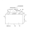
- FIG. 1 is an explanatory diagram illustrating an outline of a lithium secondary battery according to Embodiment 1.
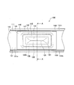
- FIG. 3 is a partial plan view showing the vicinity of a safety valve portion in the lithium secondary battery according to Embodiment 1.
- FIG. 3 is a partial plan view showing the vicinity of a safety valve portion in a state where there is no protective film in the lithium secondary battery according to Embodiment 1.
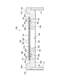
- FIG. 3 is a cross-sectional view showing the vicinity of the safety valve portion of the lithium secondary battery according to Embodiment 1, and is a cross-sectional view taken along the line AA in FIG. FIG.
- FIG. 4 is an explanatory diagram showing a state in which a safety valve portion is activated and gas pressure is applied to a valve-compatible non-adhered portion of a protective film with respect to the lithium secondary battery according to Embodiment 1.
- FIG. 4 is an explanatory diagram showing a state in which the first fixing portion of the protective film is first peeled from the battery case with respect to the lithium secondary battery according to Embodiment 1.
- FIG. 4 is an explanatory diagram showing a state in which a second fixing portion of the protective film is peeled from the battery case with respect to the lithium secondary battery according to Embodiment 1.
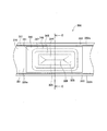
- FIG. 4 is a partial plan view showing the vicinity of a safety valve portion in a lithium secondary battery according to Embodiment 2.
- FIG. 9 is a cross-sectional view showing the vicinity of a safety valve portion in a lithium secondary battery according to Embodiment 2, and is a cross-sectional view taken along line BB in FIG.
- FIG. 6 is a partial plan view showing the vicinity of a safety valve portion in a lithium secondary battery according to Embodiment 3.
- FIG. 11 is a cross-sectional view showing the vicinity of a safety valve portion of a lithium secondary battery according to Embodiment 3, and is a cross-sectional view taken along the line CC in FIG. It is a fragmentary top view which shows the vicinity of a safety valve part among the lithium secondary batteries which concern on the modification of Embodiment 3.
- FIG. 1 schematically shows a lithium secondary battery (sealed battery) 100 according to the first embodiment.
- FIGS. 2 to 4 show the vicinity of the safety valve portion 125 in the lithium secondary battery 100. 2 shows a state where the protective film 140 is fixed, and FIG. 3 shows a state where the protective film 140 is not fixed. 4 is a cross-sectional view taken along the line AA in FIG.
- the lithium secondary battery 100 is a prismatic battery that is mounted on a hybrid car or an electric vehicle and used as a power source.
- the lithium secondary battery 100 includes a battery case 110, an electrode body (not shown) housed in the battery case 110, a positive terminal 161 and a negative terminal 163 fixed to the battery case 110, respectively (FIG. 1). reference). Further, in the lithium secondary battery 100, a protective film 140 is fixed to the battery case 110 so as to cover the safety valve portion 125 in order to protect the safety valve portion 125 provided in the battery case 110 from the outside.
- the battery case 110 is made of metal and has a rectangular parallelepiped shape.
- the battery case 110 includes a case upper wall portion 111, a case lower wall portion 112 that faces the case upper wall portion 111, and four case side wall portions 113, 114, 115, and 116 that connect them.
- the case upper wall portion 111, the case lower wall portion 112, and the case side wall portions 113, 114, 115, and 116 each have a substantially flat plate shape.
- the case upper wall part 111 has an elongated rectangular shape in plan view, and is welded to the case side wall portions 113, 114, 115, 116 at the peripheral portion.
- a positive electrode terminal 161 and a negative electrode terminal 163 are respectively fixed at predetermined positions near both ends in the longitudinal direction of the case upper wall 111 (see FIG. 1).
- the positive electrode terminal 161 is electrically connected to a positive electrode current collector of an electrode body (not shown) inside the battery, and protrudes upward from the case upper wall portion 111 and is used for electrical connection to the outside.
- the negative electrode terminal 163 is electrically connected to a negative electrode current collector of an electrode body (not shown) inside the battery, and protrudes upward from the case upper wall portion 111 and is used for electrical connection with the outside.
- a liquid injection port 121 for injecting the electrolytic solution into the battery case 110 is provided at a predetermined position on the negative electrode terminal 163 side from the center of the case upper wall portion 111.
- a case opening 123 having a rectangular shape in plan view is provided at the center of the case upper wall 111.
- a safety valve 125 having a rectangular shape in a plan view is provided below the case opening 123 (on the battery inner side) so as to close the case opening 123 (see FIG. 4).
- the safety valve portion 125 is formed integrally with the case upper wall portion 111 and forms a part of the case upper wall portion 111.
- the safety valve portion 125 is formed in a thin film shape that is thinner than the case upper wall portion 111, and a fracture portion 126 formed of a V-shaped groove is formed in a predetermined shape on the upper side.
- the safety valve unit 125 operates when the internal pressure inside the battery reaches a predetermined pressure. That is, when the internal pressure reaches a predetermined pressure, the fracture portion 126 breaks, and the internal gas is released to the outside (see FIGS. 6 and 7).
- the periphery of the breakage portion 126 and the periphery of the case opening portion 123 form a ring-shaped ring surrounding the breakage portion 126 and the case opening portion 123, and upward.
- a protruding inner annular convex portion (convex portion) 128 is formed integrally with the case upper wall portion 111 (see FIGS. 2 to 4).
- the inner annular convex portion 128 has a flat top surface 128n having a mouth shape in plan view.
- a ring-shaped lower portion formed around the inner annular convex portion 128 has a lip-shaped annular shape surrounding the inner annular convex portion 128 and is lower than the inner annular convex portion 128.
- (Lower part) 131 is formed.
- the upper surface of the annular lower portion 131 is positioned lower than the top surface 128n of the inner annular convex portion 128, and is a flat lower surface 131n having a square shape in plan view.
- a ring-shaped annular shape surrounding the lower annular portion 131 is formed around the lower annular portion 131, and a peripheral annular convex portion 133 protruding upward is provided on the upper case wall. It is formed integrally with the part 111.
- the peripheral annular protrusion 133 constitutes the peripheral portion of the case upper wall portion 111.
- the peripheral annular convex portion 133 has a top surface 133n that is higher (located above) than the lower surface 131n of the annular lower portion 131 and higher (located above) than the top surface 128n of the inner annular convex portion 128. .
- the top surface 133n forms a flat surface with a square shape in plan view.
- a protective film 140 is detachably fixed to the case upper wall portion 111 so as to cover the case opening 123 (safety valve portion 125) from the outside of the case (from above). Specifically, the protective film 140 is affixed to the case upper wall 111 by adhesion.
- the protective film 140 includes a protective film main body 141 as a base material and an adhesive layer 142 formed on the entire lower surface 141b of the protective film main body 141 that is fixed to the case upper wall portion 111. Yes.
- the protective film 140 is made of resin.
- the protective film main body 141 is formed of a synthetic resin (in this embodiment, PPS), and the adhesive layer 142 is formed of an acrylic adhesive.
- the protective film 140 includes a valve-compatible non-adhering portion 144, a first adhering portion 145, an intermediate non-adhering portion 146, and a second adhering portion 147.
- the valve-compatible non-adhering portion 144 is disposed on the case opening 123 and has a rectangular shape in plan view facing the fracture portion 126 and the safety valve portion 125, and is fixed to the case upper wall portion 111.
- the first adhering portion 145 is located outside the valve corresponding non-adhering portion 144 (on the peripheral side of the valve corresponding non-adhering portion 144), and is a portion fixed around the case opening 123 in the case upper wall portion 111. is there.
- the first fixing portion 145 has a ring-shaped annular shape surrounding the case opening 123, and the adhesive layer 142 is formed on the top surface 128 n of the inner annular convex portion 128 of the case upper wall portion 111. It is stuck.
- the second adhering portion 147 is a portion that is located outside the first adhering portion 145 via an intermediate non-adhering portion 146 described below, and is adhering to the case upper wall portion 111.
- the second fixing portion 147 has a ring-shaped annular shape surrounding the first fixing portion 145 via the intermediate non-fixing portion 146, and the lower surface of the annular lower portion 131 of the case upper wall portion 111. 131 n is fixed by an adhesive layer 142.
- the intermediate non-fixed portion 146 is a portion located between the first fixed portion 145 and the second fixed portion 147, and is a portion not fixed to the case upper wall portion 111.
- the intermediate non-fixed portion 146 has a ring-shaped annular shape surrounding the first fixed portion 145, and completely separates the first fixed portion 145 and the second fixed portion 147.
- the first fixing portion 145 is fixed to the top surface 128n of the inner annular convex portion 128, and the second fixing portion 147 is fixed to the lower surface 131n of the annular lower portion 131. Therefore, the intermediate non-fixed portion 146 is inclined with respect to the top surface 128n and the lower surface 131n, and there is a gap (space) between the intermediate non-fixed portion 146 and the case upper wall portion 111.
- CK1 is formed.
- the protective film 140 is fixed to the battery case 110 (specifically, the case upper wall portion 111) by the two fixing portions of the first fixing portion 145 and the second fixing portion 147.
- the area of the entire fixing portion can be increased. Therefore, the protective film 140 is difficult to peel off from the battery case 110 over a long period of time, and the fixing durability of the protective film 140 can be improved.
- the safety valve unit 125 operates when the internal pressure of the battery reaches a predetermined pressure (see FIG. 5). That is, the break portion 126 of the safety valve portion 125 is broken, and the gas is ejected from the safety valve portion 125. First, the gas pressure of the jetted gas is applied only to the valve-corresponding non-adhering portion 144 of the protective film 140 facing the safety valve portion 125 (breaking portion 126).
- the first fixing portion 145 of the two fixing portions precedes the second fixing portion 147. 110 (specifically, the top surface 128n of the inner annular convex portion 128 of the case upper wall portion 111) is peeled off (see FIG. 6).
- the pressure receiving area of the gas increases at a stroke.
- the pressure receiving area of the protective film 140 where the gas pressure is applied is included in the first adhering portion 145.
- the entire intermediate non-adhering portion 146 is also added, and the pressure receiving area is increased at once.
- the second fixing portion 147 is easily peeled off from the battery case 110, and peeling of the second fixing portion 147 proceeds.
- the second fixing portion 147 is also peeled off from the battery case 110 (specifically, the lower surface 131 n of the annular lower portion 131 of the case upper wall portion 111), and the second fixing portion 147.
- the inside and outside (outside) communicate with each other, and gas is released to the outside.
- peeling occurs stepwise, the ease of peeling of the protective film 140 when the safety valve unit 125 is activated can be improved. Therefore, in the lithium secondary battery 100 of the first embodiment, both the fixing durability of the protective film 140 during normal operation and the ease of peeling of the protective film 140 during operation of the safety valve can be achieved.
- the safety valve portion 125 in the normal state includes these fixing portions 145, 147. Is surely cut off from the outside of the case (see FIG. 4). For this reason, droplets of foreign matter, water, oil or the like adhere to the safety valve portion 125, particularly the fracture portion 126, thereby further improving the effect of preventing the safety valve portion 125 from being corroded. .
- the first fixed portion 145 and the second fixed portion 147 are separated via the intermediate non-fixed portion 146, stepwise peeling at the time of the above-described safety valve operation is performed. Can be performed more reliably.
- the first fixing portion 145 has an annular shape as described above, when the first fixing portion 145 peels off when the safety valve is activated, and the inside and the outside of the first fixing portion 145 communicate with each other, Since the gas reaches the entire intermediate non-fixed portion 146 located outside the first fixed portion 145, the pressure receiving area is particularly large. Thereby, since the 2nd adhering part 147 peels more reliably, the ease of peeling of the protective film 140 at the time of a safety valve action can be improved especially.
- the intermediate non-fixed portion 146 located between the first fixed portion 145 and the second fixed portion 147 is inclined (FIG. 4).
- the area of the actual intermediate non-fixed portion 146 is larger than the area of the intermediate non-fixed portion 146 when the protective film 140 fixed to the battery case 110 is viewed in plan (see FIG. 2). Yes. That is, the actual area of the intermediate non-adhered portion 146 is increased without increasing the outer size of the protective film 140 fixed to the battery case 110.
- the pressure receiving area of the protective film 140 is increased after the first fixing portion 145 is peeled off from the battery case 110, so that the second fixing portion 147 is more reliable from the battery case 110. Peel off. Therefore, the ease of peeling of the protective film 140 when the safety valve is activated can be further improved.
- the first fixing portion 145 and the second fixing portion 147 are fixed to the battery case 110 by adhesion, so that the protective film 140 is easily and reliably attached to the battery case 110. Can be fixed to. Therefore, the lithium secondary battery 100 can be made inexpensive, and the fixing durability of the protective film 140 can be sufficiently secured. Moreover, in the lithium secondary battery 100 of Embodiment 1, since the adhesive layer 142 is formed on the entire lower surface 141b of the protective film main body 141, the protective film 140 is formed as compared with the case where the adhesive layer is formed only on a part thereof. It can be made cheap. Therefore, also in this respect, the lithium secondary battery 100 can be made inexpensive. In addition, alignment when the protective film 140 is attached to the battery case 110 is also easier than in the case where the adhesive layer is formed only on a part of the protective film.
- the protective film 140 can be made inexpensive by forming the protective film 140 from a resin as compared with the case where the protective film 140 is formed from a metal foil or the like.
- the lithium secondary battery 100 can be made inexpensive.
- the protective film 140 since the protective film 140 is made of resin, the protective film 140 can be easily made flexible. Therefore, even when there is unevenness like the case upper wall portion 111 of the first embodiment, the protective film 140 140 can be easily and reliably fixed to the battery case 110. Thereby, it is possible to sufficiently secure the fixing durability of the protective film 140.
- the lithium secondary battery 200 according to the second embodiment is different from the first embodiment in that the case upper wall portion 211 has no inner annular convex portion and the case upper wall portion 211 has an annular concave groove portion 229. Different from the lithium secondary battery 100. Other than that, it is basically the same as in the first embodiment, and therefore the description of the same parts as in the first embodiment is omitted or simplified.
- the lithium secondary battery 200 includes a battery case 210, an electrode body (not shown), a positive electrode terminal 161 and a negative electrode terminal 163, a protective film 240, and the like (see FIG. 1).
- the case lower wall portion 112 and the case side wall portions 113, 114, 115, 116 are the same as the battery case 110 of the first embodiment, but the case upper wall portion 211 is in the form of the first embodiment.
- the case upper wall 111 is different.
- the case upper wall 211 is formed with a case opening 223 having a rectangular shape in plan view similar to that of the first embodiment. However, no annular convex portion exists around the case opening 223.
- the periphery of the case opening 223 is an inner annular portion 228 that forms a ring-shaped ring surrounding the case opening 223.
- the upper surface of the inner annular portion 228 is a flat annular surface 228n having a square shape in plan view.
- the inner annular portion 228 is formed around the inner annular portion 228 in a ring-shaped annular shape that surrounds the inner annular portion 228, and an annular groove portion 229 that is recessed downward from the annular surface 228n. Is formed.
- the periphery of the annular groove portion 229 is an outer annular portion 231 that forms a circular ring shape surrounding the annular groove portion 229.
- the upper surface of the outer annular portion 231 is a flat plane having a square shape in plan view, and has an annular surface 231n having the same height as the annular surface 228n of the inner annular portion 228.
- a peripheral ring-shaped convex portion 233 that forms a mouth-shaped ring surrounding the outer annular portion 231 and projects upward is formed around the outer annular portion 231. It is formed integrally with the part 211.
- the peripheral annular convex portion 233 is similar to the peripheral annular convex portion 133 of the first embodiment, has a top surface 233n, and constitutes the peripheral portion of the case upper wall portion 211.
- the protective film 240 is detachably fixed (specifically adhered) to the case upper wall portion 211 in a form that covers the case opening 223 (safety valve portion 225) from the outside of the case. Similar to the protective film 140 of the first embodiment, the protective film 240 includes a protective film main body 241 and an adhesive layer 242 formed on the entire lower surface 241b.
- the protective film 240 includes a valve-compatible non-adhering portion 244, a first adhering portion 245, an intermediate non-adhering portion 246, and a second adhering portion 247.
- the valve-corresponding non-adhering portion 244 is a portion that is disposed on the case opening 223 and has a rectangular shape in plan view facing the safety valve portion 225, and is not fixed to the case upper wall portion 211.
- the first fixing portion 245 is a portion fixed to the periphery of the fracture portion 226 and the case opening 223 in the case upper wall portion 211.
- the first fixing portion 245 has a ring-shaped annular shape surrounding the case opening 223, and is fixed to the annular surface 228 n of the inner annular portion 228 of the case upper wall portion 211 by the adhesive layer 242. ing.
- the second fixing portion 247 is a portion that is positioned outside the first fixing portion 245 and is fixed to the case upper wall portion 211.
- the second fixing portion 247 has a ring-like annular shape surrounding the first fixing portion 245 via an intermediate non-fixing portion 246 described below, and the outer annular portion 231 of the case upper wall portion 211. Is adhered to the annular surface 231n by an adhesive layer 242.
- the intermediate non-fixed portion 246 is located between the first fixed portion 245 and the second fixed portion 247 and is positioned on the annular groove portion 229 and is not fixed to the case upper wall portion 211.
- a gap (space) CK2 is formed between the intermediate non-fixed portion 246 and the case upper wall portion 211 (annular groove portion 229).
- the intermediate non-fixed portion 246 has a ring-like annular shape surrounding the first fixed portion 245 and completely separates the first fixed portion 245 and the second fixed portion 247.
- the protective film 240 is fixed to the battery case 210 (specifically, the case upper wall portion 211) by the two fixing portions of the first fixing portion 245 and the second fixing portion 247.
- the area of the entire fixing portion can be increased. Therefore, the protective film 240 is difficult to peel off from the battery case 210 over a long period of time, and the fixing durability of the protective film 240 can be improved.
- the safety valve unit 225 is activated when the internal pressure of the battery reaches a predetermined pressure. That is, the safety valve part 225 is broken at the breaking part 226, and gas is ejected through the safety valve part 225. First, the gas pressure of the jetted gas is applied only to the valve-corresponding non-adhering portion 244 facing the safety valve portion 225 (breaking portion 226) in the protective film 240.
- the first fixing portion 245 peels from the battery case 210 prior to the second fixing portion 247 of the two fixing portions (the first fixing portion 245 and the second fixing portion 247).
- the pressure receiving area of the gas increases at a stroke. That is, the injected gas reaches the entire intermediate non-adhered portion 246 located outside the first adhering portion 245, so that the pressure receiving area where the gas pressure is applied in the protective film 240 is included in the first adhering portion 245.
- the peeled portion and the entire intermediate non-fixed portion 246 are added, and the pressure receiving area is increased at once.
- FIG. 10 and 11 show the vicinity of the safety valve portion 325 in the lithium secondary battery 300 of the third embodiment.
- the lithium secondary battery 300 according to the third embodiment is free from the annular convex portion and the annular concave groove portion around the case opening 323 of the case upper wall portion 311, and the lithium secondary battery 300 according to the first embodiment and the second embodiment. Different from batteries 100 and 200.
- the point that the adhesive layer 342 of the protective film 340 is partially formed rather than the entire surface of the protective film main body 341 is different from the lithium secondary batteries 100 and 200 of the first and second embodiments.
- it is basically the same as in the first or second embodiment, so the description of the same parts as in the first or second embodiment will be omitted or simplified.
- the lithium secondary battery 300 includes a battery case 310, an electrode body (not shown), a positive electrode terminal 161, a negative electrode terminal 163, a protective film 340, and the like (see FIG. 1).
- the case lower wall portion 112 and the case side wall portions 113, 114, 115, 116 are the same as the battery case 110 of the first embodiment, but the case upper wall portion 311 has the form of the first embodiment. , 2 are different from the case upper wall portions 111, 211.
- the case upper wall portion 311 is formed with a case opening portion 323 having a rectangular shape in plan view similar to that of the first embodiment. However, there are no annular convex portions or annular concave grooves around the case opening 323.
- the periphery of the case opening 323 is an annular portion 331 that forms a ring-shaped ring surrounding the case opening 323.
- the upper surface of the annular portion 331 is a flat annular surface 331n having a square shape in plan view.
- the case upper wall portion 311 has a ring-shaped annular shape surrounding the annular portion 331 around the annular portion 331, and a peripheral annular convex portion 333 projecting upward is provided on the case upper wall portion 311. And is formed integrally.
- the peripheral annular convex portion 333 is the same as the peripheral annular convex portion 133 of the first embodiment, has a top surface 333n, and constitutes the peripheral portion of the case upper wall portion 311.
- a protective film 340 is fixed (specifically adhered) to the case upper wall portion 311 so as to cover the case opening 323 (safety valve portion 325) from the outside of the case.
- the protective film 340 includes a protective film main body 341 and an adhesive layer 342 partially formed on the lower surface 341b of the protective film main body 341 that is fixed to the case upper wall portion 311.
- the adhesive layer 342 is formed at a predetermined position on the inner side and forms an inner adhesive portion 342p that forms a ring-shaped ring shape, and an outer bonding portion 342q that forms at a predetermined position outside the ring-shaped ring shape and forms an annular shape that forms a mouth shape. Consists of.
- the portion having the inner adhesive portion 342p forms the first fixing portion 345
- the portion having the outer adhesive portion 342q forms the second fixing portion 347.
- a portion where the adhesive layer 342 does not exist in the center portion than the first fixed portion 345 becomes a valve-compatible non-adhered portion 344, and a portion where the adhesive layer 342 does not exist between the first fixed portion 345 and the second fixed portion 347. Is an intermediate non-bonding portion 346.
- the valve-corresponding non-adhering portion 344 is a portion that is disposed on the case opening 323 and has a rectangular shape in plan view facing the safety valve portion 325, and is not fixed to the case upper wall portion 311.
- the first fixing portion 345 is a portion of the case upper wall portion 311 that is fixed around the fracture portion 326 and the case opening 323.
- the first fixing portion 345 has a ring-shaped annular shape surrounding the case opening 323, and the adhesive layer 342 (specifically, on the annular surface 331 n of the annular portion 331 of the case upper wall portion 311). Are fixed by an inner adhesive portion 342p).
- the second fixing portion 347 is a portion that is located outside the first fixing portion 345 and is fixed to the case upper wall portion 311. Specifically, the second fixing portion 347 has a ring-shaped annular shape surrounding the first fixing portion 345 via the intermediate non-fixing portion 346, and the annular surface 331n of the annular portion 331 of the case upper wall portion 311. Further, it is fixed by an adhesive layer 342 (specifically, an outer adhesive portion 342q).
- the intermediate non-fixed portion 346 is a portion located between the first fixed portion 345 and the second fixed portion 347 and is not fixed to the case upper wall portion 311.
- the intermediate non-fixed portion 346 has a ring-shaped annular shape surrounding the first fixed portion 345, and completely separates the first fixed portion 345 and the second fixed portion 347.
- the protective film 340 is fixed to the battery case 310 (specifically, the case upper wall portion 311) by the two fixing portions of the first fixing portion 345 and the second fixing portion 347.
- the area of the entire fixing portion can be increased. Therefore, the protective film 340 is difficult to peel off from the battery case 310 over a long period of time, and the fixing durability of the protective film 340 can be improved.
- the safety valve unit 325 when the internal pressure of the battery reaches a predetermined pressure, the safety valve unit 325 is activated. That is, the safety valve portion 325 is broken at the breaking portion 326, and gas is ejected through the safety valve portion 325. First, the gas pressure of the jetted gas is applied only to the valve-corresponding non-adhering portion 344 of the protective film 340 facing the safety valve portion 325 (breaking portion 326).
- the first fixing portion 345 is peeled off from the battery case 310 prior to the second fixing portion 347 of the two fixing portions (the first fixing portion 345 and the second fixing portion 347). To do.
- the pressure receiving area of the gas increases at a stroke. That is, since the injected gas reaches the entire intermediate non-adhered portion 346 located outside the first adhering portion 345, the pressure receiving area of the protective film 340 where the gas pressure is applied is included in the first adhering portion 345. The peeled portion and the entire intermediate non-adhered portion 346 are added, and the pressure receiving area is increased at once.
- the second fixing portion 347 is also peeled off from the battery case 310, and the inside and the outside (outside) of the second fixing portion 347 communicate with each other, and the gas is released to the outside.
- peeling occurs stepwise, it is possible to improve the ease of peeling of the protective film 340 when the safety valve unit 325 is activated. Therefore, also in the lithium secondary battery 300 of the third embodiment, it is possible to achieve both the fixing durability of the protective film 340 during normal operation and the ease of peeling of the protective film 340 during operation of the safety valve.
- the same parts as those in the first or second embodiment have the same effects as those in the first or second embodiment.
- the present invention has been described with reference to the embodiments.
- the present invention is not limited to the above-described first to third embodiments, and it is needless to say that the present invention can be appropriately modified and applied without departing from the gist thereof.
- the safety valve portions 125, 225, and 325 are integrally formed with the case upper wall portions 111, 211, and 311 of the battery cases 110, 210, and 310.
- the present invention can also be applied to a safety valve part that is formed separately from the battery case and then joined to the battery case.
- the safety valve portions 125, 225, and 325 are exemplified as those provided below the case openings 123, 223, and 323 (inside the case), but the safety valve portions 125, 225, and 325 are exemplified. 325 can also be provided above the case openings 123, 223, and 323 (on the outside of the case).
- the first fixing portions 145, 245, and 345 of the protective films 140, 240, and 340 are exemplified as an annular shape that surrounds the case openings 123, 223, and 323. It can be an intermittent island that exists intermittently around the case openings 123, 223, and 323.
- FIG. 12 shows a lithium secondary battery 400 according to a modification of the third embodiment, and the first fixing portion 445 of the protective film 440 is intermittently formed around the fracture portion 326 and the case opening 325. It is good also as the intermittent island shape which exists in a shape.
- the first fixed portions 145, 245, 345 and the second fixed portions 147, 247, 347 are completely separated by the intermediate non-fixed portions 146, 246, 346.
- the first fixing portions 145, 245, 345 and the second fixing portions 147, 247, 347 may be partially connected.
- Lithium secondary battery 110, 210, 310 Battery case 111, 211, 311 Case upper wall part 125, 225, 325 Safety valve part 126, 226, 326 Breaking part 128 Inner annular convex part (convex part) 128n Top surface 131 Annular low part (low part) 131 n Lower surface 140, 240, 340, 440 Protective film 141, 241, 341 Protective film body 142, 242, 342 Adhesive layer 144, 244, 344 Valve corresponding non-adhering part 145, 245, 345, 445 First fixing part 146 246, 346 Intermediate non-fixed portion 147, 247, 347 Second fixed portion
Landscapes
- Chemical & Material Sciences (AREA)
- Chemical Kinetics & Catalysis (AREA)
- Electrochemistry (AREA)
- General Chemical & Material Sciences (AREA)
- Engineering & Computer Science (AREA)
- Manufacturing & Machinery (AREA)
- Gas Exhaust Devices For Batteries (AREA)
- Electric Double-Layer Capacitors Or The Like (AREA)
Abstract
Description
このように保護膜を電池ケースにベタ状に固着した(安全弁に面する部分を避けて安全弁の周囲にベタ状に固着した)従来の電池においては、通常時における保護膜の固着耐久性と、安全弁作動時における保護膜の剥離容易性とを両立させることが困難であった。 On the other hand, if the area of the solid adhering portion of the protective film is reduced, the protective film is surely peeled off from the battery case when the safety valve is activated, and the gas can be reliably discharged to the outside of the protective film. However, in this case, the protective film is easily peeled off from the battery case even during normal times, and a problem arises in the fixing durability of the protective film.
In this way, in the conventional battery in which the protective film is fixed in a solid shape on the battery case (a solid surface is fixed around the safety valve while avoiding the portion facing the safety valve), It was difficult to achieve both the easy peeling of the protective film when the safety valve was activated.
一方、この電池では、内圧上昇により安全弁部が開弁して噴出したガスにより、弁対応非固着部にガス圧が掛かった場合に(安全弁作動時に)、第2固着部に先立って、第1固着部の少なくとも一部が電池ケースから剥離する。すると、保護膜のうちガス圧が掛かる受圧面積に、第1固着部のうち剥離した部分も含まれることとなって、受圧面積が多くなり、第2固着部により大きな力が掛かるため、この第2固着部が電池ケースから剥離しやすくなり、第2固着部の剥離が進行する。そして、第2固着部の内側と外側(外部)が連通して、ガスが外部に放出される。このように、安全弁作動時の保護膜の剥離容易性を向上させることができる。
従って、この電池では、通常時における保護膜の固着耐久性と、安全弁作動時における保護膜の剥離容易性を両立させることができる。 In this battery, since at least the first fixing portion and the second fixing portion of the protective film are fixed to the battery case, the area of the entire fixing portion can be increased. Therefore, it is difficult for the protective film to peel from the battery case over a long period of time, and the fixing durability of the protective film can be improved.
On the other hand, in this battery, when the gas pressure is applied to the non-adhered part corresponding to the valve due to the gas ejected by opening the safety valve part due to the increase in internal pressure (when the safety valve is activated), the first At least a part of the fixing portion is peeled off from the battery case. Then, the pressure receiving area to which the gas pressure is applied in the protective film includes the peeled portion of the first fixing portion, so that the pressure receiving area increases and a large force is applied to the second fixing portion. 2 It becomes easy to peel a fixed part from a battery case, and peeling of a 2nd fixed part advances. And the inner side and the outer side (outside) of a 2nd adhering part are connected, and gas is discharge | released outside. Thus, the ease of peeling of the protective film when the safety valve is activated can be improved.
Therefore, in this battery, both the fixing durability of the protective film during normal operation and the ease of peeling of the protective film during operation of the safety valve can be achieved.
「電池ケース」の形状としては、例えば、円柱状や直方体状などが挙げられる。
「保護膜」の形状(平面視形状)としては、例えば、矩形状、円状、長円状、楕円状、多角形状などが挙げられる。
「第1固着部」の形態としては、例えば、弁対応非固着部を取り囲む環状や、弁対応非固着部の周囲に断続的に存在する断続的形状とすることができる。また、「第1固着部」と「第2固着部」とは、中間非固着部を介して完全に分離された形態としてもよいし、「第1固着部」と「第2固着部」が一部で繋がった形態としてもよい。 Examples of the form of the “safety valve portion” include those formed integrally with the battery case and those formed separately from the battery case and then joined to the battery case.
Examples of the shape of the “battery case” include a columnar shape and a rectangular parallelepiped shape.
Examples of the shape (planar shape) of the “protective film” include a rectangular shape, a circular shape, an oval shape, an elliptical shape, and a polygonal shape.
As the form of the “first fixing portion”, for example, an annular shape surrounding the valve-corresponding non-adhering portion or an intermittent shape intermittently existing around the valve-corresponding non-adhering portion can be used. In addition, the “first fixing portion” and the “second fixing portion” may be completely separated via an intermediate non-fixing portion, or the “first fixing portion” and the “second fixing portion” may be provided. It is good also as the form connected in part.
なお、接着の具体的な形態としては、保護膜に接着層を設け、この保護膜を電池ケースに貼り付けた形態や、電池ケースの方に接着層を設けておき、この電池ケースに保護膜を貼り付けた形態などが挙げられる。 By fixing the first fixing portion and the second fixing portion to the battery case by bonding, the protective film can be fixed to the battery case easily and reliably. Therefore, the battery can be made inexpensive and the protective film can be sufficiently secured.
As a specific form of adhesion, an adhesive layer is provided on the protective film, and the protective film is attached to the battery case, or an adhesive layer is provided on the battery case, and the protective film is provided on the battery case. The form which stuck is mentioned.
以下、第1の実施の形態を、図面を参照しつつ説明する。図1に、本実施形態1に係るリチウム二次電池(密閉型電池)100の概略を示す。また、図2~図4に、このリチウム二次電池100のうち、安全弁部125の近傍を示す。なお、図2は、保護膜140を固着した状態を示し、図3は、保護膜140を固着していない状態を示している。また、図4は、図2におけるA-A断面図である。このリチウム二次電池100は、ハイブリットカーや電気自動車に搭載されて、その動力源として利用される角型電池である。 (Embodiment 1)
The first embodiment will be described below with reference to the drawings. FIG. 1 schematically shows a lithium secondary battery (sealed battery) 100 according to the first embodiment. FIGS. 2 to 4 show the vicinity of the
また、ケース上壁部111の中央よりも負極端子163側の所定位置には、電解液を電池ケース110内に注入する為の注液口121が設けられている。 Among these, the case
In addition, a
また、ケース上壁部111のうち、内側環状凸部128の周囲には、内側環状凸部128を取り囲む口字状の環状をなすと共に、内側環状凸部128よりも低位とされた環状低位部(低位部)131が形成されている。この環状低位部131の上面は、内側環状凸部128の頂面128nよりも低位に位置し、平面視口字状をなす平坦な低位面131nとされている。 Of the case
Further, in the case
この保護膜140は、基材である保護膜本体141と、この保護膜本体141のうち、ケース上壁部111に固着させる側の下面141bの全体に形成された接着層142とから構成されている。この保護膜140は、樹脂により形成されている。具体的には、保護膜本体141は、合成樹脂(本実施形態ではPPS)により形成されており、接着層142は、アクリル系接着剤により形成されている。 A
The
このうち弁対応非固着部144は、ケース開口部123上に配置され、破断部126、更には安全弁部125に面する平面視矩形状をなす部分であり、ケース上壁部111には固着していない。
第1固着部145は、弁対応非固着部144の外側(弁対応非固着部144よりも周縁側)に位置し、ケース上壁部111のうち、ケース開口部123の周囲に固着した部分である。具体的には、この第1固着部145は、ケース開口部123を取り囲む口字状の環状をなし、ケース上壁部111のうちの内側環状凸部128の頂面128nに、接着層142により固着している。 The
Of these, the valve-compatible
The first adhering
第1固着部145の少なくとも一部が剥離して、第1固着部145の内側と外側が連通すると、ガスの受圧面積が一挙に大きくなる。即ち、噴射したガスが、第1固着部145の外側に位置する中間非固着部146の全体にも達するため、保護膜140のうちガス圧が掛かる受圧面積には、第1固着部145のうち剥離した部分が加わる他、中間非固着部146の全体も加わり、受圧面積が一挙に大きくなる。 Then, due to the force generated thereby, at least a part of the
When at least a part of the
よって、本実施形態1のリチウム二次電池100では、通常時における保護膜140の固着耐久性と、安全弁作動時における保護膜140の剥離容易性を両立させることができる。 Then, since a large force is applied to the
Therefore, in the lithium
また、実施形態1のリチウム二次電池100では、保護膜本体141の下面141b全体に接着層142を形成しているので、一部分にのみ接着層を形成する場合に比して、保護膜140を安価にすることができる。従って、この点でもリチウム二次電池100を安価にすることができる。また、保護膜の一部分にのみ接着層を形成する場合に比して、保護膜140を電池ケース110に貼り付けるときの位置合わせも容易となる。 Further, in the lithium
Moreover, in the lithium
次いで、第2の実施の形態について説明する。図8及び図9に、本実施形態2のリチウム二次電池200のうち、安全弁部225の近傍を示す。本実施形態2のリチウム二次電池200は、ケース上壁部211に内側環状凸部が無い点と、ケース上壁部211に環状凹溝部229が設けられている点が、上記実施形態1のリチウム二次電池100と異なる。それ以外は、基本的に上記実施形態1と同様であるので、上記実施形態1と同様な部分の説明は、省略または簡略化する。 (Embodiment 2)
Next, a second embodiment will be described. 8 and 9 show the vicinity of the
電池ケース210のうち、ケース下壁部112及びケース側壁部113,114,115,116は、上記実施形態1の電池ケース110の同様であるが、ケース上壁部211の形態が上記実施形態1のケース上壁部111と異なる。 Similar to the first embodiment, the lithium
Of the
また、ケース上壁部211のうち、環状凹溝部229の周囲は、環状凹溝部229を取り囲む口字状の環状をなす外側環状部231とされている。この外側環状部231の上面は、平面視口字状をなす平坦な平面で、内側環状部228の環状面228nと同じ高さの環状面231nを有する。 Of the case
Further, in the case
この保護膜240は、弁対応非固着部244と、第1固着部245と、中間非固着部246と、第2固着部247とからなる。 The
The
第1固着部245は、ケース上壁部211のうち、破断部226及びケース開口部223の周囲に固着した部分である。具体的には、第1固着部245は、ケース開口部223を取り囲む口字状の環状をなし、ケース上壁部211のうちの内側環状部228の環状面228nに、接着層242により固着している。 Among these, the valve-corresponding
The
中間非固着部246は、第1固着部245と第2固着部247との間に位置すると共に、環状凹溝部229上に位置する部分であり、ケース上壁部211には固着していない。中間非固着部246とケース上壁部211(環状凹溝部229)との間には、隙間(空間)CK2が形成されている。この中間非固着部246は、第1固着部245を取り囲む口字状の環状をなし、第1固着部245と第2固着部247を完全に分離している。 The
The intermediate
よって、本実施形態2のリチウム二次電池200でも、通常時における保護膜240の固着耐久性と、安全弁作動時における保護膜240の剥離容易性を両立させることができる。その他、上記実施形態1と同様な部分は、上記実施形態1と同様な作用効果を奏する。 Then, since the big force by this is applied to the 2nd adhering
Therefore, also in the lithium
次いで、第3の実施の形態について説明する。図10及び図11に、本実施形態3のリチウム二次電池300のうち、安全弁部325の近傍を示す。本実施形態3のリチウム二次電池300は、ケース上壁部311のケース開口部323の周囲に環状凸部や環状凹溝部が無い点が、上記実施形態1や上記実施形態2のリチウム二次電池100,200と異なる。また、保護膜340の接着層342が保護膜本体341の全面にではなく部分的に形成されている点が、上記実施形態1,2のリチウム二次電池100,200と異なる。それ以外は、基本的に上記実施形態1または2と同様であるので、上記実施形態1または2と同様な部分の説明は、省略または簡略化する。 (Embodiment 3)
Next, a third embodiment will be described. 10 and 11 show the vicinity of the
電池ケース310のうち、ケース下壁部112及びケース側壁部113,114,115,116は、上記実施形態1の電池ケース110の同様であるが、ケース上壁部311の形態が上記実施形態1,2のケース上壁部111,211と異なる。 Similar to the first embodiment, the lithium
Of the
第1固着部345は、ケース上壁部311のうち、破断部326及びケース開口部323の周囲に固着した部分である。具体的には、第1固着部345は、ケース開口部323を取り囲む口字状の環状をなし、ケース上壁部311のうちの環状部331の環状面331nに、接着層342(具体的には内側接着部342p)により固着している。 Among these, the valve-corresponding
The
中間非固着部346は、第1固着部345と第2固着部347との間に位置する部分であり、ケース上壁部311には固着していない。この中間非固着部346は、第1固着部345を取り囲む口字状の環状をなし、第1固着部345と第2固着部347を完全に分離している。 The
The intermediate
よって、本実施形態3のリチウム二次電池300でも、通常時における保護膜340の固着耐久性と、安全弁作動時における保護膜340の剥離容易性を両立させることができる。その他、上記実施形態1または2と同様な部分は、上記実施形態1または2と同様な作用効果を奏する。 Then, since the big force by this is applied to the 2nd adhering
Therefore, also in the lithium
例えば、上記実施形態1~3では、安全弁部125,225,325の形態として、電池ケース110,210,310のケース上壁部111,211,311と一体的に形成されたものを示したが、安全弁部を電池ケースと別体で形成した後に電池ケースに接合したものについても、本発明を適用できる。
また、上記実施形態1~3では、安全弁部125,225,325として、ケース開口部123,223,323の下方側(ケース内部側)に設けたものを例示したが、安全弁部125,225,325は、ケース開口部123,223,323の上方側(ケース外部側)に設けることもできる。 In the above, the present invention has been described with reference to the embodiments. However, the present invention is not limited to the above-described first to third embodiments, and it is needless to say that the present invention can be appropriately modified and applied without departing from the gist thereof. Yes.
For example, in the first to third embodiments, the
In the first to third embodiments, the
例えば図12に、実施形態3の変形例に係るリチウム二次電池400を示すように、保護膜440の第1固着部445を、破断部326及びケース開口部325の周囲に、断続的に島状に存在する断続的島状としてもよい。 In the first to third embodiments, the first fixing
For example, FIG. 12 shows a lithium
110,210,310 電池ケース
111,211,311 ケース上壁部
125,225,325 安全弁部
126,226,326 破断部
128 内側環状凸部(凸部)
128n 頂面
131 環状低位部(低位部)
131n 低位面
140,240,340,440 保護膜
141,241,341 保護膜本体
142,242,342 接着層
144,244,344 弁対応非固着部
145,245,345,445 第1固着部
146,246,346 中間非固着部
147,247,347 第2固着部 100, 200, 300, 400 Lithium secondary battery (sealed battery)
110, 210, 310
131
Claims (8)
- 破断部を含み、この破断部の破断により開弁する非復元型の安全弁部を有する電池ケースと、
前記安全弁部を外部から覆って前記電池ケースに固着し、前記安全弁部を封止する保護膜と、を備える
電池であって、
前記保護膜は、
前記安全弁部の前記破断部に面すると共に、前記電池ケースに固着していない弁対応非固着部と、
前記弁対応非固着部の外側に位置し、前記電池ケースに固着する第1固着部と、
前記第1固着部の外側に、前記電池ケースに固着していない中間非固着部を介して位置し、環状をなして前記電池ケースに固着する第2固着部と、を少なくとも有する
電池。 A battery case having a non-restorable type safety valve portion including a fracture portion and opened by the fracture of the fracture portion;
A battery comprising: a protective film that covers the safety valve portion from outside and is fixed to the battery case, and seals the safety valve portion;
The protective film is
A valve-compatible non-adhering portion that faces the fracture portion of the safety valve portion and is not fixed to the battery case,
A first fixing portion that is located outside the valve-compatible non-fixing portion and is fixed to the battery case;
A battery having at least a second fixing portion that is positioned outside the first fixing portion via an intermediate non-fixing portion that is not fixed to the battery case and is fixed to the battery case in an annular shape. - 請求項1に記載の電池であって、
前記第1固着部及び前記第2固着部は、
内圧上昇により前記安全弁部が開弁して噴出したガスにより、前記弁対応非固着部にガス圧が掛かった場合に、
前記第2固着部に先立って、前記第1固着部の少なくとも一部が前記電池ケースから剥離し、
前記保護膜のうち前記ガス圧が掛かる受圧面積を大きくして、前記第2固着部の剥離を促進させ、
前記第2固着部の少なくとも一部が前記電池ケースから剥離して、前記ガスを外部に放出する形態とされてなる
電池。 The battery according to claim 1,
The first fixing part and the second fixing part are:
When the gas pressure is applied to the non-adhered portion corresponding to the valve by the gas that is blown out by opening the safety valve portion due to an increase in internal pressure,
Prior to the second fixing part, at least a part of the first fixing part is peeled off from the battery case,
Increase the pressure receiving area to which the gas pressure is applied among the protective film, and promote the peeling of the second fixing part,
A battery in which at least a part of the second fixing portion is peeled off from the battery case and the gas is released to the outside. - 請求項1または請求項2に記載の電池であって、
前記第1固着部は、前記弁対応非固着部の周囲を取り囲む環状をなす
電池。 The battery according to claim 1 or 2,
The first adhering portion is an annular battery surrounding the periphery of the valve non-adhering portion. - 請求項1または請求項2に記載の電池であって、
前記第1固着部と前記第2固着部は、前記中間非固着部を介して分離してなる
電池。 The battery according to claim 1 or 2,
The battery in which the first fixing portion and the second fixing portion are separated through the intermediate non-fixing portion. - 請求項1または請求項2に記載の電池であって、
前記電池ケースは、
前記破断部の周囲に位置し、外部に向かって突出する、頂面を含む凸部と、
前記凸部の周囲に位置し、前記頂面よりも低位とされた低位面を含む低位部と、を有し、
前記第1固着部は、前記凸部の前記頂面に固着してなり、
前記第2固着部は、前記低位部の前記低位面に固着してなる
電池。 The battery according to claim 1 or 2,
The battery case is
A convex portion including the top surface, which is located around the rupture portion and protrudes toward the outside,
A lower portion including a lower surface located around the convex portion and lower than the top surface;
The first fixing portion is fixed to the top surface of the convex portion,
The second adhering portion is a battery formed by adhering to the lower surface of the lower portion. - 請求項1または請求項2に記載の電池であって、
前記第1固着部及び前記第2固着部は、それぞれ接着により前記電池ケースに固着してなる
電池。 The battery according to claim 1 or 2,
The first fixing part and the second fixing part are each fixed to the battery case by bonding. - 請求項6に記載の電池であって、
前記保護膜は、
保護膜本体と、この保護膜本体のうち、前記電池ケースに固着される側の面全体に形成された接着層とを有する
電池。 The battery according to claim 6,
The protective film is
A battery comprising a protective film body and an adhesive layer formed on the entire surface of the protective film body on the side fixed to the battery case. - 請求項1または請求項2に記載の電池であって、
前記保護膜は、樹脂により形成されてなる
電池。 The battery according to claim 1 or 2,
The protective film is a battery formed of resin.
Priority Applications (5)
| Application Number | Priority Date | Filing Date | Title |
|---|---|---|---|
| KR1020107011783A KR101059654B1 (en) | 2008-08-20 | 2009-07-10 | battery |
| EP09808147.4A EP2328207B1 (en) | 2008-08-20 | 2009-07-10 | Battery |
| US12/739,229 US8354181B2 (en) | 2008-08-20 | 2009-07-10 | Battery |
| BRPI0906226-2A BRPI0906226B1 (en) | 2008-08-20 | 2009-07-10 | DRUMS |
| CN200980101599.5A CN101911337B (en) | 2008-08-20 | 2009-07-10 | Battery |
Applications Claiming Priority (2)
| Application Number | Priority Date | Filing Date | Title |
|---|---|---|---|
| JP2008-211872 | 2008-08-20 | ||
| JP2008211872A JP4386139B1 (en) | 2008-08-20 | 2008-08-20 | battery |
Publications (1)
| Publication Number | Publication Date |
|---|---|
| WO2010021211A1 true WO2010021211A1 (en) | 2010-02-25 |
Family
ID=41549804
Family Applications (1)
| Application Number | Title | Priority Date | Filing Date |
|---|---|---|---|
| PCT/JP2009/062571 WO2010021211A1 (en) | 2008-08-20 | 2009-07-10 | Battery |
Country Status (8)
| Country | Link |
|---|---|
| US (1) | US8354181B2 (en) |
| EP (1) | EP2328207B1 (en) |
| JP (1) | JP4386139B1 (en) |
| KR (1) | KR101059654B1 (en) |
| CN (1) | CN101911337B (en) |
| BR (1) | BRPI0906226B1 (en) |
| RU (1) | RU2462795C2 (en) |
| WO (1) | WO2010021211A1 (en) |
Cited By (3)
| Publication number | Priority date | Publication date | Assignee | Title |
|---|---|---|---|---|
| CN101901886A (en) * | 2010-07-15 | 2010-12-01 | 东莞新能源电子科技有限公司 | Power battery explosion protection device |
| EP2388846A1 (en) * | 2010-05-20 | 2011-11-23 | SB LiMotive Co., Ltd. | Secondary battery |
| JP2012178333A (en) * | 2011-01-31 | 2012-09-13 | Gs Yuasa Corp | Power storage element |
Families Citing this family (36)
| Publication number | Priority date | Publication date | Assignee | Title |
|---|---|---|---|---|
| JP5407683B2 (en) * | 2009-09-10 | 2014-02-05 | トヨタ自動車株式会社 | Battery and battery manufacturing method |
| US8658296B2 (en) * | 2010-02-25 | 2014-02-25 | Samsung Sdi Co., Ltd. | Rechargeable battery |
| DE102010013027A1 (en) * | 2010-03-26 | 2011-09-29 | Daimler Ag | Single cell for a battery |
| US9118061B2 (en) | 2010-08-13 | 2015-08-25 | Samsung Sdi Co., Ltd. | Secondary battery |
| KR101191660B1 (en) * | 2010-11-08 | 2012-10-17 | 에스비리모티브 주식회사 | Battery module |
| DE102010055401A1 (en) * | 2010-12-21 | 2012-06-21 | Li-Tec Battery Gmbh | Foil for the protection of electrochemical energy storage |
| JP5601253B2 (en) * | 2011-03-15 | 2014-10-08 | 株式会社デンソー | Battery internal pressure state detection device |
| JP5803553B2 (en) * | 2011-10-14 | 2015-11-04 | 日産自動車株式会社 | Sealed battery exhaust plug |
| CN202308124U (en) * | 2011-10-28 | 2012-07-04 | 比亚迪股份有限公司 | Battery explosion-proof device and battery pack thereof |
| US10290841B2 (en) * | 2012-01-31 | 2019-05-14 | Johnson Controls Technology Company | Cover for battery cell |
| JP6252877B2 (en) * | 2012-02-14 | 2017-12-27 | 株式会社Gsユアサ | Electricity storage element |
| JP5966922B2 (en) * | 2012-02-14 | 2016-08-10 | 株式会社Gsユアサ | Electricity storage element |
| JP5542192B2 (en) * | 2012-12-11 | 2014-07-09 | 日新製鋼株式会社 | Battery case lid |
| JP5910624B2 (en) * | 2013-12-26 | 2016-04-27 | 株式会社豊田自動織機 | Battery pack |
| DE102014202348A1 (en) * | 2014-02-10 | 2015-08-13 | Robert Bosch Gmbh | Apparatus and method for increasing safety in the use of battery systems |
| JP2015192020A (en) * | 2014-03-28 | 2015-11-02 | 新神戸電機株式会社 | lithium ion capacitor |
| KR102234702B1 (en) * | 2014-09-16 | 2021-04-01 | 삼성에스디아이 주식회사 | Case assembly, Prismatic secondary battery, and the fabrication method thereof |
| JP6493548B2 (en) * | 2015-10-05 | 2019-04-03 | 日産自動車株式会社 | Battery pack pressure release mechanism |
| CN107316956B (en) * | 2016-04-26 | 2023-04-18 | 宁德时代新能源科技股份有限公司 | Explosion-proof assembly and secondary battery top cap |
| CN106025114B (en) * | 2016-06-07 | 2018-10-09 | 宁德时代新能源科技股份有限公司 | Power battery top cap and power battery |
| KR102629177B1 (en) * | 2016-07-12 | 2024-01-26 | 삼성에스디아이 주식회사 | Secondary Battery |
| JP2018018614A (en) * | 2016-07-26 | 2018-02-01 | トヨタ自動車株式会社 | Battery pack |
| EP3601858A1 (en) | 2017-03-30 | 2020-02-05 | Donaldson Company, Inc. | Vent with relief valve |
| DE102018207733A1 (en) | 2018-05-17 | 2019-11-21 | Audi Ag | Battery cell for a vehicle battery and vehicle battery and motor vehicle |
| DE102018125110A1 (en) * | 2018-10-11 | 2020-04-16 | Dr. Ing. H.C. F. Porsche Aktiengesellschaft | Housing for a battery, in particular for a motor vehicle traction battery |
| CN209658282U (en) * | 2019-05-21 | 2019-11-19 | 宁德新能源科技有限公司 | Shell, explosion-proof valve and the battery modules containing the explosion-proof valve or the shell |
| CN210668431U (en) * | 2019-10-10 | 2020-06-02 | 宁德新能源科技有限公司 | Shell, battery and electronic device |
| DE102020109148A1 (en) * | 2020-04-02 | 2021-10-07 | Bayerische Motoren Werke Aktiengesellschaft | Battery housing with protective cap, battery and motor vehicle |
| DE102020112565A1 (en) | 2020-05-08 | 2021-11-11 | Hugo Benzing Gmbh & Co. Kg | Pressure relief valve |
| CN117497950A (en) * | 2020-07-10 | 2024-02-02 | 宁德时代新能源科技股份有限公司 | Battery box, battery cell, battery, and method and device for preparing battery box |
| KR20220164047A (en) * | 2020-11-25 | 2022-12-12 | 컨템포러리 엠퍼렉스 테크놀로지 씨오., 리미티드 | Battery cell, method and system for manufacturing battery cell, battery and electric device |
| JP7418597B2 (en) * | 2021-04-16 | 2024-01-19 | 寧徳時代新能源科技股▲分▼有限公司 | Battery cells, batteries, power consumption equipment, manufacturing methods and devices for battery cells |
| CN116438702A (en) * | 2021-08-31 | 2023-07-14 | 宁德时代新能源科技股份有限公司 | Pressure relief device, battery monomer, battery and electric equipment |
| US20230198088A1 (en) * | 2021-12-17 | 2023-06-22 | GM Global Technology Operations LLC | Battery module cover with thermal runaway mitigation |
| EP4325645A1 (en) | 2022-08-19 | 2024-02-21 | MANN+HUMMEL GmbH | Degassing unit with segmented membrane |
| CN218385448U (en) * | 2022-10-25 | 2023-01-24 | 宁德时代新能源科技股份有限公司 | Shell assembly, battery monomer, battery and consumer |
Citations (6)
| Publication number | Priority date | Publication date | Assignee | Title |
|---|---|---|---|---|
| JPH1149217A (en) * | 1997-07-28 | 1999-02-23 | Oputonikusu Seimitsu:Kk | Battery having safety-valve and safety valve used for the same |
| WO2000072388A1 (en) | 1999-05-24 | 2000-11-30 | Toyo Kohan Co.,Ltd. | Method for forming protective coating for cell safety valve device, cell safety valve device covered with protective coating, cell sealing plate comprising the same, and closed cell comprising the same |
| JP2003346762A (en) | 2002-05-24 | 2003-12-05 | Japan Storage Battery Co Ltd | Sealed battery having safety valve |
| JP2005142115A (en) | 2003-11-10 | 2005-06-02 | Nec Tokin Corp | Secondary battery |
| JP2005317390A (en) * | 2004-04-28 | 2005-11-10 | Sanyo Electric Co Ltd | Lid plate and battery |
| JP2007220508A (en) * | 2006-02-17 | 2007-08-30 | Gs Yuasa Corporation:Kk | Battery equipped with safety valve |
Family Cites Families (5)
| Publication number | Priority date | Publication date | Assignee | Title |
|---|---|---|---|---|
| DE2324254A1 (en) * | 1973-05-14 | 1974-11-28 | Varta Batterie | GALVANIC PRIMARY CELL |
| JPH10228891A (en) * | 1997-02-13 | 1998-08-25 | Shin Kobe Electric Mach Co Ltd | Sealed lead-acid battery |
| JP4100762B2 (en) | 1998-03-31 | 2008-06-11 | 三洋電機株式会社 | Lithium ion battery |
| DE60038789D1 (en) * | 1999-11-24 | 2008-06-19 | Matsushita Electric Ind Co Ltd | BATTERY |
| JP4554621B2 (en) * | 2004-01-30 | 2010-09-29 | エルジー・ケム・リミテッド | Battery with special package structure |
-
2008
- 2008-08-20 JP JP2008211872A patent/JP4386139B1/en active Active
-
2009
- 2009-07-10 KR KR1020107011783A patent/KR101059654B1/en active IP Right Grant
- 2009-07-10 RU RU2010126524/07A patent/RU2462795C2/en active
- 2009-07-10 EP EP09808147.4A patent/EP2328207B1/en active Active
- 2009-07-10 WO PCT/JP2009/062571 patent/WO2010021211A1/en active Application Filing
- 2009-07-10 US US12/739,229 patent/US8354181B2/en active Active
- 2009-07-10 BR BRPI0906226-2A patent/BRPI0906226B1/en not_active IP Right Cessation
- 2009-07-10 CN CN200980101599.5A patent/CN101911337B/en active Active
Patent Citations (6)
| Publication number | Priority date | Publication date | Assignee | Title |
|---|---|---|---|---|
| JPH1149217A (en) * | 1997-07-28 | 1999-02-23 | Oputonikusu Seimitsu:Kk | Battery having safety-valve and safety valve used for the same |
| WO2000072388A1 (en) | 1999-05-24 | 2000-11-30 | Toyo Kohan Co.,Ltd. | Method for forming protective coating for cell safety valve device, cell safety valve device covered with protective coating, cell sealing plate comprising the same, and closed cell comprising the same |
| JP2003346762A (en) | 2002-05-24 | 2003-12-05 | Japan Storage Battery Co Ltd | Sealed battery having safety valve |
| JP2005142115A (en) | 2003-11-10 | 2005-06-02 | Nec Tokin Corp | Secondary battery |
| JP2005317390A (en) * | 2004-04-28 | 2005-11-10 | Sanyo Electric Co Ltd | Lid plate and battery |
| JP2007220508A (en) * | 2006-02-17 | 2007-08-30 | Gs Yuasa Corporation:Kk | Battery equipped with safety valve |
Non-Patent Citations (1)
| Title |
|---|
| See also references of EP2328207A4 |
Cited By (5)
| Publication number | Priority date | Publication date | Assignee | Title |
|---|---|---|---|---|
| EP2388846A1 (en) * | 2010-05-20 | 2011-11-23 | SB LiMotive Co., Ltd. | Secondary battery |
| US20110287286A1 (en) * | 2010-05-20 | 2011-11-24 | Byung-Kyu Ahn | Secondary battery |
| US9065113B2 (en) | 2010-05-20 | 2015-06-23 | Samsung Sdi Co., Ltd. | Secondary battery with film covering safety vent |
| CN101901886A (en) * | 2010-07-15 | 2010-12-01 | 东莞新能源电子科技有限公司 | Power battery explosion protection device |
| JP2012178333A (en) * | 2011-01-31 | 2012-09-13 | Gs Yuasa Corp | Power storage element |
Also Published As
| Publication number | Publication date |
|---|---|
| EP2328207B1 (en) | 2015-09-09 |
| BRPI0906226B1 (en) | 2019-07-02 |
| JP4386139B1 (en) | 2009-12-16 |
| US8354181B2 (en) | 2013-01-15 |
| CN101911337B (en) | 2014-03-12 |
| KR101059654B1 (en) | 2011-08-25 |
| US20100233520A1 (en) | 2010-09-16 |
| EP2328207A1 (en) | 2011-06-01 |
| EP2328207A4 (en) | 2012-09-05 |
| BRPI0906226A2 (en) | 2015-07-07 |
| RU2462795C2 (en) | 2012-09-27 |
| CN101911337A (en) | 2010-12-08 |
| JP2010049883A (en) | 2010-03-04 |
| KR20100070385A (en) | 2010-06-25 |
Similar Documents
| Publication | Publication Date | Title |
|---|---|---|
| WO2010021211A1 (en) | Battery | |
| KR101137366B1 (en) | Secondary battery | |
| JP5966922B2 (en) | Electricity storage element | |
| JP4686399B2 (en) | Secondary battery | |
| JP5083326B2 (en) | Batteries, vehicles and devices equipped with the batteries | |
| KR101525345B1 (en) | Hermetically sealed battery | |
| JP5407683B2 (en) | Battery and battery manufacturing method | |
| KR101136320B1 (en) | Battery, vehicle, and equipment using battery | |
| JP2013187530A (en) | Explosion-proof valve for hermetic type electrochemical device | |
| JP2020119874A (en) | Secondary battery and manufacturing method thereof | |
| JP2007329076A (en) | Manufacturing method of battery and battery | |
| WO2011118359A1 (en) | Hermetic battery | |
| JP5818004B2 (en) | Sealing plate for sealed electrochemical devices | |
| JP5125249B2 (en) | Plug body with virgin function | |
| JP2005235696A (en) | Manufacturing method for battery | |
| JP6252877B2 (en) | Electricity storage element | |
| CN217589150U (en) | Laminate polymer battery and battery module | |
| KR102345403B1 (en) | Pressurizing Mask and Method for Joining Top Cap Assembly and Electrode Tab By Using Pressurizing Mask | |
| WO2023160297A1 (en) | Battery | |
| JP2010192281A (en) | Lead-acid battery | |
| JPH055642Y2 (en) | ||
| JP2020087776A (en) | Fuel cell case | |
| JPH03116651A (en) | Square-type sealed battery | |
| KR20160075298A (en) | Method of manufacturing cap assembly for a secondary battery and the assembly |
Legal Events
| Date | Code | Title | Description |
|---|---|---|---|
| WWE | Wipo information: entry into national phase |
Ref document number: 200980101599.5 Country of ref document: CN |
|
| WWE | Wipo information: entry into national phase |
Ref document number: 2009808147 Country of ref document: EP |
|
| 121 | Ep: the epo has been informed by wipo that ep was designated in this application |
Ref document number: 09808147 Country of ref document: EP Kind code of ref document: A1 |
|
| WWE | Wipo information: entry into national phase |
Ref document number: 12739229 Country of ref document: US |
|
| ENP | Entry into the national phase |
Ref document number: 20107011783 Country of ref document: KR Kind code of ref document: A |
|
| NENP | Non-entry into the national phase |
Ref country code: DE |
|
| WWE | Wipo information: entry into national phase |
Ref document number: 2010126524 Country of ref document: RU |
|
| ENP | Entry into the national phase |
Ref document number: PI0906226 Country of ref document: BR Kind code of ref document: A2 Effective date: 20100630 |