WO2010021076A1 - 車両の電源装置およびその制御方法 - Google Patents
車両の電源装置およびその制御方法 Download PDFInfo
- Publication number
- WO2010021076A1 WO2010021076A1 PCT/JP2009/003109 JP2009003109W WO2010021076A1 WO 2010021076 A1 WO2010021076 A1 WO 2010021076A1 JP 2009003109 W JP2009003109 W JP 2009003109W WO 2010021076 A1 WO2010021076 A1 WO 2010021076A1
- Authority
- WO
- WIPO (PCT)
- Prior art keywords
- capacitor
- charging
- switching element
- voltage
- power supply
- Prior art date
- Legal status (The legal status is an assumption and is not a legal conclusion. Google has not performed a legal analysis and makes no representation as to the accuracy of the status listed.)
- Ceased
Links
Images



Classifications
-
- H—ELECTRICITY
- H01—ELECTRIC ELEMENTS
- H01M—PROCESSES OR MEANS, e.g. BATTERIES, FOR THE DIRECT CONVERSION OF CHEMICAL ENERGY INTO ELECTRICAL ENERGY
- H01M10/00—Secondary cells; Manufacture thereof
- H01M10/06—Lead-acid accumulators
- H01M10/12—Construction or manufacture
- H01M10/121—Valve regulated lead acid batteries [VRLA]
-
- H—ELECTRICITY
- H01—ELECTRIC ELEMENTS
- H01M—PROCESSES OR MEANS, e.g. BATTERIES, FOR THE DIRECT CONVERSION OF CHEMICAL ENERGY INTO ELECTRICAL ENERGY
- H01M10/00—Secondary cells; Manufacture thereof
- H01M10/42—Methods or arrangements for servicing or maintenance of secondary cells or secondary half-cells
- H01M10/48—Accumulators combined with arrangements for measuring, testing or indicating the condition of cells, e.g. the level or density of the electrolyte
-
- H—ELECTRICITY
- H01—ELECTRIC ELEMENTS
- H01M—PROCESSES OR MEANS, e.g. BATTERIES, FOR THE DIRECT CONVERSION OF CHEMICAL ENERGY INTO ELECTRICAL ENERGY
- H01M10/00—Secondary cells; Manufacture thereof
- H01M10/42—Methods or arrangements for servicing or maintenance of secondary cells or secondary half-cells
- H01M10/44—Methods for charging or discharging
-
- H—ELECTRICITY
- H02—GENERATION; CONVERSION OR DISTRIBUTION OF ELECTRIC POWER
- H02J—ELECTRIC POWER NETWORKS; CIRCUIT ARRANGEMENTS OR SYSTEMS FOR SUPPLYING OR DISTRIBUTING ELECTRIC POWER; SYSTEMS FOR STORING ELECTRIC ENERGY
- H02J7/00—Circuit arrangements for charging or discharging batteries or for supplying loads from batteries
- H02J7/34—Parallel operation in networks using both storage and other DC sources, e.g. providing buffering
- H02J7/345—Parallel operation in networks using both storage and other DC sources, e.g. providing buffering using capacitors as storage or buffering devices
-
- Y—GENERAL TAGGING OF NEW TECHNOLOGICAL DEVELOPMENTS; GENERAL TAGGING OF CROSS-SECTIONAL TECHNOLOGIES SPANNING OVER SEVERAL SECTIONS OF THE IPC; TECHNICAL SUBJECTS COVERED BY FORMER USPC CROSS-REFERENCE ART COLLECTIONS [XRACs] AND DIGESTS
- Y02—TECHNOLOGIES OR APPLICATIONS FOR MITIGATION OR ADAPTATION AGAINST CLIMATE CHANGE
- Y02E—REDUCTION OF GREENHOUSE GAS [GHG] EMISSIONS, RELATED TO ENERGY GENERATION, TRANSMISSION OR DISTRIBUTION
- Y02E60/00—Enabling technologies; Technologies with a potential or indirect contribution to GHG emissions mitigation
- Y02E60/10—Energy storage using batteries
Definitions
- the present invention relates to a configuration of a power supply device for a vehicle having a hybrid configuration of a capacitor and a secondary battery, and a control method thereof.
- the idle stop system is a low fuel consumption system that can be adopted without changing the body structure of an existing gasoline vehicle, and it can be developed at a lower cost than a hybrid vehicle. It is expected to be easy.
- an idle stop system vehicle is provided with an auxiliary power storage device in addition to a lead storage battery mounted on a conventional gasoline vehicle.
- This is to solve the following problems that occur during idle stop. For one thing, when restarting from a state where the engine is temporarily stopped, it is necessary to supply a large current to the cell motor. Therefore, if only lead-acid batteries are used, the power supply voltage will drop instantaneously, resulting in in-vehicle electrical equipment such as car navigation and audio. The product will reset. Furthermore, since the number of engine starts increases significantly, the burden on the lead storage battery increases, and the battery tends to deteriorate.
- a lead-acid battery and an electricity storage device that assists the lead-acid battery are provided together to obtain a reliable engine startability while stably supplying power to in-vehicle electrical components, and a secondary battery. The reduction of deterioration is realized.
- ⁇ Capacitors are known as one of auxiliary power storage devices mounted on idle stop vehicles.
- a capacitor is excellent in output characteristics compared to a secondary battery or the like, and can be said to be an electricity storage device suitable for an idle stop system that requires instantaneous high output.
- capacitors also have drawbacks.
- a capacitor has a larger self-discharge than a secondary battery, and if left uncharged for a long time, the voltage may drop to a level at which the engine cannot be started.
- Patent Document 1 describes a method of providing a power supply device suitable for a vehicle by configuring a switching circuit between an electric double layer capacitor and a secondary battery such as a lead storage battery using a semiconductor element such as a MOSFET. Yes.
- the problem to be solved by the present invention is to quickly charge a capacitor and recover a capacitor voltage lowered due to self-discharge in a power supply device for a vehicle provided with a secondary battery and a capacitor as described above.
- the purpose is to improve the frequency of use.
- An object of the present invention is to provide a power supply device for a vehicle that can reduce the burden on a secondary battery such as a lead-acid battery by charging the capacitor more quickly and increasing the frequency of using the capacitor.
- a generator that generates power using engine power or vehicle deceleration energy, a secondary battery such as a lead storage battery, a capacitor, a detection unit that detects a voltage of the secondary battery, and a voltage of the capacitor are detected.
- a charge-breaking switching element with a current suppression function and a path for charging the capacitor based on a potential difference between the secondary battery and the capacitor and a temperature of the capacitor, the charge-breaking switching element or the current It is characterized by comprising switching means for switching so as to pass through a switching element for charging interruption with a suppression function.
- the switching means Is routed through the charging cutoff switching element, and when the potential difference between the two exceeds a specified value that varies depending on the temperature of the capacitor, the charging cutoff switching element with a current suppressing function is routed.
- the switching means includes (1) When the voltage of the capacitor is lower than the voltage of the secondary battery and the potential difference between the two is less than a specified value that varies depending on the temperature of the capacitor, a path for charging the capacitor is switched to the charge cutoff Via an element, (2) When the potential difference between the two exceeds a specified value that varies depending on the temperature of the capacitor and is equal to or less than a second determination value that varies depending on the temperature of the capacitor, the switching device is turned on via the charge blocking switching element that is turned on. (3) the potential difference between the two exceeds a specified value that varies depending on the temperature of the capacitor and also exceeds a second determination value that varies depending on the temperature of the capacitor. If there is, the switching element for cutting off the charge with the current suppressing function is passed.
- the capacitor when charging a capacitor, the potential difference between the capacitor and the secondary battery and the capacitor temperature are used as judgment materials, and according to these conditions, the capacitor can be charged through a path that does not limit the charging current. For this reason, the capacitor charging time can be shortened and the frequency of capacitor utilization can be improved. In addition, this reduces the burden on the secondary battery such as a lead storage battery, which is effective in reducing the size, reducing the price, extending the life of the secondary battery, and increasing the reliability of the entire power supply device.
- the secondary battery such as a lead storage battery
- Example 1 of this invention It is a block diagram of the power supply device of the vehicle by Example 1 of this invention. It is a circuit diagram in the 1st restriction control mode of Example 1 in the present invention. It is a process flowchart in Example 1 of this invention. It is a circuit diagram in the 2nd restriction control mode of the 1st example 1 of the present invention. It is a circuit diagram in the 3rd restriction control mode of Example 2 in the present invention. It is a processing flowchart in Example 2 in the present invention.
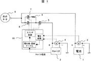
- FIG. 1 is a control block diagram of a power supply device for a vehicle according to Embodiment 1 of the present invention.
- a secondary battery 1 such as a lead storage battery and a capacitor 2 are provided as a power source, and a detection unit 3 for detecting the voltage of the secondary battery and a detection unit 4 for detecting the voltage of the capacitor are provided.
- a charge / discharge control device a discharge cutoff MOSFET 5, a charge cutoff MOSFET 6, a limit charge MOSFET 7 and a charge current limit resistor 8 are provided.
- a vehicle alternator 9 that serves as a power source for charging.
- a MOSFET switch control circuit 10 and a capacitor temperature detection means (not shown) for performing charge / discharge control are provided.
- a discharge cutoff MOSFET 5 and a charge cutoff MOSFET 6 are connected in series to the capacitor 2 in a positive supply path from the capacitor 2 to the secondary battery 1. Further, a series body of the limiting charging MOSFET 7 and the current limiting resistor 8 is connected in parallel to the charging cutoff MOSFET 6.
- the discharge cutoff MOSFET 5 is connected so that the body diode is opposite to the discharge direction of the capacitor 2, and the charge cutoff MOSFET 6 and the limited charge MOSFET 7 are such that the charge direction to the capacitor 2 and the body diode are opposite. Connected to be.
- the MOSFET switch control circuit 10 first detects the voltage of the capacitor 2 and the voltage of the secondary battery 1 and calculates the potential difference. At the same time, the control circuit 10 takes in the temperature information of the capacitor 2. When the voltage of the capacitor 2 is lower than the voltage of the secondary battery 1 and the potential difference between the two exceeds a threshold determined depending on the temperature of the capacitor 2, a first limit control mode described below is used. Become.
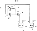
- FIG. 2 is a circuit diagram in the first limited control mode according to the first embodiment of the present invention.
- FIG. 3 is a processing flowchart combined with a second restriction control mode described later.
- the first cutoff control mode is a mode in which the charge cutoff MOSFET 6 is turned off.
- the current path during charging of the capacitor 2 in step 303 passes through the limiting charging MOSFET 7 and the current limiting resistor 8, and a current flows to the capacitor 2 through the discharging cutoff MOSFET 5. It will be. In this current path, the magnitude of the charging current is reduced by the current limiting resistor 8.
- control circuit 10 is in the second limit control mode.
- the process proceeds to step 304 in FIG.
- the charging current path is in the second limit control mode shown in FIG.
- the second limited control mode is a mode in which the limited charging MOSFET 7 is turned off.
- the limited charging MOSFET 7 When the limited charging MOSFET 7 is turned off, the current flows when charging the capacitor 2 through the charge cutoff MOSFET 6 and the discharge cutoff MOSFET 5 into the capacitor 2.
- the charging time can be shortened as compared with the control method in which the charging path is determined only by the potential difference between the capacitor 2 and the secondary battery 1.
- This embodiment is characterized in that a third restriction control mode is provided in addition to the restriction control of the first embodiment. Details are described below.
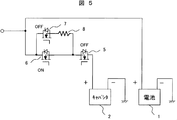
- FIG. 5 is a circuit diagram in the third limited control mode in the second embodiment of the present invention.
- FIG. 6 is a process flowchart according to the second embodiment of the present invention.
- step 601 of FIG. 6 When it is determined in step 601 of FIG. 6 that the voltage of the capacitor 2 is lower than the voltage of the secondary battery 1 and the potential difference between both exceeds a threshold (2) determined depending on the temperature of the capacitor 2 Proceeds to step 602.
- This threshold value (2) is set slightly larger than the threshold value in the first embodiment.
- step 602 as in the first embodiment, the charging cutoff MOSFET 6 is turned off as the first limit control mode. When the charging cutoff MOSFET 6 is turned off, the current path during charging of the capacitor 2 in Step 603 is reduced in magnitude by the current limiting resistor 8.
- FIG. Proceed from step 604 to step 605. Then, the current path at the time of charging the capacitor 2 in Step 606 is the second limit control mode as shown in FIG.
- the second limit control mode is a mode in which the limit charge MOSFET 7 is turned off, and the current path during charging of the capacitor 2 passes through the charge cutoff MOSFET 6 and the discharge cutoff MOSFET 5 to the capacitor 2. Flows in. In this current path, since the internal resistance of the capacitor depending on the temperature of the capacitor cell plays a role equivalent to that of the current limiting resistance, a large current does not flow at the start of charging. Others are as described in the first embodiment.
- step 604 when it is determined in step 604 that the potential difference between the two exceeds the potential difference threshold (1) depending on the cell temperature of the capacitor, the third limit control mode is entered, and the process proceeds to steps 607 and 608.
- the third limit control mode is a mode in which the limit charge MOSFET 7 and the discharge cutoff MOSFET 5 are turned off.
- the current path during charging of the capacitor 2 is similar to the second limit control mode.
- the discharge cutoff MOSFET 5 since the discharge cutoff MOSFET 5 is turned off, the voltage drops by the forward voltage drop of the body diode as compared to when the discharge cutoff MOSFET 5 is turned on. Therefore, the magnitude of the series resistance component on the capacitor side viewed from the secondary battery 1 side appears to be larger than that in the second limit control mode.
- the series resistance component of the charging path is increased by turning off the discharge cutoff MOSFET, The number of charging cases that do not require the use of the current limiting resistor 8 increases. As a result, the average charging time of the capacitor 2 can be shortened and the frequency of using the capacitor can be improved.
- an N-channel MOSFET is used for each MOSFET, and the configuration has a lower resistance.
- a P-channel MOSFET may be used for all or any one of the MOSFETs, and similar functions are provided. You may apply what can implement
- the MOSFET switch control circuit 10 includes a boost gate driver for driving the MOSFET gate.
- the step-up gate driver may be any one that can drive the gate of an N-channel MOSFET such as a charge pump type.
- the MOSFET switch control circuit has a function for monitoring the voltage of each part and a function for communicating with the host ECU. Although it is assumed that a dedicated IC or general-purpose microcomputer is used for the control circuit, any control circuit that can realize the same function may be used.
- each part of the control circuit of the MOSFET switch is assumed to be a built-in A / D converter, but any function can be used as long as the same function can be realized.
- each part voltage to monitor assumes the total voltage of secondary batteries, such as lead acid battery, a capacitor voltage, and the output of a temperature detection means, you may add and delete as needed.
- the temperature detection means is assumed to be detection by partial pressure of NTC thermistor or PTC thermistor and resistance, or detection by temperature IC, but this may be any one that can realize the same function.
- a temperature detection target a capacitor cell, a substrate, and a housing are assumed, but may be added as necessary.
- the detected temperature value is acquired by an A / D converter built in the control circuit. However, this is not limited as long as the same function can be realized.
- This embodiment is characterized in that a hybrid capacitor having an overdischarge threshold is applied as a capacitor, and in addition to the first and second embodiments, a correspondence to the lower limit voltage of the hybrid capacitor is also added. Details are described below.
- the control circuit determines whether the cell voltage of the hybrid capacitor is below a predetermined lower limit value. When the cell voltage of the hybrid capacitor is below a predetermined lower limit value, the fourth limit control mode is entered.
- the discharge cutoff MOSFET 5 is turned off. Thereby, there is no discharge from the capacitor side, and only charging is permitted. Moreover, since the current flow to the secondary battery 1 is stopped by this restriction control, it is possible to prevent cell failure due to overdischarge. When the hybrid capacitor is in an overdischarged state, gas generation or the like may occur inside, and the performance of the capacitor is significantly deteriorated. Therefore, this control is effective in improving the safety and extending the life of the hybrid capacitor.
- SYMBOLS 1 ... Secondary battery, 2 ... Capacitor, 3 ... Detection part which detects the voltage of a secondary battery, 4 ... Detection part which detects the voltage of a capacitor, 5 ... Discharge cutoff MOSFET, 6 ... Charge cutoff MOSFET, 7 ... Limiting charge MOSFET, 8... Charge current limiting resistor, 9. Alternator, 10... MOSFET switch control circuit.
Landscapes
- Engineering & Computer Science (AREA)
- Manufacturing & Machinery (AREA)
- Chemical & Material Sciences (AREA)
- Chemical Kinetics & Catalysis (AREA)
- Electrochemistry (AREA)
- General Chemical & Material Sciences (AREA)
- Power Engineering (AREA)
- Charge And Discharge Circuits For Batteries Or The Like (AREA)
- Secondary Cells (AREA)
Abstract
二次電池1とキャパシタ2とを併設した車両の電源装置において、自己放電等で低下したキャパシタ2の電圧を迅速に充電回復させ、キャパシタ2の利用頻度を上げる。 キャパシタ2と二次電池1の電流経路間に、MOSFETのような半導体スイッチを使用し、キャパシタからの放電を遮断する向きにボディダイオードを配した放電遮断スイッチを備え、この放電遮断スイッチと直列に、キャパシタ2への充電を遮断できる向きにボディダイオードを配した充電遮断スイッチ6と、この充電遮断スイッチ6と同様の向きの制限充電用スイッチ7と電流制限用抵抗8の直列体を並列に接続した構成として、前記キャパシタ2の充電時に、前記キャパシタと前記二次電池との電位差および前記キャパシタの温度によって充電モードを切替える。
Description
本発明は、キャパシタと二次電池のハイブリッド構成による車両の電源装置構成およびその制御方法に関する。
環境問題への配慮や、国が定める燃費基準の強化を背景に、各自動車メーカは低環境負荷仕様の自動車の開発に力を入れている。内燃機関と電動機を組み合わせたハイブリッド自動車や、化石燃料を使用せず、電力だけで駆動する電気自動車などがその代表例である。また、アイドルストップシステムのように、既存のガソリン自動車に新しい燃費向上機能を追加することで燃費対策を講じているものもある。
上記のように、様々な低環境負荷仕様の自動車が開発される中、アイドルストップシステムを搭載した自動車の市場は、今後急激に伸びていくと予想される。ハイブリッド車や電気自動車は、従来のガソリン自動車に比べて低燃費ではあるが、依然として開発コストの関係で車体価格が高く、一般に広く普及するには時間がかかると見られる。
他方、アイドルストップシステムは、既存のガソリン車の車体構造を変更することなく採用可能な低燃費システムであり、ハイブリッド自動車などと比べて低コストでの開発が可能であることなどから、一般に普及し易いと予測される。
アイドルストップシステム車両は、従来のガソリン車に搭載される鉛蓄電池に加えて補助的な蓄電デバイスが併設される場合が多い。これは、アイドルストップに際して生じる以下のような問題を解消するためである。ひとつに、エンジン一時停止の状態から再始動する際に、セルモータに大電流の供給が必要であるため、鉛蓄電池のみである場合、電源電圧が瞬間的に低下し、カーナビ、オーディオなどの車載電装品がリセットしてしまう。
さらに、エンジン始動回数が格段に増えるため、鉛蓄電池への負担が増し、電池が劣化しやすくなる。これらの問題を解消するために、鉛蓄電池とこれを補助する蓄電デバイスとを併設することで、車載電装品への安定した電力供給をしつつ確実なエンジン始動性を得ることと、二次電池の劣化低減を実現している。
さらに、エンジン始動回数が格段に増えるため、鉛蓄電池への負担が増し、電池が劣化しやすくなる。これらの問題を解消するために、鉛蓄電池とこれを補助する蓄電デバイスとを併設することで、車載電装品への安定した電力供給をしつつ確実なエンジン始動性を得ることと、二次電池の劣化低減を実現している。
アイドルストップ車両に搭載される補助蓄電デバイスのひとつとしてキャパシタが知られている。キャパシタは、二次電池等と比べて出力特性に優れ、瞬間的な高出力が要求されるアイドルストップシステムには適した蓄電デバイスであると言える。
ただし、キャパシタにも欠点はある。一般的にキャパシタは二次電池に比べて自己放電が大きいため、長期間充電せずに放置するとエンジン始動不可能なレベルまで電圧が低下することがある。
キャパシタの電圧が低下している場合でも、キャパシタの代わりに鉛蓄電池等の二次電池でセルモータを駆動できるよう、両デバイスを電気的に並列接続し、どちらを使用するかを適宜スイッチで切替える手法が、特許文献1などで知られている。この特許文献1には、MOSFET等の半導体素子を用いて電気二重層キャパシタと鉛蓄電池等の二次電池との切替え回路を構成して、車両に適した電源装置を提供する方法が記載されている。
ところで、自己放電等でキャパシタの電圧が低下していても、エンジン運転中にオルタネータからの電力供給により迅速にキャパシタを充電することができれば、エンジン再始動時のキャパシタ利用頻度を上げることができる。これにより、結果的に、二次電池の負担を減らすことが可能である。
しかし通常、キャパシタを充電する際、充電開始時は電流量を制限して充電するプリチャージと呼ばれるステップを経るため、特に大容量のキャパシタを充電する場合は、充電完了までに時間がかかり、キャパシタ利用頻度を低下させてしまうという問題がある。
本発明が解決しようとする課題は、上記のような二次電池とキャパシタとを併設した車両の電源装置において、キャパシタの充電を迅速に行い、自己放電などによって低下したキャパシタ電圧を回復させ、キャパシタの利用頻度を向上させることにある。
特に、大容量キャパシタを充電する際、従来のように電流量を制限した充電では充電完了までに長時間を要してしまう。
本発明は、より迅速にキャパシタを充電して、キャパシタ利用頻度を増すことで、結果として鉛蓄電池等の二次電池の負担を減らすことができる車両の電源装置を提供することを目的とする。
本発明はその一面において、エンジン動力や車両減速エネルギによって発電する発電機と、鉛蓄電池等の二次電池と、キャパシタと、二次電池の電圧を検出する検出部と、キャパシタの電圧を検出する検出部とを備え、前記発電機の出力回路を、充電遮断用スイッチング素子と、放電遮断用スイッチング素子とを介して前記キャパシタに接続した車両の電源装置において、前記キャパシタの温度を検出する検出部と、電流抑制機能付充電遮断用スイッチング素子とを備え、前記二次電池と前記キャパシタの電位差および前記キャパシタの温度に基づいて、前記キャパシタを充電する経路を、前記充電遮断用スイッチング素子または前記電流抑制機能付充電遮断用スイッチング素子を経由するように切替える切替手段を備えたことを特徴とする。
本発明の望ましい実施態様においては、前記切替手段は、前記キャパシタの電圧が前記二次電池の電圧よりも低く、かつ両者の電位差が、前記キャパシタの温度によって変動する規定値以下の場合、前記キャパシタを充電する経路を、前記充電遮断用スイッチング素子経由とし、前記両者の電位差が、前記キャパシタの温度によって変動する規定値を越えている場合、前記電流抑制機能付充電遮断用スイッチング素子を経由させる。
本発明のもうひとつの望ましい実施態様においては、前記切替手段は、
(1)前記キャパシタの電圧が前記二次電池の電圧よりも低く、かつ両者の電位差が、前記キャパシタの温度によって変動する規定値以下の場合、前記キャパシタを充電する経路を、前記充電遮断用スイッチング素子経由とし、
(2)前記両者の電位差が、前記キャパシタの温度によって変動する規定値を越え、前記キャパシタの温度によって変動する第2の判定値以下の場合、オンした前記充電遮断用スイッチング素子経由でかつオフ状態にある前記放電遮断用スイッチング素子を経由させ、(3)前記両者の電位差が、前記キャパシタの温度によって変動する規定値を越え、かつ前記キャパシタの温度によって変動する第2の判定値をも越えている場合、前記電流抑制機能付充電遮断用スイッチング素子を経由させる。
(1)前記キャパシタの電圧が前記二次電池の電圧よりも低く、かつ両者の電位差が、前記キャパシタの温度によって変動する規定値以下の場合、前記キャパシタを充電する経路を、前記充電遮断用スイッチング素子経由とし、
(2)前記両者の電位差が、前記キャパシタの温度によって変動する規定値を越え、前記キャパシタの温度によって変動する第2の判定値以下の場合、オンした前記充電遮断用スイッチング素子経由でかつオフ状態にある前記放電遮断用スイッチング素子を経由させ、(3)前記両者の電位差が、前記キャパシタの温度によって変動する規定値を越え、かつ前記キャパシタの温度によって変動する第2の判定値をも越えている場合、前記電流抑制機能付充電遮断用スイッチング素子を経由させる。
本発明の望ましい実施態様によれば、キャパシタ充電時、キャパシタと二次電池との電位差およびキャパシタ温度を判断材料とし、これらの条件によって、充電電流を制限しない経路でキャパシタを充電できる。このため、キャパシタ充電時間の短縮が可能となり、キャパシタ利用頻度を向上させることができる。さらに、これによって、鉛蓄電池等の二次電池への負担が軽減されるので、二次電池の小型化、低価格化、長寿命化、電源装置全体の高信頼化にも効果的である。
本発明のその他の目的と特徴は、以下に述べる実施態様の中で明らかにする。
以下、本発明の実施の形態を図面に基づいて説明する。
図1は、本発明の実施例1による車両の電源装置の制御構成図である。
本実施例の構成は、まず、電源として、鉛蓄電池などの二次電池1とキャパシタ2を備え、これら二次電池の電圧を検出する検出部3、キャパシタの電圧を検出する検出部4を設けている。また、充放電制御用デバイスとして、放電遮断用MOSFET5、充電遮断用MOSFET6、および制限充電用MOSFET7と充電電流制限用の抵抗8を備えている。さらに、充電用の電源となる車両のオルタネータ9がある。そして、充放電制御を実行するための、MOSFETスイッチの制御回路10およびキャパシタの温度検出手段(図示せず)を備えている。
電力経路においては、キャパシタ2から二次電池1へのプラス側の供給経路において、キャパシタ2に対して、放電遮断用MOSFET5と充電遮断用MOSFET6が直列に接続されている。また、制限充電用MOSFET7と電流制限用抵抗8の直列体が、充電遮断用MOSFET6に並列に接続された構成となっている。
放電遮断用MOSFET5は、ボディダイオードがキャパシタ2の放電方向と逆向きとなるように接続され、充電遮断用MOSFET6と制限充電用MOSFET7は、キャパシタ2への充電方向とボディダイオードの向きが逆向きとなるように接続されている。
次に、本実施例の制御方法について述べる。
通常状態においては、放電遮断用MOSFET5、充電遮断用MOSFET6、制限充電用MOSFET7はいずれもオンの状態となっている。
電源装置起動時、はじめにMOSFETスイッチ制御回路10は、キャパシタ2の電圧と、二次電池1の電圧とを検出し、その電位差を計算する。同時に制御回路10は、キャパシタ2の温度情報を取り込む。キャパシタ2の電圧が、二次電池1の電圧よりも低く、かつ両者の電位差が、キャパシタ2の温度に依存して決まる閾値を越えている場合は、次に説明する第1の制限制御モードとなる。
図2は、本発明の実施例1における第1の制限制御モードでの回路図である。
図3は、後述する第2の制限制御モードと併せた処理フローチャートである。
図3のステップ301において、キャパシタ2の電圧が、二次電池1の電圧よりも低く、かつ両者の電位差が、キャパシタ2の温度に依存して決まる閾値(1)を越えていると判定した場合は、ステップ302に進む。ステップ302において、第1の制限制御モードとして、充電遮断用MOSFET6をオフするモードとなる。この充電遮断用MOSFET6がオフとなると、ステップ303のキャパシタ2の充電時の電流経路は、制限充電用MOSFET7および電流制限用抵抗8を通過し、放電遮断用MOSFET5を経てキャパシタ2へと電流が流れることとなる。この電流経路では、電流制限用抵抗8によって、充電電流の大きさが低減される。
本第1の制限制御モードにより、自己放電などにより電圧が低下しているキャパシタを充電する際、充電電流量を低減できるため、大電流が流れ込むことによるキャパシタのセルの故障や劣化を抑制することができる。
次に、制御回路10が第2の制限制御モードとなる場合について説明する。キャパシタ2の電圧が二次電池1の電圧よりも低く、かつ両者の電位差が、キャパシタの温度に依存して決まる閾値以下である場合、図3のステップ304に進み、ステップ305でのキャパシタ2の充電電流経路は、図4に示す第2の制限制御モードとなる。
第2の制限制御モードとしては、制限充電用MOSFET7をオフするモードとなる。
この制限充電用MOSFET7がオフされると、キャパシタ2の充電時の電流経路は、充電遮断用MOSFET6および放電遮断用MOSFET5を経てキャパシタ2へと電流が流れ込むこととなる。この電流経路では、前記第1の制限制御モードに比べると電流制限抵抗等がないが、キャパシタセルの温度に依存するキャパシタの内部抵抗が電流制限抵抗と同等の役割を果たすため、充電開始時に大電流が流れ込むことはない。
この制限充電用MOSFET7がオフされると、キャパシタ2の充電時の電流経路は、充電遮断用MOSFET6および放電遮断用MOSFET5を経てキャパシタ2へと電流が流れ込むこととなる。この電流経路では、前記第1の制限制御モードに比べると電流制限抵抗等がないが、キャパシタセルの温度に依存するキャパシタの内部抵抗が電流制限抵抗と同等の役割を果たすため、充電開始時に大電流が流れ込むことはない。
キャパシタの充電が進むと、セル自体の発熱によりキャパシタの内部抵抗は減少してくる。しかし、充電と同時にキャパシタの電位が上昇し、二次電池との電位差が少なくなるため、充電でキャパシタに流れ込んでくる電流値の急激な増加は抑制され、キャパシタセルを故障させることはない。
このように、自己放電などにより電圧が低下しているキャパシタを充電する際、電池とキャパシタの電位差が、キャパシタの温度によって変動する電位差閾値以下であれば、キャパシタの内部抵抗が規定値よりも大きいと判断できる。したがって、電流制限用抵抗を通さずに充電できる。このため、キャパシタ2と二次電池1との電位差だけで充電経路を判定する制御方法に比べると充電時間の短縮が可能である。
本実施例では、実施例1の制限制御に追加して、第3の制限制御モードを設けたことが特徴である。以下にその詳細を述べる。
図5は、本発明の実施例2における第3の制限制御モードでの回路図である。
図6は、本発明の実施例2における処理フローチャートである。
図6のステップ601において、キャパシタ2の電圧が、二次電池1の電圧よりも低く、かつ両者の電位差が、キャパシタ2の温度に依存して決まる閾値(2)を越えていると判定した場合は、ステップ602に進む。この閾値(2)は、実施例1における閾値よりも若干大きく設定してある。ステップ602においては、実施例1と同様に、第1の制限制御モードとして、充電遮断用MOSFET6をオフするモードとなる。この充電遮断用MOSFET6がオフとなると、ステップ603のキャパシタ2の充電時の電流経路は、電流制限用抵抗8によって、充電電流の大きさが低減される。
本第1の制限制御モードにより、自己放電などにより電圧が低下しているキャパシタを充電する際、充電電流量を低減できるため、大電流が流れ込むことによるキャパシタのセルの故障や劣化を抑制することができることは、実施例1と同じである。
次に、制御回路10が第2の制限制御モードとなる場合について説明する。キャパシタ2の電圧が二次電池1の電圧よりも低く、かつ両者の電位差が、キャパシタの温度に依存して決まる閾値(1)(実施例1に同じ)以下である場合には、図6のステップ604からステップ605に進む。そして、ステップ606でのキャパシタ2の充電時の電流経路は、図4に示したような第2の制限制御モードとなる。
第2の制限制御モードは、前述したように、制限充電用MOSFET7をオフするモードであり、キャパシタ2の充電時の電流経路は、充電遮断用MOSFET6および放電遮断用MOSFET5を経てキャパシタ2へと電流が流れ込む。この電流経路では、キャパシタセルの温度に依存するキャパシタの内部抵抗が電流制限抵抗と同等の役割を果たすため、充電開始時に大電流が流れ込むことはない。その他は、実施例1で述べたとおりである。
次に、第3の制限制御モードについて説明する。
図6において、ステップ604で、前記両者の電位差が、キャパシタのセル温度に依存する電位差閾値(1)を超えていると判定すると、第3の制限制御モードとなり、ステップ607,608へ移行する。
第3の制限制御モードとしては、制限充電用MOSFET7および放電遮断用MOSFET5をオフするモードとなる。この場合、キャパシタ2の充電時の電流経路は、前記第2の制限制御のモードと似ている。しかし、放電遮断用MOSFET5がオフされていることから、放電遮断用MOSFET5がオンされている時に比べ、そのボディダイオードの順方向電圧降下の分だけ電圧が下がる。したがって、二次電池1側からみたキャパシタ側の直列抵抗成分の大きさは、前記第2の制限制御モードよりも大きく見える。
本制限制御を追加することにより、実施例1では第1の制限制御モードで充電しなければならない状況であっても、放電遮断用MOSFETをオフすることで充電経路の直列抵抗成分を増加させ、電流制限用抵抗8を使用しないで済む充電ケースが増える。結果としてキャパシタ2の平均充電時間を短縮させ、キャパシタ利用頻度を向上できる。
以上の実施例においては、各MOSFETにNチャネルMOSFETを使用し、より低抵抗な構成としたが、各MOSFETのすべてもしくはいずれか1つにPチャネルMOSFETを使用しても構わないし、同様の機能を実現できるものを適用しても構わない。
また、放電遮断用MOSFET5、充電遮断用MOSFET6、制限充電用MOSFET7にNチャネルMOSFETを使用し、MOSFETスイッチの制御回路10内にMOSFETのゲート駆動用の昇圧型ゲートドライバを備えているものを想定している。しかし、昇圧型ゲートドライバはチャージポンプ型等NチャネルMOSFETのゲート駆動可能なものであれば構わない。
MOSFETスイッチの制御回路には、前記ゲート駆動機能に加えて、各部電圧の監視機能、上位ECUへの通信機能等を備える。制御回路には専用のICや汎用マイコンを使用することを想定しているが、同様の機能が実現できるものであれば構わない。
MOSFETスイッチの制御回路の各部の電圧の監視機能は、内蔵したA/Dコンバータを想定しているが、同様の機能が実現できるものであれば構わない。また、監視する各部電圧は、鉛蓄電池等の二次電池の総電圧、キャパシタ電圧、温度検出手段の出力を想定しているが、必要に応じて追加、削除しても構わない。
温度検出手段は、NTCサーミスタもしくはPTCサーミスタと抵抗の分圧による検出や温度ICによる検出を想定しているが、これも同様の機能が実現できるものであれば構わない。温度検出の対象としては、キャパシタセル、基板、筐体を想定しているが、必要に応じて追加しても構わない。また、検出した温度値は、制御回路に内蔵したA/Dコンバータにより取得することを想定しているが、これも同様の機能が実現できるものであれば構わない。
本実施例では、キャパシタとして過放電閾値を持つハイブリッドキャパシタを適用し、実施例1および実施例2に加えて、ハイブリッドキャパシタの下限電圧への対応も追加したことが特徴である。以下にその詳細を述べる。
制御回路が、ハイブリッドキャパシタのセル電圧が所定の下限値を下回っているかどうかを判定する。ハイブリッドキャパシタのセル電圧が所定の下限値を下回っていた場合は、第4の制限制御モードになる。
第4の制限制御としては、放電遮断用MOSFET5をオフとする。これにより、キャパシタ側からの放電はなくなり、充電のみが許可される。また、本制限制御により、二次電池1への電流の流れ込みが停止されるため、過放電によるセルの故障を防止できる。ハイブリッドキャパシタは過放電の状態になると、内部でガス発生等が生じることがあり、キャパシタの性能が著しく劣化するため、本制御はハイブリッドキャパシタの、安全性向上および長寿命化に効果的である。
以上、本発明の実施例について説明したが、本発明は、これらの実施例に限定されるものではない。
1…二次電池、2…キャパシタ、3…二次電池の電圧を検出する検出部、4…キャパシタの電圧を検出する検出部、5…放電遮断用MOSFET、6…充電遮断用MOSFET、7…制限充電用MOSFET、8…充電電流制限用の抵抗、9…オルタネータ、10…MOSFETスイッチ制御回路。
Claims (10)
- エンジン動力や車両減速エネルギによって発電する発電機と、鉛蓄電池等の二次電池と、キャパシタと、二次電池の電圧を検出する検出部と、キャパシタの電圧を検出する検出部とを備え、
前記発電機の出力回路を、充電遮断用スイッチング素子と、放電遮断用スイッチング素子とを介して前記キャパシタに接続した車両の電源装置において、前記キャパシタの温度を検出する検出部と、電流抑制機能付充電遮断用スイッチング素子とを備え、前記二次電池と前記キャパシタの電位差および前記キャパシタの温度に基づいて、前記キャパシタを充電する経路を、前記充電遮断用スイッチング素子または前記電流抑制機能付充電遮断用スイッチング素子を経由するように切替える切替手段を備えたことを特徴とする車両の電源装置。 - 請求項1において、前記電流抑制機能付充電遮断用スイッチング素子は、スイッチング素子と充電電流制限用の抵抗の直列回路を備えたことを特徴とする車両の電源装置。
- 請求項1において、前記切替手段は、前記キャパシタの電圧が前記二次電池の電圧よりも低く、かつ両者の電位差が、前記キャパシタの温度によって変動する規定値以下の場合、前記キャパシタを充電する経路を、前記充電遮断用スイッチング素子経由とし、前記両者の電位差が、前記キャパシタの温度によって変動する規定値を越えている場合、前記電流抑制機能付充電遮断用スイッチング素子を経由させることを特徴とする車両の電源装置。
- 請求項1において、前記切替手段は、
(1)前記キャパシタの電圧が前記二次電池の電圧よりも低く、かつ両者の電位差が、前記キャパシタの温度によって変動する規定値以下の場合、前記キャパシタを充電する経路を、前記充電遮断用スイッチング素子経由とし、
(2)前記両者の電位差が、前記キャパシタの温度によって変動する規定値を越え、前記キャパシタの温度によって変動する第2の判定値以下の場合、オンした前記充電遮断用スイッチング素子経由でかつオフ状態にある前記放電遮断用スイッチング素子を経由させ、
(3)前記両者の電位差が、前記キャパシタの温度によって変動する規定値を越え、かつ前記キャパシタの温度によって変動する第2の判定値をも越えている場合、前記電流抑制機能付充電遮断用スイッチング素子を経由させることを特徴とする車両の電源装置。 - 請求項1において、前記キャパシタの電圧が、その上限電圧よりも上回ったとき、前記充電遮断用スイッチング素子をオフする充電阻止手段を備えたことを特徴とする車両の電源装置。
- 請求項1において、前記キャパシタは、正極材および負極材に異なる電極材料を用いたハイブリッド構成であって、負極にリチウムイオンがドープされたハイブリッドキャパシタであることを特徴とする車両の電源装置。
- 請求項6において、前記ハイブリッドキャパシタの電圧が、過放電電圧閾値を下回ったとき、前記放電遮断用スイッチング素子をオフする放電阻止手段を備えたことを特徴とする車両の電源装置。
- 請求項1において、前記スイッチング素子の制御用に1つの判別制御手段を備えたことを特徴とする車両の電源装置。
- 請求項1において、前記スイッチング素子は、それぞれ、MOSFETであることを特徴とする車両の電源装置。
- エンジン動力や車両減速エネルギによって発電する発電機と、鉛蓄電池等の二次電池と、キャパシタと、二次電池の電圧を検出する検出部と、キャパシタの電圧を検出する検出部とを備え、前記発電機の出力回路を、充電遮断用スイッチング素子と、放電遮断用スイッチング素子とを介して前記キャパシタに接続した車両の電源装置制御方法において、前記キャパシタの温度を検出するステップと、前記二次電池と前記キャパシタの電位差および前記キャパシタの温度に基づいて、前記キャパシタを充電する経路を、前記充電遮断用スイッチング素子または電流抑制機能付きの充電遮断用スイッチング素子を経由するように切替えるステップを備えたことを特徴とする車両の電源装置制御方法。
Applications Claiming Priority (2)
| Application Number | Priority Date | Filing Date | Title |
|---|---|---|---|
| JP2008-212356 | 2008-08-21 | ||
| JP2008212356A JP5104648B2 (ja) | 2008-08-21 | 2008-08-21 | 車両の電源装置およびその制御方法 |
Publications (1)
| Publication Number | Publication Date |
|---|---|
| WO2010021076A1 true WO2010021076A1 (ja) | 2010-02-25 |
Family
ID=41706970
Family Applications (1)
| Application Number | Title | Priority Date | Filing Date |
|---|---|---|---|
| PCT/JP2009/003109 Ceased WO2010021076A1 (ja) | 2008-08-21 | 2009-07-03 | 車両の電源装置およびその制御方法 |
Country Status (2)
| Country | Link |
|---|---|
| JP (1) | JP5104648B2 (ja) |
| WO (1) | WO2010021076A1 (ja) |
Cited By (1)
| Publication number | Priority date | Publication date | Assignee | Title |
|---|---|---|---|---|
| EP3893318A4 (en) * | 2020-02-28 | 2021-12-22 | Dongguan Amperex Technology Limited | BATTERY PACK MANAGEMENT SYSTEM, BATTERY PACK, VEHICLE AND MANAGEMENT PROCEDURES |
Families Citing this family (11)
| Publication number | Priority date | Publication date | Assignee | Title |
|---|---|---|---|---|
| JP5664310B2 (ja) * | 2011-02-10 | 2015-02-04 | 新神戸電機株式会社 | 直流電源装置 |
| WO2013115034A1 (ja) * | 2012-01-31 | 2013-08-08 | 三洋電機株式会社 | 車両用の電源装置及びこの電源装置を備える車両 |
| CN103311965B (zh) * | 2012-03-06 | 2016-02-24 | 北京联动天翼科技有限公司 | 并联电池组充放电智能管理装置和方法 |
| CN103311966B (zh) * | 2012-03-06 | 2016-06-22 | 北京联动天翼科技有限公司 | 应用于并联电池组的电池自适应控制装置和方法 |
| WO2014068865A1 (ja) * | 2012-10-29 | 2014-05-08 | 三洋電機株式会社 | 車載用蓄電システム |
| JP6468758B2 (ja) * | 2014-08-27 | 2019-02-13 | ルネサスエレクトロニクス株式会社 | 半導体装置 |
| JP7441692B2 (ja) * | 2020-03-23 | 2024-03-01 | Fdk株式会社 | 電池電圧均等化装置 |
| TWI743763B (zh) * | 2020-04-28 | 2021-10-21 | 低碳動能開發股份有限公司 | 車用超級電容模組的保護方法及其保護裝置 |
| CN111688506A (zh) * | 2020-07-13 | 2020-09-22 | 东风汽车股份有限公司 | 一种增程充电机到动力电池的高压配电电路及其控制方法 |
| KR20230011796A (ko) * | 2021-07-14 | 2023-01-25 | 주식회사 엘지에너지솔루션 | 배터리 장치, 배터리 관리 시스템 및 프리차지 방법 |
| CN114142567A (zh) * | 2021-12-06 | 2022-03-04 | 珠海冠宇动力电源有限公司 | 电池管理电路及电池装置 |
Citations (5)
| Publication number | Priority date | Publication date | Assignee | Title |
|---|---|---|---|---|
| JPH0767263A (ja) * | 1993-08-20 | 1995-03-10 | Sanyo Electric Co Ltd | 二次電池の過放電防止回路 |
| JP2002325377A (ja) * | 2001-04-25 | 2002-11-08 | Hitachi Ltd | 自動車電源装置 |
| JP2004056937A (ja) * | 2002-07-22 | 2004-02-19 | Nissan Motor Co Ltd | 蓄電システム |
| JP2006152820A (ja) * | 2004-11-25 | 2006-06-15 | Nissan Diesel Motor Co Ltd | 車両の電源装置 |
| JP2007336610A (ja) * | 2006-06-12 | 2007-12-27 | Power System:Kk | 蓄電素子充放電システム |
-
2008
- 2008-08-21 JP JP2008212356A patent/JP5104648B2/ja not_active Expired - Fee Related
-
2009
- 2009-07-03 WO PCT/JP2009/003109 patent/WO2010021076A1/ja not_active Ceased
Patent Citations (5)
| Publication number | Priority date | Publication date | Assignee | Title |
|---|---|---|---|---|
| JPH0767263A (ja) * | 1993-08-20 | 1995-03-10 | Sanyo Electric Co Ltd | 二次電池の過放電防止回路 |
| JP2002325377A (ja) * | 2001-04-25 | 2002-11-08 | Hitachi Ltd | 自動車電源装置 |
| JP2004056937A (ja) * | 2002-07-22 | 2004-02-19 | Nissan Motor Co Ltd | 蓄電システム |
| JP2006152820A (ja) * | 2004-11-25 | 2006-06-15 | Nissan Diesel Motor Co Ltd | 車両の電源装置 |
| JP2007336610A (ja) * | 2006-06-12 | 2007-12-27 | Power System:Kk | 蓄電素子充放電システム |
Cited By (3)
| Publication number | Priority date | Publication date | Assignee | Title |
|---|---|---|---|---|
| EP3893318A4 (en) * | 2020-02-28 | 2021-12-22 | Dongguan Amperex Technology Limited | BATTERY PACK MANAGEMENT SYSTEM, BATTERY PACK, VEHICLE AND MANAGEMENT PROCEDURES |
| JP2022525825A (ja) * | 2020-02-28 | 2022-05-20 | 東莞新能源科技有限公司 | バッテリーパック管理システム、バッテリーパック、車両及び管理方法 |
| JP7260635B2 (ja) | 2020-02-28 | 2023-04-18 | 東莞新能源科技有限公司 | バッテリーパック管理システム、バッテリーパック、車両及び管理方法 |
Also Published As
| Publication number | Publication date |
|---|---|
| JP5104648B2 (ja) | 2012-12-19 |
| JP2010051082A (ja) | 2010-03-04 |
Similar Documents
| Publication | Publication Date | Title |
|---|---|---|
| JP5104648B2 (ja) | 車両の電源装置およびその制御方法 | |
| JP5811055B2 (ja) | バッテリシステム制御装置 | |
| CN105936248B (zh) | 电源系统 | |
| EP2272722B1 (en) | Power source apparatus for vehicle | |
| JP5578014B2 (ja) | バッテリシステム制御装置 | |
| JP6613997B2 (ja) | 電源装置 | |
| US9649950B2 (en) | Power supply apparatus | |
| JP5307847B2 (ja) | 車両用電源システム | |
| CN105765198B (zh) | 电路 | |
| JP5488046B2 (ja) | 車載電源装置 | |
| JP5488169B2 (ja) | 電源装置 | |
| US10399454B2 (en) | Vehicle power supply apparatus | |
| JP5277711B2 (ja) | 電源装置及び車両用電源装置 | |
| US10119513B2 (en) | Power supply system | |
| US10677176B2 (en) | Vehicle power system | |
| JP2014018017A (ja) | バッテリシステム制御装置 | |
| JP6572621B2 (ja) | 電気回路 | |
| JP6165522B2 (ja) | 蓄電システム | |
| WO2021125193A1 (ja) | 車載電源装置の制御装置 |
Legal Events
| Date | Code | Title | Description |
|---|---|---|---|
| 121 | Ep: the epo has been informed by wipo that ep was designated in this application |
Ref document number: 09808012 Country of ref document: EP Kind code of ref document: A1 |
|
| NENP | Non-entry into the national phase |
Ref country code: DE |
|
| 122 | Ep: pct application non-entry in european phase |
Ref document number: 09808012 Country of ref document: EP Kind code of ref document: A1 |