WO2010018697A1 - 自動分析装置の状態把握方法および自動分析装置 - Google Patents
自動分析装置の状態把握方法および自動分析装置 Download PDFInfo
- Publication number
- WO2010018697A1 WO2010018697A1 PCT/JP2009/055460 JP2009055460W WO2010018697A1 WO 2010018697 A1 WO2010018697 A1 WO 2010018697A1 JP 2009055460 W JP2009055460 W JP 2009055460W WO 2010018697 A1 WO2010018697 A1 WO 2010018697A1
- Authority
- WO
- WIPO (PCT)
- Prior art keywords
- point
- automatic analyzer
- failure
- subtraction
- addition
- Prior art date
- Legal status (The legal status is an assumption and is not a legal conclusion. Google has not performed a legal analysis and makes no representation as to the accuracy of the status listed.)
- Ceased
Links
Images





Classifications
-
- G—PHYSICS
- G01—MEASURING; TESTING
- G01N—INVESTIGATING OR ANALYSING MATERIALS BY DETERMINING THEIR CHEMICAL OR PHYSICAL PROPERTIES
- G01N35/00—Automatic analysis not limited to methods or materials provided for in any single one of groups G01N1/00 - G01N33/00; Handling materials therefor
- G01N35/02—Automatic analysis not limited to methods or materials provided for in any single one of groups G01N1/00 - G01N33/00; Handling materials therefor using a plurality of sample containers moved by a conveyor system past one or more treatment or analysis stations
- G01N35/04—Details of the conveyor system
-
- G—PHYSICS
- G01—MEASURING; TESTING
- G01N—INVESTIGATING OR ANALYSING MATERIALS BY DETERMINING THEIR CHEMICAL OR PHYSICAL PROPERTIES
- G01N35/00—Automatic analysis not limited to methods or materials provided for in any single one of groups G01N1/00 - G01N33/00; Handling materials therefor
- G01N35/02—Automatic analysis not limited to methods or materials provided for in any single one of groups G01N1/00 - G01N33/00; Handling materials therefor using a plurality of sample containers moved by a conveyor system past one or more treatment or analysis stations
- G01N35/04—Details of the conveyor system
- G01N2035/0401—Sample carriers, cuvettes or reaction vessels
- G01N2035/0403—Sample carriers with closing or sealing means
- G01N2035/0405—Sample carriers with closing or sealing means manipulating closing or opening means, e.g. stoppers, screw caps, lids or covers
Definitions
- the present invention relates to an automatic analyzer status grasping method and an automatic analyzer that support analysis of a failure that has occurred in an automatic analyzer that analyzes a sample using a sample and a reagent.
- the present invention has been made in view of the above, and an object of the present invention is to provide an automatic analyzer state grasping method and an automatic analyzer that can quickly cope with a failure of the automatic analyzer.
- the method for grasping the state of the automatic analyzer according to the present invention is connected to a server via a communication network so as to be able to communicate, and uses the sample and the reagent.
- a method of grasping the state of an automatic analyzer that records the failure of an automatic analyzer that performs sample analysis on the server side, and responds to the failure when information indicating the failure is received
- the addition point is a value obtained by increasing a numerical value according to the importance of each failure.
- the predetermined value is an upper limit value of a plurality of point areas that are divided hierarchically in advance with respect to the point value of the accumulated points. It is characterized by being.
- the state analysis method of the automatic analyzer according to the present invention is based on the above invention, and when the preset expiration date has passed for each failure, the accumulated subtraction points for each failure are set as the cumulative points. A subtracting step for subtracting from the subtracting step.
- the subtraction step may be configured such that the subtraction point of the fault that has passed the expiration date is the cumulative point during the cumulative addition process in the addition step. It is characterized by subtracting from.
- the state analysis method of the automatic analyzer according to the present invention is characterized in that the subtraction step subtracts the subtraction point of the failure from the cumulative point when the expiration date has passed.
- the subtracting step checks whether or not there is a failure whose expiration date has passed every predetermined time. When a failure whose expiration date has passed is detected, a subtraction process of the failure is subtracted from the accumulated point.
- the subtracting step includes a step in which, during the subtraction process, the accumulated point after the subtraction process is the lower limit of the point area to which the accumulated point before the subtraction process belongs.
- the accumulated point after the subtraction process is set to the lower limit value of the point area.
- the automatic analyzer is an automatic analyzer that is connected to a server via a communication network so as to be able to communicate with the server and performs analysis of the sample using a sample and a reagent.
- the addition means for accumulating the addition points set in advance corresponding to the failure, and when the accumulated points accumulated by the addition means are larger than a predetermined value, the failure is And an informing means for informing that it has occurred.
- the addition point is a value obtained by increasing a numerical value in accordance with the importance of each failure.
- the predetermined value is an upper limit value of a plurality of point areas divided hierarchically in advance with respect to the point value of the accumulated points.
- the automatic analyzer subtracts a preset subtraction point for each fault from the accumulated points when a preset expiration date has passed for each fault.
- a subtracting means is provided.
- the automatic analyzer according to the present invention is characterized in that, in the above invention, the subtracting means subtracts the subtraction point of the fault that has expired from the cumulative point during the cumulative addition process. To do.
- the subtracting means subtracts the subtraction point of the failure from the cumulative point when the expiration date has passed.
- the subtracting unit checks whether there is a failure for which the expiration date has passed every predetermined time, and the expiration date is determined by the check. When an elapsed failure is detected, a subtraction point of the failure is subtracted from the accumulated point.
- the subtracting means when the subtracting process, the accumulated point after the subtracting process is below the lower limit value of the point area to which the accumulated point before the subtracting process belongs
- the accumulated points after the subtraction process are set to the lower limit value of the point area.
- an additional point is set for each failure, and every time a failure occurs, the points of the failure are cumulatively added and notified by e-mail or the like according to the cumulatively added cumulative points. There is an effect that can be grasped early.
- FIG. 1 is a schematic diagram illustrating an overall configuration of a management system according to the first embodiment.
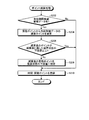
- FIG. 2 is a flowchart showing the point addition processing performed by the addition processing unit.
- FIG. 3 is a flowchart showing point subtraction processing performed by the subtraction processing unit.
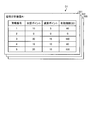
- FIG. 4 is a schematic diagram showing device information of each automatic analyzer.
- FIG. 5 is a schematic diagram illustrating alarm data information according to the first embodiment.
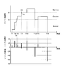
- FIG. 6 is a graph showing the transition of accumulated points at each time corresponding to FIG. 5 and the points to be added and subtracted.
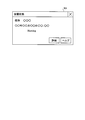
- FIG. 7 is a schematic diagram showing an example of a pop-up displayed on the screen.
- FIG. 8 is a schematic diagram illustrating alarm data information according to the second embodiment.
- FIG. 1 is a schematic diagram illustrating an overall configuration of a management system according to the first embodiment.
- FIG. 2 is a flowchart showing the point addition processing performed by the addition processing unit.
- FIG. 3 is a flowchart showing point sub
- FIG. 9 is a graph showing the transition of accumulated points at each time corresponding to FIG. 8 and the points to be added and subtracted.
- FIG. 10 is a schematic diagram illustrating alarm data information according to the third embodiment.
- FIG. 11 is a graph showing the transition of accumulated points at each time corresponding to FIG. 10 and the points to be added and subtracted.
- FIG. 1 is a schematic diagram illustrating an overall configuration of a management system according to the first embodiment.
- the management system according to the first embodiment includes automatic analyzers A1 to A3, B1, and B2 respectively disposed in a plurality of facilities, and automatic analyzers A1 to A3 via a network N. , B1, B2 and a management server 10 connected thereto.
- the automatic analyzers A1 to A3, B1, and B2 are installed in a plurality of facilities, respectively. For example, in the facility A, automatic analyzers A1 to A3 are installed, and in the facility B, automatic analyzers B1 and B2 are installed.
- the management server 10 manages the automatic analyzers A1 to A3, B1, and B2 by communicating with the automatic analyzers A1 to A3, B1, and B2 via the network N. In accordance with the contents of the transmission information transmitted from the automatic analyzers A1 to A3, B1, and B2, the management server 10 sends the transmission information to the transfer destination registered in advance for each of the automatic analyzers A1 to A3, B1, and B2. Forward.
- the management server 10 has a database 20 that stores various types of information.
- This transfer destination is a terminal device possessed by an operator of the automatic analyzers A1 to A3, B1, B2, for example, the portable terminal 50 possessed by the operator of the automatic analyzer A1 in the facility A.
- Such transfer destinations are the automatic analyzers A1 to A3 by the operators of the automatic analyzers A1 to A3, B1 and B2 when starting the analysis process in the automatic analyzers A1 to A3, B1 and B2.
- When logging in to B1 and B2 they are input by the respective operators in the automatic analyzers A1 to A3, B1 and B2.
- the management server 10 includes a control unit 11 that controls the processing operation of each component of the management server 10, an input unit 13 that inputs each instruction information, and a calculation unit that performs point calculation processing. 15, an output unit 14 for outputting information processed by the management server 10, and a transmission / reception unit 12 having a function as an interface for transmitting / receiving information according to a predetermined format via the communication network N.
- the calculation unit 15 includes an addition processing unit 16 and a subtraction processing unit 17, and each performs cumulative addition processing and subtraction processing according to instructions from the control unit 11.
- the control unit 11 creates device information D1 and alarm data information D2 to be stored in the database 20, and updates the information stored in the database 20.
- each of the automatic analyzers A1 to A3, B1, and B2 transmits information related to each of the automatic analyzers A1 to A3, B1, and B2 to the management server 10 via the network N.
- Each of the automatic analyzers A1 to A3, B1, and B2 periodically transmits connection information indicating a connection state between the management server 10 and the automatic analyzers A1 to A3, B1, and B2 to the management server 10.
- each of the automatic analyzers A1 to A3, B1, and B2 transmits state information indicating the operation state of the automatic analyzers A1 to A3, B1, and B2 itself to the management server 10.
- the status information includes information indicating that the analysis process that has been performed is completed, temperature information of the sample, the reagent, and the liquid in the reaction container.
- each of the automatic analyzers A1 to A3, B1, and B2 transmits abnormality information indicating that an abnormality has occurred in each of the automatic analyzers A1 to A3, B1, and B2 to the management server 10.
- FIG. 1 shows the structure of, for example, the automatic analyzers A1, B1 among the automatic analyzers A1 to A3, B1, B2.
- the automatic analyzers A1 and B1 dispense measuring reagents 30 and 40 that optically measure a reaction occurring in the reaction container by dispensing a reagent corresponding to the specimen and the test item into the reaction container.
- Control units 31 and 41 for controlling the processing and operation of each component part of the automatic analyzers A1 and B1, input units 32 and 42 for inputting various information, and the measurement results by the measurement mechanisms 30 and 40, the samples.
- FIG. 2 is a flowchart showing the point addition processing performed by the addition processing unit 16 in the management server 10.
- step S102 when the management server 10 receives alarm data corresponding to a failure from the automatic analyzer, the control unit 11 instructs the addition processing unit 16 to perform point addition processing (step S102: Yes).
- the addition processing unit 16 Upon receiving the alarm data, the addition processing unit 16 cumulatively adds the current addition point to the cumulative point of the corresponding automatic analyzer (step S104).
- step S106 when the accumulated points after the cumulative addition process in the apparatus state set in the preset point area exceed the upper limit value of the point area to which the cumulative points before the cumulative addition process belonged (step S106: Yes) ) To change the set device state.
- step S110: Yes If the apparatus state before the cumulative addition process is “Warning”, which is the highest state (step S110: Yes), the addition processing unit 16 notifies the person in charge by e-mail or the like without changing the apparatus state. This is notified to the control unit 11 (step S114).
- step S110: No When the device state is other than “Warning” (step S110: No), the addition processing unit 16 notifies the control unit 11 to change the set device state (step S112). Thereafter, the addition processing unit 16 notifies the control unit 11 to notify the person in charge that the device state has been changed by e-mail or the like (step S114), and warns the time, cumulative points, and expiration date when the alarm data is received. Registration in the data information D2 (step S116).
- the apparatus state when the accumulated point is 50 or less, the apparatus state is set to “Normal”, and when it is 51 to 80, “Caution” is set. Further, when the accumulated point exceeds 81, “Warning” is set, and the apparatus state to be set becomes the highest level.
- the apparatus state indicating the apparatus state is changed by the above-described three-stage point area.
- step S106 when the accumulated point subjected to the cumulative addition process does not exceed the upper limit value of the point area to which the cumulative point before the cumulative addition process belongs (step S106: No), the addition processing unit 16 is set. It is determined whether or not the device status is “Warning” (step S108). Here, if the set device state is “Warning” (step S108: Yes), the process proceeds to step S114, and the person in charge is informed that a failure has occurred at the highest level of the failure occurrence state of the device. Is notified to the control unit 11.
- step S108 the addition processing unit 16 proceeds to step S116 and registers the time, cumulative point, and expiration date when alarm data is received in the alarm data information D2. To do. By performing this point addition process every time alarm data is received, points are added each time a failure occurs.
- FIG. 3 is a flowchart showing point subtraction processing performed by the subtraction processing unit 17 in the management server 10.
- the point subtraction process is performed when the point addition process is performed. That is, the point subtraction process is performed when the management server 10 receives alarm data from the automatic analyzer.
- the control unit 11 instructs the subtraction processing unit 17 to perform subtraction processing.
- the subtraction processing unit 17 determines whether or not there is alarm data whose expiration date has passed from the data registered in the alarm data information D2 (step S202).
- the subtraction processing unit 17 subtracts the subtraction point of the alarm data from the accumulated point (step S204).
- the subtraction processing unit 17 determines whether or not the accumulated points after the subtraction process are equal to or greater than the lower limit value of the point area to which the accumulated points before the subtraction process belonged (step S206).
- step S206: No When the accumulated points after the subtraction process are below the lower limit value of the point area to which the accumulated points before the subtraction process belonged (step S206: No), the subtraction processing unit 17 accumulates the points after the subtraction before the subtraction process.
- the lower limit value of the point area to which the point belongs is set (step S208), and the time when the alarm data is received and the accumulated point after the subtraction process are registered in the alarm data information D2 (step S210).
- step S206: Yes when the accumulated point after the subtraction process is greater than or equal to the lower limit value of the point area to which the accumulated point before the subtraction process belonged in step S206 (step S206: Yes), the subtraction processing unit 17 proceeds to step S210.
- the time when the alarm data is received and the accumulated points after the subtraction process are registered in the alarm data information D2.
- step S202 If there is no alarm data whose expiration date has passed in step S202 (step S202: No), the subtraction processing unit 17 proceeds to step S210 and registers the time and cumulative points at which the subtraction processing was performed.
- the points are subtracted by performing the above-described point subtraction process every time alarm data is received.
- the accumulation point obtained by performing the accumulation addition process performed at the substantially same timing is used for the accumulation point used for subtraction. For this reason, it is preferable to perform the subtraction after the cumulative addition process. Further, the cumulative addition process may be performed using the cumulative points obtained by performing the subtraction process.
- the device information D1 is an information table indicating an alarm number corresponding to a failure of each of the automatic analyzers A1 to A3, an addition point, a subtraction point, and an expiration date for the alarm number.
- FIG. 4 shows an information table 301 of the automatic analyzer A1.
- the information table 302 for the automatic analyzer A2, the information table 303 for the automatic analyzer A3, and the information table for each automatic analyzer are created.
- the addition point, subtraction point, and expiration date are determined in consideration of the effect on the device, etc.
- the value of the addition point increases as the effect on the device increases, and the expiration date has an effect on the device. The larger the value is, the longer the time limit is set.
- an addition point is output from the alarm number corresponding to the alarm data of the failure according to an instruction from the control unit 11, and the addition processing unit 16 performs a cumulative addition process using the addition point. If there is alarm data whose expiration date has passed, a subtraction point of the alarm number is output according to an instruction from the control unit 11, and subtraction processing is performed by the subtraction processing unit 17.
- FIG. 5 is a diagram showing a list of data registered in the alarm data information D2.
- FIG. 5 shows an alarm data information table 401 of the automatic analyzer A1 at the facility A, and an alarm data information table 402 of the automatic analyzer A2 and an alarm data information table 403 of the automatic analyzer A3 are also created.
- the alarm data information table 401 includes the time at which alarm data is received, the alarm number of the alarm data received at that time, the applicable addition or subtraction point, the expiration date of the alarm data, the cumulative point, The device status representing the status is registered.
- the alarm number corresponds to that in FIG. 4, and R indicates that the subtraction process is performed.
- a point having a minus ( ⁇ ) in front of a number indicates a subtraction point.
- times T1 to T5, T7, T10, and T15 are times when alarm data is received and cumulative addition processing and subtraction processing are performed.
- Time T0 is device startup time
- times T13 and T19 are manual. Is the time when the device state is changed.
- the person in charge of the device confirms the alarm data, it is possible to manually change the accumulated points. If the accumulated points are changed manually, the expiration date of the data registered so far becomes invalid.
- the expiration date of the alarm data at times T3, T7, and T10 is invalidated by the manual change at time T13
- the expiration date of the alarm data at time T15 is invalidated by the manual change at time T19.
- the subtraction point at T7 is subtracted by the subtraction process because the accumulated point falls below the lower limit value of the point area corresponding to the device state due to the subtraction process subtracting 5 points, which is originally a numerical value in parentheses. It is shown that the subtracted points are 4 points.
- the person in charge of the apparatus is notified that a failure has occurred by e-mail or the like.
- FIG. 6 is a graph showing the transition of the accumulated points at each time corresponding to FIG. 5 and the points to be added and subtracted.
- the upper part of FIG. 6 is a graph relating to time and accumulated points, and the lower part shows a graph of addition points to be added to time and subtraction points to be subtracted, and the upper part and the lower part coincide with each other.
- the value of the cumulative point P1 is originally obtained by the cumulative addition process and the subtraction process, but the apparatus state is changed to “Warning” by the cumulative addition process. Since the value cannot be obtained in the point area of “Caution”, the apparatus state is set to the lower limit value P2 of the point area of “Warning” in the subtraction process.
- the person in charge of the device confirms the alarm data and indicates that the device state is changed to the lower device state.
- FIG. 7 shows a pop-up displayed on the screen when a person in charge accesses through the network N in addition to the mobile terminal 50 from the base station 60 as a method for notifying when the apparatus state is changed due to an increase in accumulated points.
- An example is shown.
- the device status is changed, a model as shown in FIG. 7, the date and time when the device status is changed, and a notification screen W1 indicating the changed device status are displayed through the network N.
- the person in charge of the apparatus and the person in charge of the manufacturer can confirm the display through the network N from the management server 10, so that it is possible to take early measures against a failure that occurs in the automatic analyzer.
- the person in charge on the client side is notified, and at that point, the person in charge of the manufacturer is contacted.
- the person in charge of the manufacturer will investigate after the contact to confirm the magnitude of the failure and take countermeasures, so the time until the client contacts and the person in charge of the manufacturer It took time to arrive at the site and to confirm the failure.
- the first embodiment by giving points to each failure, it becomes possible to confirm the size of the failure early, and the person in charge of the manufacturer can also confirm the alarm information early. Therefore, it is possible to devise countermeasures against failures at an early stage.
- the points by setting an expiration date for each failure, not only will the points accumulate due to the occurrence of the failure, but what will greatly affect the device will remain as data for a long time, so the device status will change due to the failure point having a relatively small impact It is difficult to adjust the accumulated point.
- FIG. 8 shows alarm data information D2 according to the second exemplary embodiment.
- the reception time of alarm data indicating a failure is the same as that in FIG. 5 of the first embodiment and the same failure, and the alarm data for which the expiration date has passed is subtracted when the expiration date has passed.
- FIG. 9 shows a graph corresponding to FIG.
- the upper part of FIG. 9 is a graph relating to time and accumulated points, and the lower part shows a graph of addition points to be added to the time and subtraction points to be subtracted. The upper part and the lower part coincide with each other.
- the subtraction process is performed at times T6, T8, T9, and T18, which are the expiration times of the respective alarm data. Each time corresponds to the expiration date of previously registered alarm data.
- T13 and T19 the person in charge of the device has confirmed the alarm data and indicates that the device state has been changed to a lower device state.
- the expiration date of the alarm data at times T3, T7 and T10 is invalidated by manual change at time T13.
- T4 and T10 when the accumulated points shift to the upper point area, the person in charge of the apparatus is notified that a failure has occurred by mail or the like.
- a point with a minus ( ⁇ ) in front of a number indicates a subtraction point.
- the subtraction process is performed when the expiration date has passed, it is possible to process the accumulated points more strictly.
- Embodiment 1 since the subtraction process is performed when the cumulative addition process is performed, the time and labor for the process are reduced, but the subtraction process is not performed unless data indicating a failure is received. When no failure occurs and the device is stable, the accumulated points remain without being subtracted.
- the subtraction process since the subtraction process is performed when the expiration date has passed, the subtraction process is performed even when a failure does not occur and the apparatus is stable, and the accumulated points are processed more appropriately. Make it possible.
- FIG. 10 shows alarm data information D2 according to the third embodiment.
- the reception time of alarm data indicating a failure is the same as that in FIG. 5 of the first embodiment and the same failure.
- the predetermined time is set to 30 minutes, and it is checked whether there is alarm data that has expired every 30 minutes, and there is alarm data that has expired. Subtract processing.
- the subtraction process is performed at times T1, T4, T6, T8, T11, T12, T14, T16, and T17.
- Each time is subtracted by checking whether there is alarm data whose expiration date has passed every 30 minutes, with time T1 as the subtraction start time.
- the manual change at time T13 invalidates the expiration date of the alarm data at times T3, T7 and T10, and the manual change at time T19 invalidates the expiration date of the alarm data at time T15.
- the person in charge of the apparatus is notified that a failure has occurred by mail or the like. Note that a notification that the apparatus state is “Warning” may also be made when the time T11 is subtracted.
- a point having a minus ( ⁇ ) in front of a number indicates a subtraction point.
- FIG. 11 a graph corresponding to FIG. 10 is shown in FIG.
- the upper part of FIG. 11 is a graph relating to time and accumulated points, and the lower part shows a graph of addition points to be added to the time and subtraction points to be subtracted.
- the upper part and the lower part coincide with each other.
- the lower graph in FIG. 11 shows that the subtraction process is performed at times divided at equal intervals except for the times T13 and T19 when the apparatus state is manually changed. Further, the manual change of the accumulated points at times T13 and T19 is performed at the timing of the person in charge.
- the management server and the automatic analyzer since the subtraction process is periodically performed, the management server and the automatic analyzer always keep the latest accumulated point information by adjusting the time for periodic transmission and reception between the management server and the automatic analyzer. Allows management.
- the cumulative addition process and the subtraction process may be performed by the calculation unit of each automatic analyzer, and information such as cumulative points may be transmitted to the server.
- the calculation unit 37 in the automatic analyzer A1 may store the results obtained by performing the cumulative addition process and the subtraction process in the storage unit 34, and may transmit the data obtained to the management server 10.
- the present invention is not limited to the above-described first to third embodiments, and may include various embodiments and the like not described herein, and within a scope that does not depart from the technical idea specified by the claims. Various design changes and the like can be made.
- the automatic analyzer according to the present invention is useful for early response to a failure of the automatic analyzer, and is particularly suitable for a management system having a management server connected to the automatic analyzer via a network. ing.
Landscapes
- Physics & Mathematics (AREA)
- Health & Medical Sciences (AREA)
- Life Sciences & Earth Sciences (AREA)
- Chemical & Material Sciences (AREA)
- Analytical Chemistry (AREA)
- Biochemistry (AREA)
- General Health & Medical Sciences (AREA)
- General Physics & Mathematics (AREA)
- Immunology (AREA)
- Pathology (AREA)
- Automatic Analysis And Handling Materials Therefor (AREA)
Abstract
各障害に対応する警報データに対して加算ポイントと、減算ポイント及び有効期限を設定して、管理サーバ(10)が障害を示す情報を自動分析装置から受信した場合に、受信した障害に対応する警報データの加算ポイントを累積加算する累積加算ステップと、有効期限が経過した警報データの減算ポイントを減算する減算ステップとを含む自動分析装置の状態把握方法によって、累積加算処理及び減算処理された累積ポイントを確認することで早期に自動分析装置の状態を把握することを可能とする。
Description
本発明は、検体と試薬とを用いて検体の分析を行う自動分析装置に発生した障害の解析を支援する自動分析装置の状態把握方法および自動分析装置に関するものである。
従来、分析結果の信頼性を高めるため、ネットワークなどの通信接続手段を介して複数の自動分析装置と管理サーバとを接続し、接続した自動分析装置と管理サーバの間で通信を行うことによって、自動分析装置の障害情報を送受信して状態を把握する管理システムが提案されている(たとえば、特許文献1参照)。この管理システムでは、ネットワークを介して遠隔制御が可能であり、現地でサービス担当者がサポートにあたり、遠隔地から技術担当者が遠隔制御して障害の復旧にあたることを可能としている。
しかしながら、従来の技術では、自動分析装置に障害が発生した場合、ユーザが先ずサポート担当者に連絡を取る必要があり、ユーザが障害を発見するまで障害に対する対策はとっていなかった。そのため、連絡を取るタイミングによっては、障害が発生してから時間が経過してしまう可能性があった。また、障害の重要度の情報がないために、連絡を取った後に調査する必要があり、障害の大きさを把握することにも時間を要していた。
本発明は、上記に鑑みてなされたものであって、自動分析装置の障害に対して早期に対応できる自動分析装置の状態把握方法および自動分析装置を提供することを目的とする。
上述した課題を解決し、目的を達成するために、本発明にかかる自動分析装置の状態把握方法は、通信ネットワークを介してサーバと通信可能に接続されており、検体と試薬とを用いて前記検体の分析を行う自動分析装置の障害をサーバ側で記録して該自動分析装置の状態を把握する自動分析装置の状態把握方法であって、障害を示す情報を受信した場合に当該障害に対応して予め設定された加算ポイントを累積加算処理する加算ステップと、前記加算ステップによって累積加算された累積ポイントが所定値に比して大きい場合に、障害が発生した旨を報知する報知ステップと、を含むことを特徴とする。
また、本発明にかかる自動分析装置の状態把握方法は、上記の発明において、前記加算ポイントは、各障害の重要度に応じて数値を大きくした値であることを特徴とする。
また、本発明にかかる自動分析装置の状態把握方法は、上記の発明において、前記所定値は、前記累積ポイントのポイント値に対して予め階層的に分割された複数のポイント領域の各上限値であることを特徴とする。
また、本発明にかかる自動分析装置の状態把握方法は、上記の発明において、各障害毎に予め設定された有効期限を経過した場合に、予め設定された各障害毎の減算ポイントを前記累積ポイントから減算処理する減算ステップを含むことを特徴とする。
また、本発明にかかる自動分析装置の状態把握方法は、上記の発明において、前記減算ステップは、前記加算ステップで前記累積加算処理時、前記有効期限の経過した当該障害の減算ポイントを前記累積ポイントから減算処理することを特徴とする。
また、本発明にかかる自動分析装置の状態把握方法は、上記の発明において、前記減算ステップは、前記有効期限経過時に当該障害の減算ポイントを前記累積ポイントから減算処理することを特徴とする。
また、本発明にかかる自動分析装置の状態把握方法は、上記の発明において、前記減算ステップは、所定時間経過毎に前記有効期限が経過した障害があるか否かのチェックを行い、該チェックで前記有効期限が経過した障害が検知された場合に前記累積ポイントから当該障害の減算ポイントを減算処理することを特徴とする。
また、本発明にかかる自動分析装置の状態把握方法は、上記の発明において、前記減算ステップは、前記減算処理時に、減算処理後の累積ポイントが減算処理前の累積ポイントの属したポイント領域の下限値を下回る場合、該減算処理後の累積ポイントを該ポイント領域の下限値に設定することを特徴とする。
また、本発明にかかる自動分析装置は、上記の発明において、通信ネットワークを介してサーバと通信可能に接続されており、検体と試薬とを用いて前記検体の分析を行う自動分析装置であって、障害が起こった場合に当該障害に対応して予め設定された加算ポイントを累積加算する加算手段と、前記加算手段において累積加算された累積ポイントが所定値に比して大きい場合に、障害が発生した旨を報知する報知手段と、を備えたことを特徴とする。
また、本発明にかかる自動分析装置は、上記の発明において、前記加算ポイントは、各障害の重要度に応じて数値を大きくした値であることを特徴とする。
また、本発明にかかる自動分析装置は、上記の発明において、前記所定値は、前記累積ポイントのポイント値に対して予め階層的に分割された複数のポイント領域の各上限値であることを特徴とする。
また、本発明にかかる自動分析装置は、上記の発明において、各障害毎に予め設定された有効期限を経過した場合に、予め設定された各障害毎の減算ポイントを前記累積ポイントから減算処理する減算手段を備えたことを特徴とする。
また、本発明にかかる自動分析装置は、上記の発明において、前記減算手段は、前記累積加算処理時、前記有効期限の経過した当該障害の減算ポイントを前記累積ポイントから減算処理することを特徴とする。
また、本発明にかかる自動分析装置は、上記の発明において、前記減算手段は、前記有効期限経過時に当該障害の減算ポイントを前記累積ポイントから減算処理することを特徴とする。
また、本発明にかかる自動分析装置は、上記の発明において、前記減算手段は、所定時間経過毎に前記有効期限が経過した障害があるか否かのチェックを行い、該チェックで前記有効期限が経過した障害が検知された場合に前記累積ポイントから当該障害の減算ポイントを減算処理することを特徴とする。
また、本発明にかかる自動分析装置は、上記の発明において、前記減算手段は、前記減算処理時に、減算処理後の累積ポイントが減算処理前の累積ポイントの属したポイント領域の下限値を下回る場合、該減算処理後の累積ポイントを該ポイント領域の下限値に設定することを特徴とする。
本発明によれば、障害毎に加算ポイント設定して障害が発生する度に当該障害のポイントを累積加算し、累積加算された累積ポイントに応じてメール等で報知するため、自動分析装置の状態を早期に把握できるという効果を奏する。
10 管理サーバ
11 制御部
12 送受信部
13 入力部
14 出力部
15 演算部
16 加算処理部
17 減算処理部
20 データベース
30,40 測定機構
31,41 制御部
32,42 入力部
33,43 分析部
34,44 記憶部
35,45 出力部
36,46 送受信部
37,47 演算部
50 携帯端末
60 基地局
A,B 施設
A1~A3,B1,B2 自動分析装置
D1 装置情報
D2 警報データ情報
N ネットワーク
11 制御部
12 送受信部
13 入力部
14 出力部
15 演算部
16 加算処理部
17 減算処理部
20 データベース
30,40 測定機構
31,41 制御部
32,42 入力部
33,43 分析部
34,44 記憶部
35,45 出力部
36,46 送受信部
37,47 演算部
50 携帯端末
60 基地局
A,B 施設
A1~A3,B1,B2 自動分析装置
D1 装置情報
D2 警報データ情報
N ネットワーク
以下、図面を参照して、この発明の実施の形態である自動分析装置の管理システムについて説明する。なお、この実施の形態によりこの発明が限定されるものではない。また、図面の記載において、同一部分には同一の符号を付している。
(実施の形態1)
図1は、本実施の形態1にかかる管理システムの全体構成を示す模式図である。図1に示すように、本実施の形態1にかかる管理システムは、複数の施設にそれぞれ配置された自動分析装置A1~A3,B1,B2と、ネットワークNを介して各自動分析装置A1~A3,B1,B2と接続する管理サーバ10とを備える。また、この自動分析装置A1~A3,B1,B2は、複数の施設にそれぞれ設置される。たとえば、施設Aには、自動分析装置A1~A3が設置され、施設Bには、自動分析装置B1,B2が設置されている。
図1は、本実施の形態1にかかる管理システムの全体構成を示す模式図である。図1に示すように、本実施の形態1にかかる管理システムは、複数の施設にそれぞれ配置された自動分析装置A1~A3,B1,B2と、ネットワークNを介して各自動分析装置A1~A3,B1,B2と接続する管理サーバ10とを備える。また、この自動分析装置A1~A3,B1,B2は、複数の施設にそれぞれ設置される。たとえば、施設Aには、自動分析装置A1~A3が設置され、施設Bには、自動分析装置B1,B2が設置されている。
管理サーバ10は、ネットワークNを介して自動分析装置A1~A3,B1,B2との間で通信を行うことによって、自動分析装置A1~A3,B1,B2を管理する。管理サーバ10は、自動分析装置A1~A3,B1,B2から送信された送信情報の内容に応じて、この送信情報を自動分析装置A1~A3,B1,B2ごとに予め登録された転送先に転送する。管理サーバ10は、各種情報を記憶するデータベース20を有する。
この転送先は、自動分析装置A1~A3,B1,B2の操作者が有する端末装置であり、たとえば、施設Aにおける自動分析装置A1の操作者が有する携帯端末50である。そして、このような転送先は、各自動分析装置A1~A3,B1,B2において分析処理を開始する際の各自動分析装置A1~A3,B1,B2の操作者による自動分析装置A1~A3,B1,B2のログイン時に、自動分析装置A1~A3,B1,B2において各操作者によってそれぞれ入力される。
ここで、管理サーバ10について説明する。図1に示すように、管理サーバ10は、管理サーバ10の各構成部位の処理動作を制御する制御部11と、各指示情報などを入力する入力部13と、ポイントの演算処理を行う演算部15と、管理サーバ10が処理した情報などを出力する出力部14と、通信ネットワークNを介して所定の形式にしたがった情報の送受信を行なうインターフェースとしての機能を有する送受信部12とを有する。演算部15は、加算処理部16と減算処理部17とを有し、それぞれが制御部11からの指示によって累積加算処理及び減算処理を行う。制御部11は、データベース20に記憶させる装置情報D1と警報データ情報D2とを作成するとともに、データベース20内に記憶された情報を更新する。
また、各自動分析装置A1~A3,B1,B2は、ネットワークNを介して各自動分析装置A1~A3,B1,B2に関する情報を管理サーバ10に送信する。各自動分析装置A1~A3,B1,B2は、管理サーバ10と自動分析装置A1~A3,B1,B2との間の接続状態を示す接続情報を定期的に管理サーバ10に送信する。また、各自動分析装置A1~A3,B1,B2は、自動分析装置A1~A3,B1,B2自身の動作状態を示す状態情報を管理サーバ10に送信する。たとえば、状態情報として、行っていた分析処理が終了したことを示す情報や、検体、試薬、反応容器内の液体の温度情報などがある。また、各自動分析装置A1~A3,B1,B2は、各自動分析装置A1~A3,B1,B2に異常が発生したことを示す異常情報を管理サーバ10に送信する。
続いて、各自動分析装置A1~A3,B1,B2について説明する。図1においては、各自動分析装置A1~A3,B1,B2のうち、たとえば自動分析装置A1,B1における構造を示す。自動分析装置A1,B1は、図1に示すように、検体および検査項目に対応する試薬を反応容器に分注し、反応容器内で生じる反応を光学的に測定する測定機構30,40と、自動分析装置A1,B1の各構成部位の処理および動作を制御する制御部31,41と、種々の情報を入力する入力部32,42と、測定機構30,40による測定結果に基づいて検体に対する分析処理等を行なう分析部33,43と、検体の分析結果等を含む諸情報を記憶する記憶部34,44と、分析に関する諸情報を出力する出力部35,45と、図示しない通信ネットワークNを介して所定の形式にしたがった情報の送受信を行なうインターフェースとしての機能を有する送受信部36,46と、測定データから分析に用いられる演算を行う演算部37,47とを有する。
ここで、本実施の形態1にかかるポイント加算処理について図2を参照して説明する。図2は、管理サーバ10における加算処理部16が行うポイント加算処理を示すフローチャートである。
先ず、管理サーバ10が自動分析装置から障害に対応する警報データを受信すると、制御部11が加算処理部16にポイント加算処理をするよう指示を出す(ステップS102:Yes)。警報データを受け取ると、加算処理部16は、該当する自動分析装置の累積ポイントに今回の加算ポイントを累積加算する(ステップS104)。ここで、予め設定されたポイント領域に設定された装置状態おいて累積加算処理後の累積ポイントが、累積加算処理前の累積ポイントが属していたポイント領域の上限値を超える場合(ステップS106:Yes)、設定される装置状態の変更処理を行う。なお、累積加算処理前の装置状態が最高の状態である「Warning」である場合(ステップS110:Yes)、加算処理部16は、装置状態の変更は行わずに担当者にメール等で報知する旨を制御部11に通知する(ステップS114)。また、装置状態が「Warning」以外の場合(ステップS110:No)、加算処理部16は、制御部11に、設定されている装置状態を変更するよう通知する(ステップS112)。その後、加算処理部16は、担当者に装置状態が変更された旨をメール等で報知するよう制御部11に通知し(ステップS114)、警報データを受け取った時間、累積ポイント及び有効期限を警報データ情報D2に登録する(ステップS116)。
ここで、本発明では、累積ポイントが50以下の場合は装置状態を「Normal」と設定し、51~80となると「Caution」と設定する。また、累積ポイントが81を超えると「Warning」に設定され、設定される装置状態としては最高のレベルとなる。上述した3段階のポイント領域によって装置の状態を示す装置状態を変更する。
また、ステップS106において、累積加算処理された累積ポイントが累積加算処理前の累積ポイントが属していたポイント領域の上限値を超えていない場合(ステップS106:No)、加算処理部16は、設定されている装置状態が「Warning」となっているか否かを判定する(ステップS108)。ここで、設定されている装置状態が「Warning」である場合(ステップS108:Yes)、ステップS114に移行し、装置の障害発生状況が最高のレベルでさらに障害が発生している旨を担当者に報知するよう制御部11に通知する。また、装置状態が「Warning」以外である場合(ステップS108:No)、加算処理部16は、ステップS116に移行して警報データを受け取った時間、累積ポイント及び有効期限を警報データ情報D2に登録する。この上述したポイント加算処理を、警報データを受信する度に行うことで、障害発生毎にポイントを加算する。
次に、本実施の形態1にかかるポイント減算処理について図3を参照して説明する。図3は、管理サーバ10において減算処理部17が行うポイント減算処理を示すフローチャートである。実施の形態1において、ポイント減算処理はポイント加算処理が行われた場合に行われる。すなわち、管理サーバ10が自動分析装置から警報データを受信したときにポイント減算処理が行われる。
管理サーバ10が自動分析装置から警報データを受信すると、制御部11は減算処理部17に減算処理を行うよう指示を出す。先ず、減算処理部17は、警報データ情報D2に登録されているデータから有効期限が経過している警報データがあるか否かを判定する(ステップS202)。ここで、有効期限を経過した警報データがある場合(ステップS202:Yes)、減算処理部17は、累積ポイントから当該警報データの減算ポイントを減算する(ステップS204)。その後、減算処理部17は、減算処理後の累積ポイントが、減算処理前の累積ポイントが属していたポイント領域の下限値以上になっているか否かを判定する(ステップS206)。減算処理後の累積ポイントが減算処理前の累積ポイントが属していたポイント領域の下限値を下回っている場合(ステップS206:No)、減算処理部17は、減算後のポイントを減算処理前の累積ポイントが属していたポイント領域の下限値に設定し(ステップS208)、警報データを受け取った時間と減算処理後の累積ポイントを警報データ情報D2に登録する(ステップS210)。ここで、ステップS206において減算処理後の累積ポイントが、減算処理前の累積ポイントが属していたポイント領域の下限値以上である場合(ステップS206:Yes)、減算処理部17はステップS210に移行して警報データを受け取った時間と減算処理後の累積ポイントを警報データ情報D2に登録する。
また、ステップS202において有効期限を経過した警報データがない場合(ステップS202:No)、減算処理部17は、ステップS210に移行して、減算処理を行った時間と累積ポイントを登録する。この上述したポイント減算処理を、警報データを受信する度に行うことで、ポイントを減算する。なお、減算に用いる累積ポイントはほぼ同じタイミングで行う累積加算処理を行って得られた累積ポイントを用いる。このため、減算を行うタイミングは、累積加算処理後に行うことが好ましい。また、減算処理を行って得られた累積ポイントを用いて累積加算処理を行っても良い。
続いて、装置情報D1について図4を参照して説明する。装置情報D1は、各自動分析装置A1~A3の障害に対応する警報番号と、警報番号に対する加算ポイント、減算ポイント及び有効期限を示す情報テーブルであり、図4は自動分析装置A1の情報テーブル301を示しており、自動分析装置A2が情報テーブル302、自動分析装置A3が情報テーブル303と各自動分析装置に対する情報テーブルが作成されている。加算ポイント、減算ポイント及び有効期限は、装置に与える影響等を考慮して数値が決定され、加算ポイントは、装置に与える影響が大きいほどポイントの数値が大きくなり、有効期限は装置に与える影響が大きいほど期限が長く設定される。自動分析装置A1において障害が発生した場合、制御部11の指示によって障害の警報データに対応する警報番号から加算ポイントが出力され、加算処理部16がこの加算ポイントを用いて累積加算処理される。また、有効期限が経過した警報データがある場合、制御部11の指示によって当該警報番号の減算ポイントが出力され、減算処理部17によって減算処理される。
図5は、警報データ情報D2に登録されているデータの一覧を示した図である。図5では、施設Aでの自動分析装置A1の警報データ情報テーブル401が示されており、自動分析装置A2の警報データ情報テーブル402、自動分析装置A3の警報データ情報テーブル403も作成される。警報データ情報テーブル401には、警報データを受信した時間と、その時間に受信した警報データの警報番号と、適用される加算または減算ポイントと、警報データの有効期限と、累積ポイントと、装置の状態を表す装置状態とが登録される。なお、警報番号は図4に対応しており、Rは減算処理を行うことを示している。また、加算・減算ポイントの列において、数字の前にマイナス(-)が付してあるポイントは減算ポイントであることを示している。
また、図5において時間T1~T5,T7,T10,T15は警報データを受信して累積加算処理及び減算処理を行った時間であり、時間T0は装置立ち上げの時間、時間T13,T19は手動によって装置状態を変更した時間である。装置担当者が警報データを確認すると、手動で累積ポイントを変更することを可能としている。なお、手動で累積ポイントを変更すると、それまでに登録されたデータの有効期限は無効となる。図5においては、時間T13での手動変更によって時間T3,T7及びT10の警報データの有効期限が無効となり、時間T19での手動変更によって時間T15の警報データの有効期限が無効となる。また、T7における減算ポイントは、本来は括弧内の数値である5ポイントを減算するが、減算処理によって累積ポイントが装置状態に対応するポイント領域の下限値を下回ってしまうために、減算処理によって減算された減算ポイントが4ポイントとなっていることを示している。また、累積ポイントが上方のポイント領域に移行する時間T4,T7及び装置状態が「Warning」において累積加算処理を行った時間T10において装置担当者にメール等で障害が発生している旨が報知される。
ここで、図6は、図5に対応した各時間における累積ポイントの推移と、加算および減算されるポイントとを示すグラフである。図6の上段は、時間と累積ポイントに関するグラフであり、下段は時間に対して加算される加算ポイント及び減算される減算ポイントのグラフを示し、上段と下段との時間は一致している。
図6の時間T7において、本来であれば、累積加算処理と減算処理によって累積ポイントP1の値を取ることとなるが、累積加算処理で装置状態が「Warning」に変更されたことによって、装置状態が「Caution」のポイント領域で値を取ることが出来ないため減算処理で装置状態が「Warning」であるポイント領域の下限値P2に設定される。また、累積ポイントが下方のポイント領域に移行する時間T13,T19では装置担当者が警報データを確認し、装置状態を下方の装置状態に変更したこと示している。
図7は、累積ポイントの増加によって装置状態が変更された場合に報知する方法として、基地局60から携帯端末50以外に、ネットワークNを通じて担当者がアクセスした場合に、画面に表示されるポップアップの一例を示している。装置状態が変更されると、ネットワークNを通じて図7のような機種と、装置状態が変更された日時と、変更された装置状態を示す報知画面W1が表示される。携帯端末50に加え、管理サーバ10からネットワークNを通じて装置担当者とメーカーの担当者とが表示によっても確認できるため、自動分析装置で起こる障害に対する対策を早期に行うことが可能となる。
ここで、従来の自動分析装置の状態把握方法は、障害が起こった場合はクライアント側の担当者に報知され、その時点でメーカーの担当者の方に連絡を取る形となる。また、障害の情報がないために、連絡取った後にメーカーの担当者が調査して障害の大きさを確認して対策を取るため、クライアントが連絡を取るまでの時間と、メーカーの担当者が現地に到着するまでの時間と、障害を確認するまでの時間とを要していた。
これに対して、実施の形態1では、各障害にポイントを与えることによって、障害の大きさを早期に確認することが可能となり、また、メーカーの担当者も警報情報を早期に確認することが出来るため、障害に対する対策を早期に打ち出すことが可能となる。さらに、各障害に有効期限を設けることで、障害の発生によってポイントが積み重なるだけではなく、装置に大きく影響を与えるものが長くデータとして残るため、影響の比較的小さな障害のポイントによって装置状態が変更され難く、累積ポイントを調節することが可能となる。
(実施の形態2)
続いて、実施の形態2について図8,9を参照して説明する。実施の形態2では、減算処理を有効期限経過時に行う。図8は、実施の形態2にかかる警報データ情報D2を示している。障害を示す警報データの受信時刻は実施の形態1の図5と同時刻、同障害であり、有効期限が経過した警報データを有効期限経過時に減算処理している。また、図9は、図8に対応したグラフを示している。図9の上段は、時間と累積ポイントに関するグラフであり、下段は時間に対して加算される加算ポイント及び減算される減算ポイントのグラフを示し、上段と下段との時間は一致している。
続いて、実施の形態2について図8,9を参照して説明する。実施の形態2では、減算処理を有効期限経過時に行う。図8は、実施の形態2にかかる警報データ情報D2を示している。障害を示す警報データの受信時刻は実施の形態1の図5と同時刻、同障害であり、有効期限が経過した警報データを有効期限経過時に減算処理している。また、図9は、図8に対応したグラフを示している。図9の上段は、時間と累積ポイントに関するグラフであり、下段は時間に対して加算される加算ポイント及び減算される減算ポイントのグラフを示し、上段と下段との時間は一致している。
図8,9では、各警報データの有効期限経過時間である時間T6,T8,T9,T18において減算処理が行われる。それぞれの時間は以前に登録された警報データの有効期限と対応している。また、時間T13,T19では装置担当者が警報データを確認し、装置状態を下方の装置状態に変更したこと示している。時間T13での手動変更によって時間T3,T7及びT10の警報データの有効期限が無効となる。また、累積ポイントが上方のポイント領域に移行する時間T4及びT10において装置担当者にメール等で障害が発生している旨が報知される。なお、加算・減算ポイントの列において、数字の前にマイナス(-)が付してあるポイントは減算ポイントであることを示している。
実施の形態2では、有効期限が経過したときに減算処理を行うため、より厳密な累積ポイントの処理が可能となる。また、実施の形態1では、累積加算処理を行う場合に減算処理を行っているため、処理を行う時間と労力は軽減されるものの、障害を示すデータを受信しない限り減算処理が行われないため、障害が発生せず装置が安定している場合、累積ポイントは減算されずに残った状態となる。これに対し、実施の形態2では、有効期限が経過したときに減算処理を行うため、障害が発生せず装置が安定している場合でも減算処理を行い、累積ポイントの処理をより適切に行うことを可能とする。
(実施の形態3)
続いて、実施の形態3について図10,11を参照して説明する。実施の形態3では、減算処理を所定時間経過毎に行う。図10は、実施の形態3にかかる警報データ情報D2を示している。障害を示す警報データの受信時刻は実施の形態1の図5と同時刻、同障害であり、所定時間を経過する毎に減算処理を行っている。なお、本実施の形態3では所定時間を30分と設定して、30分経過毎に有効期限の経過した警報データがあるか否かをチェックし、有効期限の経過した警報データが在る場合に減算処理を行う。
続いて、実施の形態3について図10,11を参照して説明する。実施の形態3では、減算処理を所定時間経過毎に行う。図10は、実施の形態3にかかる警報データ情報D2を示している。障害を示す警報データの受信時刻は実施の形態1の図5と同時刻、同障害であり、所定時間を経過する毎に減算処理を行っている。なお、本実施の形態3では所定時間を30分と設定して、30分経過毎に有効期限の経過した警報データがあるか否かをチェックし、有効期限の経過した警報データが在る場合に減算処理を行う。
図10では、時間T1,T4,T6,T8,T11,T12,T14,T16,T17において減算処理が行われる。それぞれの時間は時間T1を減算処理開始時間として30分間隔で有効期限の経過した警報データがあるか否かをチェックして減算処理を行っている。時間T13での手動変更によって時間T3,T7及びT10の警報データの有効期限が無効となり、時間T19での手動変更によって時間T15の警報データの有効期限が無効となる。また、累積ポイントが上方のポイント領域に移行する時間T4,T10において装置担当者にメール等で障害が発生している旨が報知される。なお、時間T11の減算処理を行ったときにも装置状態が「Warning」である旨の報知を行ってもよい。また、加算・減算ポイントの列において、数字の前にマイナス(-)が付してあるポイントは減算ポイントであることを示している。
ここで、図10に対応したグラフを図11に示す。図11の上段は、時間と累積ポイントに関するグラフであり、下段は時間に対して加算される加算ポイント及び減算される減算ポイントのグラフを示し、上段と下段との時間は一致している。
図11下段グラフでは、手動で装置状態の変更を行う時間T13,T19を除き、等間隔に分割された時間において減算処理が行われていることを示している。また、時間T13,T19の累積ポイントの手動変更は、担当者のタイミングで行われる。
実施の形態3では、定期的に減算処理を行うことため、管理サーバと自動分析装置との定期的な送受信に時間を合わせることによって、管理サーバと自動分析装置とにおいて常に最新の累積ポイント情報で管理を行うことを可能とする。
なお、上述した実施の形態1~3において累積加算処理及び減算処理は各自動分析装置の演算部で行い累積ポイント等の情報をサーバに送信しても良い。たとえば、自動分析装置A1における演算部37が累積加算処理及び減算処理を行って得られた結果を記憶部34に記憶させるとともに、管理サーバ10に得られたデータを送信しても良い。
また、上述した実施の形態1~3に限らず、ここでは記載していないさまざまな実施の形態等を含みうるものであり、特許請求の範囲により特定される技術的思想を逸脱しない範囲内において種々の設計変更等を施すことが可能である。
以上のように、本発明にかかる自動分析装置は、自動分析装置の障害に早期対応するのに有用であり、特に、自動分析装置とネットワークを介して接続された管理サーバを有する管理システムに適している。
Claims (16)
- 通信ネットワークを介してサーバと通信可能に接続されており、検体と試薬とを用いて前記検体の分析を行う自動分析装置の障害をサーバ側で記録して該自動分析装置の状態を把握する自動分析装置の状態把握方法であって、
障害を示す情報を受信した場合に当該障害に対応して予め設定された加算ポイントを累積加算処理する加算ステップと、
前記加算ステップによって累積加算された累積ポイントが所定値に比して大きい場合に、障害が発生した旨を報知する報知ステップと、
を含むことを特徴とする自動分析装置の状態把握方法。 - 前記加算ポイントは、各障害の重要度に応じて数値を大きくした値であることを特徴とする請求項1に記載の自動分析装置の状態把握方法。
- 前記所定値は、前記累積ポイントのポイント値に対して予め階層的に分割された複数のポイント領域の各上限値であることを特徴とする請求項1に記載の自動分析装置の状態把握方法。
- 各障害毎に予め設定された有効期限を経過した場合に、予め設定された各障害毎の減算ポイントを前記累積ポイントから減算処理する減算ステップを含むことを特徴とする請求項1~3のいずれか一つに記載の自動分析装置の状態把握方法。
- 前記減算ステップは、前記加算ステップで前記累積加算処理時、前記有効期限の経過した当該障害の減算ポイントを前記累積ポイントから減算処理することを特徴とする請求項4に記載の自動分析装置の状態把握方法。
- 前記減算ステップは、前記有効期限経過時に当該障害の減算ポイントを前記累積ポイントから減算処理することを特徴とする請求項4に記載の自動分析装置の状態把握方法。
- 前記減算ステップは、所定時間経過毎に前記有効期限が経過した障害があるか否かのチェックを行い、該チェックで前記有効期限が経過した障害が検知された場合に前記累積ポイントから当該障害の減算ポイントを減算処理することを特徴とする請求項4に記載の自動分析装置の状態把握方法。
- 前記減算ステップは、前記減算処理時に、減算処理後の累積ポイントが減算処理前の累積ポイントの属したポイント領域の下限値を下回る場合、該減算処理後の累積ポイントを該ポイント領域の下限値に設定することを特徴とする請求項4~7のいずれか一つに記載の自動分析装置の状態把握方法。
- 通信ネットワークを介してサーバと通信可能に接続されており、検体と試薬とを用いて前記検体の分析を行う自動分析装置であって、
障害が起こった場合に当該障害に対応して予め設定された加算ポイントを累積加算する加算手段と、
前記加算手段において累積加算された累積ポイントが所定値に比して大きい場合に、障害が発生した旨を報知する報知手段と、
を備えることを特徴とする自動分析装置。 - 前記加算ポイントは、各障害の重要度に応じて数値を大きくした値であることを特徴とする請求項9に記載の自動分析装置。
- 前記所定値は、前記累積ポイントのポイント値に対して予め階層的に分割された複数のポイント領域の各上限値であることを特徴とする請求項9に記載の自動分析装置。
- 各障害毎に予め設定された有効期限を経過した場合に、予め設定された各障害毎の減算ポイントを前記累積ポイントから減算処理する減算手段を備えることを特徴とする請求項9~11のいずれか一つに記載の自動分析装置。
- 前記減算手段は、前記累積加算処理時、前記有効期限の経過した当該障害の減算ポイントを前記累積ポイントから減算処理することを特徴とする請求項12に記載の自動分析装置。
- 前記減算手段は、前記有効期限経過時に当該障害の減算ポイントを前記累積ポイントから減算処理することを特徴とする請求項12に記載の自動分析装置。
- 前記減算手段は、所定時間経過毎に前記有効期限が経過した障害があるか否かのチェックを行い、該チェックで前記有効期限が経過した障害が検知された場合に前記累積ポイントから当該障害の減算ポイントを減算処理することを特徴とする請求項12に記載の自動分析装置。
- 前記減算手段は、前記減算処理時に、減算処理後の累積ポイントが減算処理前の累積ポイントの属したポイント領域の下限値を下回る場合、該減算処理後の累積ポイントを該ポイント領域の下限値に設定することを特徴とする請求項12~15のいずれか一つに記載の自動分析装置。
Applications Claiming Priority (2)
| Application Number | Priority Date | Filing Date | Title |
|---|---|---|---|
| JP2008-207253 | 2008-08-11 | ||
| JP2008207253A JP2010043911A (ja) | 2008-08-11 | 2008-08-11 | 自動分析装置の状態把握方法および自動分析装置 |
Publications (1)
| Publication Number | Publication Date |
|---|---|
| WO2010018697A1 true WO2010018697A1 (ja) | 2010-02-18 |
Family
ID=41668843
Family Applications (1)
| Application Number | Title | Priority Date | Filing Date |
|---|---|---|---|
| PCT/JP2009/055460 Ceased WO2010018697A1 (ja) | 2008-08-11 | 2009-03-19 | 自動分析装置の状態把握方法および自動分析装置 |
Country Status (2)
| Country | Link |
|---|---|
| JP (1) | JP2010043911A (ja) |
| WO (1) | WO2010018697A1 (ja) |
Citations (3)
| Publication number | Priority date | Publication date | Assignee | Title |
|---|---|---|---|---|
| JP2006003181A (ja) * | 2004-06-17 | 2006-01-05 | Sysmex Corp | 臨床検体処理装置および臨床検体処理システム |
| JP2008002898A (ja) * | 2006-06-21 | 2008-01-10 | Olympus Corp | 自動分析装置の障害解析支援方法、自動分析装置、および自動分析装置の障害解析支援用プログラム |
| JP2008077315A (ja) * | 2006-09-20 | 2008-04-03 | Canon Inc | 情報処理装置及び情報処理方法 |
-
2008
- 2008-08-11 JP JP2008207253A patent/JP2010043911A/ja not_active Withdrawn
-
2009
- 2009-03-19 WO PCT/JP2009/055460 patent/WO2010018697A1/ja not_active Ceased
Patent Citations (3)
| Publication number | Priority date | Publication date | Assignee | Title |
|---|---|---|---|---|
| JP2006003181A (ja) * | 2004-06-17 | 2006-01-05 | Sysmex Corp | 臨床検体処理装置および臨床検体処理システム |
| JP2008002898A (ja) * | 2006-06-21 | 2008-01-10 | Olympus Corp | 自動分析装置の障害解析支援方法、自動分析装置、および自動分析装置の障害解析支援用プログラム |
| JP2008077315A (ja) * | 2006-09-20 | 2008-04-03 | Canon Inc | 情報処理装置及び情報処理方法 |
Also Published As
| Publication number | Publication date |
|---|---|
| JP2010043911A (ja) | 2010-02-25 |
Similar Documents
| Publication | Publication Date | Title |
|---|---|---|
| US9613471B2 (en) | Apparatus and method for diagnosing actuators in vehicle | |
| US8996929B2 (en) | Management system, computer system, and method of providing information | |
| US20140188729A1 (en) | Remote notification and action system with event generating | |
| CN111081365B (zh) | 一种信息显示方法、样本分析流水线及计算机存储介质 | |
| CN101498935B (zh) | 报警管理设备 | |
| US20130191064A1 (en) | Apparatus and method for controlling water quality sensor faults using sensor data | |
| JP2004286663A (ja) | 自動分析装置 | |
| JP2015106391A (ja) | 保全点検システム | |
| JP4554897B2 (ja) | 分析システム | |
| JP2013092405A (ja) | 寿命監視装置および寿命監視システム | |
| CN112912282A (zh) | 车辆故障预测系统、监视装置、车辆故障预测方法及车辆故障预测程序 | |
| US20150276705A1 (en) | Analytical apparatus system, and method | |
| JP2012256276A (ja) | データセンタナビゲーションシステム | |
| KR20200074740A (ko) | 산소농도분석기의 원격 고장진단 시스템 및 방법 | |
| JP6809011B2 (ja) | 制御システムの遠隔監視を行う装置およびシステム | |
| JP2020139569A (ja) | ガスボンベ管理システム、ガスボンベ管理装置、及びガスボンベ管理方法 | |
| US20090030563A1 (en) | Systems And Methods For Providing Localized Heat Treatment Of Metal Components | |
| CN108401440A (zh) | 一种物质检测方法及其装置、检测终端 | |
| JP2010043911A (ja) | 自動分析装置の状態把握方法および自動分析装置 | |
| CN108124442B (zh) | 一种电梯元件参数校准方法、装置、设备及存储介质 | |
| JP6015750B2 (ja) | ログ収集サーバ、ログ収集システム、ログ収集方法 | |
| JP2019106568A (ja) | 遠隔監視装置、監視センタサーバおよび監視対象設備の初期設定方法 | |
| US20140239060A1 (en) | Maintenance arrangement for an analysis device | |
| JP4712628B2 (ja) | 物品検査装置 | |
| CN103329155A (zh) | 中继装置、atm系统、信息中继方法以及程序 |
Legal Events
| Date | Code | Title | Description |
|---|---|---|---|
| 121 | Ep: the epo has been informed by wipo that ep was designated in this application |
Ref document number: 09806593 Country of ref document: EP Kind code of ref document: A1 |
|
| NENP | Non-entry into the national phase |
Ref country code: DE |
|
| 122 | Ep: pct application non-entry in european phase |
Ref document number: 09806593 Country of ref document: EP Kind code of ref document: A1 |