WO2010016383A1 - Water spray device for ice making machine - Google Patents
Water spray device for ice making machine Download PDFInfo
- Publication number
- WO2010016383A1 WO2010016383A1 PCT/JP2009/063059 JP2009063059W WO2010016383A1 WO 2010016383 A1 WO2010016383 A1 WO 2010016383A1 JP 2009063059 W JP2009063059 W JP 2009063059W WO 2010016383 A1 WO2010016383 A1 WO 2010016383A1
- Authority
- WO
- WIPO (PCT)
- Prior art keywords
- ice making
- water
- ice
- width direction
- section
- Prior art date
Links
Images


Classifications
-
- F—MECHANICAL ENGINEERING; LIGHTING; HEATING; WEAPONS; BLASTING
- F25—REFRIGERATION OR COOLING; COMBINED HEATING AND REFRIGERATION SYSTEMS; HEAT PUMP SYSTEMS; MANUFACTURE OR STORAGE OF ICE; LIQUEFACTION SOLIDIFICATION OF GASES
- F25C—PRODUCING, WORKING OR HANDLING ICE
- F25C1/00—Producing ice
- F25C1/22—Construction of moulds; Filling devices for moulds
- F25C1/25—Filling devices for moulds
-
- F—MECHANICAL ENGINEERING; LIGHTING; HEATING; WEAPONS; BLASTING
- F25—REFRIGERATION OR COOLING; COMBINED HEATING AND REFRIGERATION SYSTEMS; HEAT PUMP SYSTEMS; MANUFACTURE OR STORAGE OF ICE; LIQUEFACTION SOLIDIFICATION OF GASES
- F25C—PRODUCING, WORKING OR HANDLING ICE
- F25C2400/00—Auxiliary features or devices for producing, working or handling ice
- F25C2400/14—Water supply
-
- F—MECHANICAL ENGINEERING; LIGHTING; HEATING; WEAPONS; BLASTING
- F25—REFRIGERATION OR COOLING; COMBINED HEATING AND REFRIGERATION SYSTEMS; HEAT PUMP SYSTEMS; MANUFACTURE OR STORAGE OF ICE; LIQUEFACTION SOLIDIFICATION OF GASES
- F25C—PRODUCING, WORKING OR HANDLING ICE
- F25C2500/00—Problems to be solved
- F25C2500/02—Geometry problems
Definitions
- the present invention relates to a water sprinkler of an ice making machine that supplies ice making water to an ice making area of an ice making unit.
- a flow-down type ice maker that generates ice by supplying ice making water from a sprinkler to the front side (ice making surface) of the ice making unit arranged in the vertical direction.
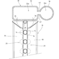
- the ice making unit 12 of the flow-down type ice making machine is disposed between a pair of ice making plates 14 and 14 that are vertically arranged and face each other, and both ice making plates 14 and 14.
- the cooling pipe 16 is basically configured to be provided in a meandering manner and to which a coolant is circulated and supplied.
- each ice making plate 14 On the ice making surface of each ice making plate 14, a plurality of ice making regions 20 in which ice is generated are defined in the width direction by a plurality of partition members 18 extending in the vertical direction.
- a water sprinkler 22 is provided above the ice making unit 12 to supply ice making water circulated from the circulation pump 54 to the ice making region 20.
- the water sprinkler 22 is a long cylindrical body having a substantially rectangular cross section, and is disposed so as to extend in the width direction along the upper side of the ice making unit 12.
- the sprinkler 22 has an introduction portion 24 connected to an ice-making water supply pipe 52 led out from the circulation pump 54 at one end portion in the width direction, and the other end portion is closed.
- a plurality of watering holes 26 are provided at the bottom of the water sprinkler 22 so as to be spaced apart from each other in the width direction corresponding to the ice making regions 20.
- the watering holes 26 are each set to a small diameter of about 3 mm to 5 mm so as not to be clogged by foreign matter contained in the ice making water.
- the circulation pump 54 is operated to pump the ice making water to the sprinkler 22, and the ice making water is sprayed to each ice making region 20 through each water sprinkling hole 26.
- the refrigerant is circulated and supplied from the condenser (not shown) to the cooling pipe 16, and the ice making water sprayed from the sprinkler 22 and flowing down on the ice making surface is cooled at a portion in contact with the cooling pipe 16 on the ice making surface. It is supposed to freeze.
- the deicing operation the supply of ice making water to the water sprinkler 22 is stopped, and the deicing water is supplied from the deicing water supply means 28 (see FIG.
- ice-making water pumped by the circulation pump 54 flows in vigorously from the introduction part 24 toward the closed end, and the flow rate of the ice-making water is high on the introduction part 24 side, and the pressure increases on the closed end side. Therefore, while the amount of ice making water sprayed from the water sprinkling hole 26 on the closed end side increases, there is a problem that the amount of ice making water sprinkled from the water sprinkling hole 26 on the introduction portion 24 side decreases. In some cases, air is sucked from the water sprinkling hole 26 on the introduction part 24 side, and ice making water may not be sprinkled from the water sprinkling hole 26.
- the amount of ice making water supplied from the sprinkler 22 to each ice making region 20 varies, not only a certain size of ice is generated in each ice making region 20, but also deformed ice and cloudy ice are generated. And the commercial value of ice will be greatly impaired.
- the ice making water sprayed from the water sprinkling hole 26 may flow obliquely from the introduction part 24 side toward the closed end side, get over the partition member 18 and scatter to the outside of the ice making part 12, resulting in insufficient ice making water. There is a risk of causing adverse effects such as melting ice stored below the ice making unit 12.
- An object of the present invention is to provide a sprinkler for an ice machine.
- the water sprayer of the ice making machine of the present invention comprises: In the water sprinkler of an ice making machine that receives the ice making water that is pumped and supplies it to the ice making area of the ice making unit, A water sprinkling portion that is provided over the ice making portion in the width direction of the ice making portion and supplies ice making water to the ice making region of the ice making portion from water sprinkling holes spaced apart in the width direction, A buffer part provided side by side in the watering part and having an introduction part at one end in the width direction for receiving the pumped ice-making water, It is provided between the said watering part and the said buffer part,
- the communication part which guides the ice-making water received in this buffer part to a watering part through a communication hole is characterized by the above-mentioned.
- ice making water can be evenly supplied to the ice making region of the ice making unit.
- FIG. 1 It is a front view which shows the ice making part of the flow-down type ice making machine which provided the water sprinkler which concerns on the suitable Example of this invention. It is a sectional side view which shows the ice making part of the flow-down type ice making machine which provided the water sprinkler of the Example.
- (a) is a top view which shows the watering device of an Example
- (b) is the sectional view on the AA line of (a).
- (a) is a top view which shows the watering device provided with the communication part of the modification 1
- (b) is sectional drawing cut
- (a) is a top view which shows the watering device provided with the communication part of the modification 2
- (b) is sectional drawing cut
- the ice making parts 12 of the flow-down type ice making machine provided with the water sprinkler according to the embodiment are arranged vertically so that the plate surfaces extend substantially vertically and face each other. It consists of a pair of ice-making plates 14 and 14. Between the opposing surfaces of the ice making plates 14 and 14, a cooling pipe 16 is provided which is repeatedly meandered so that the straight portion extends in the width direction of the ice making portion 12. It contacts the back side (opposing surface) of the ice making plates 14 and 14.
- Each ice making plate 14 is an ice making surface opposite to the surface facing the other ice making plate 14, and a plurality of partitioning members 18 are provided so as to protrude in the longitudinal direction of the ice making surface of each ice making plate 14.
- the plurality of partition members 18 are arranged to be separated from each other in the width direction of the ice making plate 14, and a plurality of ice making regions 20 are defined on the ice making surface along the width direction of the ice making plate 14 by these partition members 18.
- a water sprinkler 30 that supplies ice making water to the ice making region 20 of each ice making plate 14 during ice making operation and a deicing water supply that supplies deicing water to the back side of each ice making plate 14 during ice removing operation.
- Means 28 are provided.
- an ice making water tank 50 for storing ice making water flowing down the ice making plates 14, 14 is disposed below the ice making section 12.
- the ice making water tank 50 is connected to a circulation pump (pressure feeding means) via an ice making water supply pipe 52. ) 54.
- refrigerant is supplied to the cooling pipe 16 from the refrigeration system, and ice making water is supplied from the water sprinkler 30 to each ice making region 20, thereby generating substantially half-moon-shaped ice in the ice making region 20. It has become so.
- hot gas is supplied to the cooling pipe 16 by switching the refrigeration system valve, and deicing water is supplied from the deicing water supply means 28 to the back side of the ice making plates 14 and 14.
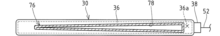
- the water sprinkler 30 includes a water sprinkling part 32 disposed above the ice making part 12, a buffer part 36 that receives ice-making water pumped by a circulation pump 54, a water sprinkling part 32, and a buffer part. And a communication portion 40 for connecting and communicating 36.
- the watering portion 32, the buffer portion 36, and the communication portion 40 are integrally formed from a synthetic resin material.
- the water sprinkling part 32 is a hollow cylindrical body having a circulation space 32a in which ice-making water circulates, and is formed in a substantially rectangular cross section in the embodiment.
- the water sprinkling unit 32 is disposed above the ice making unit 12.
- the water sprinkling portion 32 extends over the entire width direction of the ice making plate 14 and is approximately the size from the protruding end of the partition member 18 in one ice making plate 14 to the protruding end of the partition member 18 in the other ice making plate 14. It is formed with a matching size (see FIG. 2).
- a sprinkling hole group including a plurality of sprinkling holes 34 that are arranged in parallel and spaced apart from each other in the opposing direction of the pair of ice making plates 14, 14 at the bottom of the sprinkling portion 32 is provided in each ice making plate 14. Correspondingly, they are provided (see FIG. 3).
- each water sprinkling hole 34 constituting the sprinkling hole group is located on the ice making surface side of the ice making plate 14 and is arranged in the width direction of the ice making plate 14 so as to correspond to each ice making region 20 of the ice making plate 14.
- each ice making region 20 is disposed at the center in the width direction.
- the buffer portion 36 is a hollow cylindrical body having a buffer space 36a in which ice-making water circulates, and is formed in a circular cross section in the embodiment. Further, the buffer part 36 is provided side by side on the side of the water spray part 32. Here, the buffer part 36 is provided so as to extend in the width direction of the ice making part 12, and is formed in the same size as the size of the water sprinkling part 32 in the width direction in the embodiment. Furthermore, the buffer part 36 is provided with an introduction part 38 to which the ice making water supply pipe 52 is connected at one end in the width direction, and the other end in the width direction is closed.
- the communication part 40 includes a communication hole 42 communicating with the circulation space 32a of the water spraying part 32 and the buffer space 36a of the buffer part 36.
- the communication hole 42 is connected to the buffer space 36a of the buffer part 36 via the introduction part 38. It is configured to extend in a lateral direction that intersects the inflow direction of the ice making water supplied (see FIG. 2).
- the communicating part 40 of the embodiment is composed of a plurality of rectangular cylinders 41 that are spaced apart in the width direction of the ice making part, and one communicating hole 42 is opened in each rectangular cylinder 41 (see FIG. 3). ).
- the plurality of communication holes 42 are all formed with the same cross-sectional dimensions (see FIG. 3B).
- the plurality of communication holes 42 are provided so as to communicate with a position shifted in the width direction from the water spray holes 34 that are spaced apart in the width direction of the water sprinkling part 32 in the water sprinkling part 32 (see FIG. 3A).
- the communicating hole 42 of an Example is arrange
- the ice making water is passed through each communication hole 42 from the lateral direction intersecting the separating direction of the plurality of water sprinkling holes 34 constituting the water sprinkling hole group (the width direction of the ice making part 12). Is introduced. Then, the ice making water hits the inner wall of the water sprinkling part 32 facing the communication hole 42 in the circulation space 32a, and the flow velocity is further reduced, and the ice making water is guided along the inner wall to both sides in the width direction.
- the flow velocity difference and the pressure difference of the ice making water are reduced in the width direction, and the ice making water can be evenly discharged from the plurality of water sprinkling holes 34 provided in the water sprinkling part 32 in a balanced manner. .
- the water sprinkler 30 receives the pressure-fed ice making water by the buffer 36 and introduces it into the water sprinkling part 32 through the communication hole 42 of the communication part 40.
- the ice making unit 12 the ice grows stably and evenly in each ice making region 20, and the resulting ice also has a uniform size, and generation of deformed ice or cloudy ice due to excess or deficiency of the ice making water is generated. Can be suppressed.
- the ice making unit 12 can perform ice making evenly in the entire ice making region 20 in each ice making plate 14, so that the cooling efficiency and the deicing efficiency are good and the ice making capacity can be improved. Further, since the flow rate of ice making water is suppressed, the ice making water does not flow obliquely from each water sprinkling hole 34, and the ice making water shortage or the ice stored below the ice making part 12 due to splashing outside the ice making part 12 Inconveniences such as melting can be avoided.
- the water sprinkler 30 acts such that the plurality of communication holes 42 respectively reduce the flow speed of the ice making water.
- the water sprinkler 30 is provided so that each communication hole 42 communicates with the position shifted in the width direction from the water spray hole 34 in the water spray part 32, so that ice-making water flowing into the circulation space 32 a of the water spray part 32 from the communication hole 42 is provided.
- the ice making water buffered by the water sprinkling part 32 can be prevented from flowing out from the water sprinkling holes 34, and can be made to flow out from the water sprinkling holes 34.
- the present invention is not limited to the configuration of the embodiment, and can be modified as follows.
- the same components as those of the ice making unit 12 and the water sprinkler 30 of the embodiment are denoted by the same reference numerals and description thereof is omitted.
- the communication portion 40 is composed of a plurality of independent rectangular cylinders 41.
- the structure which forms the communicating hole 64 by making it swell so that it may space apart from the other plate-shaped part 63 may be sufficient. That is, the water sprinkler 30 can employ a configuration in which a plurality of communication holes 64 are provided in one communication portion 62 so as to be separated in the width direction. Each communication hole 64 has a circular cross-sectional shape, and the plurality of communication holes 64 are all formed in the same size (see FIG. 4B).
- the communication portion 67 is configured such that the size of the communication hole 68 decreases from one end side in the width direction where the introduction portion 38 of the buffer portion 36 is provided toward the other end side. Also good.
- the buffer portion 36 although the flow velocity difference between the ice making water is buffered to some extent by the buffer space 36a, there is a flow velocity difference between the introduction portion 14 side and the closed end side, and the communication hole 68 provided on the introduction portion 38 side. However, the ice making water does not easily flow into the communication hole 68 provided on the closed end side.
- the communication hole 68 on the introduction part 38 side of the buffer part 36 where ice making water is difficult to flow in is set large, and the communication hole 68 on the closed end side of the buffer part 36 where ice making water is easy to flow in is set to the introduction part 38.
- the communication portion 40 is composed of a plurality of independent rectangular cylinders 41.
- the communication portion 72 is formed so as to extend in the width direction of the ice making portion 12 like the water sprinkler 30 shown in FIG. You may comprise with a elongate single cylindrical body.
- the communication portion 72 is provided with one communication hole 74 whose length extends in the width direction of the ice making portion 12. As described above, if one communication hole 74 is provided in one communication portion 72, molding is easy.
- the plurality of communication holes 74 are formed to have the same vertical dimension in the width direction (see FIG. 6B). (4) As shown in FIG.
- the size of the communication hole 78 gradually narrows from the one end side in the width direction where the introduction portion 38 of the buffer portion 36 is provided to the other end side. It may be configured.
- the communication hole 82 is not the structure which becomes narrow gradually toward the other end side from the width direction one end side, but toward the other end side from the width direction one end side. In other words, the configuration may be narrowed in stages.
- the buffer portion 36 although the flow rate difference between the ice making water is buffered to some extent by the buffer space 36 a, there is a flow rate difference between the introduction portion 38 side and the closed end side, and the ice making water is connected to the communication holes 78 and 82 on the introduction portion 38 side.
- the communication holes 78 and 82 have a large vertical dimension on the side of the introduction part 38 of the buffer part 36 where ice making water is difficult to flow in.
- the ice making water flows into the circulation space 32a of the water sprinkling portion 32 from the communication holes 78 and 82 so as to be even in the width direction, and the amount of ice making water sprayed from the plurality of water sprinkling holes 34 is further equalized. .
- the buffer portion 36 of the embodiment is formed so that the buffer space 36a has the same cross-sectional dimension from one end side in the width direction to the other end side.
- the buffer portion according to another example shown in FIG. 90 the buffer space 90a can be gradually narrowed from one end in the width direction where the introduction portion 38 is provided toward the other end.
- the buffer space 92a is gradually reduced from one end side in the width direction where the introduction part 38 is provided toward the other end side. Also good.
- the ice making water flowing into the buffer spaces 90a and 92a from the introduction portion 38 hits not only the closed end but also the inner walls of the buffer portions 90 and 92 positioned in the traveling direction. , 92 improves the buffering action against ice making water.
- the present invention can be applied.
- a fountain having a cell-type ice making unit that generates ice by spraying and supplying ice making water to an ice making chamber provided in the ice making unit The present invention can also be applied to a type ice machine or a plate type ice machine that generates plate-like ice.
Abstract
Description
圧送される製氷水を受けて製氷部の製氷領域へ供給する製氷機の散水器において、
前記製氷部の上方に該製氷部の幅方向に亘って設けられ、該幅方向に離間配置した散水孔から該製氷部の製氷領域に製氷水を供給する散水部と、
前記散水部に並べて設けられ、圧送された製氷水を受け入れる導入部を前記幅方向の一端に有する緩衝部と、
前記散水部と前記緩衝部との間に設けられ、該緩衝部に受け入れた製氷水を連通孔を介して散水部に導く連通部とを備えたことを特徴とする。 In order to overcome the above-mentioned problems and achieve the intended purpose, the water sprayer of the ice making machine of the present invention comprises:
In the water sprinkler of an ice making machine that receives the ice making water that is pumped and supplies it to the ice making area of the ice making unit,
A water sprinkling portion that is provided over the ice making portion in the width direction of the ice making portion and supplies ice making water to the ice making region of the ice making portion from water sprinkling holes spaced apart in the width direction,
A buffer part provided side by side in the watering part and having an introduction part at one end in the width direction for receiving the pumped ice-making water,
It is provided between the said watering part and the said buffer part, The communication part which guides the ice-making water received in this buffer part to a watering part through a communication hole is characterized by the above-mentioned.
36,90,92 緩衝部,38 導入部,
40,62,67,72,76,80 連通部,
42,64,68,74,78,82 連通孔,
90a,92a 緩衝空間(内部空間) 12 ice making parts, 20 ice making areas, 32 sprinkling parts, 34 sprinkling holes,
36,90,92 buffer section, 38 introduction section,
40,62,67,72,76,80 communication part,
42,64,68,74,78,82 communication hole,
90a, 92a Buffer space (internal space)
次に、実施例に係る散水器30の作用について説明する。製氷運転において、散水器30には、製氷水タンク50から循環ポンプ54で圧送された製氷水が、製氷水供給管52を介して導入部38から緩衝部36の緩衝空間36aに供給される。緩衝部36は、製氷水の流入方向に位置する幅方向他端が閉塞しているので、製氷水は、緩衝部36の閉塞端に当たって流速を落とした後、各連通孔42を介して緩衝空間36aから散水部32の流通空間32aに導かれる。すなわち、散水部32の流通空間32aには、各散水孔群を構成する複数の散水孔34の離間方向(製氷部12の幅方向)と交差する横方向から各連通孔42を介して製氷水が導入される。そして、製氷水は、流通空間32aにおいて連通孔42に対向する散水部32の内壁に当たって流速が更に落とされて、当該内壁に沿って幅方向両側に案内される。従って、散水部32の流通空間32aでは、幅方向において製氷水の流速差および圧力差が小さくなり、散水部32に設けた複数の散水孔34からバランスよく製氷水を均等に流出させることができる。 (Effects of Example)
Next, the effect | action of the watering
本発明は、実施例の構成に限定されず、以下の如く変更することも可能である。図4~図9を参照して説明する変更例において、実施例の製氷部12および散水器30と同様の構成については同一の符号を付して説明を省略する。 (Change example)
The present invention is not limited to the configuration of the embodiment, and can be modified as follows. In the modified example described with reference to FIGS. 4 to 9, the same components as those of the
(2)図5に示すように、連通部67を、緩衝部36の導入部38が設けられる幅方向の一端側から他端側に向かうにつれて連通孔68の大きさが小さくなるよう構成してもよい。ここで、緩衝部36では、緩衝空間36aにより製氷水の流速差がある程度は緩衝されるものの、導入部14側と閉塞端側で流速差があって、導入部38側に設けた連通孔68に製氷水が流入し難い一方、閉塞端側に設けた連通孔68には製氷水が流入し易い。すなわち、製氷水が流入し難い緩衝部36の導入部38側の連通孔68を大きく設定し、これに対して製氷水が流入し易い緩衝部36の閉塞端側の連通孔68を、導入部38側のものより小さくなるように設定することで、複数の連通孔68に流入する製氷水の量のバランスをとることができる。従って、散水部32の流通空間32aに複数の連通孔68から幅方向に均等になるよう製氷水が流入し、複数の散水孔34から散水される製氷水の量も更なる均等化が図られる。 (1) In the embodiment, the
(2) As shown in FIG. 5, the
(4)図7に示すように、連通部76を、緩衝部36の導入部38が設けられる幅方向の一端側から他端側に向かうにつれて連通孔78の大きさが徐々に狭小になるよう構成してもよい。なお、図8に示す別例の連通部80の如く、連通孔82は、幅方向一端側から他端側に向けて徐々に狭小になる構成ではなく、幅方向一端側から他端側に向けて段階的に狭小になる構成であってもよい。緩衝部36では、緩衝空間36aにより製氷水の流速差がある程度は緩衝されるものの、導入部38側と閉塞端側で流速差があって、導入部38側では連通孔78,82に製氷水が流入し難い一方、閉塞端側では連通孔78,82に製氷水が流入し易い。すなわち、連通孔78,82は、製氷水が流入し難い緩衝部36の導入部38側の上下寸法を大きく設定し、これに対して製氷水が流入し易い緩衝部36の閉塞端側の上下寸法を導入部38側と比べて小さくなるように設定することで、連通孔78,82の全体に亘って流通する製氷水の量のバランスをとることができる。従って、散水部32の流通空間32aに連通孔78,82から幅方向に均等になるよう製氷水が流入し、複数の散水孔34から散水される製氷水の量も更なる均等化が図られる。 (3) In the embodiment, the
(4) As shown in FIG. 7, the size of the
(7)流下式製氷機の製氷部に本願発明を適用する例について説明したが、製氷部に設けられた製氷室に製氷水を噴射供給して氷を生成するセル型の製氷部を有する噴水式製氷機や、板状氷を生成するプレート式製氷機であっても、本願発明を適用できる。 (6) In the embodiment, the configuration in which the ice making water pumped by the pump as the pumping means is received by the buffer unit has been described. However, the ice making water pressurized by the pumping means outside the ice making machine from an external water source such as a tap water Even if it is supplied, the present invention can be applied.
(7) Although the example in which the present invention is applied to the ice making unit of the flow-down type ice making machine has been described, a fountain having a cell-type ice making unit that generates ice by spraying and supplying ice making water to an ice making chamber provided in the ice making unit The present invention can also be applied to a type ice machine or a plate type ice machine that generates plate-like ice.
Claims (5)
- 圧送される製氷水を受けて製氷部(12)の製氷領域(20)へ供給する製氷機の散水器において、
前記製氷部(12)の上方に該製氷部(12)の幅方向に亘って設けられ、該幅方向に離間配置した散水孔(34)から該製氷部(12)の製氷領域(20)に製氷水を供給する散水部(32)と、
前記散水部(32)に並べて設けられ、圧送された製氷水を受け入れる導入部(38)を前記幅方向の一端に有する緩衝部(36,90,92)と、
前記散水部(32)と前記緩衝部(36,90,92)との間に設けられ、該緩衝部(36,90,92)に受け入れた製氷水を連通孔(42,64,68,74,78,82)を介して散水部(32)に導く連通部(40,62,67,72,76,80)とを備えた
ことを特徴とする製氷機の散水器。 In the sprinkler of the ice making machine that receives the ice making water that is pumped and supplies it to the ice making area (20) of the ice making unit (12)
The ice making section (12) is provided across the width direction of the ice making section (12) above the ice making section (12), and from the sprinkling holes (34) spaced apart in the width direction to the ice making area (20) of the ice making section (12). A watering part (32) for supplying ice making water,
A buffer section (36, 90, 92) provided at one end in the width direction, which is provided side by side with the water sprinkling section (32) and has an introduction section (38) for receiving the pumped ice-making water,
Ice-making water provided between the water sprinkling part (32) and the buffer part (36, 90, 92) and received in the buffer part (36, 90, 92) communicates with the communication hole (42, 64, 68, 74). , 78, 82) and a communicating part (40, 62, 67, 72, 76, 80) leading to the watering part (32) through the water sprinkler of the ice making machine. - 前記連通部(40,62,67)は、前記幅方向に離間して前記連通孔(42,64,68)が複数設けられる請求項1記載の製氷機の散水器。 The water sprinkler of an ice making machine according to claim 1, wherein the communication part (40, 62, 67) is provided with a plurality of the communication holes (42, 64, 68) separated in the width direction.
- 前記連通部(72,76,80)は、前記幅方向に延在させて形成した連通孔(74,78,82)を備えている請求項1記載の製氷機の散水器。 The water sprinkler of an ice making machine according to claim 1, wherein the communication portion (72, 76, 80) includes a communication hole (74, 78, 82) formed to extend in the width direction.
- 前記連通部(67,76,82)は、前記緩衝部(36,90,92)の導入部(38)が設けられる一端側から他端側に向かうにつれて前記連通孔(68,78,82)の大きさが小さくなるよう構成される請求項2または3記載の製氷機の散水器。 The communication part (67, 76, 82) is connected to the communication hole (68, 78, 82) from the one end side where the introduction part (38) of the buffer part (36, 90, 92) is provided toward the other end side. The water sprinkler of the ice making machine according to claim 2 or 3, wherein the size of the ice making machine is reduced.
- 前記緩衝部(90,92)は、該緩衝部(90,92)の導入部(38)が設けられる一端側から他端側に向かうにつれて内部空間(90a,92a)が狭小になるよう形成される請求項1~4の何れか一項に記載の製氷機の散水器。 The buffer portion (90, 92) is formed so that the internal space (90a, 92a) becomes narrower from one end side where the introduction portion (38) of the buffer portion (90, 92) is provided toward the other end side. The water sprinkler of the ice making machine according to any one of claims 1 to 4.
Priority Applications (3)
| Application Number | Priority Date | Filing Date | Title |
|---|---|---|---|
| EP09804870.5A EP2314959B1 (en) | 2008-08-05 | 2009-07-21 | Water spray device for ice making machine |
| CN200980127428XA CN102099642B (en) | 2008-08-05 | 2009-07-21 | Water spray device for ice making machine |
| US13/002,962 US20110113814A1 (en) | 2008-08-05 | 2009-07-21 | Water Spray Device for Ice Making Machine |
Applications Claiming Priority (2)
| Application Number | Priority Date | Filing Date | Title |
|---|---|---|---|
| JP2008202058A JP5275719B2 (en) | 2008-08-05 | 2008-08-05 | Ice machine sprinkler |
| JP2008-202058 | 2008-08-05 |
Publications (1)
| Publication Number | Publication Date |
|---|---|
| WO2010016383A1 true WO2010016383A1 (en) | 2010-02-11 |
Family
ID=41663606
Family Applications (1)
| Application Number | Title | Priority Date | Filing Date |
|---|---|---|---|
| PCT/JP2009/063059 WO2010016383A1 (en) | 2008-08-05 | 2009-07-21 | Water spray device for ice making machine |
Country Status (5)
| Country | Link |
|---|---|
| US (1) | US20110113814A1 (en) |
| EP (1) | EP2314959B1 (en) |
| JP (1) | JP5275719B2 (en) |
| CN (1) | CN102099642B (en) |
| WO (1) | WO2010016383A1 (en) |
Families Citing this family (2)
| Publication number | Priority date | Publication date | Assignee | Title |
|---|---|---|---|---|
| WO2012077972A2 (en) * | 2010-12-08 | 2012-06-14 | Woongjin Coway Co., Ltd | Ice maker and ice making method using the same |
| KR101732165B1 (en) * | 2015-06-17 | 2017-05-02 | 동부대우전자 주식회사 | Refrigerator including ice tray and ice tray and manufacturing method for ice tray |
Citations (4)
| Publication number | Priority date | Publication date | Assignee | Title |
|---|---|---|---|---|
| JPS48114352U (en) * | 1972-04-03 | 1973-12-27 | ||
| JPS5755899U (en) * | 1980-09-18 | 1982-04-01 | ||
| US4425964A (en) * | 1980-06-06 | 1984-01-17 | King-Seeley Thermos Co. | Solar collector-type heat transfer apparatus |
| JPH07218066A (en) | 1994-01-27 | 1995-08-18 | Hoshizaki Electric Co Ltd | Sprinkler for icemaker |
Family Cites Families (13)
| Publication number | Priority date | Publication date | Assignee | Title |
|---|---|---|---|---|
| US2701452A (en) * | 1950-07-28 | 1955-02-08 | Flakice Corp | Tube ice-making apparatus |
| US2807150A (en) * | 1955-04-01 | 1957-09-24 | Merlin S Chapman | Temperature control for ice making machine defrosting gases |
| NL123182C (en) * | 1959-07-10 | |||
| US3615054A (en) * | 1965-09-24 | 1971-10-26 | Aerojet General Co | Injectors |
| US4458503A (en) * | 1980-05-16 | 1984-07-10 | King-Seeley Thermos Co. | Ice product and method and apparatus for making same |
| JPS6028051U (en) * | 1983-08-03 | 1985-02-25 | 三菱重工業株式会社 | liquid spray equipment |
| DE3834892C1 (en) * | 1988-10-13 | 1990-04-12 | Bayern-Chemie Gesellschaft Fuer Flugchemische Antriebe Mbh, 8261 Aschau, De | |
| US5520011A (en) * | 1994-03-23 | 1996-05-28 | Hoshizaki Denki Kabushiki Kaisha | Ice making unit structure of flow type ice making machine |
| US6173916B1 (en) * | 1994-12-15 | 2001-01-16 | Eco-Snow Systems, Inc. | CO2jet spray nozzles with multiple orifices |
| US6394369B2 (en) * | 1999-12-22 | 2002-05-28 | Visteon Global Tech., Inc. | Nozzle |
| CN2784837Y (en) * | 2005-04-02 | 2006-05-31 | 青岛市家用电器研究所 | Water sprayer mounting structure of flow water type ice maker |
| CN200975816Y (en) * | 2006-11-21 | 2007-11-14 | 优可企业股份有限公司 | Ice making structure of water spraying type ice making machine |
| CN201034401Y (en) * | 2007-05-16 | 2008-03-12 | 宁波德贝里克电器有限公司 | Spraying arrangement for ice-making machine |
-
2008
- 2008-08-05 JP JP2008202058A patent/JP5275719B2/en not_active Expired - Fee Related
-
2009
- 2009-07-21 US US13/002,962 patent/US20110113814A1/en not_active Abandoned
- 2009-07-21 WO PCT/JP2009/063059 patent/WO2010016383A1/en active Application Filing
- 2009-07-21 EP EP09804870.5A patent/EP2314959B1/en active Active
- 2009-07-21 CN CN200980127428XA patent/CN102099642B/en active Active
Patent Citations (4)
| Publication number | Priority date | Publication date | Assignee | Title |
|---|---|---|---|---|
| JPS48114352U (en) * | 1972-04-03 | 1973-12-27 | ||
| US4425964A (en) * | 1980-06-06 | 1984-01-17 | King-Seeley Thermos Co. | Solar collector-type heat transfer apparatus |
| JPS5755899U (en) * | 1980-09-18 | 1982-04-01 | ||
| JPH07218066A (en) | 1994-01-27 | 1995-08-18 | Hoshizaki Electric Co Ltd | Sprinkler for icemaker |
Non-Patent Citations (1)
| Title |
|---|
| See also references of EP2314959A4 * |
Also Published As
| Publication number | Publication date |
|---|---|
| JP5275719B2 (en) | 2013-08-28 |
| CN102099642B (en) | 2012-08-15 |
| EP2314959B1 (en) | 2016-09-28 |
| JP2010038451A (en) | 2010-02-18 |
| EP2314959A1 (en) | 2011-04-27 |
| US20110113814A1 (en) | 2011-05-19 |
| EP2314959A4 (en) | 2013-12-25 |
| CN102099642A (en) | 2011-06-15 |
Similar Documents
| Publication | Publication Date | Title |
|---|---|---|
| US8375738B2 (en) | Sprinkle guide of water trickle ice-making machine | |
| US7444828B2 (en) | Ice discharging structure of ice making mechanism | |
| JP4994198B2 (en) | Flowing ice machine | |
| JP5052277B2 (en) | Ice making water tank of automatic ice machine | |
| WO2010016383A1 (en) | Water spray device for ice making machine | |
| TW200617333A (en) | Refrigerator | |
| CN212227450U (en) | Bullet ice type ice maker | |
| US20110120169A1 (en) | Water Sprinkle Pipe for Downflow Type Ice Making Machine | |
| JP2005090814A (en) | Injection type ice-making machine | |
| JP2002162137A (en) | Automatic ice machine | |
| KR200448110Y1 (en) | Ice maker able to maintain water flow quantity uniformly | |
| KR20140062847A (en) | Evaporator unit for water purifier integral vertical ellipse type | |
| JP2010190525A (en) | Ice-making water sprinkler of flow-down type ice making machine | |
| KR200480661Y1 (en) | Powder ice manufacture apparatus of rotating drum type | |
| CN102032743B (en) | Refrigerator | |
| CN217178995U (en) | A kind of refrigerator | |
| JPH0356870Y2 (en) | ||
| CN211120166U (en) | Evaporator assembly of running water type ice maker | |
| JP2011231943A (en) | Ice-making unit of flow-down type ice-making machine | |
| JP2007040637A (en) | Ice making water supply means for falling type ice making machine | |
| JPH0537177Y2 (en) | ||
| KR20180010794A (en) | Ice maker | |
| JP4307024B2 (en) | Ice machine | |
| JPS6243256Y2 (en) | ||
| KR101669605B1 (en) | water injection nozzles of rotating type for ice machine and ice machine using the same |
Legal Events
| Date | Code | Title | Description |
|---|---|---|---|
| WWE | Wipo information: entry into national phase |
Ref document number: 200980127428.X Country of ref document: CN |
|
| 121 | Ep: the epo has been informed by wipo that ep was designated in this application |
Ref document number: 09804870 Country of ref document: EP Kind code of ref document: A1 |
|
| REEP | Request for entry into the european phase |
Ref document number: 2009804870 Country of ref document: EP |
|
| WWE | Wipo information: entry into national phase |
Ref document number: 2009804870 Country of ref document: EP |
|
| WWE | Wipo information: entry into national phase |
Ref document number: 13002962 Country of ref document: US |
|
| NENP | Non-entry into the national phase |
Ref country code: DE |