WO2010014057A1 - Display characterization with filtration - Google Patents
Display characterization with filtration Download PDFInfo
- Publication number
- WO2010014057A1 WO2010014057A1 PCT/US2008/009147 US2008009147W WO2010014057A1 WO 2010014057 A1 WO2010014057 A1 WO 2010014057A1 US 2008009147 W US2008009147 W US 2008009147W WO 2010014057 A1 WO2010014057 A1 WO 2010014057A1
- Authority
- WO
- WIPO (PCT)
- Prior art keywords
- filter
- display
- screen
- color correction
- daylight
- Prior art date
Links
Classifications
-
- H—ELECTRICITY
- H04—ELECTRIC COMMUNICATION TECHNIQUE
- H04N—PICTORIAL COMMUNICATION, e.g. TELEVISION
- H04N17/00—Diagnosis, testing or measuring for television systems or their details
- H04N17/04—Diagnosis, testing or measuring for television systems or their details for receivers
-
- H—ELECTRICITY
- H04—ELECTRIC COMMUNICATION TECHNIQUE
- H04N—PICTORIAL COMMUNICATION, e.g. TELEVISION
- H04N9/00—Details of colour television systems
- H04N9/64—Circuits for processing colour signals
-
- H—ELECTRICITY
- H04—ELECTRIC COMMUNICATION TECHNIQUE
- H04N—PICTORIAL COMMUNICATION, e.g. TELEVISION
- H04N17/00—Diagnosis, testing or measuring for television systems or their details
- H04N17/02—Diagnosis, testing or measuring for television systems or their details for colour television signals
-
- H—ELECTRICITY
- H04—ELECTRIC COMMUNICATION TECHNIQUE
- H04N—PICTORIAL COMMUNICATION, e.g. TELEVISION
- H04N9/00—Details of colour television systems
- H04N9/64—Circuits for processing colour signals
- H04N9/73—Colour balance circuits, e.g. white balance circuits or colour temperature control
Definitions
- This invention relates to a display and a method of characterizing a display wherein the display includes a characterization system adapted to work with a measurement sensor that measures a difference between display characteristics and target values of a screen, wherein the screen is provided with at least a first filter, which is a color correction filter that decreases the difference between the display characteristics and the target values of the screen.
- Displays such as flat-panel displays, need to be calibrated or characterized so that the colors in an image reproduced by the display are an accurate representation of the colors originally intended to be displayed in the image.
- the colors originally intended to be displayed in the image by a creator of the image is typically referred to as a target look, which can be compared to a reference look.
- the reference look can be a universal standard or can be referenced against a universal or recognized standard on a standard reference display, which can be a CRT, for example.
- the director or creator can use the standard display in post-production to determine and/or assist the director or creator in obtaining the look of the images that are or are consistent with the intent for the director or creator.
- a goal of the display industry is to calibrate the target display to have the same performance as the standard reference display, so that the look of any video content can be matched to the standard reference display.
- each display needs to be calibrated or characterized so that the image that viewers see on the display looks the same or similar to the image originally intended and created for commercial and/or profession displays. Further, this means that the target displays must be capable of obtaining the reference look.
- There are many known calibration systems for calibrating or characterizing a display so that the images generated by the display are similar or identical to the reference look. The calibration system generally measures the characteristics of the display and calibrates the display to produce target values such as primary color gamut, gamma, color temperature, etc. consistent with the reference look.
- the performance of the calibration often depends on the original characteristics of the display. If the display shows too much deviation from target primary such as Rec. 709, which is a broadcasting standard, or color temperature (e.g., 6500K), then the calibration or characterization results are often not satisfactory. For example, if a correlated color temperature (CCT) of white on the display is 12,00OK and the target value is daylight 6,50OK, the deviation is so large that the characterization can not be properly performed. It is therefore necessary to provide an external device or method that compensates for the deviation between the display characteristics and the target value in order to ensure optimal characterization of the display and that the display is adapted to be calibrated.
- CCT correlated color temperature
- Figure 1 is an exploded view of a display according to an embodiment of the invention.
- Figure 2 is a plan view of the display of Figure 1 shown with a first filter and a second filter.
- the color correction filters can be color correction orange (CTO) that convert daylight to tungsten light and/or color correction blue (CTB) that convert tungsten light to daylight.
- CTO color correction orange
- CTB color correction blue
- the first filter 5 and the second filter 6 are CTO and convert daylight to tungsten light.
- the first filter 5 is 1/4 CTO
- the second filter 6 is 1/8 CTO.
- the combination of the first filter 5 and the second filter 6 is therefore 3/8 CTO.
- the characteristics of the first filter 5 are illustrated in more detail in Figure 3, and the characteristics of the second filter 6 are illustrated in more detail in Figure 4.
- the screen 2 is illustrated and described as having the first filter 5 and the second filter 6 with the characteristics described above, it will be appreciated by those skilled in the art that the number, type, and strength of the filters provided on the screen 2 can be varied depending on the desired characteristics of the display 1.
- the number, type, and strength of the filters can be determined by initially measuring the transmission of the display 1 that is to be characterized by any known method. If the display 1 shows more transmission in a blue spectral region (e.g., if a measured value of the white on the display 1 is about 12,00OK and a target value for the white is about 6,500K), at least one CTO type filter can be used to filter out excessive blue transmission.
- the display 1 shows more transmission in a yellowish-red spectral region (e.g., if the measured value of the white on the display 1 is about 3,00OK and the target value for the white is about 6,500K), at least one CBT type filter can be used to filter out excessive yellowish-red transmission. Depending on the difference between the measured value and the target value, the most appropriate number and strength of the filters can be chosen.
- the display 1 is connected to a characterization system 7.
- the characterization system 7 includes a personal computer (PC) 8 and a measurement sensor 9.
- the measurement sensor 9 is connected to the PC 8 via a standard communication channel, for example, a universal serial bus (USB) or RS-232C.
- characterization model which maps device dependent values (e.g., RGB) to device independent values (e.g., CIEXYZ).
- the characterization model is then used to generate a mapping, such as a three dimensional look-up-table, which produces a reference look on the screen 2. Because the characterization system 7 is known in the art, further description thereof has been omitted. Although the display 1 is illustrated and described as having the characterization system 7 illustrated and described herein, it will be appreciated by those skilled in the art that any known characterization systems can be used with the display 1.
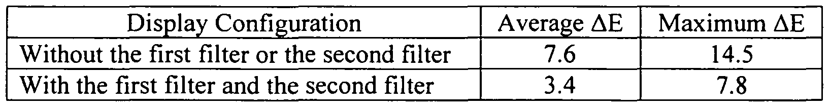
- Table 2 shows a comparison of the luminance Y, chromaticity x, chromaticity y, and white point CCT when the first filter 5 and the second filter 6 are not attached to the screen 2, and when the first filter 5 and the second filter 6 are attached to the screen 2.
- the invention includes the display having a means of enabling the display to be calibrated, recalibrated or measured by a characterization system having a measurement sensor that measures a difference between display characteristics and target values of a screen, wherein at least one target value can be an industry standard value.
- the screen is provided with at least a first filter, wherein the first filter can be a color correction filter that decreases the difference between the display characteristics and the target values of the screen.
- the first filter can set the display to operate such that it can match or achieve a reference look, and as such, the display can match or achieve the target look as intended by a director or creator.
- the first filter can be a color correction orange that converts daylight to tungsten light or color correction blue that converts tungsten light to daylight and the first filter can be complemented with a second filter, which can, for example, be a color correction orange that converts daylight to tungsten light or color correction blue that converts tungsten light to daylight.
- the enabling means can include the series of patches stored in memory of the display and can also having a measurement sensor input such as a USB port or the like for correlating measured display outputs to at least one the patches.
- the display can have a look-up table that contains the series of patches and the look-up table can be adapted to dynamically associate a given patch to the target values.
- first filter and/or the second filter being detachable such that the display can be recalibrated in case of an improper earlier calibration or a drift in the display over time.
- the screen can also be divided into different sections so that different patches of the plurality of patches can be assigned to the different sections of the screen in case the screen in not uniform.
- the first filter and/or second filter if there is one, can be divided to have different color characteristics associated with different sections of the screen.
Landscapes
- Engineering & Computer Science (AREA)
- Multimedia (AREA)
- Signal Processing (AREA)
- Health & Medical Sciences (AREA)
- Biomedical Technology (AREA)
- General Health & Medical Sciences (AREA)
- Controls And Circuits For Display Device (AREA)
- Spectrometry And Color Measurement (AREA)
- Testing, Inspecting, Measuring Of Stereoscopic Televisions And Televisions (AREA)
- Devices For Indicating Variable Information By Combining Individual Elements (AREA)
Abstract
Description

Claims
Priority Applications (6)
| Application Number | Priority Date | Filing Date | Title |
|---|---|---|---|
| US12/737,571 US20110122161A1 (en) | 2008-07-29 | 2008-07-29 | Display characterization with filtration |
| EP08794837.8A EP2314074A4 (en) | 2008-07-29 | 2008-07-29 | Display characterization with filtration |
| CN2008801305851A CN102113331A (en) | 2008-07-29 | 2008-07-29 | Display characterization with filtration |
| PCT/US2008/009147 WO2010014057A1 (en) | 2008-07-29 | 2008-07-29 | Display characterization with filtration |
| JP2011521066A JP2011529581A (en) | 2008-07-29 | 2008-07-29 | Display characterization by filtering |
| KR1020117001536A KR20110048508A (en) | 2008-07-29 | 2008-07-29 | Display Characterization Using Filters |
Applications Claiming Priority (1)
| Application Number | Priority Date | Filing Date | Title |
|---|---|---|---|
| PCT/US2008/009147 WO2010014057A1 (en) | 2008-07-29 | 2008-07-29 | Display characterization with filtration |
Publications (1)
| Publication Number | Publication Date |
|---|---|
| WO2010014057A1 true WO2010014057A1 (en) | 2010-02-04 |
Family
ID=41610595
Family Applications (1)
| Application Number | Title | Priority Date | Filing Date |
|---|---|---|---|
| PCT/US2008/009147 WO2010014057A1 (en) | 2008-07-29 | 2008-07-29 | Display characterization with filtration |
Country Status (6)
| Country | Link |
|---|---|
| US (1) | US20110122161A1 (en) |
| EP (1) | EP2314074A4 (en) |
| JP (1) | JP2011529581A (en) |
| KR (1) | KR20110048508A (en) |
| CN (1) | CN102113331A (en) |
| WO (1) | WO2010014057A1 (en) |
Cited By (1)
| Publication number | Priority date | Publication date | Assignee | Title |
|---|---|---|---|---|
| EP2536162A3 (en) * | 2011-06-16 | 2016-04-27 | Samsung Electronics Co., Ltd. | Display Apparatus and Calibration Method Thereof |
Families Citing this family (3)
| Publication number | Priority date | Publication date | Assignee | Title |
|---|---|---|---|---|
| JP5195250B2 (en) * | 2008-10-03 | 2013-05-08 | ソニー株式会社 | Image display system and image display apparatus |
| JP5932258B2 (en) * | 2011-07-15 | 2016-06-08 | キヤノン株式会社 | Display device and control method thereof |
| US10123005B2 (en) * | 2015-03-06 | 2018-11-06 | Apple Inc. | Displays with unit-specific display identification data |
Citations (4)
| Publication number | Priority date | Publication date | Assignee | Title |
|---|---|---|---|---|
| US20030169346A1 (en) * | 2002-01-30 | 2003-09-11 | Noriaki Ojima | Photographing apparatus and photographing method |
| US6788812B1 (en) * | 1999-06-18 | 2004-09-07 | Eastman Kodak Company | Techniques for selective enhancement of a digital image |
| US20070085816A1 (en) * | 1998-05-29 | 2007-04-19 | Silicon Graphics, Inc. | System and Method for Providing a Wide Aspect Ratio Flat Panel Display Monitor Independent White-Balance Adjustment and Gamma Correction Capabilities |
| US20070115647A1 (en) * | 2004-04-07 | 2007-05-24 | Gekko Technology Limited | Lighting apparatus |
Family Cites Families (76)
| Publication number | Priority date | Publication date | Assignee | Title |
|---|---|---|---|---|
| US4706108A (en) * | 1985-04-12 | 1987-11-10 | Sony Corporation | Automatic setup system for controlling color gain, hue and white balance of TV monitor |
| US5032007A (en) * | 1988-04-07 | 1991-07-16 | Honeywell, Inc. | Apparatus and method for an electronically controlled color filter for use in information display applications |
| US5173839A (en) * | 1990-12-10 | 1992-12-22 | Grumman Aerospace Corporation | Heat-dissipating method and device for led display |
| US5751261A (en) * | 1990-12-31 | 1998-05-12 | Kopin Corporation | Control system for display panels |
| US5347378A (en) * | 1991-04-04 | 1994-09-13 | Displaytech, Inc. | Fast switching color filters for frame-sequential video using ferroelectric liquid crystal color-selective filters |
| JPH0527729A (en) * | 1991-07-19 | 1993-02-05 | Sony Corp | Characteristic measuring instrument for display device |
| JPH05297369A (en) * | 1992-04-21 | 1993-11-12 | Sony Corp | Liquid crystal monitor |
| JP3234740B2 (en) * | 1994-06-09 | 2001-12-04 | キヤノン株式会社 | Image display device |
| US5689321A (en) * | 1995-04-13 | 1997-11-18 | Canon Kabushiki Kaisha | Display apparatus |
| US5805342A (en) * | 1995-10-31 | 1998-09-08 | Gravely; Benjamin T. | Imaging system with means for sensing a filtered fluorescent emission |
| KR100242834B1 (en) * | 1996-12-04 | 2000-02-01 | 윤종용 | An apparatus for emitting heat of lcd monitor |
| JPH10304184A (en) * | 1997-05-02 | 1998-11-13 | Fuji Xerox Co Ltd | Image processor and image processing method |
| US5892612A (en) * | 1997-08-07 | 1999-04-06 | Cambridge Research & Instrumentation Inc. | Tunable optical filter with white state |
| JP3247643B2 (en) * | 1997-09-10 | 2002-01-21 | インターナショナル・ビジネス・マシーンズ・コーポレーション | Liquid crystal display device |
| TW445386B (en) * | 1998-03-16 | 2001-07-11 | Hitachi Ltd | Thin-type display |
| US6078371A (en) * | 1998-10-05 | 2000-06-20 | Canon Kabushiki Kaisha | Liquid crystal device and liquid crystal display apparatus |
| JP2000232663A (en) * | 1999-02-10 | 2000-08-22 | Sony Corp | Device and method for color adjustment |
| JP3766231B2 (en) * | 1999-05-10 | 2006-04-12 | Necビューテクノロジー株式会社 | Liquid crystal display |
| US6483719B1 (en) * | 2000-03-21 | 2002-11-19 | Spraylat Corporation | Conforming shielded form for electronic component assemblies |
| JP2002023259A (en) * | 2000-07-07 | 2002-01-23 | Canon Inc | Projection-type image display device |
| TW554625B (en) * | 2000-12-08 | 2003-09-21 | Silicon Graphics Inc | Compact flat panel color calibration system |
| EP1398652A3 (en) * | 2001-04-27 | 2004-06-23 | Asahi Glass Co., Ltd. | Filter for plasma display panel |
| JP2003016950A (en) * | 2001-04-27 | 2003-01-17 | Asahi Glass Co Ltd | Filter for plasma display panel |
| TWI319526B (en) * | 2001-07-10 | 2010-01-11 | Fujitsu Ltd | Plane unit structure, portable computer and display unit (2) |
| JP2003076286A (en) * | 2001-09-06 | 2003-03-14 | Ngk Insulators Ltd | Cooling system for display device |
| US7390597B2 (en) * | 2002-06-13 | 2008-06-24 | Dai Nippon Printing Co., Ltd. | Method for manufacturing color filter |
| DE60334801D1 (en) * | 2002-08-02 | 2010-12-16 | Sony Corp | FLAT SCREEN DISPLAY DEVICE |
| KR100445033B1 (en) * | 2002-08-26 | 2004-08-18 | 삼성에스디아이 주식회사 | A case for covering electronic parts and a displaying apparatus having it |
| JP4168715B2 (en) * | 2002-09-19 | 2008-10-22 | 松下電器産業株式会社 | Display device |
| JP2004146211A (en) * | 2002-10-24 | 2004-05-20 | Noritake Co Ltd | Tabular display device and its sealing method |
| KR100522695B1 (en) * | 2003-09-01 | 2005-10-19 | 삼성에스디아이 주식회사 | Display apparatus |
| JP2005141194A (en) * | 2003-10-14 | 2005-06-02 | Seiko Epson Corp | Reinforcement structure, display device, and electronic equipment |
| US7457120B2 (en) * | 2004-04-29 | 2008-11-25 | Samsung Sdi Co., Ltd. | Plasma display apparatus |
| KR100553211B1 (en) * | 2004-05-24 | 2006-02-22 | 삼성에스디아이 주식회사 | Plasma display device |
| KR20050122517A (en) * | 2004-06-24 | 2005-12-29 | 삼성에스디아이 주식회사 | Plasma display panel assembly |
| DE602004024895D1 (en) * | 2004-10-25 | 2010-02-11 | Barco Nv | Optical correction for light panels with high uniformity |
| KR100669754B1 (en) * | 2004-11-10 | 2007-01-16 | 삼성에스디아이 주식회사 | Structure for heat dissipation of display panel, and display module equipped with the same |
| US7299996B2 (en) * | 2004-11-12 | 2007-11-27 | American Standard International Inc. | Thermostat with energy saving backlit switch actuators and visual display |
| KR100598406B1 (en) * | 2004-11-17 | 2006-07-07 | 삼성전자주식회사 | Display apparatus |
| KR100719540B1 (en) * | 2004-11-18 | 2007-05-17 | 삼성에스디아이 주식회사 | Supporting apparatus for Flat display panel and Flat panel display device with the same |
| JP2006152921A (en) * | 2004-11-29 | 2006-06-15 | Sony Corp | Cooling blower fan and video display unit |
| KR100683732B1 (en) * | 2004-12-10 | 2007-02-15 | 삼성에스디아이 주식회사 | Plasma display module |
| KR100649598B1 (en) * | 2004-12-29 | 2006-11-27 | 엘지전자 주식회사 | Cooling System of Plasma Display Panel Television |
| KR100730124B1 (en) * | 2004-12-30 | 2007-06-19 | 삼성에스디아이 주식회사 | Plasma display panel |
| EP1847767A4 (en) * | 2005-02-08 | 2013-01-23 | Fujifilm Corp | Light guide plate, and planar lighting device and liquid crystal display device using such light guide plate |
| KR20070114139A (en) * | 2005-02-16 | 2007-11-29 | 미쓰비시 가가꾸 폴리에스테르 필름 가부시키가이샤 | Near infrared ray absorbing filter, optical filter for plasma display and plasma display panel |
| CN1942914A (en) * | 2005-02-28 | 2007-04-04 | 松下电器产业株式会社 | Flat panel display device |
| JP4736481B2 (en) * | 2005-03-14 | 2011-07-27 | ソニー株式会社 | Semiconductor device |
| WO2006098365A1 (en) * | 2005-03-15 | 2006-09-21 | Matsushita Electric Industrial Co., Ltd. | Display device |
| JPWO2006098140A1 (en) * | 2005-03-16 | 2008-08-21 | 松下電器産業株式会社 | Liquid crystal display device and portable terminal device |
| US20060221218A1 (en) * | 2005-04-05 | 2006-10-05 | Doron Adler | Image sensor with improved color filter |
| KR100708682B1 (en) * | 2005-04-13 | 2007-04-17 | 삼성에스디아이 주식회사 | Plasma display module |
| US20060279494A1 (en) * | 2005-06-13 | 2006-12-14 | I-Hwei Yen | Color compensation system and color compensation method for a display |
| KR100730138B1 (en) * | 2005-06-28 | 2007-06-19 | 삼성에스디아이 주식회사 | Plasma display apparatus |
| KR100772247B1 (en) * | 2005-11-04 | 2007-11-01 | 엘지전자 주식회사 | Flat display device cooling apparatus for use in the same |
| US7463487B2 (en) * | 2005-11-04 | 2008-12-09 | Lg Electronics Inc. | Cooling apparatus for flat display device |
| KR100731366B1 (en) * | 2005-11-04 | 2007-06-21 | 엘지전자 주식회사 | Cooling apparatus for flat display device and cross flow fan for the same |
| JP2007155808A (en) * | 2005-11-30 | 2007-06-21 | Orion Denki Kk | Display device with heat radiation structure and plasma display device with heat radiation structure |
| JP2007187996A (en) * | 2006-01-16 | 2007-07-26 | Photo Craft Co Ltd | Image display method and apparatus |
| JP2007212712A (en) * | 2006-02-09 | 2007-08-23 | Epson Imaging Devices Corp | Electrooptical device and electronic apparatus |
| GB0611126D0 (en) * | 2006-06-06 | 2006-07-19 | Liquavista Bv | Colour display device |
| JP2006309265A (en) * | 2006-07-11 | 2006-11-09 | Hitachi Plasma Patent Licensing Co Ltd | Flat display device |
| TWI332191B (en) * | 2006-09-28 | 2010-10-21 | Wistron Corp | Method and apparatus of looking for new color temperature point |
| TWI302590B (en) * | 2006-10-04 | 2008-11-01 | Sunonwealth Electr Mach Ind Co | Heat-dissipating module for a back light set of a liquid crystal display |
| JP4851908B2 (en) * | 2006-10-10 | 2012-01-11 | 株式会社 日立ディスプレイズ | Liquid crystal display |
| JP5403860B2 (en) * | 2006-10-10 | 2014-01-29 | 株式会社ジャパンディスプレイ | Color liquid crystal display device |
| KR101315465B1 (en) * | 2006-10-16 | 2013-10-04 | 삼성전자주식회사 | Cooling fan unit and display apparatus having the same |
| JP5258277B2 (en) * | 2006-12-26 | 2013-08-07 | 株式会社半導体エネルギー研究所 | Liquid crystal display |
| KR101273592B1 (en) * | 2007-01-08 | 2013-06-11 | 삼성전자주식회사 | Panel type display device |
| US8148729B2 (en) * | 2007-04-27 | 2012-04-03 | Lg Display Co., Ltd. | Organic light emitting device |
| US8421718B2 (en) * | 2007-05-21 | 2013-04-16 | Lg Display Co., Ltd. | Organic light emitting device |
| WO2009025025A1 (en) * | 2007-08-20 | 2009-02-26 | Mitsubishi Electric Corporation | Display device |
| US20090096716A1 (en) * | 2007-09-12 | 2009-04-16 | Lg Electronics Inc. | Display device |
| KR101323394B1 (en) * | 2007-09-12 | 2013-10-29 | 엘지디스플레이 주식회사 | Organic Light Emitting Display |
| KR101383454B1 (en) * | 2007-09-21 | 2014-04-08 | 엘지디스플레이 주식회사 | Light emitting device |
| US20090162667A1 (en) * | 2007-12-20 | 2009-06-25 | Lumination Llc | Lighting device having backlighting, illumination and display applications |
-
2008
- 2008-07-29 KR KR1020117001536A patent/KR20110048508A/en not_active Application Discontinuation
- 2008-07-29 CN CN2008801305851A patent/CN102113331A/en active Pending
- 2008-07-29 US US12/737,571 patent/US20110122161A1/en not_active Abandoned
- 2008-07-29 EP EP08794837.8A patent/EP2314074A4/en not_active Withdrawn
- 2008-07-29 JP JP2011521066A patent/JP2011529581A/en active Pending
- 2008-07-29 WO PCT/US2008/009147 patent/WO2010014057A1/en active Application Filing
Patent Citations (4)
| Publication number | Priority date | Publication date | Assignee | Title |
|---|---|---|---|---|
| US20070085816A1 (en) * | 1998-05-29 | 2007-04-19 | Silicon Graphics, Inc. | System and Method for Providing a Wide Aspect Ratio Flat Panel Display Monitor Independent White-Balance Adjustment and Gamma Correction Capabilities |
| US6788812B1 (en) * | 1999-06-18 | 2004-09-07 | Eastman Kodak Company | Techniques for selective enhancement of a digital image |
| US20030169346A1 (en) * | 2002-01-30 | 2003-09-11 | Noriaki Ojima | Photographing apparatus and photographing method |
| US20070115647A1 (en) * | 2004-04-07 | 2007-05-24 | Gekko Technology Limited | Lighting apparatus |
Non-Patent Citations (1)
| Title |
|---|
| See also references of EP2314074A4 * |
Cited By (2)
| Publication number | Priority date | Publication date | Assignee | Title |
|---|---|---|---|---|
| EP2536162A3 (en) * | 2011-06-16 | 2016-04-27 | Samsung Electronics Co., Ltd. | Display Apparatus and Calibration Method Thereof |
| KR101831400B1 (en) | 2011-06-16 | 2018-02-26 | 삼성전자주식회사 | Display apparatus and calibration method thereof |
Also Published As
| Publication number | Publication date |
|---|---|
| KR20110048508A (en) | 2011-05-11 |
| US20110122161A1 (en) | 2011-05-26 |
| EP2314074A4 (en) | 2013-06-26 |
| EP2314074A1 (en) | 2011-04-27 |
| CN102113331A (en) | 2011-06-29 |
| JP2011529581A (en) | 2011-12-08 |
Similar Documents
| Publication | Publication Date | Title |
|---|---|---|
| US8654142B2 (en) | Accurate color display device | |
| US7965300B2 (en) | Methods and systems for efficient white balance and gamma control | |
| US6844881B1 (en) | Method and apparatus for improved color correction | |
| KR100787215B1 (en) | Display characteristic calibration method, display characteristic calibration device, and computer program | |
| US5561459A (en) | Automatic profile generation for a self-calibrating color display | |
| JP5354265B2 (en) | Liquid crystal display | |
| EP1478192B1 (en) | Image processing system, projector, information storage medium, and image processing method | |
| US8411936B2 (en) | Apparatus and method for color reproduction | |
| JP5938844B2 (en) | Display device | |
| US20090167782A1 (en) | Correction of color differences in multi-screen displays | |
| JP2004228948A (en) | Image processing system, projector, program, information storage medium and image processing method | |
| US20110148907A1 (en) | Method and system for image display with uniformity compensation | |
| CN110570811A (en) | LED color gamut correction method | |
| EP2314074A1 (en) | Display characterization with filtration | |
| JP5447058B2 (en) | Gradation correction apparatus, display and gradation correction method | |
| TWI415104B (en) | Method and system for calibrating colour purity of display panel and display apparatus having such calibrated display panel | |
| US20100309218A1 (en) | Method for color calibration and device using the same | |
| KR20040077353A (en) | A method of revision colour temperature with inverse gamma for liquid crystal display | |
| JP2012217052A (en) | Color display method and color display device | |
| JP2003179946A (en) | Chromaticity correcting equipment | |
| CN117746808A (en) | Display calibration method, display panel calibration system and display device | |
| TWM586021U (en) | Ubiquitous auto calibration device | |
| Stojmenovik | Technology for Grade 1 LCDs | |
| Ha et al. | Correction of the Hue Shift Phenomenon Due to an Additional White Channel in a DLP Projector | |
| Song et al. | Gray Scale CCT Compensation of Mobile Phone LCD. |
Legal Events
| Date | Code | Title | Description |
|---|---|---|---|
| WWE | Wipo information: entry into national phase |
Ref document number: 200880130585.1 Country of ref document: CN |
|
| 121 | Ep: the epo has been informed by wipo that ep was designated in this application |
Ref document number: 08794837 Country of ref document: EP Kind code of ref document: A1 |
|
| ENP | Entry into the national phase |
Ref document number: 20117001536 Country of ref document: KR Kind code of ref document: A |
|
| ENP | Entry into the national phase |
Ref document number: 2011521066 Country of ref document: JP Kind code of ref document: A |
|
| WWE | Wipo information: entry into national phase |
Ref document number: 12737571 Country of ref document: US |
|
| NENP | Non-entry into the national phase |
Ref country code: DE |
|
| WWE | Wipo information: entry into national phase |
Ref document number: 2008794837 Country of ref document: EP |