WO2010013520A1 - Indenopyrene compound, organic thin film solar cell material using the same, and organic thin film solar cell - Google Patents
Indenopyrene compound, organic thin film solar cell material using the same, and organic thin film solar cell Download PDFInfo
- Publication number
- WO2010013520A1 WO2010013520A1 PCT/JP2009/057389 JP2009057389W WO2010013520A1 WO 2010013520 A1 WO2010013520 A1 WO 2010013520A1 JP 2009057389 W JP2009057389 W JP 2009057389W WO 2010013520 A1 WO2010013520 A1 WO 2010013520A1
- Authority
- WO
- WIPO (PCT)
- Prior art keywords
- group
- carbon atoms
- substituted
- solar cell
- layer
- Prior art date
Links
- -1 Indenopyrene compound Chemical class 0.000 title claims abstract description 115
- 239000010409 thin film Substances 0.000 title claims abstract description 91
- 239000000463 material Substances 0.000 title claims abstract description 78
- 125000004432 carbon atom Chemical group C* 0.000 claims abstract description 101
- 125000003277 amino group Chemical group 0.000 claims abstract description 30
- 125000003118 aryl group Chemical group 0.000 claims abstract description 28
- 125000000217 alkyl group Chemical group 0.000 claims abstract description 22
- 125000003545 alkoxy group Chemical group 0.000 claims abstract description 15
- 125000004435 hydrogen atom Chemical group [H]* 0.000 claims abstract description 12
- 125000004104 aryloxy group Chemical group 0.000 claims abstract description 8
- 125000001072 heteroaryl group Chemical group 0.000 claims abstract description 8
- 230000005525 hole transport Effects 0.000 claims description 3
- 238000006243 chemical reaction Methods 0.000 abstract description 33
- 150000001875 compounds Chemical class 0.000 abstract description 26
- YXFVVABEGXRONW-UHFFFAOYSA-N Toluene Chemical compound CC1=CC=CC=C1 YXFVVABEGXRONW-UHFFFAOYSA-N 0.000 description 135
- 239000010410 layer Substances 0.000 description 131
- YMWUJEATGCHHMB-UHFFFAOYSA-N Dichloromethane Chemical compound ClCCl YMWUJEATGCHHMB-UHFFFAOYSA-N 0.000 description 90
- VLKZOEOYAKHREP-UHFFFAOYSA-N n-Hexane Chemical compound CCCCCC VLKZOEOYAKHREP-UHFFFAOYSA-N 0.000 description 87
- 229910052739 hydrogen Inorganic materials 0.000 description 67
- 239000007787 solid Substances 0.000 description 55
- KDLHZDBZIXYQEI-UHFFFAOYSA-N Palladium Chemical compound [Pd] KDLHZDBZIXYQEI-UHFFFAOYSA-N 0.000 description 36
- 230000015572 biosynthetic process Effects 0.000 description 34
- 239000010408 film Substances 0.000 description 33
- 238000003786 synthesis reaction Methods 0.000 description 32
- VYPSYNLAJGMNEJ-UHFFFAOYSA-N Silicium dioxide Chemical compound O=[Si]=O VYPSYNLAJGMNEJ-UHFFFAOYSA-N 0.000 description 28
- 239000000741 silica gel Substances 0.000 description 28
- 229910002027 silica gel Inorganic materials 0.000 description 28
- 229910052763 palladium Inorganic materials 0.000 description 26
- 239000011541 reaction mixture Substances 0.000 description 26
- 238000005160 1H NMR spectroscopy Methods 0.000 description 25
- CYPYTURSJDMMMP-WVCUSYJESA-N (1e,4e)-1,5-diphenylpenta-1,4-dien-3-one;palladium Chemical compound [Pd].[Pd].C=1C=CC=CC=1\C=C\C(=O)\C=C\C1=CC=CC=C1.C=1C=CC=CC=1\C=C\C(=O)\C=C\C1=CC=CC=C1.C=1C=CC=CC=1\C=C\C(=O)\C=C\C1=CC=CC=C1 CYPYTURSJDMMMP-WVCUSYJESA-N 0.000 description 23
- 239000000243 solution Substances 0.000 description 23
- 239000012299 nitrogen atmosphere Substances 0.000 description 22
- OKKJLVBELUTLKV-UHFFFAOYSA-N Methanol Chemical compound OC OKKJLVBELUTLKV-UHFFFAOYSA-N 0.000 description 21
- 238000004440 column chromatography Methods 0.000 description 20
- 238000000034 method Methods 0.000 description 20
- 239000000460 chlorine Substances 0.000 description 19
- 239000002904 solvent Substances 0.000 description 19
- BWHDROKFUHTORW-UHFFFAOYSA-N tritert-butylphosphane Chemical compound CC(C)(C)P(C(C)(C)C)C(C)(C)C BWHDROKFUHTORW-UHFFFAOYSA-N 0.000 description 19
- SIFHTIHFPPIGBL-UHFFFAOYSA-N ctk2i0750 Chemical class C12=C3C4=CC=CC3=CC=C2C=CC=C1C1=C4CC2=CC=CC=C21 SIFHTIHFPPIGBL-UHFFFAOYSA-N 0.000 description 18
- XLYOFNOQVPJJNP-UHFFFAOYSA-N water Substances O XLYOFNOQVPJJNP-UHFFFAOYSA-N 0.000 description 18
- 239000000872 buffer Substances 0.000 description 17
- 229940126062 Compound A Drugs 0.000 description 16
- NLDMNSXOCDLTTB-UHFFFAOYSA-N Heterophylliin A Natural products O1C2COC(=O)C3=CC(O)=C(O)C(O)=C3C3=C(O)C(O)=C(O)C=C3C(=O)OC2C(OC(=O)C=2C=C(O)C(O)=C(O)C=2)C(O)C1OC(=O)C1=CC(O)=C(O)C(O)=C1 NLDMNSXOCDLTTB-UHFFFAOYSA-N 0.000 description 16
- 238000004128 high performance liquid chromatography Methods 0.000 description 16
- MFRIHAYPQRLWNB-UHFFFAOYSA-N sodium tert-butoxide Chemical compound [Na+].CC(C)(C)[O-] MFRIHAYPQRLWNB-UHFFFAOYSA-N 0.000 description 16
- NFHFRUOZVGFOOS-UHFFFAOYSA-N palladium;triphenylphosphane Chemical compound [Pd].C1=CC=CC=C1P(C=1C=CC=CC=1)C1=CC=CC=C1.C1=CC=CC=C1P(C=1C=CC=CC=1)C1=CC=CC=C1.C1=CC=CC=C1P(C=1C=CC=CC=1)C1=CC=CC=C1.C1=CC=CC=C1P(C=1C=CC=CC=1)C1=CC=CC=C1 NFHFRUOZVGFOOS-UHFFFAOYSA-N 0.000 description 15
- XTHFKEDIFFGKHM-UHFFFAOYSA-N Dimethoxyethane Chemical compound COCCOC XTHFKEDIFFGKHM-UHFFFAOYSA-N 0.000 description 14
- ZMXDDKWLCZADIW-UHFFFAOYSA-N N,N-Dimethylformamide Chemical compound CN(C)C=O ZMXDDKWLCZADIW-UHFFFAOYSA-N 0.000 description 14
- CDBYLPFSWZWCQE-UHFFFAOYSA-L Sodium Carbonate Chemical compound [Na+].[Na+].[O-]C([O-])=O CDBYLPFSWZWCQE-UHFFFAOYSA-L 0.000 description 14
- 238000010521 absorption reaction Methods 0.000 description 14
- 238000004519 manufacturing process Methods 0.000 description 13
- 229910052751 metal Inorganic materials 0.000 description 13
- 239000002184 metal Substances 0.000 description 13
- DMBHHRLKUKUOEG-UHFFFAOYSA-N diphenylamine Chemical compound C=1C=CC=CC=1NC1=CC=CC=C1 DMBHHRLKUKUOEG-UHFFFAOYSA-N 0.000 description 12
- 239000000758 substrate Substances 0.000 description 12
- CSNNHWWHGAXBCP-UHFFFAOYSA-L Magnesium sulfate Chemical compound [Mg+2].[O-][S+2]([O-])([O-])[O-] CSNNHWWHGAXBCP-UHFFFAOYSA-L 0.000 description 11
- HPALAKNZSZLMCH-UHFFFAOYSA-M sodium;chloride;hydrate Chemical class O.[Na+].[Cl-] HPALAKNZSZLMCH-UHFFFAOYSA-M 0.000 description 11
- LFQSCWFLJHTTHZ-UHFFFAOYSA-N Ethanol Chemical compound CCO LFQSCWFLJHTTHZ-UHFFFAOYSA-N 0.000 description 10
- 239000000203 mixture Substances 0.000 description 10
- 150000002894 organic compounds Chemical class 0.000 description 10
- 125000001997 phenyl group Chemical group [H]C1=C([H])C([H])=C(*)C([H])=C1[H] 0.000 description 10
- 239000002994 raw material Substances 0.000 description 10
- 238000000859 sublimation Methods 0.000 description 10
- 230000008022 sublimation Effects 0.000 description 10
- 125000001424 substituent group Chemical group 0.000 description 10
- ZCYVEMRRCGMTRW-UHFFFAOYSA-N 7553-56-2 Chemical group [I] ZCYVEMRRCGMTRW-UHFFFAOYSA-N 0.000 description 9
- WKBOTKDWSSQWDR-UHFFFAOYSA-N Bromine atom Chemical group [Br] WKBOTKDWSSQWDR-UHFFFAOYSA-N 0.000 description 9
- VEXZGXHMUGYJMC-UHFFFAOYSA-N Hydrochloric acid Chemical compound Cl VEXZGXHMUGYJMC-UHFFFAOYSA-N 0.000 description 9
- YNHIGQDRGKUECZ-UHFFFAOYSA-L bis(triphenylphosphine)palladium(ii) dichloride Chemical compound [Cl-].[Cl-].[Pd+2].C1=CC=CC=C1P(C=1C=CC=CC=1)C1=CC=CC=C1.C1=CC=CC=C1P(C=1C=CC=CC=1)C1=CC=CC=C1 YNHIGQDRGKUECZ-UHFFFAOYSA-L 0.000 description 9
- 239000003153 chemical reaction reagent Substances 0.000 description 9
- 229910052801 chlorine Inorganic materials 0.000 description 9
- 239000013078 crystal Substances 0.000 description 9
- 125000001301 ethoxy group Chemical group [H]C([H])([H])C([H])([H])O* 0.000 description 9
- 239000000706 filtrate Substances 0.000 description 9
- 125000005843 halogen group Chemical group 0.000 description 9
- 229910052740 iodine Inorganic materials 0.000 description 9
- 125000000956 methoxy group Chemical group [H]C([H])([H])O* 0.000 description 9
- 239000003921 oil Substances 0.000 description 9
- GQHTUMJGOHRCHB-UHFFFAOYSA-N 2,3,4,6,7,8,9,10-octahydropyrimido[1,2-a]azepine Chemical compound C1CCCCN2CCCN=C21 GQHTUMJGOHRCHB-UHFFFAOYSA-N 0.000 description 8
- 238000000434 field desorption mass spectrometry Methods 0.000 description 8
- 238000010438 heat treatment Methods 0.000 description 8
- 239000012044 organic layer Substances 0.000 description 8
- 238000007740 vapor deposition Methods 0.000 description 8
- 125000004106 butoxy group Chemical group [*]OC([H])([H])C([H])([H])C(C([H])([H])[H])([H])[H] 0.000 description 7
- 125000004093 cyano group Chemical group *C#N 0.000 description 7
- 125000002887 hydroxy group Chemical group [H]O* 0.000 description 7
- 125000002572 propoxy group Chemical group [*]OC([H])([H])C(C([H])([H])[H])([H])[H] 0.000 description 7
- 229920005989 resin Polymers 0.000 description 7
- 239000011347 resin Substances 0.000 description 7
- 229910000029 sodium carbonate Inorganic materials 0.000 description 7
- STTGYIUESPWXOW-UHFFFAOYSA-N 2,9-dimethyl-4,7-diphenyl-1,10-phenanthroline Chemical compound C=12C=CC3=C(C=4C=CC=CC=4)C=C(C)N=C3C2=NC(C)=CC=1C1=CC=CC=C1 STTGYIUESPWXOW-UHFFFAOYSA-N 0.000 description 6
- KFZMGEQAYNKOFK-UHFFFAOYSA-N Isopropanol Chemical compound CC(C)O KFZMGEQAYNKOFK-UHFFFAOYSA-N 0.000 description 6
- 125000001309 chloro group Chemical group Cl* 0.000 description 6
- 238000001704 evaporation Methods 0.000 description 6
- 229910052731 fluorine Inorganic materials 0.000 description 6
- 125000001153 fluoro group Chemical group F* 0.000 description 6
- 238000002156 mixing Methods 0.000 description 6
- 125000001624 naphthyl group Chemical group 0.000 description 6
- NLKNQRATVPKPDG-UHFFFAOYSA-M potassium iodide Chemical compound [K+].[I-] NLKNQRATVPKPDG-UHFFFAOYSA-M 0.000 description 6
- 238000007363 ring formation reaction Methods 0.000 description 6
- CXWXQJXEFPUFDZ-UHFFFAOYSA-N tetralin Chemical compound C1=CC=C2CCCCC2=C1 CXWXQJXEFPUFDZ-UHFFFAOYSA-N 0.000 description 6
- 125000003944 tolyl group Chemical group 0.000 description 6
- XUIMIQQOPSSXEZ-UHFFFAOYSA-N Silicon Chemical compound [Si] XUIMIQQOPSSXEZ-UHFFFAOYSA-N 0.000 description 5
- GWEVSGVZZGPLCZ-UHFFFAOYSA-N Titan oxide Chemical compound O=[Ti]=O GWEVSGVZZGPLCZ-UHFFFAOYSA-N 0.000 description 5
- 230000000903 blocking effect Effects 0.000 description 5
- 238000005401 electroluminescence Methods 0.000 description 5
- 239000011521 glass Substances 0.000 description 5
- 238000000746 purification Methods 0.000 description 5
- 239000004065 semiconductor Substances 0.000 description 5
- 229910052710 silicon Inorganic materials 0.000 description 5
- 239000010703 silicon Substances 0.000 description 5
- KZPYGQFFRCFCPP-UHFFFAOYSA-N 1,1'-bis(diphenylphosphino)ferrocene Chemical compound [Fe+2].C1=CC=C[C-]1P(C=1C=CC=CC=1)C1=CC=CC=C1.C1=CC=C[C-]1P(C=1C=CC=CC=1)C1=CC=CC=C1 KZPYGQFFRCFCPP-UHFFFAOYSA-N 0.000 description 4
- 229920003026 Acene Polymers 0.000 description 4
- IAZDPXIOMUYVGZ-UHFFFAOYSA-N Dimethylsulphoxide Chemical compound CS(C)=O IAZDPXIOMUYVGZ-UHFFFAOYSA-N 0.000 description 4
- YNQLUTRBYVCPMQ-UHFFFAOYSA-N Ethylbenzene Chemical compound CCC1=CC=CC=C1 YNQLUTRBYVCPMQ-UHFFFAOYSA-N 0.000 description 4
- PXHVJJICTQNCMI-UHFFFAOYSA-N Nickel Chemical compound [Ni] PXHVJJICTQNCMI-UHFFFAOYSA-N 0.000 description 4
- DWAQJAXMDSEUJJ-UHFFFAOYSA-M Sodium bisulfite Chemical compound [Na+].OS([O-])=O DWAQJAXMDSEUJJ-UHFFFAOYSA-M 0.000 description 4
- WYURNTSHIVDZCO-UHFFFAOYSA-N Tetrahydrofuran Chemical compound C1CCOC1 WYURNTSHIVDZCO-UHFFFAOYSA-N 0.000 description 4
- MUALRAIOVNYAIW-UHFFFAOYSA-N binap Chemical group C1=CC=CC=C1P(C=1C(=C2C=CC=CC2=CC=1)C=1C2=CC=CC=C2C=CC=1P(C=1C=CC=CC=1)C=1C=CC=CC=1)C1=CC=CC=C1 MUALRAIOVNYAIW-UHFFFAOYSA-N 0.000 description 4
- 238000004140 cleaning Methods 0.000 description 4
- 230000000052 comparative effect Effects 0.000 description 4
- 230000008878 coupling Effects 0.000 description 4
- 238000010168 coupling process Methods 0.000 description 4
- 238000005859 coupling reaction Methods 0.000 description 4
- 125000001495 ethyl group Chemical group [H]C([H])([H])C([H])([H])* 0.000 description 4
- 229910052757 nitrogen Inorganic materials 0.000 description 4
- LVTJOONKWUXEFR-FZRMHRINSA-N protoneodioscin Natural products O(C[C@@H](CC[C@]1(O)[C@H](C)[C@@H]2[C@]3(C)[C@H]([C@H]4[C@@H]([C@]5(C)C(=CC4)C[C@@H](O[C@@H]4[C@H](O[C@H]6[C@@H](O)[C@@H](O)[C@@H](O)[C@H](C)O6)[C@@H](O)[C@H](O[C@H]6[C@@H](O)[C@@H](O)[C@@H](O)[C@H](C)O6)[C@H](CO)O4)CC5)CC3)C[C@@H]2O1)C)[C@H]1[C@H](O)[C@H](O)[C@H](O)[C@@H](CO)O1 LVTJOONKWUXEFR-FZRMHRINSA-N 0.000 description 4
- 239000002356 single layer Substances 0.000 description 4
- 235000010267 sodium hydrogen sulphite Nutrition 0.000 description 4
- LPXPTNMVRIOKMN-UHFFFAOYSA-M sodium nitrite Chemical compound [Na+].[O-]N=O LPXPTNMVRIOKMN-UHFFFAOYSA-M 0.000 description 4
- RIOQSEWOXXDEQQ-UHFFFAOYSA-N triphenylphosphine Chemical compound C1=CC=CC=C1P(C=1C=CC=CC=1)C1=CC=CC=C1 RIOQSEWOXXDEQQ-UHFFFAOYSA-N 0.000 description 4
- UHOVQNZJYSORNB-UHFFFAOYSA-N Benzene Chemical compound C1=CC=CC=C1 UHOVQNZJYSORNB-UHFFFAOYSA-N 0.000 description 3
- XMWRBQBLMFGWIX-UHFFFAOYSA-N C60 fullerene Chemical compound C12=C3C(C4=C56)=C7C8=C5C5=C9C%10=C6C6=C4C1=C1C4=C6C6=C%10C%10=C9C9=C%11C5=C8C5=C8C7=C3C3=C7C2=C1C1=C2C4=C6C4=C%10C6=C9C9=C%11C5=C5C8=C3C3=C7C1=C1C2=C4C6=C2C9=C5C3=C12 XMWRBQBLMFGWIX-UHFFFAOYSA-N 0.000 description 3
- ZAMOUSCENKQFHK-UHFFFAOYSA-N Chlorine atom Chemical compound [Cl] ZAMOUSCENKQFHK-UHFFFAOYSA-N 0.000 description 3
- XEKOWRVHYACXOJ-UHFFFAOYSA-N Ethyl acetate Chemical compound CCOC(C)=O XEKOWRVHYACXOJ-UHFFFAOYSA-N 0.000 description 3
- LYCAIKOWRPUZTN-UHFFFAOYSA-N Ethylene glycol Chemical compound OCCO LYCAIKOWRPUZTN-UHFFFAOYSA-N 0.000 description 3
- KWYUFKZDYYNOTN-UHFFFAOYSA-M Potassium hydroxide Chemical compound [OH-].[K+] KWYUFKZDYYNOTN-UHFFFAOYSA-M 0.000 description 3
- GDTBXPJZTBHREO-UHFFFAOYSA-N bromine Substances BrBr GDTBXPJZTBHREO-UHFFFAOYSA-N 0.000 description 3
- 229910052794 bromium Inorganic materials 0.000 description 3
- 239000003054 catalyst Substances 0.000 description 3
- 229920001577 copolymer Polymers 0.000 description 3
- 230000007423 decrease Effects 0.000 description 3
- 125000004663 dialkyl amino group Chemical group 0.000 description 3
- 125000004986 diarylamino group Chemical group 0.000 description 3
- 239000012776 electronic material Substances 0.000 description 3
- 229910052738 indium Inorganic materials 0.000 description 3
- 150000002484 inorganic compounds Chemical group 0.000 description 3
- 229910010272 inorganic material Inorganic materials 0.000 description 3
- 239000011630 iodine Substances 0.000 description 3
- 239000011777 magnesium Substances 0.000 description 3
- 125000002496 methyl group Chemical group [H]C([H])([H])* 0.000 description 3
- 125000004433 nitrogen atom Chemical group N* 0.000 description 3
- 230000003287 optical effect Effects 0.000 description 3
- 150000003003 phosphines Chemical class 0.000 description 3
- IEQIEDJGQAUEQZ-UHFFFAOYSA-N phthalocyanine Chemical class N1C(N=C2C3=CC=CC=C3C(N=C3C4=CC=CC=C4C(=N4)N3)=N2)=C(C=CC=C2)C2=C1N=C1C2=CC=CC=C2C4=N1 IEQIEDJGQAUEQZ-UHFFFAOYSA-N 0.000 description 3
- BASFCYQUMIYNBI-UHFFFAOYSA-N platinum Chemical compound [Pt] BASFCYQUMIYNBI-UHFFFAOYSA-N 0.000 description 3
- 229920000301 poly(3-hexylthiophene-2,5-diyl) polymer Polymers 0.000 description 3
- 229920000642 polymer Polymers 0.000 description 3
- 125000001436 propyl group Chemical group [H]C([*])([H])C([H])([H])C([H])([H])[H] 0.000 description 3
- 238000001228 spectrum Methods 0.000 description 3
- OGIDPMRJRNCKJF-UHFFFAOYSA-N titanium oxide Inorganic materials [Ti]=O OGIDPMRJRNCKJF-UHFFFAOYSA-N 0.000 description 3
- 238000001771 vacuum deposition Methods 0.000 description 3
- 239000008096 xylene Substances 0.000 description 3
- NNTFPBXQPOQRBT-UHFFFAOYSA-N (2,5-dichlorophenyl)boronic acid Chemical compound OB(O)C1=CC(Cl)=CC=C1Cl NNTFPBXQPOQRBT-UHFFFAOYSA-N 0.000 description 2
- PLVCYMZAEQRYHJ-UHFFFAOYSA-N (2-bromophenyl)boronic acid Chemical compound OB(O)C1=CC=CC=C1Br PLVCYMZAEQRYHJ-UHFFFAOYSA-N 0.000 description 2
- QPFMBZIOSGYJDE-UHFFFAOYSA-N 1,1,2,2-tetrachloroethane Chemical compound ClC(Cl)C(Cl)Cl QPFMBZIOSGYJDE-UHFFFAOYSA-N 0.000 description 2
- LVEYOSJUKRVCCF-UHFFFAOYSA-N 1,3-bis(diphenylphosphino)propane Chemical compound C=1C=CC=CC=1P(C=1C=CC=CC=1)CCCP(C=1C=CC=CC=1)C1=CC=CC=C1 LVEYOSJUKRVCCF-UHFFFAOYSA-N 0.000 description 2
- RYHBNJHYFVUHQT-UHFFFAOYSA-N 1,4-Dioxane Chemical compound C1COCCO1 RYHBNJHYFVUHQT-UHFFFAOYSA-N 0.000 description 2
- HYGLETVERPVXOS-UHFFFAOYSA-N 1-bromopyrene Chemical compound C1=C2C(Br)=CC=C(C=C3)C2=C2C3=CC=CC2=C1 HYGLETVERPVXOS-UHFFFAOYSA-N 0.000 description 2
- 125000001637 1-naphthyl group Chemical group [H]C1=C([H])C([H])=C2C(*)=C([H])C([H])=C([H])C2=C1[H] 0.000 description 2
- BWZVCCNYKMEVEX-UHFFFAOYSA-N 2,4,6-Trimethylpyridine Chemical compound CC1=CC(C)=NC(C)=C1 BWZVCCNYKMEVEX-UHFFFAOYSA-N 0.000 description 2
- 125000001622 2-naphthyl group Chemical group [H]C1=C([H])C([H])=C2C([H])=C(*)C([H])=C([H])C2=C1[H] 0.000 description 2
- DHDHJYNTEFLIHY-UHFFFAOYSA-N 4,7-diphenyl-1,10-phenanthroline Chemical compound C1=CC=CC=C1C1=CC=NC2=C1C=CC1=C(C=3C=CC=CC=3)C=CN=C21 DHDHJYNTEFLIHY-UHFFFAOYSA-N 0.000 description 2
- IJGRMHOSHXDMSA-UHFFFAOYSA-N Atomic nitrogen Chemical compound N#N IJGRMHOSHXDMSA-UHFFFAOYSA-N 0.000 description 2
- OKTJSMMVPCPJKN-UHFFFAOYSA-N Carbon Chemical compound [C] OKTJSMMVPCPJKN-UHFFFAOYSA-N 0.000 description 2
- 239000004215 Carbon black (E152) Substances 0.000 description 2
- HEDRZPFGACZZDS-UHFFFAOYSA-N Chloroform Chemical compound ClC(Cl)Cl HEDRZPFGACZZDS-UHFFFAOYSA-N 0.000 description 2
- 229910001218 Gallium arsenide Inorganic materials 0.000 description 2
- LRHPLDYGYMQRHN-UHFFFAOYSA-N N-Butanol Chemical compound CCCCO LRHPLDYGYMQRHN-UHFFFAOYSA-N 0.000 description 2
- SECXISVLQFMRJM-UHFFFAOYSA-N N-Methylpyrrolidone Chemical compound CN1CCCC1=O SECXISVLQFMRJM-UHFFFAOYSA-N 0.000 description 2
- AMQJEAYHLZJPGS-UHFFFAOYSA-N N-Pentanol Chemical compound CCCCCO AMQJEAYHLZJPGS-UHFFFAOYSA-N 0.000 description 2
- PCLIMKBDDGJMGD-UHFFFAOYSA-N N-bromosuccinimide Chemical compound BrN1C(=O)CCC1=O PCLIMKBDDGJMGD-UHFFFAOYSA-N 0.000 description 2
- CTQNGGLPUBDAKN-UHFFFAOYSA-N O-Xylene Chemical compound CC1=CC=CC=C1C CTQNGGLPUBDAKN-UHFFFAOYSA-N 0.000 description 2
- CBENFWSGALASAD-UHFFFAOYSA-N Ozone Chemical compound [O-][O+]=O CBENFWSGALASAD-UHFFFAOYSA-N 0.000 description 2
- 239000004642 Polyimide Substances 0.000 description 2
- 239000004743 Polypropylene Substances 0.000 description 2
- 239000004793 Polystyrene Substances 0.000 description 2
- YTPLMLYBLZKORZ-UHFFFAOYSA-N Thiophene Chemical compound C=1C=CSC=1 YTPLMLYBLZKORZ-UHFFFAOYSA-N 0.000 description 2
- HCHKCACWOHOZIP-UHFFFAOYSA-N Zinc Chemical compound [Zn] HCHKCACWOHOZIP-UHFFFAOYSA-N 0.000 description 2
- 239000000654 additive Substances 0.000 description 2
- 230000000996 additive effect Effects 0.000 description 2
- 125000004947 alkyl aryl amino group Chemical group 0.000 description 2
- 229910052782 aluminium Inorganic materials 0.000 description 2
- 150000001408 amides Chemical class 0.000 description 2
- RDOXTESZEPMUJZ-UHFFFAOYSA-N anisole Chemical compound COC1=CC=CC=C1 RDOXTESZEPMUJZ-UHFFFAOYSA-N 0.000 description 2
- BBEAQIROQSPTKN-UHFFFAOYSA-N antipyrene Natural products C1=CC=C2C=CC3=CC=CC4=CC=C1C2=C43 BBEAQIROQSPTKN-UHFFFAOYSA-N 0.000 description 2
- 239000007864 aqueous solution Substances 0.000 description 2
- 125000004429 atom Chemical group 0.000 description 2
- 230000004888 barrier function Effects 0.000 description 2
- 125000000484 butyl group Chemical group [H]C([*])([H])C([H])([H])C([H])([H])C([H])([H])[H] 0.000 description 2
- 239000011575 calcium Substances 0.000 description 2
- 125000000609 carbazolyl group Chemical group C1(=CC=CC=2C3=CC=CC=C3NC12)* 0.000 description 2
- 229910052799 carbon Inorganic materials 0.000 description 2
- MVPPADPHJFYWMZ-UHFFFAOYSA-N chlorobenzene Chemical compound ClC1=CC=CC=C1 MVPPADPHJFYWMZ-UHFFFAOYSA-N 0.000 description 2
- 239000011248 coating agent Substances 0.000 description 2
- 238000000576 coating method Methods 0.000 description 2
- JNGZXGGOCLZBFB-IVCQMTBJSA-N compound E Chemical compound N([C@@H](C)C(=O)N[C@@H]1C(N(C)C2=CC=CC=C2C(C=2C=CC=CC=2)=N1)=O)C(=O)CC1=CC(F)=CC(F)=C1 JNGZXGGOCLZBFB-IVCQMTBJSA-N 0.000 description 2
- 229920001940 conductive polymer Polymers 0.000 description 2
- XCJYREBRNVKWGJ-UHFFFAOYSA-N copper(II) phthalocyanine Chemical compound [Cu+2].C12=CC=CC=C2C(N=C2[N-]C(C3=CC=CC=C32)=N2)=NC1=NC([C]1C=CC=CC1=1)=NC=1N=C1[C]3C=CC=CC3=C2[N-]1 XCJYREBRNVKWGJ-UHFFFAOYSA-N 0.000 description 2
- 125000004122 cyclic group Chemical group 0.000 description 2
- 125000000113 cyclohexyl group Chemical group [H]C1([H])C([H])([H])C([H])([H])C([H])(*)C([H])([H])C1([H])[H] 0.000 description 2
- DIOQZVSQGTUSAI-UHFFFAOYSA-N decane Chemical compound CCCCCCCCCC DIOQZVSQGTUSAI-UHFFFAOYSA-N 0.000 description 2
- 238000000151 deposition Methods 0.000 description 2
- 230000008021 deposition Effects 0.000 description 2
- 238000011161 development Methods 0.000 description 2
- 239000012954 diazonium Substances 0.000 description 2
- 150000001989 diazonium salts Chemical class 0.000 description 2
- 125000001664 diethylamino group Chemical group [H]C([H])([H])C([H])([H])N(*)C([H])([H])C([H])([H])[H] 0.000 description 2
- 238000009792 diffusion process Methods 0.000 description 2
- 125000002147 dimethylamino group Chemical group [H]C([H])([H])N(*)C([H])([H])[H] 0.000 description 2
- CNXMDTWQWLGCPE-UHFFFAOYSA-N ditert-butyl-(2-phenylphenyl)phosphane Chemical group CC(C)(C)P(C(C)(C)C)C1=CC=CC=C1C1=CC=CC=C1 CNXMDTWQWLGCPE-UHFFFAOYSA-N 0.000 description 2
- 239000007772 electrode material Substances 0.000 description 2
- 239000004210 ether based solvent Substances 0.000 description 2
- 230000001747 exhibiting effect Effects 0.000 description 2
- 230000005669 field effect Effects 0.000 description 2
- GVEPBJHOBDJJJI-UHFFFAOYSA-N fluoranthrene Natural products C1=CC(C2=CC=CC=C22)=C3C2=CC=CC3=C1 GVEPBJHOBDJJJI-UHFFFAOYSA-N 0.000 description 2
- 125000003983 fluorenyl group Chemical group C1(=CC=CC=2C3=CC=CC=C3CC12)* 0.000 description 2
- 229910003472 fullerene Inorganic materials 0.000 description 2
- 125000002541 furyl group Chemical group 0.000 description 2
- 239000010931 gold Substances 0.000 description 2
- 150000004795 grignard reagents Chemical class 0.000 description 2
- RBTKNAXYKSUFRK-UHFFFAOYSA-N heliogen blue Chemical compound [Cu].[N-]1C2=C(C=CC=C3)C3=C1N=C([N-]1)C3=CC=CC=C3C1=NC([N-]1)=C(C=CC=C3)C3=C1N=C([N-]1)C3=CC=CC=C3C1=N2 RBTKNAXYKSUFRK-UHFFFAOYSA-N 0.000 description 2
- ZSIAUFGUXNUGDI-UHFFFAOYSA-N hexan-1-ol Chemical compound CCCCCCO ZSIAUFGUXNUGDI-UHFFFAOYSA-N 0.000 description 2
- 229930195733 hydrocarbon Natural products 0.000 description 2
- 150000002430 hydrocarbons Chemical class 0.000 description 2
- 125000001449 isopropyl group Chemical group [H]C([H])([H])C([H])(*)C([H])([H])[H] 0.000 description 2
- 239000003446 ligand Substances 0.000 description 2
- 239000007788 liquid Substances 0.000 description 2
- 229910052744 lithium Inorganic materials 0.000 description 2
- 229910052749 magnesium Inorganic materials 0.000 description 2
- 238000002844 melting Methods 0.000 description 2
- 230000008018 melting Effects 0.000 description 2
- 150000002739 metals Chemical class 0.000 description 2
- 125000005948 methanesulfonyloxy group Chemical group 0.000 description 2
- 229910052759 nickel Inorganic materials 0.000 description 2
- HCIIFBHDBOCSAF-UHFFFAOYSA-N octaethylporphyrin Chemical compound N1C(C=C2C(=C(CC)C(C=C3C(=C(CC)C(=C4)N3)CC)=N2)CC)=C(CC)C(CC)=C1C=C1C(CC)=C(CC)C4=N1 HCIIFBHDBOCSAF-UHFFFAOYSA-N 0.000 description 2
- 150000007530 organic bases Chemical class 0.000 description 2
- 125000000587 piperidin-1-yl group Chemical group [H]C1([H])N(*)C([H])([H])C([H])([H])C([H])([H])C1([H])[H] 0.000 description 2
- 229920003227 poly(N-vinyl carbazole) Polymers 0.000 description 2
- 229920003229 poly(methyl methacrylate) Polymers 0.000 description 2
- 229920000553 poly(phenylenevinylene) Polymers 0.000 description 2
- 229920001467 poly(styrenesulfonates) Polymers 0.000 description 2
- 229920002492 poly(sulfone) Polymers 0.000 description 2
- 229920000767 polyaniline Polymers 0.000 description 2
- 229920000515 polycarbonate Polymers 0.000 description 2
- 239000004417 polycarbonate Substances 0.000 description 2
- 229920000728 polyester Polymers 0.000 description 2
- 229920001721 polyimide Polymers 0.000 description 2
- 239000004926 polymethyl methacrylate Substances 0.000 description 2
- 229920001155 polypropylene Polymers 0.000 description 2
- 229920002223 polystyrene Polymers 0.000 description 2
- 229920002635 polyurethane Polymers 0.000 description 2
- 239000004814 polyurethane Substances 0.000 description 2
- BWHMMNNQKKPAPP-UHFFFAOYSA-L potassium carbonate Chemical compound [K+].[K+].[O-]C([O-])=O BWHMMNNQKKPAPP-UHFFFAOYSA-L 0.000 description 2
- MWEKPLLMFXIZOC-UHFFFAOYSA-N pyren-1-ylboronic acid Chemical compound C1=C2C(B(O)O)=CC=C(C=C3)C2=C2C3=CC=CC2=C1 MWEKPLLMFXIZOC-UHFFFAOYSA-N 0.000 description 2
- 125000004076 pyridyl group Chemical group 0.000 description 2
- 238000011160 research Methods 0.000 description 2
- 238000012827 research and development Methods 0.000 description 2
- 125000006413 ring segment Chemical group 0.000 description 2
- 125000002914 sec-butyl group Chemical group [H]C([H])([H])C([H])([H])C([H])(*)C([H])([H])[H] 0.000 description 2
- 238000000926 separation method Methods 0.000 description 2
- 229910052709 silver Inorganic materials 0.000 description 2
- 235000010288 sodium nitrite Nutrition 0.000 description 2
- VNFWTIYUKDMAOP-UHFFFAOYSA-N sphos Chemical group COC1=CC=CC(OC)=C1C1=CC=CC=C1P(C1CCCCC1)C1CCCCC1 VNFWTIYUKDMAOP-UHFFFAOYSA-N 0.000 description 2
- 238000004544 sputter deposition Methods 0.000 description 2
- 125000000999 tert-butyl group Chemical group [H]C([H])([H])C(*)(C([H])([H])[H])C([H])([H])[H] 0.000 description 2
- VZGDMQKNWNREIO-UHFFFAOYSA-N tetrachloromethane Chemical compound ClC(Cl)(Cl)Cl VZGDMQKNWNREIO-UHFFFAOYSA-N 0.000 description 2
- YLQBMQCUIZJEEH-UHFFFAOYSA-N tetrahydrofuran Natural products C=1C=COC=1 YLQBMQCUIZJEEH-UHFFFAOYSA-N 0.000 description 2
- 125000001544 thienyl group Chemical group 0.000 description 2
- 239000010936 titanium Substances 0.000 description 2
- 125000005951 trifluoromethanesulfonyloxy group Chemical group 0.000 description 2
- 125000002023 trifluoromethyl group Chemical group FC(F)(F)* 0.000 description 2
- COIOYMYWGDAQPM-UHFFFAOYSA-N tris(2-methylphenyl)phosphane Chemical compound CC1=CC=CC=C1P(C=1C(=CC=CC=1)C)C1=CC=CC=C1C COIOYMYWGDAQPM-UHFFFAOYSA-N 0.000 description 2
- 238000004506 ultrasonic cleaning Methods 0.000 description 2
- CXNIUSPIQKWYAI-UHFFFAOYSA-N xantphos Chemical compound C=12OC3=C(P(C=4C=CC=CC=4)C=4C=CC=CC=4)C=CC=C3C(C)(C)C2=CC=CC=1P(C=1C=CC=CC=1)C1=CC=CC=C1 CXNIUSPIQKWYAI-UHFFFAOYSA-N 0.000 description 2
- 229910052725 zinc Inorganic materials 0.000 description 2
- 239000011701 zinc Substances 0.000 description 2
- QQQZEFAUOMUXLS-UHFFFAOYSA-N (1-diphenylphosphanyl-9,9-dimethylxanthen-2-yl)-diphenylphosphane Chemical compound C=1C=CC=CC=1P(C=1C=CC=CC=1)C1=C2C(C)(C)C3=CC=CC=C3OC2=CC=C1P(C=1C=CC=CC=1)C1=CC=CC=C1 QQQZEFAUOMUXLS-UHFFFAOYSA-N 0.000 description 1
- QNEGDGPAXKYZHZ-UHFFFAOYSA-N (2,4-dichlorophenyl)boronic acid Chemical compound OB(O)C1=CC=C(Cl)C=C1Cl QNEGDGPAXKYZHZ-UHFFFAOYSA-N 0.000 description 1
- MIOPJNTWMNEORI-GMSGAONNSA-N (S)-camphorsulfonic acid Chemical compound C1C[C@@]2(CS(O)(=O)=O)C(=O)C[C@@H]1C2(C)C MIOPJNTWMNEORI-GMSGAONNSA-N 0.000 description 1
- UOCLXMDMGBRAIB-UHFFFAOYSA-N 1,1,1-trichloroethane Chemical compound CC(Cl)(Cl)Cl UOCLXMDMGBRAIB-UHFFFAOYSA-N 0.000 description 1
- SCYULBFZEHDVBN-UHFFFAOYSA-N 1,1-Dichloroethane Chemical compound CC(Cl)Cl SCYULBFZEHDVBN-UHFFFAOYSA-N 0.000 description 1
- QFMZQPDHXULLKC-UHFFFAOYSA-N 1,2-bis(diphenylphosphino)ethane Chemical compound C=1C=CC=CC=1P(C=1C=CC=CC=1)CCP(C=1C=CC=CC=1)C1=CC=CC=C1 QFMZQPDHXULLKC-UHFFFAOYSA-N 0.000 description 1
- OCJBOOLMMGQPQU-UHFFFAOYSA-N 1,4-dichlorobenzene Chemical compound ClC1=CC=C(Cl)C=C1 OCJBOOLMMGQPQU-UHFFFAOYSA-N 0.000 description 1
- JRCJYPMNBNNCFE-UHFFFAOYSA-N 1,6-dibromopyrene Chemical compound C1=C2C(Br)=CC=C(C=C3)C2=C2C3=C(Br)C=CC2=C1 JRCJYPMNBNNCFE-UHFFFAOYSA-N 0.000 description 1
- DURPTKYDGMDSBL-UHFFFAOYSA-N 1-butoxybutane Chemical compound CCCCOCCCC DURPTKYDGMDSBL-UHFFFAOYSA-N 0.000 description 1
- 125000004343 1-phenylethyl group Chemical group [H]C1=C([H])C([H])=C(C([H])=C1[H])C([H])(*)C([H])([H])[H] 0.000 description 1
- 125000005976 1-phenylethyloxy group Chemical group 0.000 description 1
- KAESVJOAVNADME-UHFFFAOYSA-N 1H-pyrrole Natural products C=1C=CNC=1 KAESVJOAVNADME-UHFFFAOYSA-N 0.000 description 1
- VFMUXPQZKOKPOF-UHFFFAOYSA-N 2,3,7,8,12,13,17,18-octaethyl-21,23-dihydroporphyrin platinum Chemical compound [Pt].CCc1c(CC)c2cc3[nH]c(cc4nc(cc5[nH]c(cc1n2)c(CC)c5CC)c(CC)c4CC)c(CC)c3CC VFMUXPQZKOKPOF-UHFFFAOYSA-N 0.000 description 1
- DYSRXWYRUJCNFI-UHFFFAOYSA-N 2,4-dibromoaniline Chemical compound NC1=CC=C(Br)C=C1Br DYSRXWYRUJCNFI-UHFFFAOYSA-N 0.000 description 1
- ZEMZPXWZVTUONV-UHFFFAOYSA-N 2-(2-dicyclohexylphosphanylphenyl)-n,n-dimethylaniline Chemical compound CN(C)C1=CC=CC=C1C1=CC=CC=C1P(C1CCCCC1)C1CCCCC1 ZEMZPXWZVTUONV-UHFFFAOYSA-N 0.000 description 1
- PHLPNEHPCYZBNZ-UHFFFAOYSA-N 2-(2-ditert-butylphosphanylphenyl)-n,n-dimethylaniline Chemical group CN(C)C1=CC=CC=C1C1=CC=CC=C1P(C(C)(C)C)C(C)(C)C PHLPNEHPCYZBNZ-UHFFFAOYSA-N 0.000 description 1
- XNWFRZJHXBZDAG-UHFFFAOYSA-N 2-METHOXYETHANOL Chemical compound COCCO XNWFRZJHXBZDAG-UHFFFAOYSA-N 0.000 description 1
- SYTBIFURTZACKR-UHFFFAOYSA-N 2-bromo-4-chloroaniline Chemical compound NC1=CC=C(Cl)C=C1Br SYTBIFURTZACKR-UHFFFAOYSA-N 0.000 description 1
- ZNQVEEAIQZEUHB-UHFFFAOYSA-N 2-ethoxyethanol Chemical compound CCOCCO ZNQVEEAIQZEUHB-UHFFFAOYSA-N 0.000 description 1
- HONWGFNQCPRRFM-UHFFFAOYSA-N 2-n-(3-methylphenyl)-1-n,1-n,2-n-triphenylbenzene-1,2-diamine Chemical compound CC1=CC=CC(N(C=2C=CC=CC=2)C=2C(=CC=CC=2)N(C=2C=CC=CC=2)C=2C=CC=CC=2)=C1 HONWGFNQCPRRFM-UHFFFAOYSA-N 0.000 description 1
- IJUJVDHUJHWQKP-UHFFFAOYSA-N 2-phenyl-1,3,5-tri(propan-2-yl)benzene Chemical group CC(C)C1=CC(C(C)C)=CC(C(C)C)=C1C1=CC=CC=C1 IJUJVDHUJHWQKP-UHFFFAOYSA-N 0.000 description 1
- 125000000094 2-phenylethyl group Chemical group [H]C1=C([H])C([H])=C(C([H])=C1[H])C([H])([H])C([H])([H])* 0.000 description 1
- 125000005975 2-phenylethyloxy group Chemical group 0.000 description 1
- OGGKVJMNFFSDEV-UHFFFAOYSA-N 3-methyl-n-[4-[4-(n-(3-methylphenyl)anilino)phenyl]phenyl]-n-phenylaniline Chemical compound CC1=CC=CC(N(C=2C=CC=CC=2)C=2C=CC(=CC=2)C=2C=CC(=CC=2)N(C=2C=CC=CC=2)C=2C=C(C)C=CC=2)=C1 OGGKVJMNFFSDEV-UHFFFAOYSA-N 0.000 description 1
- MBPCKEZNJVJYTC-UHFFFAOYSA-N 4-[4-(n-phenylanilino)phenyl]aniline Chemical compound C1=CC(N)=CC=C1C1=CC=C(N(C=2C=CC=CC=2)C=2C=CC=CC=2)C=C1 MBPCKEZNJVJYTC-UHFFFAOYSA-N 0.000 description 1
- 125000004801 4-cyanophenyl group Chemical group [H]C1=C([H])C(C#N)=C([H])C([H])=C1* 0.000 description 1
- 125000004172 4-methoxyphenyl group Chemical group [H]C1=C([H])C(OC([H])([H])[H])=C([H])C([H])=C1* 0.000 description 1
- 125000004199 4-trifluoromethylphenyl group Chemical group [H]C1=C([H])C(=C([H])C([H])=C1*)C(F)(F)F 0.000 description 1
- GTZCNONABJSHNM-UHFFFAOYSA-N 5,10,15,20-tetraphenyl-21,23-dihydroporphyrin zinc Chemical compound [Zn].c1cc2nc1c(-c1ccccc1)c1ccc([nH]1)c(-c1ccccc1)c1ccc(n1)c(-c1ccccc1)c1ccc([nH]1)c2-c1ccccc1 GTZCNONABJSHNM-UHFFFAOYSA-N 0.000 description 1
- 229910001148 Al-Li alloy Inorganic materials 0.000 description 1
- ROFVEXUMMXZLPA-UHFFFAOYSA-N Bipyridyl Chemical compound N1=CC=CC=C1C1=CC=CC=N1 ROFVEXUMMXZLPA-UHFFFAOYSA-N 0.000 description 1
- ZOXJGFHDIHLPTG-UHFFFAOYSA-N Boron Chemical compound [B] ZOXJGFHDIHLPTG-UHFFFAOYSA-N 0.000 description 1
- DKPFZGUDAPQIHT-UHFFFAOYSA-N Butyl acetate Natural products CCCCOC(C)=O DKPFZGUDAPQIHT-UHFFFAOYSA-N 0.000 description 1
- OYPRJOBELJOOCE-UHFFFAOYSA-N Calcium Chemical compound [Ca] OYPRJOBELJOOCE-UHFFFAOYSA-N 0.000 description 1
- CURLTUGMZLYLDI-UHFFFAOYSA-N Carbon dioxide Chemical compound O=C=O CURLTUGMZLYLDI-UHFFFAOYSA-N 0.000 description 1
- UGFAIRIUMAVXCW-UHFFFAOYSA-N Carbon monoxide Chemical compound [O+]#[C-] UGFAIRIUMAVXCW-UHFFFAOYSA-N 0.000 description 1
- 229910004613 CdTe Inorganic materials 0.000 description 1
- 229920000219 Ethylene vinyl alcohol Polymers 0.000 description 1
- 239000007818 Grignard reagent Substances 0.000 description 1
- WHXSMMKQMYFTQS-UHFFFAOYSA-N Lithium Chemical compound [Li] WHXSMMKQMYFTQS-UHFFFAOYSA-N 0.000 description 1
- FYYHWMGAXLPEAU-UHFFFAOYSA-N Magnesium Chemical compound [Mg] FYYHWMGAXLPEAU-UHFFFAOYSA-N 0.000 description 1
- 229910019015 Mg-Ag Inorganic materials 0.000 description 1
- 238000006411 Negishi coupling reaction Methods 0.000 description 1
- 239000004677 Nylon Substances 0.000 description 1
- 239000002033 PVDF binder Substances 0.000 description 1
- 239000004696 Poly ether ether ketone Substances 0.000 description 1
- 229920002319 Poly(methyl acrylate) Polymers 0.000 description 1
- 239000004952 Polyamide Substances 0.000 description 1
- 239000004695 Polyether sulfone Substances 0.000 description 1
- 239000004697 Polyetherimide Substances 0.000 description 1
- 239000004372 Polyvinyl alcohol Substances 0.000 description 1
- BQCADISMDOOEFD-UHFFFAOYSA-N Silver Chemical compound [Ag] BQCADISMDOOEFD-UHFFFAOYSA-N 0.000 description 1
- 229910006404 SnO 2 Inorganic materials 0.000 description 1
- ATJFFYVFTNAWJD-UHFFFAOYSA-N Tin Chemical compound [Sn] ATJFFYVFTNAWJD-UHFFFAOYSA-N 0.000 description 1
- RTAQQCXQSZGOHL-UHFFFAOYSA-N Titanium Chemical compound [Ti] RTAQQCXQSZGOHL-UHFFFAOYSA-N 0.000 description 1
- 239000007983 Tris buffer Substances 0.000 description 1
- XLOMVQKBTHCTTD-UHFFFAOYSA-N Zinc monoxide Chemical compound [Zn]=O XLOMVQKBTHCTTD-UHFFFAOYSA-N 0.000 description 1
- DGEZNRSVGBDHLK-UHFFFAOYSA-N [1,10]phenanthroline Chemical compound C1=CN=C2C3=NC=CC=C3C=CC2=C1 DGEZNRSVGBDHLK-UHFFFAOYSA-N 0.000 description 1
- MCEWYIDBDVPMES-UHFFFAOYSA-N [60]pcbm Chemical compound C123C(C4=C5C6=C7C8=C9C%10=C%11C%12=C%13C%14=C%15C%16=C%17C%18=C(C=%19C=%20C%18=C%18C%16=C%13C%13=C%11C9=C9C7=C(C=%20C9=C%13%18)C(C7=%19)=C96)C6=C%11C%17=C%15C%13=C%15C%14=C%12C%12=C%10C%10=C85)=C9C7=C6C2=C%11C%13=C2C%15=C%12C%10=C4C23C1(CCCC(=O)OC)C1=CC=CC=C1 MCEWYIDBDVPMES-UHFFFAOYSA-N 0.000 description 1
- RMPIDGTVHMVVNH-UHFFFAOYSA-N [Ni].ClC(CP(C1=CC=CC=C1)C1=CC=CC=C1)(CP(C1=CC=CC=C1)C1=CC=CC=C1)Cl Chemical compound [Ni].ClC(CP(C1=CC=CC=C1)C1=CC=CC=C1)(CP(C1=CC=CC=C1)C1=CC=CC=C1)Cl RMPIDGTVHMVVNH-UHFFFAOYSA-N 0.000 description 1
- 125000003670 adamantan-2-yl group Chemical group [H]C1([H])C(C2([H])[H])([H])C([H])([H])C3([H])C([*])([H])C1([H])C([H])([H])C2([H])C3([H])[H] 0.000 description 1
- 239000005456 alcohol based solvent Substances 0.000 description 1
- 125000003342 alkenyl group Chemical group 0.000 description 1
- 229920000109 alkoxy-substituted poly(p-phenylene vinylene) Polymers 0.000 description 1
- 125000003282 alkyl amino group Chemical group 0.000 description 1
- 229910045601 alloy Inorganic materials 0.000 description 1
- 239000000956 alloy Substances 0.000 description 1
- XAGFODPZIPBFFR-UHFFFAOYSA-N aluminium Chemical compound [Al] XAGFODPZIPBFFR-UHFFFAOYSA-N 0.000 description 1
- 229910021417 amorphous silicon Inorganic materials 0.000 description 1
- 229940072049 amyl acetate Drugs 0.000 description 1
- PGMYKACGEOXYJE-UHFFFAOYSA-N anhydrous amyl acetate Natural products CCCCCOC(C)=O PGMYKACGEOXYJE-UHFFFAOYSA-N 0.000 description 1
- 125000000748 anthracen-2-yl group Chemical group [H]C1=C([H])C([H])=C2C([H])=C3C([H])=C([*])C([H])=C([H])C3=C([H])C2=C1[H] 0.000 description 1
- 239000003963 antioxidant agent Substances 0.000 description 1
- 230000003078 antioxidant effect Effects 0.000 description 1
- 239000003849 aromatic solvent Substances 0.000 description 1
- QVGXLLKOCUKJST-UHFFFAOYSA-N atomic oxygen Chemical compound [O] QVGXLLKOCUKJST-UHFFFAOYSA-N 0.000 description 1
- RQPZNWPYLFFXCP-UHFFFAOYSA-L barium dihydroxide Chemical compound [OH-].[OH-].[Ba+2] RQPZNWPYLFFXCP-UHFFFAOYSA-L 0.000 description 1
- 229910001863 barium hydroxide Inorganic materials 0.000 description 1
- 125000003785 benzimidazolyl group Chemical group N1=C(NC2=C1C=CC=C2)* 0.000 description 1
- 125000000499 benzofuranyl group Chemical group O1C(=CC2=C1C=CC=C2)* 0.000 description 1
- 125000004196 benzothienyl group Chemical group S1C(=CC2=C1C=CC=C2)* 0.000 description 1
- 125000004599 benzpyrazolyl group Chemical group N1N=C(C2=C1C=CC=C2)* 0.000 description 1
- KCXMKQUNVWSEMD-UHFFFAOYSA-N benzyl chloride Chemical compound ClCC1=CC=CC=C1 KCXMKQUNVWSEMD-UHFFFAOYSA-N 0.000 description 1
- 125000001797 benzyl group Chemical group [H]C1=C([H])C([H])=C(C([H])=C1[H])C([H])([H])* 0.000 description 1
- 125000000051 benzyloxy group Chemical group [H]C1=C([H])C([H])=C(C([H])=C1[H])C([H])([H])O* 0.000 description 1
- 229910052796 boron Inorganic materials 0.000 description 1
- 125000005620 boronic acid group Chemical class 0.000 description 1
- UHYPYGJEEGLRJD-UHFFFAOYSA-N cadmium(2+);selenium(2-) Chemical compound [Se-2].[Cd+2] UHYPYGJEEGLRJD-UHFFFAOYSA-N 0.000 description 1
- FJDQFPXHSGXQBY-UHFFFAOYSA-L caesium carbonate Chemical compound [Cs+].[Cs+].[O-]C([O-])=O FJDQFPXHSGXQBY-UHFFFAOYSA-L 0.000 description 1
- 229910000024 caesium carbonate Inorganic materials 0.000 description 1
- 229910052791 calcium Inorganic materials 0.000 description 1
- 235000011089 carbon dioxide Nutrition 0.000 description 1
- 239000002041 carbon nanotube Substances 0.000 description 1
- 229910021393 carbon nanotube Inorganic materials 0.000 description 1
- 238000005266 casting Methods 0.000 description 1
- 239000001913 cellulose Substances 0.000 description 1
- 229920002678 cellulose Polymers 0.000 description 1
- 125000002676 chrysenyl group Chemical group C1(=CC=CC=2C3=CC=C4C=CC=CC4=C3C=CC12)* 0.000 description 1
- 239000004020 conductor Substances 0.000 description 1
- 229920000547 conjugated polymer Polymers 0.000 description 1
- 238000006880 cross-coupling reaction Methods 0.000 description 1
- HPXRVTGHNJAIIH-UHFFFAOYSA-N cyclohexanol Chemical compound OC1CCCCC1 HPXRVTGHNJAIIH-UHFFFAOYSA-N 0.000 description 1
- 125000002933 cyclohexyloxy group Chemical group C1(CCCCC1)O* 0.000 description 1
- HOMQMIYUSVQSHM-UHFFFAOYSA-N cycloocta-1,3-diene;nickel Chemical compound [Ni].C1CCC=CC=CC1.C1CCC=CC=CC1 HOMQMIYUSVQSHM-UHFFFAOYSA-N 0.000 description 1
- 125000001511 cyclopentyl group Chemical group [H]C1([H])C([H])([H])C([H])([H])C([H])(*)C1([H])[H] 0.000 description 1
- 125000001887 cyclopentyloxy group Chemical group C1(CCCC1)O* 0.000 description 1
- 125000001559 cyclopropyl group Chemical group [H]C1([H])C([H])([H])C1([H])* 0.000 description 1
- 125000000131 cyclopropyloxy group Chemical group C1(CC1)O* 0.000 description 1
- 125000002704 decyl group Chemical group [H]C([H])([H])C([H])([H])C([H])([H])C([H])([H])C([H])([H])C([H])([H])C([H])([H])C([H])([H])C([H])([H])C([H])([H])* 0.000 description 1
- 125000006612 decyloxy group Chemical group 0.000 description 1
- 125000005509 dibenzothiophenyl group Chemical group 0.000 description 1
- 229940117389 dichlorobenzene Drugs 0.000 description 1
- 238000003618 dip coating Methods 0.000 description 1
- 125000003438 dodecyl group Chemical group [H]C([H])([H])C([H])([H])C([H])([H])C([H])([H])C([H])([H])C([H])([H])C([H])([H])C([H])([H])C([H])([H])C([H])([H])C([H])([H])C([H])([H])* 0.000 description 1
- 238000000469 dry deposition Methods 0.000 description 1
- 239000000975 dye Substances 0.000 description 1
- 239000003759 ester based solvent Substances 0.000 description 1
- 150000002148 esters Chemical class 0.000 description 1
- 150000002170 ethers Chemical class 0.000 description 1
- 229920000840 ethylene tetrafluoroethylene copolymer Polymers 0.000 description 1
- 239000005038 ethylene vinyl acetate Substances 0.000 description 1
- 230000008020 evaporation Effects 0.000 description 1
- 239000000284 extract Substances 0.000 description 1
- 125000004216 fluoromethyl group Chemical group [H]C([H])(F)* 0.000 description 1
- 239000002803 fossil fuel Substances 0.000 description 1
- PCHJSUWPFVWCPO-UHFFFAOYSA-N gold Chemical compound [Au] PCHJSUWPFVWCPO-UHFFFAOYSA-N 0.000 description 1
- 229910052737 gold Inorganic materials 0.000 description 1
- 150000008282 halocarbons Chemical class 0.000 description 1
- MNWFXJYAOYHMED-UHFFFAOYSA-M heptanoate Chemical compound CCCCCCC([O-])=O MNWFXJYAOYHMED-UHFFFAOYSA-M 0.000 description 1
- 125000000623 heterocyclic group Chemical group 0.000 description 1
- FUZZWVXGSFPDMH-UHFFFAOYSA-M hexanoate Chemical compound CCCCCC([O-])=O FUZZWVXGSFPDMH-UHFFFAOYSA-M 0.000 description 1
- 125000004051 hexyl group Chemical group [H]C([H])([H])C([H])([H])C([H])([H])C([H])([H])C([H])([H])C([H])([H])* 0.000 description 1
- 125000003707 hexyloxy group Chemical group [H]C([H])([H])C([H])([H])C([H])([H])C([H])([H])C([H])([H])C([H])([H])O* 0.000 description 1
- IXCSERBJSXMMFS-UHFFFAOYSA-N hydrogen chloride Substances Cl.Cl IXCSERBJSXMMFS-UHFFFAOYSA-N 0.000 description 1
- 229910000041 hydrogen chloride Inorganic materials 0.000 description 1
- 238000003384 imaging method Methods 0.000 description 1
- 125000002883 imidazolyl group Chemical group 0.000 description 1
- APFVFJFRJDLVQX-UHFFFAOYSA-N indium atom Chemical compound [In] APFVFJFRJDLVQX-UHFFFAOYSA-N 0.000 description 1
- 229910003437 indium oxide Inorganic materials 0.000 description 1
- PJXISJQVUVHSOJ-UHFFFAOYSA-N indium(iii) oxide Chemical compound [O-2].[O-2].[O-2].[In+3].[In+3] PJXISJQVUVHSOJ-UHFFFAOYSA-N 0.000 description 1
- 238000002347 injection Methods 0.000 description 1
- 239000007924 injection Substances 0.000 description 1
- 150000007529 inorganic bases Chemical class 0.000 description 1
- PNDPGZBMCMUPRI-UHFFFAOYSA-N iodine Chemical compound II PNDPGZBMCMUPRI-UHFFFAOYSA-N 0.000 description 1
- 238000007733 ion plating Methods 0.000 description 1
- 238000010030 laminating Methods 0.000 description 1
- 230000031700 light absorption Effects 0.000 description 1
- DZVCFNFOPIZQKX-LTHRDKTGSA-M merocyanine Chemical compound [Na+].O=C1N(CCCC)C(=O)N(CCCC)C(=O)C1=C\C=C\C=C/1N(CCCS([O-])(=O)=O)C2=CC=CC=C2O\1 DZVCFNFOPIZQKX-LTHRDKTGSA-M 0.000 description 1
- UZKWTJUDCOPSNM-UHFFFAOYSA-N methoxybenzene Substances CCCCOC=C UZKWTJUDCOPSNM-UHFFFAOYSA-N 0.000 description 1
- 229910021421 monocrystalline silicon Inorganic materials 0.000 description 1
- 125000004573 morpholin-4-yl group Chemical group N1(CCOCC1)* 0.000 description 1
- IBHBKWKFFTZAHE-UHFFFAOYSA-N n-[4-[4-(n-naphthalen-1-ylanilino)phenyl]phenyl]-n-phenylnaphthalen-1-amine Chemical compound C1=CC=CC=C1N(C=1C2=CC=CC=C2C=CC=1)C1=CC=C(C=2C=CC(=CC=2)N(C=2C=CC=CC=2)C=2C3=CC=CC=C3C=CC=2)C=C1 IBHBKWKFFTZAHE-UHFFFAOYSA-N 0.000 description 1
- 125000004108 n-butyl group Chemical group [H]C([H])([H])C([H])([H])C([H])([H])C([H])([H])* 0.000 description 1
- BWMWHPFEZIXUNP-UHFFFAOYSA-N n-phenylphenanthren-9-amine Chemical compound C=1C2=CC=CC=C2C2=CC=CC=C2C=1NC1=CC=CC=C1 BWMWHPFEZIXUNP-UHFFFAOYSA-N 0.000 description 1
- MSFZMZDSTSIPFX-UHFFFAOYSA-N n-phenylpyren-1-amine Chemical compound C=1C=C(C2=C34)C=CC3=CC=CC4=CC=C2C=1NC1=CC=CC=C1 MSFZMZDSTSIPFX-UHFFFAOYSA-N 0.000 description 1
- 125000004123 n-propyl group Chemical group [H]C([H])([H])C([H])([H])C([H])([H])* 0.000 description 1
- YTVNOVQHSGMMOV-UHFFFAOYSA-N naphthalenetetracarboxylic dianhydride Chemical compound C1=CC(C(=O)OC2=O)=C3C2=CC=C2C(=O)OC(=O)C1=C32 YTVNOVQHSGMMOV-UHFFFAOYSA-N 0.000 description 1
- QMMRZOWCJAIUJA-UHFFFAOYSA-L nickel dichloride Chemical compound Cl[Ni]Cl QMMRZOWCJAIUJA-UHFFFAOYSA-L 0.000 description 1
- KFBKRCXOTTUAFS-UHFFFAOYSA-N nickel;triphenylphosphane Chemical compound [Ni].C1=CC=CC=C1P(C=1C=CC=CC=1)C1=CC=CC=C1.C1=CC=CC=C1P(C=1C=CC=CC=1)C1=CC=CC=C1.C1=CC=CC=C1P(C=1C=CC=CC=1)C1=CC=CC=C1.C1=CC=CC=C1P(C=1C=CC=CC=1)C1=CC=CC=C1 KFBKRCXOTTUAFS-UHFFFAOYSA-N 0.000 description 1
- QCYXGORGJYUYMT-UHFFFAOYSA-N nickel;triphenylphosphane Chemical compound [Ni].C1=CC=CC=C1P(C=1C=CC=CC=1)C1=CC=CC=C1 QCYXGORGJYUYMT-UHFFFAOYSA-N 0.000 description 1
- QJGQUHMNIGDVPM-UHFFFAOYSA-N nitrogen group Chemical group [N] QJGQUHMNIGDVPM-UHFFFAOYSA-N 0.000 description 1
- 125000002868 norbornyl group Chemical group C12(CCC(CC1)C2)* 0.000 description 1
- 125000005295 norbornyloxy group Chemical group C12(CCC(CC1)C2)O* 0.000 description 1
- 229920001778 nylon Polymers 0.000 description 1
- 125000003261 o-tolyl group Chemical group [H]C1=C([H])C(*)=C(C([H])=C1[H])C([H])([H])[H] 0.000 description 1
- TVMXDCGIABBOFY-UHFFFAOYSA-N octane Chemical compound CCCCCCCC TVMXDCGIABBOFY-UHFFFAOYSA-N 0.000 description 1
- 125000002347 octyl group Chemical group [H]C([*])([H])C([H])([H])C([H])([H])C([H])([H])C([H])([H])C([H])([H])C([H])([H])C([H])([H])[H] 0.000 description 1
- 125000005447 octyloxy group Chemical group [H]C([H])([H])C([H])([H])C([H])([H])C([H])([H])C([H])([H])C([H])([H])C([H])([H])C([H])([H])O* 0.000 description 1
- 125000002524 organometallic group Chemical group 0.000 description 1
- 229910052762 osmium Inorganic materials 0.000 description 1
- SYQBFIAQOQZEGI-UHFFFAOYSA-N osmium atom Chemical compound [Os] SYQBFIAQOQZEGI-UHFFFAOYSA-N 0.000 description 1
- 125000001715 oxadiazolyl group Chemical group 0.000 description 1
- 239000001301 oxygen Substances 0.000 description 1
- 229910052760 oxygen Inorganic materials 0.000 description 1
- 125000004430 oxygen atom Chemical group O* 0.000 description 1
- SJHHDDDGXWOYOE-UHFFFAOYSA-N oxytitamium phthalocyanine Chemical compound [Ti+2]=O.C12=CC=CC=C2C(N=C2[N-]C(C3=CC=CC=C32)=N2)=NC1=NC([C]1C=CC=CC1=1)=NC=1N=C1[C]3C=CC=CC3=C2[N-]1 SJHHDDDGXWOYOE-UHFFFAOYSA-N 0.000 description 1
- 125000001037 p-tolyl group Chemical group [H]C1=C([H])C(=C([H])C([H])=C1*)C([H])([H])[H] 0.000 description 1
- PIBWKRNGBLPSSY-UHFFFAOYSA-L palladium(II) chloride Chemical compound Cl[Pd]Cl PIBWKRNGBLPSSY-UHFFFAOYSA-L 0.000 description 1
- YJVFFLUZDVXJQI-UHFFFAOYSA-L palladium(ii) acetate Chemical compound [Pd+2].CC([O-])=O.CC([O-])=O YJVFFLUZDVXJQI-UHFFFAOYSA-L 0.000 description 1
- 125000004115 pentoxy group Chemical group [*]OC([H])([H])C([H])([H])C([H])([H])C(C([H])([H])[H])([H])[H] 0.000 description 1
- 125000001147 pentyl group Chemical group C(CCCC)* 0.000 description 1
- 125000002080 perylenyl group Chemical group C1(=CC=C2C=CC=C3C4=CC=CC5=CC=CC(C1=C23)=C45)* 0.000 description 1
- CSHWQDPOILHKBI-UHFFFAOYSA-N peryrene Natural products C1=CC(C2=CC=CC=3C2=C2C=CC=3)=C3C2=CC=CC3=C1 CSHWQDPOILHKBI-UHFFFAOYSA-N 0.000 description 1
- 125000000951 phenoxy group Chemical group [H]C1=C([H])C([H])=C(O*)C([H])=C1[H] 0.000 description 1
- AVNRJUHUOZDFKS-UHFFFAOYSA-N phenyl(3-phenylphosphanylpropyl)phosphane Chemical compound C=1C=CC=CC=1PCCCPC1=CC=CC=C1 AVNRJUHUOZDFKS-UHFFFAOYSA-N 0.000 description 1
- 125000004193 piperazinyl group Chemical group 0.000 description 1
- 239000004014 plasticizer Substances 0.000 description 1
- 229910052697 platinum Inorganic materials 0.000 description 1
- 229920002493 poly(chlorotrifluoroethylene) Polymers 0.000 description 1
- 229920000548 poly(silane) polymer Polymers 0.000 description 1
- 229920002037 poly(vinyl butyral) polymer Polymers 0.000 description 1
- 229920002647 polyamide Polymers 0.000 description 1
- 229920001230 polyarylate Polymers 0.000 description 1
- 239000005023 polychlorotrifluoroethylene (PCTFE) polymer Substances 0.000 description 1
- 229910021420 polycrystalline silicon Inorganic materials 0.000 description 1
- 229920006393 polyether sulfone Polymers 0.000 description 1
- 229920002530 polyetherether ketone Polymers 0.000 description 1
- 229920001601 polyetherimide Polymers 0.000 description 1
- 229920000128 polypyrrole Polymers 0.000 description 1
- 239000011970 polystyrene sulfonate Substances 0.000 description 1
- 229960002796 polystyrene sulfonate Drugs 0.000 description 1
- 229920000123 polythiophene Polymers 0.000 description 1
- 229920002451 polyvinyl alcohol Polymers 0.000 description 1
- 239000004800 polyvinyl chloride Substances 0.000 description 1
- 229920000915 polyvinyl chloride Polymers 0.000 description 1
- 229920002620 polyvinyl fluoride Polymers 0.000 description 1
- 229920002981 polyvinylidene fluoride Polymers 0.000 description 1
- 150000004032 porphyrins Chemical class 0.000 description 1
- 229910000027 potassium carbonate Inorganic materials 0.000 description 1
- 238000010248 power generation Methods 0.000 description 1
- 239000000047 product Substances 0.000 description 1
- BDERNNFJNOPAEC-UHFFFAOYSA-N propan-1-ol Chemical compound CCCO BDERNNFJNOPAEC-UHFFFAOYSA-N 0.000 description 1
- 125000003373 pyrazinyl group Chemical group 0.000 description 1
- 125000003226 pyrazolyl group Chemical group 0.000 description 1
- 125000005581 pyrene group Chemical group 0.000 description 1
- 150000003220 pyrenes Chemical class 0.000 description 1
- 150000003222 pyridines Chemical class 0.000 description 1
- 125000000719 pyrrolidinyl group Chemical group 0.000 description 1
- 125000000168 pyrrolyl group Chemical group 0.000 description 1
- 238000010791 quenching Methods 0.000 description 1
- 125000002943 quinolinyl group Chemical group N1=C(C=CC2=CC=CC=C12)* 0.000 description 1
- 230000035484 reaction time Effects 0.000 description 1
- 230000003252 repetitive effect Effects 0.000 description 1
- 150000003839 salts Chemical class 0.000 description 1
- 239000004332 silver Substances 0.000 description 1
- 238000004528 spin coating Methods 0.000 description 1
- 239000000126 substance Substances 0.000 description 1
- 150000003462 sulfoxides Chemical class 0.000 description 1
- 230000002194 synthesizing effect Effects 0.000 description 1
- 125000001935 tetracenyl group Chemical group C1(=CC=CC2=CC3=CC4=CC=CC=C4C=C3C=C12)* 0.000 description 1
- 229930192474 thiophene Natural products 0.000 description 1
- XOLBLPGZBRYERU-UHFFFAOYSA-N tin dioxide Chemical compound O=[Sn]=O XOLBLPGZBRYERU-UHFFFAOYSA-N 0.000 description 1
- 229910001887 tin oxide Inorganic materials 0.000 description 1
- 229910052719 titanium Inorganic materials 0.000 description 1
- 239000004408 titanium dioxide Substances 0.000 description 1
- GQUJEMVIKWQAEH-UHFFFAOYSA-N titanium(III) oxide Chemical compound O=[Ti]O[Ti]=O GQUJEMVIKWQAEH-UHFFFAOYSA-N 0.000 description 1
- 230000001988 toxicity Effects 0.000 description 1
- 231100000419 toxicity Toxicity 0.000 description 1
- 238000002834 transmittance Methods 0.000 description 1
- 125000004306 triazinyl group Chemical group 0.000 description 1
- 125000001425 triazolyl group Chemical group 0.000 description 1
- 125000003866 trichloromethyl group Chemical group ClC(Cl)(Cl)* 0.000 description 1
- WLPUWLXVBWGYMZ-UHFFFAOYSA-N tricyclohexylphosphine Chemical compound C1CCCCC1P(C1CCCCC1)C1CCCCC1 WLPUWLXVBWGYMZ-UHFFFAOYSA-N 0.000 description 1
- 125000000876 trifluoromethoxy group Chemical group FC(F)(F)O* 0.000 description 1
- DLQYXUGCCKQSRJ-UHFFFAOYSA-N tris(furan-2-yl)phosphane Chemical compound C1=COC(P(C=2OC=CC=2)C=2OC=CC=2)=C1 DLQYXUGCCKQSRJ-UHFFFAOYSA-N 0.000 description 1
- 239000006097 ultraviolet radiation absorber Substances 0.000 description 1
- 125000000391 vinyl group Chemical group [H]C([*])=C([H])[H] 0.000 description 1
- 238000010792 warming Methods 0.000 description 1
- UGOMMVLRQDMAQQ-UHFFFAOYSA-N xphos Chemical compound CC(C)C1=CC(C(C)C)=CC(C(C)C)=C1C1=CC=CC=C1P(C1CCCCC1)C1CCCCC1 UGOMMVLRQDMAQQ-UHFFFAOYSA-N 0.000 description 1
Classifications
-
- B—PERFORMING OPERATIONS; TRANSPORTING
- B82—NANOTECHNOLOGY
- B82Y—SPECIFIC USES OR APPLICATIONS OF NANOSTRUCTURES; MEASUREMENT OR ANALYSIS OF NANOSTRUCTURES; MANUFACTURE OR TREATMENT OF NANOSTRUCTURES
- B82Y10/00—Nanotechnology for information processing, storage or transmission, e.g. quantum computing or single electron logic
-
- C—CHEMISTRY; METALLURGY
- C07—ORGANIC CHEMISTRY
- C07C—ACYCLIC OR CARBOCYCLIC COMPOUNDS
- C07C211/00—Compounds containing amino groups bound to a carbon skeleton
- C07C211/43—Compounds containing amino groups bound to a carbon skeleton having amino groups bound to carbon atoms of six-membered aromatic rings of the carbon skeleton
- C07C211/57—Compounds containing amino groups bound to a carbon skeleton having amino groups bound to carbon atoms of six-membered aromatic rings of the carbon skeleton having amino groups bound to carbon atoms of six-membered aromatic rings being part of condensed ring systems of the carbon skeleton
- C07C211/61—Compounds containing amino groups bound to a carbon skeleton having amino groups bound to carbon atoms of six-membered aromatic rings of the carbon skeleton having amino groups bound to carbon atoms of six-membered aromatic rings being part of condensed ring systems of the carbon skeleton with at least one of the condensed ring systems formed by three or more rings
-
- C—CHEMISTRY; METALLURGY
- C09—DYES; PAINTS; POLISHES; NATURAL RESINS; ADHESIVES; COMPOSITIONS NOT OTHERWISE PROVIDED FOR; APPLICATIONS OF MATERIALS NOT OTHERWISE PROVIDED FOR
- C09B—ORGANIC DYES OR CLOSELY-RELATED COMPOUNDS FOR PRODUCING DYES, e.g. PIGMENTS; MORDANTS; LAKES
- C09B57/00—Other synthetic dyes of known constitution
- C09B57/001—Pyrene dyes
-
- C—CHEMISTRY; METALLURGY
- C09—DYES; PAINTS; POLISHES; NATURAL RESINS; ADHESIVES; COMPOSITIONS NOT OTHERWISE PROVIDED FOR; APPLICATIONS OF MATERIALS NOT OTHERWISE PROVIDED FOR
- C09K—MATERIALS FOR MISCELLANEOUS APPLICATIONS, NOT PROVIDED FOR ELSEWHERE
- C09K11/00—Luminescent, e.g. electroluminescent, chemiluminescent materials
- C09K11/06—Luminescent, e.g. electroluminescent, chemiluminescent materials containing organic luminescent materials
-
- H—ELECTRICITY
- H01—ELECTRIC ELEMENTS
- H01L—SEMICONDUCTOR DEVICES NOT COVERED BY CLASS H10
- H01L31/00—Semiconductor devices sensitive to infrared radiation, light, electromagnetic radiation of shorter wavelength or corpuscular radiation and specially adapted either for the conversion of the energy of such radiation into electrical energy or for the control of electrical energy by such radiation; Processes or apparatus specially adapted for the manufacture or treatment thereof or of parts thereof; Details thereof
- H01L31/04—Semiconductor devices sensitive to infrared radiation, light, electromagnetic radiation of shorter wavelength or corpuscular radiation and specially adapted either for the conversion of the energy of such radiation into electrical energy or for the control of electrical energy by such radiation; Processes or apparatus specially adapted for the manufacture or treatment thereof or of parts thereof; Details thereof adapted as photovoltaic [PV] conversion devices
-
- H—ELECTRICITY
- H10—SEMICONDUCTOR DEVICES; ELECTRIC SOLID-STATE DEVICES NOT OTHERWISE PROVIDED FOR
- H10K—ORGANIC ELECTRIC SOLID-STATE DEVICES
- H10K10/00—Organic devices specially adapted for rectifying, amplifying, oscillating or switching; Organic capacitors or resistors having a potential-jump barrier or a surface barrier
-
- H—ELECTRICITY
- H10—SEMICONDUCTOR DEVICES; ELECTRIC SOLID-STATE DEVICES NOT OTHERWISE PROVIDED FOR
- H10K—ORGANIC ELECTRIC SOLID-STATE DEVICES
- H10K30/00—Organic devices sensitive to infrared radiation, light, electromagnetic radiation of shorter wavelength or corpuscular radiation
-
- H—ELECTRICITY
- H10—SEMICONDUCTOR DEVICES; ELECTRIC SOLID-STATE DEVICES NOT OTHERWISE PROVIDED FOR
- H10K—ORGANIC ELECTRIC SOLID-STATE DEVICES
- H10K85/00—Organic materials used in the body or electrodes of devices covered by this subclass
-
- H—ELECTRICITY
- H10—SEMICONDUCTOR DEVICES; ELECTRIC SOLID-STATE DEVICES NOT OTHERWISE PROVIDED FOR
- H10K—ORGANIC ELECTRIC SOLID-STATE DEVICES
- H10K85/00—Organic materials used in the body or electrodes of devices covered by this subclass
- H10K85/60—Organic compounds having low molecular weight
- H10K85/615—Polycyclic condensed aromatic hydrocarbons, e.g. anthracene
- H10K85/624—Polycyclic condensed aromatic hydrocarbons, e.g. anthracene containing six or more rings
-
- H—ELECTRICITY
- H10—SEMICONDUCTOR DEVICES; ELECTRIC SOLID-STATE DEVICES NOT OTHERWISE PROVIDED FOR
- H10K—ORGANIC ELECTRIC SOLID-STATE DEVICES
- H10K85/00—Organic materials used in the body or electrodes of devices covered by this subclass
- H10K85/60—Organic compounds having low molecular weight
- H10K85/631—Amine compounds having at least two aryl rest on at least one amine-nitrogen atom, e.g. triphenylamine
- H10K85/633—Amine compounds having at least two aryl rest on at least one amine-nitrogen atom, e.g. triphenylamine comprising polycyclic condensed aromatic hydrocarbons as substituents on the nitrogen atom
-
- C—CHEMISTRY; METALLURGY
- C07—ORGANIC CHEMISTRY
- C07C—ACYCLIC OR CARBOCYCLIC COMPOUNDS
- C07C2603/00—Systems containing at least three condensed rings
- C07C2603/02—Ortho- or ortho- and peri-condensed systems
- C07C2603/54—Ortho- or ortho- and peri-condensed systems containing more than five condensed rings
-
- H—ELECTRICITY
- H10—SEMICONDUCTOR DEVICES; ELECTRIC SOLID-STATE DEVICES NOT OTHERWISE PROVIDED FOR
- H10K—ORGANIC ELECTRIC SOLID-STATE DEVICES
- H10K30/00—Organic devices sensitive to infrared radiation, light, electromagnetic radiation of shorter wavelength or corpuscular radiation
- H10K30/20—Organic devices sensitive to infrared radiation, light, electromagnetic radiation of shorter wavelength or corpuscular radiation comprising organic-organic junctions, e.g. donor-acceptor junctions
-
- H—ELECTRICITY
- H10—SEMICONDUCTOR DEVICES; ELECTRIC SOLID-STATE DEVICES NOT OTHERWISE PROVIDED FOR
- H10K—ORGANIC ELECTRIC SOLID-STATE DEVICES
- H10K30/00—Organic devices sensitive to infrared radiation, light, electromagnetic radiation of shorter wavelength or corpuscular radiation
- H10K30/40—Organic devices sensitive to infrared radiation, light, electromagnetic radiation of shorter wavelength or corpuscular radiation comprising a p-i-n structure, e.g. having a perovskite absorber between p-type and n-type charge transport layers
-
- H—ELECTRICITY
- H10—SEMICONDUCTOR DEVICES; ELECTRIC SOLID-STATE DEVICES NOT OTHERWISE PROVIDED FOR
- H10K—ORGANIC ELECTRIC SOLID-STATE DEVICES
- H10K30/00—Organic devices sensitive to infrared radiation, light, electromagnetic radiation of shorter wavelength or corpuscular radiation
- H10K30/50—Photovoltaic [PV] devices
-
- H—ELECTRICITY
- H10—SEMICONDUCTOR DEVICES; ELECTRIC SOLID-STATE DEVICES NOT OTHERWISE PROVIDED FOR
- H10K—ORGANIC ELECTRIC SOLID-STATE DEVICES
- H10K85/00—Organic materials used in the body or electrodes of devices covered by this subclass
- H10K85/20—Carbon compounds, e.g. carbon nanotubes or fullerenes
- H10K85/211—Fullerenes, e.g. C60
-
- Y—GENERAL TAGGING OF NEW TECHNOLOGICAL DEVELOPMENTS; GENERAL TAGGING OF CROSS-SECTIONAL TECHNOLOGIES SPANNING OVER SEVERAL SECTIONS OF THE IPC; TECHNICAL SUBJECTS COVERED BY FORMER USPC CROSS-REFERENCE ART COLLECTIONS [XRACs] AND DIGESTS
- Y02—TECHNOLOGIES OR APPLICATIONS FOR MITIGATION OR ADAPTATION AGAINST CLIMATE CHANGE
- Y02E—REDUCTION OF GREENHOUSE GAS [GHG] EMISSIONS, RELATED TO ENERGY GENERATION, TRANSMISSION OR DISTRIBUTION
- Y02E10/00—Energy generation through renewable energy sources
- Y02E10/50—Photovoltaic [PV] energy
- Y02E10/549—Organic PV cells
Definitions
- the present invention relates to an indenopyrene compound, an organic thin film solar cell material using the same, and an organic thin film solar cell using the organic thin film solar cell material.
- a solar cell is a device that exhibits an electrical output with respect to an optical input, similar to a photodiode or an imaging device that converts an optical signal into an electrical signal.
- EL electroluminescence
- This solar cell has been attracting much attention as a clean energy source in recent years against the background of fossil fuel depletion and global warming, and research and development have been actively conducted. So far, silicon solar cells using single crystal silicon, polycrystalline silicon, amorphous silicon, etc. have been put into practical use, but the problems such as the high cost of silicon solar cells and the lack of raw material silicon have surfaced. As a result, there is an increasing demand for the development of next-generation solar cells. Under such circumstances, organic thin-film solar cells that are inexpensive, low in toxicity, and have no fear of shortage of raw materials are attracting much attention as next-generation solar cells after silicon-based solar cells.
- the photoelectric conversion efficiency is improved by inserting “i layer (mixed layer of p material and n material)” between the p layer and the n layer to increase the number of layers.
- the same material was used for each of the p layer and the n layer.
- the photoelectric conversion efficiency is further improved by the stack cell configuration in which “p layer / i layer / n layer” is repeatedly laminated.
- the materials used at this time were phthalocyanines for the p layer and fullerene (C 60 ) for the n layer.
- the organic thin-film solar cells using a polymer induce microlayer separation by using a conductive polymer as a material of the p-layer, using a C 60 derivative as the material of the n-layer mixture thereof, a heat treatment Research on so-called bulk heterostructures, in which the number of heterointerfaces is increased and the photoelectric conversion efficiency is improved, has been mainly conducted.
- the material system that has been used here is mainly poly-3-hexylthiophene (P3HT) as the material for the p-layer and C 60 derivative (PCBM) as the material for the n-layer.
- the material of each layer has not progressed much from the early days, and phthalocyanine derivatives, perylene imide derivatives, and C 60 derivatives are still used. Therefore, in order to increase the photoelectric conversion efficiency, development of a new material replacing these conventional materials is eagerly desired.
- the operation process of an organic solar cell is as follows: (1) light absorption and exciton generation, (2) exciton diffusion, (3) charge separation, (4) carrier movement, and (5) electromotive force generation.
- organic substances do not generally have an absorption characteristic that matches the solar spectrum, and thus high photoelectric conversion efficiency cannot often be achieved.
- organic EL devices that have been energetically developed in recent years, excellent hole transport materials and amine compounds that are hole injection materials have been found. Even if it is used as a material for the layer, it has a drawback that the absorption characteristics with respect to the sunlight spectrum are insufficient and the photoelectric conversion efficiency cannot be sufficiently obtained.
- the present invention has been made under such circumstances, and an object thereof is to provide an indenopyrene compound useful as an organic electronic material, particularly an indenopyrene compound exhibiting highly efficient photoelectric conversion characteristics when used in an organic thin film solar cell. To do.
- R 1 to R 12 are each independently a hydrogen atom, a substituted or unsubstituted alkyl group having 1 to 40 carbon atoms, a substituted or unsubstituted aryl group having 6 to 40 carbon atoms, Substituted with a substituted or unsubstituted heteroaryl group having 40 carbon atoms, a substituted or unsubstituted alkoxy group having 1 to 40 carbon atoms, a substituted or unsubstituted aryloxy group having 6 to 40 carbon atoms, and a group having 1 to 40 carbon atoms R 6 and R 7 may be bonded to each other to form a ring, and at least one of R 1 to R 12 is a group having 1 to 40 carbon atoms.
- each of R 13 and R 14 independently represents a substituted or unsubstituted alkyl group having 1 to 40 carbon atoms, or a substituted or unsubstituted aryl group having 6 to 40 carbon atoms.
- the indenopyrene compound according to 1 above which is an amino group represented by: 3.
- R 1 to R 12 other than a disubstituted amino group substituted with a group having 1 to 40 carbon atoms are each independently a hydrogen atom, a substituted or unsubstituted group having 1 to 40 carbon atoms.
- R 2 , R 3 and R 9 are a disubstituted amino group represented by the general formula (II), and R 13 and R 14 are each independently The indenopyrene compound according to the above 2, which is a disubstituted amino group which is a substituted or unsubstituted aryl group having 6 to 40 carbon atoms, 6).
- R 1 to R 12 other than a disubstituted amino group substituted with a group having 1 to 40 carbon atoms is a hydrogen atom, 8).
- An organic thin-film solar cell material comprising the indenopyrene compound according to any one of 1 to 7 above, 9.
- a device comprising the organic thin-film solar cell according to 9 above, Is to provide.
- an indenopyrene compound useful as an organic electronic material for example, an organic electroluminescent material, an organic semiconductor material, an organic field effect transistor material, or an organic solar cell material
- an organic thin film solar cell exhibiting highly efficient energy conversion characteristics can be obtained.
- the indenopyrene compound of the present invention has the following general formula (I)
- each of R 1 to R 12 independently represents a hydrogen atom, a substituted or unsubstituted alkyl group having 1 to 40 carbon atoms, a substituted or unsubstituted aryl group having 6 to 40 carbon atoms, or 3 to 40 carbon atoms.
- Substituted or unsubstituted heteroaryl group, substituted or unsubstituted alkoxy group having 1 to 40 carbon atoms, substituted or unsubstituted aryloxy group having 6 to 40 carbon atoms, and group having 1 to 40 carbon atoms R 6 and R 7 may be bonded to each other to form a ring, and at least one of R 1 to R 12 is a group having 1 to 40 carbon atoms.
- a substituted disubstituted amino group may be bonded to each other to form a ring, and at least one of R 1 to R 12 is a group having 1 to 40 carbon atoms.
- the substituted or unsubstituted alkyl group having 1 to 40 carbon atoms represented by R 1 to R 12 may be linear, branched or cyclic.
- Preferred examples of the substituent include halogen atoms such as fluorine atom, chlorine atom, bromine atom and iodine atom; hydroxyl group; methoxy group, ethoxy group, various propoxy groups, various butoxy groups, etc., preferably 1 to 10 carbon atoms (more preferably An alkoxy group having 1 to 5 carbon atoms; a phenyl group, a tolyl group, a naphthyl group and the like, preferably an aryl group having 6 to 14 ring carbon atoms; a cyano group and the like.
- alkyl group examples include a methyl group, an ethyl group, a 1-propyl group, a 2-propyl group, a 1-butyl group, a 2-butyl group, a sec-butyl group, a tert-butyl group, a pentyl group, and a hexyl group.
- an alkyl group having 1 to 20 carbon atoms is preferable, an alkyl group having 1 to 6 carbon atoms is more preferable, and a methyl group, an ethyl group, a propyl group, an isopropyl group, A tert-butyl group and a cyclohexyl group are preferred.
- examples of the substituent include halogen atoms such as fluorine atom, chlorine atom, bromine atom and iodine atom; hydroxyl group; methoxy group, ethoxy Group, various propoxy groups, various butoxy groups and the like, preferably an alkoxy group having 1 to 10 carbon atoms (more preferably 1 to 5 carbon atoms); a phenyl group, a tolyl group, a naphthyl group and the like, preferably 6 to 6 carbon atoms forming a ring 14 aryl groups; cyano group and the like.
- halogen atoms such as fluorine atom, chlorine atom, bromine atom and iodine atom
- hydroxyl group methoxy group, ethoxy Group, various propoxy groups, various butoxy groups and the like, preferably an alkoxy group having 1 to 10 carbon atoms (more preferably 1 to 5 carbon atoms); a phenyl group, a tolyl group,
- aryl group examples include phenyl, 2-tolyl, 4-tolyl, 4-trifluoromethylphenyl, 4-methoxyphenyl, 4-cyanophenyl, 2-biphenylyl, 3-biphenylyl.
- an aryl group having 6 to 18 ring carbon atoms is preferable, an aryl group having 6 to 14 ring carbon atoms is more preferable, and a phenyl group, a 4-biphenylyl group, More preferred are a 1-naphthyl group, a 2-naphthyl group, and a 9-phenanthryl group.
- the substituted or unsubstituted heteroaryl group having 3 to 40 carbon atoms represented by R 1 to R 12 may be bonded with any atom as much as possible.
- R 1 to R 12 may be bonded with nitrogen.
- Preferred examples of the substituent include halogen atoms such as fluorine atom, chlorine atom, bromine atom and iodine atom; hydroxyl group; methoxy group, ethoxy group, various propoxy groups, various butoxy groups, etc., preferably 1 to 10 carbon atoms (more preferably An alkoxy group having 1 to 5 carbon atoms; a phenyl group, a tolyl group, a naphthyl group and the like, preferably an aryl group having 6 to 14 ring carbon atoms; a cyano group and the like.
- halogen atoms such as fluorine atom, chlorine atom, bromine atom and iodine atom
- hydroxyl group methoxy group, ethoxy group, various propoxy groups, various butoxy groups, etc.
- preferably 1 to 10 carbon atoms more preferably An alkoxy group having 1 to 5 carbon atoms
- heteroaryl group examples include furanyl group, thiophenyl group, pyrrolyl group, imidazolyl group, benzimidazolyl group, pyrazolyl group, benzpyrazolyl group, triazolyl group, oxadiazolyl group, pyridinyl group, pyrazinyl group, triazinyl group, quinolinyl group.
- a heteroaryl group having 6 to 20 ring atoms is preferable, a heteroaryl group having 6 to 14 ring atoms is more preferable, a furanyl group, a thiophenyl group, A pyridinyl group and a carbazolyl group are more preferable.
- the substituted or unsubstituted alkoxy group having 1 to 40 carbon atoms R 1 ⁇ R 12 represents an alkyl group site is the same as the alkyl group of the above-described R 1 ⁇ 1 to 40 carbon atoms represented by R 12
- the substituent include halogen atoms such as fluorine atom, chlorine atom, bromine atom and iodine atom; hydroxyl group; methoxy group, ethoxy group, various propoxy groups, various butoxy groups, etc., preferably 1 to 10 carbon atoms ( More preferably, an alkoxy group having 1 to 5 carbon atoms; a phenyl group, a tolyl group, a naphthyl group and the like, preferably an aryl group having 6 to 14 ring carbon atoms; a cyano group and the like.
- alkoxy group examples include methoxy group, ethoxy group, 1-propyloxy group, 2-propyloxy group, 1-butyloxy group, 2-butyloxy group, sec-butyloxy group, tert-butyloxy group, pentyloxy group Hexyloxy group, octyloxy group, decyloxy group, dodecyloxy group, 2-ethylhexyloxy group, 3,7-dimethyloctyloxy group, cyclopropyloxy group, cyclopentyloxy group, cyclohexyloxy group, 1-adamantyloxy group, Examples include 2-adamantyloxy group, norbornyloxy group, trifluoromethoxy group, benzyloxy group, ⁇ , ⁇ -dimethylbenzyloxy group, 2-phenylethoxy group, 1-phenylethoxy group and the like.
- an alkoxy group having 1 to 20 carbon atoms is preferable, an alkoxy group having 1 to 5 carbon atoms is more preferable, and a methoxy group, an ethoxy group, and a tert-butyloxy group are further preferable.
- aryloxy group R 1 ⁇ R 12 is a substituted or unsubstituted 6 to 40 carbon atoms represents, aryl group moiety is the same as the aryl group having 6 to 40 carbon atoms, wherein the R 1 ⁇ R 12 represents Examples of the substituent include halogen atoms such as fluorine atom, chlorine atom, bromine atom and iodine atom; hydroxyl group; methoxy group, ethoxy group, various propoxy groups, various butoxy groups and the like, preferably 1 to 10 carbon atoms.
- An alkoxy group (more preferably having 1 to 5 carbon atoms); a phenyl group, a tolyl group, a naphthyl group or the like, preferably an aryl group having 6 to 14 ring carbon atoms; a cyano group or the like.
- aryloxy groups an aryloxy group having 6 to 20 ring carbon atoms is preferable, an aryloxy group having 6 to 14 ring carbon atoms is more preferable, and a phenoxy group, A naphthoxy group and a phenanthryloxy group are more preferable.
- the disubstituted amino group represented by R 1 to R 12 and substituted with a group having 1 to 40 carbon atoms is represented by the general formula (II)
- R 13 and R 14 each independently represents a substituted or unsubstituted alkyl group having 1 to 40 carbon atoms or a substituted or unsubstituted aryl group having 6 to 40 carbon atoms.
- a substituted or unsubstituted alkyl group of R 13 and R 14 having 1 to 40 carbon atoms represented may be any of linear, branched or cyclic.
- a hydroxyl group; a methyl group, a trifluoromethyl group, an ethyl group, various propyl groups, various butyl groups and the like preferably an alkyl group having 1 to 10 carbon atoms (more preferably 1 to 5 carbon atoms);
- methoxy Preferred examples include an alkoxy group having 1 to 10 carbon atoms (more preferably 1 to 5 carbon atoms) such as a group, an ethoxy group, various propoxy groups, and various butoxy groups.
- examples of the substituent include halogen atoms such as fluorine atom, chlorine atom, bromine atom and iodine atom; hydroxyl group; An alkyl group having preferably 1 to 10 carbon atoms (more preferably 1 to 5 carbon atoms) such as a fluoromethyl group, an ethyl group, various propyl groups, and various butyl groups; a vinyl group, a 2,2-diphenylvinyl group, 1, An alkenyl group such as 2,2-triphenylvinyl group; an alkoxy group having preferably 1 to 10 carbon atoms (more preferably 1 to 5 carbon atoms) such as methoxy group, ethoxy group, various propoxy groups and various butoxy groups; phenyl Group, tolyl group, naphthyl group and the like, preferably aryl group having 6 to 14 ring carbon atoms
- Examples of the disubstituted amino group substituted with a group having 1 to 40 carbon atoms include a dialkylamino group, a diarylamino group, and an alkylarylamino group.
- the dialkylamino group the alkyl groups bonded to the nitrogen atom may be the same or different, and specific examples include a dimethylamino group, a methylethylamino group, and a diethylamino group.
- the alkyl groups may be bonded to each other to form a ring (a part of the ring may be substituted with a nitrogen atom or an oxygen atom).
- a pyrrolidinyl group, a piperidino group, a piperazinyl group may be used.
- a nitrogen-containing heterocyclic group having 5 to 20 (preferably 5 to 10) ring-forming atoms such as a morpholino group.
- the alkylamino group having a substituent include a bis (2-hydroxyethyl) amino group, a bis (2-methoxyethyl) amino group, and a pipecolino group.
- a dimethylamino group, a diethylamino group, and a piperidino group are preferable from the viewpoint of availability of raw materials.
- the alkyl group moiety preferably has 1 to 20, more preferably 1 to 10, and still more preferably 1 to 5 carbon atoms.
- the aryl groups bonded to the nitrogen atom may be the same or different, and specific examples include a diphenylamino group, a phenyl-1-naphthylamino group, and a phenyl-2-naphthylamino group.
- Examples of the diarylamino group having a substituent include di-p-tolylamino group, dim-tolylamino group, phenyl m-tolylamino group, phenyl (sec-butylphenyl) amino group, bis (4-methoxyphenyl) amino group and the like. It is done. Among these, a diphenylamino group, a ditolylamino group, and a bis (4-methoxyphenyl) amino group are preferable from the viewpoint of availability of raw materials.
- alkylarylamino group examples include a methylphenylamino group and a phenyl t-butylamino group.
- R 1 to R 12 other than a disubstituted amino group substituted with a group having 1 to 40 carbon atoms are each independently a hydrogen atom, 1 to A substituted or unsubstituted alkyl group having 40 or a substituted or unsubstituted aryl group having 6 to 40 carbon atoms is preferable.
- the indenopyrene compound of the present invention is a disubstituted amino group in which at least one selected from R 2 , R 3 and R 9 in the general formula (I) is substituted with a group having 1 to 40 carbon atoms.
- the disubstituted amino group substituted with the group having 1 to 40 carbon atoms is a disubstituted amino group represented by the general formula (II), and each of R 13 and R 14 independently has 6 carbon atoms. It is more preferably a disubstituted amino group which is a substituted or unsubstituted aryl group of ⁇ 40.
- R 1 to R 12 other than the disubstituted amino group substituted with a group having 1 to 40 carbon atoms are particularly preferably hydrogen atoms.
- indenopyrene compound represented by the general formula (I) are listed below, but are not particularly limited thereto.
- the said compound can be manufactured with the method of ring-closing using metal catalysts, such as palladium.
- This production method is preferable in that the raw materials are easily available, the reaction conditions are mild, and the target product is provided in a high yield.
- Ring closure reaction Examples of the ring closure reaction include the reactions shown in Scheme I below.
- X represents a halogen atom such as chlorine, bromine or iodine or a leaving group such as a trifluoromethanesulfonyloxy group, a nonafluorobutanesulfonyloxy group, a methanesulfonyloxy group, or a p-toluenesulfonyloxy group.
- a halogen atom such as chlorine, bromine or iodine
- a leaving group such as a trifluoromethanesulfonyloxy group, a nonafluorobutanesulfonyloxy group, a methanesulfonyloxy group, or a p-toluenesulfonyloxy group.
- divalent palladium such as palladium chloride, palladium acetate, dichlorobis (triphenylphosphine) palladium, zerovalent palladium such as tetrakis (triphenylphosphine) paradidium, tris (dibenzylideneacetone) dipalladium, chloride Nickel, divalent nickel such as dichlorobis (triphenylphosphine) nickel, dichloro (1,3-bisdiphenylphosphinopropane) nickel, tetrakis (triphenylphosphine) nickel, tetracarbonylnickel, bis (cyclooctadiene) nickel, etc. Zero-valent nickel is mentioned.
- a ligand can be added to these metal catalysts.
- ligands that can be used in this case include pyridines such as 2,2′-bipyridine and 1,10-phenanthroline, triphenylphosphine, tri (o-tolyl) phosphine, tri (2-furyl) phosphine, Tricyclohexylphosphine, tri (t-butyl) phosphine, 2-di-t-butylphosphinobiphenyl (JohnPhos), 2-di-t-butylphosphino-2'-dimethylaminobiphenyl (DavePhos), 2-dicyclohexylphosphino- Monodentate phosphines such as 2 ′, 4 ′, 6′-triisopropyl-1,1′-biphenyl (XPhos), 2-dicyclohexylphosphino-2 ′, 6′-dimethoxybiphenyl (SPhos
- a base to the reaction system in order to trap hydrogen chloride generated during the reaction.
- the base that can be used in this case include inorganic bases such as potassium carbonate, cesium carbonate, potassium hydroxide, and barium hydroxide, 1,8-diazabicyclo [5.4.0] -7-undecene (DBU), 1 , 5-diaza [4.3.0] bicyclo-5-nonene (DBN), 2,4,6-trimethylpyridine, and other organic bases. Of these, organic bases are preferred because they provide high yields.
- inorganic bases such as potassium carbonate, cesium carbonate, potassium hydroxide, and barium hydroxide, 1,8-diazabicyclo [5.4.0] -7-undecene (DBU), 1 , 5-diaza [4.3.0] bicyclo-5-nonene (DBN), 2,4,6-trimethylpyridine, and other organic bases.
- organic bases are preferred because they provide high yields.
- the solvent in the ring closure reaction is not particularly limited as long as it is inert to the reaction, and is an aromatic solvent such as toluene, xylene, ethylbenzene, tetralin, ethers such as tetrahydrofuran, 1,4-dioxane, N,
- aromatic solvent such as toluene, xylene, ethylbenzene, tetralin, ethers such as tetrahydrofuran, 1,4-dioxane, N
- amides such as N-dimethylformamide (DMF) and N-methylpyrrolidone (NMP), and sulfoxides such as dimethyl sulfoxide (DMSO).
- amides such as N, N-dimethylformamide are preferred because they give high yields.
- the reaction temperature of this reaction is usually room temperature to 200 ° C., preferably 100 ° C. to 200 ° C.
- the reaction time is usually 1 hour to 72 hours, preferably 6 hours to 24 hours.
- aryl-substituted pyrene which is a raw material for the ring-closing reaction
- examples thereof include the following cross-coupling reaction using an organometallic reagent.
- X represents a halogen atom such as chlorine, bromine or iodine, or a leaving group such as a trifluoromethanesulfonyloxy group, nonafluorobutanesulfonyloxy group, methanesulfonyloxy group or p-toluenesulfonyloxy group, and M represents MgCl.
- Grignard reagents such as MgBr and MgI
- organozinc reagents such as ZnCl and ZnBr
- boronic acids and ester reagents such as B (OH) 2
- pinacolatoboryl group and catecholboryl group such as B (OH) 2
- organotins such as Sn (Bu) 4
- the typical metal group may be bonded to an aryl group (Scheme II) or may be bonded to pyrene (Scheme III).
- the indenopyrene compound of the present invention can be used as a material for organic thin film solar cells.
- the member (layer) of the organic thin film solar cell may be formed of the indenopyrene compound of the present invention alone or may be formed of a mixture of the indenopyrene compound of the present invention and other components.
- the organic thin film solar cell using the indenopyrene compound of the present invention exhibits highly efficient photoelectric conversion characteristics.
- the cell structure of the organic thin film solar cell of the present invention is not particularly limited as long as it is a structure containing the organic thin film solar cell material of the present invention between a pair of electrodes. In particular, it is suitably used as a component of the p layer.
- Specific examples of the cell structure of the organic thin film solar cell of the present invention include a structure having the following configuration on a stable insulating substrate.
- a buffer layer between electrodes may be provided as needed.
- a structure having the following configuration can be given. (6)
- the material for an organic thin film solar cell of the present invention can be used as a material for an organic compound layer, a p layer, an n layer, an i layer, and a buffer layer in the organic thin film solar cell having the above structure, for example.
- the organic thin film solar cell material of this invention should just be contained in any member (layer) which comprises an organic thin film solar cell.
- the member (layer) containing the material of this invention may contain the other component.
- a known material used in the organic thin film solar cell should be used. Can do. Next, each member (layer) that can be used in the above configuration will be described.
- a well-known electroconductive material can be used.
- a metal such as tin-doped indium oxide (ITO), gold (Au), osmium (Os), or palladium (Pd) can be used as the electrode connected to the p layer.
- a single component metal such as silver (Ag), aluminum (Al), indium (In), calcium (Ca), platinum (Pt), lithium (Li), magnesium (Mg) ) -Ag, Mg-In, Al-Li, and other binary metals, as well as the metals exemplified as the electrode connected to the p layer can be used.
- a preferable configuration of the pair of electrode configurations is a configuration in which one of the electrode portions includes a metal having a high work function and the other includes a metal having a low work function.
- the electrode material having a large work function is ITO, Os, Pd, or the like, and the electrode material having a small work function is an alloy of Al, In, Mg—Ag, Ca, Li, Mg, or the like.
- At least one surface of the solar cell be sufficiently transparent in the sunlight spectrum.
- a known conductive material is used, and an electrode may be formed by a method such as vapor deposition or sputtering so as to ensure a predetermined translucency.
- the light transmittance of the electrode on the light receiving surface is preferably 10% or more, more preferably 60% or more, and still more preferably 90% or more.
- the film thickness can be appropriately selected depending on the material, but is preferably 1 nm to 10 ⁇ m, more preferably 5 nm to 1 ⁇ m.
- Organic compound layer refers to the said layer in case the layer between electrodes is one layer.
- the constitution when using the organic thin film solar cell material of the present invention is “lower electrode / single layer of organic thin film solar cell material of the present invention / upper electrode” or “lower electrode / organic thin film solar cell of the present invention”.
- the n layer is not particularly limited, but a compound having a function as an electron acceptor is preferable.
- fullerene derivatives such as C 60 and C 70 , carbon nanotubes, perylene derivatives, polycyclic quinones, quinacridones, and the like are exemplified for low molecular organic compounds, and CN-poly (phenylene-vinylene), MEH- CN-PPV, -CN group or CF 3 group-containing polymer, poly (fluorene) derivative and the like can be mentioned.
- a material having a high electron mobility is preferable, and a material having a low electron affinity is more preferable.
- a sufficient open-circuit voltage can be realized by combining materials having a small electron affinity as the n layer.
- the inorganic semiconductor compound of an n-type characteristic can be mentioned.
- doped semiconductors and compound semiconductors such as n-Si, GaAs, CdS, PbS, CdSe, InP, Nb 2 O 5 , WO 3 , Fe 2 O 3 , titanium dioxide (TiO 2 ), monoxide
- titanium oxide such as titanium (TiO) and dititanium trioxide (Ti 2 O 3 ), and conductive oxides such as zinc oxide (ZnO) and tin oxide (SnO 2 ). You may use combining more than a seed. Preference is given to using titanium oxide, particularly preferably titanium dioxide.
- the p layer is not particularly limited, but a compound having a function as a hole acceptor is preferable.
- a compound having a function as a hole acceptor is preferable.
- P3HT Thiophene
- MEHPPV methoxyethyl
- side chain type polymers such as represented by polyvinyl carbazole, and the like.
- the i layer may be formed by mixing with the p layer compound or the n layer compound, but the material of the present invention is used alone as the i layer. You can also In this case, any of the above exemplary compounds can be used for the p layer or the n layer.
- the mixing ratio of the material of the n layer and the material of the p layer is preferably 1: 5 to 5: 1 by volume ratio, more preferably 1: 2 to 2: 1. 0.9: 1.1 to 1.1: 0.9 is more preferable.
- the film thickness is preferably 5 nm to 5 ⁇ m, more preferably 10 nm to 1 ⁇ m.
- the film thickness is preferably The thickness is 5 nm to 5 ⁇ m, more preferably 10 nm to 1 ⁇ m.
- the film thickness is preferably 1 nm to 2 ⁇ m, and more preferably 5 nm to 1 ⁇ m.
- Buffer layer In general, an organic thin film solar cell has a thin total film thickness, so that the upper electrode and the lower electrode are short-circuited, and the yield of cell fabrication often decreases. In such a case, it is preferable to prevent this by laminating a buffer layer. Further, it is preferable to provide a buffer layer in order to efficiently extract the generated current to the outside. As a preferable compound for the buffer layer, a compound having sufficiently high carrier mobility is preferable so that the short-circuit current does not decrease even when the film thickness is increased.
- an aromatic cyclic acid anhydride represented by the following NTCDA is exemplified for a low molecular compound, and poly (3,4-ethylenedioxy) thiophene; a polystyrene sulfonate (PEDOT) shown below for a high molecular compound. : PSS), polyaniline; known conductive polymers represented by camphorsulfonic acid (PANI: CSA) and the like.
- the buffer layer can have a role of preventing the excitons from diffusing to the electrodes and being deactivated. Inserting a buffer layer as an exciton blocking layer in this way is effective for increasing efficiency.
- a buffer layer for example, a well-known material for a hole barrier layer or a material for an electron barrier layer for organic electroluminescence (organic EL) applications may be used.
- a material preferably used as the hole blocking layer is a compound having a sufficiently high ionization potential
- a material preferably used as the electron blocking layer is a compound having a sufficiently low electron affinity.
- Specific examples of the cathode-side hole blocking layer material include the following bathocuproin (BCP) and the following bathophenanthroline (BPhen).
- the inorganic compound illustrated as a material of n layer for a buffer layer.
- CdTe, p-type silicon (p-Si), SiC, GaAs, WO 3 or the like, which are known inorganic compounds having p-type characteristics, may be used.
- the thickness of the buffer layer is preferably 1 nm to 3 ⁇ m, more preferably 5 nm to 1 ⁇ m.
- the film pressure of the single layer is preferably 1 nm to 10 ⁇ m. More preferably, the thickness is 5 nm to 1 ⁇ m.
- the substrate may be a substrate usually used for an organic thin film solar cell. It is preferable to use a glass substrate or a transparent resin film having mechanical and thermal strength and transparency.
- Transparent resin films include polyethylene, ethylene-vinyl acetate copolymer, ethylene-vinyl alcohol copolymer, polypropylene, polystyrene, polymethyl methacrylate, polyvinyl chloride, polyvinyl alcohol, polyvinyl butyral, nylon, polyether ether ketone.
- each layer of the organic thin film solar cell of the present invention There are no particular limitations on the method of forming each layer of the organic thin film solar cell of the present invention, dry deposition methods such as vacuum deposition, sputtering, plasma, ion plating, spin coating, dip coating, casting, roll coating, flow coating, A wet film formation method such as ink jet can be applied. By this method, it is preferable to adjust each layer to the thickness of each layer described above. Since it is generally known that the exciton diffusion length of an organic thin film is short, if the film thickness is too thick, the exciton is deactivated before reaching the heterointerface, resulting in low photoelectric conversion efficiency. If the film thickness is too thin, pinholes and the like are generated, so that sufficient diode characteristics cannot be obtained, resulting in a decrease in conversion efficiency.
- dry deposition methods such as vacuum deposition, sputtering, plasma, ion plating, spin coating, dip coating, casting, roll coating, flow coating, A wet film formation method such as ink jet
- the dry film forming method it is preferable to heat evaporate the material using a resistance heating method.
- the film-forming method by simultaneous vapor deposition from a several evaporation source is preferable, for example.
- the substrate temperature it is preferable to be constant.
- any solvent can be used, for example, halogenated hydrocarbon solvents such as dichloromethane, dichloroethane, chloroform, carbon tetrachloride, tetrachloroethane, trichloroethane, chlorobenzene, dichlorobenzene, chlorotoluene; dibutyl ether, tetrahydrofuran, dioxane Ether solvents such as anisole; alcohol solvents such as methanol, ethanol, propanol, butanol, pentanol, hexanol, cyclohexanol, methyl cellosolve, ethyl cellosolve, ethylene glycol; benzene, toluene, xylene, ethylbenzene, hexane, octane, Examples thereof include hydrocarbon solvents such as decane and tetralin; ester solvents such as ethy
- an appropriate resin or additive may be contained in order to improve film formability and prevent pinholes in the film.
- Usable resins include polystyrene, polycarbonate, polyarylate, polyester, polyamide, polyurethane, polysulfone, polymethyl methacrylate, polymethyl acrylate, cellulose and other insulating resins and copolymers thereof; poly-N-vinylcarbazole And photoconductive resins such as polysilane; and conductive resins such as polythiophene and polypyrrole.
- the additive include an antioxidant, an ultraviolet absorber, and a plasticizer.
- the organic thin film solar cell using the organic thin film solar cell material obtained in the present invention is effectively used in devices such as a solar cell module, a solar power generation panel, a watch, a portable information terminal, and a personal computer.
- the reaction solution was gradually added dropwise to an aqueous potassium iodide solution (60 g, 0.36 mol, 9 eq./180 ml) at room temperature over 20 minutes.
- the reaction mixture was stirred at room temperature for 3 hours, dichloromethane (200 ml) was added followed by sodium bisulfite (2 g) to quench the generated iodine.
- the organic layer was separated, washed with a 10% aqueous sodium bisulfite solution (100 ml) and saturated brine (30 ml), dried over anhydrous magnesium sulfate and evaporated to give a red liquid. This was purified by column chromatography (silica gel / hexane) to obtain a white solid (11.0 g, 76%).
- reaction mixture was filtered off through a silica gel pad and washed with toluene (200 ml). The filtrate was evaporated and the brown oil obtained was purified by column chromatography (silica gel / hexane + 17% dichloromethane, followed by hexane + 33% dichloromethane) to give a pale orange solid (1.7 g, 43%).
- reaction mixture was diluted with toluene (150 ml), washed with water (100 ml) and saturated brine (50 ml), dried over anhydrous magnesium sulfate, and the solvent was distilled off.
- the solid obtained was subjected to column chromatography (silica gel / hexane + 10% Purification with dichloromethane followed by hexane + 17% dichloromethane) gave an orange solid (1.2 g, 85%). This was recrystallized with ethanol (30 ml) + toluene (100 ml) to obtain orange needle crystals (1.0 g).
- indenopyrene compound B (hereinafter may be abbreviated as compound B) Under nitrogen atmosphere, intermediate B2 (5.9 g, 12 mmol), tris (dibenzylideneacetone) dipalladium (0) (0.28 g, 0.31 mmol) , 5% Pd), tri-t-butylphosphine / toluene solution (66 wt%, 0.19 ml, 0.62 mmol, 1 eq. To Pd), 1,8-diazabicyclo [5.4.0] -7-undecene (2 .6 g, 17 mmol, 1.4 eq.) was dissolved in anhydrous DMF (30 ml) and stirred at 140 ° C.
- reaction mixture was diluted with toluene (150 ml), washed with water (100 ml) and saturated brine (50 ml), dried over anhydrous magnesium sulfate, and evaporated to obtain a reddish brown solid which was subjected to column chromatography (silica gel / hexane + 10% Purification with dichloromethane followed by hexane + 33% dichloromethane) gave an orange solid (3.5 g, 66%). This was recrystallized from ethanol (20 ml) + toluene (50 ml) to obtain orange plate crystals (1.2 g, 23%).
- reaction mixture was filtered off through a silica gel pad and washed with toluene (200 ml). The filtrate was evaporated and the brown oil obtained was purified by column chromatography (silica gel / hexane + 17% dichloromethane, followed by hexane + 33% dichloromethane) to give a yellow solid (2.0 g, 32%).
- indenopyrene compound C (hereinafter may be abbreviated as compound C) Under nitrogen atmosphere, intermediate C2 (2.4 g, 4.6 mmol), dichlorobis (triphenylphosphine) palladium (II) (0.32 g, 0. 46 mmol, 10% Pd), 1,8-diazabicyclo [5.4.0] -7-undecene (1.0 g, 6.6 mmol, 1.4 eq.) In anhydrous DMF (20 ml) and dissolved at 140 ° C. at 11 ° C. Stir for hours.
- reaction mixture was diluted with toluene (200 ml), washed with water (100 ml) and saturated brine (50 ml), dried over anhydrous magnesium sulfate and evaporated to give a dark brown oil which was subjected to column chromatography (silica gel / hexane + 10 % Dichloromethane, followed by hexane + 17% dichloromethane) to give a yellow-orange solid (1.2 g, 59%). This was recrystallized from ethanol (30 ml) + toluene (30 ml) to obtain yellowish orange plate crystals (0.9 g).
- Example 1 The glass substrate with ITO transparent electrode of “25 mm ⁇ 75 mm ⁇ thickness 0.7 mm” was subjected to ultrasonic cleaning in isopropyl alcohol for 5 minutes and then UV ozone cleaning for 30 minutes. Attach the glass substrate with the transparent electrode line after cleaning to the substrate holder of the vacuum deposition apparatus, and first cover the transparent electrode on the surface where the transparent electrode line as the lower electrode is formed, Compound A was formed into a film (thickness 30 nm) at 1 ⁇ ⁇ / s by resistance heating vapor deposition.
- fullerene (C 60 ) is deposited on this film by resistance heating vapor deposition at a thickness of 1 ⁇ / s (film thickness 60 nm), and the following bathocuproine (BCP) is deposited by resistance heating vapor deposition at 1 ⁇ / s. (Film thickness 10 nm).
- metal Al was continuously deposited as a counter electrode with a film thickness of 80 nm to form an organic thin film solar cell. The area was 0.5 cm 2 . The performance of the obtained organic thin film solar cell is shown in Table 1.
- Example 2 The glass substrate with ITO transparent electrode of “25 mm ⁇ 75 mm ⁇ thickness 0.7 mm” was subjected to ultrasonic cleaning in isopropyl alcohol for 5 minutes and then UV ozone cleaning for 30 minutes. Attach the glass substrate with the transparent electrode line after cleaning to the substrate holder of the vacuum deposition apparatus, and first cover the transparent electrode on the surface where the transparent electrode line as the lower electrode is formed, Compound A was formed into a film at 1 ⁇ ⁇ / s by resistance heating vapor deposition (p layer: film thickness 5 nm).
- C 60 was formed by resistance heating vapor deposition at 1 ⁇ / s (n layer: film thickness 45 nm), and the following bathocuproine (BCP) was formed thereon by resistance heating vapor deposition at 1 ⁇ / s (buffer layer: (Film thickness 10 nm).
- BCP bathocuproine
- metal Al was continuously deposited as a counter electrode with a film thickness of 80 nm to form an organic thin film solar cell. The area was 0.5 cm 2 .
- the performance of the obtained organic thin film solar cell is shown in Table 1.
- Example 5 Except for changing the C 60 in Example 1 to C 70 to manufacture an organic thin film solar cell in the same manner as in Example 1.
- the performance of the obtained organic thin film solar cell is shown in Table 1.
- Example 6 The C 60 of Example 3 was changed to C 70, 15nm thickness of the p layer, i layer 15nm thickness of, similarly to the organic thin film as in Example 3 except for changing the thickness of the n-layer to 45nm A solar cell was produced.
- the performance of the obtained organic thin film solar cell is shown in Table 1.
- Example 7 An organic thin film was prepared in the same manner as in Example 3, except that C 60 in Example 3 was changed to C 70 , the thickness of the p layer was changed to 15 nm, the thickness of the i layer was changed to 15 nm, and the thickness of the n layer was changed to 60 nm. A solar cell was produced. The performance of the obtained organic thin film solar cell is shown in Table 1.
- Example 8 An organic thin-film solar cell was produced in the same manner as in Example 1 except that the indenopyrene compound A in Example 1 was changed to the indenopyrene compound B. The performance of the obtained organic thin film solar cell is shown in Table 1.
- Example 9 An organic thin-film solar cell was produced in the same manner as in Example 5 except that the indenopyrene compound A in Example 5 was changed to the indenopyrene compound B. The performance of the obtained organic thin film solar cell is shown in Table 1.
- Example 10 An organic thin film solar cell was produced in the same manner as in Example 1 except that the indenopyrene compound A in Example 1 was changed to the indenopyrene compound C. The performance of the obtained organic thin film solar cell is shown in Table 1.
- Example 1 An organic thin film solar cell was produced in the same manner as in Example 1 except that the indenopyrene compound A in Example 1 was changed to mTPD. The performance of the obtained organic thin film solar cell is shown in Table 1.
- Example 2 An organic thin film solar cell was produced in the same manner as in Example 5 except that the indenopyrene compound A in Example 5 was changed to mTPD. The performance of the obtained organic thin film solar cell is shown in Table 1.
- the organic thin film solar cell of the example has improved conversion efficiency and has excellent solar cell characteristics.
- the reaction solution was gradually added dropwise to an aqueous potassium iodide solution (73 g, 0.44 mol, 9 eq./220 ml) at room temperature over 10 minutes.
- the reaction mixture was stirred at room temperature for 6 hours and left overnight.
- Dichloromethane 200 ml was added to the reaction mixture, followed by sodium bisulfite (2 g) to deactivate the generated iodine.
- the organic layer was separated, washed with a 10% aqueous sodium bisulfite solution (100 ml) and saturated brine (30 ml), dried over anhydrous magnesium sulfate and evaporated to give a red liquid.
- intermediate D2 Under nitrogen atmosphere, intermediate D1 (12.4 g, 39 mmol), 1-pyreneboronic acid (9.6 g, 39 mmol), tetrakis (triphenylphosphine) palladium (0) (1.4 g, 1.2 mmol) , 3% Pd) was suspended in 1,2-dimethoxyethane (120 ml), 2M aqueous sodium carbonate solution (12.4 g, 0.12 mol, 3 eq./60 ml) was added, and the mixture was refluxed for 10 hours.
- indenopyrene compound D (hereinafter may be abbreviated as compound D) Under nitrogen atmosphere, intermediate D3 (1.0 g, 3.2 mmol), 1-anilinopyrene (1.1 g, 3.8 mmol, 1.2 eq.) , Tris (dibenzylideneacetone) dipalladium (0) (0.07 g, 0.076 mmol, 5% Pd), tri-t-butylphosphine / toluene solution (66 wt%, 0.04 ml, 0.13 mmol, 0.8 eq.
- HPLC 98.8% (UV254, area%)
- the solid (1.1 g) obtained by the above method was purified by sublimation at 340 ° C./4.0 ⁇ 10 ⁇ 3 Pa to obtain an orange solid (1.0 g).
- HPLC, 98.4% (UV254, area%) Absorption maximum wavelength (CH 2 Cl 2 ), 479 nm Fluorescence maximum wavelength (CH 2 Cl 2 ), 596 nm
- intermediate D3 (0.96 g, 3.1 mmol), 9-anilinophenanthrene (1.0 g, 3.7 mmol, 1.2 eq.), Tris (dibenzylideneacetone) dipalladium (0) (0 0.07 g, 0.076 mmol, 5% Pd), tri-t-butylphosphine / toluene solution (66 wt%, 0.04 ml, 0.13 mmol, 0.8 eq. ToPd), sodium t-butoxide (0.5 g, 5. 2 mmol, 1.7 eq.) was suspended in anhydrous toluene (50 ml) and refluxed for 11 hours.
- reaction mixture was filtered off through a silica gel pad and washed with toluene (200 ml).
- the reddish brown solid obtained by evaporating the solvent from the filtrate was purified by column chromatography (silica gel / hexane + 33% dichloromethane, followed by hexane + 50% dichloromethane) to give an orange solid (1.5 g, 89%).
- indenopyrene compound F (hereinafter sometimes abbreviated as compound F) Under nitrogen atmosphere, intermediate F3 (2.0 g, 5.6 mmol), diphenylamine (1.1 g, 6.5 mmol, 1.2 eq.), Tris (Dibenzylideneacetone) dipalladium (0) (0.13 g, 0.14 mmol, 5% Pd), tri-t-butylphosphine / toluene solution (66 wt%, 0.07 ml, 0.23 mmol, 0.8 eq.
- reaction mixture was diluted with water (100 ml), the solid was filtered off and washed with methanol to give a brown solid (2.8 g). This was purified by column chromatography (silica gel / hexane + 33% dichloromethane) to obtain a yellow solid (2.4 g, 97%).
- intermediate G2 Under a nitrogen atmosphere, intermediate G1 (2.4 g, 5.7 mmol), diphenylamine (1.1 g, 6.5 mmol, 1.1 eq.), Tris (dibenzylideneacetone) dipalladium (0) ( 0.13 g, 0.14 mmol, 5% Pd), tri-t-butylphosphine / toluene solution (66 wt%, 0.07 ml, 0.23 mmol, 0.8 eq. ToPd), sodium t-butoxide (0.8 g, 8 3 mmol, 1.5 eq.) was dissolved in anhydrous toluene (30 ml) and refluxed for 11 hours.
- reaction mixture was filtered off through a silica gel pad and washed with toluene (200 ml).
- the red oil obtained by evaporating the solvent from the filtrate was purified by column chromatography (silica gel / hexane + 17% dichloromethane) to obtain a light brown solid (1.6 g, 51%).
- indenopyrene compound G (hereinafter sometimes abbreviated as compound G) Under a nitrogen atmosphere, intermediate G2 (1.6 g, 2.9 mmol), 1,8-diazabicyclo [5.4.0] -7-undecene ( 0.7 g, 4.6 mmol, 1.5 eq.), Tris (dibenzylideneacetone) dipalladium (0) (0.13 g, 0.14 mmol, 10% Pd), tri-t-butylphosphine / toluene solution (66 wt% , 0.13 ml, 0.42 mmol, 1.5 eq. ToPd) was dissolved in anhydrous DMF (10 ml) and stirred at 140 ° C.
- reaction mixture was filtered off through a silica gel pad and washed with toluene (200 ml).
- the red oil obtained by evaporating the solvent from the filtrate was purified by column chromatography (silica gel / hexane + 33% dichloromethane) to give an orange solid (3.0 g, 56%).
- indenopyrene compound H (hereinafter sometimes abbreviated as compound H) Under a nitrogen atmosphere, intermediate H2 (3.0 g, 2.9 mmol), 1,8-diazabicyclo [5.4.0] -7-undecene ( 1.2 g, 7.9 mmol, 1.5 eq.), Tris (dibenzylideneacetone) dipalladium (0) (0.25 g, 0.27 mmol, 10% Pd), tri-t-butylphosphine / toluene solution (66 wt% , 0.25 ml, 0.82 mmol, 1.5 eq. ToPd) was suspended in anhydrous DMF (20 ml) and stirred at 140 ° C.
- reaction mixture was diluted with toluene (100 ml), and the solid was filtered off to obtain a reddish brown solid (1.5 g). This was recrystallized from toluene (120 ml) to obtain a red solid (1.1 g, 39%).
- Example 11 An organic thin-film solar cell was produced in the same manner as in Example 1 except that the indenopyrene compound A in Example 1 was changed to the indenopyrene compound D. The performance of the obtained organic thin film solar cell is shown in Table 2.
- Example 12 An organic thin-film solar cell was produced in the same manner as in Example 1 except that the indenopyrene compound A in Example 1 was changed to the indenopyrene compound E. The performance of the obtained organic thin film solar cell is shown in Table 2.
- Example 13 An organic thin-film solar cell was produced in the same manner as in Example 1 except that the indenopyrene compound A in Example 1 was changed to the indenopyrene compound F. The performance of the obtained organic thin film solar cell is shown in Table 2.
- Example 14 An organic thin-film solar cell was produced in the same manner as in Example 1 except that the indenopyrene compound A in Example 1 was changed to the indenopyrene compound G. The performance of the obtained organic thin film solar cell is shown in Table 2.
- Example 15 An organic thin-film solar cell was produced in the same manner as in Example 1 except that the indenopyrene compound A in Example 1 was changed to the indenopyrene compound H. The performance of the obtained organic thin film solar cell is shown in Table 2.
- the organic thin film solar cell of the example has improved conversion efficiency and has excellent solar cell characteristics.
- the indenopyrene compound of the present invention can be used as an organic electronic material such as an organic electroluminescent material, an organic semiconductor material, an organic field effect transistor material, and an organic solar cell material.
Abstract
Description
その後、「p層/i層/n層」を何層も繰り返し積層するというスタックセル構成により、さらに光電変換効率が向上することが見出された。この時に使用された材料は、p層としてはフタロシアニン類、n層としてはフラーレン(C60)であった。 Research on organic thin-film solar cells has initially been based on single-layer films using merocyanine dyes. However, by further research and development, the conversion efficiency from light input to electrical output (photoelectric conversion efficiency) can be improved by forming a multilayer film with “n layer” for transporting electrons and “p layer” for transporting holes. Since it has been found to improve, multilayer films have become mainstream. The materials used at the beginning of the study of the multilayer film were copper phthalocyanine (CuPc) for the p layer and peryleneimides (PTCBI) for the n layer. After that, it was found that the photoelectric conversion efficiency is improved by inserting “i layer (mixed layer of p material and n material)” between the p layer and the n layer to increase the number of layers. The same material was used for each of the p layer and the n layer.
Thereafter, it has been found that the photoelectric conversion efficiency is further improved by the stack cell configuration in which “p layer / i layer / n layer” is repeatedly laminated. The materials used at this time were phthalocyanines for the p layer and fullerene (C 60 ) for the n layer.
このように、有機薄膜太陽電池では、各層の材料は初期の頃からあまり進展がなく、依然としてフタロシアニン誘導体、ペリレンイミド誘導体、C60誘導体が用いられている。従って、光電変換効率を高めるべく、これら従来の材料に代わる新規な材料の開発が熱望されている。 On the other hand, in the organic thin-film solar cells using a polymer, induce microlayer separation by using a conductive polymer as a material of the p-layer, using a C 60 derivative as the material of the n-layer mixture thereof, a heat treatment Research on so-called bulk heterostructures, in which the number of heterointerfaces is increased and the photoelectric conversion efficiency is improved, has been mainly conducted. The material system that has been used here is mainly poly-3-hexylthiophene (P3HT) as the material for the p-layer and C 60 derivative (PCBM) as the material for the n-layer.
Thus, in the organic thin film solar cell, the material of each layer has not progressed much from the early days, and phthalocyanine derivatives, perylene imide derivatives, and C 60 derivatives are still used. Therefore, in order to increase the photoelectric conversion efficiency, development of a new material replacing these conventional materials is eagerly desired.
一般に、有機化合物において可視光領域に吸収を持たせるためには、π電子共役構造を拡大して吸収極大波長を長波長化すればよいことが知られている。ただし、あまりに共役系を拡張して分子量が大きくなり過ぎると、溶媒に対する溶解性が低下して精製が困難になり、且つ昇華温度が上昇して昇華精製できなくなる等の難点がある。そこで、ある程度分子量を抑えながら効率的に吸収波長を長波長化した材料として、ポリアセン類が開発されてきた(特許文献1~3参照)。 By the way, in general, the operation process of an organic solar cell is as follows: (1) light absorption and exciton generation, (2) exciton diffusion, (3) charge separation, (4) carrier movement, and (5) electromotive force generation. In general, organic substances do not generally have an absorption characteristic that matches the solar spectrum, and thus high photoelectric conversion efficiency cannot often be achieved. For example, in organic EL devices that have been energetically developed in recent years, excellent hole transport materials and amine compounds that are hole injection materials have been found. Even if it is used as a material for the layer, it has a drawback that the absorption characteristics with respect to the sunlight spectrum are insufficient and the photoelectric conversion efficiency cannot be sufficiently obtained.
In general, it is known that in order to give an organic compound absorption in the visible light region, the absorption maximum wavelength may be increased by enlarging the π-electron conjugated structure. However, if the conjugated system is expanded too much and the molecular weight becomes too large, the solubility in the solvent is lowered and purification becomes difficult, and the sublimation temperature rises and sublimation purification becomes impossible. In view of this, polyacenes have been developed as materials that efficiently increase the absorption wavelength while suppressing the molecular weight to some extent (see Patent Documents 1 to 3).
すなわち本発明は、
1. 下記一般式(I) As a result of intensive studies, the present inventors have found that the above object can be achieved by an indenopyrene compound having a specific substituent. The present invention has been completed based on such findings.
That is, the present invention
1. The following general formula (I)

で表されるインデノピレン化合物、
2. 炭素数1~40の基で置換された2置換アミノ基が、
一般式(II) Wherein R 1 to R 12 are each independently a hydrogen atom, a substituted or unsubstituted alkyl group having 1 to 40 carbon atoms, a substituted or unsubstituted aryl group having 6 to 40 carbon atoms, Substituted with a substituted or unsubstituted heteroaryl group having 40 carbon atoms, a substituted or unsubstituted alkoxy group having 1 to 40 carbon atoms, a substituted or unsubstituted aryloxy group having 6 to 40 carbon atoms, and a group having 1 to 40 carbon atoms R 6 and R 7 may be bonded to each other to form a ring, and at least one of R 1 to R 12 is a group having 1 to 40 carbon atoms. A disubstituted amino group substituted with
An indenopyrene compound represented by:
2. A disubstituted amino group substituted with a group having 1 to 40 carbon atoms,
Formula (II)

で表されるアミノ基である、上記1に記載のインデノピレン化合物、
3. 上記一般式(I)において、炭素数1~40の基で置換された2置換アミノ基以外のR1~R12が、それぞれ独立に、水素原子、炭素数1~40の置換もしくは無置換のアルキル基、または炭素数6~40の置換もしくは無置換のアリール基である、上記1に記載のインデノピレン化合物、
4. 上記一般式(I)において、R2、R3およびR9から選ばれる少なくとも1つが、炭素数1~40の基で置換された2置換アミノ基である、上記1に記載のインデノピレン化合物、
5. 上記一般式(I)において、R2、R3およびR9から選ばれる少なくとも1つが、一般式(II)で表される2置換アミノ基であって、かつR13およびR14がそれぞれ独立に炭素数6~40の置換もしくは無置換のアリール基である2置換アミノ基である、上記2に記載のインデノピレン化合物、
6. 上記一般式(I)において、炭素数1~40の基で置換された2置換アミノ基以外のR1~R12が水素原子である、上記4に記載のインデノピレン化合物、
7. 上記一般式(I)において、炭素数1~40の基で置換された2置換アミノ基以外のR1~R12が水素原子である、上記5に記載のインデノピレン化合物、
8. 上記1~7のいずれかに記載のインデノピレン化合物からなる有機薄膜太陽電池用材料、
9. 一対の電極の間に少なくともp層(正孔輸送層)を有し、該p層が上記8に記載の有機薄膜電池用材料を含有する有機薄膜太陽電池、
10. 上記9に記載の有機薄膜太陽電池を具備する装置、
を提供するものである。 (In the formula, each of R 13 and R 14 independently represents a substituted or unsubstituted alkyl group having 1 to 40 carbon atoms, or a substituted or unsubstituted aryl group having 6 to 40 carbon atoms.)
The indenopyrene compound according to 1 above, which is an amino group represented by:
3. In the general formula (I), R 1 to R 12 other than a disubstituted amino group substituted with a group having 1 to 40 carbon atoms are each independently a hydrogen atom, a substituted or unsubstituted group having 1 to 40 carbon atoms. The indenopyrene compound according to the above 1, which is an alkyl group or a substituted or unsubstituted aryl group having 6 to 40 carbon atoms,
4). 2. The indenopyrene compound according to the above 1, wherein in the general formula (I), at least one selected from R 2 , R 3 and R 9 is a disubstituted amino group substituted with a group having 1 to 40 carbon atoms,
5). In the general formula (I), at least one selected from R 2 , R 3 and R 9 is a disubstituted amino group represented by the general formula (II), and R 13 and R 14 are each independently The indenopyrene compound according to the above 2, which is a disubstituted amino group which is a substituted or unsubstituted aryl group having 6 to 40 carbon atoms,
6). Indenopyrene compound as described in 4 above, wherein in the general formula (I), R 1 to R 12 other than a disubstituted amino group substituted with a group having 1 to 40 carbon atoms is a hydrogen atom,
7). 6. The indenopyrene compound according to 5 above, wherein in the general formula (I), R 1 to R 12 other than a disubstituted amino group substituted with a group having 1 to 40 carbon atoms is a hydrogen atom,
8). An organic thin-film solar cell material comprising the indenopyrene compound according to any one of 1 to 7 above,
9. An organic thin-film solar battery having at least a p-layer (hole transport layer) between a pair of electrodes, the p-layer containing the organic thin-film battery material described in 8 above,
10. A device comprising the organic thin-film solar cell according to 9 above,
Is to provide.
本発明のインデノピレン化合物は、下記一般式(I) <Indenopyrene compound>
The indenopyrene compound of the present invention has the following general formula (I)

式中、R1~R12はそれぞれ独立に、水素原子、または炭素数1~40の置換もしくは無置換のアルキル基、炭素数6~40の置換もしくは無置換のアリール基、炭素数3~40の置換もしくは無置換のヘテロアリール基、炭素数1~40の置換もしくは無置換のアルコキシ基、炭素数6~40の置換もしくは無置換のアリールオキシ基、および炭素数1~40の基で置換された2置換アミノ基から選ばれる基を表し、R6とR7は互いに結合して環を形成してもよく、R1~R12のうち少なくとも1つは、炭素数1~40の基で置換された2置換アミノ基である。 Indicated by
In the formula, each of R 1 to R 12 independently represents a hydrogen atom, a substituted or unsubstituted alkyl group having 1 to 40 carbon atoms, a substituted or unsubstituted aryl group having 6 to 40 carbon atoms, or 3 to 40 carbon atoms. Substituted or unsubstituted heteroaryl group, substituted or unsubstituted alkoxy group having 1 to 40 carbon atoms, substituted or unsubstituted aryloxy group having 6 to 40 carbon atoms, and group having 1 to 40 carbon atoms R 6 and R 7 may be bonded to each other to form a ring, and at least one of R 1 to R 12 is a group having 1 to 40 carbon atoms. A substituted disubstituted amino group.

また、これらの場合においては、炭素数1~40の基で置換された2置換アミノ基以外のR1~R12が水素原子であることが特に好ましい。 The indenopyrene compound of the present invention is a disubstituted amino group in which at least one selected from R 2 , R 3 and R 9 in the general formula (I) is substituted with a group having 1 to 40 carbon atoms. The disubstituted amino group substituted with the group having 1 to 40 carbon atoms is a disubstituted amino group represented by the general formula (II), and each of R 13 and R 14 independently has 6 carbon atoms. It is more preferably a disubstituted amino group which is a substituted or unsubstituted aryl group of ˜40.
In these cases, R 1 to R 12 other than the disubstituted amino group substituted with a group having 1 to 40 carbon atoms are particularly preferably hydrogen atoms.


本発明のインデノピレン化合物の製造方法に特に制限はなく、例えばパラジウム等の金属触媒を用いて閉環する方法により当該化合物を製造することができる。この製造方法であれば原料が入手し易いこと、反応条件が温和なこと、高収率で目的物を与えることなどの点で好ましい。 <Method for producing indenopyrene compound>
There is no restriction | limiting in particular in the manufacturing method of the indenopyrene compound of this invention, For example, the said compound can be manufactured with the method of ring-closing using metal catalysts, such as palladium. This production method is preferable in that the raw materials are easily available, the reaction conditions are mild, and the target product is provided in a high yield.
閉環反応としては、以下のScheme Iで示す反応が挙げられる。 (Ring closure reaction)
Examples of the ring closure reaction include the reactions shown in Scheme I below.

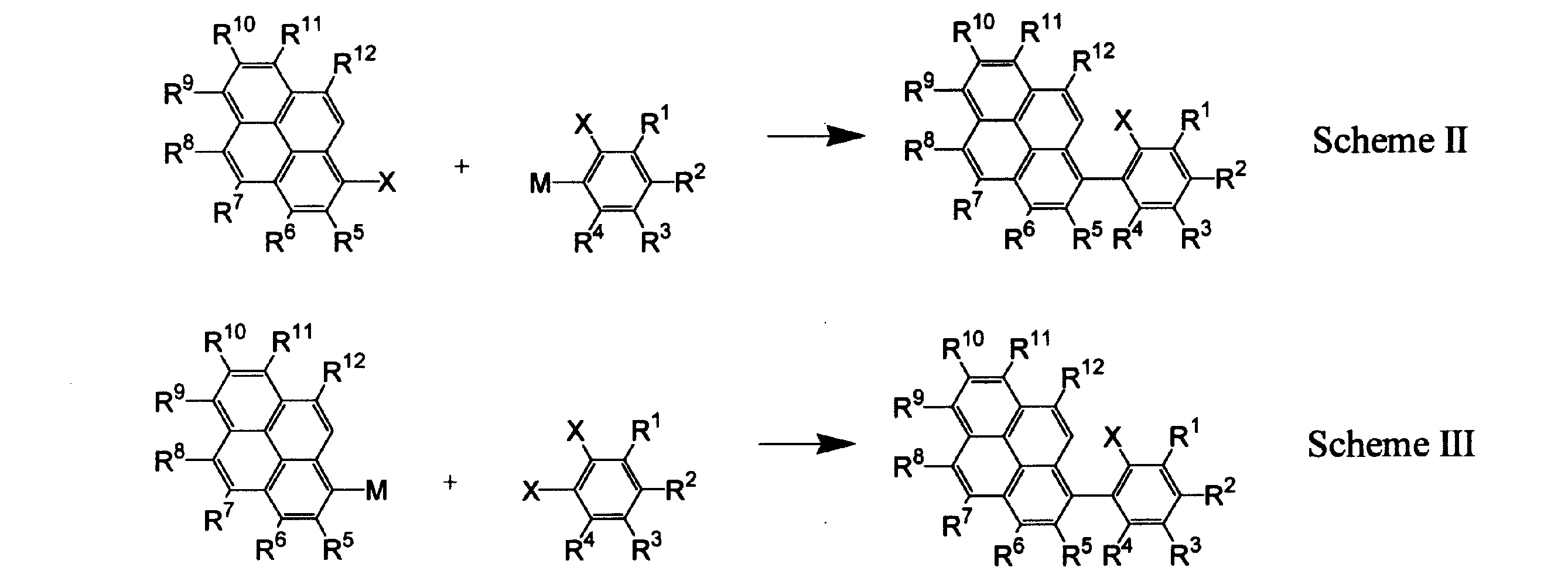
本発明のインデノピレン化合物は有機薄膜太陽電池用材料として用いることができる。この場合、有機薄膜太陽電池の部材(層)は本発明のインデノピレン化合物単独で形成されていてもよいし、本発明のインデノピレン化合物と他の成分との混合物から形成されていてもよい。本発明のインデノピレン化合物を用いる有機薄膜太陽電池は、高効率の光電変換特性を示す。 <Organic thin film solar cell>
The indenopyrene compound of the present invention can be used as a material for organic thin film solar cells. In this case, the member (layer) of the organic thin film solar cell may be formed of the indenopyrene compound of the present invention alone or may be formed of a mixture of the indenopyrene compound of the present invention and other components. The organic thin film solar cell using the indenopyrene compound of the present invention exhibits highly efficient photoelectric conversion characteristics.
本発明の有機薄膜太陽電池のセル構造としては、具体的には、安定な絶縁性基板上に下記の構成を有する構造が挙げられる。
(1)下部電極/有機化合物層/上部電極
(2)下部電極/p層/n層/上部電極
(3)下部電極/p層/i層(p層の材料とn層の材料の混合層)/n層/上部電極
(4)下部電極/p層の材料とn層の材料の混合層/上部電極
(5)下部電極/[p層/(i層/)n層の繰り返し層]/上部電極
及び上記(2)、(3)の構成のp層とn層を置換した構造が挙げられる。 The cell structure of the organic thin film solar cell of the present invention is not particularly limited as long as it is a structure containing the organic thin film solar cell material of the present invention between a pair of electrodes. In particular, it is suitably used as a component of the p layer.
Specific examples of the cell structure of the organic thin film solar cell of the present invention include a structure having the following configuration on a stable insulating substrate.
(1) Lower electrode / organic compound layer / upper electrode (2) Lower electrode / p layer / n layer / upper electrode (3) Lower electrode / p layer / i layer (mixed layer of p layer material and n layer material) ) / N layer / upper electrode (4) lower electrode / mixed layer of p layer material and n layer material / upper electrode (5) lower electrode / [p layer / (i layer /) repetitive layer of n layer] / The structure which substituted the upper electrode and the p layer of the structure of said (2), (3), and n layer is mentioned.
(6)下部電極/バッファー層/有機化合物層/上部電極
(7)下部電極/有機化合物層/バッファー層/上部電極
(8)下部電極/バッファー層/有機化合物層/バッファー層/上部電極 Moreover, you may provide a buffer layer between electrodes as needed. For example, as a specific example, when a buffer layer is provided in the configuration (1), a structure having the following configuration can be given.
(6) Lower electrode / buffer layer / organic compound layer / upper electrode (7) Lower electrode / organic compound layer / buffer layer / upper electrode (8) Lower electrode / buffer layer / organic compound layer / buffer layer / upper electrode
本発明の有機薄膜太陽電池においては、有機薄膜太陽電池を構成するいずれかの部材(層)に本発明の有機薄膜太陽電池用材料を含有していればよい。また、本発明の材料を含有する部材(層)は他の成分を含んでいてもよい。本発明の有機薄膜太陽電池用材料を含まない層の材料や、本発明の有機薄膜太陽電池用材料と混合する層の材料としては、有機薄膜太陽電池で使用される公知の材料を使用することができる。
次に、上記構成において使用し得る各部材(層)について説明する。 The material for an organic thin film solar cell of the present invention can be used as a material for an organic compound layer, a p layer, an n layer, an i layer, and a buffer layer in the organic thin film solar cell having the above structure, for example.
In the organic thin film solar cell of this invention, the organic thin film solar cell material of this invention should just be contained in any member (layer) which comprises an organic thin film solar cell. Moreover, the member (layer) containing the material of this invention may contain the other component. As the material of the layer not including the organic thin film solar cell material of the present invention and the material of the layer mixed with the organic thin film solar cell material of the present invention, a known material used in the organic thin film solar cell should be used. Can do.
Next, each member (layer) that can be used in the above configuration will be described.
下部電極、上部電極の材料に特に制限はなく、公知の導電性材料を使用できる。
例えば、p層と接続する電極としては、錫ドープ酸化インジウム(ITO)や金(Au)、オスミウム(Os)、パラジウム(Pd)等の金属が使用できる。また、n層と接続する電極としては、銀(Ag)、アルミニウム(Al)、インジウム(In)、カルシウム(Ca)、白金(Pt)、リチウム(Li)等の一成分金属や、マグネシウム(Mg)-Ag、Mg-In、Al-Li等の二成分金属、さらには、上記のp層と接続する電極として例示した金属が使用できる。
なお、一対の電極構成の好ましい構成は、電極部の一方が仕事関数の大きな金属を含み、他方は仕事関数の小さな金属を含む構成である。仕事関数の大きな電極材料としては、ITO、Os、Pd等であり、仕事関数の小さな電極材料としては、Al、In、Mg-Agの合金、Ca、Li、Mg等である。 (Lower electrode, upper electrode)
There is no restriction | limiting in particular in the material of a lower electrode and an upper electrode, A well-known electroconductive material can be used.
For example, a metal such as tin-doped indium oxide (ITO), gold (Au), osmium (Os), or palladium (Pd) can be used as the electrode connected to the p layer. In addition, as an electrode connected to the n layer, a single component metal such as silver (Ag), aluminum (Al), indium (In), calcium (Ca), platinum (Pt), lithium (Li), magnesium (Mg) ) -Ag, Mg-In, Al-Li, and other binary metals, as well as the metals exemplified as the electrode connected to the p layer can be used.
Note that a preferable configuration of the pair of electrode configurations is a configuration in which one of the electrode portions includes a metal having a high work function and the other includes a metal having a low work function. The electrode material having a large work function is ITO, Os, Pd, or the like, and the electrode material having a small work function is an alloy of Al, In, Mg—Ag, Ca, Li, Mg, or the like.
膜厚は材料により適宜選択可能であるが、好ましくは1nm~10μmであり、より好ましくは5nm~1μmである。 In order to obtain highly efficient photoelectric conversion characteristics, it is desirable that at least one surface of the solar cell be sufficiently transparent in the sunlight spectrum. For that purpose, a known conductive material is used, and an electrode may be formed by a method such as vapor deposition or sputtering so as to ensure a predetermined translucency. The light transmittance of the electrode on the light receiving surface is preferably 10% or more, more preferably 60% or more, and still more preferably 90% or more.
The film thickness can be appropriately selected depending on the material, but is preferably 1 nm to 10 μm, more preferably 5 nm to 1 μm.
上記有機化合物層とは電極間の層が1層である場合の当該層を指す。本発明の有機薄膜太陽電池用材料を使用する場合の構成としては、「下部電極/本発明の有機薄膜太陽電池用材料の単独層/上部電極」や、「下部電極/本発明の有機薄膜太陽電池用材料とn層材料またはp層材料の混合層/上部電極」が挙げられる。 (Organic compound layer)
The said organic compound layer refers to the said layer in case the layer between electrodes is one layer. The constitution when using the organic thin film solar cell material of the present invention is “lower electrode / single layer of organic thin film solar cell material of the present invention / upper electrode” or “lower electrode / organic thin film solar cell of the present invention”. A mixed layer / upper electrode of battery material and n-layer material or p-layer material ”.
本発明の有機薄膜太陽電池用材料をp層に用いるときは、n層は特に限定されないが、電子受容体としての機能を有する化合物が好ましい。例えば低分子有機化合物であれば、C60、C70等のフラーレン誘導体、カーボンナノチューブ、ペリレン誘導体、多環キノン、キナクリドン等が挙げられ、高分子化合物ではCN-ポリ(フェニレン-ビニレン)、MEH-CN-PPV、-CN基又はCF3基含有ポリマー、ポリ(フルオレン)誘導体等を挙げることができる。電子の移動度が高い材料が好ましく、電子親和力が小さい材料がさらに好ましい。このように電子親和力の小さい材料をn層として組み合わせることで充分な開放端電圧を実現することができる。また、無機化合物であれば、n型特性の無機半導体化合物を挙げることができる。具体的には、n-Si、GaAs、CdS、PbS、CdSe、InP、Nb2O5,WO3,Fe2O3等のドーピング半導体及び化合物半導体、また、二酸化チタン(TiO2)、一酸化チタン(TiO)、三酸化二チタン(Ti2O3)等の酸化チタン、酸化亜鉛(ZnO)、酸化スズ(SnO2)等の導電性酸化物が挙げられ、これらのうちの1種又は2種以上を組み合わせて用いてもよい。好ましくは、酸化チタン、特に好ましくは、二酸化チタンを用いる。 (P layer, n layer, i layer)
When the organic thin film solar cell material of the present invention is used for the p layer, the n layer is not particularly limited, but a compound having a function as an electron acceptor is preferable. For example, fullerene derivatives such as C 60 and C 70 , carbon nanotubes, perylene derivatives, polycyclic quinones, quinacridones, and the like are exemplified for low molecular organic compounds, and CN-poly (phenylene-vinylene), MEH- CN-PPV, -CN group or CF 3 group-containing polymer, poly (fluorene) derivative and the like can be mentioned. A material having a high electron mobility is preferable, and a material having a low electron affinity is more preferable. Thus, a sufficient open-circuit voltage can be realized by combining materials having a small electron affinity as the n layer. Moreover, if it is an inorganic compound, the inorganic semiconductor compound of an n-type characteristic can be mentioned. Specifically, doped semiconductors and compound semiconductors such as n-Si, GaAs, CdS, PbS, CdSe, InP, Nb 2 O 5 , WO 3 , Fe 2 O 3 , titanium dioxide (TiO 2 ), monoxide Examples include titanium oxide such as titanium (TiO) and dititanium trioxide (Ti 2 O 3 ), and conductive oxides such as zinc oxide (ZnO) and tin oxide (SnO 2 ). You may use combining more than a seed. Preference is given to using titanium oxide, particularly preferably titanium dioxide.
混合してi層を形成する場合は、n層の材料とp層の材料との混合比は、体積比で1:5~5:1が好ましく、1:2~2:1がより好ましく、0.9:1.1~1.1:0.9がさらに好ましい。 When the organic thin film solar cell material of the present invention is used for the i layer, the i layer may be formed by mixing with the p layer compound or the n layer compound, but the material of the present invention is used alone as the i layer. You can also In this case, any of the above exemplary compounds can be used for the p layer or the n layer.
When the i layer is formed by mixing, the mixing ratio of the material of the n layer and the material of the p layer is preferably 1: 5 to 5: 1 by volume ratio, more preferably 1: 2 to 2: 1. 0.9: 1.1 to 1.1: 0.9 is more preferable.
一般に、有機薄膜太陽電池はその総膜厚が薄いため、上部電極と下部電極が短絡し、セル作製の歩留まりが低下することが多い。このような場合には、バッファー層を積層することによってこれを防止することが好ましい。また、発生した電流を効率よく外部に取り出すためにもバッファー層を設けたほうが好ましい。
バッファー層に好ましい化合物としては、膜厚を厚くしても短絡電流が低下しないようにキャリア移動度が充分に高い化合物が好ましい。例えば、低分子化合物であれば下記のNTCDAに代表される芳香族環状酸無水物等が挙げられ、高分子化合物であればポリ(3,4-エチレンジオキシ)チオフェン;下記のポリスチレンスルホネート(PEDOT:PSS)、ポリアニリン;カンファースルホン酸(PANI:CSA)等に代表される公知の導電性高分子等が挙げられる。 (Buffer layer)
In general, an organic thin film solar cell has a thin total film thickness, so that the upper electrode and the lower electrode are short-circuited, and the yield of cell fabrication often decreases. In such a case, it is preferable to prevent this by laminating a buffer layer. Further, it is preferable to provide a buffer layer in order to efficiently extract the generated current to the outside.
As a preferable compound for the buffer layer, a compound having sufficiently high carrier mobility is preferable so that the short-circuit current does not decrease even when the film thickness is increased. For example, an aromatic cyclic acid anhydride represented by the following NTCDA is exemplified for a low molecular compound, and poly (3,4-ethylenedioxy) thiophene; a polystyrene sulfonate (PEDOT) shown below for a high molecular compound. : PSS), polyaniline; known conductive polymers represented by camphorsulfonic acid (PANI: CSA) and the like.


バッファー層の膜厚は、好ましくは1nm~3μmであり、より好ましくは5nm~1μmである。 Furthermore, you may use the inorganic compound illustrated as a material of n layer for a buffer layer. Further, CdTe, p-type silicon (p-Si), SiC, GaAs, WO 3 or the like, which are known inorganic compounds having p-type characteristics, may be used.
The thickness of the buffer layer is preferably 1 nm to 3 μm, more preferably 5 nm to 1 μm.
基板は、通常、有機薄膜太陽電池に用いられる基板でよい。機械的、熱的強度を有し、透明性を有するガラス基板や透明性樹脂フィルムを使用することが好ましい。
透明性樹脂フィルムとしては、ポリエチレン、エチレン-酢酸ビニル共重合体、エチレン-ビニルアルコール共重合体、ポリプロピレン、ポリスチレン、ポリメチルメタアクリレート、ポリ塩化ビニル、ポリビニルアルコール、ポリビニルブチラール、ナイロン、ポリエーテルエーテルケトン、ポリサルホン、ポリエーテルサルフォン、テトラフルオロエチレン-パーフルオロアルキルビニルエーテル共重合体、ポリビニルフルオライド、テトラフルオロエチレン-エチレン共重合体、テトラフルオロエチレン-ヘキサフルオロプロピレン共重合体、ポリクロロトリフルオロエチレン、ポリビニリデンフルオライド、ポリエステル、ポリカーボネート、ポリウレタン、ポリイミド、ポリエーテルイミド、ポリイミド、ポリプロピレン等が挙げられる。 (substrate)
The substrate may be a substrate usually used for an organic thin film solar cell. It is preferable to use a glass substrate or a transparent resin film having mechanical and thermal strength and transparency.
Transparent resin films include polyethylene, ethylene-vinyl acetate copolymer, ethylene-vinyl alcohol copolymer, polypropylene, polystyrene, polymethyl methacrylate, polyvinyl chloride, polyvinyl alcohol, polyvinyl butyral, nylon, polyether ether ketone. , Polysulfone, polyethersulfone, tetrafluoroethylene-perfluoroalkyl vinyl ether copolymer, polyvinyl fluoride, tetrafluoroethylene-ethylene copolymer, tetrafluoroethylene-hexafluoropropylene copolymer, polychlorotrifluoroethylene, Polyvinylidene fluoride, polyester, polycarbonate, polyurethane, polyimide, polyetherimide, polyimide, polypropylene, etc. It is.
本発明の有機薄膜太陽電池の各層の形成方法に特に制限はなく、真空蒸着、スパッタリング、プラズマ、イオンプレーティング等の乾式成膜法や、スピンコーティング、ディップコート、キャスティング、ロールコート、フローコーティング、インクジェット等の湿式成膜法を適用することができる。この方法により、各層を前記した各層の膜厚に調整することが好ましい。一般に有機薄膜の励起子拡散長は短いことが知られているため、膜厚が厚すぎると励起子がヘテロ界面に到達する前に失活してしまうため光電変換効率が低くなる。膜厚が薄すぎるとピンホール等が発生してしまうため、充分なダイオード特性が得られないため、変換効率が低下する。 (Method for forming each layer of organic thin film solar cell)
There are no particular limitations on the method of forming each layer of the organic thin film solar cell of the present invention, dry deposition methods such as vacuum deposition, sputtering, plasma, ion plating, spin coating, dip coating, casting, roll coating, flow coating, A wet film formation method such as ink jet can be applied. By this method, it is preferable to adjust each layer to the thickness of each layer described above. Since it is generally known that the exciton diffusion length of an organic thin film is short, if the film thickness is too thick, the exciton is deactivated before reaching the heterointerface, resulting in low photoelectric conversion efficiency. If the film thickness is too thin, pinholes and the like are generated, so that sufficient diode characteristics cannot be obtained, resulting in a decrease in conversion efficiency.
上記湿式成膜法を適用する場合、材料を適切な溶媒に溶解又は分散させて発光性有機溶液を調製してから薄膜を形成する。かかる溶媒としては任意の溶媒を使用でき、例えば、ジクロロメタン、ジクロロエタン、クロロホルム、四塩化炭素、テトラクロロエタン、トリクロロエタン、クロロベンゼン、ジクロロベンゼン、クロロトルエン等のハロゲン系炭化水素系溶媒;ジブチルエーテル、テトラヒドロフラン、ジオキサン、アニソール等のエーテル系溶媒;メタノールやエタノール、プロパノール、ブタノール、ペンタノール、ヘキサノール、シクロヘキサノール、メチルセロソルブ、エチルセロソルブ、エチレングリコール等のアルコール系溶媒;ベンゼン、トルエン、キシレン、エチルベンゼン、ヘキサン、オクタン、デカン、テトラリン等の炭化水素系溶媒;酢酸エチル、酢酸ブチル、酢酸アミル等のエステル系溶媒等が挙げられる。これらの中でも、炭化水素系溶媒又はエーテル系溶媒が好ましい。また、これらの溶媒は、単独で使用しても複数混合して用いてもよい。なお、溶媒は特にこれらに限定されるものではない。 When the dry film forming method is applied, it is preferable to heat evaporate the material using a resistance heating method. Moreover, when forming a mixed layer, the film-forming method by simultaneous vapor deposition from a several evaporation source is preferable, for example. During film formation, it is preferable to control the substrate temperature to be constant.
When the wet film forming method is applied, a thin film is formed after preparing a light-emitting organic solution by dissolving or dispersing the material in an appropriate solvent. As such a solvent, any solvent can be used, for example, halogenated hydrocarbon solvents such as dichloromethane, dichloroethane, chloroform, carbon tetrachloride, tetrachloroethane, trichloroethane, chlorobenzene, dichlorobenzene, chlorotoluene; dibutyl ether, tetrahydrofuran, dioxane Ether solvents such as anisole; alcohol solvents such as methanol, ethanol, propanol, butanol, pentanol, hexanol, cyclohexanol, methyl cellosolve, ethyl cellosolve, ethylene glycol; benzene, toluene, xylene, ethylbenzene, hexane, octane, Examples thereof include hydrocarbon solvents such as decane and tetralin; ester solvents such as ethyl acetate, butyl acetate and amyl acetate. Among these, hydrocarbon solvents or ether solvents are preferable. These solvents may be used alone or in combination. The solvent is not particularly limited to these.
また、添加剤としては、酸化防止剤、紫外線吸収剤、可塑剤等が挙げられる。 In the present invention, in any organic thin film layer of the organic thin film solar cell, an appropriate resin or additive may be contained in order to improve film formability and prevent pinholes in the film. Usable resins include polystyrene, polycarbonate, polyarylate, polyester, polyamide, polyurethane, polysulfone, polymethyl methacrylate, polymethyl acrylate, cellulose and other insulating resins and copolymers thereof; poly-N-vinylcarbazole And photoconductive resins such as polysilane; and conductive resins such as polythiophene and polypyrrole.
Examples of the additive include an antioxidant, an ultraviolet absorber, and a plasticizer.
なお、各例において、ソーラーシミュレーター(装置名「SS-50XIL」、英弘精機株式会社製)を用いて、AM1.5条件(光強度100mW/cm2)下で、I-V特性を測定し、開放端電圧(Voc)、短絡電流密度(Jsc)、曲線因子(FF)、変換効率(η)を求めた。同じPin(光強度)において、Voc、Jsc及びFFがいずれも大きな化合物ほど優れた変換効率を示す。なお、光電変換効率は下記式によって導出した。 EXAMPLES Next, although an Example demonstrates this invention still in detail, this invention is not limited at all by these examples.
In each example, the IV characteristics were measured under AM1.5 conditions (light intensity 100 mW / cm 2 ) using a solar simulator (device name “SS-50XIL”, manufactured by Eihiro Seiki Co., Ltd.) The open circuit voltage (Voc), short circuit current density (Jsc), fill factor (FF), and conversion efficiency (η) were determined. For the same Pin (light intensity), compounds with larger Voc, Jsc, and FF all exhibit better conversion efficiency. The photoelectric conversion efficiency was derived from the following formula.

以下の合成経路で、下記インデノピレン化合物Aを製造した。 [Production Example 1]
The following indenopyrene compound A was produced by the following synthesis route.

2,4-ジブロモアニリン(10g,40mmol)を塩酸水(濃塩酸40ml+水30ml)に懸濁し、氷/食塩浴で-8℃に冷却した。これに亜硝酸ナトリウム水溶液(3.0g,43mmol,1.1eq./15ml)を10分かけて徐々に滴下し、-10℃~0℃で30分撹拌しジアゾニウム塩を調整した。反応液をヨウ化カリウム水溶液(60g,0.36mol,9eq./180ml)に室温で20分かけて徐々に滴下した。反応混合物を室温で3時間撹拌し、ジクロロメタン(200ml)を加え、続いて亜硫酸水素ナトリウム(2g)を加えて発生したヨウ素を失活させた。有機層を分取し、10%亜硫酸水素ナトリウム水溶液(100ml)、飽和食塩水(30ml)で洗浄、無水硫酸マグネシウムで乾燥、溶媒留去して赤色液体を得た。これをカラムクロマトグラフィ(シリカゲル/ヘキサン)で精製して白色固体(11.0g,76%)を得た。
1H-NMR(400MHz,CDCl3,TMS)δ7.11(1H,dd,J=8Hz,2Hz),7.69(1H,d,J=8Hz),7.76(1H,d,J=2Hz) Synthesis of Intermediate A1 2,4-Dibromoaniline (10 g, 40 mmol) was suspended in aqueous hydrochloric acid (concentrated hydrochloric acid 40 ml + water 30 ml) and cooled to −8 ° C. in an ice / salt bath. A sodium nitrite aqueous solution (3.0 g, 43 mmol, 1.1 eq./15 ml) was gradually added dropwise thereto over 10 minutes, and the mixture was stirred at −10 ° C. to 0 ° C. for 30 minutes to prepare a diazonium salt. The reaction solution was gradually added dropwise to an aqueous potassium iodide solution (60 g, 0.36 mol, 9 eq./180 ml) at room temperature over 20 minutes. The reaction mixture was stirred at room temperature for 3 hours, dichloromethane (200 ml) was added followed by sodium bisulfite (2 g) to quench the generated iodine. The organic layer was separated, washed with a 10% aqueous sodium bisulfite solution (100 ml) and saturated brine (30 ml), dried over anhydrous magnesium sulfate and evaporated to give a red liquid. This was purified by column chromatography (silica gel / hexane) to obtain a white solid (11.0 g, 76%).
1 H-NMR (400 MHz, CDCl 3 , TMS) δ 7.11 (1H, dd, J = 8 Hz, 2 Hz), 7.69 (1H, d, J = 8 Hz), 7.76 (1H, d, J = 2Hz)
窒素雰囲気下、中間体A1(2.5g,6.9mmol)、1-ピレンボロン酸(1.7g,6.9mmol)、テトラキス(トリフェニルホスフィン)パラジウム(0)(0.24g,0.21mmol,3%Pd)を1,2-ジメトキシエタン(20ml)に懸濁し、2M炭酸ナトリウム水溶液(2.2g,21mmol,3eq./10ml)を加えて10時間還流した。反応混合物にトルエン(150ml)、水(50ml)を加え、有機層を分取、飽和食塩水(50ml)で洗浄、無水硫酸マグネシウムで乾燥、溶媒留去して淡黄色固体を得た。これをカラムクロマトグラフィ(シリカゲル/ヘキサン+17%ジクロロメタン)で精製して白色固体(1.9g,63%)を得た。
1H-NMR(400MHz,CDCl3,TMS)δ7.32(1H,d,J=8Hz),7.60(1H,dd,J=8Hz,2Hz),7.68(1H,d,J=9Hz),7.83(1H,d,J=8Hz),7.96-8.02(3H,m),8.10(2H,s),8.16(1H,d,J=8Hz),8.20(1H,d,J=8Hz),8.21(1H,d,J=8Hz) Synthesis of Intermediate A2 Under a nitrogen atmosphere, intermediate A1 (2.5 g, 6.9 mmol), 1-pyreneboronic acid (1.7 g, 6.9 mmol), tetrakis (triphenylphosphine) palladium (0) (0.24 g) , 0.21 mmol, 3% Pd) was suspended in 1,2-dimethoxyethane (20 ml), 2M aqueous sodium carbonate solution (2.2 g, 21 mmol, 3 eq./10 ml) was added, and the mixture was refluxed for 10 hours. Toluene (150 ml) and water (50 ml) were added to the reaction mixture, the organic layer was separated, washed with saturated brine (50 ml), dried over anhydrous magnesium sulfate, and the solvent was distilled off to obtain a pale yellow solid. This was purified by column chromatography (silica gel / hexane + 17% dichloromethane) to obtain a white solid (1.9 g, 63%).
1 H-NMR (400 MHz, CDCl 3 , TMS) δ 7.32 (1H, d, J = 8 Hz), 7.60 (1H, dd, J = 8 Hz, 2 Hz), 7.68 (1H, d, J = 9 Hz), 7.83 (1 H, d, J = 8 Hz), 7.96-8.02 (3 H, m), 8.10 (2 H, s), 8.16 (1 H, d, J = 8 Hz) , 8.20 (1H, d, J = 8 Hz), 8.21 (1H, d, J = 8 Hz)
窒素雰囲気下、中間体A2(3.3g,7.6mmol)、ジフェニルアミン(1.4g,8.3mmol,1.1eq.)、トリス(ジベンジリデンアセトン)ジパラジウム(0)(0.10g,0.11mmol,3%Pd)、2,2’-ビス(ジフェニルホスフィノ)-1,1’-ビナフチル(BINAP,0.20g,0.32mmol,1.5eq. to Pd)、ナトリウムt-ブトキシド(1.0g,10mmol,1.4eq.)を無水トルエン(20ml)に懸濁し、10時間還流した。反応混合物をシリカゲルパッドを通してろ別し、トルエン(200ml)で洗浄した。ろ液を溶媒留去して得られた褐色オイルをカラムクロマトグラフィ(シリカゲル/ヘキサン+17%ジクロロメタン、続いてヘキサン+33%ジクロロメタン)で精製して淡橙色固体(1.7g,43%)を得た。
1H-NMR(400MHz,CDCl3,TMS)δ7.09-7.15(3H,m),7.23-7.25(4H,m),7.29(1H,dd,J=9Hz,2Hz),7.35(4H,t,J=8Hz),7.50(1H,s),7.87(1H,d,J=9Hz),7.93(1H,dd,J=8Hz,2Hz),8.01(1H,dt,J=8Hz,1Hz),8.05(1H,d,J=9Hz),8.10(2H,s),8.17-8.23(3H,m) Synthesis of Intermediate A3 Under a nitrogen atmosphere, intermediate A2 (3.3 g, 7.6 mmol), diphenylamine (1.4 g, 8.3 mmol, 1.1 eq.), Tris (dibenzylideneacetone) dipalladium (0) ( 0.10 g, 0.11 mmol, 3% Pd), 2,2′-bis (diphenylphosphino) -1,1′-binaphthyl (BINAP, 0.20 g, 0.32 mmol, 1.5 eq. To Pd), Sodium t-butoxide (1.0 g, 10 mmol, 1.4 eq.) Was suspended in anhydrous toluene (20 ml) and refluxed for 10 hours. The reaction mixture was filtered off through a silica gel pad and washed with toluene (200 ml). The filtrate was evaporated and the brown oil obtained was purified by column chromatography (silica gel / hexane + 17% dichloromethane, followed by hexane + 33% dichloromethane) to give a pale orange solid (1.7 g, 43%).
1 H-NMR (400 MHz, CDCl 3 , TMS) δ 7.09-7.15 (3H, m), 7.23-7.25 (4H, m), 7.29 (1H, dd, J = 9 Hz, 2 Hz), 7.35 (4 H, t, J = 8 Hz), 7.50 (1 H, s), 7.87 (1 H, d, J = 9 Hz), 7.93 (1 H, dd, J = 8 Hz, 2 Hz), 8.01 (1H, dt, J = 8 Hz, 1 Hz), 8.05 (1H, d, J = 9 Hz), 8.10 (2H, s), 8.17-8.23 (3H, m)
窒素雰囲気下、中間体A3(1.7g,3.2mmol)、ジクロロビス(トリフェニルホスフィン)パラジウム(II)(0.23g,0.33mmol,10%Pd)、1,8-ジアザビシクロ[5.4.0]-7-ウンデセン(0.7g,4.6mmol,1.4eq.)を無水DMF(15ml)に溶かし、140℃で11時間撹拌した。反応混合物をトルエン(150ml)で希釈し、水(100ml)、飽和食塩水(50ml)で洗浄、無水硫酸マグネシウムで乾燥、溶媒留去して得られた赤色個体をカラムクロマトグラフィ(シリカゲル/ヘキサン+10%ジクロロメタン、続いてヘキサン+17%ジクロロメタン)で精製して橙色固体(1.2g,85%)を得た。これをエタノール(30ml)+トルエン(100ml)で再結晶して橙色針状晶(1.0g)を得た。
1H-NMR(400MHz,CDCl3,TMS)δ7.06(2H,t,J=7Hz),7.18-7.25(5H,m),7.31(4H,t,J=8Hz),7.87-7.89(2H,m),7.99(1H,d,J=8Hz),8.03(1H,d,J=8Hz),8.10(1H,d,J=9Hz),8.20(1H,d,J=8Hz),8.22(1H,d,J=7Hz),8.28(1H,d,J=8Hz),8.31(1H,d,J=8Hz),8.42(1H,s)
FDMS,計算値C34H21N=443、実測値m/z=443(M+,100)
HPLC,99.5%(UV254,面積%)
上記の方法で得られた固体(1.0g)を280℃/3.2x10-4Paで昇華精製することにより赤色アモルファス固体(0.9g)を得た。
HPLC,99.6%(UV254,面積%)
融点207℃(DSC)
吸収極大波長(CH2Cl2)、471nm
蛍光極大波長(CH2Cl2)、597nm Synthesis of indenopyrene compound A (hereinafter sometimes abbreviated as compound A) Under a nitrogen atmosphere, intermediate A3 (1.7 g, 3.2 mmol), dichlorobis (triphenylphosphine) palladium (II) (0.23 g,. 33 mmol, 10% Pd), 1,8-diazabicyclo [5.4.0] -7-undecene (0.7 g, 4.6 mmol, 1.4 eq.) Was dissolved in anhydrous DMF (15 ml) and dissolved at 140 ° C. at 11 ° C. Stir for hours. The reaction mixture was diluted with toluene (150 ml), washed with water (100 ml) and saturated brine (50 ml), dried over anhydrous magnesium sulfate, and the solvent was distilled off. The solid obtained was subjected to column chromatography (silica gel / hexane + 10% Purification with dichloromethane followed by hexane + 17% dichloromethane) gave an orange solid (1.2 g, 85%). This was recrystallized with ethanol (30 ml) + toluene (100 ml) to obtain orange needle crystals (1.0 g).
1 H-NMR (400 MHz, CDCl 3 , TMS) δ 7.06 (2H, t, J = 7 Hz), 7.18-7.25 (5H, m), 7.31 (4H, t, J = 8 Hz) , 7.87-7.89 (2H, m), 7.99 (1H, d, J = 8Hz), 8.03 (1H, d, J = 8Hz), 8.10 (1H, d, J = 9 Hz), 8.20 (1 H, d, J = 8 Hz), 8.22 (1 H, d, J = 7 Hz), 8.28 (1 H, d, J = 8 Hz), 8.31 (1 H, d, J = 8Hz), 8.42 (1H, s)
FDMS, calculated value C 34 H 21 N = 443, measured value m / z = 443 (M + , 100)
HPLC, 99.5% (UV254, area%)
The solid (1.0 g) obtained by the above method was purified by sublimation at 280 ° C./3.2×10 −4 Pa to obtain a red amorphous solid (0.9 g).
HPLC, 99.6% (UV254, area%)
Melting point 207 ° C (DSC)
Absorption maximum wavelength (CH 2 Cl 2 ), 471 nm
Fluorescence maximum wavelength (CH 2 Cl 2 ), 597 nm
以下の合成経路で、下記インデノピレン化合物Bを製造した。 [Production Example 2]
The following indenopyrene compound B was produced by the following synthesis route.

窒素雰囲気下、1-ブロモピレン(5.0g,18mmol)、2,5-ジクロロフェニルボロン酸(4.1g,21mmol,1.2eq.)、テトラキス(トリフェニルホスフィン)パラジウム(0)(0.40g,0.35mmol,2%Pd)を1,2-ジメトキシエタン(65ml)に懸濁し、2M炭酸ナトリウム水溶液(6.7g,63mmol,3eq./30ml)を加えて10時間還流した。反応混合物にトルエン(100ml)、水(50ml)を加え、有機層を分取、飽和食塩水(50ml)で洗浄、無水硫酸マグネシウムで乾燥、溶媒留去して淡黄色オイルを得た。これをカラムクロマトグラフィ(シリカゲル/ヘキサン+17%ジクロロメタン)で精製して白色固体(5.2g,83%)を得た。
1H-NMR(400MHz,CDCl3,TMS)δ7.40(1H,dd,J=9Hz,2Hz),7.49(1H,d,J=2Hz),7.51(1H,d,J=9Hz),7.71(1H,d,J=9Hz),7.86(1H,d,J=8Hz),8.00(1H,t,J=8Hz),8.02(1H,d,J=9Hz),8.08(1H,d,J=9Hz),8.11(1H,d,J=9Hz),8.16(1H,d,J=8Hz),8.20(1H,d,J=7Hz),8.21(1H,d,J=8Hz) Synthesis of Intermediate B1 Under nitrogen atmosphere, 1-bromopyrene (5.0 g, 18 mmol), 2,5-dichlorophenylboronic acid (4.1 g, 21 mmol, 1.2 eq.), Tetrakis (triphenylphosphine) palladium (0) (0.40 g, 0.35 mmol, 2% Pd) was suspended in 1,2-dimethoxyethane (65 ml), 2M aqueous sodium carbonate solution (6.7 g, 63 mmol, 3 eq./30 ml) was added, and the mixture was refluxed for 10 hours. . Toluene (100 ml) and water (50 ml) were added to the reaction mixture, the organic layer was separated, washed with saturated brine (50 ml), dried over anhydrous magnesium sulfate, and the solvent was distilled off to obtain a pale yellow oil. This was purified by column chromatography (silica gel / hexane + 17% dichloromethane) to obtain a white solid (5.2 g, 83%).
1 H-NMR (400 MHz, CDCl 3 , TMS) δ 7.40 (1H, dd, J = 9 Hz, 2 Hz), 7.49 (1H, d, J = 2 Hz), 7.51 (1H, d, J = 9 Hz), 7.71 (1 H, d, J = 9 Hz), 7.86 (1 H, d, J = 8 Hz), 8.00 (1 H, t, J = 8 Hz), 8.02 (1 H, d, J = 9 Hz), 8.08 (1H, d, J = 9 Hz), 8.11 (1H, d, J = 9 Hz), 8.16 (1H, d, J = 8 Hz), 8.20 (1H, d, J = 7 Hz), 8.21 (1H, d, J = 8 Hz)
窒素雰囲気下、中間体B1(5.2g,15mmol)、ジフェニルアミン(2.8g,17mmol,1.1eq.)、トリス(ジベンジリデンアセトン)ジパラジウム(0)(0.14,0.15mmol,2%Pd)、トリt-ブチルホスフィン/トルエン溶液(66wt%,0.07ml,0.23mmol,0.8eq.to Pd)、ナトリウムt-ブトキシド(2.0g,21mmol,1.4eq.)を無水トルエン(40ml)に懸濁し、10時間還流した。反応混合物をシリカゲルパッドを通してろ別し、トルエン(200ml)で洗浄した。ろ液を溶媒留去して得られた褐色オイルをカラムクロマトグラフィ(シリカゲル/ヘキサン+17%ジクロロメタン、続いてヘキサン+33%ジクロロメタン)で精製して黄橙色アモルファス固体(5.9g,82%)を得た。
1H-NMR(400MHz,CDCl3,TMS)δ7.05(2H,t,J=7Hz),7.18-7.33(11H,m),7.74-8.14(6H,m),8.20-8.26(3H,m) Synthesis of Intermediate B2 Under a nitrogen atmosphere, intermediate B1 (5.2 g, 15 mmol), diphenylamine (2.8 g, 17 mmol, 1.1 eq.), Tris (dibenzylideneacetone) dipalladium (0) (0.14, 0.15 mmol, 2% Pd), tri-t-butylphosphine / toluene solution (66 wt%, 0.07 ml, 0.23 mmol, 0.8 eq. To Pd), sodium t-butoxide (2.0 g, 21 mmol, 1. 4 eq.) Was suspended in anhydrous toluene (40 ml) and refluxed for 10 hours. The reaction mixture was filtered off through a silica gel pad and washed with toluene (200 ml). The brown oil obtained by distilling off the filtrate was purified by column chromatography (silica gel / hexane + 17% dichloromethane, followed by hexane + 33% dichloromethane) to give a yellow-orange amorphous solid (5.9 g, 82%). .
1 H-NMR (400 MHz, CDCl 3 , TMS) δ 7.05 (2H, t, J = 7 Hz), 7.18-7.33 (11H, m), 7.74-8.14 (6H, m) , 8.20-8.26 (3H, m)
窒素雰囲気下、中間体B2(5.9g,12mmol)、トリス(ジベンジリデンアセトン)ジパラジウム(0)(0.28g,0.31mmol,5%Pd)、トリt-ブチルホスフィン/トルエン溶液(66wt%,0.19ml,0.62mmol,1eq. to Pd)、1,8-ジアザビシクロ[5.4.0]-7-ウンデセン(2.6g,17mmol,1.4eq.)を無水DMF(30ml)に溶かし、140℃で11時間撹拌した。反応混合物をトルエン(150ml)で希釈し、水(100ml)、飽和食塩水(50ml)で洗浄、無水硫酸マグネシウムで乾燥、溶媒留去して得られた赤褐色個体をカラムクロマトグラフィ(シリカゲル/ヘキサン+10%ジクロロメタン、続いてヘキサン+33%ジクロロメタン)で精製して橙色固体(3.5g,66%)を得た。これをエタノール(20ml)+トルエン(50ml)で再結晶して橙色板状晶(1.2g,23%)を得た。
1H-NMR(400MHz,CDCl3,TMS)δ7.07(1H,d,J=7Hz),7.12(1H,dd,J=8Hz,2Hz),7.23(4H,d,J=7Hz),7.31(4H,t,J=7Hz),7.76(1H,d,J=2Hz),7.97(1H,d,J=8Hz),8.01-8.12(3H,m),8.16-8.25(3H,m),8.38(1H,d,J=7Hz),8.46(1H,s)
FDMS,計算値C34H21N=443、実測値m/z=443(M+,100)
HPLC,99.6%(UV254,面積%)
上記方法で得られた固体(1.0g)を300℃/1.5x10-4Paで昇華精製することにより橙色固体(0.87g)を得た。
HPLC,99.8%(UV254,面積%)
融点234℃(DSC)
吸収極大波長(CH2Cl2)、420nm
蛍光極大波長(CH2Cl2)、569nm Synthesis of indenopyrene compound B (hereinafter may be abbreviated as compound B) Under nitrogen atmosphere, intermediate B2 (5.9 g, 12 mmol), tris (dibenzylideneacetone) dipalladium (0) (0.28 g, 0.31 mmol) , 5% Pd), tri-t-butylphosphine / toluene solution (66 wt%, 0.19 ml, 0.62 mmol, 1 eq. To Pd), 1,8-diazabicyclo [5.4.0] -7-undecene (2 .6 g, 17 mmol, 1.4 eq.) Was dissolved in anhydrous DMF (30 ml) and stirred at 140 ° C. for 11 hours. The reaction mixture was diluted with toluene (150 ml), washed with water (100 ml) and saturated brine (50 ml), dried over anhydrous magnesium sulfate, and evaporated to obtain a reddish brown solid which was subjected to column chromatography (silica gel / hexane + 10% Purification with dichloromethane followed by hexane + 33% dichloromethane) gave an orange solid (3.5 g, 66%). This was recrystallized from ethanol (20 ml) + toluene (50 ml) to obtain orange plate crystals (1.2 g, 23%).
1 H-NMR (400 MHz, CDCl 3 , TMS) δ 7.07 (1H, d, J = 7 Hz), 7.12 (1H, dd, J = 8 Hz, 2 Hz), 7.23 (4H, d, J = 7 Hz), 7.31 (4 H, t, J = 7 Hz), 7.76 (1 H, d, J = 2 Hz), 7.97 (1 H, d, J = 8 Hz), 8.01-8.12 ( 3H, m), 8.16-8.25 (3H, m), 8.38 (1H, d, J = 7 Hz), 8.46 (1H, s)
FDMS, calculated value C 34 H 21 N = 443, measured value m / z = 443 (M + , 100)
HPLC, 99.6% (UV254, area%)
The solid (1.0 g) obtained by the above method was purified by sublimation at 300 ° C./1.5×10 −4 Pa to obtain an orange solid (0.87 g).
HPLC, 99.8% (UV254, area%)
Melting point 234 ° C. (DSC)
Absorption maximum wavelength (CH 2 Cl 2 ), 420 nm
Fluorescence maximum wavelength (CH 2 Cl 2 ), 569 nm
以下の合成経路で、下記インデノピレン化合物Cを製造した。 [Production Example 3]
The following indenopyrene compound C was produced by the following synthesis route.

窒素雰囲気下、1,6-ジブロモピレン(5.0g,14mmol)、ジフェニルアミン(2.3g,14mmol)、トリス(ジベンジリデンアセトン)ジパラジウム(0)(0.19g,0.21mmol,3%Pd)、1,1’-ビス(ジフェニルホスフィノ)フェロセン(DPPF,0.34g,0.61mmol,1.5eq.to Pd)、ナトリウムt-ブトキシド(1.9g,20mmol,1.4eq.)を無水トルエン(40ml)に懸濁させ、11時間還流した。反応混合物をシリカゲルパッドを通してろ別し、トルエン(200ml)で洗浄した。ろ液を溶媒留去して得られた褐色オイルをカラムクロマトグラフィ(シリカゲル/ヘキサン+17%ジクロロメタン、続いてヘキサン+33%ジクロロメタン)で精製して黄色固体(2.0g,32%)を得た。
1H-NMR(400MHz,CDCl3,TMS)6.96(2H,t,J=7Hz),7.06(4H,d,J=7Hz),7.20(4H,t,J=7Hz),7.85(1H,d,J=8Hz),7.86(1H,d,J=9Hz),7.92(1H,d,J=8Hz),8.10-8.21(4H,m),8.41(1H,d,J=9Hz) Synthesis of Intermediate C1 Under a nitrogen atmosphere, 1,6-dibromopyrene (5.0 g, 14 mmol), diphenylamine (2.3 g, 14 mmol), tris (dibenzylideneacetone) dipalladium (0) (0.19 g, 0. 21 mmol, 3% Pd), 1,1′-bis (diphenylphosphino) ferrocene (DPPF, 0.34 g, 0.61 mmol, 1.5 eq. To Pd), sodium t-butoxide (1.9 g, 20 mmol, 1 .4 eq.) Was suspended in anhydrous toluene (40 ml) and refluxed for 11 hours. The reaction mixture was filtered off through a silica gel pad and washed with toluene (200 ml). The filtrate was evaporated and the brown oil obtained was purified by column chromatography (silica gel / hexane + 17% dichloromethane, followed by hexane + 33% dichloromethane) to give a yellow solid (2.0 g, 32%).
1 H-NMR (400 MHz, CDCl 3 , TMS) 6.96 (2H, t, J = 7 Hz), 7.06 (4H, d, J = 7 Hz), 7.20 (4H, t, J = 7 Hz) , 7.85 (1H, d, J = 8 Hz), 7.86 (1H, d, J = 9 Hz), 7.92 (1H, d, J = 8 Hz), 8.10-8.21 (4H, m), 8.41 (1H, d, J = 9 Hz)
窒素雰囲気下、中間体C1(2.0g,4.5mmol)、2-ブロモフェニルボロン酸(1.1g,5.5mmol,1.2eq.)、テトラキス(トリフェニルホスフィン)パラジウム(0)(0.10g,87mol,2%Pd)を1,2-ジメトキシエタン(20ml)に懸濁し、2M炭酸ナトリウム水溶液(1.7g,16mmol,3eq./8ml)を加えて11時間還流した。反応混合物を水(100ml)で希釈し、固体をろ別、水、メタノールで洗浄して黄色固体(2.3g,98%)を得た。
1H-NMR(400MHz,CDCl3,TMS)δ6.95(3H,t,J=7Hz),7.08(4H,d,J=7Hz),7.20(4H,t,J=7Hz),7.33-7.39(1H,m),7.45-7.50(2H,m),7.70(1H,d,J=9Hz),7.80(1H,d,J=8Hz),7.84(1H,d,J=8Hz),7.87(1H,d,J=8Hz),7.97(1H,d,J=9Hz),7.98(1H,d,J=9Hz),8.12-8.16(2H,m),8.19(1H,d,J=9Hz) Synthesis of Intermediate C2 Under nitrogen atmosphere, intermediate C1 (2.0 g, 4.5 mmol), 2-bromophenylboronic acid (1.1 g, 5.5 mmol, 1.2 eq.), Tetrakis (triphenylphosphine) palladium (0) (0.10 g, 87 mol, 2% Pd) was suspended in 1,2-dimethoxyethane (20 ml), 2M aqueous sodium carbonate solution (1.7 g, 16 mmol, 3 eq./8 ml) was added, and the mixture was refluxed for 11 hours. did. The reaction mixture was diluted with water (100 ml), the solid was filtered off and washed with water and methanol to give a yellow solid (2.3 g, 98%).
1 H-NMR (400 MHz, CDCl 3 , TMS) δ 6.95 (3H, t, J = 7 Hz), 7.08 (4H, d, J = 7 Hz), 7.20 (4H, t, J = 7 Hz) , 7.33-7.39 (1H, m), 7.45-7.50 (2H, m), 7.70 (1H, d, J = 9 Hz), 7.80 (1H, d, J = 8 Hz), 7.84 (1 H, d, J = 8 Hz), 7.87 (1 H, d, J = 8 Hz), 7.97 (1 H, d, J = 9 Hz), 7.98 (1 H, d, J = 9 Hz), 8.12-8.16 (2H, m), 8.19 (1H, d, J = 9 Hz)
窒素雰囲気下、中間体C2(2.4g,4.6mmol)、ジクロロビス(トリフェニルホスフィン)パラジウム(II)(0.32g,0.46mmol,10%Pd)、1,8-ジアザビシクロ[5.4.0]-7-ウンデセン(1.0g,6.6mmol,1.4eq.)を無水DMF(20ml)に溶かし、140℃で11時間撹拌した。反応混合物をトルエン(200ml)で希釈し、水(100ml)、飽和食塩水(50ml)で洗浄、無水硫酸マグネシウムで乾燥、溶媒留去して得られた濃褐色オイルをカラムクロマトグラフィ(シリカゲル/ヘキサン+10%ジクロロメタン、続いてヘキサン+17%ジクロロメタン)で精製して黄橙色固体(1.2g,59%)を得た。これをエタノール(30ml)+トルエン(30ml)で再結晶して黄橙色板状晶(0.9g)を得た。
1H-NMR(400MHz,CDCl3,TMS)δ6.99(2H,t,J=7Hz),7.12(4H,d,J=9Hz),7.23(4H,t,J=7Hz),7.41-7.48(2H,m),7.79(1H,d,J=8Hz),7.92(1H,d,J=9Hz),8.01(1H,d,J=7Hz),8.07(1H,d,J=9Hz),8.11(1H,d,J=7Hz),8.13(1H,d,J=8Hz),8.34(1H,dd,J=8Hz,2Hz),8.52(1H,s)
FDMS,計算値C34H21N=443、実測値m/z=443(M+,100)
HPLC,98.6%(UV254,面積%)
上で得られた固体(0.85g)を260℃/4.7x10-4Paで昇華精製することにより黄色固体(0.80g)を得た。
HPLC,98.7%(UV254,面積%)
吸収極大波長(CH2Cl2)、451nm
蛍光極大波長(CH2Cl2)、510nm Synthesis of indenopyrene compound C (hereinafter may be abbreviated as compound C) Under nitrogen atmosphere, intermediate C2 (2.4 g, 4.6 mmol), dichlorobis (triphenylphosphine) palladium (II) (0.32 g, 0. 46 mmol, 10% Pd), 1,8-diazabicyclo [5.4.0] -7-undecene (1.0 g, 6.6 mmol, 1.4 eq.) In anhydrous DMF (20 ml) and dissolved at 140 ° C. at 11 ° C. Stir for hours. The reaction mixture was diluted with toluene (200 ml), washed with water (100 ml) and saturated brine (50 ml), dried over anhydrous magnesium sulfate and evaporated to give a dark brown oil which was subjected to column chromatography (silica gel / hexane + 10 % Dichloromethane, followed by hexane + 17% dichloromethane) to give a yellow-orange solid (1.2 g, 59%). This was recrystallized from ethanol (30 ml) + toluene (30 ml) to obtain yellowish orange plate crystals (0.9 g).
1 H-NMR (400 MHz, CDCl 3 , TMS) δ 699 (2H, t, J = 7 Hz), 7.12 (4H, d, J = 9 Hz), 7.23 (4H, t, J = 7 Hz) , 7.41-7.48 (2H, m), 7.79 (1H, d, J = 8 Hz), 7.92 (1H, d, J = 9 Hz), 8.01 (1H, d, J = 7 Hz), 8.07 (1 H, d, J = 9 Hz), 8.11 (1 H, d, J = 7 Hz), 8.13 (1 H, d, J = 8 Hz), 8.34 (1 H, dd, J = 8Hz, 2Hz), 8.52 (1H, s)
FDMS, calculated value C 34 H 21 N = 443, measured value m / z = 443 (M + , 100)
HPLC, 98.6% (UV254, area%)
The solid (0.85 g) obtained above was purified by sublimation at 260 ° C./4.7×10 −4 Pa to obtain a yellow solid (0.80 g).
HPLC, 98.7% (UV254, area%)
Absorption maximum wavelength (CH 2 Cl 2 ), 451 nm
Fluorescence maximum wavelength (CH 2 Cl 2 ), 510 nm
「25mm×75mm×厚さ0.7mm」のITO透明電極付きガラス基板について、イソプロピルアルコール中で超音波洗浄を5分間行った後、UVオゾン洗浄を30分間行った。洗浄後の透明電極ライン付きガラス基板を真空蒸着装置の基板ホルダーに装着し、まず、下部電極である透明電極ラインが形成されている側の面上に、前記透明電極を覆うようにして、前記化合物Aを抵抗加熱蒸着により1Å/sで成膜(膜厚30nm)した。続けて、この膜上にフラーレン(C60)を抵抗加熱蒸着により1Å/sで成膜(膜厚60nm)し、その上に下記のバソクプロイン(BCP)を抵抗加熱蒸着により1Å/sで成膜(膜厚10nm)した。最後に、連続して対向電極として金属Alを膜厚80nmで蒸着させ、有機薄膜太陽電池を形成した。面積は0.5cm2であった。
得られた有機薄膜太陽電池の性能を第1表に示す。 Example 1
The glass substrate with ITO transparent electrode of “25 mm × 75 mm × thickness 0.7 mm” was subjected to ultrasonic cleaning in isopropyl alcohol for 5 minutes and then UV ozone cleaning for 30 minutes. Attach the glass substrate with the transparent electrode line after cleaning to the substrate holder of the vacuum deposition apparatus, and first cover the transparent electrode on the surface where the transparent electrode line as the lower electrode is formed, Compound A was formed into a film (thickness 30 nm) at 1 蒸 着 / s by resistance heating vapor deposition. Subsequently, fullerene (C 60 ) is deposited on this film by resistance heating vapor deposition at a thickness of 1 Å / s (film thickness 60 nm), and the following bathocuproine (BCP) is deposited by resistance heating vapor deposition at 1 Å / s. (Film thickness 10 nm). Finally, metal Al was continuously deposited as a counter electrode with a film thickness of 80 nm to form an organic thin film solar cell. The area was 0.5 cm 2 .
The performance of the obtained organic thin film solar cell is shown in Table 1.

「25mm×75mm×厚さ0.7mm」のITO透明電極付きガラス基板について、イソプロピルアルコール中で超音波洗浄を5分間行った後、UVオゾン洗浄を30分間行った。洗浄後の透明電極ライン付きガラス基板を真空蒸着装置の基板ホルダーに装着し、まず、下部電極である透明電極ラインが形成されている側の面上に、前記透明電極を覆うようにして、前記化合物Aを抵抗加熱蒸着により1Å/sで成膜(p層:膜厚5nm)した。続けて、この膜上に、化合物Aを0.2Å/s、C60を0.2Å/sで共蒸着し、i層(混合比p:n=1:1、膜厚15nm)を形成した。この上にC60を抵抗加熱蒸着により1Å/sで成膜(n層:膜厚45nm)し、その上に下記のバソクプロイン(BCP)を抵抗加熱蒸着により1Å/sで成膜(バッファー層:膜厚10nm)した。最後に、連続して対向電極として金属Alを膜厚80nmで蒸着させ、有機薄膜太陽電池を形成した。面積は0.5cm2であった。
得られた有機薄膜太陽電池の性能を第1表に示す。 (Example 2)
The glass substrate with ITO transparent electrode of “25 mm × 75 mm × thickness 0.7 mm” was subjected to ultrasonic cleaning in isopropyl alcohol for 5 minutes and then UV ozone cleaning for 30 minutes. Attach the glass substrate with the transparent electrode line after cleaning to the substrate holder of the vacuum deposition apparatus, and first cover the transparent electrode on the surface where the transparent electrode line as the lower electrode is formed, Compound A was formed into a film at 1 蒸 着 / s by resistance heating vapor deposition (p layer: film thickness 5 nm). Subsequently, compound A was co-evaporated at 0.2 Å / s and C 60 was 0.2 Å / s on this film to form an i layer (mixing ratio p: n = 1: 1, film thickness 15 nm). . On top of this, C 60 was formed by resistance heating vapor deposition at 1 Å / s (n layer: film thickness 45 nm), and the following bathocuproine (BCP) was formed thereon by resistance heating vapor deposition at 1 Å / s (buffer layer: (Film thickness 10 nm). Finally, metal Al was continuously deposited as a counter electrode with a film thickness of 80 nm to form an organic thin film solar cell. The area was 0.5 cm 2 .
The performance of the obtained organic thin film solar cell is shown in Table 1.
i層におけるp化合物とn化合物の混合比をp:n=2:1(成膜速度はそれぞれ0.2Å/s、0.1Å/s)とした以外は実施例2と同様にして有機薄膜太陽電池を作製した。得られた有機薄膜太陽電池の性能を第1表に示す。 (Example 3)
The organic thin film was prepared in the same manner as in Example 2 except that the mixing ratio of the p compound and the n compound in the i layer was p: n = 2: 1 (deposition rates were 0.2 Å / s and 0.1 Å / s, respectively). A solar cell was produced. The performance of the obtained organic thin film solar cell is shown in Table 1.
i層におけるp化合物とn化合物の混合比をp:n=1:2(成膜速度はそれぞれ0.1Å/s、0.2Å/s)とした以外は実施例2と同様にして有機薄膜太陽電池を作製した。得られた有機薄膜太陽電池の性能を第1表に示す。 Example 4
An organic thin film was formed in the same manner as in Example 2 except that the mixing ratio of the p compound and the n compound in the i layer was p: n = 1: 2 (deposition rates were 0.1 Å / s and 0.2 Å / s, respectively). A solar cell was produced. The performance of the obtained organic thin film solar cell is shown in Table 1.
実施例1のC60をC70へ変更した以外は実施例1と同様にして有機薄膜太陽電池を作製した。得られた有機薄膜太陽電池の性能を第1表に示す。 (Example 5)
Except for changing the C 60 in Example 1 to C 70 to manufacture an organic thin film solar cell in the same manner as in Example 1. The performance of the obtained organic thin film solar cell is shown in Table 1.

実施例3のC60をC70へ変更し、p層の膜厚を15nm、i層の膜厚を15nm、n層の膜厚を45nmに変更した以外は実施例3と同様にして有機薄膜太陽電池を作製した。得られた有機薄膜太陽電池の性能を第1表に示す。 (Example 6)
The C 60 of Example 3 was changed to C 70, 15nm thickness of the p layer, i layer 15nm thickness of, similarly to the organic thin film as in Example 3 except for changing the thickness of the n-layer to 45nm A solar cell was produced. The performance of the obtained organic thin film solar cell is shown in Table 1.
実施例3のC60をC70へ変更し、p層の膜厚を15nm、i層の膜厚を15nm、n層の膜厚を60nmに変更した以外は実施例3と同様にして有機薄膜太陽電池を作製した。得られた有機薄膜太陽電池の性能を第1表に示す。 (Example 7)
An organic thin film was prepared in the same manner as in Example 3, except that C 60 in Example 3 was changed to C 70 , the thickness of the p layer was changed to 15 nm, the thickness of the i layer was changed to 15 nm, and the thickness of the n layer was changed to 60 nm. A solar cell was produced. The performance of the obtained organic thin film solar cell is shown in Table 1.
実施例1のインデノピレン化合物Aをインデノピレン化合物Bへ変更した以外は実施例1と同様にして有機薄膜太陽電池を作製した。得られた有機薄膜太陽電池の性能を第1表に示す。 (Example 8)
An organic thin-film solar cell was produced in the same manner as in Example 1 except that the indenopyrene compound A in Example 1 was changed to the indenopyrene compound B. The performance of the obtained organic thin film solar cell is shown in Table 1.
実施例5のインデノピレン化合物Aをインデノピレン化合物Bへ変更した以外は実施例5と同様にして有機薄膜太陽電池を作製した。得られた有機薄膜太陽電池の性能を第1表に示す。 Example 9
An organic thin-film solar cell was produced in the same manner as in Example 5 except that the indenopyrene compound A in Example 5 was changed to the indenopyrene compound B. The performance of the obtained organic thin film solar cell is shown in Table 1.
実施例1のインデノピレン化合物Aをインデノピレン化合物Cへ変更した以外は実施例1と同様にして有機薄膜太陽電池を作製した。得られた有機薄膜太陽電池の性能を第1表に示す。 (Example 10)
An organic thin film solar cell was produced in the same manner as in Example 1 except that the indenopyrene compound A in Example 1 was changed to the indenopyrene compound C. The performance of the obtained organic thin film solar cell is shown in Table 1.
実施例1のインデノピレン化合物AをmTPDへ変更した以外は実施例1と同様にして有機薄膜太陽電池を作製した。得られた有機薄膜太陽電池の性能を第1表に示す。 (Comparative Example 1)
An organic thin film solar cell was produced in the same manner as in Example 1 except that the indenopyrene compound A in Example 1 was changed to mTPD. The performance of the obtained organic thin film solar cell is shown in Table 1.
実施例5のインデノピレン化合物AをmTPDへ変更した以外は実施例5と同様にして有機薄膜太陽電池を作製した。得られた有機薄膜太陽電池の性能を第1表に示す。 (Comparative Example 2)
An organic thin film solar cell was produced in the same manner as in Example 5 except that the indenopyrene compound A in Example 5 was changed to mTPD. The performance of the obtained organic thin film solar cell is shown in Table 1.


以下の合成経路で、下記インデノピレン化合物Dを製造した。 [Production Example 4]
The following indenopyrene compound D was produced by the following synthesis route.

2-ブロモ-4-クロロアニリン(10g,48mmol)を塩酸水(濃塩酸50ml+水35ml)に懸濁し、ドライアイス/メタノール浴で-15℃に冷却した。これに亜硝酸ナトリウム水溶液(3.6g,52mmol,1.1eq./20ml)を20分かけて徐々に滴下し、-15℃~0℃で30分撹拌しジアゾニウム塩を調整した。反応液をヨウ化カリウム水溶液(73g,0.44mol,9eq./220ml)に室温で10分かけて徐々に滴下した。反応混合物を室温で6時間撹拌し、一晩放置した。反応混合物にジクロロメタン(200ml)を加え、続いて亜硫酸水素ナトリウム(2g)を加えて発生したヨウ素を失活させた。有機層を分取し、10%亜硫酸水素ナトリウム水溶液(100ml)、飽和食塩水(30ml)で洗浄、無水硫酸マグネシウムで乾燥、溶媒留去して赤色液体を得た。これをカラムクロマトグラフィ(シリカゲル/ヘキサン)で精製して白色針状晶(12.4g,81%)を得た。
1H-NMR(400MHz,CDCl3,TMS)δ6.98(1H,dd,J=8Hz,2Hz),7.61(1H,d,J=2Hz),7.74(1H,d,J=8Hz) Synthesis of Intermediate D1 2-Bromo-4-chloroaniline (10 g, 48 mmol) was suspended in aqueous hydrochloric acid (concentrated hydrochloric acid 50 ml + water 35 ml) and cooled to −15 ° C. in a dry ice / methanol bath. A sodium nitrite aqueous solution (3.6 g, 52 mmol, 1.1 eq./20 ml) was gradually added dropwise thereto over 20 minutes, and the mixture was stirred at −15 ° C. to 0 ° C. for 30 minutes to prepare a diazonium salt. The reaction solution was gradually added dropwise to an aqueous potassium iodide solution (73 g, 0.44 mol, 9 eq./220 ml) at room temperature over 10 minutes. The reaction mixture was stirred at room temperature for 6 hours and left overnight. Dichloromethane (200 ml) was added to the reaction mixture, followed by sodium bisulfite (2 g) to deactivate the generated iodine. The organic layer was separated, washed with a 10% aqueous sodium bisulfite solution (100 ml) and saturated brine (30 ml), dried over anhydrous magnesium sulfate and evaporated to give a red liquid. This was purified by column chromatography (silica gel / hexane) to obtain white needle crystals (12.4 g, 81%).
1 H-NMR (400 MHz, CDCl 3 , TMS) δ 6.98 (1H, dd, J = 8 Hz, 2 Hz), 7.61 (1H, d, J = 2 Hz), 7.74 (1H, d, J = 8Hz)
窒素雰囲気下、中間体D1(12.4g,39mmol)、1-ピレンボロン酸(9.6g,39mmol)、テトラキス(トリフェニルホスフィン)パラジウム(0)(1.4g,1.2mmol,3%Pd)を1,2-ジメトキシエタン(120ml)に懸濁し、2M炭酸ナトリウム水溶液(12.4g,0.12mol,3eq./60ml)を加えて10時間還流した。反応混合物にトルエン(200ml)、水(50ml)を加え、有機層を分取、飽和食塩水(50ml)で洗浄、無水硫酸マグネシウムで乾燥、溶媒留去して褐色固体を得た。これをカラムクロマトグラフィ(シリカゲル/ヘキサン+10%ジクロロメタン)で精製して白色固体(11.7g,77%)を得た。
1H-NMR(400MHz,CDCl3,TMS)δ7.38(1H,d,J=8Hz),7.45(1H,dd,J=8Hz,2Hz),7.68(1H,d,J=9Hz),7.81(1H,d,J=2Hz),7.83(1H,d,J=8Hz),7.99(1H,d,J=7Hz),8.00(1H,d,J=9Hz),8.09(2H,s),8.16(1H,d,J=7Hz),8.19(1H,d,J=7Hz),8.21(1H,d,J=8Hz) Synthesis of intermediate D2 Under nitrogen atmosphere, intermediate D1 (12.4 g, 39 mmol), 1-pyreneboronic acid (9.6 g, 39 mmol), tetrakis (triphenylphosphine) palladium (0) (1.4 g, 1.2 mmol) , 3% Pd) was suspended in 1,2-dimethoxyethane (120 ml), 2M aqueous sodium carbonate solution (12.4 g, 0.12 mol, 3 eq./60 ml) was added, and the mixture was refluxed for 10 hours. Toluene (200 ml) and water (50 ml) were added to the reaction mixture, and the organic layer was separated, washed with saturated brine (50 ml), dried over anhydrous magnesium sulfate and evaporated to give a brown solid. This was purified by column chromatography (silica gel / hexane + 10% dichloromethane) to obtain a white solid (11.7 g, 77%).
1 H-NMR (400 MHz, CDCl 3 , TMS) δ 7.38 (1H, d, J = 8 Hz), 7.45 (1H, dd, J = 8 Hz, 2 Hz), 7.68 (1H, d, J = 9 Hz), 7.81 (1 H, d, J = 2 Hz), 7.83 (1 H, d, J = 8 Hz), 7.99 (1 H, d, J = 7 Hz), 8.00 (1 H, d, J = 9 Hz), 8.09 (2H, s), 8.16 (1 H, d, J = 7 Hz), 8.19 (1 H, d, J = 7 Hz), 8.21 (1H, d, J = 8Hz)
窒素雰囲気下、中間体D2(11.7g,30mmol)、ジクロロビス(トリフェニルホスフィン)パラジウム(II)(2.1g,3mmol,10%Pd)、1,8-ジアザビシクロ[5.4.0]-7-ウンデセン(6.4g,42mmol,1.4eq.)を無水DMF(120ml)に溶かし、140℃で11時間撹拌した。反応混合物をメタノール(150ml)で希釈し、固体をろ別して黄色固体(6.5g)を得た。これをカラムクロマトグラフィ(シリカゲル/ジクロロメタン)で精製して黄色針状晶(6.0g,64%)を得た。
1H-NMR(400MHz,CDCl3,TMS)δ7.42(1H,dd,J=9Hz,2Hz),7.88(1H,d,J=8Hz),8.02(1H,d,J=2Hz),8.05(1H,d,J=8Hz),8.06(1H,d,J=9Hz),8.10(1H,d,J=9Hz),8.19(1H,d,J=8Hz),8.26(1H,d,J=6Hz),8.28(1H,d,J=7Hz),8.38(1H,d,J=8Hz),8.49(1H,s) Synthesis of Intermediate D3 Under a nitrogen atmosphere, Intermediate D2 (11.7 g, 30 mmol), dichlorobis (triphenylphosphine) palladium (II) (2.1 g, 3 mmol, 10% Pd), 1,8-diazabicyclo [5. 4.0] -7-undecene (6.4 g, 42 mmol, 1.4 eq.) Was dissolved in anhydrous DMF (120 ml) and stirred at 140 ° C. for 11 hours. The reaction mixture was diluted with methanol (150 ml), and the solid was filtered off to obtain a yellow solid (6.5 g). This was purified by column chromatography (silica gel / dichloromethane) to obtain yellow needle crystals (6.0 g, 64%).
1 H-NMR (400 MHz, CDCl 3 , TMS) δ 7.42 (1H, dd, J = 9 Hz, 2 Hz), 7.88 (1H, d, J = 8 Hz), 8.02 (1H, d, J = 2 Hz), 8.05 (1 H, d, J = 8 Hz), 8.06 (1 H, d, J = 9 Hz), 8.10 (1 H, d, J = 9 Hz), 8.19 (1 H, d, J = 8 Hz), 8.26 (1H, d, J = 6 Hz), 8.28 (1H, d, J = 7 Hz), 8.38 (1H, d, J = 8 Hz), 8.49 (1H, s)
窒素雰囲気下、中間体D3(1.0g,3.2mmol)、1-アニリノピレン(1.1g,3.8mmol,1.2eq.)、トリス(ジベンジリデンアセトン)ジパラジウム(0)(0.07g,0.076mmol,5%Pd)、トリt-ブチルホスフィン/トルエン溶液(66wt%,0.04ml,0.13mmol,0.8eq.toPd)、ナトリウムt-ブトキシド(0.43g,4.5mmol,1.4eq.)、を無水トルエン(50ml)に懸濁し、11時間還流した。反応混合物をシリカゲルパッドを通してろ別し、トルエン(600ml)で洗浄した。ろ液から溶媒留去して得られた赤褐色固体をカラムクロマトグラフィ(シリカゲル/ヘキサン+33%ジクロロメタン、続いてヘキサン+67%ジクロロメタン)で精製して橙色固体(1.6g,88%)を得た。これをトルエン(60ml)で再結晶して橙色板状晶(1.1g)を得た。
1H-NMR(400MHz,CDCl3,TMS)δ7.02(1H,t,J=7Hz),7.17-7.21(2H,m),7.25-7.30(2H,m),7.83(1H,d,J=8Hz),7.86(1H,d,J=7Hz),7.94-8.02(5H,m),8.07-8.12(4H,m),8.17-8.29(8H,m),8.34(1H,s)
FDMS,計算値C44H25N=567、実測値m/z=567(M+,100).
HPLC,98.8%(UV254,面積%)
上記の方法で得られた固体(1.1g)を340℃/4.0x10-3Paで昇華精製することにより橙色固体(1.0g)を得た。
HPLC,98.4%(UV254,面積%)
吸収極大波長(CH2Cl2)、479nm
蛍光極大波長(CH2Cl2)、596nm Synthesis of indenopyrene compound D (hereinafter may be abbreviated as compound D) Under nitrogen atmosphere, intermediate D3 (1.0 g, 3.2 mmol), 1-anilinopyrene (1.1 g, 3.8 mmol, 1.2 eq.) , Tris (dibenzylideneacetone) dipalladium (0) (0.07 g, 0.076 mmol, 5% Pd), tri-t-butylphosphine / toluene solution (66 wt%, 0.04 ml, 0.13 mmol, 0.8 eq. toPd) and sodium t-butoxide (0.43 g, 4.5 mmol, 1.4 eq.) were suspended in anhydrous toluene (50 ml) and refluxed for 11 hours. The reaction mixture was filtered off through a silica gel pad and washed with toluene (600 ml). The reddish brown solid obtained by evaporating the solvent from the filtrate was purified by column chromatography (silica gel / hexane + 33% dichloromethane, followed by hexane + 67% dichloromethane) to give an orange solid (1.6 g, 88%). This was recrystallized from toluene (60 ml) to obtain orange plate crystals (1.1 g).
1 H-NMR (400 MHz, CDCl 3 , TMS) δ 7.02 (1H, t, J = 7 Hz), 7.17-7.21 (2H, m), 7.25-7.30 (2H, m) 7.83 (1H, d, J = 8 Hz), 7.86 (1H, d, J = 7 Hz), 7.94-8.02 (5H, m), 8.07-8.12 (4H, m), 8.17-8.29 (8H, m), 8.34 (1H, s)
FDMS, calculated value C 44 H 25 N = 567, measured value m / z = 567 (M + , 100).
HPLC, 98.8% (UV254, area%)
The solid (1.1 g) obtained by the above method was purified by sublimation at 340 ° C./4.0×10 −3 Pa to obtain an orange solid (1.0 g).
HPLC, 98.4% (UV254, area%)
Absorption maximum wavelength (CH 2 Cl 2 ), 479 nm
Fluorescence maximum wavelength (CH 2 Cl 2 ), 596 nm
以下の合成経路で、下記インデノピレン化合物Eを製造した。 [Production Example 5]
The following indenopyrene compound E was produced by the following synthesis route.

1H-NMR(400MHz,CDCl3,TMS)δ7.04(1H,t,J=7Hz),7.19-7.32(5H,m),8.53(1H,t,J=7Hz),7.61(1H,t,J=7Hz),7.68(2H,t,J=7Hz),7.76(1H,s),7.82(1H,d,J=8Hz),7.84(1H,d,J=8Hz),7.91(1H,s),7.99(1H,t,J=8Hz),8.02(1H,d,J=8Hz),8.10(1H,d,J=8Hz),8.18-8.28(5H,m),8.38(1H,s),8.77(1H,d,J=8Hz),8.80(1H,d,J=8Hz)
FDMS,計算値C42H25N=543、実測値m/z=543(M+,100)
HPLC,98.8%(UV254,面積%)
上記の方法で得られた固体(1.1g)を340℃/5.9x10-4Paで昇華精製することにより橙色固体(0.92g)を得た。
HPLC,99.0%(UV254,面積%)
吸収極大波長(CH2Cl2)、475nm
蛍光極大波長(CH2Cl2)、588nm Under a nitrogen atmosphere, intermediate D3 (0.96 g, 3.1 mmol), 9-anilinophenanthrene (1.0 g, 3.7 mmol, 1.2 eq.), Tris (dibenzylideneacetone) dipalladium (0) (0 0.07 g, 0.076 mmol, 5% Pd), tri-t-butylphosphine / toluene solution (66 wt%, 0.04 ml, 0.13 mmol, 0.8 eq. ToPd), sodium t-butoxide (0.5 g, 5. 2 mmol, 1.7 eq.) Was suspended in anhydrous toluene (50 ml) and refluxed for 11 hours. The reaction mixture was filtered off through a silica gel pad and washed with toluene (200 ml). The reddish brown solid obtained by evaporating the solvent from the filtrate was purified by column chromatography (silica gel / hexane + 33% dichloromethane, followed by hexane + 50% dichloromethane) to give an orange solid (1.5 g, 89%). This was recrystallized from ethanol (20 ml) + toluene (20 ml) to obtain orange plate crystals (1.2 g).
1 H-NMR (400 MHz, CDCl 3 , TMS) δ 7.04 (1 H, t, J = 7 Hz), 7.19-7.32 (5 H, m), 8.53 (1 H, t, J = 7 Hz) 7.61 (1 H, t, J = 7 Hz), 7.68 (2 H, t, J = 7 Hz), 7.76 (1 H, s), 7.82 (1 H, d, J = 8 Hz), 7 .84 (1H, d, J = 8 Hz), 7.91 (1H, s), 7.99 (1H, t, J = 8 Hz), 8.02 (1H, d, J = 8 Hz), 8.10 (1H, d, J = 8 Hz), 8.18-8.28 (5H, m), 8.38 (1H, s), 8.77 (1H, d, J = 8 Hz), 8.80 (1H , D, J = 8 Hz)
FDMS, calculated value C 42 H 25 N = 543, measured value m / z = 543 (M + , 100)
HPLC, 98.8% (UV254, area%)
The solid (1.1 g) obtained by the above method was purified by sublimation at 340 ° C./5.9×10 −4 Pa to obtain an orange solid (0.92 g).
HPLC, 99.0% (UV254, area%)
Absorption maximum wavelength (CH 2 Cl 2 ), 475 nm
Fluorescence maximum wavelength (CH 2 Cl 2 ), 588 nm
以下の合成経路で、下記インデノピレン化合物Fを製造した。 [Production Example 6]
The following indenopyrene compound F was produced by the following synthesis route.

窒素雰囲気下、2-ブロモフェニルボロン酸(6.9g,34mmol,1.2eq.)、1-ブロモピレン(8.0g,28mmol)、テトラキス(トリフェニルホスフィン)パラジウム(0)(0.65g,0.56mmol,2%Pd)を1,2-ジメトキシエタン(100ml)に懸濁し、2M炭酸ナトリウム水溶液(11g,0.10mol,3eq./50ml)を加えて10時間還流した。反応混合物にトルエン(200ml)、水(50ml)を加え、有機層を分取、飽和食塩水(50ml)で洗浄、無水硫酸マグネシウムで乾燥、溶媒留去して黄色オイルを得た。これをカラムクロマトグラフィ(シリカゲル/ヘキサン+10%ジクロロメタン)で精製して白色板状晶(8.0g,80%)を得た。
1H-NMR(400MHz,CDCl3,TMS)δ7.32-7.36(1H,m),7.46(2H,d,J=4Hz),7.72(1H,d,J=9Hz),7.79(1H,d,J=8Hz),7.89(1H,d,J=8Hz),7.98(1H,d,J=8Hz),8.00(1H,d,J=9Hz),8.09(2H,s),8.15(1H,d,J=8Hz),8.19(1H,d,J=8Hz),8.22(1H,d,J=8Hz) Synthesis of Intermediate F1 Under a nitrogen atmosphere, 2-bromophenylboronic acid (6.9 g, 34 mmol, 1.2 eq.), 1-bromopyrene (8.0 g, 28 mmol), tetrakis (triphenylphosphine) palladium (0) ( 0.65 g, 0.56 mmol, 2% Pd) was suspended in 1,2-dimethoxyethane (100 ml), 2M aqueous sodium carbonate solution (11 g, 0.10 mol, 3 eq./50 ml) was added, and the mixture was refluxed for 10 hours. Toluene (200 ml) and water (50 ml) were added to the reaction mixture, and the organic layer was separated, washed with saturated brine (50 ml), dried over anhydrous magnesium sulfate and evaporated to give a yellow oil. This was purified by column chromatography (silica gel / hexane + 10% dichloromethane) to obtain white plate crystals (8.0 g, 80%).
1 H-NMR (400 MHz, CDCl 3 , TMS) δ 7.32-7.36 (1H, m), 7.46 (2H, d, J = 4 Hz), 7.72 (1H, d, J = 9 Hz) , 7.79 (1H, d, J = 8 Hz), 7.89 (1H, d, J = 8 Hz), 7.98 (1H, d, J = 8 Hz), 8.00 (1H, d, J = 9 Hz), 8.09 (2 H, s), 8.15 (1 H, d, J = 8 Hz), 8.19 (1 H, d, J = 8 Hz), 8.22 (1 H, d, J = 8 Hz)
窒素雰囲気下、中間体F1(8.0g,22mmol)、ジクロロビス(トリフェニルホスフィン)パラジウム(II)(1.6g,2.3mmol,10%Pd)、1,8-ジアザビシクロ[5.4.0]-7-ウンデセン(4.7g,31mmol,1.4eq.)を無水DMF(90ml)に溶かし、140℃で11時間撹拌した。反応混合物をトルエン(200ml)で希釈し、水(100ml)、飽和食塩水(50ml)で洗浄、無水硫酸マグネシウムで乾燥、溶媒留去して黄色固体を得た。これをカラムクロマトグラフィ(シリカゲル/ヘキサン+17%ジクロロメタン、続いてヘキサン+33%ジクロロメタン)で精製して黄色固体(4.4g,72%)を得た。
1H-NMR(400MHz,CDCl3,TMS)δ7.39(1H,t,J=7Hz),7.44(1H,t,J=7Hz),7.98(2H,t,J=8Hz),8.20(1H,d,J=9Hz),8.05(2H,d,J=8Hz),8.14(1H,d,J=8Hz),8.19(1H,d,J=8Hz),8.28(1H,d,J=8Hz),8.31(1H,d,J=8Hz),8.45(1H,s) Synthesis of Intermediate F2 Under a nitrogen atmosphere, intermediate F1 (8.0 g, 22 mmol), dichlorobis (triphenylphosphine) palladium (II) (1.6 g, 2.3 mmol, 10% Pd), 1,8-diazabicyclo [ 5.4.0] -7-undecene (4.7 g, 31 mmol, 1.4 eq.) Was dissolved in anhydrous DMF (90 ml) and stirred at 140 ° C. for 11 hours. The reaction mixture was diluted with toluene (200 ml), washed with water (100 ml) and saturated brine (50 ml), dried over anhydrous magnesium sulfate and evaporated to give a yellow solid. This was purified by column chromatography (silica gel / hexane + 17% dichloromethane followed by hexane + 33% dichloromethane) to give a yellow solid (4.4 g, 72%).
1 H-NMR (400 MHz, CDCl 3 , TMS) δ 7.39 (1H, t, J = 7 Hz), 7.44 (1H, t, J = 7 Hz), 7.98 (2H, t, J = 8 Hz) , 8.20 (1H, d, J = 9 Hz), 8.05 (2H, d, J = 8 Hz), 8.14 (1H, d, J = 8 Hz), 8.19 (1H, d, J = 8 Hz), 8.28 (1 H, d, J = 8 Hz), 8.31 (1 H, d, J = 8 Hz), 8.45 (1 H, s)
中間体F2(4.4g,16mmol)を無水DMF(75ml)に懸濁し、これにN-ブロモスクシンイミド(3.1g,17mmol,1.1eq.)の無水DMF溶液(5ml)を加えて45℃で8時間撹拌した。反応混合物を水浴で冷却後、水(100ml)で希釈し、生じた固体をろ別、水、メタノールで洗浄して黄色固体(5.6g,98%)を得た。
1H-NMR(400MHz,CDCl3,TMS)δ7.44(1H,t,J=7Hz,2Hz),7.47(1H,t,J=7Hz,2Hz),7.92(1H,dd,J=6Hz,1Hz),8.02(1H,d,J=8Hz),8.04(1H,dd,J=6Hz,1Hz),8.09(1H,d,J=9Hz),8.24(1H,d,J=8Hz),8.29(1H,d,J=9Hz),8.34(1H,d,J=8Hz),8.42(1H,s),8.47(1H,s) Synthesis of Intermediate F3 Intermediate F2 (4.4 g, 16 mmol) was suspended in anhydrous DMF (75 ml), and N-bromosuccinimide (3.1 g, 17 mmol, 1.1 eq.) In anhydrous DMF (5 ml) was suspended therein. And stirred at 45 ° C. for 8 hours. The reaction mixture was cooled in a water bath and diluted with water (100 ml), and the resulting solid was filtered off and washed with water and methanol to give a yellow solid (5.6 g, 98%).
1 H-NMR (400 MHz, CDCl 3 , TMS) δ 7.44 (1H, t, J = 7 Hz, 2 Hz), 7.47 (1 H, t, J = 7 Hz, 2 Hz), 7.92 (1H, dd, J = 6 Hz, 1 Hz), 8.02 (1H, d, J = 8 Hz), 8.04 (1H, dd, J = 6 Hz, 1 Hz), 8.09 (1H, d, J = 9 Hz), 8. 24 (1 H, d, J = 8 Hz), 8.29 (1 H, d, J = 9 Hz), 8.34 (1 H, d, J = 8 Hz), 8.42 (1 H, s), 8.47 ( 1H, s)
窒素雰囲気下、中間体F3(2.0g,5.6mmol)、ジフェニルアミン(1.1g,6.5mmol,1.2eq.)、トリス(ジベンジリデンアセトン)ジパラジウム(0)(0.13g,0.14mmol,5%Pd)、トリt-ブチルホスフィン/トルエン溶液(66wt%,0.07ml,0.23mmol,0.8eq.toPd)、ナトリウムt-ブトキシド(0.8g,8.3mmol,1.5eq.)、を無水トルエン(50ml)に懸濁し、11時間還流した。反応混合物をシリカゲルパッドを通してろ別し、トルエン(400ml)で洗浄した。ろ液から溶媒留去して得られた赤褐色固体(2.5g)をトルエン(40ml)で再結晶して橙色板状晶(2.2g,89%)を得た。
1H-NMR(400MHz,CDCl3,TMS)δ6.96(2H,t,J=7Hz),7.15(4H,d,J=7Hz),7.22(4H,t,J=7Hz),7.41-7.43(2H,m),7.89-7.91(2H,m),7.99-8.06(2H,m),8.10-8.13(1H,m),8.17(1H,d,J=8Hz),8.22(1H,s),8.39(1H,d,J=8Hz),8.55(1H,s).
FDMS,計算値C34H21N=443、実測値m/z=443(M+,100)
HPLC,99.7%(UV254,面積%)
上記の方法で得られた固体(1.15g)を280℃/1.6x10-4Paで昇華精製することにより橙色固体(1.11g)を得た。
HPLC,99.7%(UV254,面積%)
吸収極大波長(CH2Cl2)、461nm
蛍光極大波長(CH2Cl2)、547nm Synthesis of indenopyrene compound F (hereinafter sometimes abbreviated as compound F) Under nitrogen atmosphere, intermediate F3 (2.0 g, 5.6 mmol), diphenylamine (1.1 g, 6.5 mmol, 1.2 eq.), Tris (Dibenzylideneacetone) dipalladium (0) (0.13 g, 0.14 mmol, 5% Pd), tri-t-butylphosphine / toluene solution (66 wt%, 0.07 ml, 0.23 mmol, 0.8 eq. ToPd) , Sodium t-butoxide (0.8 g, 8.3 mmol, 1.5 eq.) Was suspended in anhydrous toluene (50 ml) and refluxed for 11 hours. The reaction mixture was filtered off through a silica gel pad and washed with toluene (400 ml). The reddish brown solid (2.5 g) obtained by evaporating the solvent from the filtrate was recrystallized with toluene (40 ml) to obtain orange plate crystals (2.2 g, 89%).
1 H-NMR (400 MHz, CDCl 3 , TMS) δ 6.96 (2H, t, J = 7 Hz), 7.15 (4H, d, J = 7 Hz), 7.22 (4H, t, J = 7 Hz) , 7.41-7.43 (2H, m), 7.89-7.91 (2H, m), 7.99-8.06 (2H, m), 8.10-8.13 (1H, m), 8.17 (1 H, d, J = 8 Hz), 8.22 (1 H, s), 8.39 (1 H, d, J = 8 Hz), 8.55 (1 H, s).
FDMS, calculated value C 34 H 21 N = 443, measured value m / z = 443 (M + , 100)
HPLC, 99.7% (UV254, area%)
The solid (1.15 g) obtained by the above method was purified by sublimation at 280 ° C./1.6×10 −4 Pa to obtain an orange solid (1.11 g).
HPLC, 99.7% (UV254, area%)
Absorption maximum wavelength (CH 2 Cl 2 ), 461 nm
Fluorescence maximum wavelength (CH 2 Cl 2 ), 547 nm
以下の合成経路で、下記インデノピレン化合物Gを製造した。

The following indenopyrene compound G was produced by the following synthesis route.
窒素雰囲気下、2,4-ジクロロフェニルボロン酸(1.4g,7.3mmol,1.2eq.)、中間体F3(2.1g,5.9mmol)、テトラキス(トリフェニルホスフィン)パラジウム(0)(0.2g,0.17mmol,3%Pd)を1,2-ジメトキシエタン(45ml)に懸濁し、2M炭酸ナトリウム水溶液(2.3g,22mmol,3eq./12ml)を加えて10時間還流した。反応混合物を水(100ml)で希釈し、固体をろ別、メタノールで洗浄して褐色固体(2.8g)を得た。これをカラムクロマトグラフィ(シリカゲル/ヘキサン+33%ジクロロメタン)で精製して黄色固体(2.4g,97%)を得た。
1H-NMR(400MHz,CDCl3,TMS)δ7.39-7.48(4H,m),7.67(1H,d,J=2Hz),7.71(1H,d,J=9Hz),7.96-8.02(3H,m),8.09(1H,d,J=7Hz),8.20(1H,d,J=7Hz),8.23(1H,s),8.36(1H,d,J=8Hz),8.53(1H,s) Synthesis of intermediate G1 Under a nitrogen atmosphere, 2,4-dichlorophenylboronic acid (1.4 g, 7.3 mmol, 1.2 eq.), Intermediate F3 (2.1 g, 5.9 mmol), tetrakis (triphenylphosphine) Palladium (0) (0.2 g, 0.17 mmol, 3% Pd) was suspended in 1,2-dimethoxyethane (45 ml), and 2M aqueous sodium carbonate solution (2.3 g, 22 mmol, 3 eq./12 ml) was added. Refluxed for 10 hours. The reaction mixture was diluted with water (100 ml), the solid was filtered off and washed with methanol to give a brown solid (2.8 g). This was purified by column chromatography (silica gel / hexane + 33% dichloromethane) to obtain a yellow solid (2.4 g, 97%).
1 H-NMR (400 MHz, CDCl 3 , TMS) δ 7.39-7.48 (4H, m), 7.67 (1H, d, J = 2 Hz), 7.71 (1H, d, J = 9 Hz) , 7.96-8.02 (3H, m), 8.09 (1H, d, J = 7 Hz), 8.20 (1H, d, J = 7 Hz), 8.23 (1H, s), 8 .36 (1H, d, J = 8 Hz), 8.53 (1H, s)
窒素雰囲気下、中間体G1(2.4g,5.7mmol)、ジフェニルアミン(1.1g,6.5mmol,1.1eq.)、トリス(ジベンジリデンアセトン)ジパラジウム(0)(0.13g,0.14mmol,5%Pd)、トリt-ブチルホスフィン/トルエン溶液(66wt%,0.07ml,0.23mmol,0.8eq.toPd)、ナトリウムt-ブトキシド(0.8g,8.3mmol,1.5eq.)、を無水トルエン(30ml)に溶かし、11時間還流した。反応混合物をシリカゲルパッドを通してろ別し、トルエン(200ml)で洗浄した。ろ液から溶媒留去して得られた赤色オイルをカラムクロマトグラフィ(シリカゲル/ヘキサン+17%ジクロロメタン)で精製して淡褐色固体(1.6g,51%)を得た。
1H-NMR(400MHz,CDCl3,TMS)δ7.10-7.14(3H,m),7.24-7.59(12H,m),7.90(1H,d,J=9Hz),7.99-8.05(3H,m),8.12(1H,d,J=6Hz),8.24(1H,d,J=8Hz),8.33(1H,s),8.40(1H,d,J=7Hz),8.57(1H,s) Synthesis of Intermediate G2 Under a nitrogen atmosphere, intermediate G1 (2.4 g, 5.7 mmol), diphenylamine (1.1 g, 6.5 mmol, 1.1 eq.), Tris (dibenzylideneacetone) dipalladium (0) ( 0.13 g, 0.14 mmol, 5% Pd), tri-t-butylphosphine / toluene solution (66 wt%, 0.07 ml, 0.23 mmol, 0.8 eq. ToPd), sodium t-butoxide (0.8 g, 8 3 mmol, 1.5 eq.) Was dissolved in anhydrous toluene (30 ml) and refluxed for 11 hours. The reaction mixture was filtered off through a silica gel pad and washed with toluene (200 ml). The red oil obtained by evaporating the solvent from the filtrate was purified by column chromatography (silica gel / hexane + 17% dichloromethane) to obtain a light brown solid (1.6 g, 51%).
1 H-NMR (400 MHz, CDCl 3 , TMS) δ 7.10-7.14 (3H, m), 7.24-7.59 (12H, m), 7.90 (1H, d, J = 9 Hz) , 7.9-8.05 (3H, m), 8.12 (1H, d, J = 6 Hz), 8.24 (1H, d, J = 8 Hz), 8.33 (1H, s), 8 .40 (1H, d, J = 7 Hz), 8.57 (1H, s)
窒素雰囲気下、中間体G2(1.6g,2.9mmol)、1,8-ジアザビシクロ[5.4.0]-7-ウンデセン(0.7g,4.6mmol,1.5eq.)、トリス(ジベンジリデンアセトン)ジパラジウム(0)(0.13g,0.14mmol,10%Pd)、トリt-ブチルホスフィン/トルエン溶液(66wt%,0.13ml,0.42mmol,1.5eq.toPd)を無水DMF(10ml)に溶かし、140℃で10時間撹拌した。反応混合物をメタノール(70ml)で希釈し、固体をろ別して赤褐色固体(1.2g)を得た。これを熱トルエン(400ml)に溶かしてろ別し、パラジウム黒を除いた。ろ液を濃縮して赤褐色固体(0.8g,53%)を得た。
1H-NMR(400MHz,CDCl3,TMS)δ7.08(2H,t,J=7Hz),7.18-7.35(9H,m),7.441H,t,J=7Hz),7.51(1H,t,J=7Hz),7.89(1H,d,J=2Hz),7.95(1H,d,J=8Hz),8.05(1H,d,J=8Hz),8.09(1H,d,J=8Hz),8.13(1H,d,J=7Hz),8.40(2H,t,J=4Hz),8.46(1H,d,J=8Hz),8.50(1H,s),8.57(1H,s).
FDMS,計算値C40H23N=517、実測値m/z=517(M+,100)
HPLC,98.2%(UV254,面積%)
上記の方法で得られた固体(0.79g)を320℃/3.3x10-4Paで昇華精製することにより赤色固体(0.71g)を得た。
HPLC,98.5%(UV254,面積%)
吸収極大波長(CH2Cl2)、513nm
蛍光極大波長(CH2Cl2)、548nm Synthesis of indenopyrene compound G (hereinafter sometimes abbreviated as compound G) Under a nitrogen atmosphere, intermediate G2 (1.6 g, 2.9 mmol), 1,8-diazabicyclo [5.4.0] -7-undecene ( 0.7 g, 4.6 mmol, 1.5 eq.), Tris (dibenzylideneacetone) dipalladium (0) (0.13 g, 0.14 mmol, 10% Pd), tri-t-butylphosphine / toluene solution (66 wt% , 0.13 ml, 0.42 mmol, 1.5 eq. ToPd) was dissolved in anhydrous DMF (10 ml) and stirred at 140 ° C. for 10 hours. The reaction mixture was diluted with methanol (70 ml), and the solid was filtered off to obtain a reddish brown solid (1.2 g). This was dissolved in hot toluene (400 ml) and filtered to remove palladium black. The filtrate was concentrated to give a reddish brown solid (0.8 g, 53%).
1 H-NMR (400 MHz, CDCl 3 , TMS) δ 7.08 (2H, t, J = 7 Hz), 7.18-7.35 (9H, m), 7.441H, t, J = 7 Hz), 7 .51 (1H, t, J = 7 Hz), 7.89 (1H, d, J = 2 Hz), 7.95 (1H, d, J = 8 Hz), 8.05 (1H, d, J = 8 Hz) , 8.09 (1H, d, J = 8 Hz), 8.13 (1H, d, J = 7 Hz), 8.40 (2H, t, J = 4 Hz), 8.46 (1H, d, J = 8Hz), 8.50 (1H, s), 8.57 (1H, s).
FDMS, calculated value C 40 H 23 N = 517, measured value m / z = 517 (M + , 100)
HPLC, 98.2% (UV254, area%)
The solid (0.79 g) obtained by the above method was purified by sublimation at 320 ° C./3.3×10 −4 Pa to obtain a red solid (0.71 g).
HPLC, 98.5% (UV254, area%)
Absorption maximum wavelength (CH 2 Cl 2 ), 513 nm
Fluorescence maximum wavelength (CH 2 Cl 2 ), 548 nm
以下の合成経路で、下記インデノピレン化合物Hを製造した。 [Production Example 8]
The following indenopyrene compound H was produced by the following synthesis route.

窒素雰囲気下、2,5-ジクロロフェニルボロン酸(2.6g,14mmol,1.2eq.)、中間体F3(4.0g,11mmol)、テトラキス(トリフェニルホスフィン)パラジウム(0)(0.38g,0.33mmol,3%Pd)を1,2-ジメトキシエタン(90ml)に懸濁し、2M炭酸ナトリウム水溶液(4.5g,42mmol,3eq./20ml)を加えて10時間還流した。反応混合物にトルエン(200ml)と水(50ml)を加え、有機層を分取し、有機層を飽和食塩水(50ml)で洗浄、無水硫酸マグネシウムで乾燥、溶媒留去して黄色オイルを得た。これをカラムクロマトグラフィ(シリカゲル/ヘキサン+17%ジクロロメタン)で精製して黄色固体(4.1g,89%)を得た。
1H-NMR(400MHz,CDCl3,TMS)δ7.41-7.48(3H,m),7.55-7.58(2H,m),7.73(1H,d,J=9Hz),7.98(1H,d,J=6Hz),8.03(2H,t,J=8Hz),8.11(1H,d,J=6Hz),8.23(1H,d,J=8Hz),8.25(1H,s),8.39(1H,d,J=8Hz),8.55(1H,s) Synthesis of intermediate H1 Under a nitrogen atmosphere, 2,5-dichlorophenylboronic acid (2.6 g, 14 mmol, 1.2 eq.), Intermediate F3 (4.0 g, 11 mmol), tetrakis (triphenylphosphine) palladium (0) (0.38 g, 0.33 mmol, 3% Pd) was suspended in 1,2-dimethoxyethane (90 ml), 2M aqueous sodium carbonate solution (4.5 g, 42 mmol, 3 eq./20 ml) was added, and the mixture was refluxed for 10 hours. . Toluene (200 ml) and water (50 ml) were added to the reaction mixture, the organic layer was separated, the organic layer was washed with saturated brine (50 ml), dried over anhydrous magnesium sulfate, and the solvent was distilled off to obtain a yellow oil. . This was purified by column chromatography (silica gel / hexane + 17% dichloromethane) to give a yellow solid (4.1 g, 89%).
1 H-NMR (400 MHz, CDCl 3 , TMS) δ 7.41-7.48 (3H, m), 7.55-7.58 (2H, m), 7.73 (1H, d, J = 9 Hz) , 7.98 (1H, d, J = 6 Hz), 8.03 (2H, t, J = 8 Hz), 8.11 (1H, d, J = 6 Hz), 8.23 (1H, d, J = 8 Hz), 8.25 (1 H, s), 8.39 (1 H, d, J = 8 Hz), 8.55 (1 H, s)
窒素雰囲気下、中間体H1(4.1g,9.7mmol)、ジフェニルアミン(2.0g,12mmol,1.1eq.)、トリス(ジベンジリデンアセトン)ジパラジウム(0)(0.13g,0.14mmol,5%Pd)、トリt-ブチルホスフィン/トルエン溶液(66wt%,0.07ml,0.23mmol,0.8eq.toPd)、ナトリウムt-ブトキシド(1.3g,14mmol,1.4eq.)、を無水トルエン(30ml)に懸濁し、11時間還流した。反応混合物をシリカゲルパッドを通してろ別し、トルエン(200ml)で洗浄した。ろ液から溶媒留去して得られた赤色オイルをカラムクロマトグラフィ(シリカゲル/ヘキサン+33%ジクロロメタン)で精製して橙色固体(3.0g,56%)を得た。
1H-NMR(400MHz,CDCl3,TMS)δ7.01(2H,t,J=7Hz),7.15-7.29(10H,m),7.39-7.45(2H,m),7.47(1H,d,J=9Hz),7.83(1H,d,J=9Hz),7.97-8.03(3H,m),8.09(1H,d,J=6Hz),8.21(1H,d,J=8Hz),8.27(1H,s),8.37(1H,d,J=8Hz),8.53(1H,s) Synthesis of Intermediate H2 Under a nitrogen atmosphere, intermediate H1 (4.1 g, 9.7 mmol), diphenylamine (2.0 g, 12 mmol, 1.1 eq.), Tris (dibenzylideneacetone) dipalladium (0) (0. 13 g, 0.14 mmol, 5% Pd), tri-t-butylphosphine / toluene solution (66 wt%, 0.07 ml, 0.23 mmol, 0.8 eq. ToPd), sodium t-butoxide (1.3 g, 14 mmol, 1 .4 eq.) Was suspended in anhydrous toluene (30 ml) and refluxed for 11 hours. The reaction mixture was filtered off through a silica gel pad and washed with toluene (200 ml). The red oil obtained by evaporating the solvent from the filtrate was purified by column chromatography (silica gel / hexane + 33% dichloromethane) to give an orange solid (3.0 g, 56%).
1 H-NMR (400 MHz, CDCl 3 , TMS) δ 7.01 (2H, t, J = 7 Hz), 7.15-7.29 (10H, m), 7.39-7.45 (2H, m) 7.47 (1H, d, J = 9 Hz), 7.83 (1H, d, J = 9 Hz), 7.97-8.03 (3H, m), 8.09 (1H, d, J = 6 Hz), 8.21 (1 H, d, J = 8 Hz), 8.27 (1 H, s), 8.37 (1 H, d, J = 8 Hz), 8.53 (1 H, s)
窒素雰囲気下、中間体H2(3.0g,2.9mmol)、1,8-ジアザビシクロ[5.4.0]-7-ウンデセン(1.2g,7.9mmol,1.5eq.)、トリス(ジベンジリデンアセトン)ジパラジウム(0)(0.25g,0.27mmol,10%Pd)、トリt-ブチルホスフィン/トルエン溶液(66wt%,0.25ml,0.82mmol,1.5eq.toPd)を無水DMF(20ml)に懸濁し、140℃で10時間撹拌した。反応混合物をトルエン(100ml)で希釈し、固体をろ別して赤褐色固体(1.5g)を得た。これをトルエン(120ml)から再結晶して赤色固体(1.1g,39%)を得た。
1H-NMR(400MHz,CDCl3,TMS)δ7.10-7.18(4H,m),7.29(4H,d,J=7Hz),7.36(4H,t,J=7Hz),7.39(1H,t,J=7Hz),7.50(1H,t,J=7Hz),7.76(1H,d,J=2Hz),7.90(2H,d,J=8Hz),7.99(1H,t,J=8Hz),8.01(1H,d,J=7Hz),8.15(1H,s),8.18(1H,s),8.22(1H,s),8.29(1H,dd,J=8Hz,2Hz)
FDMS,計算値C40H23N=517、実測値m/z=517(M+,100)
HPLC,98.2%(UV254,面積%)
上記の方法で得られた固体(1.1g)を320℃/6.3x10-4Paで昇華精製することにより橙色固体(0.9g)を得た。
HPLC,98.4%(UV254,面積%)
吸収極大波長(CH2Cl2)、453nm
蛍光極大波長(CH2Cl2)、614nm Synthesis of indenopyrene compound H (hereinafter sometimes abbreviated as compound H) Under a nitrogen atmosphere, intermediate H2 (3.0 g, 2.9 mmol), 1,8-diazabicyclo [5.4.0] -7-undecene ( 1.2 g, 7.9 mmol, 1.5 eq.), Tris (dibenzylideneacetone) dipalladium (0) (0.25 g, 0.27 mmol, 10% Pd), tri-t-butylphosphine / toluene solution (66 wt% , 0.25 ml, 0.82 mmol, 1.5 eq. ToPd) was suspended in anhydrous DMF (20 ml) and stirred at 140 ° C. for 10 hours. The reaction mixture was diluted with toluene (100 ml), and the solid was filtered off to obtain a reddish brown solid (1.5 g). This was recrystallized from toluene (120 ml) to obtain a red solid (1.1 g, 39%).
1 H-NMR (400 MHz, CDCl 3 , TMS) δ 7.10-7.18 (4H, m), 7.29 (4H, d, J = 7 Hz), 7.36 (4H, t, J = 7 Hz) 7.39 (1H, t, J = 7 Hz), 7.50 (1H, t, J = 7 Hz), 7.76 (1H, d, J = 2 Hz), 7.90 (2H, d, J = 8 Hz), 7.99 (1 H, t, J = 8 Hz), 8.01 (1 H, d, J = 7 Hz), 8.15 (1 H, s), 8.18 (1 H, s), 8.22 (1H, s), 8.29 (1H, dd, J = 8 Hz, 2 Hz)
FDMS, calculated value C 40 H 23 N = 517, measured value m / z = 517 (M + , 100)
HPLC, 98.2% (UV254, area%)
The solid (1.1 g) obtained by the above method was purified by sublimation at 320 ° C./6.3×10 −4 Pa to obtain an orange solid (0.9 g).
HPLC, 98.4% (UV254, area%)
Absorption maximum wavelength (CH 2 Cl 2 ), 453 nm
Fluorescence maximum wavelength (CH 2 Cl 2 ), 614 nm
実施例1のインデノピレン化合物Aをインデノピレン化合物Dへ変更した以外は実施例1と同様にして有機薄膜太陽電池を作製した。得られた有機薄膜太陽電池の性能を第2表に示す。 Example 11
An organic thin-film solar cell was produced in the same manner as in Example 1 except that the indenopyrene compound A in Example 1 was changed to the indenopyrene compound D. The performance of the obtained organic thin film solar cell is shown in Table 2.
実施例1のインデノピレン化合物Aをインデノピレン化合物Eへ変更した以外は実施例1と同様にして有機薄膜太陽電池を作製した。得られた有機薄膜太陽電池の性能を第2表に示す。 (Example 12)
An organic thin-film solar cell was produced in the same manner as in Example 1 except that the indenopyrene compound A in Example 1 was changed to the indenopyrene compound E. The performance of the obtained organic thin film solar cell is shown in Table 2.
実施例1のインデノピレン化合物Aをインデノピレン化合物Fへ変更した以外は実施例1と同様にして有機薄膜太陽電池を作製した。得られた有機薄膜太陽電池の性能を第2表に示す。 (Example 13)
An organic thin-film solar cell was produced in the same manner as in Example 1 except that the indenopyrene compound A in Example 1 was changed to the indenopyrene compound F. The performance of the obtained organic thin film solar cell is shown in Table 2.
実施例1のインデノピレン化合物Aをインデノピレン化合物Gへ変更した以外は実施例1と同様にして有機薄膜太陽電池を作製した。得られた有機薄膜太陽電池の性能を第2表に示す。 (Example 14)
An organic thin-film solar cell was produced in the same manner as in Example 1 except that the indenopyrene compound A in Example 1 was changed to the indenopyrene compound G. The performance of the obtained organic thin film solar cell is shown in Table 2.
実施例1のインデノピレン化合物Aをインデノピレン化合物Hへ変更した以外は実施例1と同様にして有機薄膜太陽電池を作製した。得られた有機薄膜太陽電池の性能を第2表に示す。 (Example 15)
An organic thin-film solar cell was produced in the same manner as in Example 1 except that the indenopyrene compound A in Example 1 was changed to the indenopyrene compound H. The performance of the obtained organic thin film solar cell is shown in Table 2.

Claims (10)
- 下記一般式(I)

で表されるインデノピレン化合物。 The following general formula (I)
An indenopyrene compound represented by: - 炭素数1~40の基で置換された2置換アミノ基が、
一般式(II)

で表されるアミノ基である、請求項1に記載のインデノピレン化合物。 A disubstituted amino group substituted with a group having 1 to 40 carbon atoms,
Formula (II)
The indenopyrene compound according to claim 1, which is an amino group represented by the formula: - 上記一般式(I)において、炭素数1~40の基で置換された2置換アミノ基以外のR1~R12が、それぞれ独立に、水素原子、炭素数1~40の置換もしくは無置換のアルキル基、または炭素数6~40の置換もしくは無置換のアリール基である、請求項1に記載のインデノピレン化合物。 In the general formula (I), R 1 to R 12 other than a disubstituted amino group substituted with a group having 1 to 40 carbon atoms are each independently a hydrogen atom, a substituted or unsubstituted group having 1 to 40 carbon atoms. The indenopyrene compound according to claim 1, which is an alkyl group or a substituted or unsubstituted aryl group having 6 to 40 carbon atoms.
- 上記一般式(I)において、R2、R3およびR9から選ばれる少なくとも1つが、炭素数1~40の基で置換された2置換アミノ基である、請求項1に記載のインデノピレン化合物。 The indenopyrene compound according to claim 1, wherein in the general formula (I), at least one selected from R 2 , R 3 and R 9 is a disubstituted amino group substituted with a group having 1 to 40 carbon atoms.
- 上記一般式(I)において、R2、R3およびR9から選ばれる少なくとも1つが、一般式(II)で表される2置換アミノ基であって、かつR13およびR14がそれぞれ独立に炭素数6~40の置換もしくは無置換のアリール基である2置換アミノ基である、請求項2に記載のインデノピレン化合物。 In the general formula (I), at least one selected from R 2 , R 3 and R 9 is a disubstituted amino group represented by the general formula (II), and R 13 and R 14 are each independently The indenopyrene compound according to claim 2, which is a disubstituted amino group which is a substituted or unsubstituted aryl group having 6 to 40 carbon atoms.
- 上記一般式(I)において、炭素数1~40の基で置換された2置換アミノ基以外のR1~R12が水素原子である、請求項4に記載のインデノピレン化合物。 The indenopyrene compound according to claim 4, wherein, in the general formula (I), R 1 to R 12 other than a disubstituted amino group substituted with a group having 1 to 40 carbon atoms is a hydrogen atom.
- 上記一般式(I)において、炭素数1~40の基で置換された2置換アミノ基以外のR1~R12が水素原子である、請求項5に記載のインデノピレン化合物。 6. The indenopyrene compound according to claim 5, wherein, in the general formula (I), R 1 to R 12 other than a disubstituted amino group substituted with a group having 1 to 40 carbon atoms is a hydrogen atom.
- 請求項1~7のいずれかに記載のインデノピレン化合物からなる有機薄膜太陽電池用材料。 An organic thin-film solar cell material comprising the indenopyrene compound according to any one of claims 1 to 7.
- 一対の電極の間に少なくともp層(正孔輸送層)を有し、該p層が請求項8に記載の有機薄膜電池用材料を含有する有機薄膜太陽電池。 An organic thin film solar cell having at least a p layer (hole transport layer) between a pair of electrodes, wherein the p layer contains the organic thin film battery material according to claim 8.
- 請求項9に記載の有機薄膜太陽電池を具備する装置。 An apparatus comprising the organic thin-film solar cell according to claim 9.
Priority Applications (4)
| Application Number | Priority Date | Filing Date | Title |
|---|---|---|---|
| CN200980130466.0A CN102112435B (en) | 2008-07-30 | 2009-04-10 | Indenopyrene compound, and material for organic thin-film solar cell and organic thin-film solar cell using same |
| EP09802765A EP2316816A4 (en) | 2008-07-30 | 2009-04-10 | Indenopyrene compound, organic thin film solar cell material using the same, and organic thin film solar cell |
| JP2010522645A JP5513386B2 (en) | 2008-07-30 | 2009-04-10 | Indenopyrene compound, organic thin film solar cell material and organic thin film solar cell using the same |
| US13/056,777 US8759590B2 (en) | 2008-07-30 | 2009-10-04 | Indenopyrene compound, organic thin film solar cell material using the same, and organic thin film solar cell |
Applications Claiming Priority (2)
| Application Number | Priority Date | Filing Date | Title |
|---|---|---|---|
| JP2008196273 | 2008-07-30 | ||
| JP2008-196273 | 2008-07-30 |
Publications (1)
| Publication Number | Publication Date |
|---|---|
| WO2010013520A1 true WO2010013520A1 (en) | 2010-02-04 |
Family
ID=41610230
Family Applications (1)
| Application Number | Title | Priority Date | Filing Date |
|---|---|---|---|
| PCT/JP2009/057389 WO2010013520A1 (en) | 2008-07-30 | 2009-04-10 | Indenopyrene compound, organic thin film solar cell material using the same, and organic thin film solar cell |
Country Status (6)
| Country | Link |
|---|---|
| US (1) | US8759590B2 (en) |
| EP (1) | EP2316816A4 (en) |
| JP (1) | JP5513386B2 (en) |
| KR (1) | KR20110038096A (en) |
| CN (1) | CN102112435B (en) |
| WO (1) | WO2010013520A1 (en) |
Cited By (9)
| Publication number | Priority date | Publication date | Assignee | Title |
|---|---|---|---|---|
| JP2010238924A (en) * | 2009-03-31 | 2010-10-21 | Idemitsu Kosan Co Ltd | Benzo fluoranthene compound, and organic thin film solar cell using the same |
| WO2011121935A1 (en) * | 2010-03-30 | 2011-10-06 | Canon Kabushiki Kaisha | Novel organic compound and organic light-emitting device |
| JP2011204802A (en) * | 2010-03-24 | 2011-10-13 | Fujifilm Corp | Organic photoelectric conversion element, imaging element, and imaging apparatus |
| WO2011138935A1 (en) * | 2010-05-07 | 2011-11-10 | 住友化学株式会社 | Organic photoelectric conversion element |
| WO2012014460A1 (en) | 2010-07-27 | 2012-02-02 | 出光興産株式会社 | Indenoperylene compound, material for organic thin-film photovotaic cell containing indenoperylene derivative, and organic thin-film photovotaic cell using same |
| WO2012014466A1 (en) | 2010-07-28 | 2012-02-02 | 出光興産株式会社 | Phenanthroline compound, electron transport material obtained from said compound, and organic thin-film photovoltaic cell comprising said compound |
| JP2012025714A (en) * | 2010-07-27 | 2012-02-09 | Idemitsu Kosan Co Ltd | Indenoperylene compound and organic thin film solar cell obtained using the same |
| US20140239281A1 (en) * | 2011-08-22 | 2014-08-28 | Udc Ireland Limited | Organic electroluminescent element, compound, and light emitting device, display device and lighting system, using said element |
| JP2018060787A (en) * | 2016-09-30 | 2018-04-12 | エルジー ディスプレイ カンパニー リミテッド | Electrode, organic light-emitting device including the same, liquid crystal display device, and organic light-emitting display device |
Families Citing this family (4)
| Publication number | Priority date | Publication date | Assignee | Title |
|---|---|---|---|---|
| WO2010122810A1 (en) | 2009-04-24 | 2010-10-28 | 出光興産株式会社 | Aromatic amine derivative, and organic electroluminescent element comprising same |
| US9331285B2 (en) | 2009-12-16 | 2016-05-03 | Idemitsu Kosan Co., Ltd. | Aromatic amine derivative and organic electroluminescent element using same |
| JP5634159B2 (en) * | 2010-08-03 | 2014-12-03 | キヤノン株式会社 | Novel organic compound and organic light emitting device having the same |
| CN111018722A (en) * | 2019-12-30 | 2020-04-17 | 陕西莱特光电材料股份有限公司 | Compound, organic electroluminescent device, and electronic device |
Citations (6)
| Publication number | Priority date | Publication date | Assignee | Title |
|---|---|---|---|---|
| WO2001023497A1 (en) * | 1999-09-30 | 2001-04-05 | Idemitsu Kosan Co., Ltd. | Organic electroluminescent element |
| WO2006030527A1 (en) * | 2004-09-17 | 2006-03-23 | Idemitsu Kosan Co., Ltd. | Aromatic amine derivative and organic electroluminescent device using same |
| WO2006082705A1 (en) * | 2005-02-07 | 2006-08-10 | Idemitsu Kosan Co., Ltd. | Aromatic amine derivative and organic electroluminescent device using same |
| JP2007335760A (en) | 2006-06-16 | 2007-12-27 | Fujifilm Corp | Photoelectric converting film, and solar battery photoelectric converting element, or imaging element including same |
| JP2008034764A (en) | 2006-08-01 | 2008-02-14 | National Institute Of Advanced Industrial & Technology | Organic thin-film solar cell |
| JP2008091380A (en) | 2006-09-29 | 2008-04-17 | Sanyo Electric Co Ltd | Organic photoelectric conversion element |
Family Cites Families (1)
| Publication number | Priority date | Publication date | Assignee | Title |
|---|---|---|---|---|
| US20050212409A1 (en) * | 2004-03-23 | 2005-09-29 | Jianmmin Shi | Organic luminescent materials |
-
2009
- 2009-04-10 WO PCT/JP2009/057389 patent/WO2010013520A1/en active Application Filing
- 2009-04-10 EP EP09802765A patent/EP2316816A4/en not_active Withdrawn
- 2009-04-10 JP JP2010522645A patent/JP5513386B2/en not_active Expired - Fee Related
- 2009-04-10 KR KR1020117002534A patent/KR20110038096A/en not_active Application Discontinuation
- 2009-04-10 CN CN200980130466.0A patent/CN102112435B/en not_active Expired - Fee Related
- 2009-10-04 US US13/056,777 patent/US8759590B2/en not_active Expired - Fee Related
Patent Citations (6)
| Publication number | Priority date | Publication date | Assignee | Title |
|---|---|---|---|---|
| WO2001023497A1 (en) * | 1999-09-30 | 2001-04-05 | Idemitsu Kosan Co., Ltd. | Organic electroluminescent element |
| WO2006030527A1 (en) * | 2004-09-17 | 2006-03-23 | Idemitsu Kosan Co., Ltd. | Aromatic amine derivative and organic electroluminescent device using same |
| WO2006082705A1 (en) * | 2005-02-07 | 2006-08-10 | Idemitsu Kosan Co., Ltd. | Aromatic amine derivative and organic electroluminescent device using same |
| JP2007335760A (en) | 2006-06-16 | 2007-12-27 | Fujifilm Corp | Photoelectric converting film, and solar battery photoelectric converting element, or imaging element including same |
| JP2008034764A (en) | 2006-08-01 | 2008-02-14 | National Institute Of Advanced Industrial & Technology | Organic thin-film solar cell |
| JP2008091380A (en) | 2006-09-29 | 2008-04-17 | Sanyo Electric Co Ltd | Organic photoelectric conversion element |
Non-Patent Citations (2)
| Title |
|---|
| MASAHIRO MINABE ET AL.: "Nitration of Indeno [1, 2, 3-cd] pyrene and Mutagenic Activities of Related Compounds", CHEMICAL RESEARCH IN TOXICOLOGY, vol. 2, no. 6, 1989, pages 357 - 358, XP008142347 * |
| See also references of EP2316816A4 |
Cited By (14)
| Publication number | Priority date | Publication date | Assignee | Title |
|---|---|---|---|---|
| JP2010238924A (en) * | 2009-03-31 | 2010-10-21 | Idemitsu Kosan Co Ltd | Benzo fluoranthene compound, and organic thin film solar cell using the same |
| JP2011204802A (en) * | 2010-03-24 | 2011-10-13 | Fujifilm Corp | Organic photoelectric conversion element, imaging element, and imaging apparatus |
| US8968889B2 (en) | 2010-03-30 | 2015-03-03 | Canon Kabushiki Kaisha | Organic compound and organic light-emitting device |
| JP2011207829A (en) * | 2010-03-30 | 2011-10-20 | Canon Inc | New organic compound and organic light-emitting device |
| WO2011121935A1 (en) * | 2010-03-30 | 2011-10-06 | Canon Kabushiki Kaisha | Novel organic compound and organic light-emitting device |
| WO2011138935A1 (en) * | 2010-05-07 | 2011-11-10 | 住友化学株式会社 | Organic photoelectric conversion element |
| WO2012014460A1 (en) | 2010-07-27 | 2012-02-02 | 出光興産株式会社 | Indenoperylene compound, material for organic thin-film photovotaic cell containing indenoperylene derivative, and organic thin-film photovotaic cell using same |
| JP2012025714A (en) * | 2010-07-27 | 2012-02-09 | Idemitsu Kosan Co Ltd | Indenoperylene compound and organic thin film solar cell obtained using the same |
| WO2012014466A1 (en) | 2010-07-28 | 2012-02-02 | 出光興産株式会社 | Phenanthroline compound, electron transport material obtained from said compound, and organic thin-film photovoltaic cell comprising said compound |
| US20140239281A1 (en) * | 2011-08-22 | 2014-08-28 | Udc Ireland Limited | Organic electroluminescent element, compound, and light emitting device, display device and lighting system, using said element |
| US10326084B2 (en) * | 2011-08-22 | 2019-06-18 | Udc Ireland Limited | Organic electroluminescent element, compound, and light emitting device, display device and lighting system, using said element |
| US11700769B2 (en) | 2011-08-22 | 2023-07-11 | Udc Ireland Limited | Organic electroluminescent element, compound, and light emitting device, display device and lighting system, using said element |
| JP2018060787A (en) * | 2016-09-30 | 2018-04-12 | エルジー ディスプレイ カンパニー リミテッド | Electrode, organic light-emitting device including the same, liquid crystal display device, and organic light-emitting display device |
| US10847742B2 (en) | 2016-09-30 | 2020-11-24 | Lg Display Co., Ltd. | Electrode, organic light emitting diode, liquid crystal display device, and organic light emitting display device of the same |
Also Published As
| Publication number | Publication date |
|---|---|
| EP2316816A1 (en) | 2011-05-04 |
| CN102112435B (en) | 2014-05-28 |
| US20110240125A1 (en) | 2011-10-06 |
| EP2316816A4 (en) | 2012-12-19 |
| JPWO2010013520A1 (en) | 2012-01-05 |
| JP5513386B2 (en) | 2014-06-04 |
| KR20110038096A (en) | 2011-04-13 |
| US8759590B2 (en) | 2014-06-24 |
| CN102112435A (en) | 2011-06-29 |
Similar Documents
| Publication | Publication Date | Title |
|---|---|---|
| JP5513386B2 (en) | Indenopyrene compound, organic thin film solar cell material and organic thin film solar cell using the same | |
| JP5417039B2 (en) | Indole derivatives and organic thin film solar cells using the same | |
| JP5452888B2 (en) | Organic thin film solar cell | |
| JP2010073987A (en) | Material for organic thin-film solar cell | |
| JP5452881B2 (en) | Organic thin film solar cell material and organic thin film solar cell using the same | |
| JP5398397B2 (en) | Organic thin film solar cell material and organic thin film solar cell using the same | |
| JP5243891B2 (en) | Material for photoelectric conversion element, photoelectric conversion element, organic solar cell and apparatus | |
| JP5363164B2 (en) | Benzofluoranthene compound and organic thin film solar cell using the same | |
| JP2011111392A (en) | Acenaphthothiophene compound and organic thin film solar battery material using the same | |
| JP5693825B2 (en) | Phthalimide compounds, naphthalimide compounds, naphthalic anhydride compounds, electron transport materials containing them, and organic thin film solar cells | |
| JP2008166558A (en) | Material for photoelectric conversion element, and photoelectric conversion element using the same | |
| US20120298203A1 (en) | Dibenzofluoranthene compound and organic thin-film solar cell using same | |
| JP5498674B2 (en) | Organic thin film solar cell material and organic thin film solar cell using the same | |
| JP5340065B2 (en) | Organic thin film solar cell material and organic thin film solar cell using the same | |
| JP2008166561A (en) | Material for photoelectric conversion element, and photoelectric conversion element using the same | |
| EP2599768A1 (en) | Indenoperylene compound, material for organic thin-film photovotaic cell containing indenoperylene derivative, and organic thin-film photovotaic cell using same | |
| US20130180590A1 (en) | Phenanthroline compound, electron transport material obtained from said compound, and organic thin-film solar cell comprising said compound | |
| JP5525895B2 (en) | Organic thin film solar cell material and organic thin film solar cell using the same | |
| JP5427500B2 (en) | Organic thin film solar cell material and organic thin film solar cell using the same | |
| JP5658937B2 (en) | Indenoperylene compound and organic thin film solar cell using the same | |
| JP5283980B2 (en) | Organic thin film solar cell material and organic thin film solar cell using the same | |
| JP2012028687A (en) | Organic thin film solar cell material including indenoperylene derivative and organic thin film solar cell using the same | |
| JP2013168470A (en) | Organic thin film solar cell material including dipyrrin compound and organic thin film solar cell manufactured using the same |
Legal Events
| Date | Code | Title | Description |
|---|---|---|---|
| WWE | Wipo information: entry into national phase |
Ref document number: 200980130466.0 Country of ref document: CN |
|
| 121 | Ep: the epo has been informed by wipo that ep was designated in this application |
Ref document number: 09802765 Country of ref document: EP Kind code of ref document: A1 |
|
| WWE | Wipo information: entry into national phase |
Ref document number: 2010522645 Country of ref document: JP |
|
| ENP | Entry into the national phase |
Ref document number: 20117002534 Country of ref document: KR Kind code of ref document: A |
|
| NENP | Non-entry into the national phase |
Ref country code: DE |
|
| WWE | Wipo information: entry into national phase |
Ref document number: 2009802765 Country of ref document: EP |
|
| WWE | Wipo information: entry into national phase |
Ref document number: 1116/CHENP/2011 Country of ref document: IN |
|
| WWE | Wipo information: entry into national phase |
Ref document number: 13056777 Country of ref document: US |