WO2010006806A2 - Valuable or security document comprising a light-guiding structure and local light exit locations at a top side, and method for producing said document - Google Patents
Valuable or security document comprising a light-guiding structure and local light exit locations at a top side, and method for producing said document Download PDFInfo
- Publication number
- WO2010006806A2 WO2010006806A2 PCT/EP2009/005209 EP2009005209W WO2010006806A2 WO 2010006806 A2 WO2010006806 A2 WO 2010006806A2 EP 2009005209 W EP2009005209 W EP 2009005209W WO 2010006806 A2 WO2010006806 A2 WO 2010006806A2
- Authority
- WO
- WIPO (PCT)
- Prior art keywords
- light
- document
- document body
- lichtleitstruktur
- modifications
- Prior art date
Links
- 238000004519 manufacturing process Methods 0.000 title claims abstract description 11
- 230000004048 modification Effects 0.000 claims abstract description 59
- 238000012986 modification Methods 0.000 claims abstract description 59
- 239000000758 substrate Substances 0.000 claims description 70
- 239000000463 material Substances 0.000 claims description 69
- 238000000034 method Methods 0.000 claims description 35
- 229920003023 plastic Polymers 0.000 claims description 30
- 239000004033 plastic Substances 0.000 claims description 27
- 239000003086 colorant Substances 0.000 claims description 26
- 238000007639 printing Methods 0.000 claims description 23
- 239000000126 substance Substances 0.000 claims description 21
- 230000008878 coupling Effects 0.000 claims description 17
- 238000010168 coupling process Methods 0.000 claims description 17
- 238000005859 coupling reaction Methods 0.000 claims description 17
- 238000000149 argon plasma sintering Methods 0.000 claims description 16
- 230000003287 optical effect Effects 0.000 claims description 15
- 238000000608 laser ablation Methods 0.000 claims description 6
- 238000002679 ablation Methods 0.000 claims description 5
- 238000005516 engineering process Methods 0.000 claims description 5
- 238000010030 laminating Methods 0.000 claims description 4
- 238000011049 filling Methods 0.000 claims description 3
- 239000010410 layer Substances 0.000 description 143
- 239000004417 polycarbonate Substances 0.000 description 28
- 229920000642 polymer Polymers 0.000 description 28
- 229920000515 polycarbonate Polymers 0.000 description 26
- 239000000976 ink Substances 0.000 description 24
- 239000000203 mixture Substances 0.000 description 18
- -1 polyethylene Polymers 0.000 description 13
- YMWUJEATGCHHMB-UHFFFAOYSA-N Dichloromethane Chemical compound ClCCl YMWUJEATGCHHMB-UHFFFAOYSA-N 0.000 description 12
- 238000003475 lamination Methods 0.000 description 12
- 239000002245 particle Substances 0.000 description 12
- 238000012795 verification Methods 0.000 description 12
- 239000000460 chlorine Substances 0.000 description 11
- 239000000975 dye Substances 0.000 description 11
- IISBACLAFKSPIT-UHFFFAOYSA-N bisphenol A Chemical compound C=1C=C(O)C=CC=1C(C)(C)C1=CC=C(O)C=C1 IISBACLAFKSPIT-UHFFFAOYSA-N 0.000 description 10
- 239000000049 pigment Substances 0.000 description 10
- RWGFKTVRMDUZSP-UHFFFAOYSA-N cumene Chemical compound CC(C)C1=CC=CC=C1 RWGFKTVRMDUZSP-UHFFFAOYSA-N 0.000 description 9
- 239000007788 liquid Substances 0.000 description 9
- GWHJZXXIDMPWGX-UHFFFAOYSA-N 1,2,4-trimethylbenzene Chemical compound CC1=CC=C(C)C(C)=C1 GWHJZXXIDMPWGX-UHFFFAOYSA-N 0.000 description 8
- MVPPADPHJFYWMZ-UHFFFAOYSA-N chlorobenzene Chemical compound ClC1=CC=CC=C1 MVPPADPHJFYWMZ-UHFFFAOYSA-N 0.000 description 8
- 230000008569 process Effects 0.000 description 8
- 239000011230 binding agent Substances 0.000 description 7
- 239000004094 surface-active agent Substances 0.000 description 7
- QTBSBXVTEAMEQO-UHFFFAOYSA-N Acetic acid Chemical compound CC(O)=O QTBSBXVTEAMEQO-UHFFFAOYSA-N 0.000 description 6
- XEKOWRVHYACXOJ-UHFFFAOYSA-N Ethyl acetate Chemical compound CCOC(C)=O XEKOWRVHYACXOJ-UHFFFAOYSA-N 0.000 description 6
- YXFVVABEGXRONW-UHFFFAOYSA-N Toluene Chemical compound CC1=CC=CC=C1 YXFVVABEGXRONW-UHFFFAOYSA-N 0.000 description 6
- 229920005601 base polymer Polymers 0.000 description 6
- 239000003795 chemical substances by application Substances 0.000 description 6
- 239000003960 organic solvent Substances 0.000 description 6
- 238000002360 preparation method Methods 0.000 description 6
- 239000002904 solvent Substances 0.000 description 6
- 125000006850 spacer group Chemical group 0.000 description 6
- 125000004429 atom Chemical group 0.000 description 5
- 239000006085 branching agent Substances 0.000 description 5
- 150000001875 compounds Chemical class 0.000 description 5
- 230000000694 effects Effects 0.000 description 5
- 230000005284 excitation Effects 0.000 description 5
- 230000009477 glass transition Effects 0.000 description 5
- 238000007641 inkjet printing Methods 0.000 description 5
- 238000004020 luminiscence type Methods 0.000 description 5
- 239000013307 optical fiber Substances 0.000 description 5
- YGYAWVDWMABLBF-UHFFFAOYSA-N Phosgene Chemical compound ClC(Cl)=O YGYAWVDWMABLBF-UHFFFAOYSA-N 0.000 description 4
- GWEVSGVZZGPLCZ-UHFFFAOYSA-N Titan oxide Chemical compound O=[Ti]=O GWEVSGVZZGPLCZ-UHFFFAOYSA-N 0.000 description 4
- 239000000654 additive Substances 0.000 description 4
- 239000003054 catalyst Substances 0.000 description 4
- 230000005670 electromagnetic radiation Effects 0.000 description 4
- BHXIWUJLHYHGSJ-UHFFFAOYSA-N ethyl 3-ethoxypropanoate Chemical compound CCOCCC(=O)OCC BHXIWUJLHYHGSJ-UHFFFAOYSA-N 0.000 description 4
- 239000003791 organic solvent mixture Substances 0.000 description 4
- 239000012071 phase Substances 0.000 description 4
- XKZQKPRCPNGNFR-UHFFFAOYSA-N 2-(3-hydroxyphenyl)phenol Chemical compound OC1=CC=CC(C=2C(=CC=CC=2)O)=C1 XKZQKPRCPNGNFR-UHFFFAOYSA-N 0.000 description 3
- HEMHJVSKTPXQMS-UHFFFAOYSA-M Sodium hydroxide Chemical compound [OH-].[Na+] HEMHJVSKTPXQMS-UHFFFAOYSA-M 0.000 description 3
- ZMANZCXQSJIPKH-UHFFFAOYSA-N Triethylamine Chemical compound CCN(CC)CC ZMANZCXQSJIPKH-UHFFFAOYSA-N 0.000 description 3
- 125000000217 alkyl group Chemical group 0.000 description 3
- 125000003118 aryl group Chemical group 0.000 description 3
- 239000003139 biocide Substances 0.000 description 3
- 239000000872 buffer Substances 0.000 description 3
- 230000008859 change Effects 0.000 description 3
- 238000006243 chemical reaction Methods 0.000 description 3
- 239000002131 composite material Substances 0.000 description 3
- 229920001577 copolymer Polymers 0.000 description 3
- 238000001514 detection method Methods 0.000 description 3
- 125000005842 heteroatom Chemical group 0.000 description 3
- 125000002887 hydroxy group Chemical group [H]O* 0.000 description 3
- 125000004464 hydroxyphenyl group Chemical group 0.000 description 3
- 239000008204 material by function Substances 0.000 description 3
- AUHZEENZYGFFBQ-UHFFFAOYSA-N mesitylene Substances CC1=CC(C)=CC(C)=C1 AUHZEENZYGFFBQ-UHFFFAOYSA-N 0.000 description 3
- 125000001827 mesitylenyl group Chemical group [H]C1=C(C(*)=C(C([H])=C1C([H])([H])[H])C([H])([H])[H])C([H])([H])[H] 0.000 description 3
- 229910044991 metal oxide Inorganic materials 0.000 description 3
- 150000004706 metal oxides Chemical class 0.000 description 3
- 239000000178 monomer Substances 0.000 description 3
- ISWSIDIOOBJBQZ-UHFFFAOYSA-N phenol group Chemical group C1(=CC=CC=C1)O ISWSIDIOOBJBQZ-UHFFFAOYSA-N 0.000 description 3
- 230000005855 radiation Effects 0.000 description 3
- 150000003839 salts Chemical class 0.000 description 3
- 238000009823 thermal lamination Methods 0.000 description 3
- UIAFKZKHHVMJGS-UHFFFAOYSA-N 2,4-dihydroxybenzoic acid Chemical compound OC(=O)C1=CC=C(O)C=C1O UIAFKZKHHVMJGS-UHFFFAOYSA-N 0.000 description 2
- MHOFGBJTSNWTDT-UHFFFAOYSA-M 2-[n-ethyl-4-[(6-methoxy-3-methyl-1,3-benzothiazol-3-ium-2-yl)diazenyl]anilino]ethanol;methyl sulfate Chemical compound COS([O-])(=O)=O.C1=CC(N(CCO)CC)=CC=C1N=NC1=[N+](C)C2=CC=C(OC)C=C2S1 MHOFGBJTSNWTDT-UHFFFAOYSA-M 0.000 description 2
- VEORPZCZECFIRK-UHFFFAOYSA-N 3,3',5,5'-tetrabromobisphenol A Chemical compound C=1C(Br)=C(O)C(Br)=CC=1C(C)(C)C1=CC(Br)=C(O)C(Br)=C1 VEORPZCZECFIRK-UHFFFAOYSA-N 0.000 description 2
- CCTFMNIEFHGTDU-UHFFFAOYSA-N 3-methoxypropyl acetate Chemical compound COCCCOC(C)=O CCTFMNIEFHGTDU-UHFFFAOYSA-N 0.000 description 2
- UMPGNGRIGSEMTC-UHFFFAOYSA-N 4-[1-(4-hydroxyphenyl)-3,3,5-trimethylcyclohexyl]phenol Chemical compound C1C(C)CC(C)(C)CC1(C=1C=CC(O)=CC=1)C1=CC=C(O)C=C1 UMPGNGRIGSEMTC-UHFFFAOYSA-N 0.000 description 2
- ODJUOZPKKHIEOZ-UHFFFAOYSA-N 4-[2-(4-hydroxy-3,5-dimethylphenyl)propan-2-yl]-2,6-dimethylphenol Chemical compound CC1=C(O)C(C)=CC(C(C)(C)C=2C=C(C)C(O)=C(C)C=2)=C1 ODJUOZPKKHIEOZ-UHFFFAOYSA-N 0.000 description 2
- SDDLEVPIDBLVHC-UHFFFAOYSA-N Bisphenol Z Chemical compound C1=CC(O)=CC=C1C1(C=2C=CC(O)=CC=2)CCCCC1 SDDLEVPIDBLVHC-UHFFFAOYSA-N 0.000 description 2
- QIGBRXMKCJKVMJ-UHFFFAOYSA-N Hydroquinone Chemical compound OC1=CC=C(O)C=C1 QIGBRXMKCJKVMJ-UHFFFAOYSA-N 0.000 description 2
- CTQNGGLPUBDAKN-UHFFFAOYSA-N O-Xylene Chemical compound CC1=CC=CC=C1C CTQNGGLPUBDAKN-UHFFFAOYSA-N 0.000 description 2
- 239000004698 Polyethylene Substances 0.000 description 2
- 239000004743 Polypropylene Substances 0.000 description 2
- XBDQKXXYIPTUBI-UHFFFAOYSA-M Propionate Chemical compound CCC([O-])=O XBDQKXXYIPTUBI-UHFFFAOYSA-M 0.000 description 2
- JUJWROOIHBZHMG-UHFFFAOYSA-N Pyridine Chemical compound C1=CC=NC=C1 JUJWROOIHBZHMG-UHFFFAOYSA-N 0.000 description 2
- KYPYTERUKNKOLP-UHFFFAOYSA-N Tetrachlorobisphenol A Chemical compound C=1C(Cl)=C(O)C(Cl)=CC=1C(C)(C)C1=CC(Cl)=C(O)C(Cl)=C1 KYPYTERUKNKOLP-UHFFFAOYSA-N 0.000 description 2
- 239000004433 Thermoplastic polyurethane Substances 0.000 description 2
- MCMNRKCIXSYSNV-UHFFFAOYSA-N ZrO2 Inorganic materials O=[Zr]=O MCMNRKCIXSYSNV-UHFFFAOYSA-N 0.000 description 2
- KXKVLQRXCPHEJC-UHFFFAOYSA-N acetic acid trimethyl ester Natural products COC(C)=O KXKVLQRXCPHEJC-UHFFFAOYSA-N 0.000 description 2
- 125000001931 aliphatic group Chemical group 0.000 description 2
- 125000000129 anionic group Chemical group 0.000 description 2
- 150000004945 aromatic hydrocarbons Chemical class 0.000 description 2
- 125000003710 aryl alkyl group Chemical group 0.000 description 2
- 230000008901 benefit Effects 0.000 description 2
- QMKYBPDZANOJGF-UHFFFAOYSA-N benzene-1,3,5-tricarboxylic acid Chemical compound OC(=O)C1=CC(C(O)=O)=CC(C(O)=O)=C1 QMKYBPDZANOJGF-UHFFFAOYSA-N 0.000 description 2
- 229920001400 block copolymer Polymers 0.000 description 2
- 239000007853 buffer solution Substances 0.000 description 2
- 125000004432 carbon atom Chemical class C* 0.000 description 2
- AOGYCOYQMAVAFD-UHFFFAOYSA-N chlorocarbonic acid Chemical class OC(Cl)=O AOGYCOYQMAVAFD-UHFFFAOYSA-N 0.000 description 2
- 239000004020 conductor Substances 0.000 description 2
- 238000011109 contamination Methods 0.000 description 2
- 230000032798 delamination Effects 0.000 description 2
- 238000011161 development Methods 0.000 description 2
- 238000004146 energy storage Methods 0.000 description 2
- 150000002148 esters Chemical class 0.000 description 2
- 238000000605 extraction Methods 0.000 description 2
- 238000009472 formulation Methods 0.000 description 2
- 125000000623 heterocyclic group Chemical group 0.000 description 2
- 229910052739 hydrogen Inorganic materials 0.000 description 2
- 239000001257 hydrogen Substances 0.000 description 2
- 125000004435 hydrogen atom Chemical class [H]* 0.000 description 2
- 229910052751 metal Inorganic materials 0.000 description 2
- 239000002184 metal Substances 0.000 description 2
- BDAGIHXWWSANSR-UHFFFAOYSA-N methanoic acid Natural products OC=O BDAGIHXWWSANSR-UHFFFAOYSA-N 0.000 description 2
- 239000012074 organic phase Substances 0.000 description 2
- 229910052760 oxygen Inorganic materials 0.000 description 2
- RVTZCBVAJQQJTK-UHFFFAOYSA-N oxygen(2-);zirconium(4+) Chemical compound [O-2].[O-2].[Zr+4] RVTZCBVAJQQJTK-UHFFFAOYSA-N 0.000 description 2
- 239000003973 paint Substances 0.000 description 2
- 150000002989 phenols Chemical class 0.000 description 2
- 229920003229 poly(methyl methacrylate) Polymers 0.000 description 2
- 239000004926 polymethyl methacrylate Substances 0.000 description 2
- 239000004800 polyvinyl chloride Substances 0.000 description 2
- 229920000915 polyvinyl chloride Polymers 0.000 description 2
- 239000003755 preservative agent Substances 0.000 description 2
- 150000003254 radicals Chemical class 0.000 description 2
- 230000002829 reductive effect Effects 0.000 description 2
- GHMLBKRAJCXXBS-UHFFFAOYSA-N resorcinol Chemical compound OC1=CC=CC(O)=C1 GHMLBKRAJCXXBS-UHFFFAOYSA-N 0.000 description 2
- 229920006395 saturated elastomer Polymers 0.000 description 2
- 239000000243 solution Substances 0.000 description 2
- 238000003860 storage Methods 0.000 description 2
- 230000008093 supporting effect Effects 0.000 description 2
- 229920001169 thermoplastic Polymers 0.000 description 2
- 229920002803 thermoplastic polyurethane Polymers 0.000 description 2
- 239000004408 titanium dioxide Substances 0.000 description 2
- 239000010981 turquoise Substances 0.000 description 2
- 239000008096 xylene Substances 0.000 description 2
- WZEYZMKZKQPXSX-UHFFFAOYSA-N 1,3,5-trimethylbenzene Chemical compound CC1=CC(C)=CC(C)=C1.CC1=CC(C)=CC(C)=C1 WZEYZMKZKQPXSX-UHFFFAOYSA-N 0.000 description 1
- YIYBRXKMQFDHSM-UHFFFAOYSA-N 2,2'-Dihydroxybenzophenone Chemical class OC1=CC=CC=C1C(=O)C1=CC=CC=C1O YIYBRXKMQFDHSM-UHFFFAOYSA-N 0.000 description 1
- VPVTXVHUJHGOCM-UHFFFAOYSA-N 2,4-bis[2-(4-hydroxyphenyl)propan-2-yl]phenol Chemical compound C=1C=C(O)C(C(C)(C)C=2C=CC(O)=CC=2)=CC=1C(C)(C)C1=CC=C(O)C=C1 VPVTXVHUJHGOCM-UHFFFAOYSA-N 0.000 description 1
- VXHYVVAUHMGCEX-UHFFFAOYSA-N 2-(2-hydroxyphenoxy)phenol Chemical compound OC1=CC=CC=C1OC1=CC=CC=C1O VXHYVVAUHMGCEX-UHFFFAOYSA-N 0.000 description 1
- BLDLRWQLBOJPEB-UHFFFAOYSA-N 2-(2-hydroxyphenyl)sulfanylphenol Chemical class OC1=CC=CC=C1SC1=CC=CC=C1O BLDLRWQLBOJPEB-UHFFFAOYSA-N 0.000 description 1
- XSVZEASGNTZBRQ-UHFFFAOYSA-N 2-(2-hydroxyphenyl)sulfinylphenol Chemical class OC1=CC=CC=C1S(=O)C1=CC=CC=C1O XSVZEASGNTZBRQ-UHFFFAOYSA-N 0.000 description 1
- QUWAJPZDCZDTJS-UHFFFAOYSA-N 2-(2-hydroxyphenyl)sulfonylphenol Chemical class OC1=CC=CC=C1S(=O)(=O)C1=CC=CC=C1O QUWAJPZDCZDTJS-UHFFFAOYSA-N 0.000 description 1
- KYGLCUAXJICESS-UHFFFAOYSA-N 2-[2,3-di(propan-2-yl)phenyl]phenol Chemical class CC(C)C1=CC=CC(C=2C(=CC=CC=2)O)=C1C(C)C KYGLCUAXJICESS-UHFFFAOYSA-N 0.000 description 1
- GJYCVCVHRSWLNY-UHFFFAOYSA-N 2-butylphenol Chemical class CCCCC1=CC=CC=C1O GJYCVCVHRSWLNY-UHFFFAOYSA-N 0.000 description 1
- XBQRPFBBTWXIFI-UHFFFAOYSA-N 2-chloro-4-[2-(3-chloro-4-hydroxyphenyl)propan-2-yl]phenol Chemical compound C=1C=C(O)C(Cl)=CC=1C(C)(C)C1=CC=C(O)C(Cl)=C1 XBQRPFBBTWXIFI-UHFFFAOYSA-N 0.000 description 1
- YMTYZTXUZLQUSF-UHFFFAOYSA-N 3,3'-Dimethylbisphenol A Chemical compound C1=C(O)C(C)=CC(C(C)(C)C=2C=C(C)C(O)=CC=2)=C1 YMTYZTXUZLQUSF-UHFFFAOYSA-N 0.000 description 1
- NECRQCBKTGZNMH-UHFFFAOYSA-N 3,5-dimethylhex-1-yn-3-ol Chemical compound CC(C)CC(C)(O)C#C NECRQCBKTGZNMH-UHFFFAOYSA-N 0.000 description 1
- OSWFIVFLDKOXQC-UHFFFAOYSA-N 4-(3-methoxyphenyl)aniline Chemical compound COC1=CC=CC(C=2C=CC(N)=CC=2)=C1 OSWFIVFLDKOXQC-UHFFFAOYSA-N 0.000 description 1
- CYDQOEWLBCCFJZ-UHFFFAOYSA-N 4-(4-fluorophenyl)oxane-4-carboxylic acid Chemical compound C=1C=C(F)C=CC=1C1(C(=O)O)CCOCC1 CYDQOEWLBCCFJZ-UHFFFAOYSA-N 0.000 description 1
- SUCTVKDVODFXFX-UHFFFAOYSA-N 4-(4-hydroxy-3,5-dimethylphenyl)sulfonyl-2,6-dimethylphenol Chemical compound CC1=C(O)C(C)=CC(S(=O)(=O)C=2C=C(C)C(O)=C(C)C=2)=C1 SUCTVKDVODFXFX-UHFFFAOYSA-N 0.000 description 1
- AZZWZMUXHALBCQ-UHFFFAOYSA-N 4-[(4-hydroxy-3,5-dimethylphenyl)methyl]-2,6-dimethylphenol Chemical compound CC1=C(O)C(C)=CC(CC=2C=C(C)C(O)=C(C)C=2)=C1 AZZWZMUXHALBCQ-UHFFFAOYSA-N 0.000 description 1
- BRPSWMCDEYMRPE-UHFFFAOYSA-N 4-[1,1-bis(4-hydroxyphenyl)ethyl]phenol Chemical compound C=1C=C(O)C=CC=1C(C=1C=CC(O)=CC=1)(C)C1=CC=C(O)C=C1 BRPSWMCDEYMRPE-UHFFFAOYSA-N 0.000 description 1
- BWCAVNWKMVHLFW-UHFFFAOYSA-N 4-[1-(4-hydroxy-3,5-dimethylphenyl)cyclohexyl]-2,6-dimethylphenol Chemical compound CC1=C(O)C(C)=CC(C2(CCCCC2)C=2C=C(C)C(O)=C(C)C=2)=C1 BWCAVNWKMVHLFW-UHFFFAOYSA-N 0.000 description 1
- NRTJOSFDLNGXOS-UHFFFAOYSA-N 4-[1-(4-hydroxyphenyl)-2,4,4-trimethylcyclopentyl]phenol Chemical compound CC1CC(C)(C)CC1(C=1C=CC(O)=CC=1)C1=CC=C(O)C=C1 NRTJOSFDLNGXOS-UHFFFAOYSA-N 0.000 description 1
- CIIUIRUKNKELEO-UHFFFAOYSA-N 4-[2,5-di(propan-2-yl)phenyl]-2,6-dimethylphenol Chemical compound CC(C)C1=CC=C(C(C)C)C(C=2C=C(C)C(O)=C(C)C=2)=C1 CIIUIRUKNKELEO-UHFFFAOYSA-N 0.000 description 1
- RIBPTGQSXYJRBQ-UHFFFAOYSA-N 4-[2,5-di(propan-2-yl)phenyl]phenol Chemical compound CC(C)C1=CC=C(C(C)C)C(C=2C=CC(O)=CC=2)=C1 RIBPTGQSXYJRBQ-UHFFFAOYSA-N 0.000 description 1
- XJGTVJRTDRARGO-UHFFFAOYSA-N 4-[2-(4-hydroxyphenyl)propan-2-yl]benzene-1,3-diol Chemical compound C=1C=C(O)C=C(O)C=1C(C)(C)C1=CC=C(O)C=C1 XJGTVJRTDRARGO-UHFFFAOYSA-N 0.000 description 1
- RQTDWDATSAVLOR-UHFFFAOYSA-N 4-[3,5-bis(4-hydroxyphenyl)phenyl]phenol Chemical compound C1=CC(O)=CC=C1C1=CC(C=2C=CC(O)=CC=2)=CC(C=2C=CC(O)=CC=2)=C1 RQTDWDATSAVLOR-UHFFFAOYSA-N 0.000 description 1
- OBZFGWBLZXIBII-UHFFFAOYSA-N 4-[3-(4-hydroxy-3,5-dimethylphenyl)-3-methylbutyl]-2,6-dimethylphenol Chemical compound CC1=C(O)C(C)=CC(CCC(C)(C)C=2C=C(C)C(O)=C(C)C=2)=C1 OBZFGWBLZXIBII-UHFFFAOYSA-N 0.000 description 1
- NIRYBKWMEWFDPM-UHFFFAOYSA-N 4-[3-(4-hydroxyphenyl)-3-methylbutyl]phenol Chemical compound C=1C=C(O)C=CC=1C(C)(C)CCC1=CC=C(O)C=C1 NIRYBKWMEWFDPM-UHFFFAOYSA-N 0.000 description 1
- CIEGINNQDIULCT-UHFFFAOYSA-N 4-[4,6-bis(4-hydroxyphenyl)-4,6-dimethylheptan-2-yl]phenol Chemical compound C=1C=C(O)C=CC=1C(C)CC(C)(C=1C=CC(O)=CC=1)CC(C)(C)C1=CC=C(O)C=C1 CIEGINNQDIULCT-UHFFFAOYSA-N 0.000 description 1
- IQNDEQHJTOJHAK-UHFFFAOYSA-N 4-[4-[2-[4,4-bis(4-hydroxyphenyl)cyclohexyl]propan-2-yl]-1-(4-hydroxyphenyl)cyclohexyl]phenol Chemical compound C1CC(C=2C=CC(O)=CC=2)(C=2C=CC(O)=CC=2)CCC1C(C)(C)C(CC1)CCC1(C=1C=CC(O)=CC=1)C1=CC=C(O)C=C1 IQNDEQHJTOJHAK-UHFFFAOYSA-N 0.000 description 1
- LIDWAYDGZUAJEG-UHFFFAOYSA-N 4-[bis(4-hydroxyphenyl)-phenylmethyl]phenol Chemical compound C1=CC(O)=CC=C1C(C=1C=CC(O)=CC=1)(C=1C=CC(O)=CC=1)C1=CC=CC=C1 LIDWAYDGZUAJEG-UHFFFAOYSA-N 0.000 description 1
- BOCLKUCIZOXUEY-UHFFFAOYSA-N 4-[tris(4-hydroxyphenyl)methyl]phenol Chemical compound C1=CC(O)=CC=C1C(C=1C=CC(O)=CC=1)(C=1C=CC(O)=CC=1)C1=CC=C(O)C=C1 BOCLKUCIZOXUEY-UHFFFAOYSA-N 0.000 description 1
- CFKMVGJGLGKFKI-UHFFFAOYSA-N 4-chloro-m-cresol Chemical compound CC1=CC(O)=CC=C1Cl CFKMVGJGLGKFKI-UHFFFAOYSA-N 0.000 description 1
- 125000004203 4-hydroxyphenyl group Chemical group [H]OC1=C([H])C([H])=C(*)C([H])=C1[H] 0.000 description 1
- BTBUEUYNUDRHOZ-UHFFFAOYSA-N Borate Chemical compound [O-]B([O-])[O-] BTBUEUYNUDRHOZ-UHFFFAOYSA-N 0.000 description 1
- WKBOTKDWSSQWDR-UHFFFAOYSA-N Bromine atom Chemical compound [Br] WKBOTKDWSSQWDR-UHFFFAOYSA-N 0.000 description 1
- DKPFZGUDAPQIHT-UHFFFAOYSA-N Butyl acetate Natural products CCCCOC(C)=O DKPFZGUDAPQIHT-UHFFFAOYSA-N 0.000 description 1
- OKTJSMMVPCPJKN-UHFFFAOYSA-N Carbon Chemical group [C] OKTJSMMVPCPJKN-UHFFFAOYSA-N 0.000 description 1
- 229920002134 Carboxymethyl cellulose Polymers 0.000 description 1
- ZAMOUSCENKQFHK-UHFFFAOYSA-N Chlorine atom Chemical compound [Cl] ZAMOUSCENKQFHK-UHFFFAOYSA-N 0.000 description 1
- 238000005698 Diels-Alder reaction Methods 0.000 description 1
- 239000004593 Epoxy Substances 0.000 description 1
- IAYPIBMASNFSPL-UHFFFAOYSA-N Ethylene oxide Chemical compound C1CO1 IAYPIBMASNFSPL-UHFFFAOYSA-N 0.000 description 1
- 238000012696 Interfacial polycondensation Methods 0.000 description 1
- SECXISVLQFMRJM-UHFFFAOYSA-N N-Methylpyrrolidone Chemical compound CN1CCCC1=O SECXISVLQFMRJM-UHFFFAOYSA-N 0.000 description 1
- JPYHHZQJCSQRJY-UHFFFAOYSA-N Phloroglucinol Natural products CCC=CCC=CCC=CCC=CCCCCC(=O)C1=C(O)C=C(O)C=C1O JPYHHZQJCSQRJY-UHFFFAOYSA-N 0.000 description 1
- 239000002202 Polyethylene glycol Substances 0.000 description 1
- 239000004642 Polyimide Substances 0.000 description 1
- 239000004372 Polyvinyl alcohol Substances 0.000 description 1
- GOOHAUXETOMSMM-UHFFFAOYSA-N Propylene oxide Chemical compound CC1CO1 GOOHAUXETOMSMM-UHFFFAOYSA-N 0.000 description 1
- WTKZEGDFNFYCGP-UHFFFAOYSA-N Pyrazole Chemical compound C=1C=NNC=1 WTKZEGDFNFYCGP-UHFFFAOYSA-N 0.000 description 1
- VMHLLURERBWHNL-UHFFFAOYSA-M Sodium acetate Chemical compound [Na+].CC([O-])=O VMHLLURERBWHNL-UHFFFAOYSA-M 0.000 description 1
- 229920002472 Starch Polymers 0.000 description 1
- GSEJCLTVZPLZKY-UHFFFAOYSA-N Triethanolamine Chemical compound OCCN(CCO)CCO GSEJCLTVZPLZKY-UHFFFAOYSA-N 0.000 description 1
- 239000005083 Zinc sulfide Substances 0.000 description 1
- 238000009825 accumulation Methods 0.000 description 1
- 239000002253 acid Substances 0.000 description 1
- 230000003213 activating effect Effects 0.000 description 1
- 230000002411 adverse Effects 0.000 description 1
- 150000001335 aliphatic alkanes Chemical class 0.000 description 1
- 239000002280 amphoteric surfactant Substances 0.000 description 1
- 239000003945 anionic surfactant Substances 0.000 description 1
- PYKYMHQGRFAEBM-UHFFFAOYSA-N anthraquinone Natural products CCC(=O)c1c(O)c2C(=O)C3C(C=CC=C3O)C(=O)c2cc1CC(=O)OC PYKYMHQGRFAEBM-UHFFFAOYSA-N 0.000 description 1
- 150000004056 anthraquinones Chemical class 0.000 description 1
- 239000002518 antifoaming agent Substances 0.000 description 1
- 125000000751 azo group Chemical group [*]N=N[*] 0.000 description 1
- UHOVQNZJYSORNB-UHFFFAOYSA-N benzene Substances C1=CC=CC=C1 UHOVQNZJYSORNB-UHFFFAOYSA-N 0.000 description 1
- 125000001797 benzyl group Chemical group [H]C1=C([H])C([H])=C(C([H])=C1[H])C([H])([H])* 0.000 description 1
- 229940114055 beta-resorcylic acid Drugs 0.000 description 1
- 230000003115 biocidal effect Effects 0.000 description 1
- 230000033228 biological regulation Effects 0.000 description 1
- 230000005540 biological transmission Effects 0.000 description 1
- 230000015572 biosynthetic process Effects 0.000 description 1
- VCCBEIPGXKNHFW-UHFFFAOYSA-N biphenyl-4,4'-diol Chemical group C1=CC(O)=CC=C1C1=CC=C(O)C=C1 VCCBEIPGXKNHFW-UHFFFAOYSA-N 0.000 description 1
- 229920000402 bisphenol A polycarbonate polymer Polymers 0.000 description 1
- GDTBXPJZTBHREO-UHFFFAOYSA-N bromine Substances BrBr GDTBXPJZTBHREO-UHFFFAOYSA-N 0.000 description 1
- 229910052794 bromium Inorganic materials 0.000 description 1
- 229910052799 carbon Inorganic materials 0.000 description 1
- 125000003178 carboxy group Chemical group [H]OC(*)=O 0.000 description 1
- 239000001768 carboxy methyl cellulose Substances 0.000 description 1
- 235000010948 carboxy methyl cellulose Nutrition 0.000 description 1
- 239000008112 carboxymethyl-cellulose Substances 0.000 description 1
- 125000002091 cationic group Chemical group 0.000 description 1
- 239000003093 cationic surfactant Substances 0.000 description 1
- 150000004770 chalcogenides Chemical class 0.000 description 1
- XRPLBRIHZGVJIC-UHFFFAOYSA-L chembl3182776 Chemical compound [Na+].[Na+].NC1=CC(N)=CC=C1N=NC1=CC=C(C=2C=CC(=CC=2)N=NC=2C(=CC3=CC(=C(N=NC=4C=CC=CC=4)C(O)=C3C=2N)S([O-])(=O)=O)S([O-])(=O)=O)C=C1 XRPLBRIHZGVJIC-UHFFFAOYSA-L 0.000 description 1
- 238000001311 chemical methods and process Methods 0.000 description 1
- 229910052801 chlorine Inorganic materials 0.000 description 1
- 238000000576 coating method Methods 0.000 description 1
- 238000004040 coloring Methods 0.000 description 1
- 230000000295 complement effect Effects 0.000 description 1
- 239000012141 concentrate Substances 0.000 description 1
- 238000009833 condensation Methods 0.000 description 1
- 230000005494 condensation Effects 0.000 description 1
- 238000004132 cross linking Methods 0.000 description 1
- MGNCLNQXLYJVJD-UHFFFAOYSA-N cyanuric chloride Chemical compound ClC1=NC(Cl)=NC(Cl)=N1 MGNCLNQXLYJVJD-UHFFFAOYSA-N 0.000 description 1
- 150000001924 cycloalkanes Chemical class 0.000 description 1
- 230000003247 decreasing effect Effects 0.000 description 1
- 239000010432 diamond Substances 0.000 description 1
- 229910003460 diamond Inorganic materials 0.000 description 1
- 150000002009 diols Chemical class 0.000 description 1
- ROORDVPLFPIABK-UHFFFAOYSA-N diphenyl carbonate Chemical compound C=1C=CC=CC=1OC(=O)OC1=CC=CC=C1 ROORDVPLFPIABK-UHFFFAOYSA-N 0.000 description 1
- 238000002845 discoloration Methods 0.000 description 1
- 238000009826 distribution Methods 0.000 description 1
- 238000005553 drilling Methods 0.000 description 1
- 229920001971 elastomer Polymers 0.000 description 1
- 239000000806 elastomer Substances 0.000 description 1
- 238000005401 electroluminescence Methods 0.000 description 1
- 230000005274 electronic transitions Effects 0.000 description 1
- 238000005530 etching Methods 0.000 description 1
- 230000005281 excited state Effects 0.000 description 1
- 230000002349 favourable effect Effects 0.000 description 1
- 238000002594 fluoroscopy Methods 0.000 description 1
- 235000019253 formic acid Nutrition 0.000 description 1
- 235000020544 functional carbonate Nutrition 0.000 description 1
- 239000011521 glass Substances 0.000 description 1
- 238000007646 gravure printing Methods 0.000 description 1
- 229910052736 halogen Inorganic materials 0.000 description 1
- 150000002367 halogens Chemical class 0.000 description 1
- FUZZWVXGSFPDMH-UHFFFAOYSA-N hexanoic acid Chemical compound CCCCCC(O)=O FUZZWVXGSFPDMH-UHFFFAOYSA-N 0.000 description 1
- 229920001519 homopolymer Polymers 0.000 description 1
- 230000001976 improved effect Effects 0.000 description 1
- 229910052738 indium Inorganic materials 0.000 description 1
- 230000006698 induction Effects 0.000 description 1
- 239000001023 inorganic pigment Substances 0.000 description 1
- 230000010354 integration Effects 0.000 description 1
- 230000003993 interaction Effects 0.000 description 1
- 208000016339 iris pattern Diseases 0.000 description 1
- XIXADJRWDQXREU-UHFFFAOYSA-M lithium acetate Chemical compound [Li+].CC([O-])=O XIXADJRWDQXREU-UHFFFAOYSA-M 0.000 description 1
- 239000011159 matrix material Substances 0.000 description 1
- 230000007246 mechanism Effects 0.000 description 1
- 229910052976 metal sulfide Inorganic materials 0.000 description 1
- 238000005649 metathesis reaction Methods 0.000 description 1
- 125000002496 methyl group Chemical group [H]C([H])([H])* 0.000 description 1
- 238000003801 milling Methods 0.000 description 1
- 230000007935 neutral effect Effects 0.000 description 1
- 229910052757 nitrogen Inorganic materials 0.000 description 1
- 239000002736 nonionic surfactant Substances 0.000 description 1
- 150000002895 organic esters Chemical class 0.000 description 1
- 239000012860 organic pigment Substances 0.000 description 1
- 229920000620 organic polymer Polymers 0.000 description 1
- 230000036961 partial effect Effects 0.000 description 1
- DGBWPZSGHAXYGK-UHFFFAOYSA-N perinone Chemical compound C12=NC3=CC=CC=C3N2C(=O)C2=CC=C3C4=C2C1=CC=C4C(=O)N1C2=CC=CC=C2N=C13 DGBWPZSGHAXYGK-UHFFFAOYSA-N 0.000 description 1
- 230000005501 phase interface Effects 0.000 description 1
- 125000001997 phenyl group Chemical group [H]C1=C([H])C([H])=C(*)C([H])=C1[H] 0.000 description 1
- 229960001553 phloroglucinol Drugs 0.000 description 1
- 125000002444 phloroglucinyl group Chemical group [H]OC1=C([H])C(O[H])=C(*)C(O[H])=C1[H] 0.000 description 1
- 238000005424 photoluminescence Methods 0.000 description 1
- 229920001983 poloxamer Polymers 0.000 description 1
- 229920000573 polyethylene Polymers 0.000 description 1
- 229920001223 polyethylene glycol Polymers 0.000 description 1
- 229920001721 polyimide Polymers 0.000 description 1
- 239000002861 polymer material Substances 0.000 description 1
- 229920001155 polypropylene Polymers 0.000 description 1
- 229920002451 polyvinyl alcohol Polymers 0.000 description 1
- 229920000036 polyvinylpyrrolidone Polymers 0.000 description 1
- 239000001267 polyvinylpyrrolidone Substances 0.000 description 1
- 235000013855 polyvinylpyrrolidone Nutrition 0.000 description 1
- 238000012545 processing Methods 0.000 description 1
- LLHKCFNBLRBOGN-UHFFFAOYSA-N propylene glycol methyl ether acetate Chemical compound COCC(C)OC(C)=O LLHKCFNBLRBOGN-UHFFFAOYSA-N 0.000 description 1
- 239000011241 protective layer Substances 0.000 description 1
- UMJSCPRVCHMLSP-UHFFFAOYSA-N pyridine Natural products COC1=CC=CN=C1 UMJSCPRVCHMLSP-UHFFFAOYSA-N 0.000 description 1
- IZMJMCDDWKSTTK-UHFFFAOYSA-N quinoline yellow Chemical compound C1=CC=CC2=NC(C3C(C4=CC=CC=C4C3=O)=O)=CC=C21 IZMJMCDDWKSTTK-UHFFFAOYSA-N 0.000 description 1
- 239000012779 reinforcing material Substances 0.000 description 1
- 230000000717 retained effect Effects 0.000 description 1
- 238000012552 review Methods 0.000 description 1
- PYWVYCXTNDRMGF-UHFFFAOYSA-N rhodamine B Chemical compound [Cl-].C=12C=CC(=[N+](CC)CC)C=C2OC2=CC(N(CC)CC)=CC=C2C=1C1=CC=CC=C1C(O)=O PYWVYCXTNDRMGF-UHFFFAOYSA-N 0.000 description 1
- 229940043267 rhodamine b Drugs 0.000 description 1
- 238000007788 roughening Methods 0.000 description 1
- 239000001632 sodium acetate Substances 0.000 description 1
- 235000017281 sodium acetate Nutrition 0.000 description 1
- 239000001540 sodium lactate Substances 0.000 description 1
- 229940005581 sodium lactate Drugs 0.000 description 1
- 235000011088 sodium lactate Nutrition 0.000 description 1
- 239000007787 solid Substances 0.000 description 1
- 239000011877 solvent mixture Substances 0.000 description 1
- 239000004071 soot Substances 0.000 description 1
- 239000003381 stabilizer Substances 0.000 description 1
- 239000008107 starch Substances 0.000 description 1
- 235000019698 starch Nutrition 0.000 description 1
- 230000001629 suppression Effects 0.000 description 1
- KKEYFWRCBNTPAC-UHFFFAOYSA-L terephthalate(2-) Chemical compound [O-]C(=O)C1=CC=C(C([O-])=O)C=C1 KKEYFWRCBNTPAC-UHFFFAOYSA-L 0.000 description 1
- 150000003510 tertiary aliphatic amines Chemical class 0.000 description 1
- 150000003512 tertiary amines Chemical class 0.000 description 1
- 239000004416 thermosoftening plastic Substances 0.000 description 1
- 238000005809 transesterification reaction Methods 0.000 description 1
- 239000012780 transparent material Substances 0.000 description 1
- IMFACGCPASFAPR-UHFFFAOYSA-N tributylamine Chemical compound CCCCN(CCCC)CCCC IMFACGCPASFAPR-UHFFFAOYSA-N 0.000 description 1
- 230000001960 triggered effect Effects 0.000 description 1
- XLYOFNOQVPJJNP-UHFFFAOYSA-N water Substances O XLYOFNOQVPJJNP-UHFFFAOYSA-N 0.000 description 1
- 229920003169 water-soluble polymer Polymers 0.000 description 1
- 239000000080 wetting agent Substances 0.000 description 1
- 239000000230 xanthan gum Substances 0.000 description 1
- 229920001285 xanthan gum Polymers 0.000 description 1
- 235000010493 xanthan gum Nutrition 0.000 description 1
- 229940082509 xanthan gum Drugs 0.000 description 1
- 229910052984 zinc sulfide Inorganic materials 0.000 description 1
- DRDVZXDWVBGGMH-UHFFFAOYSA-N zinc;sulfide Chemical compound [S-2].[Zn+2] DRDVZXDWVBGGMH-UHFFFAOYSA-N 0.000 description 1
Classifications
-
- B—PERFORMING OPERATIONS; TRANSPORTING
- B42—BOOKBINDING; ALBUMS; FILES; SPECIAL PRINTED MATTER
- B42D—BOOKS; BOOK COVERS; LOOSE LEAVES; PRINTED MATTER CHARACTERISED BY IDENTIFICATION OR SECURITY FEATURES; PRINTED MATTER OF SPECIAL FORMAT OR STYLE NOT OTHERWISE PROVIDED FOR; DEVICES FOR USE THEREWITH AND NOT OTHERWISE PROVIDED FOR; MOVABLE-STRIP WRITING OR READING APPARATUS
- B42D25/00—Information-bearing cards or sheet-like structures characterised by identification or security features; Manufacture thereof
- B42D25/40—Manufacture
- B42D25/45—Associating two or more layers
-
- G—PHYSICS
- G03—PHOTOGRAPHY; CINEMATOGRAPHY; ANALOGOUS TECHNIQUES USING WAVES OTHER THAN OPTICAL WAVES; ELECTROGRAPHY; HOLOGRAPHY
- G03H—HOLOGRAPHIC PROCESSES OR APPARATUS
- G03H1/00—Holographic processes or apparatus using light, infrared or ultraviolet waves for obtaining holograms or for obtaining an image from them; Details peculiar thereto
- G03H1/0005—Adaptation of holography to specific applications
- G03H1/0011—Adaptation of holography to specific applications for security or authentication
-
- B—PERFORMING OPERATIONS; TRANSPORTING
- B42—BOOKBINDING; ALBUMS; FILES; SPECIAL PRINTED MATTER
- B42D—BOOKS; BOOK COVERS; LOOSE LEAVES; PRINTED MATTER CHARACTERISED BY IDENTIFICATION OR SECURITY FEATURES; PRINTED MATTER OF SPECIAL FORMAT OR STYLE NOT OTHERWISE PROVIDED FOR; DEVICES FOR USE THEREWITH AND NOT OTHERWISE PROVIDED FOR; MOVABLE-STRIP WRITING OR READING APPARATUS
- B42D25/00—Information-bearing cards or sheet-like structures characterised by identification or security features; Manufacture thereof
- B42D25/20—Information-bearing cards or sheet-like structures characterised by identification or security features; Manufacture thereof characterised by a particular use or purpose
- B42D25/29—Securities; Bank notes
-
- B—PERFORMING OPERATIONS; TRANSPORTING
- B42—BOOKBINDING; ALBUMS; FILES; SPECIAL PRINTED MATTER
- B42D—BOOKS; BOOK COVERS; LOOSE LEAVES; PRINTED MATTER CHARACTERISED BY IDENTIFICATION OR SECURITY FEATURES; PRINTED MATTER OF SPECIAL FORMAT OR STYLE NOT OTHERWISE PROVIDED FOR; DEVICES FOR USE THEREWITH AND NOT OTHERWISE PROVIDED FOR; MOVABLE-STRIP WRITING OR READING APPARATUS
- B42D25/00—Information-bearing cards or sheet-like structures characterised by identification or security features; Manufacture thereof
- B42D25/30—Identification or security features, e.g. for preventing forgery
- B42D25/309—Photographs
-
- B—PERFORMING OPERATIONS; TRANSPORTING
- B42—BOOKBINDING; ALBUMS; FILES; SPECIAL PRINTED MATTER
- B42D—BOOKS; BOOK COVERS; LOOSE LEAVES; PRINTED MATTER CHARACTERISED BY IDENTIFICATION OR SECURITY FEATURES; PRINTED MATTER OF SPECIAL FORMAT OR STYLE NOT OTHERWISE PROVIDED FOR; DEVICES FOR USE THEREWITH AND NOT OTHERWISE PROVIDED FOR; MOVABLE-STRIP WRITING OR READING APPARATUS
- B42D25/00—Information-bearing cards or sheet-like structures characterised by identification or security features; Manufacture thereof
- B42D25/30—Identification or security features, e.g. for preventing forgery
- B42D25/313—Fingerprints
-
- B—PERFORMING OPERATIONS; TRANSPORTING
- B42—BOOKBINDING; ALBUMS; FILES; SPECIAL PRINTED MATTER
- B42D—BOOKS; BOOK COVERS; LOOSE LEAVES; PRINTED MATTER CHARACTERISED BY IDENTIFICATION OR SECURITY FEATURES; PRINTED MATTER OF SPECIAL FORMAT OR STYLE NOT OTHERWISE PROVIDED FOR; DEVICES FOR USE THEREWITH AND NOT OTHERWISE PROVIDED FOR; MOVABLE-STRIP WRITING OR READING APPARATUS
- B42D25/00—Information-bearing cards or sheet-like structures characterised by identification or security features; Manufacture thereof
- B42D25/30—Identification or security features, e.g. for preventing forgery
- B42D25/328—Diffraction gratings; Holograms
-
- B—PERFORMING OPERATIONS; TRANSPORTING
- B42—BOOKBINDING; ALBUMS; FILES; SPECIAL PRINTED MATTER
- B42D—BOOKS; BOOK COVERS; LOOSE LEAVES; PRINTED MATTER CHARACTERISED BY IDENTIFICATION OR SECURITY FEATURES; PRINTED MATTER OF SPECIAL FORMAT OR STYLE NOT OTHERWISE PROVIDED FOR; DEVICES FOR USE THEREWITH AND NOT OTHERWISE PROVIDED FOR; MOVABLE-STRIP WRITING OR READING APPARATUS
- B42D25/00—Information-bearing cards or sheet-like structures characterised by identification or security features; Manufacture thereof
- B42D25/40—Manufacture
- B42D25/405—Marking
- B42D25/43—Marking by removal of material
- B42D25/435—Marking by removal of material using electromagnetic radiation, e.g. laser
-
- G—PHYSICS
- G02—OPTICS
- G02B—OPTICAL ELEMENTS, SYSTEMS OR APPARATUS
- G02B6/00—Light guides; Structural details of arrangements comprising light guides and other optical elements, e.g. couplings
- G02B6/10—Light guides; Structural details of arrangements comprising light guides and other optical elements, e.g. couplings of the optical waveguide type
-
- G—PHYSICS
- G07—CHECKING-DEVICES
- G07D—HANDLING OF COINS OR VALUABLE PAPERS, e.g. TESTING, SORTING BY DENOMINATIONS, COUNTING, DISPENSING, CHANGING OR DEPOSITING
- G07D7/00—Testing specially adapted to determine the identity or genuineness of valuable papers or for segregating those which are unacceptable, e.g. banknotes that are alien to a currency
- G07D7/06—Testing specially adapted to determine the identity or genuineness of valuable papers or for segregating those which are unacceptable, e.g. banknotes that are alien to a currency using wave or particle radiation
- G07D7/12—Visible light, infrared or ultraviolet radiation
-
- B42D2035/20—
-
- G—PHYSICS
- G02—OPTICS
- G02B—OPTICAL ELEMENTS, SYSTEMS OR APPARATUS
- G02B6/00—Light guides; Structural details of arrangements comprising light guides and other optical elements, e.g. couplings
- G02B6/0001—Light guides; Structural details of arrangements comprising light guides and other optical elements, e.g. couplings specially adapted for lighting devices or systems
- G02B6/0011—Light guides; Structural details of arrangements comprising light guides and other optical elements, e.g. couplings specially adapted for lighting devices or systems the light guides being planar or of plate-like form
- G02B6/0013—Means for improving the coupling-in of light from the light source into the light guide
- G02B6/0015—Means for improving the coupling-in of light from the light source into the light guide provided on the surface of the light guide or in the bulk of it
- G02B6/002—Means for improving the coupling-in of light from the light source into the light guide provided on the surface of the light guide or in the bulk of it by shaping at least a portion of the light guide, e.g. with collimating, focussing or diverging surfaces
- G02B6/0021—Means for improving the coupling-in of light from the light source into the light guide provided on the surface of the light guide or in the bulk of it by shaping at least a portion of the light guide, e.g. with collimating, focussing or diverging surfaces for housing at least a part of the light source, e.g. by forming holes or recesses
-
- G—PHYSICS
- G02—OPTICS
- G02B—OPTICAL ELEMENTS, SYSTEMS OR APPARATUS
- G02B6/00—Light guides; Structural details of arrangements comprising light guides and other optical elements, e.g. couplings
- G02B6/0001—Light guides; Structural details of arrangements comprising light guides and other optical elements, e.g. couplings specially adapted for lighting devices or systems
- G02B6/0011—Light guides; Structural details of arrangements comprising light guides and other optical elements, e.g. couplings specially adapted for lighting devices or systems the light guides being planar or of plate-like form
- G02B6/0033—Means for improving the coupling-out of light from the light guide
- G02B6/0035—Means for improving the coupling-out of light from the light guide provided on the surface of the light guide or in the bulk of it
- G02B6/0036—2-D arrangement of prisms, protrusions, indentations or roughened surfaces
Definitions
- the invention relates to a value or security document, comprising a document body with a top, wherein in the document body a Lichtleit Cook for directing light via total reflection at boundary layers of the Lichtleit Cook is formed, wherein the guiding of light in a plane substantially parallel to the Top runs, is executable.
- the invention further relates to a method for producing such a value and / or security document with a light guide structure parallel to an upper side of the document body of the value or security document.
- Security and / or security documents have security features that make it difficult or even impossible to imitate, forge or falsify the security and / or value document.
- the prior art discloses a large number of such security features.
- a part of the security features is characterized by how they influence an interaction of the value and / or security document with electromagnetic radiation, in particular light in the visible wavelength range. It is known, for example, to integrate diffractive structures, which may be formed, for example, as holograms, into the value and / or security document. Inhaled light is diffracted by such a diffractive structure. A resulting diffraction pattern is compared with an expected diffraction pattern to verify the value and / or security feature or value and / or security document.
- luminescent substances for example fluorescent colors
- security documents it is known to integrate luminescent substances, for example fluorescent colors, into security documents, so that triggering of a luminescence in the security and / or security document can be triggered.
- microchannels are provided with microchannels. It is proposed there to introduce several micro-channels, preferably at different angles in the value or security document. Depending on the viewing angle, only single or none of the microchannels can be detected. Only the microchannels, whose longitudinal axes are aligned with a viewing direction, are clearly visible. As a result, different patterns formed by the microchannels can be recognized under different viewing directions.
- a security substrate which comprises a carrier having a front side extending from a first edge to a second edge opposite the first edge and having a rear side opposite the front side, the front side and the front side Rear side to each other are arranged so that they form a light guide.
- the security substrate further comprises a luminescent label disposed in the carrier between the front and the back and between the first and second edges such that luminescent light generated by the luminescence of the security label passes through the optical fiber to at least the first or second edge is passed, so that by reading the stimulated by the front or the back luminescent light at the edges of a verification of the security document can be performed.
- a value and / or security document, in which the light guide property are realized by the interfaces of the document body or carrier, has the disadvantage that the light guide properties are adversely affected by contamination of the surfaces and / or printing of information, since the colorant and / or dirt particles represent scattering centers for the light conducted in the document and lead to an unpredictable and during use depending on a degree of contamination changing coupling of the light at the surface.
- An encoding of information in the security element formed by the light guide, apart from the information of the presence of the security element, is not provided.
- no opaque layer can be integrated into such a document body, since this would lie within the light-guiding structure and thus prevent the light pipe. Thus, only transparent cards can be produced.
- the invention is based on the technical problem of providing an improved value and / or security document which uses a light guiding structure as a security feature, which permits storage of information in a simple manner, can only be reproduced with considerable effort and is easily verifiable, and a method for the production of such a security document and / or a method for introducing such a security feature into a security or value document.
- a Lichtleit Quilt is formed or is formed for a light pipe via total reflection at their boundary layers and a light pipe in a plane which is substantially parallel to an upper surface of the document body.
- a Lichtleit Quilt is formed or is formed for a light pipe via total reflection at their boundary layers and a light pipe in a plane which is substantially parallel to an upper surface of the document body.
- a value and / or security document comprising a document body with an upper side
- a Lichtleit MUST for guiding light in a plane which is substantially parallel to the upper side is formed by total reflection at boundary layers of the Lichtleit Modell the boundary layer has local modifications, so that Providing the local modifications a decoupling of guided in the light guide structure light from the light guide structure is favored, resulting in a light emission through the top of the document body.
- the local modifications are formed on a side of the light guide structure facing the upper side of the document body.
- a method for producing a security document comprising a document body having a top surface, wherein in the document body a light guiding structure for guiding light in a plane substantially parallel to the top is obtained by total reflection at boundary layers of the light guiding structure is or will be trained.
- the method comprises the steps of providing and / or producing the document body with the optical waveguide structure, in which local modifications are introduced into the boundary layer, preferably on the side of the boundary layer facing the top side, so that at points of the local modifications a coupling out of the light guiding structure is conducted Light from the Lichtleit Geneva is favored, resulting in a light emission through the top of the document body.
- a security and / or security document having such a security feature can be verified by a method comprising the steps of injecting light into the light guide structure of the document body, detecting the light conducted in the lightguide structure and exiting an upper surface of the document body, and comparing a light from the spatially resolved detected emergent light derived light emission pattern with an expected pattern.
- An apparatus for verifying the security feature of a value and / or security document formed by the light guide structure comprises an excitation source for effecting a coupling of light into the light guide structure of the document body, a detection unit for spatially resolved detection of the light conducted in the light guide structure and exiting an upper surface of the document body and a comparing unit for comparing a light-emitting pattern derived from the spatially-resolved detected emergent light with an expected pattern.
- An apparatus for supporting the verification of a security document merely comprises an excitation source for coupling the light into the light guiding structure of the light source Document body. Detection of a light emission pattern in such an embodiment is performed by a human observer, who compares the observed light emission pattern to an expected light emission pattern for verification.
- the invention makes use of the fact that the light guiding structure has a refractive index which is different from the refractive index (s) of the surrounding material or materials.
- a light pipe over a total reflection at the boundary layers of the light guide structure is possible, it being assumed that the boundary layer is smooth and continuous.
- a local light extraction is effected by an at least partial suppression of the total reflection.
- it is intended to provide the modifications in the document body so as to cause leakage of light through the top of the document body.
- any printable composition or material is considered. This means that any composition or material that is applied by printing to a substrate layer surface will constitute a (printing) ink or ink. A resulting ink layer or ink layer constitutes a print layer. It does not necessarily have to have a perceivable color to the human observer. A transparent print layer is therefore in this sense also a color layer.
- a light guiding structure is a structure capable of guiding electromagnetic radiation, preferably light in the visible wavelength range, due to total reflection at interfaces or boundary layers of the light guiding structure.
- Luminescent substances are materials or substances which, upon excitation of an atomic or molecular excited state, emit electromagnetic radiation, preferably in the visible wavelength range, into a low-energy state. Even more complex electronic transitions with the emission of photons are considered here as luminescence processes. Depending on the physical and / or chemical processes different luminescence processes are distinguished. Within the scope of the present invention, luminescent substances are used which utilize photoluminescence, in particular fluorescence or phosphorescence or even multi-photon processes (eg so-called upconversion processes), as well as electroluminescence.
- the light guide structure comprises a transparent first plastic material, which is surrounded on at least on one side facing the top and the underside of the document body facing the top of plastic materials, preferably transparent plastic materials, which have a lower refractive index than the first plastic material.
- the provision and / or production of the document body comprises laminating a plurality of substrate layers to a laminate.
- the document body thus comprises a laminate made of a plurality of substrate layers.
- Such a security and / or security document is obtained by a method for producing a security and / or security document, which comprises the steps of: providing substrate layers; Gathering the substrate layers into a substrate layer stack in which the substrate layers overlap one another; Laminating the substrate layers by applying heat and pressure to a document body.
- the light guide structure is a printed structure printed on one of the substrate layers.
- the light guiding structure is printed in the form of a printing structure on one of the substrate layers prior to lamination.
- the printing-technical application of the light guiding structure or of the pressure structure which forms the light guiding structure can be carried out by means of any printing method, for example high pressure, planographic printing, throughprint, gravure printing or particularly preferably by means of digital printing, for example by means of an inkjet printing.
- the light guiding structure is printed with an ink or ink comprising particles of a material having a refractive index greater than the refractive index of the materials adjacent to the light guiding structure, the particles having an average diameter smaller than half Wavelength of a radiation provided for the light pipe, preferably less than one fifth of this wavelength, and more preferably less than one-tenth of this wavelength.
- particles are metal chalcogenides, for example metal oxides, preferably titanium dioxide, zirconium dioxide, metal sulfides, for example zinc sulfide, but also diamond, in particular in nanoscale form.
- amorphous material forms in particular high-index (lead) glasses.
- the light guide structure formed by means of a transparent film or substrate layer of the first plastic material which is arranged between two, preferably also transparent, films or substrate layers or is made of plastic materials having a lower refractive index than the first plastic material.
- the two films adjacent to the film forming the light guiding structure may be made of the same plastic material or different plastic materials.
- the modifications are made by ablation, in particular laser ablation, of material of the document body at the locations of the modifications, wherein during ablation the material of the document body arranged between the upper side and the light guide structure has been completely removed at least once.
- a laser ablation preferably pulsed laser radiation of a CO 2 laser can be used, or also a pulsed UV laser (eg a KrF excimer laser or solid-state laser with frequency multiplication, for example a frequency-quadrupled Nd: YAG) or else a short-pulse laser of any wavelength with pulses in the picosecond to femtosecond range.
- This laser radiation is preferably strongly focused in order to selectively produce ablation and no blackening in the document body.
- the material of the document body is hereby locally removed between the upper side and the light guiding structure in order to effect the modifications of the boundary layer.
- any other method can be used with which the material can be removed up to the boundary layer of the light guide structure.
- milling, drilling or etching are also suitable.
- ablation at the locations of the modifications structures an upper surface facing surface of the light guide structure.
- This may include, for example, a roughening of the light guide structure at the locations where recesses are formed in the document body by the removal of material.
- the roughness of the surface promotes a decoupling of light locally at the locations of the recesses. This effect is usually retained even if the recesses are then backfilled with material. Only when the recesses are filled up with a material having a refractive index which corresponds to that of the light guiding structure, the roughness can be compensated in exceptional cases.
- the modifications may comprise light scattering centers arranged adjacent to the light guide structure. This means that, even in cases where removal of the outer material has not led to a structuring of the surface of the light guide structure, for example, light scattering centers can be arranged adjacent to the light guide structure in order to form the modifications.
- the scattering centers are or are preferably applied by printing technology to the optical waveguide structure or to a substrate layer adjoining the optical waveguide structure. If the document body is produced by means of a lamination, the printing takes place before the lamination.
- the light scattering centers comprise luminescent substances. If at least partially luminescent substances are used as light scattering centers, they are excited by the light conducted in the light guiding structure. This is synonymous with a coupling out of light, since the photons used for the excitation of the luminescent substances in the Lichtleit devis not forwarded and are not subject to total reflection. Rather, the luminescent light of the luminescent substances is emitted in an undirected manner, in part thus also, as desired, through the upper side of the document body.
- Luminescent substances represent light scattering centers for the formation of the modifications which can be incorporated into an otherwise "perfect boundary layer.” If, for example, a plastic layer having a lower refractive index is printed adjacent to the optical waveguide structure, local introduction of luminescent substances into this printing layer can lead to an outcoupling effect of light, since the guided total internal reflection light in the printed plastic a decreasing, but finite field is formed, which is sufficient with a suitable choice of the wavelength of light and the luminescent substances for an excitation of the luminescence and thus the light scattering.
- a light source is arranged in the document body via which light can be coupled into the light guide structure.
- This may be, for example, an LED or OLED.
- This may be provided with contacts which are guided to a surface of the document body.
- a conductor structure can be coupled to the light source, via which electrical energy can be coupled into the document body by means of induction.
- embodiments are provided which comprise an energy source in the form of an energy store.
- This energy storage device for example a monocell, is connected to the light source via, for example, an inductively switchable switch. It is also possible to integrate one or more photovoltaic cells in the document body for a power supply.
- an opaque layer which may be a print layer, is disposed between the optical fiber structure and the top of the document body , which is preferably interrupted only at the points of the modifications to allow the desired light leakage from the top in a verification of the security feature.
- the light guide structure is or is guided to a side edge of the document body, in order to be able to couple light for a light guide in the light guide structure in the plane parallel to the top side via the side edge.
- the recesses produced in the document body in preferred embodiments are filled up by plastic materials which are transparent and / or translucent and have a refractive index which is similar to or higher than that of the is the first plastic material from which the Lichtleit Vietnamese is made.
- the padding can be performed by any method. This is preferably done by means of doctoring.
- information in particular an individualizing and / or personalizing information, can be stored in the document body in a simple manner.
- An individualizing information is information that makes two otherwise identical objects distinguishable.
- An individualizing information in the field of value and / or security documents is, for example, a serial number.
- An individualizing information that encodes information associated with a person to whom the security document is associated is referred to as personalizing information.
- personalizing information are merely exemplified a name, a date of birth, a first name, a place of birth, a place of residence, a height, an eye color, biometric information such as a face image and / or a fingerprint or iris pattern, etc.
- Another variety for the storage of information is obtained by filling the recesses with plastic materials of different colors.
- the light guiding structure is thus structured such that it has information about a number of coupling regions, positioning of the coupling regions, relative distances of the coupling regions from one another and / or their respective extent along the one or more side surfaces, preferably an individualizing or personalizing one Information that is or will be encoded in the document body.
- the light guide structure is surrounded by transparent material.
- a material thickness is desirable, which is preferably about one wavelength, particularly preferably one Many times the wavelength of the guided over the Lichtleitpatented light carries. Typically, material thicknesses of a few micrometers are sufficient for visible light.
- polymer layers which are conventionally used in the field of security and / or value documents can be used as materials for the substrate layers or films from which a document body is laminated or otherwise formed.
- the polymer layers can, identically or differently, be based on a polymer material from the group comprising PC (polycarbonate, especially bisphenol A polycarbonate), PET (polyethylene glycol terephthalate), PMMA (polymethyl methacrylate), TPU (thermoplastic polyurethane elastomers), PE (polyethylene), PP (Polypropylene), PI (polyimide or poly-trans-isoprene), PVC (polyvinyl chloride) and copolymers of such polymers.
- PC polycarbonate, especially bisphenol A polycarbonate
- PET polyethylene glycol terephthalate
- PMMA polymethyl methacrylate
- TPU thermoplastic polyurethane elastomers
- PE polyethylene
- PP Polypropylene
- PI polyimide or poly-trans
- Low-T g -Materials are polymers whose glass transition temperature is below 140 0 C.
- the base polymer of at least one of the polymer layers to be joined contains identical or different mutually reactive groups, wherein react at a laminating temperature of less than 200 0 C reactive groups of a first polymer layer with each other and / or with reactive groups of a second polymer layer.
- the lamination temperature can be lowered without jeopardizing the intimate bond of the laminated layers.
- various polymer layers having reactive groups this is due to the fact that the various polymer layers can no longer be readily delaminated due to the reaction of the respective reactive groups. Because there is a reactive coupling between the polymer layers, as it were a reactive lamination.
- the glass transition temperature T of at least less than 120 0 C is a polymer layer prior to the thermal lamination 9, wherein the glass transition temperature of this Polymer layer after the thermal lamination by reacting reactive groups of the base polymer of the polymer layer with each other by at least 5 ° C, preferably at least 20 c C, higher than the glass transition temperature before the thermal lamination.
- the lamination temperature is preferably the use of such polymeric materials is less than 180 0 C, more preferably less than 15O 0 C.
- reactive groups are possible. These include the reaction partners of the Diels-Alder reaction or a metathesis.
- the reactive groups may be attached directly to the base polymer or linked to the base polymer via a spacer group. Suitable spacer groups are all spacer groups known to the person skilled in the art of polymer chemistry.
- the spacer groups may also be oligomers or polymers which impart elasticity, whereby a risk of breakage of the security and / or value document is reduced. Such elasticity-promoting spacer groups are known to the person skilled in the art and therefore need not be further described here.
- base polymer in the context of the above statements designates a polymer structure which does not bear any groups reactive under the lamination conditions used. These may be homopolymers or copolymers. There are also modified polymers compared to said polymers.
- ink, ink or polymer layer are preferably added 10% to 90%, more preferably 30% to 70% by volume of particles of a material having a large refractive index.
- materials are, for example, titanium dioxide or zirconium dioxide and other metal oxides.
- a preparation comprising: A) 0.1 to 20 wt .-% of a binder with a polycarbonate derivative, B) 30 to 99.9 wt .-% of a preferably organic solvent or solvent mixture, C) 0 to 10 wt D) 0 to 10 wt .-% of a functional material or a mixture of functional materials, E) 0 to 30 wt .-% of additives and / or auxiliaries, or a mixture thereof Substances, wherein the sum of the components A) to E) always gives 100 wt .-%, as a printing ink.
- polycarbonate derivatives are highly compatible with polycarbonate materials, in particular with polycarbonates based on bisphenol A, such as, for example, Makrofol® films.
- polycarbonate derivative used is stable to high temperatures and shows no discoloration at lamination typical temperatures up to 200 0 C and more, whereby the use of the above-described low-Tg materials is not necessary.
- the polycarbonate derivative may contain functional carbonate structural units of the formula (I)
- R 1 and R 2 independently of one another are hydrogen, halogen, preferably chlorine or bromine, C 1 -C 8 -alkyl, C 5 -C 6 -cycloalkyl, C 6 -C 10 -aryl, preferably phenyl, and C 7 C 12 aralkyl, preferably phenyl-C 1 -C 4 alkyl, especially benzyl;
- m is an integer from 4 to 7, preferably 4 or 5;
- R 3 and R 4 are individually selectable for each X, independently of one another is hydrogen or C 1 -C 6 -alkyl;
- X is carbon and n is an integer greater than 20, with the proviso that on at least one atom X, R 3 and R 4 are simultaneously alkyl.
- X, R 3 and R 4 may be simultaneously alkyl at 1 to 2 atoms, in particular only at one atom.
- R 3 and R 4 may be in particular methyl.
- the X atoms alpha to the diphenyl-substituted C atom (C1) may not be dialkyl-substituted.
- the X atoms beta to C1 may be disubstituted with alkyl.
- m 4 or 5.
- the polycarbonate derivative can be prepared, for example, on the basis of monomers, such as 4,4 ' - (3,3,5-trimethylcyclohexane-1,1-diyl) diphenol, 4,4 ' - (3,3-) dimethylcyclohexane-1, 1-diyl) diphenol, or 4,4 ' - (2,4,4-trimethylcyclopentane-1, 1-diyl) diphenol.
- Such a polycarbonate derivative can be prepared, for example, according to the document DE 38 32 396 A1 from diphenols of the formula (Ia), the disclosure content of which is hereby incorporated in full in the disclosure of this description. It is possible to use both a diphenol of the formula (Ia) to form homopolycarbonates and a plurality of diphenols of the formula (Ia) to form copolycarbonates (meaning of radicals, groups and parameters, as in formula I).
- diphenols of the formula (Ia) may also be mixed with other diphenols, for example with those of the formula (Ib)
- thermoplastic aromatic polycarbonate derivatives
- Suitable other diphenols of the formula (Ib) are those in which Z is an aromatic radical having 6 to 30 C atoms, which may contain one or more aromatic nuclei, may be substituted, and aliphatic radicals or cycloaliphatic radicals other than those of the formula (II) Ia) or heteroatoms may contain as bridge members.
- diphenols of the formula (Ib) are hydroquinone, resorcinol, dihydroxydiphenyls, bis (hydroxyphenyl) alkanes, bis (hydroxyphenyl) cycloalkanes, bis (hydroxyphenyl) sulfides, bis (hydroxyphenyl) ether, bis ( hydroxyphenyl) ketones, bis (hydroxyphenyl) sulfones, bis (hydroxyphenyl) sulfoxides, alpha, alpha'-bis (hydroxyphenyl) diisopropylbenzenes, and their nuclear alkylated and nuclear halogenated compounds.
- Preferred other diphenols are, for example: 4,4'-dihydroxydiphenyl, 2,2-bis (4-hydroxyphenyl) propane, 2,4-bis (4-hydroxyphenyl) -2-methylbutane, 1, 1-bis ( 4-hydroxyphenyl) cyclohexane, alpha, alpha-bis (4-hydroxyphenyl) -p-diisopropylbenzene, 2,2-bis (3-methyl-4-hydroxyphenyl) -propane, 2,2- Bis- (3-chloro-4-hydroxyphenyl) -propane, bis (3,5-dimethyl-4-hydroxyphenyl) -methane, 2,2-bis- (3,5-dimethyl-4-hydroxyphenyl) -propane, Bis (3,5-dimethyl-4-hydroxyphenyl) sulfone, 2,4-bis (3,5-dimethyl-4-hydroxyphenyl) -2-methylbutane, 1,1-bis- (3,5-dimethyl 4-hydroxyphenyl) cycl
- diphenols of the formula (Ib) are, for example, 2,2-bis (4-hydroxyphenyl) propane, 2,2-bis (3,5-dimethyl-4-hydroxyphenyl) propane, 2,2-bis- (3,5-dichloro-4-hydroxyphenyl) -propane, 2,2-bis (3,5-dibromo-4-hydroxyphenyl) -propane and 1, 1-bis (4-hydroxyphenyl) -cyclohexane.
- 2,2-bis (4-hydroxyphenyl) propane is preferred.
- the other diphenols can be used both individually and in a mixture.
- the molar ratio of diphenols of the formula (Ia) to the other diphenols of the formula (Ib) which may optionally be used should be between 100 mol% (Ia) to 0 mol% (Ib) and 2 mol% (Ia) 98 mol% (Ib), preferably between 100 mol% (Ia) to 0 mol% (Ib) and 10 mol% (Ia) to 90 mol% (Ib) and in particular between 100 mol% (Ia ) to 0 mol% (Ib) and 30 mol% (Ia) to 70 mol% (Ib).
- the high molecular weight polycarbonate derivatives from the diphenols of the formula (Ia), optionally in combination with other diphenols, can be prepared by the known polycarbonate production processes.
- the various diphenols can be linked together both statistically and in blocks.
- the polycarbonate derivatives used can be branched in a manner known per se. If the branching is desired, this can in known manner by condensing small amounts, preferably amounts of 0.05 to 2.0 mol% (based on diphenols), of trifunctional or more than trifunctional compounds, in particular those with three or more than three phenolic hydroxyl groups can be achieved.
- Some branching agents having three or more than three phenolic hydroxyl groups are phloroglucinol, 4,6-dimethyl-2,4,6-tri- (4-hydroxyphenyl) -heptene-2,4,6-dimethyl-2,4,6-tri - (4-hydroxyphenyl) heptane, 1, 3,5-tri (4-hydroxyphenyl) benzene, 1,1,1-tri (4-hydroxyphenyl) ethane, tri- (4-hydroxyphenyl) phenylmethane , 2,2-bis [4,4-bis (4-hydroxyphenyl) cyclohexyl] propane, 2,4-bis (4-hydroxyphenyl-isopropyl) -phenol, 2,6-bis (2-bis) hydroxy-5-methylbenzyl) -4-methylphenol, 2- (4-hydroxyphenyl) -2- (2,4-dihydroxyphenyl) -propane, hexa- [4- (4-hydroxyphenyl-isopropyl) -phen
- Suitable compounds include phenol, tert. Butylphenols or other alkyl-substituted phenols.
- phenols of the formula (Ic) are suitable
- R represents a branched C 8 and / or C 9 alkyl radical.
- R the proportion of CH 3 protons between 47 and 89% and the proportion of CH and CH 2 - protons between 53 and 11%; also preferably R is in the o- and / or p-position to the OH group, and more preferably the upper limit of the ortho-portion is 20%.
- the chain terminators are generally used in amounts of 0.5 to 10, preferably 1, 5 to 8 mol%, based on diphenols used.
- the polycarbonate derivatives can preferably be prepared in a manner known per se according to the phase interface behavior (compare H. Schnell in. Chemistry and Physics of Polycarbonates, Polymer Reviews, Vol.
- the diphenols of the formula (Ia) are dissolved in an aqueous alkaline phase.
- mixtures of diphenols of the formula (Ia) and the other diphenols, for example those of the formula (Ib), are used.
- chain terminators of, for example, the formula (Ic) can be added.
- organic phase is reacted with phosgene by the method of interfacial condensation.
- the reaction temperature is in the range from 0 ° C. to 40 ° C.
- the branching agents which may be used (preferably 0.05 to 2.0 mol%) may be initially charged with the diphenols in the aqueous alkaline phase or dissolved in the organic solvent be added before phosgenation.
- diphenols of the formula (Ia) and, if appropriate, other diphenols (Ib) their mono- and / or bis-chlorocarbonic acid esters may also be used, these being added dissolved in organic solvents.
- the amount of chain terminators and branching agents then depends on the molar amount of diphenolate residues corresponding to formula (Ia) and optionally formula (Ib); When using chloroformates the amount of phosgene can be reduced accordingly in a known manner.
- Suitable organic solvents for the chain terminators and optionally for the branching agents and the chloroformates are, for example, methylene chloride, chlorobenzene and in particular mixtures of methylene chloride and chlorobenzene.
- the chain terminators and branching agents used can be dissolved in the same solvent.
- methylene chloride, chlorobenzene and mixtures of methylene chloride and chlorobenzene serve as the organic phase for the interfacial polycondensation.
- the aqueous alkaline phase used is, for example, NaOH solution.
- the preparation of the polycarbonate derivatives by the interfacial process can be catalyzed in a conventional manner by catalysts such as tertiary amines, in particular tertiary aliphatic amines such as tributylamine or triethylamine; the catalysts can be used in amounts of 0.05 to 10 mol%, based on moles of diphenols used.
- the catalysts can be added before the beginning of the phosgenation or during or after the phosgenation.
- the polycarbonate derivatives can be prepared by the known method in the homogeneous phase, the so-called "pyridine process" and by the known melt transesterification process using, for example, diphenyl carbonate instead of phosgene.
- the polycarbonate derivatives may be linear or branched, they are homopolycarbonates or copolycarbonates based on the diphenols of the formula (Ia).
- the diphenols of the formula (Ia) are present in amounts of from 100 mol% to 2 mol%, preferably in amounts of from 100 mol% to 10 mol% and in particular in amounts of from 100 mol% to 30 mol% %, based on the total amount of 100 mol% of diphenol units contained in polycarbonate derivatives.
- the polycarbonate derivative may be a copolymer containing, in particular consisting thereof, monomer units M1 based on the formula (Ib), preferably bisphenol A, and monomer units M2 based on the geminally disubstituted dihydroxydiphenylcycloalkane, preferably the 4,4 ' - (3,3,5 - Trimethylcyclohexan-1, 1-diyl) diphenols, wherein the molar ratio M2 / M1 is preferably greater than 0.3, in particular greater than 0.4, for example greater than 0.5. It is preferred that the polycarbonate derivative has a weight average molecular weight of at least 10,000, preferably from 20,000 to 300,000. In principle, component B may be substantially organic or aqueous.
- aqueous means that up to 20% by weight of component B) can be organic solvents.
- Substantially organic means that up to 5% by weight of water may be present in component B).
- Component B preferably contains one or consists of a liquid aliphatic, cycloaliphatic and / or aromatic hydrocarbon, a liquid organic ester and / or a mixture of such substances.
- the organic solvents used are preferably halogen-free organic solvents.
- aliphatic, cycloaliphatic, aromatic hydrocarbons such as mesitylene, 1, 2,4-trimethylbenzene, cumene and solvent naphtha, toluene, xylene; (organic) esters such as methyl acetate, ethyl acetate, butyl acetate, methoxypropyl acetate, ethyl 3-ethoxypropionate.
- mesitylene, 1, 2,4-trimethylbenzene, cumene and solvent naphtha, toluene, xylene methyl acetate, ethyl acetate, methoxypropyl acetate.
- Ethyl 3-ethoxypropionate is particularly suitable.
- a suitable solvent mixture comprises, for example, L1) 0 to 10% by weight, preferably 1 to 5% by weight, in particular 2 to 3% by weight, mesitylene, L2) 10 to 50% by weight, preferably 25 to 50% by weight %, in particular 30 to 40 wt.%, 1-methoxy-2-propanol acetate, L3) 0 to 20 wt.%, preferably 1 to 20 wt.%, in particular 7 to 15 wt.%, 1 , 2,4-trimethylbenzene, L4) 10 to 50 wt.%, Preferably 25 to 50 wt.%, In particular 30 to 40 wt.%, Ethyl 3-ethoxypropionate, L5) 0 to 10 wt.
- the preparation may contain in detail: A) 0.1 to 10 wt .-%, in particular 0.5 to 5 wt .-%, of a binder with a polycarbonate derivative based geminal disubstituted
- Dihydroxydiphenylcycloalkanes B) 40 to 99.9% by weight, in particular 45 to 99.5% by weight, of an organic solvent or solvent mixture, C) 0.1 to 6% by weight, in particular 0.5 to 4% by weight D) 0.001 to 6 wt .-%, in particular 0.1 to 4 wt .-%, of a functional material or a mixture of functional materials, E) 0.1 to 30 wt .-% , in particular 1 to 20 wt .-%, additives and / or auxiliaries, or a mixture of such substances.
- component C if a colorant is to be provided, basically any colorant or colorant mixture comes into question. Colorants are all colorants.
- Dyes should be soluble or (stably) dispersible or suspendible in the component B solvents. Furthermore, it is advantageous if the colorant at temperatures of 160 0 C and more for a period of more than 5 min. stable, in particular color-stable. It is also possible that the colorant is subjected to a predetermined and reproducible color change under the processing conditions and is selected accordingly.
- pigments In addition to the temperature stability, pigments must be present in particular in the finest particle size distribution. For inkjet printing, this means in practice that the particle size should not exceed 1, 0 microns, otherwise blockages in the printhead are the result. As a rule, nanoscale solid-state pigments and dissolved dyes have proven their worth.
- the colorants may be cationic, anionic or even neutral. Just as examples of colorants that can be used in ink-jet printing are called its: Brilliant Black Cl. No. 28440, Chromogen Black Cl. No. 14645, direct deep black E Cl. No. 30235, true black salt B Cl. No. 37245, true black salt K Cl. No. 37190, Sudan Black HB Cl. 26150, Naphtol Black Cl. No.
- Bayscript® Black Liquid (Cl mixture, sold by Bayer AG Germany), Cartasol® Black MG liquid (Cl., Basic Black 11, Registered Trade Mark of Clariant GmbH Germany), Flexonyl Black® PR 100 (E Cl., No. 30235, marketed by Hoechst AG), Rhodamine B, Cartasol® Orange K3 GL 1 Cartasol® Yellow K4 GL, Cartasol® K GL, or Cartasol® Red K-3B.
- anthraquinone, azo, quinophthalone, coumarin, methine, perinone, and / or pyrazole dyes eg available under the trade name Macrolex®, can be used as soluble colorants.
- colorants can be added either directly as a dye or pigment or as a paste, a mixture of Dye and pigment together with another binder. This additional binder should be chemically compatible with the other components of the formulation. If such a paste is used as a colorant, the amount of component B refers to the colorant without the other components of the paste. These other components of the paste are then subsumed under the component E.
- Component D comprises substances that can be seen directly by the human eye or by the use of suitable detectors using technical aids.
- luminescent substances include photoluminophores, electroluminophores, Antistokes luminophores, fluorophores but also magnetizable, photoacoustically addressable or piezoelectric materials.
- Raman-active or Raman-reinforcing materials can be used, as well as so-called barcode materials.
- the preferred criteria are either the solubility in the component B or pigmented systems particle sizes ⁇ 1 micron and a temperature stability for temperatures> 160 ° C in the sense of the comments on the component C.
- Functional materials can be added directly or via a paste, ie a mixture with a further binder, which then forms part of component E, or the binder of component A.
- the component E comprises inks for inkjet printing usually furnished substances such as anti-foaming agents, adjusting agents, wetting agents, surfactants, flow agents, dryers, catalysts, (Light) stabilizers, preservatives, biocides, surfactants, organic polymers for viscosity adjustment, buffer systems, etc.
- Suitable adjusting agents are commercially available actuating salts in question. An example of this is sodium lactate.
- biocides all commercially available preservatives which are used for inks come into question. Examples are ProxelOGXL and Parmetol® A26.
- Suitable surfactants are all commercially available surfactants which are used for inks. Preferred are amphoteric or nonionic surfactants.
- surfactants which do not alter the properties of the dye.
- suitable surfactants are betaines, ethoxylated diols, etc.
- Surfynol® and Tergitol® examples of surfactants
- the amount of surfactants is selected, for example, when used for ink-jet printing, with the proviso that the surface tension of the ink is in the range of 10 to 60 mN / m, preferably 20 to 45 mN / m, measured at 25 ° C.
- a buffer system can be set up which stabilizes the pH in the range from 2.5 to 8.5, in particular in the range from 5 to 8.
- Suitable buffer systems are lithium acetate, borate buffer, triethanolamine or acetic acid / sodium acetate.
- a buffer system will be considered in particular in the case of a substantially aqueous component B.
- To adjust the viscosity of the ink (possibly water-soluble) polymers can be provided. Here all suitable for conventional ink formulations polymers come into question.
- Examples are water-soluble starch, in particular with an average molecular weight of 3,000 to 7,000, polyvinylpyrrolidone, in particular with an average molecular weight of 25,000 to 250,000, polyvinyl alcohol, in particular with an average molecular weight of 10,000 to 20,000, xanthan gum, carboxymethylcellulose, ethylene oxide / propylene oxide Block copolymer, especially having an average molecular weight of 1,000 to 8,000.
- An example of the latter block copolymer is the product series Pluronic®.
- the proportion of biocide, based on the total amount of ink may be in the range of 0 to 0.5% by weight, preferably 0.1 to 0.3% by weight.
- the proportion of surfactant can range from 0 to 0.2 wt .-%.
- the proportion of adjusting agents based on the total amount of ink, 0 to 1 wt .-%, preferably 0.1 to 0.5 wt .-%, amount.
- the auxiliaries also include other components, such as, for example, acetic acid, formic acid or n-methylpyrolidone or other polymers from the dye solution or paste used.
- substances which are suitable as component E reference is additionally made, for example, to Ullmann's Encyclopedia of Chemical Industry, Electronic Release 2008, Wiley Verlag, chapter “Paints and Coatings", section “Paint Additives”.
- the materials which increase a refractive index of the ink are assigned to the additives and auxiliaries of the component E.
- inks which do not contain pigments greater than 250 nm as the colorant are preferred since they have a negative effect on light conduction as scattering centers.
- Figure 1 is a schematic sectional view through a document body with a Lichtleit Geneva.
- Fig. 2 is a schematic sectional view through the document body after
- Fig. 1 are incorporated in the recesses for forming modifications to a boundary layer of the light guide structure
- Fig. 3 is a schematic representation of a document body of FIG. 2 for
- FIGS. 2 and 3 shows a schematic representation of the document body according to FIGS. 2 and 3 with an assistance device for supporting the verification of the security feature implemented via the lightguide structure;
- FIG. 5 is a schematic sectional view through a security document with a light guide structure, wherein a light source is integrated in the document body;
- Fig. 6 is a schematic representation of the document body of FIG. 5, in the
- Recesses for forming modifications of the boundary layer of the light guide structure are introduced;
- Fig. 7 is a schematic representation of the document body of FIG. 6 for
- Fig. 8 is a schematic illustration of a substrate layer stack
- Fig. 9 is a schematic representation of a document body made as a laminate from the layer stack of Fig. 8; and Fig. 10 is a schematic illustration for explaining the Lichtleitein- and
- FIG. 1 schematically shows a sectional view through a value or security document 1, which comprises a document body 2.
- the document body 2 is a laminate in the illustrated embodiment.
- the laminate is laminated from substrate layers 3-9 which are thermoplastic polymer layers into a composite body.
- An uppermost substrate layer 9 and a lowermost substrate layer 3 are made transparent and serve as protective layers and are also referred to as so-called overlay layers.
- opaque substrate layers 4, 6, 8 are arranged, which may be printed, for example. Between the opaque substrate layers 4, 6, 8, transparent substrate layers 5, 7 are arranged. At least the transparent substrate layer 7 arranged between the opaque substrate layers 6, 8 has in the illustrated embodiment a higher refractive index for light in the visible wavelength range than the two adjacent opaque substrate layers 6, 8.
- the transparent substrate layer 7 forms an optical waveguide structure 10.
- the substrate layer 5 should be a Lichtleit Cook.
- the applied for this Lichtleit Quilt applies analogously to the substrate layer 5.
- a side edge 11 of the document body 2 coupled light 12, which is indicated by a sine wave, is total reflections at an upper boundary layer 13 of the Lichtleit Vietnamese 10 and a lower boundary layer 14 of the Lichtleit Modell 10 one of the side edge 11 opposite side edge 15 passed.
- the upper boundary layer 13 between the light guide structure 10 and the opaque substrate layer 8 faces an upper side 16 of the document body 2. Accordingly, the lower boundary layer 14 faces a lower side 17 of the document body 2.
- a transparent intermediate layer which has at least one layer thickness or layer thickness of half the wavelength.
- This intermediate layer can be applied to the light guiding structure by printing technology or introduced as a substrate layer.
- the gaps between the light guide structure 10 and the Top 16 of the document body 2 arranged substrate layers 8, 9 removed locally. This is shown schematically in FIG.
- the same technical features are provided in all figures with identical reference numerals.
- the removal of the material of the substrate layers 8, 9 is preferably carried out by means of a laser ablation.
- laser light of a CO 2 laser is used with high pulse energy and strong focus.
- the material of the substrate layers 8, 9 is in this case completely removed, so that recesses 18 result.
- a surface 19 of the light-guiding structure 10 is locally structured, for example roughened, in the region of the recesses 18.
- the surface 19, which is part of the upper boundary layer 13, is thus modified in the region of the recesses. This is equivalent to a modification of the upper boundary layer 13.
- the boundary layer 13 thus has modifications 20 in the region of the recesses 18.
- FIG. 4 shows an assistance device 25, which may be a development of a card reader known from the prior art, which is designed, for example, in the document body 2 integrated chips etc. to read.
- a chip is not shown for the sake of simplicity in the embodiments shown here. However, it is understood by those skilled in the art that such a chip can very well be integrated into a document body according to the invention of a value or security document. It is also understood that the value or security document may include a variety of other security elements and / or security features that are well known to those skilled in the art.
- the assistance device 25 comprises guide elements 26, which enable optimal positioning of the document body 2 in the assistance device 25.
- the document body 2 is preferably inserted between the guide elements 26 and moved into the assistance device 25 until the side edge 11 abuts against a stop 27 of the assistance device 25.
- a light source 28 is formed, which can be manually activated, for example via a switch (not shown) by a person during a verification.
- the light of the light source 28 is then coupled into the light guide structure 10, as described in connection with FIGS. 1 and 3.
- a part of the coupled-in light 12 is coupled out and emerges from the value or security document 1 through the upper side 16 of the document body 2 as observable light 21.
- the recesses 18 In order to avoid accumulation of dirt in the recesses 18 during use of the value or security document 2, it is preferred to fill the recesses 18 with a transparent plastic material.
- a transparent plastic material The person skilled in this process are known.
- a plastic material which preferably has a refractive index similar to the refractive index of the optical waveguide structure 10 or of the material of the optical waveguide structure 10 is used.
- a refractive index can be adjusted by adding small metal oxide particles in a wide range.
- a method for filling the recesses 18 offer, for example, printing or doctoring.
- the plastic materials used to fill the recesses 18 will be differently colored.
- colorants are used whose particle size is preferably less than 250 nm.
- about the different coloring it is possible to get more information in addition to the information specified by the local arrangement of the modifications 20, to store in the value or security document.
- FIG. 5 shows a further embodiment of a value or security document 1 whose structure is similar to that of the value or security document 1 according to FIGS. 1 to 4.
- the value or security document 1 according to FIG. 5 differs in that a light source 31 is integrated in the document body 2.
- a light source 31 may be, for example, a light emitting diode (LED) or an organic light emitting diode (OLED).
- LED light emitting diode
- OLED organic light emitting diode
- the light source may be connected to a conductor structure which is printed, for example, by means of a conductive plastic in order to inductively introduce energy into the card body and to activate the light source 31 over it.
- an energy storage device for example a mono-cell, is integrated into the document body (not shown), which can be connected to the light source via an example magnetically actuated switch. A variety of other switches that are opened and / or closed by other mechanisms may also be used.
- a photovoltaic cell is integrated, so that the light source can be activated by irradiation of the photovoltaic cell with electromagnetic radiation.
- Fig. 7 the verification is shown schematically.
- the light 12 coupled into the light guide structure 10 from the light source 31 is decoupled in the region of the modifications 20 located at the locations of the recesses 18 and exits as an observable light 21 through the top 16 of the document body 10 of the value or security document 1 ,
- FIGS. 8 to 10 A further embodiment or the production of a further embodiment of a document body 10 is shown schematically in FIGS. 8 to 10.
- a plurality of substrate layers 41-45 are collected in a substrate layer stack 46.
- a middle substrate layer 43 is assumed to be opaque.
- the overlying substrate layer 44 has a visible light refractive index greater than the refractive index of the middle substrate layer 43 and the uppermost substrate layer 45.
- This substrate layer 44 forms the light guide structure 10 in the document body 2 to be created (compare FIG. 9).
- light-scattering centers 48 are printed on an upper side 47 of the substrate layer forming the light-guiding structure 10. This can be larger color particles or else luminescent particles. These may preferably be printed on the substrate layer 44 by printing technology.
- the substrate layers 41-45 are joined together to form a composite body, a laminate which forms the document body 2. If the individual substrate layers 41-45 consist of the same base polymer, a monolithic document body 2 can be produced in the lamination step.
- the boundary layer 13 between the substrate layers 44 and 45, at which total reflection occurs during the passage of light in the light guide structure 10, is modified at those locations and thus has modifications 20 at which the light scattering centers 48 are printed on the substrate layer 44.
- a coupling out of the light 12 is favored, as shown in FIG. 10, so that light 21 which can be observed through the transparent uppermost substrate layer 45 emerges.
- the pattern formed by the printing with the light scattering centers is to be observed as a pattern of light emission points during a verification.
- a bottom 49 of the top substrate layer 45 could be printed with the scattering centers 48 to produce the modifications 20 in the document body 2 completed after lamination.
- the described embodiments of the value or security documents merely represent highly simplified exemplary embodiments.
- the different possibilities described for modifying the boundary layer of the light-guiding structure can be combined with one another.
- scattering centers adjacent to the light guide structure can be introduced into the recesses. It is particularly advantageous to luminescent Lichtstreuzentren in the recesses bring in, as a decoupling of the light is particularly favored.
- the light guide structure is shown in each case adjacent to opaque substrate layers. In particularly preferred embodiments, however, provision is made for no light scattering centers to be present in the materials adjoining the light-guiding structure.
- the substrate layers having a lower refractive index and being adjacent to the substrate layer forming the optical waveguide structure are likewise made transparent.
- the substrate layer forming the optical waveguide structure may be printed on both sides or on one side with a transparent polymer having a lower refractive index.
- a second optical fiber structure may have modifications that result in a coupling of light through the underside of the document body.
- the described embodiments each have modifications to the boundary layer facing the upper side of the document body.
- Other embodiments may provide that, alternatively or additionally, modifications are made to the upper surface facing away from the upper boundary layer, which also lead to a decoupling of light from the light guide structure and an observable light leakage through the top of the document body of the value or security document.
Abstract
The invention relates to a valuable or security document (1) comprising a document body (2) having a top side (16), wherein there is formed in the document body (2) a light-guiding structure (10) for guiding light (12) in a plane running substantially parallel to the top side (16) by means of total reflections at boundary layers (13, 14) of the light-guiding structure (10), wherein the boundary layers (13, 14) have local modifications (20), such that a coupling-out of light (12) guided in the light structure (10) from the light-guiding structure (10) is promoted at locations of the local modifications (12), which leads to light emission through the top side (16) of the document body (2), and to a method for producing a valuable or security document (1).
Description
Wert- oder Sicherheitsdokument mit einer Lichtleitstruktur und lokalen Lichtaustrittsstellen an einer Oberseite sowie Verfahren zu dessen Herstellung Value or security document with a light guide structure and local light exit points on a top side and method for its production
Die Erfindung betrifft ein Wert- oder Sicherheitsdokument, umfassend einen Dokumentenkörper mit einer Oberseite, wobei in dem Dokumentenkörper eine Lichtleitstruktur zum Leiten von Licht über Totalreflexionen an Grenzschichten der Lichtleitstruktur ausgebildet ist, wobei das Leiten von Licht in einer Ebene, die im Wesentlichen parallel zu der Oberseite verläuft, ausführbar ist. Die Erfindung betrifft ferner ein Verfahren zum Herstellen eines solchen Wert- und/oder Sicherheitsdokuments mit einer Lichtleitstruktur parallel zu einer Oberseite des Dokumentenkörpers des Wert- oder Sicherheitsdokuments.The invention relates to a value or security document, comprising a document body with a top, wherein in the document body a Lichtleitstruktur for directing light via total reflection at boundary layers of the Lichtleitstruktur is formed, wherein the guiding of light in a plane substantially parallel to the Top runs, is executable. The invention further relates to a method for producing such a value and / or security document with a light guide structure parallel to an upper side of the document body of the value or security document.
Technisches Gebiet der ErfindungTechnical field of the invention
Wert- und/oder Sicherheitsdokumente weisen Sicherheitsmerkmale auf, die ein Nachahmen, Fälschen oder Verfälschen des Sicherheits- und/oder Wertdokuments erschweren oder gar unmöglich machen sollen. Im Stand der Technik sind eine Vielzahl solcher Sicherheitsmerkmale bekannt. Ein Teil der Sicherheitsmerkmale ist dadurch charakterisiert, wie sie eine Wechselwirkung des Wert- und/oder Sicherheitsdokuments mit elektromagnetischer Strahlung, insbesondere Licht im sichtbaren Wellenlängenbereich, beeinflussen. Hierbei ist es bekannt, beispielsweise beugende Strukturen, die beispielsweise als Hologramme ausgebildet sein können, in das Wert- und/oder Sicherheitsdokument zu integrieren. Eingestrahltes Licht wird von einer solchen beugenden Struktur definiert gebeugt. Ein sich ergebendes Beugungsmuster wird mit einem erwarteten Beugungsmuster verglichen, um das Wert- und/oder Sicherheitsmerkmal bzw. das Wert- und/oder Sicherheitsdokument zu verifizieren.Security and / or security documents have security features that make it difficult or even impossible to imitate, forge or falsify the security and / or value document. The prior art discloses a large number of such security features. A part of the security features is characterized by how they influence an interaction of the value and / or security document with electromagnetic radiation, in particular light in the visible wavelength range. It is known, for example, to integrate diffractive structures, which may be formed, for example, as holograms, into the value and / or security document. Inhaled light is diffracted by such a diffractive structure. A resulting diffraction pattern is compared with an expected diffraction pattern to verify the value and / or security feature or value and / or security document.
Ebenso ist es bekannt, Lumineszenzstoffe, beispielsweise fluoreszierende Farben, in Sicherheitsdokumente zu integrieren, so dass bei einer Anregung einer Lumineszenz in dem Wert- und/oder Sicherheitsdokument ausgelöst werden kann.Likewise, it is known to integrate luminescent substances, for example fluorescent colors, into security documents, so that triggering of a luminescence in the security and / or security document can be triggered.
Ferner ist es im Stand der Technik bekannt, Eigenschaften einer Lichtdurchlässigkeit als Sicherheitsmerkmale zu nutzen. Beispielsweise seien hier Durchsichtpasser erwähnt, die aus zwei zueinander korrespondierenden Strukturen bestehen, die auf unterschiedlichen
Seiten einer transluzenten Schicht in dem Sicherheitsdokument angeordnet sind und sich bei einer Durchleuchtung des Dokuments zu einem Muster ergänzen.Furthermore, it is known in the art to use properties of light transmission as security features. For example, we would like to mention transparency that consists of two structures that correspond to one another and that differ in their appearance Pages of a translucent layer are arranged in the security document and complement each other in a fluoroscopy of the document to a pattern.
Aus der DE 199 34 434 A1 sind Wert- und Sicherheitsdokumente bekannt, die mit Mikrokanälen versehen sind. Es ist dort vorgeschlagen, mehrere Mikrokanäle vorzugsweise unter verschiedenen Winkeln in das Wert- oder Sicherheitsdokument einzubringen. Abhängig vom Betrachtungswinkel können nur einzelne oder keine der Mikrokanäle erkannt werden. Lediglich die Mikrokanäle, deren Längsachsen mit einer Betrachtungsrichtung fluchten, sind gut zu erkennen. Hierdurch sind unter unterschiedlichen Betrachtungsrichtungen unterschiedliche durch die Mikrokanäle gebildete Muster erkennbar.From DE 199 34 434 A1 value and security documents are known, which are provided with microchannels. It is proposed there to introduce several micro-channels, preferably at different angles in the value or security document. Depending on the viewing angle, only single or none of the microchannels can be detected. Only the microchannels, whose longitudinal axes are aligned with a viewing direction, are clearly visible. As a result, different patterns formed by the microchannels can be recognized under different viewing directions.
Aus der EP 1 780 041 A2 ist ein Sicherheitssubstrat bekannt, das einen Träger mit einer Vorderseite, die sich von einer ersten Kante zu einer zweiten, der ersten Kante gegenüberliegenden Kante erstreckt, und mit einer der Vorderseite gegenüberliegenden Rückseite umfasst, wobei die Vorderseite und die Rückseite zueinander so angeordnet sind, dass sie einen Lichtleiter bilden. Das Sicherheitssubstrat umfasst ferner ein lumineszierendes Etikett, das in den Träger zwischen die Vorder- und die Rückseite sowie zwischen die erste und die zweite Kante angeordnet ist, so dass durch die Lumineszenz des Sicherheitsetiketts erzeugtes Lumineszenzlicht durch den Lichtleiter zumindest zu der ersten oder der zweiten Kante geleitet wird, so dass über ein Auslesen des durch die Vorder- oder die Rückseite stimulierten Lumineszenzlichts an den Kanten eine Verifikation des Sicherheitsdokuments durchgeführt werden kann.From EP 1 780 041 A2 a security substrate is known which comprises a carrier having a front side extending from a first edge to a second edge opposite the first edge and having a rear side opposite the front side, the front side and the front side Rear side to each other are arranged so that they form a light guide. The security substrate further comprises a luminescent label disposed in the carrier between the front and the back and between the first and second edges such that luminescent light generated by the luminescence of the security label passes through the optical fiber to at least the first or second edge is passed, so that by reading the stimulated by the front or the back luminescent light at the edges of a verification of the security document can be performed.
Ein Wert- und/oder Sicherheitsdokument, bei dem die Lichtleitereigenschaft durch die Grenzflächen des Dokumentkörpers bzw. Trägers realisiert sind, weist den Nachteil auf, dass die Lichtleitereigenschaften durch eine Verschmutzung der Oberflächen und/oder ein Aufdrucken von Informationen nachteilig beeinträchtigt werden, da die Farbmittel und/oder Schmutzteilchen Streuzentren für das in dem Dokument geleitete Licht darstellen und zu einer nicht voraussagbaren und während der Benutzung abhängig von einem Verschmutzungsgrad wechselnden Auskopplung des Lichts an der Oberfläche führen. Eine Codierung von Informationen in dem durch den Lichtleiter gebildeten Sicherheitselement, abgesehen von der Information des Vorhandenseins des Sicherheitselements, ist nicht vorgesehen. Weiter kann in einen solchen Dokumentkörper keine opake Schicht integriert sein, da diese innerhalb der Lichtleitstruktur liegen würde
und somit die Lichtleitung unterbinden würde. Somit sind ausschließlich transparente Karten herstellbar.A value and / or security document, in which the light guide property are realized by the interfaces of the document body or carrier, has the disadvantage that the light guide properties are adversely affected by contamination of the surfaces and / or printing of information, since the colorant and / or dirt particles represent scattering centers for the light conducted in the document and lead to an unpredictable and during use depending on a degree of contamination changing coupling of the light at the surface. An encoding of information in the security element formed by the light guide, apart from the information of the presence of the security element, is not provided. Furthermore, no opaque layer can be integrated into such a document body, since this would lie within the light-guiding structure and thus prevent the light pipe. Thus, only transparent cards can be produced.
Technisches Problem der ErfindungTechnical problem of the invention
Der Erfindung liegt das technische Problem zugrunde, ein verbessertes Wert- und/oder Sicherheitsdokument, welches eine Lichtleitstruktur als Sicherheitsmerkmal nutzt, welches eine Speicherung von Informationen auf einfache Weise zulässt, nur mit erheblichem Aufwand nachzubilden ist und einfach verifizierbar ist, sowie ein Verfahren zur Herstellung eines solchen Sicherheitsdokuments und/oder ein Verfahren zum Einbringen eines solchen Sicherheitsmerkmals in ein Wert- oder Sicherheitsdokument zu schaffen.The invention is based on the technical problem of providing an improved value and / or security document which uses a light guiding structure as a security feature, which permits storage of information in a simple manner, can only be reproduced with considerable effort and is easily verifiable, and a method for the production of such a security document and / or a method for introducing such a security feature into a security or value document.
Grundzüge der ErfindungBroad features of the invention
Zur Lösung des technischen Problems ist vorgesehen, ein Wert- und/oder Sicherheitsdokument mit einem Dokumentenkörper herzustellen oder zu verwenden, in dem eine Lichtleitstruktur ausgebildet ist oder wird, die für eine Lichtleitung über eine Totalreflexion an ihren Grenzschichten ausgebildet ist und eine Lichtleitung in einer Ebene ermöglicht, die im Wesentlichen parallel zu einer Oberseite des Dokumentenkörpers ist. Über lokale Modifizierungen der Grenzschicht, die eine Auskopplung von in dem Lichtleiter parallel zur Oberfläche des Dokumentenkörpers geleiteten Licht begünstigen oder herbeiführen und zu einem Austreten von Licht durch die Oberseite des Dokumentenkörpers führen, können Informationen in dem Wert- oder Sicherheitsdokument codiert werden. Mit einer Einkopplung von Licht, welches in der Lichtleitstruktur über Totalreflexion parallel zur Oberfläche des Dokumentenkörpers geleitet wird, ist eine Verifizierung des Sicherheitsmerkmals und ein Erfassen der gespeicherten Information auf einfache Weise möglich, da die lokalen Modifizierungen als Lichtaustrittstellen durch die Oberfläche des Dokumentenkörpers erkennbar sind. Über eine Ausgestaltung der lokalen Modifizierungen können alphanumerische Zeichen, Symbole, Grafiken usw. gespeichert und bei der Verifizierung abgerufen werden. Insbesondere wird ein Wert- und/oder Sicherheitsdokument umfassend einen Dokumentenkörper mit einer Oberseite vorgeschlagen, wobei in dem Dokumentenkörper eine Lichtleitstruktur zum Leiten von Licht in einer Ebene, die im Wesentlichen parallel zu der Oberseite verläuft, über Totalreflexionen an Grenzschichten der Lichtleitstruktur ausgebildet ist, wobei die Grenzschicht lokale Modifizierungen aufweist, so dass an
Stellen der lokalen Modifizierungen eine Auskopplung von in der Lichtleitstruktur geleitetem Licht aus der Lichtleitstruktur begünstigt wird, was zu einer Lichtemission durch die Oberseite des Dokumentenkörpers führt. Vorzugsweise sind die lokalen Modifizierungen an einer der Oberseite des Dokumentenkörpers zugewanden Seite der Lichtleitstruktur ausgebildet. Ferner wird ein Verfahren zum Herstellen eines Wert- oder Sicherheitsdokuments geschaffen, welches einen Dokumentenkörper mit einer Oberseite umfasst, wobei in dem Dokumentenkörper eine Lichtleitstruktur zum Leiten von Licht in einer Ebene, die im Wesentlichen parallel zu der Oberseite verläuft, über Totalreflexionen an Grenzschichten der Lichtleitstruktur ausgebildet ist oder wird. Das Verfahren umfasst die Schritte: Bereitstellen und/oder Herstellendes Dokumentkörpers mit der Lichtleitstruktur, wobei in die Grenzschicht, vorzugsweise an der der Oberseite zugewanden Seite der Grenzschicht, lokal Modifizierungen eingebracht werden, so dass an Stellen der lokalen Modifizierungen eine Auskopplung von in der Lichtleitstruktur geleitetem Licht aus der Lichtleitstruktur begünstigt wird, was zu einer Lichtemission durch die Oberseite des Dokumentenkörpers führt.To solve the technical problem, it is provided to produce or use a value and / or security document with a document body, in which a Lichtleitstruktur is formed or is formed for a light pipe via total reflection at their boundary layers and a light pipe in a plane which is substantially parallel to an upper surface of the document body. Via local modifications of the boundary layer that promote or induce outcoupling of light conducted in the light guide parallel to the surface of the document body and result in leakage of light through the top of the document body, information in the asset or security document may be encoded. With a coupling of light, which is conducted in the Lichtleitstruktur total reflection parallel to the surface of the document body, a verification of the security feature and detecting the stored information in a simple manner possible because the local modifications are visible as light exit points through the surface of the document body. By means of a configuration of the local modifications, alphanumeric characters, symbols, graphics etc. can be stored and retrieved during the verification. In particular, a value and / or security document comprising a document body with an upper side is proposed, wherein in the document body a Lichtleitstruktur for guiding light in a plane which is substantially parallel to the upper side is formed by total reflection at boundary layers of the Lichtleitstruktur the boundary layer has local modifications, so that Providing the local modifications a decoupling of guided in the light guide structure light from the light guide structure is favored, resulting in a light emission through the top of the document body. Preferably, the local modifications are formed on a side of the light guide structure facing the upper side of the document body. Furthermore, a method is provided for producing a security document comprising a document body having a top surface, wherein in the document body a light guiding structure for guiding light in a plane substantially parallel to the top is obtained by total reflection at boundary layers of the light guiding structure is or will be trained. The method comprises the steps of providing and / or producing the document body with the optical waveguide structure, in which local modifications are introduced into the boundary layer, preferably on the side of the boundary layer facing the top side, so that at points of the local modifications a coupling out of the light guiding structure is conducted Light from the Lichtleitstruktur is favored, resulting in a light emission through the top of the document body.
Ein Wert- und/oder Sicherheitsdokument mit einem solchen Sicherheitsmerkmal kann mit einem Verfahren verifiziert werden, welches die Schritte umfasst: Einkoppeln von Licht in die Lichtleitstruktur des Dokumentkörpers, ortsaufgelöstes Erfassen des in der Lichtleitstruktur geleiteten und aus einer Oberseite des Dokumentenkörpers austretenden Lichts und Vergleichen eines aus dem ortsaufgelöst erfassten austretenden Lichts abgeleiteten Lichtaustrittsmusters mit einem erwarteten Muster. Dies bedeutet, dass eine Strukturierung der Modifizierungen der Grenzschicht des Lichtleiters, d.h. der Lichtleiterstruktur, ein charakteristisches Lichtaustrittsmuster festlegt.A security and / or security document having such a security feature can be verified by a method comprising the steps of injecting light into the light guide structure of the document body, detecting the light conducted in the lightguide structure and exiting an upper surface of the document body, and comparing a light from the spatially resolved detected emergent light derived light emission pattern with an expected pattern. This means that a structuring of the modifications of the boundary layer of the light guide, i. the optical fiber structure, defining a characteristic light emission pattern.
Eine Vorrichtung zum Verifizieren des durch die Lichtleitstruktur gebildeten Sicherheitsmerkmals eines Wert- und/oder Sicherheitsdokuments umfasst eine Anregungsquelle zum Bewirken einer Einkopplung von Licht in die Lichtleitstruktur des Dokumentkörpers, eine Erfassungseinheit zum ortsaufgelösten Erfassen des in der Lichtleitstruktur geleiteten und aus einer Oberseite des Dokumentenkörpers austretenden Lichts und eine Vergleichseinheit zum Vergleichen eines aus dem ortsaufgelöst erfassten austretenden Lichts abgeleiteten Lichtaustrittsmusters mit einem erwarteten Muster.An apparatus for verifying the security feature of a value and / or security document formed by the light guide structure comprises an excitation source for effecting a coupling of light into the light guide structure of the document body, a detection unit for spatially resolved detection of the light conducted in the light guide structure and exiting an upper surface of the document body and a comparing unit for comparing a light-emitting pattern derived from the spatially-resolved detected emergent light with an expected pattern.
Eine Vorrichtung zum Unterstützen der Verifikation eines Sicherheitsdokuments umfasst lediglich eine Anregungsquelle zum Einkoppeln des Lichts in die Lichtleitstruktur des
Dokumentkörpers. Eine Erfassung eines Lichtaustrittsmusters erfolgt bei einer solchen Ausführungsform durch einen menschlichen Betrachter, der das beobachtete Lichtaustrittsmuster mit einem erwarteten Lichtaustrittsmuster zur Verifikation vergleicht.An apparatus for supporting the verification of a security document merely comprises an excitation source for coupling the light into the light guiding structure of the light source Document body. Detection of a light emission pattern in such an embodiment is performed by a human observer, who compares the observed light emission pattern to an expected light emission pattern for verification.
Die Erfindung nutzt aus, dass die Lichtleitstruktur einen Brechungsindex aufweist, der von dem oder den Brechungsindizes des umgebenden Materials oder der umgebenden Materialien verschieden ist. Somit ist eine Lichtleitung über eine Totalreflexion an den Grenzschichten der Lichtleitstruktur möglich, wobei davon ausgegangen wird, dass die Grenzschicht glatt und stetig ist. Über die gezielt herbeigeführten lokalen Modifizierungen der Grenzschicht wird eine lokale Lichtauskopplung durch eine zumindest teilweise Unterdrückung der Totalreflexion bewirkt. Zusätzlich ist vorgesehen, die Modifizierungen so in dem Dokumentenkörper so vorzusehen, dass ein Austritt von Licht durch die Oberseite des Dokumentenkörpers bewirkt wird.The invention makes use of the fact that the light guiding structure has a refractive index which is different from the refractive index (s) of the surrounding material or materials. Thus, a light pipe over a total reflection at the boundary layers of the light guide structure is possible, it being assumed that the boundary layer is smooth and continuous. By means of the locally induced modifications of the boundary layer, a local light extraction is effected by an at least partial suppression of the total reflection. In addition, it is intended to provide the modifications in the document body so as to cause leakage of light through the top of the document body.
Definitionendefinitions
Als Farbe oder Tinte wird im Sinne des hier Beschriebenen jede verdruckbare Zusammensetzung oder jedes druckbare Material angesehen. Diese bedeutet, dass jede Zusammensetzung oder jedes Material, die bzw. das drucktechnisch auf eine Substratschichtoberfläche aufgebracht werden, eine (Druck-)Farbe oder Tinte darstellen. Eine sich ergebende Farbschicht oder Tintenschicht stellt eine Druckschicht dar. Diese muss nicht unbedingt eine für den menschlichen Betrachter wahrnehmbare Farbe aufweisen. Eine transparente Druckschicht ist somit in diesem Sinne auch eine Farbschicht.As color or ink, for purposes of what is described herein, any printable composition or material is considered. This means that any composition or material that is applied by printing to a substrate layer surface will constitute a (printing) ink or ink. A resulting ink layer or ink layer constitutes a print layer. It does not necessarily have to have a perceivable color to the human observer. A transparent print layer is therefore in this sense also a color layer.
Eine Lichtleitstruktur ist eine Struktur, die in der Lage ist elektromagnetische Strahlung, vorzugsweise Licht im sichtbaren Wellenlängenbereich, aufgrund von Totalreflexion an Grenzflächen oder Grenzschichten der Lichtleitstruktur zu leiten.A light guiding structure is a structure capable of guiding electromagnetic radiation, preferably light in the visible wavelength range, due to total reflection at interfaces or boundary layers of the light guiding structure.
Lumineszenzstoffe sind Materialien oder Stoffe, die bei einer Anregung eines atomaren oder molekularen angeregten Zustands unter Aussendung von elektromagnetischer Strahlung, vorzugsweise im sichtbaren Wellenlängenbereich in einen niederenergetischen Zustand übergehen. Auch komplexere elektronische Übergänge unter Aussendung von Photonen werden hier als Lumineszenzvorgänge betrachtet. Abhängig von den
physikalischen und/der chemischen Prozessen werden unterschiedliche Lumineszenzprozesse unterschieden. Im Rahmen des hier beschriebenen werden Lumineszenzstoffe genutzt, die Photolumineszenz, insbesondere Fluoreszenz oder Phosphoreszenz oder auch Mehr-Photonen-Prozesse (z.B. so genannte upconversion Prozesse), sowie Elektrolumineszenz nutzen.Luminescent substances are materials or substances which, upon excitation of an atomic or molecular excited state, emit electromagnetic radiation, preferably in the visible wavelength range, into a low-energy state. Even more complex electronic transitions with the emission of photons are considered here as luminescence processes. Depending on the physical and / or chemical processes different luminescence processes are distinguished. Within the scope of the present invention, luminescent substances are used which utilize photoluminescence, in particular fluorescence or phosphorescence or even multi-photon processes (eg so-called upconversion processes), as well as electroluminescence.
Bevorzugte AusführungsformenPreferred embodiments
Bei einer bevorzugten Ausführungsform umfasst die Lichtleitstruktur ein transparentes erstes Kunststoffmaterial, welches zumindest an einer der Oberseite zugewandten und einer der Oberseite gegenüberliegenden Unterseite des Dokumentenkörpers zugewandten Seite von Kunststoffmaterialien, vorzugsweise transparenten Kunststoffmaterialien, umgeben ist, welche einen geringeren Brechungsindex als das erste Kunststoffmaterial aufweisen.In a preferred embodiment, the light guide structure comprises a transparent first plastic material, which is surrounded on at least on one side facing the top and the underside of the document body facing the top of plastic materials, preferably transparent plastic materials, which have a lower refractive index than the first plastic material.
Bevorzugt umfasst das Bereitstellen und/oder Herstellen des Dokumentenkörpers ein Laminieren mehrerer Substratschichten zu einem Laminat. Der Dokumentenkörper umfasst somit ein aus mehreren Substratschichten hergestelltes Laminat. Ein solches Wert- und/oder Sicherheitsdokument erhält man mit einem Verfahren zum Herstellen eines Wert- und/oder Sicherheitsdokuments, welches die Schritte umfasst: Bereitstellen von Substratschichten; Zusammentragen der Substratschichten zu einem Substratschichtenstapel, in dem die Substratschichten einander flächig überlappen; Laminieren der Substratschichten unter Anwendung von Wärme und Druck zu einem Dokumentkörper.Preferably, the provision and / or production of the document body comprises laminating a plurality of substrate layers to a laminate. The document body thus comprises a laminate made of a plurality of substrate layers. Such a security and / or security document is obtained by a method for producing a security and / or security document, which comprises the steps of: providing substrate layers; Gathering the substrate layers into a substrate layer stack in which the substrate layers overlap one another; Laminating the substrate layers by applying heat and pressure to a document body.
Zum einen ist es möglich, dass die Lichtleitstruktur eine auf eine der Substratschichten aufgedruckte Druckstruktur ist. Bei einer solchen Ausführungsform wird auf eine der Substratschichten vor dem Laminieren die Lichtleitstruktur in Form einer Druckstruktur aufgedruckt. Das drucktechnische Aufbringen der Lichtleitstruktur bzw. der Druckstruktur, die die Lichtleitstruktur bildet, kann mittels beliebiger Druckverfahren, beispielsweise Hochdruck, Flachdruck, Durchdruck, Tiefdruck oder besonders bevorzugt mittels eines Digitaldrucks, beispielsweise mittels eines Tintenstrahldrucks, ausgeführt werden.On the one hand, it is possible that the light guide structure is a printed structure printed on one of the substrate layers. In such an embodiment, the light guiding structure is printed in the form of a printing structure on one of the substrate layers prior to lamination. The printing-technical application of the light guiding structure or of the pressure structure which forms the light guiding structure can be carried out by means of any printing method, for example high pressure, planographic printing, throughprint, gravure printing or particularly preferably by means of digital printing, for example by means of an inkjet printing.
Als Tinte oder Farbe werden Zubereitungen verwendet, die eine Druckschicht bzw. Druckstruktur mit einer hohen Brechkraft, d.h. einem großen Brechungsindex, erzeugen.
Bei einer bevorzugten Ausführungsform wird die Lichtleitstruktur mit einer Tinte oder Farbe gedruckt, die Teilchen eines Materials mit einem Brechungsindex umfassen, der Größer als der Brechungsindex der an die Lichtleitstruktur angrenzenden Materialen ist, wobei die Teilchen im Mittel einen Durchmesser aufweisen, der kleiner als die halbe Wellenlänge einer für die Lichtleitung vorgesehenen Strahlung, bevorzugt kleiner als ein Fünftel dieser Wellenlänge und noch bevorzugter kleiner als ein Zehntel dieser Wellenlänge ist. Als Teilchen eignen sich insbesondere Metallchalcogenide, zum Beispiel Metalloxide, vorzugsweise Titandioxid, Zirkondioxid, Metallsulfide, zum Beispiel Zinksulfid, aber auch Diamant, insbesondere in nanoskaliger Form. Denkbar sind auch amorphe Materialformen, insbesondere hochbrechende (Blei-)Gläser.As ink or color, preparations are used which produce a printing layer with a high refractive power, ie a high refractive index. In a preferred embodiment, the light guiding structure is printed with an ink or ink comprising particles of a material having a refractive index greater than the refractive index of the materials adjacent to the light guiding structure, the particles having an average diameter smaller than half Wavelength of a radiation provided for the light pipe, preferably less than one fifth of this wavelength, and more preferably less than one-tenth of this wavelength. Particularly suitable as particles are metal chalcogenides, for example metal oxides, preferably titanium dioxide, zirconium dioxide, metal sulfides, for example zinc sulfide, but also diamond, in particular in nanoscale form. Also conceivable are amorphous material forms, in particular high-index (lead) glasses.
Alternativ zu einer drucktechnischen Erstellung mittels einer Druckstruktur, die zusätzlich die Möglichkeit einer einfachen flächigen Strukturierung der Lichtleitstruktur in der Ebene parallel zur Oberseite des Dokumentenkörpers ermöglicht, ist bei anderen Ausführungsformen vorgesehen, dass die Lichtleitstruktur mittels einer transparenten Folie bzw. Substratschicht aus dem ersten Kunststoffmaterial gebildet wird, welches zwischen zwei, vorzugsweise ebenfalls transparente, Folien bzw. Substratschichten angeordnet wird oder ist, die aus Kunststoffmaterialien hergestellt sind, die einen geringeren Brechungsindex als das erste Kunststoffmaterial aufweisen. Die zwei an die die Lichtleitstruktur bildende Folie angrenzenden Folien können aus demselben Kunststoffmaterial oder unterschiedlichen Kunststoffmaterialien hergestellt sein.As an alternative to a technical printing by means of a printing structure, which additionally allows the possibility of simple planar structuring of the light guide structure in the plane parallel to the top of the document body, it is provided in other embodiments that the light guide structure formed by means of a transparent film or substrate layer of the first plastic material which is arranged between two, preferably also transparent, films or substrate layers or is made of plastic materials having a lower refractive index than the first plastic material. The two films adjacent to the film forming the light guiding structure may be made of the same plastic material or different plastic materials.
Die Modifizierungen sind bei einer Ausführungsform über ein Abtragen, insbesondere eine Laserablation, von Material des Dokumentkörpers an den Stellen der Modifizierungen hergestellt, wobei bei dem Abtragen das zwischen der Oberseite und der Lichtleitstruktur angeordnete Material des Dokumentenkörpers zumindest einmal vollständig entfernt wurde. Für eine Laserablation kann vorzugsweise gepulste Laserstrahlung eines CO2- Lasers verwendet werden, oder auch eines gepulsten UV-Lasers (z. B. eines KrF - Excimerlasers bzw. Festkörperlasers mit Frequenzvervielfachung, beispielsweise eines frequenzvervierfachten Nd:YAG) oder auch eines Kurzpulslasers beliebiger Wellenlänge mit Pulsen im Piko- bis Femtosekundenbereich. Diese Laserstrahlung wird bevorzugt stark fokussiert, um gezielt eine Ablation und keine Schwärzungen in dem Dokumentenkörper zu erzeugen. Das Material des Dokumentenkörpers wird hierbei zwischen der Oberseite und der Lichtleitstruktur lokal abgetragen, um die Modifizierungen der Grenzschicht zu bewirken.
Alternativ zu einer Laserablation können beliebige andere Verfahren verwendet werden, mit denen das Material bis zu der Grenzschicht der Lichtleitstruktur abgetragen werden kann. Insbesondere eigenen sich auch Fräsen, Bohren oder Ätzen. Ein Vorteil des Ausbildens der Modifizierungen über ein Ausbilden von Aussparungen besteht darin, dass die Modifizierungen in ansonsten fertig gestellte Dokumentenkörper eingearbeitet werden können.In one embodiment, the modifications are made by ablation, in particular laser ablation, of material of the document body at the locations of the modifications, wherein during ablation the material of the document body arranged between the upper side and the light guide structure has been completely removed at least once. For a laser ablation preferably pulsed laser radiation of a CO 2 laser can be used, or also a pulsed UV laser (eg a KrF excimer laser or solid-state laser with frequency multiplication, for example a frequency-quadrupled Nd: YAG) or else a short-pulse laser of any wavelength with pulses in the picosecond to femtosecond range. This laser radiation is preferably strongly focused in order to selectively produce ablation and no blackening in the document body. The material of the document body is hereby locally removed between the upper side and the light guiding structure in order to effect the modifications of the boundary layer. As an alternative to a laser ablation, any other method can be used with which the material can be removed up to the boundary layer of the light guide structure. In particular, milling, drilling or etching are also suitable. An advantage of forming the modifications by forming recesses is that the modifications can be incorporated into otherwise finished document bodies.
Bei einigen Ausführungsformen wird durch das Abtragen an den Stellen der Modifizierungen eine der Oberseite zugewandte Oberfläche der Lichtleitstruktur strukturiert. Dieses kann beispielsweise ein Aufrauen der Lichtleitstruktur an den Stellen umfassen, an denen durch den Materialabtrag Aussparungen in dem Dokumentenkörper gebildet sind. Die Rauigkeit der Oberfläche begünstigt eine Auskopplung von Licht lokal an den Stellen der Aussparungen. Dieser Effekt bleibt in der Regel auch erhalten, wenn die Aussparungen anschließend wieder mit Material verfüllt werden. Nur wenn die Aussparungen durch ein Material mit einem Brechungsindex aufgefüllt werden, der dem der Lichtleitstruktur entspricht, können die Rauigkeiten in Ausnahmefällen ausgeglichen werden.In some embodiments, ablation at the locations of the modifications structures an upper surface facing surface of the light guide structure. This may include, for example, a roughening of the light guide structure at the locations where recesses are formed in the document body by the removal of material. The roughness of the surface promotes a decoupling of light locally at the locations of the recesses. This effect is usually retained even if the recesses are then backfilled with material. Only when the recesses are filled up with a material having a refractive index which corresponds to that of the light guiding structure, the roughness can be compensated in exceptional cases.
Alternativ oder zusätzlich können die Modifizierungen angrenzend an die Lichtleitstruktur angeordnete Lichtstreuzentren umfassen. Dies bedeutet, dass auch in den Fällen, in denen ein Abtragen des äußeren Materials nicht zu einer Strukturierung der Oberfläche der Lichtleitstruktur geführt hat, beispielsweise angrenzend an die Lichtleitstruktur Lichtstreuzentren angeordnet werden können, um die Modifizierungen auszubilden.Alternatively or additionally, the modifications may comprise light scattering centers arranged adjacent to the light guide structure. This means that, even in cases where removal of the outer material has not led to a structuring of the surface of the light guide structure, for example, light scattering centers can be arranged adjacent to the light guide structure in order to form the modifications.
Die Streuzentren werden oder sind vorzugsweise auf die Lichtleitstruktur oder eine an die Lichtleitstruktur angrenzende Substratschicht drucktechnisch aufgebracht. Wird der Dokumentenkörper mittels einer Lamination hergestellt, so erfolgt das Aufdrucken vor dem Laminieren.The scattering centers are or are preferably applied by printing technology to the optical waveguide structure or to a substrate layer adjoining the optical waveguide structure. If the document body is produced by means of a lamination, the printing takes place before the lamination.
Bei einer Weiterbildung der Erfindung umfassen die Lichtstreuzentren lumineszierende Stoffe. Werden als Lichtstreuzentren zumindest teilweise lumineszierende Stoffe verwendet, so werden diese durch das in der Lichtleitstruktur geleitete Licht angeregt. Dieses ist gleichbedeutend mit einem Auskoppeln von Licht, da die für die Anregung der lumineszierenden Stoffe genutzten Photonen in der Lichtleitstruktur nicht weiter geleitet
werden und keiner Totalreflexion unterliegen. Vielmehr wird das Lumineszenzlicht der lumineszierenden Stoffe ungerichtet abgestrahlt, zum Teil somit auch, wie erwünscht, durch die Oberseite des Dokumentenkörpers. Lumineszierende Stoffe stellen Lichtstreuzentren zur Ausbildung der Modifizierungen dar, die in eine ansonsten „perfekte Grenzschicht" eingearbeitet sein können. Wird angrenzend an die Lichtleitstruktur beispielsweise eine Kunststoffschicht aufgedruckt, die einen geringeren Brechungsindex aufweist, so kann ein lokales Einbringen von Lumineszenzstoffen in diese Druckschicht eine Auskopplung von Licht bewirken, da das über Totalreflexion geleitete Licht in dem aufgedruckten Kunststoff ein abnehmendes, aber endliches Feld ausbildet, welches bei geeigneter Wahl der Lichtwellenlänge und der Lumineszenzstoffe für eine Anregung der Lumineszenz und somit der Lichtstreuung ausreicht.In a further development of the invention, the light scattering centers comprise luminescent substances. If at least partially luminescent substances are used as light scattering centers, they are excited by the light conducted in the light guiding structure. This is synonymous with a coupling out of light, since the photons used for the excitation of the luminescent substances in the Lichtleitstruktur not forwarded and are not subject to total reflection. Rather, the luminescent light of the luminescent substances is emitted in an undirected manner, in part thus also, as desired, through the upper side of the document body. Luminescent substances represent light scattering centers for the formation of the modifications which can be incorporated into an otherwise "perfect boundary layer." If, for example, a plastic layer having a lower refractive index is printed adjacent to the optical waveguide structure, local introduction of luminescent substances into this printing layer can lead to an outcoupling effect of light, since the guided total internal reflection light in the printed plastic a decreasing, but finite field is formed, which is sufficient with a suitable choice of the wavelength of light and the luminescent substances for an excitation of the luminescence and thus the light scattering.
Bei einer Ausführungsform der Erfindung wird oder ist in dem Dokumentenkörper eine Lichtquelle angeordnet, über die Licht in die Lichtleitstruktur einkoppelbar ist. Hierbei kann es sich beispielsweise um eine LED oder OLED handeln. Diese kann mit Kontakten versehen sein, die zu einer Oberfläche des Dokumentenkörpers geführt sind. Alternativ kann eine Leiterstruktur mit der Lichtquelle gekoppelt sein, über die mittels Induktion elektrische Energie in den Dokumentenkörper eingekoppelt werden kann. Ebenso sind Ausführungsformen vorgesehen, die eine Energiequelle in Form eines Energiespeichers umfassen. Dieser Energiespeicher, beispielsweise eine Monozelle, ist über einen beispielsweise induktiv schaltbaren Schalter mit der Lichtquelle verbunden. Ebenso ist es möglich, eine oder mehrere Photovoltaikzellen in den Dokumentenkörper für eine Energieversorgung zu integrieren.In one embodiment of the invention, a light source is arranged in the document body via which light can be coupled into the light guide structure. This may be, for example, an LED or OLED. This may be provided with contacts which are guided to a surface of the document body. Alternatively, a conductor structure can be coupled to the light source, via which electrical energy can be coupled into the document body by means of induction. Likewise, embodiments are provided which comprise an energy source in the form of an energy store. This energy storage device, for example a monocell, is connected to the light source via, for example, an inductively switchable switch. It is also possible to integrate one or more photovoltaic cells in the document body for a power supply.
Um einen unerwünschten Austritt von Licht , welches nicht korrekt in den Lichtleiter eingekoppelt wird, durch die Oberseite des Wert- oder Sicherheitsdokuments zu verhindern, ist bei einigen Ausführungsformen zwischen der Lichtleitstruktur und der Oberseite des Dokumentenkörpers eine opake Schicht, welche eine Druckschicht sein kann, angeordnet, die vorzugsweise nur an den Stellen der Modifizierungen unterbrochen ist, um den gewünschten Lichtaustritt aus der Oberseite bei einer Verifikation des Sicherheitsmerkmals zu ermöglichen.In order to prevent unwanted leakage of light which is not correctly coupled into the optical fiber through the top of the asset or security document, in some embodiments, an opaque layer, which may be a print layer, is disposed between the optical fiber structure and the top of the document body , which is preferably interrupted only at the points of the modifications to allow the desired light leakage from the top in a verification of the security feature.
Alternativ oder zusätzlich ist oder wird die Lichtleitstruktur an eine Seitenkante des Dokumentenkörpers geführt, um über die Seitenkante Licht für eine Lichtleitung in der Lichtleitstruktur in der Ebene parallel zur Oberseite einkoppeln zu können.
Um insbesondere Verschmutzungen zu vermeiden, die ein Austreten von Licht unterbinden könnten, werden die durch das Abtragen erzeugten Aussparungen in dem Dokumentenkörper bei bevorzugten Ausführungsformen durch Kunststoffmaterialen aufgefüllt, welche transparent und/oder transluzent sind und einen Brechungsindex aufweisen, der ähnlich oder höher als der des ersten Kunststoffmaterials ist, aus dem die Lichtleitstruktur hergestellt ist. Das Auffüllen kann mit einem beliebigen Verfahren ausgeführt werden. Vorzugsweise erfolgt dieses mittels Rakeln.Alternatively or additionally, the light guide structure is or is guided to a side edge of the document body, in order to be able to couple light for a light guide in the light guide structure in the plane parallel to the top side via the side edge. In order to avoid, in particular, soiling, which could prevent light from escaping, the recesses produced in the document body in preferred embodiments are filled up by plastic materials which are transparent and / or translucent and have a refractive index which is similar to or higher than that of the is the first plastic material from which the Lichtleitstruktur is made. The padding can be performed by any method. This is preferably done by means of doctoring.
Über die Modifizierungen kann eine Information, insbesondere eine individualisierende und/oder personalisierende Information, in dem Dokumentenkörper auf einfache Weise gespeichert werden.Via the modifications, information, in particular an individualizing and / or personalizing information, can be stored in the document body in a simple manner.
Eine individualisierende Information ist eine Information, die zwei ansonsten identische Gegenstände unterscheidbar macht. Eine individualisierende Information im Bereich von Wert- und/oder Sicherheitsdokumenten ist beispielsweise eine Seriennummer. Eine individualisierende Information, die eine einer Person zugeordnete Information kodiert, der das Sicherheitsdokument zugeordnet ist, wird als personalisierende Information bezeichnet. Als personalisierende Informationen seien lediglich beispielhaft genannt ein Name, ein Geburtsdatum, ein Vorname, ein Geburtsort, ein Wohnort, eine Körpergröße, eine Augenfarbe, biometrische Informationen wie beispielsweise ein Gesichtsbild und/oder ein Fingerabdruck oder Irismuster usw.An individualizing information is information that makes two otherwise identical objects distinguishable. An individualizing information in the field of value and / or security documents is, for example, a serial number. An individualizing information that encodes information associated with a person to whom the security document is associated is referred to as personalizing information. As personalizing information are merely exemplified a name, a date of birth, a first name, a place of birth, a place of residence, a height, an eye color, biometric information such as a face image and / or a fingerprint or iris pattern, etc.
Eine weitere Vielfalt für die Speicherung von Information erhält man, indem man die Aussparungen durch Kunststoffmaterialien unterschiedlicher Farbe aufgefüllt.Another variety for the storage of information is obtained by filling the recesses with plastic materials of different colors.
Die Lichtleitstruktur ist bei einer bevorzugten Ausführungsform somit so strukturiert, dass sie über eine Anzahl der Koppelbereiche, eine Positionierung der Koppelbereiche, relative Abstände der Koppelbereiche zueinander und/oder deren jeweilige Ausdehnung entlang der einen oder den mehreren Seitenflächen eine Information, vorzugsweise eine individualisierende oder personalisierende Information, in den Dokumentkörper kodiert ist oder wird. Um Lichtleitungsverluste an den Grenzflächen der Lichtleitstruktur zu minimieren, ist bei einer bevorzugten Ausführungsform vorgesehen, dass die Lichtleitstruktur von transparentem Material umgeben ist. Hierbei ist eine Materialstärke wünschenswert, die vorzugsweise etwa eine Wellenlänge, besonders bevorzugt ein
Vielfaches der Wellenlänge des über die Lichtleitstruktur geleiteten Lichts trägt. Typischerweise sind somit für sichtbares Licht Materialstärken von einigen Mikrometern ausreichend.In a preferred embodiment, the light guiding structure is thus structured such that it has information about a number of coupling regions, positioning of the coupling regions, relative distances of the coupling regions from one another and / or their respective extent along the one or more side surfaces, preferably an individualizing or personalizing one Information that is or will be encoded in the document body. In order to minimize light conduction losses at the boundary surfaces of the light guide structure, it is provided in a preferred embodiment that the light guide structure is surrounded by transparent material. In this case, a material thickness is desirable, which is preferably about one wavelength, particularly preferably one Many times the wavelength of the guided over the Lichtleitstruktur light carries. Typically, material thicknesses of a few micrometers are sufficient for visible light.
Grundsätzlich sind als Werkstoffe für die Substratschichten oder Folien, aus denen ein Dokumentenkörper laminiert oder auf andere Weise ausgebildet wird, alle Polymerschichten einsetzbar, die im Bereich der Sicherheits- und/oder Wertdokumente üblicherweise verwendet werden. Die Polymerschichten können, gleich oder verschieden, auf Basis eines Polymerwerkstoffes aus der Gruppe, umfassend PC (Polycarbonat, insbesondere Bisphenol A Polycarbonat), PET (Polyethylenglykolterephthalat), PMMA (Polymethylmethacrylat), TPU (Thermoplastische Polyurethan Elastomere), PE (Polyethylen), PP (Polypropylen), PI (Polyimid oder Poly-trans-lsopren), PVC (Polyvinylchlorid) und Copolymeren solcher Polymere, gebildet sein. Bevorzugt ist der Einsatz von PC-Werkstoffen, wobei beispielsweise, aber keinesfalls notwendigerweise, auch so genannte Nieder-Tg-Werkstoffe einsetzbar sind, insbesondere für eine Polymerschicht auf weicher eine Druckschicht aufgebracht ist, und/oder für eine Polymerschicht, welche mit einer Polymerschicht, die eine Druckschicht trägt, verbunden ist, und zwar auf der Seite mit der Druckschicht. Nieder-Tg-Werkstoffe sind Polymere, deren Glastemperatur unterhalb von 1400C liegt.In principle, all polymer layers which are conventionally used in the field of security and / or value documents can be used as materials for the substrate layers or films from which a document body is laminated or otherwise formed. The polymer layers can, identically or differently, be based on a polymer material from the group comprising PC (polycarbonate, especially bisphenol A polycarbonate), PET (polyethylene glycol terephthalate), PMMA (polymethyl methacrylate), TPU (thermoplastic polyurethane elastomers), PE (polyethylene), PP (Polypropylene), PI (polyimide or poly-trans-isoprene), PVC (polyvinyl chloride) and copolymers of such polymers. Preference is given to the use of PC materials, whereby, for example, but by no means necessarily, so-called low-T g materials can be used, in particular for a polymer layer on which a pressure layer is applied, and / or for a polymer layer which has a polymer layer , which carries a print layer, is connected on the side with the print layer. Low-T g -Materials are polymers whose glass transition temperature is below 140 0 C.
Bevorzugt ist es dabei, wenn das Grundpolymer zumindest einer der zu verbindenden Polymerschichten gleiche oder verschiedene miteinander reaktive Gruppen enthält, wobei bei einer Laminiertemperatur von weniger als 2000C reaktive Gruppen einer ersten Polymerschicht miteinander und/oder mit reaktiven Gruppen einer zweiten Polymerschicht reagieren. Dadurch kann die Laminiertemperatur herabgesetzt werden, ohne dass dadurch der innige Verbund der laminierten Schichten gefährdet wird. Dies liegt im Falle verschiedener Polymerschichten mit reaktiven Gruppen daran, dass die verschiedenen Polymerschichten auf Grund der Reaktion der jeweiligen reaktiven Gruppen nicht mehr ohne weiteres delaminiert werden können. Denn es findet zwischen den Polymerschichten eine reaktive Kopplung statt, gleichsam ein reaktives Laminieren. Des Weiteren wird ermöglicht, dass wegen der niedrigeren Laminiertemperatur eine Veränderung einer farbigen Druckschicht, insbesondere eine Farbveränderung, verhindert wird. Vorteilhaft ist es dabei, wenn die Glastemperatur T9 der zumindest einen Polymerschicht vor der thermischen Laminierung weniger als 1200C (oder auch weniger als 1100C oder weniger als 100°C) beträgt, wobei die Glastemperatur dieser
Polymerschicht nach der thermischen Laminierung durch Reaktion reaktiver Gruppen des Grundpolymers der Polymerschicht miteinander um zumindest 5°C, vorzugsweise zumindest 20cC, höher als die Glastemperatur vor der thermischen Laminierung ist. Hierbei erfolgt nicht nur eine reaktive Kopplung der miteinander zu laminierenden Schichten, vielmehr erfolgt eine Erhöhung des Molekulargewichts und somit der Glastemperatur durch Vernetzung des Polymers innerhalb der Schicht und zwischen den Schichten. Dies erschwert ein Delaminieren zusätzlich, insbesondere da bei einem Manipulationsversuch die hohen notwendigen Delaminationstemperaturen beispielsweise die Farben irreversibel beschädigt und das Dokument dadurch zerstört wird. Vorzugsweise beträgt die Laminiertemperatur beim Einsatz solcher Polymerwerkstoffe weniger als 1800C, besser noch weniger als 15O0C. Die Auswahl der geeigneten reaktiven Gruppen ist für einen Fachmann auf dem Gebiet der Polymerchemie ohne Probleme möglich. Beispielhafte reaktive Gruppen sind ausgewählt aus der Gruppe, umfassend - CN, -OCN, -NCO, -NC, -SH, -Sx, -Tos, -SCN, -NCS, -H, Epoxy (-CHOCH2), -NH2, -NN+, - NN-R, -OH, -COOH, -CHO, -COOR, -HaI (-F, -Cl, -Br, -I), -Me-HaI (Me = zumindest zweiwertiges Metall, beispielsweise Mg), -Si(OR)3, -SiHaI3, -CH=CH2, und -COR", wobei R" eine beliebige reaktive oder nicht-reaktive Gruppe sein kann, beispielsweise -H, -HaI, Ci-CarAlkyl, C3-C20-Aryl, C4-C20-ArAI ky I, jeweils verzweigt oder linear, gesättigt oder ungesättigt, optional substituiert, oder korrespondierende Heterocyclen mit einem oder mehreren gleichen oder verschiedenen Heteroatomen N, O, oder S. Andere reaktive Gruppen sind selbstverständlich möglich. Hierzu gehören die Reaktionspartner der Diels- Alder Reaktion oder einer Metathese. Die reaktiven Gruppen können direkt an dem Grundpolymer gebunden oder über eine Spacergruppe mit dem Grundpolymer verbunden sein. Als Spacergruppen kommen alle dem Fachmann für Polymerchemie bekannten Spacergruppen in Frage. Dabei können die Spacergruppen auch Oligomere oder Polymere sein, welche Elastizität vermitteln, wodurch eine Bruchgefahr des Sicherheits- und/oder Wertdokuments reduziert wird. Solche elastizitätsvermittelnde Spacergruppen sind dem Fachmann bekannt und brauchen daher hier nicht weiter beschrieben zu werden. Lediglich beispielhaft seien Spacergruppen genannt, welche ausgewählt sind aus der Gruppe, umfassend -(CH2),,-, -(CH2-CH2-O)n-, -(SiR2-O)n-, -(C6H4Jn-, -(C6H10)n-, C1-Cn- Alkyl, -C3-C(n+3)-Aryl, -C4-C(n+4)-ArAlkyl, jeweils verzweigt oder linear, gesättigt oder ungesättigt, optional substituiert, oder korrespondierende Heterocyclen mit einem oder mehreren, gleichen oder verschiedenen Heteroatomen O, N, oder S, wobei n = 1 bis 20, vorzugsweise 1 bis 10. Bezüglich weiterer reaktiver Gruppen oder Möglichkeiten der Modifikation wird auf die Literaturstelle "Ullmann's Encyclopaedia of Industrial Chemistry",
Wiley Verlag, elektronische Ausgabe 2008, verwiesen. Der Begriff des Grundpolymers bezeichnet im Rahmen der vorstehenden Ausführungen eine Polymerstruktur, welche keine unter den eingesetzten Laminierbedingungen reaktiven Gruppen trägt. Es kann sich dabei um Homopolymere oder Copolymere handeln. Es sind auch gegenüber den genannten Polymere modifizierte Polymere umfasst.It is preferred if the base polymer of at least one of the polymer layers to be joined contains identical or different mutually reactive groups, wherein react at a laminating temperature of less than 200 0 C reactive groups of a first polymer layer with each other and / or with reactive groups of a second polymer layer. As a result, the lamination temperature can be lowered without jeopardizing the intimate bond of the laminated layers. In the case of various polymer layers having reactive groups, this is due to the fact that the various polymer layers can no longer be readily delaminated due to the reaction of the respective reactive groups. Because there is a reactive coupling between the polymer layers, as it were a reactive lamination. Furthermore, due to the lower lamination temperature, it is possible to prevent a change in a colored printing layer, in particular a color change, from being prevented. It is advantageous if the glass transition temperature T of at least less than 120 0 C (or even less than 110 0 C or less than 100 ° C) is a polymer layer prior to the thermal lamination 9, wherein the glass transition temperature of this Polymer layer after the thermal lamination by reacting reactive groups of the base polymer of the polymer layer with each other by at least 5 ° C, preferably at least 20 c C, higher than the glass transition temperature before the thermal lamination. In this case, not only is a reactive coupling of the layers to be laminated together carried out, but rather an increase in the molecular weight and thus in the glass transition temperature takes place by crosslinking of the polymer within the layer and between the layers. This complicates delamination in addition, especially as in a manipulation attempt, the high delamination temperatures necessary, for example, the colors irreversibly damaged and the document is thereby destroyed. The lamination temperature is preferably the use of such polymeric materials is less than 180 0 C, more preferably less than 15O 0 C. The selection of suitable reactive groups is possible for a person skilled in the art of polymer chemistry without problems. Exemplary reactive groups are selected from the group comprising - CN, -OCN, -NCO, -NC, -SH, -S x, -Tos, -SCN, -NCS, -H, epoxy (-CHOCH 2), -NH 2 , -NN + , - NN-R, -OH, -COOH, -CHO, -COOR, -HaI (-F, -Cl, -Br, -I), -Me-HaI (Me = at least divalent metal, for example, Mg), -Si (OR) 3 , -SiHaI 3 , -CH = CH 2 , and -COR ", where R" can be any reactive or non-reactive group, for example -H, -HaI, Ci-CarAlkyl C 3 -C 20 aryl, C 4 -C 20 aralkyl, each branched or linear, saturated or unsaturated, optionally substituted, or corresponding heterocycles having one or more identical or different heteroatoms N, O, or S. Other Of course, reactive groups are possible. These include the reaction partners of the Diels-Alder reaction or a metathesis. The reactive groups may be attached directly to the base polymer or linked to the base polymer via a spacer group. Suitable spacer groups are all spacer groups known to the person skilled in the art of polymer chemistry. The spacer groups may also be oligomers or polymers which impart elasticity, whereby a risk of breakage of the security and / or value document is reduced. Such elasticity-promoting spacer groups are known to the person skilled in the art and therefore need not be further described here. By way of example only, spacer groups may be mentioned which are selected from the group comprising - (CH 2 ) 1 -, - (CH 2 -CH 2 -O) n -, - (SiR 2 -O) n -, - (C 6 H 4 J n -, - (C 6 H 10 ) n -, C 1 -C n -alkyl, -C 3 -C (n + 3) -aryl, -C 4 -C (n + 4) -ArAlkyl, each branched or linear, saturated or unsaturated, optionally substituted, or corresponding heterocycles having one or more identical or different heteroatoms O, N, or S, where n = 1 to 20, preferably 1 to 10. Regarding further reactive groups or possibilities of Modification is to the reference "Ullmann 's Encyclopaedia of Industrial Chemistry", Wiley Verlag, electronic edition 2008, referenced. The term "base polymer" in the context of the above statements designates a polymer structure which does not bear any groups reactive under the lamination conditions used. These may be homopolymers or copolymers. There are also modified polymers compared to said polymers.
Um einen hohen Brechungsindex einer Tinte, Farbe oder Polymerschicht zu erreichen, werden dieser vorzugsweise 10% bis 90% bevorzugter 30% bis 70% bezogen auf das Volumen Teilchen eines Materials mit einem großen Brechungsindex beigegeben. Als Materialien eigenen sich beispielsweise Titandioxid oder Zirkondioxid und andere Metalloxide.In order to achieve a high refractive index of an ink, ink or polymer layer, they are preferably added 10% to 90%, more preferably 30% to 70% by volume of particles of a material having a large refractive index. As materials are, for example, titanium dioxide or zirconium dioxide and other metal oxides.
Für den Druck auf Polycarbonat-Verbundschichten sind grundsätzlich alle fachüblichen Tinten einsetzbar. Bevorzugt ist die Verwendung einer Zubereitung, enthaltend: A) 0,1 bis 20 Gew.-% eines Bindemittels mit einem Polycarbonatderivat , B) 30 bis 99,9 Gew.-% eines vorzugsweise organischen Lösungsmittels oder Lösungsmittelgemischs, C) 0 bis 10 Gew.-%, bezogen auf Trockenmasse, eines Farbmittels oder Farbmittelgemischs, D) 0 bis 10 Gew.-% eines funktionalen Materials oder einer Mischung funktionaler Materialien, E) 0 bis 30 Gew.-% Additive und/oder Hilfsstoffe, oder einer Mischung solcher Stoffe, wobei die Summe der Komponenten A) bis E) stets 100 Gew.-% ergibt, als Drucktinte. Solche Polycarbonatderivate sind hochkompatibel mit Polycarbonatwerkstoffen, insbesondere mit Polycarbonaten auf Basis Bisphenol A, wie beispielsweise Makrofol® Folien. Zudem ist das eingesetzte Polycarbonatderivat hochtemperaturstabil und zeigt keinerlei Verfärbungen bei laminationstypischen Temperaturen bis zu 2000C und mehr, wodurch auch der Einsatz der vorstehend beschriebenen Nieder-Tg-Werkstoffe nicht notwendig ist. Im Einzelnen kann das Polycarbonatderivat funktionelle Carbonatstruktureinheiten der Formel (I) enthalten,
For the printing on polycarbonate composite layers basically all customary inks can be used. Preference is given to the use of a preparation comprising: A) 0.1 to 20 wt .-% of a binder with a polycarbonate derivative, B) 30 to 99.9 wt .-% of a preferably organic solvent or solvent mixture, C) 0 to 10 wt D) 0 to 10 wt .-% of a functional material or a mixture of functional materials, E) 0 to 30 wt .-% of additives and / or auxiliaries, or a mixture thereof Substances, wherein the sum of the components A) to E) always gives 100 wt .-%, as a printing ink. Such polycarbonate derivatives are highly compatible with polycarbonate materials, in particular with polycarbonates based on bisphenol A, such as, for example, Makrofol® films. In addition, the polycarbonate derivative used is stable to high temperatures and shows no discoloration at lamination typical temperatures up to 200 0 C and more, whereby the use of the above-described low-Tg materials is not necessary. In particular, the polycarbonate derivative may contain functional carbonate structural units of the formula (I)

(I) worin R1 und R2 unabhängig voneinander Wasserstoff, Halogen, bevorzugt Chlor oder Brom, C1-C8-AIkVl, C5-C6-Cycloalkyl, C6-C10-Aryl, bevorzugt Phenyl, und C7-C12-Aralkyl, bevorzugt Phenyl-d-C^Alkyl, insbesondere Benzyl sind; m eine ganze Zahl von 4 bis 7, bevorzugt 4 oder 5 ist; R3 und R4 für jedes X individuell wählbar, unabhängig voneinander Wasserstoff oder CrC6-Alkyl ist; X Kohlenstoff und n eine ganze Zahl größer 20 bedeuten, mit der Maßgabe, dass an mindestens einem Atom X, R3 und R4 gleichzeitig Alkyl bedeuten. Bevorzugt ist es, wenn an 1 bis 2 Atomen X, insbesondere nur an einem Atom X, R3 und R4 gleichzeitig Alkyl sind. R3 und R4 können insbesondere Methyl sein. Die X-Atome in alpha-Stellung zu dem Diphenyl-substituierten C-Atom (C1 ) können nicht dialkylsubstituiert sein. Die X-Atome in beta-Stellung zu C1 können mit Alkyl disubstituiert sein. Bevorzugt ist m = 4 oder 5. Das Polycarbonatderivat kann beispielsweise auf Basis von Monomeren, wie 4,4'-(3,3,5-trimethylcyclohexan-1 ,1- diyl)diphenol, 4,4'-(3,3-dimethylcyclohexan-1 ,1-diyl)diphenol, oder 4,4'-(2,4,4- trimethylcyclopentan-1 ,1-diyl)diphenol gebildet sein. Ein solches Polycarbonatderivat kann beispielsweise gemäß der Literaturstelle DE 38 32 396 A1 aus Diphenolen der Formel (Ia) hergestellt werden, deren Offenbarungsgehalt hiermit vollumfänglich in den Offenbarungsgehalt dieser Beschreibung aufgenommen wird. Es können sowohl ein Diphenol der Formel (Ia) unter Bildung von Homopolycarbonaten als auch mehrere Diphenole der Formel (Ia) unter Bildung von Copolycarbonaten verwendet werden (Bedeutung von Resten, Gruppen und Parametern, wie in Formel I).
(I) wherein R 1 and R 2 independently of one another are hydrogen, halogen, preferably chlorine or bromine, C 1 -C 8 -alkyl, C 5 -C 6 -cycloalkyl, C 6 -C 10 -aryl, preferably phenyl, and C 7 C 12 aralkyl, preferably phenyl-C 1 -C 4 alkyl, especially benzyl; m is an integer from 4 to 7, preferably 4 or 5; R 3 and R 4 are individually selectable for each X, independently of one another is hydrogen or C 1 -C 6 -alkyl; X is carbon and n is an integer greater than 20, with the proviso that on at least one atom X, R 3 and R 4 are simultaneously alkyl. It is preferred for X, R 3 and R 4 to be simultaneously alkyl at 1 to 2 atoms, in particular only at one atom. R 3 and R 4 may be in particular methyl. The X atoms alpha to the diphenyl-substituted C atom (C1) may not be dialkyl-substituted. The X atoms beta to C1 may be disubstituted with alkyl. Preferably, m = 4 or 5. The polycarbonate derivative can be prepared, for example, on the basis of monomers, such as 4,4 ' - (3,3,5-trimethylcyclohexane-1,1-diyl) diphenol, 4,4 ' - (3,3-) dimethylcyclohexane-1, 1-diyl) diphenol, or 4,4 ' - (2,4,4-trimethylcyclopentane-1, 1-diyl) diphenol. Such a polycarbonate derivative can be prepared, for example, according to the document DE 38 32 396 A1 from diphenols of the formula (Ia), the disclosure content of which is hereby incorporated in full in the disclosure of this description. It is possible to use both a diphenol of the formula (Ia) to form homopolycarbonates and a plurality of diphenols of the formula (Ia) to form copolycarbonates (meaning of radicals, groups and parameters, as in formula I).
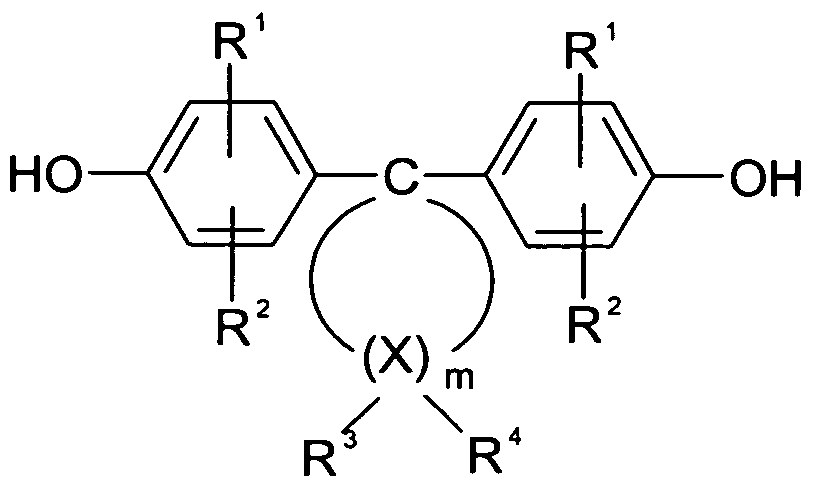
(Ia)(Ia)
Außerdem können die Diphenole der Formel (Ia) auch im Gemisch mit anderen Diphenolen, beispielsweise mit denen der Formel (Ib)In addition, the diphenols of the formula (Ia) may also be mixed with other diphenols, for example with those of the formula (Ib)
HO - Z - OH (Ib),HO - Z - OH (Ib),
zur Herstellung von hochmolekularen, thermoplastischen, aromatischen Polycarbonatderivaten verwendet werden.be used for the preparation of high molecular weight, thermoplastic, aromatic polycarbonate derivatives.
Geeignete andere Diphenole der Formel (Ib) sind solche, in denen Z ein aromatischer Rest mit 6 bis 30 C-Atomen ist, der einen oder mehrere aromatische Kerne enthalten kann, substituiert sein kann und aliphatische Reste oder andere cycloaliphatische Reste als die der Formel (Ia) oder Heteroatome als Brückenglieder enthalten kann. Beispiele der Diphenole der Formel (Ib) sind Hydrochinon, Resorcin, Dihydroxydiphenyle, Bi- (hydroxyphenyl)-alkane, Bis-(hydroxyphenyl)-cycloalkane, Bis-(hydroxyphenyl)-sulfide, Bis-(hydroxyphenyl)-ether, Bis-(hydroxyphenyl)-ketone, Bis-(hydroxyphenyl)-sulfone, Bis- (hydroxyphenyl)-sulfoxide, alpha, alpha'-Bis-(hydroxyphenyl)-diisopropylbenzole sowie deren kernalkylierte und kernhalogenierte Verbindungen. Diese und weitere geeignete Diphenole sind beispielsweise in US 3 028 365 A, 2 999 835 A, 3 148 172 A, 3 275 601 A1 2 991 273 A, 3 271 367 A, 3 062 781 A, 2 970 131 A und US 2 999 846 A, in DE 1 570 703 A, 2 063 050 A, 2 063 052 A, 2 211 956 A, FR 1 561 518 A und in H. Schnell in: Chemistry and Physics of Polycarbonates, Interscience Publishers, New York 1964, beschrieben, welche hiermit vollumfänglich in den Offenbarungsgehalt der vorliegenden Anmeldung aufgenommen werden. Bevorzugte andere Diphenole sind beispielsweise: 4,4'-Dihydroxydiphenyl, 2,2-Bis-(4-hydroxyphenyl)-propan, 2,4-Bis-(4- hydroxyphenyl)-2-methylbutan, 1 ,1-Bis-(4-hydroxyphenyl)-cyclohexan, alpha, alpha-Bis- (4-hydroxyphenyl)-p-diisopropylbenzol, 2,2-Bis-(3-methyl-4-hydroxyphenyl)-propan, 2,2-
Bis-(3-chlor-4-hydroxyphenyl)-propan, Bis-(3,5-dimethyl-4-hydroxyphenyl)-methan, 2,2- Bis-(3,5-dimethyl-4-hydroxyphenyl)-propan, Bis-(3,5-dimethyl-4-hydroxyphenyl)-sulfon, 2,4-Bis-(3,5-dimethyl-4-hydroxyphenyl)-2-methylbutan, 1 ,1-Bis-(3,5-dimethyl-4- hydroxyphenyl)-cyclohexan, alpha, alpha-Bis-(3,5-dimethyl-4-hydroxyphenyl)-p- diisopropylbenzol, 2,2-Bis-(3,5-dichlor-4-hydroxyphenyl)-propan und 2,2-Bis-(3,5-dibrom- 4-hydroxyphenyl)-propan. Besonders bevorzugte Diphenole der Formel (Ib) sind beispielsweise 2,2-Bis-(4-hydroxyphenyl)-propan, 2,2-Bis-(3,5-dimethyl-4-hydroxyphenyl)- propan, 2,2-Bis-(3,5-dichlor-4-hydroxyphenyl)-propan, 2,2-Bis-(3,5-dibrom-4- hydroxyphenyl)-propan und 1 ,1-Bis-(4-hydroxyphenyl)-cyclohexan. Insbesondere ist 2,2- Bis-(4-hydroxyphenyl)-propan bevorzugt. Die anderen Diphenole können sowohl einzeln als auch im Gemisch eingesetzt werden. Das molare Verhältnis von Diphenolen der Formel (Ia) zu den gegebenenfalls mit zu verwendenden anderen Diphenolen der Formel (Ib), soll zwischen 100 Mol-% (Ia) zu 0 Mol-% (Ib) und 2 Mol-% (Ia) zu 98 Mol-% (Ib), vorzugsweise zwischen 100 Mol-% (Ia) zu 0 Mol-% (Ib) und 10 Mol-% (Ia) zu 90 Mol-% (Ib) und insbesondere zwischen 100 Mol-% (Ia) zu 0 Mol-% (Ib) und 30 Mol-% (Ia) zu 70 Mol-% (Ib) liegen. Die hochmolekularen Polycarbonatderivate aus den Diphenolen der Formel (Ia), gegebenenfalls in Kombination mit anderen Diphenolen, können nach den bekannten Polycarbonat-Herstellungsverfahren hergestellt werden. Dabei können die verschiedenen Diphenole sowohl statistisch als auch blockweise miteinander verknüpft sein. Die eingesetzten Polycarbonatderivate können in an sich bekannter Weise verzweigt sein. Wenn die Verzweigung gewünscht wird, kann diese in bekannter Weise durch Einkondensieren geringer Mengen, vorzugsweise Mengen von 0,05 bis 2,0 Mol-% (bezogen auf eingesetzte Diphenole), an drei- oder mehr als dreifunktionellen Verbindungen, insbesondere solchen mit drei oder mehr als drei phenolischen Hydroxylgruppen, erreicht werden. Einige Verzweiger mit drei oder mehr als drei phenolischen Hydroxylgruppen sind Phloroglucin, 4,6-Dimethyl-2,4,6-tri-(4- hydroxyphenyl)-hepten-2,4,6-Dimethyl-2,4,6-tri-(4-hydroxyphenyl)-heptan, 1 ,3,5-Tri-(4- hydroxyphenyl)-benzol, 1 ,1 ,1-Tri-(4-hydroxyphenyl)-ethan, Tri-(4-hydroxyphenyl)- phenylmethan, 2,2-Bis-[4,4-bis-(4-hydroxyphenyl)-cyclohexyl]-propan, 2,4-Bis-(4- hydroxyphenyl-isopropyl)-phenol, 2,6-Bis-(2-hydroxy-5-methyl-benzyl)-4-methylphenol, 2- (4-hydroxyphenyl)-2-(2,4-dihydroxyphenyl)-propan, Hexa-[4-(4-hydroxyphenyl-isopropyl)- phenyl]-orthoterephthalsäureester, Tetra-(4-hydroxyphenyl)-methan, Tetra-[4-(4- hydroxyphenyl-isopropyl)phenoxy]-methan und 1 ,4-Bis-[4',4"-dihydroxytriphenyl)-methyl]- benzol. Einige der sonstigen dreifunktionellen Verbindungen sind 2,4- Dihydroxybenzoesäure, Trimesinsäure, Cyanurchlorid und 3,3-Bis-(3-methyl-4-
hydroxyphenyl)-2-oxo-2,3-dihydroindol. Als Kettenabbrecher zur an sich bekannten Regelung des Molekulargewichts der Polycarbonatderivate dienen monofunktionelle Verbindungen in üblichen Konzentraten. Geeignete Verbindungen sind z.B. Phenol, tert. Butylphenole oder andere Alkyl-substituierte Phenole. Zur Regelung des Molekulargewichts sind insbesondere kleine Mengen Phenole der Formel (Ic) geeignetSuitable other diphenols of the formula (Ib) are those in which Z is an aromatic radical having 6 to 30 C atoms, which may contain one or more aromatic nuclei, may be substituted, and aliphatic radicals or cycloaliphatic radicals other than those of the formula (II) Ia) or heteroatoms may contain as bridge members. Examples of the diphenols of the formula (Ib) are hydroquinone, resorcinol, dihydroxydiphenyls, bis (hydroxyphenyl) alkanes, bis (hydroxyphenyl) cycloalkanes, bis (hydroxyphenyl) sulfides, bis (hydroxyphenyl) ether, bis ( hydroxyphenyl) ketones, bis (hydroxyphenyl) sulfones, bis (hydroxyphenyl) sulfoxides, alpha, alpha'-bis (hydroxyphenyl) diisopropylbenzenes, and their nuclear alkylated and nuclear halogenated compounds. These and other suitable diphenols are described, for example, in US 3,028,365 A, 2,999,835 A, 3,148,172 A, 3,275,601 A 1 2,991,273 A, 3,271,367 A, 3,062,781 A, 2,970,131 A, and US 2,999,846 A, in DE 1 570 703 A, 2 063 050 A, 2 063 052 A, 2 211 956 A, FR 1 561 518 A and in H. Schnell in: Chemistry and Physics of Polycarbonates, Interscience Publishers, New York 1964, which are hereby incorporated in full in the disclosure of the present application. Preferred other diphenols are, for example: 4,4'-dihydroxydiphenyl, 2,2-bis (4-hydroxyphenyl) propane, 2,4-bis (4-hydroxyphenyl) -2-methylbutane, 1, 1-bis ( 4-hydroxyphenyl) cyclohexane, alpha, alpha-bis (4-hydroxyphenyl) -p-diisopropylbenzene, 2,2-bis (3-methyl-4-hydroxyphenyl) -propane, 2,2- Bis- (3-chloro-4-hydroxyphenyl) -propane, bis (3,5-dimethyl-4-hydroxyphenyl) -methane, 2,2-bis- (3,5-dimethyl-4-hydroxyphenyl) -propane, Bis (3,5-dimethyl-4-hydroxyphenyl) sulfone, 2,4-bis (3,5-dimethyl-4-hydroxyphenyl) -2-methylbutane, 1,1-bis- (3,5-dimethyl 4-hydroxyphenyl) cyclohexane, alpha, alpha-bis (3,5-dimethyl-4-hydroxyphenyl) -p-diisopropylbenzene, 2,2-bis (3,5-dichloro-4-hydroxyphenyl) -propane and 2,2-bis- (3,5-dibromo-4-hydroxyphenyl) -propane. Particularly preferred diphenols of the formula (Ib) are, for example, 2,2-bis (4-hydroxyphenyl) propane, 2,2-bis (3,5-dimethyl-4-hydroxyphenyl) propane, 2,2-bis- (3,5-dichloro-4-hydroxyphenyl) -propane, 2,2-bis (3,5-dibromo-4-hydroxyphenyl) -propane and 1, 1-bis (4-hydroxyphenyl) -cyclohexane. In particular, 2,2-bis (4-hydroxyphenyl) propane is preferred. The other diphenols can be used both individually and in a mixture. The molar ratio of diphenols of the formula (Ia) to the other diphenols of the formula (Ib) which may optionally be used should be between 100 mol% (Ia) to 0 mol% (Ib) and 2 mol% (Ia) 98 mol% (Ib), preferably between 100 mol% (Ia) to 0 mol% (Ib) and 10 mol% (Ia) to 90 mol% (Ib) and in particular between 100 mol% (Ia ) to 0 mol% (Ib) and 30 mol% (Ia) to 70 mol% (Ib). The high molecular weight polycarbonate derivatives from the diphenols of the formula (Ia), optionally in combination with other diphenols, can be prepared by the known polycarbonate production processes. The various diphenols can be linked together both statistically and in blocks. The polycarbonate derivatives used can be branched in a manner known per se. If the branching is desired, this can in known manner by condensing small amounts, preferably amounts of 0.05 to 2.0 mol% (based on diphenols), of trifunctional or more than trifunctional compounds, in particular those with three or more than three phenolic hydroxyl groups can be achieved. Some branching agents having three or more than three phenolic hydroxyl groups are phloroglucinol, 4,6-dimethyl-2,4,6-tri- (4-hydroxyphenyl) -heptene-2,4,6-dimethyl-2,4,6-tri - (4-hydroxyphenyl) heptane, 1, 3,5-tri (4-hydroxyphenyl) benzene, 1,1,1-tri (4-hydroxyphenyl) ethane, tri- (4-hydroxyphenyl) phenylmethane , 2,2-bis [4,4-bis (4-hydroxyphenyl) cyclohexyl] propane, 2,4-bis (4-hydroxyphenyl-isopropyl) -phenol, 2,6-bis (2-bis) hydroxy-5-methylbenzyl) -4-methylphenol, 2- (4-hydroxyphenyl) -2- (2,4-dihydroxyphenyl) -propane, hexa- [4- (4-hydroxyphenyl-isopropyl) -phenyl] -orthoterephthalic acid ester , Tetra (4-hydroxyphenyl) methane, tetra- [4- (4-hydroxyphenyl-isopropyl) -phenoxy] -methane and 1,4-bis- [4 ', 4 "-dihydroxytriphenyl) -methyl] -benzene the other trifunctional compounds are 2,4-dihydroxybenzoic acid, trimesic acid, cyanuric chloride and 3,3-bis- (3-methyl-4-) hydroxyphenyl) -2-oxo-2,3-dihydroindole. As chain terminators known per se regulation of the molecular weight of the polycarbonate derivatives are monofunctional compounds in conventional concentrates. Suitable compounds include phenol, tert. Butylphenols or other alkyl-substituted phenols. For controlling the molecular weight, in particular small amounts of phenols of the formula (Ic) are suitable

(Ic)(Ic)
worin R einen verzweigten C8- und/oder C9-Alkylrest darstellt. Bevorzugt ist im Alkylrest R der Anteil an CH3-Protonen zwischen 47 und 89 % und der Anteil der CH- und CH2- Protonen zwischen 53 und 11 %; ebenfalls bevorzugt ist R in o- und/oder p-Stellung zur OH-Gruppe, und besonders bevorzugt die obere Grenze des ortho-Anteils 20 %. Die Kettenabbrecher werden im allgemeinen in Mengen von 0,5 bis 10, bevorzugt 1 ,5 bis 8 Mol-%, bezogen auf eingesetzte Diphenole, eingesetzt. Die Polycarbonatderivate können vorzugsweise nach dem Phasengrenzflächenverhalten (vgl. H. Schnell in. Chemistry and Physics of Polycarbonates, Polymer Reviews, Vol. IX, Seite 33ff., Interscience Publ. 1964) in an sich bekannter Weise hergestellt werden. Hierbei werden die Diphenole der Formel (Ia) in wässrig alkalischer Phase gelöst. Zur Herstellung von Copolycarbonaten mit anderen Diphenolen werden Gemische von Diphenolen der Formel (Ia) und den anderen Diphenolen, beispielsweise denen der Formel (Ib), eingesetzt. Zur Regulierung des Molekulargewichts können Kettenabbrecher z.B. der Formel (Ic) zugegeben werden. Dann wird in Gegenwart einer inerten, vorzugsweise Polycarbonat lösenden, organischen Phase mit Phosgen nach der Methode der Phasengrenzflächenkondensation umgesetzt. Die Reaktionstemperatur liegt im Bereich von 00C bis 400C. Die gegebenenfalls mit verwendeten Verzweiger (bevorzugt 0,05 bis 2,0 Mol-%) können entweder mit den Diphenolen in der wässrig alkalischen Phase vorgelegt werden oder in dem organischen Lösungsmittel gelöst vor Phosgenierung zugegeben werden. Neben den Diphenolen der Formel (Ia) und gegebenenfalls anderen Diphenolen (Ib) können auch deren Mono- und/oder Bis-chlorkohlensäureester mit verwendet werden, wobei diese in organischen Lösungsmitteln gelöst zugegeben werden. Die Menge an Kettenabbrechern sowie an Verzweigern richtet sich dann nach der molaren Menge von Diphenolat-Resten
entsprechend Formel (Ia) und gegebenenfalls Formel (Ib); bei Mitverwendung von Chlorkohlensäureestern kann die Phosgenmenge in bekannter Weise entsprechend reduziert werden. Geeignete organische Lösungsmittel für die Kettenabbrecher sowie gegebenenfalls für die Verzweiger und die Chlorkohlensäureester sind beispielsweise Methylenchlorid, Chlorbenzol sowie insbesondere Mischungen aus Methylenchlorid und Chlorbenzol. Gegebenenfalls können die verwendeten Kettenabbrecher und Verzweiger im gleichen Solvens gelöst werden. Als organische Phase für die Phasengrenzflächenpolykondensation dienen beispielsweise Methylenchlorid, Chlorbenzol sowie Mischungen aus Methylenchlorid und Chlorbenzol. Als wässrige alkalische Phase dient beispielsweise NaOH-Lösung. Die Herstellung der Polycarbonatderivate nach dem Phasengrenzflächenverfahren kann in üblicher Weise durch Katalysatoren wie tertiäre Amine, insbesondere tertiäre aliphatische Amine wie Tributylamin oder Triethylamin katalysiert werden; die Katalysatoren können in Mengen von 0,05 bis 10 Mol-%, bezogen auf Mole an eingesetzten Diphenolen, eingesetzt werden. Die Katalysatoren können vor Beginn der Phosgenierung oder während oder auch nach der Phosgenierung zugesetzt werden. Die Polycarbonatderivate können nach dem bekannten Verfahren in homogener Phase, dem sogenannten "Pyridinverfahren" sowie nach dem bekannten Schmelzeumesterungsverfahren unter Verwendung von beispielsweise Diphenylcarbonat anstelle von Phosgen hergestellt werden. Die Polycarbonatderivate können linear oder verzweigt sein, sie sind Homopolycarbonate oder Copolycarbonate auf Basis der Diphenole der Formel (Ia). Durch die beliebige Komposition mit anderen Diphenolen, insbesondere mit denen der Formel (Ib) lassen sich die Polycarbonateigenschaften in günstiger Weise variieren. In solchen Copolycarbonaten sind die Diphenole der Formel (Ia) in Mengen von 100 Mol-% bis 2 Mol-%, vorzugsweise in Mengen von 100 Mol-% bis 10 Mol-% und insbesondere in Mengen von 100 Mol-% bis 30 Mol-%, bezogen auf die Gesamtmenge von 100 Mol-% an Diphenoleinheiten, in Polycarbonatderivaten enthalten. Das Polycarbonatderivat kann ein Copolymer sein, enthaltend, insbesondere hieraus bestehend, Monomereinheiten M1 auf Basis der Formel (lb),vorzugsweise Bisphenol A, sowie Monomereinheiten M2 auf Basis des geminal disubstituierten Dihydroxydiphenylcycloalkans, vorzugsweise des 4,4'-(3,3,5- trimethylcyclohexan-1 ,1-diyl)diphenols, wobei das Molverhältnis M2/M1 vorzugsweise größer als 0,3, insbesondere größer als 0,4, beispielsweise größer als 0,5 ist. Bevorzugt ist es, wenn das Polycarbonatderivat ein mittleres Molekulargewicht (Gewichtsmittel) von mindestens 10.000, vorzugsweise von 20.000 bis 300.000, aufweist. Die Komponente B kann grundsätzlich im Wesentlichen organisch oder wässrig sein. Im Wesentlichen
wässrig bedeutet dabei, dass bis zu 20 Gew.-% der Komponente B) organische Lösungsmittel sein können. Im Wesentlichen organisch bedeutet, dass bis zu 5 Gew.-% Wasser in der Komponente B) vorliegen können. Vorzugsweise enthält die Komponente B einen bzw. besteht aus einem flüssigen aliphatischen, cycloaliphatischen und/oder aromatischen Kohlenwasserstoff, einem flüssigen organischen Ester und/oder einer Mischung solcher Substanzen. Die eingesetzten organischen Lösungsmittel sind vorzugsweise halogenfreie organische Lösungsmittel. In Frage kommen insbesondere aliphatische, cycloaliphatische, aromatische Kohlenwasserstoffe, wie Mesitylen, 1 ,2,4- Trimethylbenzol, Cumol und Solvent Naptha, Toluol, XyIoI; (organische) Ester, wie Methylacetat, Ethylacetat, Butylacetat, Methoxypropylacetat, Ethyl-3-ethoxypropionat. Bevorzugt sind Mesitylen, 1 ,2,4-Trimethylbenzol, Cumol und Solvent Naptha, Toluol, XyIoI, Essigsäuremethylester, Essigsäureethylester, Methoxypropylacetat. Ethyl-3- ethoxypropionat. Ganz besonders bevorzugt sind Mesitylen (1 ,3,5-Trimethylbenzol), 1 ,2,4-Trimethylbenzol, Cumol (2-Phenylpropan), Solvent Naptha und Ethyl-3- ethoxypropionat. Ein geeignetes Lösungsmittelgemisch umfasst beispielsweise L1 ) 0 bis 10 Gew.-%, vorzugsweise 1 bis 5 Gew.-%, insbesondere 2 bis 3 Gew.-%, Mesitylen, L2) 10 bis 50 Gew.-%, vorzugsweise 25 bis 50 Gew.-%, insbesondere 30 bis 40 Gew.-%, 1- Methoxy-2-propanolacetat, L3) 0 bis 20 Gew.-%, vorzugsweise 1 bis 20 Gew.-%, insbesondere 7 bis 15 Gew.-%, 1 ,2,4-Trimethylbenzol, L4) 10 bis 50 Gew.-%, vorzugsweise 25 bis 50 Gew.-%, insbesondere 30 bis 40 Gew.-%, Ethyl-3- ethoxypropionat, L5) 0 bis 10 Gew.-%, vorzugsweise 0,01 bis 2 Gew.-%, insbesondere 0,05 bis 0,5 Gew.-%, Cumol, und L6) 0 bis 80 Gew.-%, vorzugsweise 1 bis 40 Gew.-%, insbesondere 15 bis 25 Gew.-%, Solvent Naphtha, wobei die Summe der Komponenten L1 bis L6 stets 100 Gew.-% ergibt. Die Zubereitung kann im Detail enthalten: A) 0,1 bis 10 Gew.-%, insbesondere 0,5 bis 5 Gew.-%, eines Bindemittels mit einem Polycarbonatderivat auf Basis eines geminal disubstituiertenwherein R represents a branched C 8 and / or C 9 alkyl radical. Preferably, in the alkyl radical R, the proportion of CH 3 protons between 47 and 89% and the proportion of CH and CH 2 - protons between 53 and 11%; also preferably R is in the o- and / or p-position to the OH group, and more preferably the upper limit of the ortho-portion is 20%. The chain terminators are generally used in amounts of 0.5 to 10, preferably 1, 5 to 8 mol%, based on diphenols used. The polycarbonate derivatives can preferably be prepared in a manner known per se according to the phase interface behavior (compare H. Schnell in. Chemistry and Physics of Polycarbonates, Polymer Reviews, Vol. IX, page 33 et seq., Interscience Publ. In this case, the diphenols of the formula (Ia) are dissolved in an aqueous alkaline phase. For the preparation of copolycarbonates with other diphenols, mixtures of diphenols of the formula (Ia) and the other diphenols, for example those of the formula (Ib), are used. To regulate the molecular weight, chain terminators of, for example, the formula (Ic) can be added. Then, in the presence of an inert, preferably polycarbonate-dissolving, organic phase is reacted with phosgene by the method of interfacial condensation. The reaction temperature is in the range from 0 ° C. to 40 ° C. The branching agents which may be used (preferably 0.05 to 2.0 mol%) may be initially charged with the diphenols in the aqueous alkaline phase or dissolved in the organic solvent be added before phosgenation. In addition to the diphenols of the formula (Ia) and, if appropriate, other diphenols (Ib), their mono- and / or bis-chlorocarbonic acid esters may also be used, these being added dissolved in organic solvents. The amount of chain terminators and branching agents then depends on the molar amount of diphenolate residues corresponding to formula (Ia) and optionally formula (Ib); When using chloroformates the amount of phosgene can be reduced accordingly in a known manner. Suitable organic solvents for the chain terminators and optionally for the branching agents and the chloroformates are, for example, methylene chloride, chlorobenzene and in particular mixtures of methylene chloride and chlorobenzene. Optionally, the chain terminators and branching agents used can be dissolved in the same solvent. For example, methylene chloride, chlorobenzene and mixtures of methylene chloride and chlorobenzene serve as the organic phase for the interfacial polycondensation. The aqueous alkaline phase used is, for example, NaOH solution. The preparation of the polycarbonate derivatives by the interfacial process can be catalyzed in a conventional manner by catalysts such as tertiary amines, in particular tertiary aliphatic amines such as tributylamine or triethylamine; the catalysts can be used in amounts of 0.05 to 10 mol%, based on moles of diphenols used. The catalysts can be added before the beginning of the phosgenation or during or after the phosgenation. The polycarbonate derivatives can be prepared by the known method in the homogeneous phase, the so-called "pyridine process" and by the known melt transesterification process using, for example, diphenyl carbonate instead of phosgene. The polycarbonate derivatives may be linear or branched, they are homopolycarbonates or copolycarbonates based on the diphenols of the formula (Ia). By arbitrary composition with other diphenols, in particular with those of the formula (Ib), the polycarbonate properties can be varied in a favorable manner. In such copolycarbonates, the diphenols of the formula (Ia) are present in amounts of from 100 mol% to 2 mol%, preferably in amounts of from 100 mol% to 10 mol% and in particular in amounts of from 100 mol% to 30 mol% %, based on the total amount of 100 mol% of diphenol units contained in polycarbonate derivatives. The polycarbonate derivative may be a copolymer containing, in particular consisting thereof, monomer units M1 based on the formula (Ib), preferably bisphenol A, and monomer units M2 based on the geminally disubstituted dihydroxydiphenylcycloalkane, preferably the 4,4 ' - (3,3,5 - Trimethylcyclohexan-1, 1-diyl) diphenols, wherein the molar ratio M2 / M1 is preferably greater than 0.3, in particular greater than 0.4, for example greater than 0.5. It is preferred that the polycarbonate derivative has a weight average molecular weight of at least 10,000, preferably from 20,000 to 300,000. In principle, component B may be substantially organic or aqueous. Essentially aqueous means that up to 20% by weight of component B) can be organic solvents. Substantially organic means that up to 5% by weight of water may be present in component B). Component B preferably contains one or consists of a liquid aliphatic, cycloaliphatic and / or aromatic hydrocarbon, a liquid organic ester and / or a mixture of such substances. The organic solvents used are preferably halogen-free organic solvents. Particularly suitable are aliphatic, cycloaliphatic, aromatic hydrocarbons, such as mesitylene, 1, 2,4-trimethylbenzene, cumene and solvent naphtha, toluene, xylene; (organic) esters such as methyl acetate, ethyl acetate, butyl acetate, methoxypropyl acetate, ethyl 3-ethoxypropionate. Preference is given to mesitylene, 1, 2,4-trimethylbenzene, cumene and solvent naphtha, toluene, xylene, methyl acetate, ethyl acetate, methoxypropyl acetate. Ethyl 3-ethoxypropionate. Most particularly preferred are mesitylene (1, 3,5-trimethylbenzene), 1, 2,4-trimethylbenzene, cumene (2-phenylpropane), solvent naphtha and ethyl 3-ethoxypropionate. A suitable solvent mixture comprises, for example, L1) 0 to 10% by weight, preferably 1 to 5% by weight, in particular 2 to 3% by weight, mesitylene, L2) 10 to 50% by weight, preferably 25 to 50% by weight %, in particular 30 to 40 wt.%, 1-methoxy-2-propanol acetate, L3) 0 to 20 wt.%, preferably 1 to 20 wt.%, in particular 7 to 15 wt.%, 1 , 2,4-trimethylbenzene, L4) 10 to 50 wt.%, Preferably 25 to 50 wt.%, In particular 30 to 40 wt.%, Ethyl 3-ethoxypropionate, L5) 0 to 10 wt. , preferably 0.01 to 2 wt .-%, in particular 0.05 to 0.5 wt .-%, cumene, and L6) 0 to 80 wt .-%, preferably 1 to 40 wt .-%, in particular 15 to 25 wt .-%, solvent naphtha, wherein the sum of components L1 to L6 always gives 100 wt .-%. The preparation may contain in detail: A) 0.1 to 10 wt .-%, in particular 0.5 to 5 wt .-%, of a binder with a polycarbonate derivative based geminal disubstituted
Dihydroxydiphenylcycloalkans, B) 40 bis 99,9 Gew.-%, insbesondere 45 bis 99,5 Gew.-%, eines organischen Lösungsmittels oder Lösungsmittelgemischs, C) 0,1 bis 6 Gew.-%, insbesondere 0,5 bis 4 Gew.-%, eines Farbmittels oder Farbmittelgemischs, D) 0,001 bis 6 Gew.-%, insbesondere 0,1 bis 4 Gew.-%, eines funktionales Materials oder einer Mischung funktionaler Materialien, E) 0,1 bis 30 Gew.-%, insbesondere 1 bis 20 Gew.-%, Additive und/oder Hilfsstoffe, oder eine Mischung solcher Stoffe. Als Komponente C, sofern ein Farbmittel vorgesehen sein soll, kommt grundsätzlich jedes beliebige Farbmittel oder Farbmittelgemisch in Frage. Unter Farbmittel sind alle farbgebenden Stoffe bezeichnet. Das bedeutet, es kann sich sowohl um Farbstoffe (einen Überblick über
Farbstoffe gibt Ullmann's Encyclopedia of Industrial Chemistry, Electronic Release 2007, Wiley Verlag, Kapitel „Dyes, General Survey") wie auch um Pigmente (einen Überblick über organische wie anorganische Pigmente gibt Ullmann's Encyclopedia of Industrial Chemistry, Electronic Release 2007, Wiley Verlag, Kapitel „Pigments, Organic" bzw. "Pigments, Inorganic") handeln. Farbstoffe sollten in den Lösungsmitteln der Komponente B löslich bzw. (stabil) dispergierbar oder suspendierbar sein. Des Weiteren ist es vorteilhaft, wenn das Farbmittel bei Temperaturen von 1600C und mehr für einen Zeitraum von mehr als 5 min. stabil, insbesondere farbstabil ist. Es ist auch möglich, dass das Farbmittel einer vorgegebenen und reproduzierbaren Farbveränderung unter den Verarbeitungsbedingungen unterworfen ist und entsprechend ausgewählt wird. Pigmente müssen neben der Temperaturstabilität insbesondere in feinster Partikelgrößenverteilung vorliegen. Für einen Tintenstrahldruck bedeutet dies in der Praxis, dass die Teilchengröße nicht über 1 ,0 μm hinausgehen sollte, da sonst Verstopfungen im Druckkopf die Folge sind. In der Regel haben sich nanoskalige Festkörperpigmente und gelöste Farbstoffe bewährt. Die Farbmittel können kationisch, anionisch oder auch neutral sein. Lediglich als Beispiele für im Tintenstrahldruck verwendbare Farbmittel seinen genannt: Brillantschwarz Cl. Nr. 28440, Chromogenschwarz Cl. Nr. 14645, Direkttiefschwarz E Cl. Nr. 30235, Echtschwarzsalz B Cl. Nr. 37245, Echtschwarzsalz K Cl. Nr. 37190, Sudanschwarz HB Cl. 26150, Naphtolschwarz Cl. Nr. 20470, Bayscript® Schwarz flüssig, Cl. Basic Black 11 , Cl. Basic Blue 154, Cartasol® Türkis K-ZL flüssig, Cartasol® Türkis K-RL flüssig (Cl. Basic Blue 140), Cartasol Blau K5R flüssig. Geeignet sind des Weiteren z.B. die im Handel erhältlichen Farbstoffe Hostafine® Schwarz TS flüssig (vertrieben von Clariant GmbH Deutschland),Dihydroxydiphenylcycloalkanes, B) 40 to 99.9% by weight, in particular 45 to 99.5% by weight, of an organic solvent or solvent mixture, C) 0.1 to 6% by weight, in particular 0.5 to 4% by weight D) 0.001 to 6 wt .-%, in particular 0.1 to 4 wt .-%, of a functional material or a mixture of functional materials, E) 0.1 to 30 wt .-% , in particular 1 to 20 wt .-%, additives and / or auxiliaries, or a mixture of such substances. As component C, if a colorant is to be provided, basically any colorant or colorant mixture comes into question. Colorants are all colorants. That means it can be both colorant (an overview of Dyes are Ullmann's Encyclopedia of Industrial Chemistry, Electronic Release 2007, Wiley Publishing, Chapter "Dyes, General Survey") as well as pigments (for an overview of organic and inorganic pigments, see Ullmann's Encyclopedia of Industrial Chemistry, Electronic Release 2007, Wiley Publishing, chap "Pigments, Organic" or "Pigments, Inorganic") act. Dyes should be soluble or (stably) dispersible or suspendible in the component B solvents. Furthermore, it is advantageous if the colorant at temperatures of 160 0 C and more for a period of more than 5 min. stable, in particular color-stable. It is also possible that the colorant is subjected to a predetermined and reproducible color change under the processing conditions and is selected accordingly. In addition to the temperature stability, pigments must be present in particular in the finest particle size distribution. For inkjet printing, this means in practice that the particle size should not exceed 1, 0 microns, otherwise blockages in the printhead are the result. As a rule, nanoscale solid-state pigments and dissolved dyes have proven their worth. The colorants may be cationic, anionic or even neutral. Just as examples of colorants that can be used in ink-jet printing are called its: Brilliant Black Cl. No. 28440, Chromogen Black Cl. No. 14645, direct deep black E Cl. No. 30235, true black salt B Cl. No. 37245, true black salt K Cl. No. 37190, Sudan Black HB Cl. 26150, Naphtol Black Cl. No. 20470, Bayscript® Black Liquid, Cl. Basic Black 11, Cl. Basic Blue 154, Cartasol® Turquoise K-ZL liquid, Cartasol® Turquoise K-RL liquid (Cl. Basic Blue 140), Cartasol Blue K5R liquid. Also suitable are, for example, the commercially available dyes Hostafine® Black TS liquid (sold by Clariant GmbH Germany),
Bayscript® Schwarz flüssig (C.l.-Gemisch, vertrieben von Bayer AG Deutschland), Cartasol® Schwarz MG flüssig (Cl. Basic Black 11 , Eingetragenes Markenzeichen der Clariant GmbH Deutschland), Flexonylschwarz® PR 100 (E Cl. Nr. 30235, vertrieben von Hoechst AG), Rhodamin B, Cartasol® Orange K3 GL1 Cartasol® Gelb K4 GL, Cartasol® K GL, oder Cartasol® Rot K-3B. Des Weiteren können als lösliche Farbmittel Anthrachinon-, Azo-, Chinophthalon-, Cumarin-, Methin-, Perinon-, und/oder Pyrazolfarbstoffe, z.B. unter dem Markennamen Macrolex® erhältlich, Verwendung finden. Weitere geeignete Farbmittel sind in der Literaturstelle Ullmann's Encyclopedia of Industrial Chemistry, Electronic Release 2008, Wiley Verlag, Kapitel "Colorants Used in Ink Jet Inks" beschrieben. Gut lösliche Farbmittel führen zu einer optimalen Integration in die Matrix bzw. das Bindemittel der Druckschicht. Die Farbmittel können entweder direkt als Farbstoff bzw. Pigment zugesetzt werden oder als Paste, einem Gemisch aus
Farbstoff und Pigment zusammen mit einem weiteren Bindemittel. Dieses zusätzliche Bindemittel sollte chemisch kompatibel mit den weiteren Komponenten der Zubereitung sein. Sofern eine solche Paste als Farbmittel eingesetzt wird, bezieht sich die Mengenangabe der Komponente B auf das Farbmittel ohne die sonstigen Komponenten der Paste. Diese sonstigen Komponenten der Paste sind dann unter die Komponente E zu subsumieren. Bei Verwendung von so genannten Buntpigmenten in den Skalenfarben Cyan-Magenta-Yellow und bevorzugt auch (Ruß)-Schwarz sind Volltonfarbabbildungen möglich. Die Komponente D umfasst Substanzen, die unter Einsatz von technischen Hilfsmitteln unmittelbar durch das menschliche Auge oder durch Verwendung von geeigneten Detektoren ersichtlich sind. Hier sind die dem Fachmann einschlägig bekannten Materialien (vgl. auch van Renesse in: Optica! document security, 3rd Ed., Artech House, 2005) gemeint, die zur Absicherung von Wert und Sicherheitsdokumenten eingesetzt werden. Dazu zählen Lumineszenzstoffe (Farbstoffe oder Pigmente, organisch oder anorganisch) wie z.B. Photoluminophore, Elektroluminophore, Antistokes Luminophore, Fluorophore aber auch magnetisierbare, photoakustisch adressierbare oder piezoelektrische Materialien. Des Weiteren können Raman-aktive oder Raman- verstärkende Materialien eingesetzt werden, ebenso wie so genannte Barcode- Materialien. Auch hier gelten als bevorzugte Kriterien entweder die Löslichkeit in der Komponente B oder bei pigmentierten Systemen Teilchengrößen < 1 μm sowie eine Temperaturstabilität für Temperaturen > 160°C im Sinne der Ausführungen zur Komponente C. Funktionale Materialien können direkt zugegeben werden oder über eine Paste, d.h. einem Gemisch mit einem weiteren Bindemittel, welches dann Bestandteil der Komponente E bildet, oder dem eingesetzten Bindemittel der Komponente A. Die Komponente E umfasst bei Tinten für einen Tintenstrahldruck üblicherweise eingerichtete Stoffe wie Antischaummittel, Stellmittel, Netzmittel, Tenside, Fließmittel, Trockner, Katalysatoren, (Licht-) Stabilisatoren, Konservierungsmittel, Biozide, Tenside, organische Polymere zur Viskositätseinstellung, Puffersysteme, etc. Als Stellmittel kommen fachübliche Stellsalze in Frage. Ein Beispiel hierfür ist Natriumlactat. Als Biozide kommen alle handelsüblichen Konservierungsmittel, welche für Tinten verwendet werden, in Frage. Beispiele hierfür sind ProxelOGXL und Parmetol® A26. Als Tenside kommen alle handelsüblichen Tenside, welche für Tinten verwendet werden, in Frage. Bevorzugt sind amphotere oder nichtionische Tenside. Selbstverständlich ist aber auch der Einsatz spezieller anionischer oder kationischer Tenside, welche die Eigenschaften des Farbstoffs nicht verändern, möglich. Beispiele für geeignete Tenside sind Betaine, ethoxilierte Diole usw. Beispiele sind die Produktreihen Surfynol® und Tergitol®. Die Menge an Tensiden
wird insbesondere bei Anwendung für den Tintenstrahldruck beispielsweise mit der Maßgabe gewählt, dass die Oberflächenspannung der Tinte im Bereich von 10 bis 60 mN/m, vorzugsweise 20 bis 45 mN/m, gemessen bei 25°C, liegt. Es kann ein Puffersystem eingerichtet sein, welches den pH-Wert im Bereich von 2,5 bis 8,5, insbesondere im Bereich von 5 bis 8, stabilisiert. Geeignete Puffersysteme sind Lithiumacetat, Boratpuffer, Triethanolamin oder Essigsäure/Natriumacetat. Ein Puffersystem wird insbesondere im Falle einer im Wesentlichen wässrigen Komponente B in Frage kommen. Zur Einstellung der Viskosität der Tinte können (ggf. wasserlösliche) Polymere vorgesehen sein. Hier kommen alle für übliche Tintenformulierungen geeigneten Polymere in Frage. Beispiele sind wasserlösliche Stärke, insbesondere mit einem mittleren Molekulargewicht von 3.000 bis 7.000, Polyvinylpyrrolidon, insbesondere mit einem mittleren Molekulargewicht von 25.000 bis 250.000, Polyvinylalkohol, insbesondere mit einem mittleren Molekulargewicht von 10.000 bis 20.000, Xanthan- Gummi, Carboxy-Methylcellulose, Ethylenoxid/Propylenoxid-Blockcopolymer, insbesondere mit einem mittleren Molekulargewicht von 1.000 bis 8.000. Ein Beispiel für das letztgenannte Blockcopolymer ist die Produktreihe Pluronic®. Der Anteil an Biozid, bezogen auf die Gesamtmenge an Tinte, kann im Bereich von 0 bis 0,5 Gew-%, vorzugsweise 0,1 bis 0,3 Gew.-%, liegen. Der Anteil an Tensid, bezogen auf die Gesamtmenge an Tinte, kann im Bereich von 0 bis 0,2 Gew.-% liegen. Der Anteil an Stellmitteln kann, bezogen auf die Gesamtmenge an Tinte, 0 bis 1 Gew.-%, vorzugsweise 0,1 bis 0,5 Gew.-%, betragen. Zu den Hilfsmitteln werden auch sonstige Komponenten gezählt, wie beispielsweise Essigsäure, Ameisensäure oder n-Methyl-Pyrolidon oder sonstige Polymere aus der eingesetzten Farbstofflösung oder -Paste. Bezüglich Substanzen, welche als Komponente E geeignet sind, wird ergänzend beispielsweise auf Ullmann's Encyclopedia of Chemical Industry, Electronic Release 2008, Wiley Verlag, Kapitel „Paints and Coatings", Sektion „Paint Additives", verwiesen. Ferner werden die Materialien, die einen Brechungsindex der Tinte erhöhen zu den Additiven und Hilfsmitteln der Komponente E zugeordnet. Für ein Ausbilden der Lichtleitstruktur werden Tinten bevorzugt, die keine Pigmente größer als 250 nm als Farbmittel enthalten, da diese als Streuzentren eine Lichtleitung negativ beeinflussen.Bayscript® Black Liquid (Cl mixture, sold by Bayer AG Germany), Cartasol® Black MG liquid (Cl., Basic Black 11, Registered Trade Mark of Clariant GmbH Germany), Flexonyl Black® PR 100 (E Cl., No. 30235, marketed by Hoechst AG), Rhodamine B, Cartasol® Orange K3 GL 1 Cartasol® Yellow K4 GL, Cartasol® K GL, or Cartasol® Red K-3B. Furthermore, anthraquinone, azo, quinophthalone, coumarin, methine, perinone, and / or pyrazole dyes, eg available under the trade name Macrolex®, can be used as soluble colorants. Further suitable colorants are described in the reference Ullmann 's Encyclopedia of Industrial Chemistry, Electronic Release 2008, Wiley Verlag, chapter "Colorants Used in Ink Jet Inks". Well-soluble colorants lead to an optimal integration into the matrix or the binder of the print layer. The colorants can be added either directly as a dye or pigment or as a paste, a mixture of Dye and pigment together with another binder. This additional binder should be chemically compatible with the other components of the formulation. If such a paste is used as a colorant, the amount of component B refers to the colorant without the other components of the paste. These other components of the paste are then subsumed under the component E. When using so-called colored pigments in the scale colors cyan-magenta-yellow and preferably also (soot) black solid color images are possible. Component D comprises substances that can be seen directly by the human eye or by the use of suitable detectors using technical aids. Here are the materials known to those skilled in the art (see also van Renesse in: Optica !, document security, 3rd ed., Artech House, 2005), which are used to secure value and security documents. These include luminescent substances (dyes or pigments, organic or inorganic) such as photoluminophores, electroluminophores, Antistokes luminophores, fluorophores but also magnetizable, photoacoustically addressable or piezoelectric materials. Furthermore, Raman-active or Raman-reinforcing materials can be used, as well as so-called barcode materials. Again, the preferred criteria are either the solubility in the component B or pigmented systems particle sizes <1 micron and a temperature stability for temperatures> 160 ° C in the sense of the comments on the component C. Functional materials can be added directly or via a paste, ie a mixture with a further binder, which then forms part of component E, or the binder of component A. The component E comprises inks for inkjet printing usually furnished substances such as anti-foaming agents, adjusting agents, wetting agents, surfactants, flow agents, dryers, catalysts, (Light) stabilizers, preservatives, biocides, surfactants, organic polymers for viscosity adjustment, buffer systems, etc. Suitable adjusting agents are commercially available actuating salts in question. An example of this is sodium lactate. As biocides, all commercially available preservatives which are used for inks come into question. Examples are ProxelOGXL and Parmetol® A26. Suitable surfactants are all commercially available surfactants which are used for inks. Preferred are amphoteric or nonionic surfactants. Of course, it is also possible to use special anionic or cationic surfactants which do not alter the properties of the dye. Examples of suitable surfactants are betaines, ethoxylated diols, etc. Examples are the product series Surfynol® and Tergitol®. The amount of surfactants For example, it is selected, for example, when used for ink-jet printing, with the proviso that the surface tension of the ink is in the range of 10 to 60 mN / m, preferably 20 to 45 mN / m, measured at 25 ° C. A buffer system can be set up which stabilizes the pH in the range from 2.5 to 8.5, in particular in the range from 5 to 8. Suitable buffer systems are lithium acetate, borate buffer, triethanolamine or acetic acid / sodium acetate. A buffer system will be considered in particular in the case of a substantially aqueous component B. To adjust the viscosity of the ink (possibly water-soluble) polymers can be provided. Here all suitable for conventional ink formulations polymers come into question. Examples are water-soluble starch, in particular with an average molecular weight of 3,000 to 7,000, polyvinylpyrrolidone, in particular with an average molecular weight of 25,000 to 250,000, polyvinyl alcohol, in particular with an average molecular weight of 10,000 to 20,000, xanthan gum, carboxymethylcellulose, ethylene oxide / propylene oxide Block copolymer, especially having an average molecular weight of 1,000 to 8,000. An example of the latter block copolymer is the product series Pluronic®. The proportion of biocide, based on the total amount of ink, may be in the range of 0 to 0.5% by weight, preferably 0.1 to 0.3% by weight. The proportion of surfactant, based on the total amount of ink, can range from 0 to 0.2 wt .-%. The proportion of adjusting agents, based on the total amount of ink, 0 to 1 wt .-%, preferably 0.1 to 0.5 wt .-%, amount. The auxiliaries also include other components, such as, for example, acetic acid, formic acid or n-methylpyrolidone or other polymers from the dye solution or paste used. With regard to substances which are suitable as component E, reference is additionally made, for example, to Ullmann's Encyclopedia of Chemical Industry, Electronic Release 2008, Wiley Verlag, chapter "Paints and Coatings", section "Paint Additives". Further, the materials which increase a refractive index of the ink are assigned to the additives and auxiliaries of the component E. For forming the optical waveguide, inks which do not contain pigments greater than 250 nm as the colorant are preferred since they have a negative effect on light conduction as scattering centers.
Die Merkmale des erfindungsgemäßen Herstellungsverfahrens, des Verfahrens zum Verifizieren sowie der Vorrichtung oder Assistenzvorrichtung zum Verifizieren weisen dieselben Vorteile wie die entsprechenden Merkmale des erfindungsgemäßen Wert- oder Sicherheitsdokuments auf.
Nachfolgend wird die Erfindung anhand bevorzugter Ausführungsbeispiele unter Bezugnahme auf eine Zeichnung näher erläutert. Hierbei zeigen:The features of the manufacturing method according to the invention, of the method for verification and of the device or assistance device for verification have the same advantages as the corresponding features of the value or security document according to the invention. The invention will be explained in more detail with reference to preferred embodiments with reference to a drawing. Hereby show:
Fig. 1 eine schematische Schnittdarstellung durch einen Dokumentenkörper mit einer Lichtleitstruktur;Figure 1 is a schematic sectional view through a document body with a Lichtleitstruktur.
Fig. 2 eine schematische Schnittdarstellung durch den Dokumentenkörper nachFig. 2 is a schematic sectional view through the document body after
Fig. 1 , in den Aussparungen zum Ausbilden von Modifizierungen an einer Grenzschicht der Lichtleitstruktur eingebracht sind;Fig. 1, are incorporated in the recesses for forming modifications to a boundary layer of the light guide structure;
Fig. 3 eine schematische Darstellung eines Dokumentenkörpers nach Fig. 2 zurFig. 3 is a schematic representation of a document body of FIG. 2 for
Erläuterung der Lichtauskopplung an den vorgenommenen Modifizierungen der Grenzschicht der Lichtleitstruktur;Explanation of the light extraction on the modifications made to the boundary layer of the light guide structure;
Fig. 4 eine schematische Darstellung des Dokumentenkörpers nach Fig. 2 und 3 mit einer Assistenzvorrichtung zum Unterstützen der Verifikation des über die Lichtleitstruktur realisierten Sicherheitsmerkmals;4 shows a schematic representation of the document body according to FIGS. 2 and 3 with an assistance device for supporting the verification of the security feature implemented via the lightguide structure;
Fig. 5 eine schematische Schnittdarstellung durch ein Sicherheitsdokument mit einer Lichtleitstruktur, wobei in den Dokumentenkörper eine Lichtquelle integriert ist;5 is a schematic sectional view through a security document with a light guide structure, wherein a light source is integrated in the document body;
Fig. 6 eine schematische Darstellung des Dokumentenkörpers nach Fig. 5, in denFig. 6 is a schematic representation of the document body of FIG. 5, in the
Aussparungen zum Ausbilden von Modifizierungen der Grenzschicht der Lichtleitstruktur eingebracht sind;Recesses for forming modifications of the boundary layer of the light guide structure are introduced;
Fig. 7 eine schematische Darstellung des Dokumentenkörpers nach Fig. 6 zurFig. 7 is a schematic representation of the document body of FIG. 6 for
Erläuterung der Lichtein- und -auskopplung;Explanation of light input and output;
Fig. 8 eine schematische Darstellung eines Substratschichtenstapels;Fig. 8 is a schematic illustration of a substrate layer stack;
Fig. 9 eine schematische Darstellung eines Dokumentenkörpers, der als Laminat aus dem Schichtenstapel nach Fig. 8 hergestellt ist; und
Fig. 10 eine schematische Darstellung zur Erläuterung der Lichtleitein- undFig. 9 is a schematic representation of a document body made as a laminate from the layer stack of Fig. 8; and Fig. 10 is a schematic illustration for explaining the Lichtleitein- and
-auskopplung in dem Dokumentenkörper nach Fig. 9.decoupling in the document body according to FIG. 9.
In Fig. 1 ist schematisch eine Schnittansicht durch ein Wert- oder Sicherheitsdokument 1 dargestellt, welches einen Dokumentenkörper 2 umfasst. Der Dokumentenkörper 2 ist in der dargestellten Ausführungsform ein Laminat. Das Laminat ist aus Substratschichten 3- 9, welches thermoplastische Polymerschichten sind, zu einem Verbundkörper laminiert. Eine oberste Substratschicht 9 und eine unterste Substratschicht 3 sind transparent ausgeführt und dienen als Schutzschichten und werden auch als so genannte Overlay- Schichten bezeichnet. Im Innern des Dokumentenkörpers 2 sind opake Substratschichten 4, 6, 8 angeordnet, die beispielsweise bedruckt sein können. Zwischen den opaken Substratschichten 4, 6, 8 sind transparente Substratschichten 5, 7 angeordnet. Zumindest die zwischen den opaken Substratschichten 6, 8 angeordnete transparente Substratschicht 7 weist in der dargestellten Ausführungsform ein höheren Brechungsindex für Licht im sichtbaren Wellenlängenbereich auf als die beiden angrenzenden opaken Substratschichten 6, 8. Somit bildet die transparente Substratschicht 7 eine Lichtleitstruktur 10. Analog kann auch die Substratschicht 5 eine Lichtleitstruktur sein. Im Folgenden wird ohne eine Beschränkung andeuten zu wollen nur noch auf die Lichtleitstruktur 10 eingegangen. Das für diese Lichtleitstruktur ausgeführte gilt analog für die Substratschicht 5. An einer Seitenkante 11 des Dokumentenkörpers 2 eingekoppeltes Licht 12, welches mittels einer Sinuskurve angedeutet ist, wird über Totalreflexionen an einer oberen Grenzschicht 13 der Lichtleitstruktur 10 und einer unteren Grenzschicht 14 der Lichtleitstruktur 10 zu einer der Seitenkante 11 gegenüberliegenden Seitenkante 15 geleitet. Die obere Grenzschicht 13 zwischen der Lichtleitstruktur 10 und der opaken Substratschicht 8 ist einer Oberseite 16 des Dokumentenkörpers 2 zugewandt. Entsprechend ist die untere Grenzschicht 14 einer Unterseite 17 des Dokumentenkörpers 2 zugewandt.FIG. 1 schematically shows a sectional view through a value or security document 1, which comprises a document body 2. The document body 2 is a laminate in the illustrated embodiment. The laminate is laminated from substrate layers 3-9 which are thermoplastic polymer layers into a composite body. An uppermost substrate layer 9 and a lowermost substrate layer 3 are made transparent and serve as protective layers and are also referred to as so-called overlay layers. In the interior of the document body 2 opaque substrate layers 4, 6, 8 are arranged, which may be printed, for example. Between the opaque substrate layers 4, 6, 8, transparent substrate layers 5, 7 are arranged. At least the transparent substrate layer 7 arranged between the opaque substrate layers 6, 8 has in the illustrated embodiment a higher refractive index for light in the visible wavelength range than the two adjacent opaque substrate layers 6, 8. Thus, the transparent substrate layer 7 forms an optical waveguide structure 10. Analogously, too the substrate layer 5 should be a Lichtleitstruktur. In the following, without intending to be limited, only the optical waveguide structure 10 will be discussed. The applied for this Lichtleitstruktur applies analogously to the substrate layer 5. At a side edge 11 of the document body 2 coupled light 12, which is indicated by a sine wave, is total reflections at an upper boundary layer 13 of the Lichtleitstruktur 10 and a lower boundary layer 14 of the Lichtleitstruktur 10 one of the side edge 11 opposite side edge 15 passed. The upper boundary layer 13 between the light guide structure 10 and the opaque substrate layer 8 faces an upper side 16 of the document body 2. Accordingly, the lower boundary layer 14 faces a lower side 17 of the document body 2.
Hierbei und im Folgenden wird vernachlässigt, dass sich zwischen der Lichtleitstruktur und einer opaken Schicht im Allgemeinen eine transparente Zwischenschicht befindet, welche wenigstens eine Schichtstärke oder Schichtdicke der halben Wellenlänge aufweist. Diese Zwischenschicht kann drucktechnisch auf die Lichtleitstruktur aufgebracht oder als Substratschicht eingebracht sein.
Um eine Auskopplung des eingekoppelten Lichts 12, welches in der Lichtleitstruktur 10 in einer Ebene, die im Wesentlichen parallel zu der Oberseite 16 des Dokumentenkörpers 2 verläuft, geleitet wird, aus der Oberseite 16 des Dokumentenkörpers zu bewirken, werden die zwischen der Lichtleitstruktur 10 und der Oberseite 16 des Dokumentenkörpers 2 angeordneten Substratschichten 8, 9 lokal abgetragen. Dies ist in Fig. 2 schematisch dargestellt. Gleiche technische Merkmale sind in allen Figuren mit identischen Bezugszeichen versehen.Here and in the following, it is neglected that between the optical waveguide structure and an opaque layer there is generally a transparent intermediate layer which has at least one layer thickness or layer thickness of half the wavelength. This intermediate layer can be applied to the light guiding structure by printing technology or introduced as a substrate layer. In order to bring about a coupling out of the coupled-in light 12, which is guided in the light guide structure 10 in a plane which runs essentially parallel to the upper side 16 of the document body 2, out of the upper side 16 of the document body, the gaps between the light guide structure 10 and the Top 16 of the document body 2 arranged substrate layers 8, 9 removed locally. This is shown schematically in FIG. The same technical features are provided in all figures with identical reference numerals.
Das Abtragen des Materials der Substratschichten 8, 9 erfolgt vorzugsweise mittels einer Laserablation. Hierzu wird beispielsweise Laserlicht eines CO2-Lasers mit hoher Pulsenergie und starker Fokussierung verwendet. Das Material der Substratschichten 8, 9 wird hierbei vollständig abgetragen, so dass sich Aussparungen 18 ergeben. Durch das Abtragen des Materials der Substratschichten 8, 9 zum Bilden der Aussparungen 18 wird bei einigen Ausführungsformen eine Oberfläche 19 der Lichtleitstruktur 10 lokal im Bereich der Aussparungen 18 strukturiert, beispielsweise aufgeraut. Die Oberfläche 19, welche Bestandteil der oberen Grenzschicht 13 ist, wird somit im Bereich der Aussparungen modifiziert. Dies ist gleichbedeutend mit einer Modifizierung der oberen Grenzschicht 13. Die Grenzschicht 13 weist somit Modifizierungen 20 im Bereich der Aussparungen 18 auf.The removal of the material of the substrate layers 8, 9 is preferably carried out by means of a laser ablation. For this purpose, for example, laser light of a CO 2 laser is used with high pulse energy and strong focus. The material of the substrate layers 8, 9 is in this case completely removed, so that recesses 18 result. By removing the material of the substrate layers 8, 9 to form the recesses 18, in some embodiments, a surface 19 of the light-guiding structure 10 is locally structured, for example roughened, in the region of the recesses 18. The surface 19, which is part of the upper boundary layer 13, is thus modified in the region of the recesses. This is equivalent to a modification of the upper boundary layer 13. The boundary layer 13 thus has modifications 20 in the region of the recesses 18.
Wie in Fig. 3 gezeigt ist, ist eine Totalreflexion des über die Seitenkante 11 eingekoppelten Lichts 12 im Bereich der Modifizierungen 20 gestört. Im Bereich der Modifizierungen 20 ist eine Auskopplung von Licht aus der Lichtleitstruktur 10 begünstigt. Dies bedeutet, dass ein Teil des Lichts 12 ausgekoppelt wird und durch die Oberseite 16 aus dem Dokumentenkörper 2 des Sicherheitsdokuments 1 als beobachtbares Licht 21 austritt. Für einen Betrachter wird somit ein durch die Modifizierungen 20 gebildetes Muster in Form von Lichtaustrittspositionen sichtbar. Über eine Anordnung der Modifizierungen 20, d.h. ein ausgebildetes Muster der Modifizierungen 20, können somit Informationen in dem Wert- oder Sicherheitsdokument 1 gespeichert werden, die mit Hilfe eines einfachen Hilfsmittels, welches eine Einkopplung des Lichts 12 in einer Ebene parallel zu der Oberseite 16 des Dokumentenkörpers 2 des Sicherheitsdokuments 1 ermöglicht, verifiziert werden kann.As shown in FIG. 3, a total reflection of the light 12 coupled in via the side edge 11 in the region of the modifications 20 is disturbed. In the area of the modifications 20, a coupling out of light from the light guide structure 10 is favored. This means that part of the light 12 is coupled out and exits through the top 16 from the document body 2 of the security document 1 as observable light 21. For a viewer, therefore, a pattern formed by the modifications 20 in the form of light exit positions becomes visible. About an arrangement of the modifications 20, i. a trained pattern of the modifications 20, information can thus be stored in the value or security document 1, which verifies with the aid of a simple means, which enables a coupling of the light 12 in a plane parallel to the top 16 of the document body 2 of the security document 1 can be.
In Fig. 4 ist eine Assistenzvorrichtung 25 gezeigt, die eine Weiterbildung eines aus dem Stand der Technik bekannten Kartenlesers sein kann, der beispielsweise ausgebildet ist,
in den Dokumentenkörper 2 integrierte Chips usw. auslesen zu können. Ein solcher Chip ist aus Gründen der Vereinfachung in den hier dargestellten Ausführungsformen nicht gezeigt. Es versteht sich jedoch für den Fachmann, dass ein solcher Chip sehr wohl in einen erfindungsgemäßen Dokumentenkörper eines Wert- oder Sicherheitsdokuments integriert sein kann. Ebenso ist es selbstverständlich, dass das Wert- oder Sicherheitsdokument eine Vielzahl weiterer Sicherheitselemente und/oder Sicherheitsmerkmale umfassen kann, die dem Fachmann wohl bekannt sind. Die Assistenzvorrichtung 25 umfasst Führungselemente 26, die eine optimale Positionierung des Dokumentenkörpers 2 in der Assistenzvorrichtung 25 ermöglichen. Der Dokumentenkörper 2 wird vorzugsweise zwischen die Führungselemente 26 eingeführt und in die Assistenzvorrichtung 25 bewegt, bis die Seitenkante 11 an einen Anschlag 27 der Assistenzvorrichtung 25 anstößt. In der Assistenzvorrichtung 25 ist eine Lichtquelle 28 ausgebildet, die beispielsweise über einen Schalter (nicht dargestellt) von einer Person während einer Verifikation manuell aktiviert werden kann. Das Licht der Lichtquelle 28 wird dann in die Lichtleitstruktur 10 eingekoppelt, wie dies im Zusammenhang mit Fig. 1 und 3 beschrieben ist. An den Orten der Modifikationen 20 der Grenzschicht 13 der Lichtleitstruktur 10 wird ein Teil des eingekoppelten Lichts 12 ausgekoppelt und tritt durch die Oberseite 16 des Dokumentenkörpers 2 als beobachtbares Licht 21 aus dem Wertoder Sicherheitsdokument 1 aus.FIG. 4 shows an assistance device 25, which may be a development of a card reader known from the prior art, which is designed, for example, in the document body 2 integrated chips etc. to read. Such a chip is not shown for the sake of simplicity in the embodiments shown here. However, it is understood by those skilled in the art that such a chip can very well be integrated into a document body according to the invention of a value or security document. It is also understood that the value or security document may include a variety of other security elements and / or security features that are well known to those skilled in the art. The assistance device 25 comprises guide elements 26, which enable optimal positioning of the document body 2 in the assistance device 25. The document body 2 is preferably inserted between the guide elements 26 and moved into the assistance device 25 until the side edge 11 abuts against a stop 27 of the assistance device 25. In the assistance device 25, a light source 28 is formed, which can be manually activated, for example via a switch (not shown) by a person during a verification. The light of the light source 28 is then coupled into the light guide structure 10, as described in connection with FIGS. 1 and 3. At the locations of the modifications 20 of the boundary layer 13 of the optical waveguide structure 10, a part of the coupled-in light 12 is coupled out and emerges from the value or security document 1 through the upper side 16 of the document body 2 as observable light 21.
Um eine Ansammlung von Schmutz in den Aussparungen 18 beim Gebrauch des Wertoder Sicherheitsdokuments 2 zu vermeiden, wird es bevorzugt, die Aussparungen 18 mit einem transparenten Kunststoffmaterial aufzufüllen. Dem Fachmann sind hierzu Verfahren bekannt. Beispielsweise wird ein Kunststoffmaterial, welches vorzugsweise einen Brechungsindex ähnlich zu dem Brechungsindex der Lichtleitstruktur 10 bzw. des Materials der Lichtleitstruktur 10 aufweist, verwendet. Ein Brechungsindex kann durch eine Beifügung von kleinen Metalloxidpartikeln in weiten Bereichen eingestellt werden. Als Verfahren zum Auffüllen der Aussparungen 18 bieten sich beispielsweise Druckverfahren oder ein Rakeln an.In order to avoid accumulation of dirt in the recesses 18 during use of the value or security document 2, it is preferred to fill the recesses 18 with a transparent plastic material. The person skilled in this process are known. For example, a plastic material which preferably has a refractive index similar to the refractive index of the optical waveguide structure 10 or of the material of the optical waveguide structure 10 is used. A refractive index can be adjusted by adding small metal oxide particles in a wide range. As a method for filling the recesses 18 offer, for example, printing or doctoring.
Bei einigen Ausführungsformen ist vorgesehen, dass die Kunststoffmaterialien, die zum Auffüllen der Aussparungen 18 verwendet werden, unterschiedlich eingefärbt werden. Hierbei werden Farbmittel verwendet, deren Teilchengröße vorzugsweise kleiner 250 nm sind. Über die unterschiedliche Einfärbung ist es möglich, weitere Informationen
zusätzlich zu der Information, welche durch die lokale Anordnung der Modifikationen 20 festgelegt ist, in dem Wert- oder Sicherheitsdokument zu speichern.In some embodiments, it is contemplated that the plastic materials used to fill the recesses 18 will be differently colored. In this case, colorants are used whose particle size is preferably less than 250 nm. About the different coloring it is possible to get more information in addition to the information specified by the local arrangement of the modifications 20, to store in the value or security document.
In Fig. 5 ist eine weitere Ausführungsform eines Wert- oder Sicherheitsdokuments 1 dargestellt, deren Aufbau dem des Wert- oder Sicherheitsdokuments 1 nach Fig. 1 bis 4 ähnelt. Das Wert- oder Sicherheitsdokument 1 nach Fig. 5 unterscheidet sich jedoch dadurch, dass in den Dokumentenkörper 2 eine Lichtquelle 31 integriert ist. Hierbei kann es sich beispielsweise um eine Leuchtdiode (LED) oder eine organische Leuchtdiode (OLED) handeln. Um die Lichtquelle 31 betreiben zu können, kann diese mit Kontaktstellen (nicht dargestellt) an einer Außenfläche des Dokumentkörpers verbunden sein. Hierüber ist es möglich, elektrische Energie zum Aktivieren der Lichtquelle 31 einzukoppeln. Alternativ kann die Lichtquelle mit einer Leiterstruktur verbunden sein, die beispielsweise mittels eines leitfähigen Kunststoffs aufgedruckt ist, um induktiv Energie in den Kartenkörper einzubringen und die Lichtquelle 31 hierüber zu aktivieren. Wieder andere Ausführungsformen sehen vor, dass zusätzlich ein Energiespeicher, beispielsweise eine Monozelle, in den Dokumentenkörper integriert ist (nicht dargestellt), die über einen beispielsweise magnetisch betätigbaren Schalter mit der Lichtquelle verbunden werden kann. Eine Vielzahl weiterer Schalter, die nach anderen Mechanismen geöffnet und/oder geschlossen werden, können ebenfalls verwendet werden. Wieder andere Ausführungsformen sehen vor, dass in den Dokumentenkörper eine Photovoltaikzelle integriert ist, so dass die Lichtquelle über ein Bestrahlen der Photovoltaikzelle mit elektromagnetischer Strahlung aktiviert werden kann.FIG. 5 shows a further embodiment of a value or security document 1 whose structure is similar to that of the value or security document 1 according to FIGS. 1 to 4. However, the value or security document 1 according to FIG. 5 differs in that a light source 31 is integrated in the document body 2. This may be, for example, a light emitting diode (LED) or an organic light emitting diode (OLED). In order to operate the light source 31, it may be connected to contact points (not shown) on an outer surface of the document body. By way of this it is possible to couple in electrical energy for activating the light source 31. Alternatively, the light source may be connected to a conductor structure which is printed, for example, by means of a conductive plastic in order to inductively introduce energy into the card body and to activate the light source 31 over it. Still other embodiments provide that in addition an energy storage device, for example a mono-cell, is integrated into the document body (not shown), which can be connected to the light source via an example magnetically actuated switch. A variety of other switches that are opened and / or closed by other mechanisms may also be used. Still other embodiments provide that in the document body, a photovoltaic cell is integrated, so that the light source can be activated by irradiation of the photovoltaic cell with electromagnetic radiation.
Wie bei der Ausführungsform nach den Fig. 1 bis 3 werden in die Ausführungsform nach Fig. 5 Aussparungen eingebracht, um Modifizierungen 20 in der Grenzschicht 13 der Lichtleitstruktur 10 zu bewirken, wie dies in Fig. 6 dargestellt ist.As in the embodiment according to FIGS. 1 to 3, recesses are made in the embodiment according to FIG. 5 in order to effect modifications 20 in the boundary layer 13 of the optical waveguide structure 10, as shown in FIG.
In Fig. 7 ist die Verifikation schematisch dargestellt. Das von der Lichtquelle 31 in die Lichtleitstruktur 10 eingekoppelte Licht 12 wird im Bereich der Modifizierungen 20, die sich an den Stellen der Aussparungen 18 befinden, ausgekoppelt und tritt als beobachtbares Licht 21 durch die Oberseite 16 des Dokumentenkörpers 10 des Wert- oder Sicherheitsdokuments 1 aus.In Fig. 7, the verification is shown schematically. The light 12 coupled into the light guide structure 10 from the light source 31 is decoupled in the region of the modifications 20 located at the locations of the recesses 18 and exits as an observable light 21 through the top 16 of the document body 10 of the value or security document 1 ,
In den Fig. 8 bis 10 ist eine weitere Ausführungsform bzw. die Herstellung einer weiteren Ausführungsform eines Dokumentenkörpers 10 schematisch dargestellt. Wie in Fig. 8
dargestellt ist, werden mehrere Substratschichten 41-45 in einem Substratschichtenstapel 46 zusammengetragen. Eine mittlere Substratschicht 43 wird hierbei als opak angenommen. Die darüber angeordnete Substratschicht 44 weist einen Brechungsindex für sichtbares Licht auf, der größer als der Brechungsindex der mittleren Substratschicht 43 und der obersten Substratschicht 45 ist. Diese Substratschicht 44 bildet in dem zu erstellenden Dokumentenkörper 2 die Lichtleitstruktur 10 (vgl. Fig. 9). Vor dem Laminieren sind auf eine Oberseite 47 der die Lichtleitstruktur 10 bildenden Substratschicht 44 Lichtstreuzentren 48 aufgedruckt. Dieses können größere Farbpartikel oder auch lumineszierende Partikel sein. Diese können vorzugsweise drucktechnisch auf die Substratschicht 44 aufgedruckt sein. Über einen Eintrag von Wärme unter Anwendung von Druck werden die Substratschichten 41-45 zu einem Verbundkörper, einem Laminat, der den Dokumentenkörper 2 bildet, zusammengefügt. Bestehen die einzelnen Substratschichten 41-45 aus demselben Basispolymer, so kann in dem Laminationsschritt ein monolithischer Dokumentenkörper 2 hergestellt werden.A further embodiment or the production of a further embodiment of a document body 10 is shown schematically in FIGS. 8 to 10. As in Fig. 8 is shown, a plurality of substrate layers 41-45 are collected in a substrate layer stack 46. A middle substrate layer 43 is assumed to be opaque. The overlying substrate layer 44 has a visible light refractive index greater than the refractive index of the middle substrate layer 43 and the uppermost substrate layer 45. This substrate layer 44 forms the light guide structure 10 in the document body 2 to be created (compare FIG. 9). Before lamination, light-scattering centers 48 are printed on an upper side 47 of the substrate layer forming the light-guiding structure 10. This can be larger color particles or else luminescent particles. These may preferably be printed on the substrate layer 44 by printing technology. Via an application of heat under application of pressure, the substrate layers 41-45 are joined together to form a composite body, a laminate which forms the document body 2. If the individual substrate layers 41-45 consist of the same base polymer, a monolithic document body 2 can be produced in the lamination step.
Die Grenzschicht 13 zwischen den Substratschichten 44 und 45, an der eine Totalreflexion während des Leitens von Licht in der Lichtleitstruktur 10 stattfindet, ist an jenen Stellen modifiziert und weist somit Modifikationen 20 auf, an denen die Lichtstreuzentren 48 auf die Substratschicht 44 aufgedruckt sind. An diesen Stellen wird somit eine Auskopplung des Lichts 12 begünstigt, wie in Fig. 10 dargestellt ist, so dass durch die transparente oberste Substratschicht 45 beobachtbares Licht 21 austritt. Für einen Betrachter ist somit das durch die Bedruckung mit den Lichtstreuzentren gebildete Muster als Muster von Lichtaustrittsstellen bei einer Verifikation zu beobachten.The boundary layer 13 between the substrate layers 44 and 45, at which total reflection occurs during the passage of light in the light guide structure 10, is modified at those locations and thus has modifications 20 at which the light scattering centers 48 are printed on the substrate layer 44. Thus, at these points, a coupling out of the light 12 is favored, as shown in FIG. 10, so that light 21 which can be observed through the transparent uppermost substrate layer 45 emerges. For a viewer, therefore, the pattern formed by the printing with the light scattering centers is to be observed as a pattern of light emission points during a verification.
Es versteht sich für den Fachmann, dass alternativ zu dem Bedrucken der Oberseite 47 der Substratschicht 44 auch eine Unterseite 49 der obersten Substratschicht 45 mit den Streuzentren 48 bedruckt werden könnte, um die Modifikationen 20 in dem nach der Lamination fertiggestellten Dokumentenkörper 2 zu erzeugen.It will be understood by those skilled in the art that as an alternative to printing the top 47 of the substrate layer 44, a bottom 49 of the top substrate layer 45 could be printed with the scattering centers 48 to produce the modifications 20 in the document body 2 completed after lamination.
Die beschriebenen Ausführungsformen der Wert- oder Sicherheitsdokumente stellen lediglich stark vereinfachte beispielhafte Ausführungsformen dar. Selbstverständlich können die unterschiedlichen beschriebenen Möglichkeiten, die Grenzschicht der Lichtleitstruktur zu modifizieren, miteinander kombiniert werden. Beispielsweise können in die Aussparungen Streuzentren angrenzend an die Lichtleitstruktur eingebracht werden. Besonders vorteilhaft ist es, lumineszierende Lichtstreuzentren in die Aussparungen
einzubringen, da hierdurch ein Auskoppeln des Lichts besonders begünstigt wird. Ferner ist über die Verwendung von lumineszierenden Lichtstreuzentren die Möglichkeit gegeben, eine Farbe des ausgekoppelten Lichts zu beeinflussen.The described embodiments of the value or security documents merely represent highly simplified exemplary embodiments. Of course, the different possibilities described for modifying the boundary layer of the light-guiding structure can be combined with one another. For example, scattering centers adjacent to the light guide structure can be introduced into the recesses. It is particularly advantageous to luminescent Lichtstreuzentren in the recesses bring in, as a decoupling of the light is particularly favored. Furthermore, the possibility exists of influencing a color of the coupled-out light via the use of luminescent light scattering centers.
Bei den beschriebenen Ausführungsformen ist die Lichtleitstruktur jeweils angrenzend an opake Substratschichten dargestellt. Bei besonders bevorzugten Ausführungsformen ist jedoch vorgesehen, dass in den an die Lichtleitstruktur angrenzenden Materialen keine Lichtstreuzentren vorhanden sind. So wird es bei einigen Ausführungsformen bevorzugt, dass die einen geringeren Brechungsindex aufweisenden, an die die Lichtleitstruktur bildende Substratschicht angrenzenden Substratschichten ebenfalls transparent ausgebildet sind. Alternativ kann die die Lichtleitstruktur ausbildende Substratschicht auf beiden Seiten oder einer Seite mit einem transparenten Polymer mit geringerem Brechungsindex bedruckt sein.In the described embodiments, the light guide structure is shown in each case adjacent to opaque substrate layers. In particularly preferred embodiments, however, provision is made for no light scattering centers to be present in the materials adjoining the light-guiding structure. Thus, in some embodiments, it is preferred that the substrate layers having a lower refractive index and being adjacent to the substrate layer forming the optical waveguide structure are likewise made transparent. Alternatively, the substrate layer forming the optical waveguide structure may be printed on both sides or on one side with a transparent polymer having a lower refractive index.
Es versteht sich, dass Ausführungsformen vorteilhaft sind, die mehrere Lichtleitstrukturen umfassen. Eine zweite Lichtleitstruktur kann Modifizierungen aufweisen, die zu einer Auskopplung von Licht durch die Unterseite des Dokumentenkörpers führen.It is understood that embodiments are advantageous, which comprise a plurality of light guiding structures. A second optical fiber structure may have modifications that result in a coupling of light through the underside of the document body.
Die beschriebenen Ausführungsformen weisen jeweils an der der Oberseite des Dokumentenkörpers zugewandten Grenzschicht Modifikationen auf. Andere Ausführungsformen können vorsehen, dass alternativ oder zusätzlich Modifizierungen an der der Oberseite abgewandten Grenzschicht vorgenommen sind, die auch zu einer Auskopplung von Licht aus der Lichtleitstruktur und einem beobachtbaren Lichtaustritt durch die Oberseite des Dokumentenkörpers des Wert- oder Sicherheitsdokuments führen.
The described embodiments each have modifications to the boundary layer facing the upper side of the document body. Other embodiments may provide that, alternatively or additionally, modifications are made to the upper surface facing away from the upper boundary layer, which also lead to a decoupling of light from the light guide structure and an observable light leakage through the top of the document body of the value or security document.
BezugszeichenlisteLIST OF REFERENCE NUMBERS
1 Sicherheitsdokument1 security document
2 Dokumentenkörper2 document bodies
3 unterste Substratschicht (transparent)3 lowest substrate layer (transparent)
4 Substratschicht (opak)4 substrate layer (opaque)
5 Substratschicht (transparent)5 substrate layer (transparent)
6 Substratschicht (opak)6 substrate layer (opaque)
7 Substratschicht (transparent)7 substrate layer (transparent)
8 Substratschicht (opak)8 substrate layer (opaque)
9 oberste Substratschicht (transparent)9 upper substrate layer (transparent)
10 Lichtleitstruktur10 light guide structure
11 Seitenkante11 side edge
12 eingekoppeltes Licht12 coupled light
13 obere Grenzschicht13 upper boundary layer
14 untere Grenzschicht14 lower boundary layer
15 gegenüberliegende Seitenkante15 opposite side edge
16 Oberseite (des Dokumentenkörpers)16 top (of document body)
17 Unterseite (des Dokumentenkörpers)17 bottom (of document body)
18 Aussparungen18 recesses
19 Oberfläche der Lichtleitstruktur19 Surface of the light guide structure
20 Modifizierungen20 modifications
21 beobachtbares Licht21 observable light
25 Assistenzvorrichtung25 assistance device
26 Führungselemente26 guide elements
27 Anschlag27 stop
28 Lichtquelle28 light source
31 Lichtquelle31 light source
41 - 45 Substratschichten41 - 45 substrate layers
46 Substratschichtenstapel46 substrate layer stack
47 Oberseite (der Substratschicht 44)47 upper side (substrate layer 44)
48 Lichtstreuzentren48 light scattering centers
49 Unterseite (der Substratschicht 45)
49 bottom (substrate layer 45)
Claims
1. Wert- oder Sicherheitsdokument (1 ) umfassend einen Dokumentenkörper (2) mit einer Oberseite (16), wobei in dem Dokumentenkörper (2) eine Lichtleitstruktur (10) zum Leiten von Licht in einer Ebene, die im Wesentlichen parallel zu der Oberseite (16) verläuft, über Totalreflexionen an Grenzschichten (13, 14) der Lichtleitstruktur (10) ausgebildet ist, dadurch gekennzeichnet, dass die Grenzschichten (13, 14) lokale Modifizierungen (20) aufweisen, so dass an Stellen der lokalen Modifizierungen (20) eine Auskopplung von in der Lichtstruktur (10) geleitetem Licht (12) aus der Lichtleitstruktur (10) begünstigt wird, was zu einer Lichtemission durch die Oberseite (16) des Dokumentenkörpers (2) führt.A valuable or security document (1) comprising a document body (2) having a top (16), wherein in the document body (2) a light guiding structure (10) for directing light in a plane substantially parallel to the top ( 16), is formed by total reflections at boundary layers (13, 14) of the light guide structure (10), characterized in that the boundary layers (13, 14) have local modifications (20), so that at points of the local modifications (20) Outcoupling of in the light structure (10) directed light (12) from the light guide structure (10) is favored, resulting in a light emission through the top (16) of the document body (2).
2. Wert- oder Sicherheitsdokument (1 ) nach Anspruch 1 , dadurch gekennzeichnet, dass der Dokumentenkörper (2) ein aus mehreren Substratschichten (3-9; 41-45) hergestelltes Laminat umfasst.2. Value or security document (1) according to claim 1, characterized in that the document body (2) comprises a laminate made of a plurality of substrate layers (3-9; 41-45).
3. Wert- oder Sicherheitsdokument (1 ) nach Anspruch 1 oder 2, dadurch gekennzeichnet, dass die Lichtleitstruktur (10) ein transparentes erstes Kunststoffmaterial umfasst, welches zumindest an einer der Oberseite (16) zugewandten und einer der Oberseite (16) gegenüberliegenden Unterseite (17) des Dokumentenkörpers (2) zugewandten Seite von, vorzugsweise transparenten, Kunststoffmaterialien umgeben ist, welche einen geringeren Brechungsindex als das erste Kunststoffmaterial aufweisen.3. value or security document (1) according to claim 1 or 2, characterized in that the Lichtleitstruktur (10) comprises a transparent first plastic material which at least on one of the upper side (16) and one of the upper side (16) opposite underside ( 17) of the document body (2) facing side of, preferably transparent, plastic materials is surrounded, which have a lower refractive index than the first plastic material.
4. Wert- oder Sicherheitsdokument (1 ) nach einem der vorangehenden Ansprüche, dadurch gekennzeichnet, dass die Modifizierungen (20) über ein Abtragen, insbesondere eine Laserablation, von Material des Dokumentenkörpers (2) an den Stellen der Modifizierungen (20) hergestellt sind, wobei bei dem Abtragen das zwischen der Oberseite (16) und der Lichtleitstruktur (10) angeordnete Material des Dokumentenkörpers (2) zumindest einmal vollständig entfernt wurde.4. value or security document (1) according to any one of the preceding claims, characterized in that the modifications (20) via a removal, in particular a laser ablation, of material of the document body (2) at the points of the modifications (20) are made, wherein during removal, the material of the document body (2) arranged between the upper side (16) and the light-guiding structure (10) has been completely removed at least once.
5. Wert- oder Sicherheitsdokument (1 ) nach einem der vorangehenden Ansprüche, dadurch gekennzeichnet, dass durch das Abtragen an den Stellen der Modifizierungen (20) eine der Oberseite (16) zugewandte Oberfläche (19) der Lichtleitstruktur (10) strukturiert ist. 5. value or security document (1) according to any one of the preceding claims, characterized in that by the removal at the locations of the modifications (20) of the top (16) facing surface (19) of the Lichtleitstruktur (10) is structured.
6. Wert- oder Sicherheitsdokument (1 ) nach einem der vorangehenden Ansprüche, dadurch gekennzeichnet, dass die Modifizierungen (20) angrenzend an die Lichtleitstruktur (10) angeordnete Lichtstreuzentren (48) umfassen.6. value or security document (1) according to any one of the preceding claims, characterized in that the modifications (20) adjacent to the Lichtleitstruktur (10) arranged light scattering centers (48).
7. Wert- oder Sicherheitsdokument (1) nach Anspruch 6, dadurch gekennzeichnet, dass die Lichtstreuzentren (48) auf die Lichtleitstruktur (10) oder eine an die Lichtleitstruktur (10) angrenzende Substratschicht (45) drucktechnisch aufgebracht sind.7. value or security document (1) according to claim 6, characterized in that the light scattering centers (48) on the Lichtleitstruktur (10) or to the Lichtleitstruktur (10) adjacent substrate layer (45) are applied by printing technology.
8. Wert- oder Sicherheitsdokument (1 ) nach einem der Ansprüche 6 oder 7, dadurch gekennzeichnet, dass die Lichtstreuzentren (48) lumineszierende Stoffe umfassen.8. value or security document (1) according to any one of claims 6 or 7, characterized in that the light scattering centers (48) comprise luminescent substances.
9. Wert- oder Sicherheitsdokument (1 ) nach einem der vorangehenden Ansprüche, dadurch gekennzeichnet, dass in dem Dokumentenkörper (2) eine Lichtquelle (31 ) angeordnet ist, über die Licht (12) in die Lichtleitstruktur (10) einkoppelbar ist.9. value or security document (1) according to any one of the preceding claims, characterized in that in the document body (2) a light source (31) is arranged, via the light (12) in the Lichtleitstruktur (10) can be coupled.
10. Wert- oder Sicherheitsdokument (1 ) nach einem der vorangehenden Ansprüche, dadurch gekennzeichnet, dass die Lichtleitstruktur (10) an eine Seitenkante (11) des Dokumentenkörpers (2) geführt ist, um über die Seitenkante (11) Licht (12) in die Lichtleitstruktur (10) für eine Lichtleitung in der Lichtleitstruktur (10) in der Ebene parallel zur Oberseite (16) einkoppeln zu können.10. value or security document (1) according to one of the preceding claims, characterized in that the Lichtleitstruktur (10) to a side edge (11) of the document body (2) is guided to over the side edge (11) light (12) in be able to couple the Lichtleitstruktur (10) for a light pipe in the Lichtleitstruktur (10) in the plane parallel to the upper side (16).
11. Wert- oder Sicherheitsdokument (1 ) nach einem der vorangehenden Ansprüche, dadurch gekennzeichnet, dass durch das Abtragen erzeugte Aussparungen (18) in dem Dokumentenkörper (2) durch Kunststoffmaterialen aufgefüllt sind, welche transparent und/oder transluzent sind und einen Brechungsindex aufweisen, der ähnlich oder höher als der des ersten Kunststoffmaterials ist, aus dem die Lichtleitstruktur (10) hergestellt ist.11. value or security document (1) according to any one of the preceding claims, characterized in that in the document body (2) produced by the removal recesses (18) are filled by plastic materials which are transparent and / or translucent and have a refractive index, which is similar to or higher than that of the first plastic material from which the light guide structure (10) is made.
12. Wert- oder Sicherheitsdokument (1 ) nach einem der vorangehenden Ansprüche, dadurch gekennzeichnet, dass die Aussparungen (18) durch Kunststoffmaterialien unterschiedlicher Farbe aufgefüllte sind.12. value or security document (1) according to any one of the preceding claims, characterized in that the recesses (18) are filled by plastic materials of different colors.
13. Wert- oder Sicherheitsdokument (1 ) nach einem der vorangehenden Ansprüche, dadurch gekennzeichnet, dass über die Modifizierungen (20) eine Information, insbesondere eine individualisierende und/oder personalisierende Information, in dem Dokumentenkörper (2) gespeichert ist. 13. value or security document (1) according to one of the preceding claims, characterized in that on the modifications (20) information, in particular an individualizing and / or personalizing information, in the document body (2) is stored.
14. Verfahren zum Herstellen eines Wert- oder Sicherheitsdokuments (1 ), welches einen Dokumentenkörper (2) mit einer Oberseite (16) umfasst, wobei in dem Dokumentenkörper (2) eine Lichtleitstruktur (10) zum Leiten von Licht (12) in einer Ebene, die im Wesentlichen parallel zu der Oberseite (16) verläuft, über Totalreflexionen an Grenzschichten (13, 14) der Lichtleitstruktur (10) ausgebildet ist oder wird, umfassend die Schritte:14. A method for producing a value or security document (1) comprising a document body (2) with a top (16), wherein in the document body (2) a Lichtleitstruktur (10) for directing light (12) in a plane which is substantially parallel to the upper side (16), is or is formed by total reflections at boundary layers (13, 14) of the optical waveguide structure (10), comprising the steps:
Bereitstellen und/oder Herstellen des Dokumentenkörpers (2) mit derProviding and / or producing the document body (2) with the
Lichtleitstruktur (10), dadurch gekennzeichnet, dass in die Grenzschichten (13, 14) lokal Modifizierungen (20) eingebracht werden, so dass an Stellen der lokalen Modifizierungen (20) eine Auskopplung von in derLichtleitstruktur (10), characterized in that in the boundary layers (13, 14) locally modifications (20) are introduced, so that at points of the local modifications (20) a coupling of in the
Lichtleitstruktur geleitetem Licht (12) aus der Lichtleitstruktur begünstigt wird, was zu einer Lichtemission durch die Oberseite (16) des Dokumentenkörpers (2) führt.Lichtleitstruktur guided light (12) is favored from the Lichtleitstruktur, resulting in a light emission through the top (16) of the document body (2).
15. Verfahren nach Anspruch 14, dadurch gekennzeichnet, dass das Bereitstellen und/oder Herstellen des Dokumentenkörpers (2) ein Laminieren mehrerer Substratschichten (3-9; 41-45) zu einem Laminat umfasst.15. The method according to claim 14, characterized in that providing and / or producing the document body (2) comprises laminating a plurality of substrate layers (3-9; 41-45) to a laminate.
16. Verfahren nach Anspruch 14 oder 15, dadurch gekennzeichnet, dass die Lichtleitstruktur (10) mittels eines transparenten ersten Kunststoffmaterial ausgebildet wird, welches zumindest an einer der Oberseite (16) zugewandten und einer der Oberseite (16) gegenüberliegenden Unterseite (17) des Dokumentenkörpers (2) zugewandten Seite von transparenten Kunststoffmaterialien umgeben ist oder wird, welche einen geringeren Brechungsindex als das erste Kunststoffmaterial aufweisen.16. The method according to claim 14 or 15, characterized in that the Lichtleitstruktur (10) is formed by means of a transparent first plastic material which at least on one of the upper side (16) and one of the upper side (16) opposite underside (17) of the document body (2) facing side is surrounded by transparent plastic materials having a lower refractive index than the first plastic material.
17. Verfahren nach einem der Ansprüche 14 bis 16, dadurch gekennzeichnet, dass die Modifizierungen (20) der Grenzschicht (13) über ein Abtragen, insbesondere mittels einer Laserablation, von Material des Dokumentenkörpers (2) an den Stellen der Modifizierungen (20) hergestellt werden, wobei bei dem Abtragen das zwischen der Oberseite (16) und der Lichtleitstruktur (10) angeordnete Material des Dokumentenkörpers (2) zumindest einmal vollständig entfernt wird.17. The method according to any one of claims 14 to 16, characterized in that the modifications (20) of the boundary layer (13) via a removal, in particular by means of a laser ablation of material of the document body (2) at the points of the modifications (20) In the removal, the material of the document body (2) arranged between the upper side (16) and the light-guiding structure (10) is completely removed at least once.
18. Verfahren nach einem der Ansprüche 14 bis 17, dadurch gekennzeichnet, dass beim Abtragen an den Stellen der Modifizierungen (20) eine der Oberseite (16) zugewandte Oberfläche (19) der Lichtleitstruktur (10) strukturiert wird. 18. The method according to any one of claims 14 to 17, characterized in that when removing at the points of the modifications (20) one of the top (16) facing surface (19) of the light-guiding structure (10) is structured.
19. Verfahren nach einem der Ansprüche 14 bis 18, dadurch gekennzeichnet, dass angrenzend an die Lichtleitstruktur (10) Lichtstreuzentren (48) angeordnet werden, um die Modifizierungen (20) auszubilden.19. The method according to any one of claims 14 to 18, characterized in that adjacent to the Lichtleitstruktur (10) Lichtstreuzentren (48) are arranged to form the modifications (20).
20. Verfahren nach Anspruch 19, dadurch gekennzeichnet, dass die Lichtstreuzentren (48) auf die Lichtleitstruktur (10) oder eine an die Lichtleitstruktur (10) angrenzende Substratschicht drucktechnisch aufgebracht werden.20. The method according to claim 19, characterized in that the light scattering centers (48) are applied to the light guide structure (10) or to the light guide structure (10) adjacent substrate layer by printing technology.
21. Verfahren nach einem der Ansprüche 19 oder 20, dadurch gekennzeichnet, dass als Lichtstreuzentren (48) zumindest teilweise lumineszierende Stoffe verwendet werden.21. The method according to any one of claims 19 or 20, characterized in that at least partially luminescent substances are used as Lichtstreuzentren (48).
22. Verfahren nach einem der Ansprüche 14 bis 21 , dadurch gekennzeichnet, dass in dem Dokumentenkörper (2) eine Lichtquelle (31) angeordnet wird, über die Licht in die Lichtleitstruktur (10) einkoppelbar ist oder eingekoppelt wird.22. The method according to any one of claims 14 to 21, characterized in that in the document body (2) a light source (31) is arranged, via the light in the Lichtleitstruktur (10) can be coupled or coupled.
23. Verfahren nach einem der Ansprüche 14 bis 22, dadurch gekennzeichnet, dass die Lichtleitstruktur (10) an eine Seitenkante (11) des Dokumentenkörpers (2) geführt ist, um über die Seitenkante (11 ) Licht in die Lichtleitstruktur (10) für eine Lichtleitung in der Lichtleitstruktur (10) in der Ebene parallel zur Oberseite (16) einkoppeln zu können.23. The method according to any one of claims 14 to 22, characterized in that the Lichtleitstruktur (10) is guided on a side edge (11) of the document body (2) to the side edge (11) light in the Lichtleitstruktur (10) for a Light pipe in the light guide structure (10) in the plane parallel to the top (16) to be able to couple.
24. Verfahren nach einem der Ansprüche 14 bis 23, dadurch gekennzeichnet, dass durch das Abtragen erzeugte Aussparungen (18) in dem Dokumentenkörper (2) durch Kunststoffmaterialen aufgefüllt werden, welche transparent und/oder transluzent sind und einen Brechungsindex aufweisen, der ähnlich oder höher als der des ersten Kunststoffmaterials ist, aus dem die Lichtleitstruktur (10) hergestellt ist.24. The method according to any one of claims 14 to 23, characterized in that generated by the ablation recesses (18) in the document body (2) are filled by plastic materials which are transparent and / or translucent and have a refractive index, the similar or higher than that of the first plastic material from which the light guide structure (10) is made.
25. Verfahren nach einem der Ansprüche 14 bis 24, dadurch gekennzeichnet, dass die Aussparungen (18) durch Kunststoffmaterialien unterschiedlicher Farbe aufgefüllte werden.25. The method according to any one of claims 14 to 24, characterized in that the recesses (18) are filled by plastic materials of different colors.
26. Verfahren nach einem der Ansprüche 14 bis 25, dadurch gekennzeichnet, dass das Auffüllen der Aussparungen (18) mittels Rakeln erfolgt. 26. The method according to any one of claims 14 to 25, characterized in that the filling of the recesses (18) takes place by means of doctoring.
27. Verfahren nach einem der Ansprüche 14 bis 26, dadurch gekennzeichnet, dass die Lichtleitstruktur (10) ducktechnisch hergestellt wird.27. The method according to any one of claims 14 to 26, characterized in that the Lichtleitstruktur (10) is manufactured ducktechnisch.
28. Verfahren nach einem der Ansprüche 14 bis 27, dadurch gekennzeichnet, dass über die Modifizierungen (20) eine Information, insbesondere eine individualisierende und/oder personalisierende Information, in dem Dokumentenkörper (2) gespeichert wird. 28. The method according to any one of claims 14 to 27, characterized in that on the modifications (20) information, in particular an individualizing and / or personalizing information, in the document body (2) is stored.
Priority Applications (2)
| Application Number | Priority Date | Filing Date | Title |
|---|---|---|---|
| EP09777265A EP2303597B1 (en) | 2008-07-14 | 2009-07-14 | Valuable or security document comprising a light-guiding structure and local light exit locations at a top side, and method for producing said document |
| PL09777265T PL2303597T3 (en) | 2008-07-14 | 2009-07-14 | Valuable or security document comprising a light-guiding structure and local light exit locations at a top side, and method for producing said document |
Applications Claiming Priority (2)
| Application Number | Priority Date | Filing Date | Title |
|---|---|---|---|
| DE102008033716.1A DE102008033716C5 (en) | 2008-07-14 | 2008-07-14 | Value or security document with a light guide structure and local light exit points on a top side and method for its production |
| DE102008033716.1 | 2008-07-14 |
Publications (2)
| Publication Number | Publication Date |
|---|---|
| WO2010006806A2 true WO2010006806A2 (en) | 2010-01-21 |
| WO2010006806A3 WO2010006806A3 (en) | 2010-06-10 |
Family
ID=40911566
Family Applications (1)
| Application Number | Title | Priority Date | Filing Date |
|---|---|---|---|
| PCT/EP2009/005209 WO2010006806A2 (en) | 2008-07-14 | 2009-07-14 | Valuable or security document comprising a light-guiding structure and local light exit locations at a top side, and method for producing said document |
Country Status (6)
| Country | Link |
|---|---|
| EP (1) | EP2303597B1 (en) |
| CY (1) | CY1113357T1 (en) |
| DE (1) | DE102008033716C5 (en) |
| PL (1) | PL2303597T3 (en) |
| PT (1) | PT2303597E (en) |
| WO (1) | WO2010006806A2 (en) |
Cited By (1)
| Publication number | Priority date | Publication date | Assignee | Title |
|---|---|---|---|---|
| CN104066550A (en) * | 2011-10-27 | 2014-09-24 | Ovd基尼格拉姆股份公司 | Security element |
Families Citing this family (14)
| Publication number | Priority date | Publication date | Assignee | Title |
|---|---|---|---|---|
| DE102009057713A1 (en) * | 2009-12-10 | 2011-06-16 | Michael Dumke | Method for producing optical waveguides, involves printing optically transmissive polymer on substrate, where printing is applied by forming locally attracting or repelling functional layers to form optical waveguide |
| PL2732978T3 (en) | 2009-12-18 | 2015-10-30 | Orell Fuessli Sicherheitsdruck Ag | Security document with optical waveguide |
| DE102010010072A1 (en) * | 2010-02-26 | 2011-09-01 | Bundesdruckerei Gmbh | Marking device and method for color marking value or security documents |
| DE102010015258A1 (en) * | 2010-04-15 | 2011-10-20 | Bundesdruckerei Gmbh | Security element with a locally with respect to their light propagation properties modified photoconductive structure and method for producing such a security element |
| DE102010019194A1 (en) † | 2010-05-04 | 2011-11-10 | Giesecke & Devrient Gmbh | Value document with recess |
| AT509928A2 (en) | 2010-05-26 | 2011-12-15 | Hueck Folien Gmbh | SECURITY ELEMENT WITH LIGHTING STRUCTURES |
| DE102012111113B4 (en) | 2012-11-19 | 2019-03-28 | Bundesdruckerei Gmbh | Value and / or security document and security element for this |
| DE102013201945A1 (en) | 2013-02-06 | 2014-08-07 | Bundesdruckerei Gmbh | Security feature for a value or security product and method of making the security feature |
| DE102014106062B4 (en) | 2014-04-30 | 2018-11-22 | Infineon Technologies Ag | Chip card module, chip card body, chip card and smart card production method |
| DE102015012616A1 (en) | 2014-10-16 | 2016-04-21 | Giesecke & Devrient Gmbh | Card body for a data carrier and inlay for a partial card body |
| DE102014015282A1 (en) * | 2014-10-16 | 2016-04-21 | Giesecke & Devrient Gmbh | Data carrier with optical fiber |
| DE102016004900A1 (en) * | 2016-04-22 | 2017-10-26 | Giesecke+Devrient Mobile Security Gmbh | Chip card with light source |
| DE102017008152A1 (en) * | 2017-08-28 | 2019-02-28 | Giesecke+Devrient Mobile Security Gmbh | Portable disk |
| DE102019122128B4 (en) * | 2019-08-16 | 2021-10-14 | Bundesdruckerei Gmbh | VALUE OR SAFETY PRODUCT AND METHOD FOR MANUFACTURING IT |
Citations (7)
| Publication number | Priority date | Publication date | Assignee | Title |
|---|---|---|---|---|
| EP0384274A2 (en) | 1989-02-20 | 1990-08-29 | Orell Füssli Graphische Betriebe AG | Manufacturing method of a multi-layered identification card |
| JP2004077858A (en) | 2002-08-20 | 2004-03-11 | Nippon Telegr & Teleph Corp <Ntt> | Waveguide watermark |
| JP2004151182A (en) | 2002-10-29 | 2004-05-27 | Toppan Printing Co Ltd | Light guide type diffraction grating display body |
| US20040229022A1 (en) | 2003-05-16 | 2004-11-18 | Eastman Kodak Company | Security device with specular reflective layer |
| DE102005052326A1 (en) | 2005-11-02 | 2007-05-03 | Giesecke & Devrient Gmbh | Security element for security papers, value documents, has open image information and hidden image information selectable by illumination of security elements whereby rendering range with first image element and second image element |
| JP2007203568A (en) | 2006-02-01 | 2007-08-16 | Toppan Printing Co Ltd | Display and display unit |
| JP2007261114A (en) | 2006-03-29 | 2007-10-11 | Toppan Printing Co Ltd | Laminated structure sheet and information post-scripting method to laminated structure sheet |
Family Cites Families (2)
| Publication number | Priority date | Publication date | Assignee | Title |
|---|---|---|---|---|
| DE19934434B4 (en) * | 1999-07-22 | 2006-10-05 | Bundesdruckerei Gmbh | Value and security certificate with microchannels |
| US20070095921A1 (en) * | 2005-10-31 | 2007-05-03 | Ncr Corporation | Secure substrate |
-
2008
- 2008-07-14 DE DE102008033716.1A patent/DE102008033716C5/en not_active Expired - Fee Related
-
2009
- 2009-07-14 EP EP09777265A patent/EP2303597B1/en active Active
- 2009-07-14 PL PL09777265T patent/PL2303597T3/en unknown
- 2009-07-14 PT PT09777265T patent/PT2303597E/en unknown
- 2009-07-14 WO PCT/EP2009/005209 patent/WO2010006806A2/en active Application Filing
-
2012
- 2012-11-19 CY CY20121101111T patent/CY1113357T1/en unknown
Patent Citations (7)
| Publication number | Priority date | Publication date | Assignee | Title |
|---|---|---|---|---|
| EP0384274A2 (en) | 1989-02-20 | 1990-08-29 | Orell Füssli Graphische Betriebe AG | Manufacturing method of a multi-layered identification card |
| JP2004077858A (en) | 2002-08-20 | 2004-03-11 | Nippon Telegr & Teleph Corp <Ntt> | Waveguide watermark |
| JP2004151182A (en) | 2002-10-29 | 2004-05-27 | Toppan Printing Co Ltd | Light guide type diffraction grating display body |
| US20040229022A1 (en) | 2003-05-16 | 2004-11-18 | Eastman Kodak Company | Security device with specular reflective layer |
| DE102005052326A1 (en) | 2005-11-02 | 2007-05-03 | Giesecke & Devrient Gmbh | Security element for security papers, value documents, has open image information and hidden image information selectable by illumination of security elements whereby rendering range with first image element and second image element |
| JP2007203568A (en) | 2006-02-01 | 2007-08-16 | Toppan Printing Co Ltd | Display and display unit |
| JP2007261114A (en) | 2006-03-29 | 2007-10-11 | Toppan Printing Co Ltd | Laminated structure sheet and information post-scripting method to laminated structure sheet |
Cited By (1)
| Publication number | Priority date | Publication date | Assignee | Title |
|---|---|---|---|---|
| CN104066550A (en) * | 2011-10-27 | 2014-09-24 | Ovd基尼格拉姆股份公司 | Security element |
Also Published As
| Publication number | Publication date |
|---|---|
| EP2303597A2 (en) | 2011-04-06 |
| DE102008033716B3 (en) | 2009-09-03 |
| WO2010006806A3 (en) | 2010-06-10 |
| PL2303597T3 (en) | 2013-02-28 |
| DE102008033716C5 (en) | 2014-04-17 |
| EP2303597B1 (en) | 2012-09-19 |
| CY1113357T1 (en) | 2016-06-22 |
| PT2303597E (en) | 2012-11-26 |
Similar Documents
| Publication | Publication Date | Title |
|---|---|---|
| DE102008033716C5 (en) | Value or security document with a light guide structure and local light exit points on a top side and method for its production | |
| EP2214913B1 (en) | Method for producing a security and/or valuable document with personalised information | |
| EP2209653B2 (en) | Polymer layer composite for a secure and/or valuable document, and method for the production thereof | |
| EP2214912B1 (en) | Polymer layer composite for a security and/or valuable document | |
| EP2205686B1 (en) | Method for the production of a polycarbonate laminate | |
| EP2212122B1 (en) | Securing of documents by means of digital watermark information | |
| EP2207686B1 (en) | Method for producing a multilayer polymer structure having a multilayer personalization and/or individualization feature | |
| WO2009056355A1 (en) | Method for producing a polymer layer composite and polymer layer composite with coloured security feature | |
| EP2307203B1 (en) | Security document comprising an optical waveguide | |
| EP2250028B1 (en) | Value and/or security document comprising a fine line pattern, and method for the production thereof | |
| EP3393816B1 (en) | Data storage medium having a laser-induced brightening mark and method for producing said data storage medium | |
| WO2009056354A1 (en) | Method for producing a security document and security document comprising a security feature that is dependent on the direction of viewing | |
| EP2259929B1 (en) | Document comprising a security print made from pixels composed of varied image points |
Legal Events
| Date | Code | Title | Description |
|---|---|---|---|
| 121 | Ep: the epo has been informed by wipo that ep was designated in this application |
Ref document number: 09777265 Country of ref document: EP Kind code of ref document: A2 |
|
| WWE | Wipo information: entry into national phase |
Ref document number: 2009777265 Country of ref document: EP |
|
| NENP | Non-entry into the national phase |
Ref country code: DE |