WO2010004960A1 - Interference check device, interference check method, and machine tool having the interference check device - Google Patents
Interference check device, interference check method, and machine tool having the interference check device Download PDFInfo
- Publication number
- WO2010004960A1 WO2010004960A1 PCT/JP2009/062302 JP2009062302W WO2010004960A1 WO 2010004960 A1 WO2010004960 A1 WO 2010004960A1 JP 2009062302 W JP2009062302 W JP 2009062302W WO 2010004960 A1 WO2010004960 A1 WO 2010004960A1
- Authority
- WO
- WIPO (PCT)
- Prior art keywords
- axis
- interference check
- moving
- movement
- moving body
- Prior art date
Links
Images


Classifications
-
- G—PHYSICS
- G05—CONTROLLING; REGULATING
- G05B—CONTROL OR REGULATING SYSTEMS IN GENERAL; FUNCTIONAL ELEMENTS OF SUCH SYSTEMS; MONITORING OR TESTING ARRANGEMENTS FOR SUCH SYSTEMS OR ELEMENTS
- G05B19/00—Programme-control systems
- G05B19/02—Programme-control systems electric
- G05B19/18—Numerical control [NC], i.e. automatically operating machines, in particular machine tools, e.g. in a manufacturing environment, so as to execute positioning, movement or co-ordinated operations by means of programme data in numerical form
- G05B19/406—Numerical control [NC], i.e. automatically operating machines, in particular machine tools, e.g. in a manufacturing environment, so as to execute positioning, movement or co-ordinated operations by means of programme data in numerical form characterised by monitoring or safety
- G05B19/4061—Avoiding collision or forbidden zones
-
- B—PERFORMING OPERATIONS; TRANSPORTING
- B23—MACHINE TOOLS; METAL-WORKING NOT OTHERWISE PROVIDED FOR
- B23Q—DETAILS, COMPONENTS, OR ACCESSORIES FOR MACHINE TOOLS, e.g. ARRANGEMENTS FOR COPYING OR CONTROLLING; MACHINE TOOLS IN GENERAL CHARACTERISED BY THE CONSTRUCTION OF PARTICULAR DETAILS OR COMPONENTS; COMBINATIONS OR ASSOCIATIONS OF METAL-WORKING MACHINES, NOT DIRECTED TO A PARTICULAR RESULT
- B23Q39/00—Metal-working machines incorporating a plurality of sub-assemblies, each capable of performing a metal-working operation
- B23Q39/02—Metal-working machines incorporating a plurality of sub-assemblies, each capable of performing a metal-working operation the sub-assemblies being capable of being brought to act at a single operating station
- B23Q39/021—Metal-working machines incorporating a plurality of sub-assemblies, each capable of performing a metal-working operation the sub-assemblies being capable of being brought to act at a single operating station with a plurality of toolheads per workholder, whereby the toolhead is a main spindle, a multispindle, a revolver or the like
- B23Q39/025—Metal-working machines incorporating a plurality of sub-assemblies, each capable of performing a metal-working operation the sub-assemblies being capable of being brought to act at a single operating station with a plurality of toolheads per workholder, whereby the toolhead is a main spindle, a multispindle, a revolver or the like with different working directions of toolheads on same workholder
- B23Q39/027—Metal-working machines incorporating a plurality of sub-assemblies, each capable of performing a metal-working operation the sub-assemblies being capable of being brought to act at a single operating station with a plurality of toolheads per workholder, whereby the toolhead is a main spindle, a multispindle, a revolver or the like with different working directions of toolheads on same workholder consecutive working of toolheads
-
- G—PHYSICS
- G05—CONTROLLING; REGULATING
- G05B—CONTROL OR REGULATING SYSTEMS IN GENERAL; FUNCTIONAL ELEMENTS OF SUCH SYSTEMS; MONITORING OR TESTING ARRANGEMENTS FOR SUCH SYSTEMS OR ELEMENTS
- G05B2219/00—Program-control systems
- G05B2219/30—Nc systems
- G05B2219/35—Nc in input of data, input till input file format
- G05B2219/35306—Interference of all tools of turret, or part of tool base with chuck, workpiece
-
- G—PHYSICS
- G05—CONTROLLING; REGULATING
- G05B—CONTROL OR REGULATING SYSTEMS IN GENERAL; FUNCTIONAL ELEMENTS OF SUCH SYSTEMS; MONITORING OR TESTING ARRANGEMENTS FOR SUCH SYSTEMS OR ELEMENTS
- G05B2219/00—Program-control systems
- G05B2219/30—Nc systems
- G05B2219/35—Nc in input of data, input till input file format
- G05B2219/35316—Interference checking between tool, machine, part, chuck, machining range
-
- G—PHYSICS
- G05—CONTROLLING; REGULATING
- G05B—CONTROL OR REGULATING SYSTEMS IN GENERAL; FUNCTIONAL ELEMENTS OF SUCH SYSTEMS; MONITORING OR TESTING ARRANGEMENTS FOR SUCH SYSTEMS OR ELEMENTS
- G05B2219/00—Program-control systems
- G05B2219/30—Nc systems
- G05B2219/35—Nc in input of data, input till input file format
- G05B2219/35317—Display tool shape, to select tool for program, or for interference
-
- G—PHYSICS
- G05—CONTROLLING; REGULATING
- G05B—CONTROL OR REGULATING SYSTEMS IN GENERAL; FUNCTIONAL ELEMENTS OF SUCH SYSTEMS; MONITORING OR TESTING ARRANGEMENTS FOR SUCH SYSTEMS OR ELEMENTS
- G05B2219/00—Program-control systems
- G05B2219/30—Nc systems
- G05B2219/39—Robotics, robotics to robotics hand
- G05B2219/39082—Collision, real time collision avoidance
Definitions
- the present invention relates to an interference check device and an interference check method for checking interference of a moving body, and a machine tool provided with the interference check device.
- the X2 axis is parallel to the second main axis and the X1 axis direction on the front tool post movable in the X1 axis direction orthogonal to the axis of the first main axis.
- An automatic lathe equipped with a tool post (cut-off tool post) movable in a direction is known.
- the parting tool post of the automatic lathe is moved in a direction perpendicular to the axis of the main shaft by two moving means of the X1 axis and the X2 axis.
- an interference check device for checking interference between tool rests or between a tool rest and a fixed structure is known (for example, see Patent Document 2).
- JP 2006-255794 A Japanese Patent No. 3464307
- the interference check device needs to input a moving axis corresponding to at least the moving direction of the moving body.
- only one movement axis is set for one movement direction of one moving body, and when a plurality of movement means are provided for two movement directions as shown in Patent Document 1, There is a plurality of relative movement axes corresponding to one movement direction of one moving body, and there is a drawback that interference check cannot be easily performed.
- an interference check device that is provided in an apparatus having a plurality of moving means and performs an interference check when the moving body moves, the amount of movement of the moving body in the same direction by the plurality of moving means is synthesized, and An absolute movement amount calculation unit that obtains an absolute movement amount and an interference check unit that is provided in association with the absolute movement amount calculation unit and that performs the interference check based on the absolute movement amount.
- the absolute movement amount calculation unit combines a plurality of movement axes in the same axial direction by the plurality of moving means, and provides a virtual axis in the same axial direction as the movement axis, and based on the virtual axis, the absolute movement amount is calculated. You may comprise so that a movement amount may be calculated
- the interference check method of the present invention is an apparatus that includes a moving body that can move in a predetermined direction and a moving means that moves the moving body, and that includes a plurality of moving means that move the one moving body in the same axial direction.
- a step of specifying a moving body that may interfere and inputting a moving axis of the moving body It is determined whether or not there are a plurality of movement axes for moving the same moving body in the same axial direction, and when it is determined that there is a movement, the movement amount in the same axial direction as the plurality of the movement axes is combined and the movement is performed.
- the method includes a step of obtaining an absolute movement amount in a direction and a step of performing the interference check based on the absolute movement amount.
- one virtual axis is provided in the same direction as the plurality of movement axes, and the absolute movement amount is obtained based on the virtual axis. It may be.
- the machine tool of the present invention is characterized by including the interference check device.
- the absolute movement amount calculation unit is provided with a plurality of moving means for one moving direction of one moving body, Based on the absolute movement amount calculated by combining the relative movement amounts, there is an effect that an interference check of the moving body can be easily performed.
- FIG. 1 is a schematic view of a machine tool on which the interference check device of the present invention is mounted.
- the machine tool includes a first main spindle 1 and a first tool post 2 provided corresponding to the first main spindle 1, a second main spindle 3 and a second tool post provided corresponding to the second main spindle 3. 4, a third main spindle 6, a third tool post 7 provided corresponding to the third main spindle 6, and a fourth tool post 9 provided so as to selectively correspond to the main spindles 1, 3, 6.
- the first spindle 1, the first tool post 2, the second main spindle 3, the second tool post 4, the third main spindle 6, the third tool post 7 and the fourth tool post 9 are provided on a bed of a machine tool (not shown). .
- the first main shaft 1 is movable in the Z1 axis direction, which is the same direction as the axial direction.
- the first main shaft 1 is moved in the Z1 axis direction by a Z1 axis motor, a feed screw mechanism, and the like that constitute moving means for the first main shaft 1.
- the first tool post 2 is provided on an XY table that is movable in the X1 axis and Y1 axis directions orthogonal to the Z1 axis and orthogonal to each other.
- the first tool post 2 can move in the X1 axis direction and the Y1 axis direction together with the XY table.
- the XY table is moved in the X1 axis direction by an X1 axis motor and a feed screw mechanism that constitute a moving means in the X1 axis direction of the first tool post 2, and constitutes a moving means in the Y1 axis direction of the first tool rest. It moves in the Y1 axis direction by a Y1 axis motor and a feed screw mechanism.
- the third main shaft 6 is disposed adjacent to the first main shaft 1 so that the axis of the third main shaft 6 is parallel to the axis of the first main shaft 1 in the same direction. And it can move in the Z3 axis direction which is the same direction as the axial direction.
- the third spindle 6 moves in the Z3 axis direction on the bed by a Z3 axis motor and a feed screw mechanism that constitute moving means in the Z3 axis direction.
- the third tool post 7 is mounted on an XY table that is movable in the X3 axis and Y3 axis directions orthogonal to the Z3 axis and orthogonal to each other.
- This XY table is moved in the X3 axis direction by an X3 axis motor and a feed screw mechanism that constitute the moving means in the X3 axis direction of the third tool post 7, and is also moved in the Y3 axis direction of the third tool rest 7.
- the X1 axis direction and the X3 axis direction are set in the same direction, and the Y1 axis direction and the Y3 axis direction are set in the same direction.
- the bed is equipped with a movable table 8 that can move in the A2 axis direction, which is the same as the Y1 axis and Y3 axis.
- the moving table 8 is moved in the A2 axis direction on the bed by an A2 axis motor and a feed screw mechanism that constitute moving means in the A2 axis direction of the moving table 8.
- the second spindle 3 and the second tool post 4 are mounted on the moving table 8 and are movable in the A2 axis direction together with the moving table 8.
- the second main shaft 3 is arranged so that its axis is parallel to the same axis direction as the first main shaft 1 and the third main shaft 6 and so as to face the first main shaft 1 and the third main shaft 6. Yes. Further, the second main shaft 3 is movable in the Z2 axis direction, which is the same direction as the axial direction.
- the second main shaft 3 moves in the Z2 axis direction on the moving table 8 by a Z2 axis motor and a feed screw mechanism that constitute moving means in the Z2 axis direction of the second main shaft 3.
- the second tool post 4 is mounted on an XY table that is movable in the X2 axis direction and the Y2 axis direction orthogonal to the Z2 axis.
- This XY table is mounted on the moving table 8 and moves in the X2 axis direction on the moving table 8 by the X2 axis motor and the feed screw mechanism which constitute the moving means of the second tool post 4 in the X2 axis direction.
- the second tool post 4 is moved in the Y2-axis direction on the moving table 8 by a Y2-axis motor, a feed screw mechanism, and the like that constitute moving means in the Y2-axis direction.
- the axial direction of the X2 axis, the axial direction of the X1 axis, and the axial direction of the X3 axis are set to the same direction, and the axial direction of the Y2 axis, the axial direction of the Y1 axis, the axial direction of the Y3 axis, and the axial direction of the A2 axis Set to
- the fourth tool post 9 is mounted on a YZ table which is provided on the bed and is movable in the Y4 axis direction and the Z4 axis direction orthogonal to each other.
- This YZ table is moved in the Y4 axis direction by a Y4 axis motor and a feed screw mechanism that constitute the moving means for the fourth tool post 9 in the Y4 axis direction, and the fourth tool post 9 is moved in the Z4 axis direction. It moves in the Z4 axis direction via the Z4 axis motor and the feed screw mechanism that constitute it.
- the Y4 axis direction is set to the same axial direction as the Y1 axis direction, Y2 axis direction, Y3 axis direction, and A2 axis direction
- the Z4 axis direction is set to the same axial direction as the Z1 axis direction, Z2 axis direction, and Z3 axis direction.
- “+” indicates the direction of movement of each moving body.
- the direction in which the tool is moved away from the workpiece. Is “+”, and although not shown, the direction in which the tool is brought closer to the workpiece is “ ⁇ ”.
- the X1 axis direction, the X2 axis direction, and the X3 axis direction are the same axis direction
- the Y1 axis direction, the Y2 axis direction, the A2 axis direction, the Y3 axis direction, and the Y4 axis direction are the same axis direction
- the Z1 axis direction, the Z2 axis direction, the Z3 axis direction, and the Z4 axis direction are the same axial direction
- the movement directions on the X1 axis, the X2 axis, and the X3 axis will be referred to as the X direction, the Y1, A2, Y2, and A2 axes.
- the movement direction on the Y3 axis and the Y4 axis may be referred to as the Y direction, and the movement direction on the Z1 axis, the Z2 axis, the Z3 axis, and the Z4 axis may be referred to as the Z direction.
- This machine tool is provided with a control device 11 for controlling the driving of each motor.
- the control device 11 is an NC device.
- the machine tool moves the workpiece mounted on the first spindle 1 in the Z direction of the first spindle 1 and the first tool post 2 by driving control according to the NC program read by the controller 11 (NC apparatus).
- NC apparatus controller 11
- the fourth tool post 9 is moved in the Y direction and the Z direction so as to correspond to any one of the first main shaft 1 to the third main shaft 6, whereby the first main shaft 1 to the third main shaft 6.
- a work tool mounted on the fourth tool post 9 by combining the work mounted on any of the main spindles with the movement of the main spindle in the Z direction and the movement of the fourth tool post 9 in the Z and Y directions. Can be processed.
- the second tool post 4 can be moved in the Y direction by two moving means, ie, a moving means in the Y2 axis direction and a moving means in the A2 axis direction. For this reason, when the work mounted on the second spindle 3 by the processing tool mounted on the second tool post 4 is moved, the second spindle 3 and the second tool post 4 are integrally moved in the Y direction by the moving base 8. This can be performed on the moving table 8. For example, a position where the axis of the third main shaft 6 and the axis of the second main shaft 3 coincide from the position where the axis of the first main shaft 1 coincides with the axis of the second main shaft 3 due to the movement of the moving base 8 in the A2 axis direction.
- the workpiece mounted on the second spindle 3 can be processed by the processing tool mounted on the second tool post 4 while moving the second spindle 3 to the end.
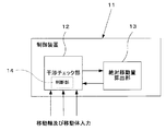
- the control device 11 includes a first main shaft 1 to a third main shaft 6 and a first tool post 2 to a fourth tool post 7 that constitute a moving body in the machine tool.
- An interference check unit 12 for checking interference is provided. By inputting the information of each moving body to the interference check unit 12, interference between the moving bodies when the moving bodies perform processing movement or the like, or the fixed structure of the moving body and the machine tool. It is possible to check for interference and detect the presence or absence of interference.
- the interference check by the interference check unit 12 can use known means, but the interference check unit 12 includes a mobile object to be subjected to interference check and at least the X direction, Y direction, and Z direction of the mobile body. It is necessary to input and set the movement axis corresponding to the movement.
- the first tool post 2 and the fourth tool post 9 are input as a moving object to be subjected to the interference check, and the first tool post 2 is input to the first tool post 2.
- the X1 axis is input as the X direction movement axis
- the Y1 axis is input as the Y direction movement axis
- the Y4 axis is the Y direction movement axis with respect to the fourth tool post
- the Z4 axis is the Z direction movement axis.
- the interference check unit 12 of the present invention includes a plurality of (two or more) moving means for one moving direction of one moving body like the second tool post 4,
- An absolute movement amount calculation unit 13 that combines the movement amounts of the plurality of movement axes input in one movement direction and calculates the absolute movement amount of the moving body in the movement direction is provided in cooperation. ing. As shown in FIG. 2, when a determination unit 14 is provided in the interference check unit 12 and the determination unit 14 determines that a plurality of movement axes exist for one moving body from among the plurality of input movement axes.
- the absolute movement amount calculation unit 13 may be configured to synthesize the movement amounts of the movement axes.
- the determination unit 14 may be provided in the absolute movement amount calculation unit 13 or may be provided separately from the interference check unit 12 and the absolute movement amount calculation unit 13.
- the interference check unit 12 and the absolute movement amount calculation unit 13 or these and the determination unit 14 constitute an interference check device.
- the absolute movement amount calculation unit 13 determines the movement amount on the Y2 axis of the second tool rest 4 with respect to the moving stand 8 by the moving means in the Y2 axis direction of the second tool rest 4 and the A2 of the moving stand 8.
- a virtual movement axis (Y-direction virtual axis) of the second tool post 4 with respect to the bed is formed, and the first movement in the Y-direction virtual axis is formed.
- the absolute movement amount (that is, the position on the coordinates) of the two tool rests 4 is obtained.
- the absolute movement amount can be determined in advance with reference to a predetermined reference position of the machine tool, for example, the end reference surface of the machine tool or the center of the first main shaft 1.
- the movement amount of the second tool post 4 on the Y-direction virtual axis obtained by the absolute movement amount calculation unit 13 is input to the interference check unit 12, so that the second tool post 4 and another moving body or fixed body are fixed. Interference with structures etc. can be checked.
- step S ⁇ b> 1 the moving object to be subjected to interference check and the movement axis are input to the interference check unit 12.
- the second tool post 4 and the fourth tool post 9 may interfere with each other, each movement of the second main spindle 3, the second tool post 4 and the fourth tool post 9 is performed.
- the axis is input to the interference check unit 12.
- the A2 axis is input as the Y-direction movement axis of the second main spindle 3
- the Y2 axis and the A2 axis are input as the Y-direction movement axes of the second tool post 4.
- the movement axes of the first main spindle 1, the first tool post 2 and the fourth tool post 9 interfere with each other. Input to the check unit 12.
- the third main spindle 6, the third tool post 7 and the fourth tool post 9 may interfere with each other, the movement axes of the third main spindle 6, the third tool post 7 and the fourth tool post 9 are set. Input to the interference check unit 12.
- step S2 it is determined whether there are a plurality of movement axes for moving the same moving body in the same axial direction.
- the determination unit 14 can be configured to automatically perform the determination based on the input result. Further, without providing the determination unit 14, the operator may determine and input the plurality of movement axes to the interference check unit 12 so that the plurality of movement axes are input to the absolute movement amount calculation unit 13.
- the Y2 axis and the A2 axis input as the movement axis of the second tool post 4 are in the same axial direction, the Y2 axis as a plurality of movement axes for moving the second tool post 4 in the same axial direction, It is determined that the A2 axis exists. If it is determined in step S2 that there are a plurality of movement axes for moving the same moving body in the same axial direction, as shown in step S3, the absolute movement amount calculation unit 13 uses one virtual axis from the plurality of movement axes. A shaft is provided.
- a virtual Y-direction movement axis (Y-direction virtual axis) Y2 ′ axis obtained by synthesizing the Y2 axis and the A2 axis from the Y2 axis and the A2 axis that are the movement axes of the second tool post 4 is provided.
- the two A2 axes and the Y2 axis in the Y direction of the second tool post 4 are replaced with the Y2 ′ axis which is one Y direction virtual axis, and the process proceeds to step S4.
- step S2 If it is determined in step S2 that there are not a plurality of moving axes for moving the same moving body in the same axial direction, the process proceeds to the next step S4 without providing a virtual axis.
- step S4 the interference check unit 12 performs an interference check based on the movement amount of each movement axis and the absolute movement amount on the virtual axis.
- FIG. 4 shows an example of an interference check between the second tool post 4 and the fourth tool post 9 in which the Y2 ′ axis that is the Y-direction virtual axis is set.
- An interference check region region 4a surrounded by a dotted line
- an interference check region (dotted line including the fourth tool post 9 and the tool T attached thereto).
- the enclosed area 9a) is set in advance. Then, from the current position of the second tool post 4 and the fourth tool post 9, the second tool post 4 moves on the Y2 'axis and X2 based on movement commands in the X2, Y2, and A2 directions with respect to the second tool post 4. Find the position on the axis to move to.
- the interference check unit 12 is provided with the second tool rest. 4 and the fourth turret 9 are judged to cause interference, the movement of the second turret 4 and the fourth turret 9 is restricted, and an alarm or the like is notified.
- a plurality of moving means are provided for one moving direction of one moving body by linking the interference checking unit 12 and the absolute movement amount calculating unit 13. In addition, it is possible to easily check the interference of the moving body.
- the interference check unit 12 and the absolute movement amount calculation unit 13 may be provided in the same control device 11 or may be provided separately from the control device 11. Further, the interference check unit 12 and the absolute movement amount calculation unit 13 may be separate or integrated. Further, the absolute movement amount calculation unit 13 may be activated when a plurality of movement axes in the same direction are input to the interference check unit 12 with respect to one moving body.
- the input unit of the movement axis can be configured to arbitrarily set the movement direction corresponding to the input movement axis
- the structure can input a plurality of movement axes in advance for one movement direction, or each movement Input multiple movement axes in one movement direction by inputting a single movement axis for each direction and using a separate movement axis so that the movement direction can be set arbitrarily. can do.
- the Y direction moving axis of the second tool post 4 is taken as an example, and the Y2 axis and the A2 axis are combined to form the Y2 ′ axis that is the Y direction virtual axis.
- the moving body is not limited to the tool post and may be a main spindle or other moving bodies.
- the present invention is applicable not only to the Y direction but also to a case where there are a plurality of movement axes in the X direction and the Z direction.
- the number of moving axes to be combined is not limited to two, and the present invention can be applied to three or more moving axes.
- the absolute movement amount calculation unit 13 may be provided for each of the movement axes in the X, Y, and Z directions, or a common absolute movement amount calculation unit 13 may be provided for each of the movement axes in the X, Y, and Z directions. Good.
- the present invention is not limited to the case where there are a plurality of moving bodies and the mutual interference check of each moving body and the interference check between each moving body and the fixed portion are performed.
- the present invention can also be applied when checking for interference.
- the interference check device and method of the present invention are not limited to machine tools, and can be applied to any device that needs to perform an interference check.
Abstract
Description
一方、複数の刃物台を備えた工作機械において、刃物台同士又は刃物台と固定的な構造物等との干渉をチェックする干渉チェック装置が公知となっている(例えば特許文献2参照)。 Conventionally, as shown in FIG. 4 of
On the other hand, in a machine tool including a plurality of tool rests, an interference check device for checking interference between tool rests or between a tool rest and a fixed structure is known (for example, see Patent Document 2).
さらに、入力された移動軸の中に、同一の移動体について同じ軸線方向に移動させるための移動軸が複数存在するか否かを判断する判断部を設けてもよい。 Further, the absolute movement amount calculation unit combines a plurality of movement axes in the same axial direction by the plurality of moving means, and provides a virtual axis in the same axial direction as the movement axis, and based on the virtual axis, the absolute movement amount is calculated. You may comprise so that a movement amount may be calculated | required.
Furthermore, a determination unit may be provided that determines whether there are a plurality of movement axes for moving the same moving body in the same axial direction among the input movement axes.
第1刃物台2は、Z1軸と直交し、且つ互いに直交するX1軸及びY1軸方向に移動可能なXYテーブルに設けられている。第1刃物台2は、このXYテーブルとともにX1軸方向及びY1軸方向に移動可能である。前記XYテーブルは、第1刃物台2のX1軸方向の移動手段を構成するX1軸用モータと送りネジ機構等によってX1軸方向に移動し、第1刃物台のY1軸方向の移動手段を構成するY1軸用モータと送りネジ機構等によってY1軸方向に移動する。 The first
The
また、前述のようにX1軸方向,X2軸方向,X3軸方向が同じ軸線方向であり、Y1軸方向,Y2軸方向,A2軸方向,Y3軸方向,Y4軸方向が同じ軸線方向であり、Z1軸方向,Z2軸方向,Z3軸方向,Z4軸方向が同じ軸線方向であるため、以下では、X1軸,X2軸,X3軸上の移動方向をX方向、Y1軸,Y2軸,A2軸,Y3軸,Y4軸上の移動方向をY方向、Z1軸,Z2軸,Z3軸,Z4軸上の移動方向をZ方向と称することがある。 In FIG. 1, “+” indicates the direction of movement of each moving body. For example, in the
Further, as described above, the X1 axis direction, the X2 axis direction, and the X3 axis direction are the same axis direction, and the Y1 axis direction, the Y2 axis direction, the A2 axis direction, the Y3 axis direction, and the Y4 axis direction are the same axis direction, Since the Z1 axis direction, the Z2 axis direction, the Z3 axis direction, and the Z4 axis direction are the same axial direction, the movement directions on the X1 axis, the X2 axis, and the X3 axis will be referred to as the X direction, the Y1, A2, Y2, and A2 axes. , The movement direction on the Y3 axis and the Y4 axis may be referred to as the Y direction, and the movement direction on the Z1 axis, the Z2 axis, the Z3 axis, and the Z4 axis may be referred to as the Z direction.
図2に示すように、干渉チェック部12に判断部14を設け、この判断部14が、入力された複数の移動軸の中から、一つの移動体について複数の移動軸が存在すると判断したときに、絶対移動量算出部13が当該移動軸の各々の移動量を合成するように構成してもよい。もちろん、判断部14は絶対移動量算出部13に設けてもよいし、干渉チェック部12及び絶対移動量算出部13と別体に設けてもよい。
この実施形態では、干渉チェック部12と絶対移動量算出部13又はこれらと判断部14とで干渉チェック装置が構成される。 When the
As shown in FIG. 2, when a
In this embodiment, the
ステップS1において、干渉チェックの対象となる移動体と、その移動軸を干渉チェック部12に入力する。この実施形態では、第2主軸3,第2刃物台4及び第4刃物台9は互いに干渉する可能性があるため、第2主軸3,第2刃物台4及び第4刃物台9の各移動軸を干渉チェック部12に入力する。このとき、第2主軸3のY方向移動軸としてA2軸を入力し、第2刃物台4のY方向の移動軸としてY2軸とA2軸とを入力する。また、第1主軸1,第1刃物台2及び第4刃物台9は互いに干渉する可能性があるため、第1主軸1,第1刃物台2及び第4刃物台9の各移動軸を干渉チェック部12に入力する。同様に、第3主軸6,第3刃物台7及び第4刃物台9は互いに干渉する可能性があるため、第3主軸6,第3刃物台7及び第4刃物台9の各移動軸を干渉チェック部12に入力する。 An example of the operation of the absolute movement
In step S <b> 1, the moving object to be subjected to interference check and the movement axis are input to the
ステップS2で同一の移動体について同じ軸線方向に移動させるための移動軸が複数あると判断した場合は、ステップS3に示すように、絶対移動量算出部13が当該複数の移動軸から一つの仮想軸を設ける。この実施形態では、第2刃物台4の移動軸であるY2軸とA2軸とから、Y2軸とA2軸を合成した仮想のY方向移動軸(Y方向仮想軸)Y2′軸を設ける。これにより第2刃物台4のY方向の二つのA2軸,Y2軸が、一つのY方向仮想軸であるY2′軸に置き換えられ、ステップS4に進む。
なお、ステップS2で同一の移動体について同じ軸線方向に移動させるための移動軸が複数存在しないと判断した場合は、仮想軸を設けることなく、次のステップS4に進む。そして、ステップS4で、干渉チェック部12が各移動軸の移動量及び仮想軸における前記絶対移動量から、干渉チェックを行う。 Next, as shown in step S2, it is determined whether there are a plurality of movement axes for moving the same moving body in the same axial direction. When the
If it is determined in step S2 that there are a plurality of movement axes for moving the same moving body in the same axial direction, as shown in step S3, the absolute movement
If it is determined in step S2 that there are not a plurality of moving axes for moving the same moving body in the same axial direction, the process proceeds to the next step S4 without providing a virtual axis. In step S4, the
このようにして、本発明では、干渉チェック部12と絶対移動量算出部13との連係により、一つの移動体の一つの移動方向に対して複数の移動手段が設けられている場合であっても、当該移動体の干渉チェックを容易に行うことができる。 Further, based on the movement command in the Z4 direction and the Y4 direction with respect to the
In this way, in the present invention, a plurality of moving means are provided for one moving direction of one moving body by linking the
例えば、干渉チェック部12と絶対移動量算出部13とは同一の制御装置11に設けてもよいし、制御装置11とは別に設けてもよい。また、干渉チェック部12と絶対移動量算出部13とは別体であってもよいし一体であってもよい。さらに、干渉チェック部12に、一つの移動体に対して同方向の複数の移動軸が入力されたときに、絶対移動量算出部13が起動されるように構成してもよい。 Although preferred embodiments of the present invention have been described, the present invention is not limited to the above-described embodiments.
For example, the
2 第1刃物台(移動体)
3 第2主軸(移動体)
4 第2刃物台(移動体)
6 第3主軸(移動体)
7 第3刃物台(移動体)
8 移動台
9 第4刃物台(移動体)
11 制御装置
12 干渉チェック部
13 絶対移動量算出部
14 判断部 1 First spindle (moving body)
2 First tool post (moving body)
3 Second spindle (moving body)
4 Second tool post (moving body)
6 Third spindle (moving body)
7 Third tool post (moving body)
8 Moving table 9 4th tool post (moving body)
DESCRIPTION OF
Claims (6)
- 所定方向に移動可能な移動体と、この移動体を移動させる移動手段とを備えるとともに、一つの前記移動体を同じ軸線方向に移動させる移動手段を複数有する装置に設けられ、前記移動体が移動する際の干渉チェックを行う干渉チェック装置において、
前記複数の移動手段による前記移動体の同方向の移動量を合成して、当該方向の絶対移動量を求める絶対移動量算出部と、
この絶対移動量算出部と連係して設けられ、前記絶対移動量により前記干渉チェックを行う干渉チェック部と、
を有することを特徴とする干渉チェック装置。 A moving body that is movable in a predetermined direction and a moving means that moves the moving body are provided in an apparatus that includes a plurality of moving means that move one moving body in the same axial direction, and the moving body moves. In the interference check device that performs the interference check when
An absolute movement amount calculation unit that combines the movement amounts of the moving body in the same direction by the plurality of moving units to obtain an absolute movement amount in the direction;
An interference check unit that is provided in conjunction with the absolute movement amount calculation unit and performs the interference check based on the absolute movement amount;
An interference check device comprising: - 前記絶対移動量算出部は、前記複数の移動手段による同じ軸線方向の複数の移動軸を合成して、前記移動軸と同じ軸線方向に仮想軸を設け、この仮想軸に基づいて前記絶対移動量を求めることを特徴とする請求項1に記載の干渉チェック装置。 The absolute movement amount calculation unit synthesizes a plurality of movement axes in the same axial direction by the plurality of moving means, provides a virtual axis in the same axial direction as the movement axis, and based on the virtual axis, the absolute movement amount 2. The interference check device according to claim 1, wherein:
- 入力された移動軸の中に、同一の移動体について同じ軸線方向に移動させるための移動軸が複数存在するか否かを判断する判断部を有することを特徴とする請求項1又は2に記載の干渉チェック装置。 3. The determination unit according to claim 1, further comprising: a determination unit configured to determine whether or not there are a plurality of movement axes for moving the same moving body in the same axis direction among the input movement axes. Interference check device.
- 所定方向に移動可能な移動体と、この移動体を移動させる移動手段とを備えるとともに、一つの前記移動体を同じ軸線方向に移動させる移動手段を複数有する装置における前記移動体が移動する際の干渉チェックを行う干渉チェック方法において、
干渉する可能性のある移動体を指定し、この移動体の移動軸を入力するステップと、
入力された移動軸の中に、同一の移動体について同じ軸線方向に移動させる移動軸が複数存在するか否かを判断し、存在すると判断した場合に前記複数の移動軸と同じ軸線方向の移動量を合成して当該移動方向の絶対移動量を求めるステップと、
前記絶対移動量により前記干渉チェックを行うステップと、
を有することを特徴とする干渉チェック方法。 A moving body that is movable in a predetermined direction; and a moving means that moves the moving body, and the moving body in an apparatus that has a plurality of moving means that moves one moving body in the same axial direction. In the interference check method for performing interference check,
Designating a moving object that may interfere, and inputting the moving axis of the moving object;
It is determined whether or not there are a plurality of moving axes that are moved in the same axial direction for the same moving body among the input moving axes. Combining the amount to obtain the absolute movement amount in the movement direction;
Performing the interference check according to the absolute movement amount;
An interference check method comprising: - 同一の移動体について同じ軸線方向に移動させるための移動軸が複数存在すると判断した場合に、複数の前記移動軸と同じ軸線方向に一つの仮想軸を設け、この仮想軸に基づいて前記絶対移動量を求めることを特徴とする請求項4に記載の干渉チェック方法。 When it is determined that there are a plurality of moving axes for moving the same moving body in the same axial direction, one virtual axis is provided in the same axial direction as the plurality of moving axes, and the absolute movement is performed based on the virtual axis. The interference check method according to claim 4, wherein an amount is obtained.
- 請求項1~3のいずれかに記載の干渉チェック装置を備えたことを特徴とする工作機械。 A machine tool comprising the interference check device according to any one of claims 1 to 3.
Priority Applications (5)
| Application Number | Priority Date | Filing Date | Title |
|---|---|---|---|
| ES09794404.5T ES2579434T3 (en) | 2008-07-10 | 2009-07-06 | Interference checking device, interference checking procedure, and machine tool that has the interference checking device |
| CN200980126679.6A CN102089722B (en) | 2008-07-10 | 2009-07-06 | Interference check device, interference check method, and machine tool having the interference check device |
| US12/737,358 US9110459B2 (en) | 2008-07-10 | 2009-07-06 | Interference check device, interference check method, and machine tool having the interference check device |
| EP09794404.5A EP2306253B1 (en) | 2008-07-10 | 2009-07-06 | Interference check device, interference check method, and machine tool having the interference check device |
| JP2010519769A JP5554235B2 (en) | 2008-07-10 | 2009-07-06 | Interference check device, interference check method, and machine tool provided with interference check device |
Applications Claiming Priority (2)
| Application Number | Priority Date | Filing Date | Title |
|---|---|---|---|
| JP2008179912 | 2008-07-10 | ||
| JP2008-179912 | 2008-07-10 |
Publications (1)
| Publication Number | Publication Date |
|---|---|
| WO2010004960A1 true WO2010004960A1 (en) | 2010-01-14 |
Family
ID=41507073
Family Applications (1)
| Application Number | Title | Priority Date | Filing Date |
|---|---|---|---|
| PCT/JP2009/062302 WO2010004960A1 (en) | 2008-07-10 | 2009-07-06 | Interference check device, interference check method, and machine tool having the interference check device |
Country Status (8)
| Country | Link |
|---|---|
| US (1) | US9110459B2 (en) |
| EP (1) | EP2306253B1 (en) |
| JP (1) | JP5554235B2 (en) |
| KR (1) | KR101575780B1 (en) |
| CN (1) | CN102089722B (en) |
| ES (1) | ES2579434T3 (en) |
| TW (1) | TWI477933B (en) |
| WO (1) | WO2010004960A1 (en) |
Cited By (2)
| Publication number | Priority date | Publication date | Assignee | Title |
|---|---|---|---|---|
| JP2020044646A (en) * | 2018-09-19 | 2020-03-26 | ウーテーアー・エス・アー・マニファクチュール・オロロジェール・スイス | Machining center for timepiece components |
| WO2022264338A1 (en) * | 2021-06-16 | 2022-12-22 | ファナック株式会社 | Control device, interference checking device, and control system |
Families Citing this family (10)
| Publication number | Priority date | Publication date | Assignee | Title |
|---|---|---|---|---|
| US5300034A (en) * | 1992-07-29 | 1994-04-05 | Minnesota Mining And Manufacturing Company | Iv injection site for the reception of a blunt cannula |
| CN103707109B (en) * | 2013-12-26 | 2016-07-06 | 北京航空航天大学 | A kind of circumference array curved-surface structure five axle synchronous processing device |
| EP2998066B1 (en) * | 2014-09-19 | 2017-06-14 | Mikron Agie Charmilles AG | High voltage crash prevention device for machine tools |
| JP6411964B2 (en) * | 2015-07-27 | 2018-10-24 | ファナック株式会社 | Real-time interference confirmation system for machine tools and robots |
| TWI697379B (en) * | 2015-09-24 | 2020-07-01 | 日商西鐵城時計股份有限公司 | Control device of machine tool and machine tool provided with the control device |
| JP6687582B2 (en) * | 2017-11-30 | 2020-04-22 | ファナック株式会社 | Information processing equipment |
| DE102018123363B4 (en) * | 2018-09-24 | 2021-01-07 | Bystronic Laser Ag | Procedure for collision avoidance and laser processing machine |
| DE102018125620A1 (en) * | 2018-10-16 | 2020-04-16 | Schuler Pressen Gmbh | Method and device for cutting a sheet metal blank from a continuously conveyed sheet metal strip |
| DE102020206223A1 (en) | 2020-05-18 | 2021-11-18 | Sms Group Gmbh | Crosshead for use as an upper and / or lower beam in a press |
| CH718535B1 (en) * | 2022-03-23 | 2023-03-15 | Reishauer Ag | Method and machine tool system for collision checking of a machining process, with a replacement workpiece. |
Citations (2)
| Publication number | Priority date | Publication date | Assignee | Title |
|---|---|---|---|---|
| JP3464307B2 (en) | 1995-03-24 | 2003-11-10 | シチズン時計株式会社 | Interference check method in NC lathe |
| JP2006255794A (en) | 2005-03-15 | 2006-09-28 | Tsugami Corp | Automatic lathe |
Family Cites Families (11)
| Publication number | Priority date | Publication date | Assignee | Title |
|---|---|---|---|---|
| JPS58155150A (en) * | 1982-03-11 | 1983-09-14 | Yamazaki Mazak Corp | Decision control of simultaneous machining for four-axis numerical controlled lathe |
| JPS63156601A (en) * | 1986-12-22 | 1988-06-29 | Matsuo Sangyo Kk | Automatic machine tool |
| US5127140A (en) * | 1989-12-18 | 1992-07-07 | Hitachi Seiki Co., Ltd. | Numerically-controlled lathe, numerically-controlled device therefor and processing procedure thereby |
| JPH04291605A (en) * | 1991-03-20 | 1992-10-15 | Matsushita Electric Ind Co Ltd | Working device having interference preventing function |
| JPH0852638A (en) * | 1994-08-15 | 1996-02-27 | Toshiba Mach Co Ltd | Interference check method, machining program check method and machining suitability check method |
| JP3563191B2 (en) * | 1996-02-26 | 2004-09-08 | 三菱電機株式会社 | Numerical control unit |
| JPH11170117A (en) * | 1997-12-11 | 1999-06-29 | Sodick Co Ltd | Controlling method and device for moving spindle of machine tool |
| US6651279B1 (en) * | 2002-11-26 | 2003-11-25 | Ge Medical Systems Global Technology Company, Llc | Method and apparatus for collision avoidance in a patient positioning platform |
| JP4666675B2 (en) * | 2004-04-19 | 2011-04-06 | シチズンホールディングス株式会社 | Machining method of workpiece on numerically controlled lathe |
| JP2008027045A (en) * | 2006-07-19 | 2008-02-07 | Fanuc Ltd | Numerical control apparatus provided with interference checking function |
| JP2009142915A (en) * | 2007-12-12 | 2009-07-02 | Murata Mach Ltd | Machine tool and machining method using the same |
-
2009
- 2009-07-06 KR KR1020117000284A patent/KR101575780B1/en not_active IP Right Cessation
- 2009-07-06 ES ES09794404.5T patent/ES2579434T3/en active Active
- 2009-07-06 WO PCT/JP2009/062302 patent/WO2010004960A1/en active Application Filing
- 2009-07-06 JP JP2010519769A patent/JP5554235B2/en not_active Expired - Fee Related
- 2009-07-06 US US12/737,358 patent/US9110459B2/en not_active Expired - Fee Related
- 2009-07-06 EP EP09794404.5A patent/EP2306253B1/en not_active Not-in-force
- 2009-07-06 CN CN200980126679.6A patent/CN102089722B/en not_active Expired - Fee Related
- 2009-07-10 TW TW098123506A patent/TWI477933B/en not_active IP Right Cessation
Patent Citations (2)
| Publication number | Priority date | Publication date | Assignee | Title |
|---|---|---|---|---|
| JP3464307B2 (en) | 1995-03-24 | 2003-11-10 | シチズン時計株式会社 | Interference check method in NC lathe |
| JP2006255794A (en) | 2005-03-15 | 2006-09-28 | Tsugami Corp | Automatic lathe |
Non-Patent Citations (1)
| Title |
|---|
| See also references of EP2306253A4 * |
Cited By (3)
| Publication number | Priority date | Publication date | Assignee | Title |
|---|---|---|---|---|
| JP2020044646A (en) * | 2018-09-19 | 2020-03-26 | ウーテーアー・エス・アー・マニファクチュール・オロロジェール・スイス | Machining center for timepiece components |
| US11524381B2 (en) | 2018-09-19 | 2022-12-13 | Eta Sa Manufacture Horlogere Suisse | Machining centre for timepiece components |
| WO2022264338A1 (en) * | 2021-06-16 | 2022-12-22 | ファナック株式会社 | Control device, interference checking device, and control system |
Also Published As
| Publication number | Publication date |
|---|---|
| US9110459B2 (en) | 2015-08-18 |
| CN102089722A (en) | 2011-06-08 |
| EP2306253B1 (en) | 2016-05-04 |
| US20110106291A1 (en) | 2011-05-05 |
| EP2306253A4 (en) | 2013-06-26 |
| CN102089722B (en) | 2014-07-23 |
| JPWO2010004960A1 (en) | 2012-01-05 |
| KR101575780B1 (en) | 2015-12-08 |
| JP5554235B2 (en) | 2014-07-23 |
| EP2306253A1 (en) | 2011-04-06 |
| KR20110026468A (en) | 2011-03-15 |
| TWI477933B (en) | 2015-03-21 |
| ES2579434T3 (en) | 2016-08-11 |
| TW201015256A (en) | 2010-04-16 |
Similar Documents
| Publication | Publication Date | Title |
|---|---|---|
| WO2010004960A1 (en) | Interference check device, interference check method, and machine tool having the interference check device | |
| US10088824B2 (en) | Toolpath evaluation method, toolpath generation method, and toolpath generation device | |
| US20090164038A1 (en) | Method for optimizing the machining process in a machine | |
| WO2014132846A1 (en) | Collision avoidance system for machine tool | |
| JP2010105072A (en) | Compound lathe | |
| JP2015225617A (en) | Numerical value control device and control method | |
| JP2006155530A (en) | Numerical controller and numerical control machine tool | |
| JP2008090463A (en) | Working control method and working information preparation method in machine tool | |
| TW201234149A (en) | Numerical control device | |
| US10133253B2 (en) | Operation limiting device for machine tool | |
| JP7154218B2 (en) | Machine Tools | |
| JP2007094458A (en) | Numerical control device | |
| US8352066B2 (en) | Machine tool, operating method for a machine tool and objects associated therewith | |
| JP2017091429A (en) | NC program creation device | |
| JP2007249671A (en) | Method for preventing collision in machine tool | |
| JP2008126371A (en) | Machine tool | |
| JP6935606B1 (en) | Information processing equipment and information processing programs | |
| JP5636841B2 (en) | Machining method and NC program creation device | |
| WO2022215476A1 (en) | Information processing device and information processing program | |
| JP4504286B2 (en) | How to change the stroke range of the tool post on a two-spindle facing lathe | |
| Bates | Move over machine tools here come robots | |
| JP4066178B2 (en) | Machine tool and its abnormality inspection method | |
| JP6604058B2 (en) | Program conversion device, plate material processing system, and plate material processing method | |
| JP5173936B2 (en) | Numerical controller | |
| JP2015047683A (en) | Processing method using cylindrical tool |
Legal Events
| Date | Code | Title | Description |
|---|---|---|---|
| WWE | Wipo information: entry into national phase |
Ref document number: 200980126679.6 Country of ref document: CN |
|
| 121 | Ep: the epo has been informed by wipo that ep was designated in this application |
Ref document number: 09794404 Country of ref document: EP Kind code of ref document: A1 |
|
| WWE | Wipo information: entry into national phase |
Ref document number: 2010519769 Country of ref document: JP |
|
| WWE | Wipo information: entry into national phase |
Ref document number: 12737358 Country of ref document: US |
|
| ENP | Entry into the national phase |
Ref document number: 20117000284 Country of ref document: KR Kind code of ref document: A |
|
| WWE | Wipo information: entry into national phase |
Ref document number: 2009794404 Country of ref document: EP |
|
| NENP | Non-entry into the national phase |
Ref country code: DE |