WO2010004876A1 - Image forming apparatus - Google Patents
Image forming apparatus Download PDFInfo
- Publication number
- WO2010004876A1 WO2010004876A1 PCT/JP2009/061589 JP2009061589W WO2010004876A1 WO 2010004876 A1 WO2010004876 A1 WO 2010004876A1 JP 2009061589 W JP2009061589 W JP 2009061589W WO 2010004876 A1 WO2010004876 A1 WO 2010004876A1
- Authority
- WO
- WIPO (PCT)
- Prior art keywords
- side plate
- image
- transfer belt
- forming apparatus
- image forming
- Prior art date
Links
Images


Classifications
-
- G—PHYSICS
- G03—PHOTOGRAPHY; CINEMATOGRAPHY; ANALOGOUS TECHNIQUES USING WAVES OTHER THAN OPTICAL WAVES; ELECTROGRAPHY; HOLOGRAPHY
- G03G—ELECTROGRAPHY; ELECTROPHOTOGRAPHY; MAGNETOGRAPHY
- G03G15/00—Apparatus for electrographic processes using a charge pattern
- G03G15/14—Apparatus for electrographic processes using a charge pattern for transferring a pattern to a second base
- G03G15/16—Apparatus for electrographic processes using a charge pattern for transferring a pattern to a second base of a toner pattern, e.g. a powder pattern, e.g. magnetic transfer
- G03G15/1605—Apparatus for electrographic processes using a charge pattern for transferring a pattern to a second base of a toner pattern, e.g. a powder pattern, e.g. magnetic transfer using at least one intermediate support
- G03G15/161—Apparatus for electrographic processes using a charge pattern for transferring a pattern to a second base of a toner pattern, e.g. a powder pattern, e.g. magnetic transfer using at least one intermediate support with means for handling the intermediate support, e.g. heating, cleaning, coating with a transfer agent
-
- G—PHYSICS
- G03—PHOTOGRAPHY; CINEMATOGRAPHY; ANALOGOUS TECHNIQUES USING WAVES OTHER THAN OPTICAL WAVES; ELECTROGRAPHY; HOLOGRAPHY
- G03G—ELECTROGRAPHY; ELECTROPHOTOGRAPHY; MAGNETOGRAPHY
- G03G15/00—Apparatus for electrographic processes using a charge pattern
- G03G15/01—Apparatus for electrographic processes using a charge pattern for producing multicoloured copies
- G03G15/0105—Details of unit
- G03G15/0131—Details of unit for transferring a pattern to a second base
-
- G—PHYSICS
- G03—PHOTOGRAPHY; CINEMATOGRAPHY; ANALOGOUS TECHNIQUES USING WAVES OTHER THAN OPTICAL WAVES; ELECTROGRAPHY; HOLOGRAPHY
- G03G—ELECTROGRAPHY; ELECTROPHOTOGRAPHY; MAGNETOGRAPHY
- G03G15/00—Apparatus for electrographic processes using a charge pattern
- G03G15/14—Apparatus for electrographic processes using a charge pattern for transferring a pattern to a second base
- G03G15/16—Apparatus for electrographic processes using a charge pattern for transferring a pattern to a second base of a toner pattern, e.g. a powder pattern, e.g. magnetic transfer
- G03G15/1605—Apparatus for electrographic processes using a charge pattern for transferring a pattern to a second base of a toner pattern, e.g. a powder pattern, e.g. magnetic transfer using at least one intermediate support
- G03G15/1615—Apparatus for electrographic processes using a charge pattern for transferring a pattern to a second base of a toner pattern, e.g. a powder pattern, e.g. magnetic transfer using at least one intermediate support relating to the driving mechanism for the intermediate support, e.g. gears, couplings, belt tensioning
-
- G—PHYSICS
- G03—PHOTOGRAPHY; CINEMATOGRAPHY; ANALOGOUS TECHNIQUES USING WAVES OTHER THAN OPTICAL WAVES; ELECTROGRAPHY; HOLOGRAPHY
- G03G—ELECTROGRAPHY; ELECTROPHOTOGRAPHY; MAGNETOGRAPHY
- G03G2215/00—Apparatus for electrophotographic processes
- G03G2215/01—Apparatus for electrophotographic processes for producing multicoloured copies
- G03G2215/0103—Plural electrographic recording members
- G03G2215/0119—Linear arrangement adjacent plural transfer points
- G03G2215/0138—Linear arrangement adjacent plural transfer points primary transfer to a recording medium carried by a transport belt
- G03G2215/0148—Linear arrangement adjacent plural transfer points primary transfer to a recording medium carried by a transport belt the linear arrangement being slanted
-
- G—PHYSICS
- G03—PHOTOGRAPHY; CINEMATOGRAPHY; ANALOGOUS TECHNIQUES USING WAVES OTHER THAN OPTICAL WAVES; ELECTROGRAPHY; HOLOGRAPHY
- G03G—ELECTROGRAPHY; ELECTROPHOTOGRAPHY; MAGNETOGRAPHY
- G03G2215/00—Apparatus for electrophotographic processes
- G03G2215/01—Apparatus for electrophotographic processes for producing multicoloured copies
- G03G2215/019—Structural features of the multicolour image forming apparatus
- G03G2215/0193—Structural features of the multicolour image forming apparatus transfer member separable from recording member
Definitions
- the present invention relates to an image forming apparatus such as a printer, a copying machine, and a facsimile using an electrophotographic system, and a toner image formed on an image carrier is physically applied onto a recording sheet by a transfer device having a rotating transfer belt.
- the present invention relates to an image forming apparatus that transports a recording sheet to which a toner image is adhered to a fixing device after the transfer and performs fixing.
- an image forming apparatus using an electrophotographic system develops a latent image carried on a photosensitive member into a toner image by a developing device, then transfers the toner image onto a recording sheet, and transfers the transferred image to the recording sheet. And an image forming process for fixing to the image.
- a toner image is directly transferred from a photosensitive drum, which is an image carrier, onto a recording sheet, and a toner image formed on the photosensitive drum is primarily transferred onto the surface of an intermediate transfer member, which is an image carrier.
- an intermediate transfer member which is an image carrier.
- Many of the intermediate transfer members include an intermediate transfer belt wound around a plurality of rolls as an image carrier.
- the transfer device As a transfer device for transferring the toner image on the image carrier to a recording sheet, the transfer device is provided with a transfer belt facing the roller for stretching the photosensitive drum or the intermediate transfer belt, and a pressing roller for pressing the transfer belt. Things are known.
- the transfer device sandwiches a recording sheet between an image carrier and a transfer belt, presses the transfer belt against the image carrier by a pressing roller, and passes the transfer belt while applying a transfer bias. The image formed on the surface is transferred.
- the transfer belt is of a type in which the recording paper is pressed against the circumferential surface of the image carrier and the toner image is transferred while being conveyed at a constant speed. It needs to be said.
- the transfer belt is a wide belt as is well known, it is difficult to uniformly press the transfer belt against the image bearing member, and there is a possibility that unevenness in image density may occur due to the pressure difference.
- a transfer belt for transferring the toner image on the photosensitive drum (image carrier) to the recording paper and transporting the recording paper is provided, and the left and right sides of the driven shaft side are centered on the drive shaft on which the transfer belt is stretched.
- a transfer conveyance unit is disclosed in which both ends are lifted by two compression springs and at least one of the shaft support portions of the drive shaft can be swung around the other shaft support portion (see, for example, Patent Document 1). ).
- Patent Document 1 the left and right end portions on the driven shaft side are lifted by two compression springs around the drive shaft on which the transfer belt is stretched, and at least one of the shaft support portions of the drive shaft serving as a pressing fulcrum is the other It is made to be able to swing around the shaft support part so that it can follow the inclination of the image carrier.
- the vertical displacement (inclination) between the image carrier and the pressure roller it is difficult to absorb the lateral displacement (inclination).
- the present invention has been made in view of the above situation, and the parallelism between the pressing roller and the roller that stretches the photosensitive drum that is the image bearing member and the intermediate transfer belt that is also the image bearing member facing the pressing roller is up, down, left, and right. It is an object of the present invention to provide an image forming apparatus including a transfer device that can prevent transfer failure and obtain a high-quality image.
- An image forming apparatus comprising: an image carrier that carries a toner image; and a transfer device that transfers a toner image formed on the image carrier to a recording paper, the transfer device comprising: an endless transfer belt; A plurality of rollers that stretch the transfer belt, including a pressing roller that presses the transfer belt against the image carrier, and a pair of integrated support side plates that rotatably support the plurality of rollers A pair of pressing side plates supported by a support member provided on a frame body of the transfer device so as to be rotatable in a direction contacting and separating from the image carrier, and provided on the pressing side plate, When the image carrier is pressed, a swinging portion that supports the support side plate so as to be swingable with respect to the image carrier, and the pressing side plate is biased in a direction in which the transfer belt presses the image carrier. And an urging member That the image forming apparatus.
- the swinging portion biases the support side plate in a direction in which the transfer belt presses the image carrier, and a second support member that rotatably supports the support side plate provided on the pressure side plate.
- the swinging portion includes an elastic deformation member at a substantially intermediate portion between a connecting portion between the pressing side plate and the supporting member and a connecting portion between the pressing side plate and the supporting side plate.
- the oscillating portion includes an elastically deformable structural portion in a part of the pressing side plate between a connecting portion between the pressing side plate and the supporting member and a connecting portion between the pressing side plate and the supporting side plate.
- the transfer belt is moved to the photosensitive drum or the intermediate transfer belt. It can be pressed so as to follow, and the pressing force can be made uniform. As a result, transfer defects can be reduced, and high-quality images can be obtained. Further, since the transfer belt is not twisted, it is possible to prevent the shift, and to improve the running stability of the transfer belt.
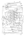
- FIG. 1 is a schematic diagram illustrating an example of an image forming apparatus according to the present invention.
- 2 is a partial view of a transfer device according to the present invention.
- FIG. It is a side view of the transfer device according to the present invention.
- 1 is a perspective view of a transfer device according to the present invention. It is a figure which shows the state which the back
- FIG. 1 is a schematic view showing an example of an image forming apparatus provided with a transfer device according to the present invention.
- the image forming apparatus includes an image forming apparatus main body GH and an image reading apparatus YS.
- the image forming apparatus main body GH is called a tandem type color image forming apparatus, and includes a plurality of image forming units 10Y, 10M, 10C, and 10K, and an intermediate transfer belt 6 that is an endless belt-like intermediate transfer body.
- the unit 60, the transfer device 70, a paper feed / conveying member, and a fixing device 9 are included.
- an image reading device YS comprising an automatic document feeder 201 and a document image scanning exposure device 202 is installed.
- the document d placed on the document table of the automatic document feeder 201 is transported by a transport member, and an image on one or both sides of the document is scanned and exposed by the optical system of the document image scanning exposure device 202, and is applied to the line image sensor CCD. Is read.
- a signal formed by photoelectric conversion by the line image sensor CCD is subjected to analog processing, A / D conversion, shading correction, image compression processing, and the like in an image processing unit, and then an exposure device 3Y, 3M, 3C, 3K. Sent to.
- the image forming unit 10Y that forms a yellow (Y) image has a charging device 2Y, an exposure device 3Y, a developing device 4Y, and a cleaning member 8Y arranged around the photosensitive drum 1Y.
- a charging device 2M, an exposure device 3M, a developing device 4M, and a cleaning member 8M are arranged around the photosensitive drum 1M.
- a charging device 2C, an exposure device 3C, a developing device 4C, and a cleaning member 8C are disposed around the photosensitive drum 1C.
- a charging device 2K, an exposure device 3K, a developing device 4K, and a cleaning member 8K are disposed around the photosensitive drum 1K.
- the charging device 2Y and the exposure device 3Y, the charging device 2M and the exposure device 3M, the charging device 2C and the exposure device 3C, and the charging device 2K and the exposure device 3K constitute a latent image forming unit.
- the intermediate transfer belt 6 is wound around a plurality of rollers and is rotatably supported.
- the fixing device 9 is stretched between a first pressure roller 93 having an elastic layer on a metal core, a heating roller 92 having a heating member therein, and between the first pressure roller 93 and the heating roller 92.
- An endless fixing belt 91 and a second pressure roller 94 which is disposed in a position facing the first pressure roller 93 so as to be in pressure contact with the fixing belt 91 and forms a fixing nip portion.
- the unfixed toner surface of the recording paper P carrying the toner passes through the fixing nip portion in a direction in contact with the fixing belt 91 so that the unfixed toner is fixed to the recording paper P by heating and pressing.
- each color image formed by the image forming units 10Y, 10M, 10C, and 10K is sequentially superimposed and transferred onto the rotating intermediate transfer belt 6 by the transfer members 7Y, 7M, 7C, and 7K (primary transfer). ), An image obtained by combining the color images is formed.
- the recording paper P stored in the paper feeding cassette 20 is fed by the paper feeding member 21 and is conveyed to the transfer device 70 through the paper feeding rollers 22A, 22B, 22C, 22D, the registration rollers 23, etc.
- a color image is transferred onto P (secondary transfer).
- the recording paper P onto which the color image has been transferred is heated and pressurized by the fixing device 9 so that the color image on the recording paper P is fixed. Thereafter, the sheet is sandwiched between the sheet discharge rollers 24 and placed on the sheet discharge tray 25 outside the apparatus.
- the residual toner is removed by the cleaning member 8A from the intermediate transfer belt 6 that has separated the curvature of the recording paper P.
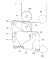
- FIG. 2 is a partial view of the transfer device 70.
- the intermediate transfer belt 6 is stretched around a plurality of rollers 61.
- the roller that sandwiches the intermediate transfer belt 6 and faces the pressing roller 702 is referred to as a backup roller 61A.
- the transfer device 70 has an endless transfer belt 701 stretched around a plurality of rollers.
- a pressure roller 702 and a tension roller 703 are used as a plurality of rollers.
- the pressure roller 702 and the tension roller 703 are rotatably supported by a pair of support side plates 710 disposed on the front side and the back side of the drawing.
- the pair of support side plates 710 are connected and integrated by a connecting member 711.
- a pair of pressing side plates 731 disposed on the front side and the rear side of the drawing are rotatable by a support member 741 provided on a frame (not shown) of the transfer device 70 in a direction in which the intermediate transfer belt 6 is contacted and separated. Supported.
- the support side plate 710 is supported by a swinging portion provided on the pressing side plate 731 so that the support side plate 710 can swing with respect to the intermediate transfer belt 6 when the transfer belt 701 is pressed against the intermediate transfer belt 6.
- the swinging portion is provided on the pressing side plate 731 and is a supporting member 721 that is a second supporting member that supports the supporting side plate 710, and a second member that biases the supporting side plate 710 in a direction in which the pressing roller 702 presses the backup roller 61A.
- a tension spring 723 which is an urging member.
- the tension spring 723 is disposed so as to act between the support side plate 710 and the pressing side plate 731.
- a receiving member of the support side plate 710 that engages with the support member 721 it is preferable to use, for example, a self-aligning bearing (not shown) that can swing with respect to the support member 721.
- the pressing side plate 731 is provided with a regulating member 722 that engages with the long hole of the supporting side plate 710 and regulates the swing range of the supporting side plate.
- the pair of pressing side plates 731 is urged in a direction in which the pressing roller 702 presses the backup roller 61A by a compression spring 743 which is an urging member provided between the pair of urging arms 742.
- the urging arm 742 is rotatably supported by the support member 741 and is swung by the cam 744. Thereby, energization and cancellation of energization are performed.
- the pressing roller 702 is pressed against the backup roller 61 by the compression spring 743 and the tension spring 723 by swinging the urging arm leftward in FIG. 2 (position shown in FIG. 2) by the cam 744.
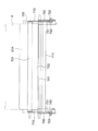
- FIG. 3 is a side view of the transfer device 70 as viewed from the direction of arrow A in FIG. 2, and FIG. 4 is a perspective view.
- FIG. 2 shows a case where the axis of the backup roller 61A and the axis of the pressing roller 702 are parallel.
- the pressing roller 702 is pressed uniformly against the backup roller 61A, the pressing force between the transfer belt 701 and the intermediate transfer belt 6 becomes uniform, and no transfer failure occurs. There will be no deviation.
- the parallel axes of the backup roller 61A and the pressing roller 702 may be misaligned.
- FIG. 5 is a diagram showing a case where the back side of the axial center of the backup roller 61A is shifted in the upward and rightward directions with respect to the axial center of the pressing roller 702.
- Patent Document 1 can absorb the vertical shift (tilt) between the backup roller 61A and the pressure roller 702, but the horizontal shift (tilt). ), And the combined displacement (tilt) in the vertical and horizontal directions is difficult to absorb.
- the support side plate 710 is supported by the swinging portion provided on the pressing side plate 731 so as to be swingable with respect to the intermediate transfer belt 6 (backup roller 61A).
- the pressing roller 702 and the transfer belt 701 can swing.
- the transfer belt 701 can be pressed against the intermediate transfer belt 6 so as to follow the displacement of the backup roller 61A, and the pressing force can be made uniform. As a result, transfer defects can be reduced, and high-quality images can be obtained. Further, since the support plate 710 is not twisted, the transfer belt 701 can be prevented from being displaced, and the stability of the transfer belt 701 can be improved.
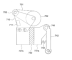
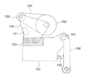
- FIGS. 6 to 8 are views showing modified examples 1 to 3, which are other forms of the swinging portion that supports the support side plate 710 so as to be swingable. Note that the function and operation are in accordance with the description of the transfer device 70 described above.
- FIG. 6 shows a substantially intermediate portion between the connecting portion between the pressing side plate 731 and the supporting member 741 and the connecting portion between the pressing side plate 731 and the supporting side plate 710.
- the pressing side plate 731 is divided into pressing side plates 731a and 731b and pressed.
- An elastic deformation member 732 is provided and connected between the side plates 731a and 731b to constitute the swinging portion. By the elastic deformation of the elastic deformation member 732, the support side plate 710 is supported so as to be able to swing.
- FIG. 7 shows an example in which an elastic deformation member 733 is provided at a connecting portion between the pressing side plate 731 and the supporting side plate 710 and the pressing side plate 731 and the supporting side plate 710 are connected via the elastic deformation member 733 to constitute the swinging portion. is there.
- the support side plate 710 is supported so as to be swingable.
- the elastic deformation member 733 rubber or the like can be used.
- FIG. 8 shows a structure in which a part of the pressing side plate between the connecting portion between the pressing side plate 731 and the supporting member 741 and the connecting portion between the pressing side plate 731 and the supporting side plate 710 can be elastically deformed.
- the swing part is configured.
- a part of the pressing side plate 731 is cut away (D portion in the figure) to reduce the strength and facilitate elastic deformation.
- the image carrier may be a photosensitive drum as described above.
- GH Image forming apparatus main body YS Image reading apparatus P Recording paper 10Y, 10M, 10C, 10K Image forming unit 6 Intermediate transfer belt 61A Backup roller 70 Transfer device 701 Transfer belt 702 Press roller 703 Tension roller 710 Support side plate 711 Connecting member 721 Support member 722 Regulating member 723 Tension spring 731 Press side plate 732, 733 Elastic deformation member 741 Support member 742 Energizing arm 743 Compression spring 744 Cam
Landscapes
- Physics & Mathematics (AREA)
- General Physics & Mathematics (AREA)
- Electrostatic Charge, Transfer And Separation In Electrography (AREA)
- Electrophotography Configuration And Component (AREA)
Abstract
Description
<変形例1>
図6は、押圧側板731と支持部材741との接続部と、押圧側板731と支持側板710との接続部と、の略中間部で、押圧側板731を押圧側板731aと731bに分割し、押圧側板731aと731bとの間に弾性変形部材732を設け接続し、前記揺動部を構成したものである。弾性変形部材732の弾性変形により、支持側板710は揺動可能に支持される。弾性変形部材732としては、ゴム、バネ鋼等を用いることができる。
<変形例2>
図7は、押圧側板731と支持側板710との接続部に弾性変形部材733を設け、弾性変形部材733を介して押圧側板731と支持側板710の接続し、前記揺動部を構成したものである。弾性変形部材733の弾性変形により、支持側板710は揺動可能に支持される。弾性変形部材733としては、ゴム等を用いることができる。
<変形例3>
図8は、押圧側板731と支持部材741との接続部と、押圧側板731と支持側板710との接続部と、の間の、前記押圧側板の一部分を弾性変形可能な構造とすることにより、前記揺動部を構成したものである。図8に示す例では、押圧側板731の一部を切り欠き(図中D部分)、強度を低下させ弾性変形を容易にしている。また、D部分が弾性変形を容易とするために、一般的に知られているバネ鋼を用いることが好ましい。 FIGS. 6 to 8 are views showing modified examples 1 to 3, which are other forms of the swinging portion that supports the
<Modification 1>
FIG. 6 shows a substantially intermediate portion between the connecting portion between the
<Modification 2>
FIG. 7 shows an example in which an
<Modification 3>
FIG. 8 shows a structure in which a part of the pressing side plate between the connecting portion between the
YS 画像読取装置
P 記録紙
10Y、10M、10C、10K 画像形成部
6 中間転写ベルト
61A バックアップローラ
70 転写装置
701 転写ベルト
702 押圧ローラ
703 テンションローラ
710 支持側板
711 連結部材
721 支持部材
722 規制部材
723 引っ張りバネ
731 押圧側板
732、733 弾性変形部材
741 支持部材
742 付勢アーム
743 圧縮バネ
744 カム GH Image forming apparatus main body YS Image reading apparatus
Claims (5)
- トナー像を担持する像担持体と、前記像担持体に形成されたトナー像を記録紙に転写する転写装置を有する画像形成装置であって、
前記転写装置は、
無端状の転写ベルトと、
前記転写ベルトを張架するローラであって、前記像担持体に前記転写ベルトを押圧する押圧ローラを含む複数のローラと、
前記複数のローラを回転自在に支持する、一体化された一対の支持側板と、
前記転写装置の枠体に設けられた支持部材で、前記像担持体と接離する方向に回動可能に支持された一対の押圧側板と、
前記押圧側板に設けられ、前記転写ベルトと前記像担持体の押圧時に、前記支持側板を、前記像担持体に対し揺動可能に支持する揺動部と、
前記転写ベルトが前記像担持体を押圧する方向に前記押圧側板を付勢する付勢部材と、
を有することを特徴とする画像形成装置。 An image forming apparatus comprising: an image carrier that carries a toner image; and a transfer device that transfers the toner image formed on the image carrier to a recording paper.
The transfer device includes:
An endless transfer belt,
A plurality of rollers including a pressure roller that stretches the transfer belt and presses the transfer belt against the image carrier;
A pair of integrated support side plates for rotatably supporting the plurality of rollers;
A pair of pressing side plates supported by a support member provided on a frame of the transfer device so as to be rotatable in a direction contacting and separating from the image carrier;
A swinging portion provided on the pressing side plate, and supporting the support side plate so as to be swingable with respect to the image bearing member when the transfer belt and the image bearing member are pressed;
A biasing member that biases the pressing side plate in a direction in which the transfer belt presses the image carrier;
An image forming apparatus comprising: - 前記揺動部は、前記押圧側板に設けられた前記支持側板を回動可能に支持する第2の支持部材と、前記転写ベルトが前記像担持体を押圧する方向に前記支持側板を付勢する第2の付勢部材とを備えたことを特徴とする請求項1に記載の画像形成装置。 The swinging portion biases the support side plate in a direction in which the transfer belt presses the image carrier, and a second support member that rotatably supports the support side plate provided on the pressure side plate. The image forming apparatus according to claim 1, further comprising a second urging member.
- 前記揺動部は、前記押圧側板と前記支持部材との接続部と、前記押圧側板と前記支持側板との接続部と、の略中間部に、弾性変形部材を備えたことを特徴とする請求項1に記載の画像形成装置。 The rocking portion includes an elastic deformation member at a substantially intermediate portion between a connection portion between the pressing side plate and the support member and a connection portion between the pressing side plate and the support side plate. Item 2. The image forming apparatus according to Item 1.
- 前記揺動部は、前記押圧側板と前記支持側板との接続部に弾性変形部材を備えたことを特徴とする請求項1に記載の画像形成装置。 The image forming apparatus according to claim 1, wherein the swinging portion includes an elastic deformation member at a connection portion between the pressing side plate and the supporting side plate.
- 前記揺動部は、前記押圧側板と前記支持部材との接続部と、前記押圧側板と前記支持側板との接続部と、の間の前記押圧側板の一部分に、弾性変形可能な構造部分を備えたことを特徴とする請求項1に記載の画像形成装置。 The oscillating portion includes an elastically deformable structural portion in a part of the pressing side plate between a connecting portion between the pressing side plate and the supporting member and a connecting portion between the pressing side plate and the supporting side plate. The image forming apparatus according to claim 1.
Priority Applications (4)
| Application Number | Priority Date | Filing Date | Title |
|---|---|---|---|
| US12/810,826 US8417166B2 (en) | 2008-07-11 | 2009-06-25 | Image forming apparatus with a deviation absorbing transfer apparatus |
| JP2010519727A JP5299426B2 (en) | 2008-07-11 | 2009-06-25 | Image forming apparatus |
| CN2009801015069A CN101910956B (en) | 2008-07-11 | 2009-06-25 | Image forming apparatus |
| EP09794322.9A EP2214061B1 (en) | 2008-07-11 | 2009-06-25 | Image forming apparatus |
Applications Claiming Priority (2)
| Application Number | Priority Date | Filing Date | Title |
|---|---|---|---|
| JP2008-181192 | 2008-07-11 | ||
| JP2008181192 | 2008-07-11 |
Publications (1)
| Publication Number | Publication Date |
|---|---|
| WO2010004876A1 true WO2010004876A1 (en) | 2010-01-14 |
Family
ID=41506995
Family Applications (1)
| Application Number | Title | Priority Date | Filing Date |
|---|---|---|---|
| PCT/JP2009/061589 WO2010004876A1 (en) | 2008-07-11 | 2009-06-25 | Image forming apparatus |
Country Status (5)
| Country | Link |
|---|---|
| US (1) | US8417166B2 (en) |
| EP (1) | EP2214061B1 (en) |
| JP (1) | JP5299426B2 (en) |
| CN (1) | CN101910956B (en) |
| WO (1) | WO2010004876A1 (en) |
Cited By (4)
| Publication number | Priority date | Publication date | Assignee | Title |
|---|---|---|---|---|
| JP2012058377A (en) * | 2010-09-07 | 2012-03-22 | Ricoh Co Ltd | Belt device, transfer belt device and image forming apparatus |
| KR20120069508A (en) * | 2010-12-20 | 2012-06-28 | 삼성전자주식회사 | Fusing apparatus and image forming apparatus using the same |
| JP2015163933A (en) * | 2014-01-30 | 2015-09-10 | 株式会社リコー | Pressurizing device, transfer device, and image formation device |
| EP2466390A3 (en) * | 2010-12-20 | 2015-12-23 | Samsung Electronics Co., Ltd. | Fusing device and image forming apparatus using the same |
Families Citing this family (2)
| Publication number | Priority date | Publication date | Assignee | Title |
|---|---|---|---|---|
| CN105645156A (en) * | 2014-11-11 | 2016-06-08 | 沈阳新松机器人自动化股份有限公司 | Automatic paper feeding and cutting mechanism |
| JP6508143B2 (en) * | 2016-08-08 | 2019-05-08 | 京セラドキュメントソリューションズ株式会社 | Transfer unit and image forming apparatus |
Citations (4)
| Publication number | Priority date | Publication date | Assignee | Title |
|---|---|---|---|---|
| JPH04345183A (en) | 1991-05-23 | 1992-12-01 | Konica Corp | Transferring/carrying unit |
| JPH06348148A (en) * | 1993-06-10 | 1994-12-22 | Ricoh Co Ltd | Transfer device |
| JPH10293478A (en) * | 1997-04-18 | 1998-11-04 | Canon Inc | Color image forming device and black-and-white image forming device |
| JP2002148967A (en) * | 2000-11-14 | 2002-05-22 | Fuji Xerox Co Ltd | Image forming device |
Family Cites Families (10)
| Publication number | Priority date | Publication date | Assignee | Title |
|---|---|---|---|---|
| US5169141A (en) * | 1991-09-06 | 1992-12-08 | Xerox Corporation | Floating transfer module mounting |
| US5461461A (en) * | 1992-01-22 | 1995-10-24 | Ricoh Company, Ltd. | Image transferring device and medium separating device for an image forming apparatus |
| JPH06118805A (en) * | 1992-10-06 | 1994-04-28 | Matsushita Electric Ind Co Ltd | Transfer device |
| US5574550A (en) * | 1994-11-10 | 1996-11-12 | Mita Industrial Co., Ltd. | Transfer device for image forming machine |
| JPH08146784A (en) * | 1994-11-21 | 1996-06-07 | Mita Ind Co Ltd | Multi-direction driving mechanism and transfer device for image forming unit using same |
| JP3141316B2 (en) * | 1994-12-02 | 2001-03-05 | 京セラミタ株式会社 | Image forming machine |
| US5983062A (en) * | 1997-04-18 | 1999-11-09 | Canon Kabushiki Kaisha | Image forming apparatus with shifting means to position image transfer unit |
| JP2000284638A (en) * | 1999-03-29 | 2000-10-13 | Seiko Epson Corp | Image forming device |
| JP4345183B2 (en) | 1999-12-20 | 2009-10-14 | ソニー株式会社 | Electric appliances |
| JP4008440B2 (en) * | 2004-08-27 | 2007-11-14 | シャープ株式会社 | Image forming apparatus |
-
2009
- 2009-06-25 CN CN2009801015069A patent/CN101910956B/en active Active
- 2009-06-25 WO PCT/JP2009/061589 patent/WO2010004876A1/en active Application Filing
- 2009-06-25 US US12/810,826 patent/US8417166B2/en active Active
- 2009-06-25 JP JP2010519727A patent/JP5299426B2/en not_active Expired - Fee Related
- 2009-06-25 EP EP09794322.9A patent/EP2214061B1/en active Active
Patent Citations (4)
| Publication number | Priority date | Publication date | Assignee | Title |
|---|---|---|---|---|
| JPH04345183A (en) | 1991-05-23 | 1992-12-01 | Konica Corp | Transferring/carrying unit |
| JPH06348148A (en) * | 1993-06-10 | 1994-12-22 | Ricoh Co Ltd | Transfer device |
| JPH10293478A (en) * | 1997-04-18 | 1998-11-04 | Canon Inc | Color image forming device and black-and-white image forming device |
| JP2002148967A (en) * | 2000-11-14 | 2002-05-22 | Fuji Xerox Co Ltd | Image forming device |
Non-Patent Citations (1)
| Title |
|---|
| See also references of EP2214061A4 * |
Cited By (6)
| Publication number | Priority date | Publication date | Assignee | Title |
|---|---|---|---|---|
| JP2012058377A (en) * | 2010-09-07 | 2012-03-22 | Ricoh Co Ltd | Belt device, transfer belt device and image forming apparatus |
| KR20120069508A (en) * | 2010-12-20 | 2012-06-28 | 삼성전자주식회사 | Fusing apparatus and image forming apparatus using the same |
| JP2012133048A (en) * | 2010-12-20 | 2012-07-12 | Samsung Electronics Co Ltd | Fixing device and image forming apparatus |
| EP2466390A3 (en) * | 2010-12-20 | 2015-12-23 | Samsung Electronics Co., Ltd. | Fusing device and image forming apparatus using the same |
| KR101725890B1 (en) | 2010-12-20 | 2017-04-11 | 에스프린팅솔루션 주식회사 | fusing apparatus and image forming apparatus using the same |
| JP2015163933A (en) * | 2014-01-30 | 2015-09-10 | 株式会社リコー | Pressurizing device, transfer device, and image formation device |
Also Published As
| Publication number | Publication date |
|---|---|
| US8417166B2 (en) | 2013-04-09 |
| EP2214061B1 (en) | 2015-09-02 |
| US20100278568A1 (en) | 2010-11-04 |
| EP2214061A1 (en) | 2010-08-04 |
| CN101910956B (en) | 2013-01-23 |
| JP5299426B2 (en) | 2013-09-25 |
| CN101910956A (en) | 2010-12-08 |
| EP2214061A4 (en) | 2014-08-20 |
| JPWO2010004876A1 (en) | 2012-01-05 |
Similar Documents
| Publication | Publication Date | Title |
|---|---|---|
| US7917074B2 (en) | Fixing device and image forming apparatus | |
| JP5299426B2 (en) | Image forming apparatus | |
| JP6493802B2 (en) | Transfer device and image forming apparatus | |
| CN100511025C (en) | Image heating apparatus | |
| US7606508B2 (en) | Image forming apparatus with a fixing apparatus | |
| JP2014130181A (en) | Belt conveyance device | |
| US20070172265A1 (en) | Image forming device | |
| JP2014134626A (en) | Fixing apparatus and image forming apparatus | |
| JP2007293258A (en) | Image forming apparatus | |
| JP5102573B2 (en) | Fixing apparatus and image forming apparatus | |
| JP4715854B2 (en) | Fixing apparatus and image forming apparatus having the same | |
| JP2009288399A (en) | Fixing device and image-forming device | |
| JP2009282196A (en) | Belt conveyance device and image forming device | |
| US12050415B2 (en) | Reducing bias generated in intermediate transfer belt of an image forming apparatus | |
| JP2004085880A (en) | Image forming apparatus | |
| JP2004094082A (en) | Image forming apparatus | |
| JP2013190571A (en) | Fixing device and image forming apparatus | |
| JP5641893B2 (en) | Paper conveying apparatus and image forming apparatus | |
| JP2004012585A (en) | Belt transport device | |
| JP6775766B2 (en) | Sheet-like body transfer device and image forming device | |
| WO2010016375A1 (en) | Fixing device and image forming device | |
| JP2003295578A (en) | Image forming apparatus | |
| JP2010132440A (en) | Paper ejecting device and image forming device | |
| US8655239B2 (en) | Transfer belt unit and image forming apparatus | |
| JP2013028461A (en) | Image forming apparatus |
Legal Events
| Date | Code | Title | Description |
|---|---|---|---|
| WWE | Wipo information: entry into national phase |
Ref document number: 200980101506.9 Country of ref document: CN |
|
| 121 | Ep: the epo has been informed by wipo that ep was designated in this application |
Ref document number: 09794322 Country of ref document: EP Kind code of ref document: A1 |
|
| WWE | Wipo information: entry into national phase |
Ref document number: 2010519727 Country of ref document: JP |
|
| WWE | Wipo information: entry into national phase |
Ref document number: 2009794322 Country of ref document: EP |
|
| WWE | Wipo information: entry into national phase |
Ref document number: 12810826 Country of ref document: US |
|
| NENP | Non-entry into the national phase |
Ref country code: DE |