WO2009157502A1 - Solar house - Google Patents
Solar house Download PDFInfo
- Publication number
- WO2009157502A1 WO2009157502A1 PCT/JP2009/061563 JP2009061563W WO2009157502A1 WO 2009157502 A1 WO2009157502 A1 WO 2009157502A1 JP 2009061563 W JP2009061563 W JP 2009061563W WO 2009157502 A1 WO2009157502 A1 WO 2009157502A1
- Authority
- WO
- WIPO (PCT)
- Prior art keywords
- solar
- flow path
- air
- heat collection
- house
- Prior art date
Links
- 238000010248 power generation Methods 0.000 claims description 18
- 238000009423 ventilation Methods 0.000 claims description 18
- 239000004065 semiconductor Substances 0.000 claims description 8
- 238000011144 upstream manufacturing Methods 0.000 claims description 4
- XUIMIQQOPSSXEZ-UHFFFAOYSA-N Silicon Chemical compound [Si] XUIMIQQOPSSXEZ-UHFFFAOYSA-N 0.000 claims description 2
- 150000001875 compounds Chemical class 0.000 claims description 2
- 229910052710 silicon Inorganic materials 0.000 claims description 2
- 239000010703 silicon Substances 0.000 claims description 2
- 230000001105 regulatory effect Effects 0.000 abstract 3
- XLYOFNOQVPJJNP-UHFFFAOYSA-N water Substances O XLYOFNOQVPJJNP-UHFFFAOYSA-N 0.000 description 17
- 239000000463 material Substances 0.000 description 10
- 238000005338 heat storage Methods 0.000 description 7
- 239000011232 storage material Substances 0.000 description 5
- 238000006243 chemical reaction Methods 0.000 description 3
- 230000000694 effects Effects 0.000 description 3
- 230000007246 mechanism Effects 0.000 description 3
- 230000004048 modification Effects 0.000 description 3
- 238000012986 modification Methods 0.000 description 3
- 230000004044 response Effects 0.000 description 3
- 239000000758 substrate Substances 0.000 description 3
- 238000001816 cooling Methods 0.000 description 2
- 230000007423 decrease Effects 0.000 description 2
- 238000010586 diagram Methods 0.000 description 2
- 230000007613 environmental effect Effects 0.000 description 2
- 239000011521 glass Substances 0.000 description 2
- 238000000034 method Methods 0.000 description 2
- 230000002265 prevention Effects 0.000 description 2
- 238000010521 absorption reaction Methods 0.000 description 1
- 238000004378 air conditioning Methods 0.000 description 1
- 230000003139 buffering effect Effects 0.000 description 1
- 238000004891 communication Methods 0.000 description 1
- 238000005516 engineering process Methods 0.000 description 1
- 230000002708 enhancing effect Effects 0.000 description 1
- 238000010438 heat treatment Methods 0.000 description 1
- 239000008236 heating water Substances 0.000 description 1
- 239000011810 insulating material Substances 0.000 description 1
- 230000001678 irradiating effect Effects 0.000 description 1
- 238000013021 overheating Methods 0.000 description 1
- 230000009467 reduction Effects 0.000 description 1
- 230000001932 seasonal effect Effects 0.000 description 1
- 239000010409 thin film Substances 0.000 description 1
- 238000002834 transmittance Methods 0.000 description 1
Images


Classifications
-
- H—ELECTRICITY
- H01—ELECTRIC ELEMENTS
- H01L—SEMICONDUCTOR DEVICES NOT COVERED BY CLASS H10
- H01L31/00—Semiconductor devices sensitive to infrared radiation, light, electromagnetic radiation of shorter wavelength or corpuscular radiation and specially adapted either for the conversion of the energy of such radiation into electrical energy or for the control of electrical energy by such radiation; Processes or apparatus specially adapted for the manufacture or treatment thereof or of parts thereof; Details thereof
- H01L31/04—Semiconductor devices sensitive to infrared radiation, light, electromagnetic radiation of shorter wavelength or corpuscular radiation and specially adapted either for the conversion of the energy of such radiation into electrical energy or for the control of electrical energy by such radiation; Processes or apparatus specially adapted for the manufacture or treatment thereof or of parts thereof; Details thereof adapted as photovoltaic [PV] conversion devices
- H01L31/052—Cooling means directly associated or integrated with the PV cell, e.g. integrated Peltier elements for active cooling or heat sinks directly associated with the PV cells
- H01L31/0521—Cooling means directly associated or integrated with the PV cell, e.g. integrated Peltier elements for active cooling or heat sinks directly associated with the PV cells using a gaseous or a liquid coolant, e.g. air flow ventilation, water circulation
-
- F—MECHANICAL ENGINEERING; LIGHTING; HEATING; WEAPONS; BLASTING
- F24—HEATING; RANGES; VENTILATING
- F24S—SOLAR HEAT COLLECTORS; SOLAR HEAT SYSTEMS
- F24S20/00—Solar heat collectors specially adapted for particular uses or environments
- F24S20/60—Solar heat collectors integrated in fixed constructions, e.g. in buildings
- F24S20/67—Solar heat collectors integrated in fixed constructions, e.g. in buildings in the form of roof constructions
-
- H—ELECTRICITY
- H02—GENERATION; CONVERSION OR DISTRIBUTION OF ELECTRIC POWER
- H02S—GENERATION OF ELECTRIC POWER BY CONVERSION OF INFRARED RADIATION, VISIBLE LIGHT OR ULTRAVIOLET LIGHT, e.g. USING PHOTOVOLTAIC [PV] MODULES
- H02S20/00—Supporting structures for PV modules
- H02S20/20—Supporting structures directly fixed to an immovable object
- H02S20/22—Supporting structures directly fixed to an immovable object specially adapted for buildings
- H02S20/23—Supporting structures directly fixed to an immovable object specially adapted for buildings specially adapted for roof structures
-
- Y—GENERAL TAGGING OF NEW TECHNOLOGICAL DEVELOPMENTS; GENERAL TAGGING OF CROSS-SECTIONAL TECHNOLOGIES SPANNING OVER SEVERAL SECTIONS OF THE IPC; TECHNICAL SUBJECTS COVERED BY FORMER USPC CROSS-REFERENCE ART COLLECTIONS [XRACs] AND DIGESTS
- Y02—TECHNOLOGIES OR APPLICATIONS FOR MITIGATION OR ADAPTATION AGAINST CLIMATE CHANGE
- Y02A—TECHNOLOGIES FOR ADAPTATION TO CLIMATE CHANGE
- Y02A30/00—Adapting or protecting infrastructure or their operation
- Y02A30/60—Planning or developing urban green infrastructure
-
- Y—GENERAL TAGGING OF NEW TECHNOLOGICAL DEVELOPMENTS; GENERAL TAGGING OF CROSS-SECTIONAL TECHNOLOGIES SPANNING OVER SEVERAL SECTIONS OF THE IPC; TECHNICAL SUBJECTS COVERED BY FORMER USPC CROSS-REFERENCE ART COLLECTIONS [XRACs] AND DIGESTS
- Y02—TECHNOLOGIES OR APPLICATIONS FOR MITIGATION OR ADAPTATION AGAINST CLIMATE CHANGE
- Y02B—CLIMATE CHANGE MITIGATION TECHNOLOGIES RELATED TO BUILDINGS, e.g. HOUSING, HOUSE APPLIANCES OR RELATED END-USER APPLICATIONS
- Y02B10/00—Integration of renewable energy sources in buildings
- Y02B10/10—Photovoltaic [PV]
-
- Y—GENERAL TAGGING OF NEW TECHNOLOGICAL DEVELOPMENTS; GENERAL TAGGING OF CROSS-SECTIONAL TECHNOLOGIES SPANNING OVER SEVERAL SECTIONS OF THE IPC; TECHNICAL SUBJECTS COVERED BY FORMER USPC CROSS-REFERENCE ART COLLECTIONS [XRACs] AND DIGESTS
- Y02—TECHNOLOGIES OR APPLICATIONS FOR MITIGATION OR ADAPTATION AGAINST CLIMATE CHANGE
- Y02B—CLIMATE CHANGE MITIGATION TECHNOLOGIES RELATED TO BUILDINGS, e.g. HOUSING, HOUSE APPLIANCES OR RELATED END-USER APPLICATIONS
- Y02B10/00—Integration of renewable energy sources in buildings
- Y02B10/20—Solar thermal
-
- Y—GENERAL TAGGING OF NEW TECHNOLOGICAL DEVELOPMENTS; GENERAL TAGGING OF CROSS-SECTIONAL TECHNOLOGIES SPANNING OVER SEVERAL SECTIONS OF THE IPC; TECHNICAL SUBJECTS COVERED BY FORMER USPC CROSS-REFERENCE ART COLLECTIONS [XRACs] AND DIGESTS
- Y02—TECHNOLOGIES OR APPLICATIONS FOR MITIGATION OR ADAPTATION AGAINST CLIMATE CHANGE
- Y02E—REDUCTION OF GREENHOUSE GAS [GHG] EMISSIONS, RELATED TO ENERGY GENERATION, TRANSMISSION OR DISTRIBUTION
- Y02E10/00—Energy generation through renewable energy sources
- Y02E10/40—Solar thermal energy, e.g. solar towers
-
- Y—GENERAL TAGGING OF NEW TECHNOLOGICAL DEVELOPMENTS; GENERAL TAGGING OF CROSS-SECTIONAL TECHNOLOGIES SPANNING OVER SEVERAL SECTIONS OF THE IPC; TECHNICAL SUBJECTS COVERED BY FORMER USPC CROSS-REFERENCE ART COLLECTIONS [XRACs] AND DIGESTS
- Y02—TECHNOLOGIES OR APPLICATIONS FOR MITIGATION OR ADAPTATION AGAINST CLIMATE CHANGE
- Y02E—REDUCTION OF GREENHOUSE GAS [GHG] EMISSIONS, RELATED TO ENERGY GENERATION, TRANSMISSION OR DISTRIBUTION
- Y02E10/00—Energy generation through renewable energy sources
- Y02E10/50—Photovoltaic [PV] energy
Definitions
- the present invention relates to a structure of a building that effectively uses solar energy.
- a technology for improving the comfort and energy saving of a house by utilizing natural energy effectively is known.
- solar houses that use solar energy to generate power, hot water, and the like are known.
- Such a house using natural energy is desirable in that it has an effect of reducing environmental load such as reduction of CO 2 emission.
- This solar system house includes a solar heat collecting part provided on the roof, a heat collecting duct communicating with the solar heat collecting part, and a handling box connected to the heat collecting duct. Inside the handling box are a backflow prevention damper that prevents backflow toward the heat collecting duct, a flow path switching damper that switches communication between the falling duct and the exhaust duct that opens to the outside, and these backflow prevention dampers. And a heat collecting fan provided between the first and second flow path switching dampers.
- a DC (direct current) motor is used as a drive motor for the heat collecting fan of the handling box, and a solar battery and a storage battery connected to the solar battery are connected as a power source.
- Patent Document 2 and Patent Document 3 are given as reference examples of solar houses.
- a solar house that can use solar energy with higher efficiency is desired.
- a technique for improving the efficiency of the solar house by simple means is desired.
- the solar house according to one aspect of the present invention includes a hybrid system that combines a passive solar system and photovoltaic power generation.
- the solar house in another aspect of the present invention, includes a solar cell panel that is disposed with a gap having a predetermined width with respect to the upper surface of the roof, and that forms an air flow path with the upper surface.
- the flow path communicates with outside air on the eaves side.
- the solar house is further disposed in the flow path and has a rectifying member having a longitudinal direction perpendicular to the eaves line, a heat collection chamber connected to an end of the flow path on the ridge side, and storing air, a heat collection chamber and an underfloor And a falling duct connecting the two.
- a silicon-based or compound semiconductor-based solar cell can be used as the solar cell panel.
- the solar cell panel is particularly preferably a tandem type in which an amorphous semiconductor power generation layer and a microcrystalline semiconductor power generation layer are stacked.
- the solar house further includes a blower that sends air in an air path having a flow path upstream, a heat collection chamber, and a downstream under the floor via a falling duct, to the downstream side; It is desirable to provide a wiring system that supplies the power generated by the battery panel to the equipment used in the solar house and the blower.
- the solar house further includes a blower that sends air in an air path having a flow path upstream, a heat collection chamber, and a downstream under the floor via a falling duct, to the downstream side;
- a power conversion unit that converts the power generated by the battery panel into the same characteristics as a public power source that supplies an alternating current to the solar house and links the power to the public power source. It is also desirable to add other solar panels that generate the power to drive the blower.
- the solar house preferably further includes a flow rate adjusting member that variably adjusts the flow rate of air flowing from the flow path into the heat collecting chamber.
- the solar house further has a transparent member that forms a heat collection box flow path through which air flows between the upper surface and the heat collection box provided on the ridge side with respect to the solar cell panel. It is desirable to provide.
- the heat collection chamber is connected to the flow path via the heat collection box flow path.
- the solar house further includes a solar ventilation that is disposed at the top of the solar house, has an internal space surrounded by a transparent member, and has an opening communicating with the external atmosphere. It is desirable to have a box. In this case, the heat collection chamber and the internal space of the solar ventilation box are connected via an openable / closable valve.
- the present invention provides a solar house that can use solar energy with higher efficiency. Moreover, the technique which improves the efficiency of a solar house by a simple means is provided.
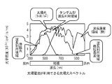
- FIG. 1 is a diagram for explaining the wavelength of an electromagnetic wave that a typical tandem solar cell uses for power generation.
- FIG. 2 is a cross-sectional view of the solar house.
- FIG. 3 is a perspective view showing the roof of the solar house.
- FIG. 4 is a cross-sectional view showing the roof of the solar house.
- FIG. 5 is a plan view showing the roof of the solar house.
- FIG. 6 is a plan view of the current plate.
- FIG. 7 shows a hot water supply mechanism.
- a tandem solar cell is used.
- a tandem solar cell is formed by stacking a solar power generation layer formed of an amorphous semiconductor and a solar power generation layer formed of a microcrystalline semiconductor.
- the tandem solar cell is relatively low cost, but has high cost performance as described below.
- FIG. 1 is a diagram for explaining the wavelength of an electromagnetic wave that a typical tandem solar cell uses for power generation.
- the thin-film (amorphous) power generation layer generates power using sunlight in a relatively short wavelength region.
- the microcrystalline power generation layer generates power using sunlight in a wavelength region having a longer wavelength as a peak. Since these tandem solar cells are stacked, solar energy can be converted into electric energy with high efficiency except for a region having a longer wavelength than a certain extent.
- a highly efficient solar house is realized by providing means for effectively using solar energy in the long wavelength region.
- FIG. 2 is a cross-sectional view of the solar house in the present embodiment.
- the solar house includes a roof material 2 that forms an inclined roof.
- a solar cell 4 is installed on the roofing material 2.
- the solar cell 4 is disposed through a gap having a predetermined width with respect to the upper surface of the roofing material 2.
- the solar cell 4 is one in which panel-like tandem solar cell modules are spread in a predetermined power generation region.
- the power generation area extends, for example, to the vicinity of the eaves of the roof. More preferably, the power generation area covers most of the area between the south facing roof eave and the heat collection chamber that slopes down to the south.
- the electric power generated by the solar cell 4 is supplied to the living space 30 and the like via a wiring system and a power conversion device for linking with a commercial power source.
- the air flow path 6 through which air flows is formed by the gap between the upper surface of the roofing material 2 and the lower surface of the solar cell 4.
- the air flow path 6 is closed at the end in the eaves line direction.
- An air inlet 8 is formed at the end of the air flow path 6 on the eaves side. It is desirable that the extension of the air introduction port 8 in the eave line direction is at least as long as the extension of the power generation region in the eave line direction.
- the air inlet 8 is provided with a bird net that prevents birds from entering.
- the air flow path 6 is connected to the heat collection chamber 12 on the building side.
- the heat collection chamber 12 forms a space for buffering air supplied from the air flow path 6 in the vicinity of the roof of the solar house.
- the heat collection chamber 12 is connected to the heat exchanger 14 directly or by a duct. Part of the heat of the air collected in the heat collection chamber 12 can be used for the purpose of heating water through the heat exchanger 14.
- a solar ventilation box 16 is installed on the heat collection chamber 12, that is, near the top of the solar house.
- the solar ventilation box 16 has an internal space for storing air.
- the internal space is connected to the heat collection chamber 12 via the switching valve 15.
- the forced exhaust fan 10 is used when the natural ventilation of the solar ventilation box 16 is weak.
- the solar ventilation box 16 is provided with a heat insulating material on the floor surface side, a frame other than the floor surface and a transparent member supported by the frame (the transmittance of electromagnetic wave energy in the visible light band is arranged in the solar cell 4. It is a greenhouse formed by a member larger than the area, preferably a transparent glass plate), and efficiently converts solar energy into thermal energy of air in the interior space.
- the solar ventilation box 16 has an opening 17 communicating with the outside atmosphere.
- the solar ventilation box 16 further has an air introduction path communicating with the interior of the living space 30.
- a dedicated duct may be provided as the air introduction path.
- the heat collection chamber 12 is connected to the falling duct 20 via the switching valve 18.
- the falling duct 20 is a duct extending in the vertical direction, and connects the heat collection chamber 12 and the underfloor 24.
- a fan 19 is installed at an appropriate location to collect air from the air flow path 6 of the roof to the heat collecting chamber 12 and guide the air through the falling duct 20 to the underfloor 24.
- the underfloor 24 is a space formed under the floor of the living space 30 of the solar house.
- the underfloor 24 is formed of a member having a large heat storage capacity such as a concrete floor at the bottom. Further, a heat storage material 26 having a large heat storage capacity is disposed under the floor 24. The air accumulated in the underfloor 24 is supplied to the living space 30 through the ventilation openings 28 provided in the floor 22.
- the heat storage material 26 is, for example, a concrete lump. It is desirable that each of the heat storage materials 26 is a heat storage material that is independently placed on a cart with casters so that the arrangement can be easily changed according to the characteristics of the air circulation and temperature distribution under the floor.
- FIG. 3 is a perspective view showing the roof of the solar house.
- a rectifying plate 32 is provided in the air flow path 6.
- the rectifying plate 32 is formed so that the air flow direction of the air flow path 6 is aligned from the eaves side to the ridge side.
- the rectifying plate 32 extends in a direction perpendicular to the eaves line of the roof as a longitudinal direction, and divides the space between the upper surface of the roof material 2 and the lower surface of the solar cell 4 into a plurality of sections in the eave line direction. It is a member.
- air having a low temperature outside the solar house is introduced into the air flow path 6 from the air inlet 8 during the daytime in summer.
- This introduction is performed in a natural circulation through the solar ventilation box by moving from the eaves side to the building side by convection based on the air inside the air flow path 6 being heated by the heat supplied from the sun. .
- the amount of air introduced from the air inlet 8 may be increased by additionally installing the fan 10.
- the energy of the sunlight irradiating the roof is converted into electric energy by the solar cells 4 and 34.
- the electric energy of the solar cell 34 is used as a power source for driving the fans 10 and 19.
- the fans 10 and 19 driven by a DC power source are employed, they can be driven using the power of the solar cell 4 without necessarily performing DC / AC conversion.
- This electrical energy is further converted into desired characteristics for use by residents. Typically, it is converted into electric power having the same characteristics as the commercial power source and used in conjunction with the commercial power source.
- the tandem solar cell 4 has a small amount of absorption of sunlight in the wavelength region centered on infrared rays. Therefore, it is possible to supply the energy of solar rays centering on infrared rays to the air flow path 6. This energy raises the temperature of the air flowing through the air flow path 6. The air whose temperature has risen is supplied to the heat collection chamber 12.
- the air around the solar house is continuously supplied to the air flow path 6 from the eave side end. This air cools the lower surface of the solar cell 4. Therefore, a decrease in power generation efficiency due to an increase in the operating temperature of the solar cell 4 is suppressed.
- the rectifying plate 32 allows the inflowing air to flow uniformly over the entire roof.
- the flow of natural circulation generated by the temperature difference between the eaves and the building increases. Therefore, a large amount of warmed air can be supplied to the heat collection chamber 12. Further, the effect of cooling the solar cell 4 is improved. Moreover, even when the temperature difference between the eaves side and the building side is small, air can be guided to the building side by natural circulation.
- the heat of the air accumulated in the heat collection chamber 12 heats the water via the heat exchanger 14 to generate hot water. This hot water is used for hot water supply.
- the air in the heat collection chamber 12 is supplied to the floor 24 by the fan 19.
- the warm air supplied to the underfloor 24 warms the concrete that forms the bottom of the underfloor 24 and the heat storage material 26 placed under the underfloor 24, and heat is accumulated in the underfloor 24. This accumulated heat warms the floor 22.
- the air under the floor 24 is supplied to the living space 30 through the ventilation openings 28 to warm the living space 30.
- the solar house further has a mechanism for supplying the heat of the solar ventilation box 16 under the floor.
- the heated air inside the solar ventilation box 16 is supplied to the underfloor 24 via the falling duct 20, further enhancing the heating effect.
- outside air introduced from the air inlet 8 passes through the air flow path 6 and is supplied to the heat collection chamber 12.
- the switching valve 18 that connects the heat collecting chamber 12 and the falling duct 20 is closed. Warmed air is released from the heat collection chamber 12 to the outside air by opening a switching valve (not shown).
- the forced exhaust fan 10 is used when the natural ventilation of the solar ventilation box 16 is weak. Since overheating of the roofing material 2 is suppressed by the air flow in the air flow path 6, solar heat entering the living space 30 is reduced.
- the temperature of the roof on which the solar cells 4 are placed decreases due to radiative cooling.
- the outside air introduced from the air introduction port 8 is cooled in the air flow path 6 and supplied to the underfloor 24 via the heat collection chamber 12 and the falling duct 20. Therefore, cold heat is stored in the floor 24.
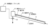
- FIG. 4 is a cross-sectional view showing the roof of a solar house in a modification of the present embodiment.
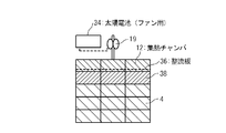
- FIG. 5 is a corresponding plan view (viewed from above in the vertical direction).
- a heat collection box 38 is further provided.
- the heat collection box 38 is arranged on the ridge side of the power generation region of the solar cell 4 (downstream side in the main flow direction of air in the air flow path 6).
- a member glass or the like
- an air flow path connected to the air flow path 6 between the solar cell 4 and the roof material 2 is formed.
- the heat collection chamber 12 is connected to an air flow path 6 formed by a gap between the solar cell 4 and the roof material 2 via a heat collection box 38.
- a rectifying plate 36 is installed between the heat collecting chamber 12 and the heat collecting box 38.
- the rectifying plate 36 is a flow rate adjusting member that variably adjusts the flow rate of air flowing into the heat collection chamber 12.
- the air flow path 6 is provided with a rectifying plate 32 similar to that shown in FIG.
- the rectifying plate 32 is preferably extended to the inside of the heat collection box 38.
- a fan that supplies air to the heat collection chamber 12, the underfloor 24, and the like exemplified by the fans 10 and 19 in FIG. 2 is driven.
- Another solar cell 34 that generates electric power for the purpose is installed.
- the electric power generated by the solar cell 4 is converted into AC electric power having the same characteristics as that of the commercial power source, and used as a power source for the air conditioning of the living space 30 and home appliances.
- the solar cell 34 is used as a DC power source for a fan driven by a DC motor. Dividing the power supply in this way improves the independence of air circulation based on the natural energy of the solar house.
- FIG. 6 is a plan view of the current plate 36 (viewed from above in the vertical direction while being fixed to the heat collection box 38 and the heat collection chamber 12).
- the rectifying plate 36 includes a substrate and a rectifying blade 40 that can rotate around an axis 40 perpendicular to the substrate.
- the substrate is fixed in parallel to the roofing material 2.
- a plurality of rectifying blades 40 are arranged side by side in the ridge line direction. The rectifying blade 40 does not rotate depending on the air supplied from the air flow path 6 and is attached to the shaft 42 with such a hardness that the angle around the shaft can be manually adjusted.
- Such a solar house can adjust the opening degree of the flow path of the circulating air by adjusting the angle around the shaft 42 of the rectifying blade 40 of the rectifying plate 36. As a result, the amount of circulating air supplied to the heat collection chamber 12 can be adjusted. When a large amount of circulating air is required, the opening of the rectifying plate 36 is adjusted to be large. When a small amount of circulating air having a higher temperature is required, the opening of the rectifying plate 36 is adjusted to be small. In this way, the circulating air can be easily adjusted according to the environmental conditions where the solar house is installed, seasonal variations, and the needs of residents.
- FIG. 7 shows a hot water supply mechanism using the heat of the air accumulated in the heat collecting chamber 12.
- the warm air accumulated in the internal space of the heat collection chamber 12 is supplied to the high temperature side flow path of the heat exchanger 44 by the fan 19.
- a heat medium such as water is supplied to the low temperature side flow path of the heat exchanger 44.
- the heat medium is supplied to the high temperature side flow path of the heat exchanger 52 installed in the first tank 46.
- the heat medium circulated between the first tank 46 and the heat exchanger 44 by the circulation pump 54 forms a primary circulation system. Water is supplied from the water supply pipe 50 to the internal space of the first tank 46. Heat of the heat medium of the primary circulation system is supplied to this water via the heat exchanger 52.
- the water in the internal space of the first tank 46 is supplied to the second tank 48 via an electromagnetic valve whose opening degree is controlled in response to an external electric signal.
- the second tank 48 is a heat pump water heater tank.
- the electromagnetic valve is controlled in response to the start, and the hot water in the first tank 46 is supplied to the second tank 48.
- the heat pump operates in response to the temperature, and the temperature of the hot water supplied from the second tank 48 is automatically within a predetermined temperature range. Keeped.
Abstract
A solar house is provided with solar cell panels arranged on the upper surface of a roof at intervals with a predetermined width and forming an air flow path between the upper surface and the solar cell panels. The flow path communicates on the eaves side with outside air. The solar house is also provided with flow regulating members having a longitudinal direction perpendicular to an eaves line and mounted in the flow path, a heat collecting chamber connected to that end of the flow path which is on the ridge side and accumulating air, and a descending duct for interconnecting the heat collecting chamber and an underfloor space. Flow of air flowing into the flow path from the eaves and heated by heat on the lower surface side of the solar cell panels is efficiently collected in the heat collecting chamber after being regulated by the flow regulating plates and can be supplied to the underfloor space.
Description
本発明は、太陽エネルギーを有効に活用する建造物の機構に関する。
The present invention relates to a structure of a building that effectively uses solar energy.
自然エネルギーを有効に活用することにより住宅の快適性や省エネルギー性を向上する技術が知られている。特に、太陽エネルギーを利用して発電、給湯などを行うソーラーハウスが知られている。このような自然エネルギーを利用した住宅は、CO2排出量の削減など環境への負荷を低減する効果を有する点で望ましい。
A technology for improving the comfort and energy saving of a house by utilizing natural energy effectively is known. In particular, solar houses that use solar energy to generate power, hot water, and the like are known. Such a house using natural energy is desirable in that it has an effect of reducing environmental load such as reduction of CO 2 emission.
太陽エネルギーを利用したソーラーシステムハウスの一例が特許文献1に示されている。このソーラーシステムハウスは、屋根に設けられた太陽熱集熱部と、この太陽熱集熱部に連通する集熱用のダクトと、集熱用のダクトに接続されたハンドリングボックスとを備える。このハンドリングボックスの内部には、集熱用のダクトの側へ逆流防止を行う逆流防止ダンパーと、立下りダクトおよび外へ開口する排気ダクトとの連通を切り換える流路切換えダンパーと、これら逆流防止ダンパーと流路切換えダンパーとの間に設ける集熱用ファンが配設される。ハンドリングボックスの集熱用ファンの駆動モータはDC(直流)モータを使用し、太陽電池およびこの太陽電池に接続する蓄電池が電源として接続される。
An example of a solar system house using solar energy is disclosed in Patent Document 1. This solar system house includes a solar heat collecting part provided on the roof, a heat collecting duct communicating with the solar heat collecting part, and a handling box connected to the heat collecting duct. Inside the handling box are a backflow prevention damper that prevents backflow toward the heat collecting duct, a flow path switching damper that switches communication between the falling duct and the exhaust duct that opens to the outside, and these backflow prevention dampers. And a heat collecting fan provided between the first and second flow path switching dampers. A DC (direct current) motor is used as a drive motor for the heat collecting fan of the handling box, and a solar battery and a storage battery connected to the solar battery are connected as a power source.
ソーラーハウスの参考例として、特許文献2と特許文献3を挙げる。
Patent Document 2 and Patent Document 3 are given as reference examples of solar houses.
太陽エネルギーをより高い効率で利用することのできるソーラーハウスが望まれる。
また、簡易な手段でソーラーハウスの効率を向上させる技術が望まれる。 A solar house that can use solar energy with higher efficiency is desired.
In addition, a technique for improving the efficiency of the solar house by simple means is desired.
また、簡易な手段でソーラーハウスの効率を向上させる技術が望まれる。 A solar house that can use solar energy with higher efficiency is desired.
In addition, a technique for improving the efficiency of the solar house by simple means is desired.
本発明の一側面におけるソーラーハウスは、パッシブソーラーシステムと太陽光発電を組み合わせたハイブリッドシステムを備える。
The solar house according to one aspect of the present invention includes a hybrid system that combines a passive solar system and photovoltaic power generation.
本発明の他の側面において、ソーラーハウスは、屋根の上面に対して所定の幅の隙間を介して配置され、上面との間に空気の流路を形成する太陽電池パネルを備える。流路は軒側において外気と連通する。ソーラーハウスは更に、流路に配置され、軒線と直交する長手方向を有する整流部材と、流路の棟側の端部に接続され空気を蓄積する集熱チャンバと、集熱チャンバと床下とを接続する立ち下りダクトとを備える。
In another aspect of the present invention, the solar house includes a solar cell panel that is disposed with a gap having a predetermined width with respect to the upper surface of the roof, and that forms an air flow path with the upper surface. The flow path communicates with outside air on the eaves side. The solar house is further disposed in the flow path and has a rectifying member having a longitudinal direction perpendicular to the eaves line, a heat collection chamber connected to an end of the flow path on the ridge side, and storing air, a heat collection chamber and an underfloor And a falling duct connecting the two.
本発明の更に他の側面において、太陽電池パネルとして、シリコン系、または化合物半導体系の太陽電池を使用することができる。太陽電池パネルは、非晶質半導体の発電層と微結晶質半導体の発電層とが積層されたタンデム型であることが特に望ましい。
In yet another aspect of the present invention, a silicon-based or compound semiconductor-based solar cell can be used as the solar cell panel. The solar cell panel is particularly preferably a tandem type in which an amorphous semiconductor power generation layer and a microcrystalline semiconductor power generation layer are stacked.
本発明の更に他の側面において、ソーラーハウスは、更に、流路を上流とし、集熱チャンバ、立下りダクトを介して床下を下流とする空気経路内の空気を下流側に送る送風機と、太陽電池パネルが生成した電力を当該ソーラーハウスで使用される機器と送風機とに供給する配線系統とを備えることが望ましい。
In yet another aspect of the present invention, the solar house further includes a blower that sends air in an air path having a flow path upstream, a heat collection chamber, and a downstream under the floor via a falling duct, to the downstream side; It is desirable to provide a wiring system that supplies the power generated by the battery panel to the equipment used in the solar house and the blower.
本発明の更に他の側面において、ソーラーハウスは、更に、流路を上流とし、集熱チャンバ、立下りダクトを介して床下を下流とする空気経路内の空気を下流側に送る送風機と、太陽電池パネルが生成した電力を、当該ソーラーハウスに交流電流を供給する公衆電源と同じ特性に変換して公衆電源と連係させる電力変換部とを備える。送風機を駆動する電力を生成する他の太陽電池パネルを追加することも望ましい。
In yet another aspect of the present invention, the solar house further includes a blower that sends air in an air path having a flow path upstream, a heat collection chamber, and a downstream under the floor via a falling duct, to the downstream side; A power conversion unit that converts the power generated by the battery panel into the same characteristics as a public power source that supplies an alternating current to the solar house and links the power to the public power source. It is also desirable to add other solar panels that generate the power to drive the blower.
本発明の更に他の側面において、ソーラーハウスは、更に、流路から集熱チャンバに流入する空気の流量を可変的に調整する流量調整部材を備えることが望ましい。
In still another aspect of the present invention, the solar house preferably further includes a flow rate adjusting member that variably adjusts the flow rate of air flowing from the flow path into the heat collecting chamber.
本発明の更に他の側面において、ソーラーハウスは、更に、上面との間に空気が流れる集熱ボックス流路を形成する透明部材を有し太陽電池パネルに対して棟側に設けられる集熱ボックスを備えることが望ましい。この場合、集熱チャンバは集熱ボックス流路を介して流路に接続される。
In yet another aspect of the present invention, the solar house further has a transparent member that forms a heat collection box flow path through which air flows between the upper surface and the heat collection box provided on the ridge side with respect to the solar cell panel. It is desirable to provide. In this case, the heat collection chamber is connected to the flow path via the heat collection box flow path.
本発明の更に他の側面において、ソーラーハウスは、更に、当該ソーラーハウスの最上部に配置され、透明部材によって囲われた内部空間を有し、外部の大気と連通する開口部を有するソーラーベンチレーションボックスを備えることが望ましい。この場合、集熱チャンバとソーラーベンチレーションボックスの内部空間は開閉可能な弁を介して接続される。
In still another aspect of the present invention, the solar house further includes a solar ventilation that is disposed at the top of the solar house, has an internal space surrounded by a transparent member, and has an opening communicating with the external atmosphere. It is desirable to have a box. In this case, the heat collection chamber and the internal space of the solar ventilation box are connected via an openable / closable valve.
本発明により、太陽エネルギーをより高い効率で利用することのできるソーラーハウスが提供される。また、簡易な手段でソーラーハウスの効率を向上させる技術が提供される。
The present invention provides a solar house that can use solar energy with higher efficiency. Moreover, the technique which improves the efficiency of a solar house by a simple means is provided.
本発明に関する上述の及びその他の目的、利点、特徴は、いくつかの実施形態に関して、添付図面と併せて以下の記載から更に明らかとなるであろう。その添付図面には下記のものが含まれる。
図1は、典型的なタンデム型太陽電池が発電に利用する電磁波の波長を説明するための図である。
図2は、ソーラーハウスの断面図である。
図3は、ソーラーハウスの屋根を示す斜視図である。
図4は、ソーラーハウスの屋根を示す断面図である。
図5は、ソーラーハウスの屋根を示す平面図である。
図6は、整流板の平面図である。
図7は、給湯機構を示す。
The foregoing and other objects, advantages, and features of the present invention will become more apparent from the following description, taken in conjunction with the accompanying drawings, for several embodiments. The accompanying drawings include the following.
FIG. 1 is a diagram for explaining the wavelength of an electromagnetic wave that a typical tandem solar cell uses for power generation. FIG. 2 is a cross-sectional view of the solar house. FIG. 3 is a perspective view showing the roof of the solar house. FIG. 4 is a cross-sectional view showing the roof of the solar house. FIG. 5 is a plan view showing the roof of the solar house. FIG. 6 is a plan view of the current plate. FIG. 7 shows a hot water supply mechanism.
以下、図面を参照して本発明を実施するための最良の形態について説明する。
Hereinafter, the best mode for carrying out the present invention will be described with reference to the drawings.
本実施の形態におけるソーラーハウスでは、タンデム型太陽電池が用いられる。タンデム型太陽電池は、非晶質半導体により形成された太陽光発電層と、微結晶半導体により形成された太陽光発電層が積層されることにより形成される。タンデム型太陽電池は、比較的低コストだが、以下に説明するように高いコストパフォーマンスを有する。
In the solar house in this embodiment, a tandem solar cell is used. A tandem solar cell is formed by stacking a solar power generation layer formed of an amorphous semiconductor and a solar power generation layer formed of a microcrystalline semiconductor. The tandem solar cell is relatively low cost, but has high cost performance as described below.
図1は、典型的なタンデム型太陽電池が発電に利用する電磁波の波長を説明するための図である。薄膜系(非晶質)の発電層は、比較的短い波長領域の太陽光を利用して電力を生成する。それに対して、微結晶系の発電層は、より長い波長をピークとする波長領域の太陽光を利用して電力を生成する。タンデム型の太陽電池は、これらが積層されているために、ある程度以上に長波長の領域を除いて、太陽エネルギーを高効率で電気エネルギーに変換することができる。
FIG. 1 is a diagram for explaining the wavelength of an electromagnetic wave that a typical tandem solar cell uses for power generation. The thin-film (amorphous) power generation layer generates power using sunlight in a relatively short wavelength region. On the other hand, the microcrystalline power generation layer generates power using sunlight in a wavelength region having a longer wavelength as a peak. Since these tandem solar cells are stacked, solar energy can be converted into electric energy with high efficiency except for a region having a longer wavelength than a certain extent.
しかし、ある程度長波長の領域(図1で900nm付近の領域)では、一般的なタンデム型太陽電池によって太陽エネルギーを高い効率で電気エネルギーに変換することは難しい。本実施の形態においては、この長波長領域の太陽エネルギーを有効に利用する手段を設けることにより、高効率なソーラーハウスが実現される。
However, it is difficult to convert solar energy into high-efficiency electric energy with a general tandem solar cell in a region with a relatively long wavelength (region near 900 nm in FIG. 1). In the present embodiment, a highly efficient solar house is realized by providing means for effectively using solar energy in the long wavelength region.
図2は、本実施の形態におけるソーラーハウスの断面図である。ソーラーハウスは、傾斜した屋根を形成する屋根材2を備える。屋根材2の上に、太陽電池4が設置される。太陽電池4は、屋根材2の上面に対して所定の幅の隙間を介して配置される。太陽電池4は、パネル状のタンデム型太陽電池モジュールが所定の発電領域内に敷き詰められたものである。その発電領域は、たとえば屋根の軒付近まで延長する。より望ましくは、発電領域は、南側に下がるように傾斜する南向きの屋根の軒と集熱チャンバとの間の領域の大部分を覆う。太陽電池4が生成する電力は、配線系統と、商用電源と連係するための電力変換装置などを介して、居住空間30などに供給される。
FIG. 2 is a cross-sectional view of the solar house in the present embodiment. The solar house includes a roof material 2 that forms an inclined roof. A solar cell 4 is installed on the roofing material 2. The solar cell 4 is disposed through a gap having a predetermined width with respect to the upper surface of the roofing material 2. The solar cell 4 is one in which panel-like tandem solar cell modules are spread in a predetermined power generation region. The power generation area extends, for example, to the vicinity of the eaves of the roof. More preferably, the power generation area covers most of the area between the south facing roof eave and the heat collection chamber that slopes down to the south. The electric power generated by the solar cell 4 is supplied to the living space 30 and the like via a wiring system and a power conversion device for linking with a commercial power source.
屋根材2の上面と太陽電池4の下面との間の隙間により、空気が流れる空気流路6が形成される。空気流路6は、軒線方向の端部において閉じている。空気流路6の軒側の端部には空気導入口8が形成される。空気導入口8の軒線方向の延長は、少なくとも発電領域の軒線方向の延長と同じ程度であることが望ましい。空気導入口8には、鳥の侵入を妨げる防鳥網が設置される。
The air flow path 6 through which air flows is formed by the gap between the upper surface of the roofing material 2 and the lower surface of the solar cell 4. The air flow path 6 is closed at the end in the eaves line direction. An air inlet 8 is formed at the end of the air flow path 6 on the eaves side. It is desirable that the extension of the air introduction port 8 in the eave line direction is at least as long as the extension of the power generation region in the eave line direction. The air inlet 8 is provided with a bird net that prevents birds from entering.
空気流路6は、棟側において集熱チャンバ12に接続される。集熱チャンバ12は、ソーラーハウスの屋根の棟付近において、空気流路6から供給される空気をバッファするための空間を形成する。集熱チャンバ12は熱交換器14に直接またはダクトにより接続される。集熱チャンバ12に集められた空気の熱の一部は、熱交換器14を介して水を加熱する等の目的に利用することができる。
The air flow path 6 is connected to the heat collection chamber 12 on the building side. The heat collection chamber 12 forms a space for buffering air supplied from the air flow path 6 in the vicinity of the roof of the solar house. The heat collection chamber 12 is connected to the heat exchanger 14 directly or by a duct. Part of the heat of the air collected in the heat collection chamber 12 can be used for the purpose of heating water through the heat exchanger 14.
集熱チャンバ12の上に、すなわちソーラーハウスの頂上付近に、ソーラーベンチレーションボックス16が設置される。ソーラーベンチレーションボックス16は、空気を蓄積する内部空間を有する。その内部空間は、切替弁15を介して集熱チャンバ12と接続される。また、強制排気用ファン10はソーラーベンチレーションボックス16の自然換気力が弱い場合に使用する。ソーラーベンチレーションボックス16は、床面側に断熱材が敷かれ、床面以外は枠とその枠によって支持される透明部材(可視光帯における電磁波のエネルギーの透過率が太陽電池4の配置された領域よりも大きい部材であり、望ましくは透明なガラス板)によって形成される温室であり、太陽エネルギーを効率的に内部空間の空気の熱エネルギーに変換する。
A solar ventilation box 16 is installed on the heat collection chamber 12, that is, near the top of the solar house. The solar ventilation box 16 has an internal space for storing air. The internal space is connected to the heat collection chamber 12 via the switching valve 15. The forced exhaust fan 10 is used when the natural ventilation of the solar ventilation box 16 is weak. The solar ventilation box 16 is provided with a heat insulating material on the floor surface side, a frame other than the floor surface and a transparent member supported by the frame (the transmittance of electromagnetic wave energy in the visible light band is arranged in the solar cell 4. It is a greenhouse formed by a member larger than the area, preferably a transparent glass plate), and efficiently converts solar energy into thermal energy of air in the interior space.
ソーラーベンチレーションボックス16は、外部の大気に連通する開口17を有する。ソーラーベンチレーションボックス16は更に、居住空間30の内部と連通する空気導入経路を有する。この空気導入経路として専用のダクトを設けてもよい。
The solar ventilation box 16 has an opening 17 communicating with the outside atmosphere. The solar ventilation box 16 further has an air introduction path communicating with the interior of the living space 30. A dedicated duct may be provided as the air introduction path.
集熱チャンバ12は、切替弁18を介して立下りダクト20に接続される。立下りダクト20は、鉛直方向に延設されるダクトであり、集熱チャンバ12と床下24とを接続する。屋根の空気流路6から集熱チャンバ12に空気を集め、その空気を立下りダクト20を介して床下24に導くために、適切な場所にファン19が設置される。
The heat collection chamber 12 is connected to the falling duct 20 via the switching valve 18. The falling duct 20 is a duct extending in the vertical direction, and connects the heat collection chamber 12 and the underfloor 24. A fan 19 is installed at an appropriate location to collect air from the air flow path 6 of the roof to the heat collecting chamber 12 and guide the air through the falling duct 20 to the underfloor 24.
床下24は、ソーラーハウスの居住空間30の床の下に形成される空間である。床下24は、その底部がコンクリートの床など蓄熱容量の大きい部材により形成される。床下24には更に、蓄熱容量の大きい蓄熱材26が配置される。床下24に蓄積された空気は、床22に設けられた通風口28を介して居住空間30に供給される。
The underfloor 24 is a space formed under the floor of the living space 30 of the solar house. The underfloor 24 is formed of a member having a large heat storage capacity such as a concrete floor at the bottom. Further, a heat storage material 26 having a large heat storage capacity is disposed under the floor 24. The air accumulated in the underfloor 24 is supplied to the living space 30 through the ventilation openings 28 provided in the floor 22.
蓄熱材26は、例えばコンクリート塊である。蓄熱材26は、床下の空気循環及び温度分布の特性に合わせて容易に配置を変更できるように、各々が独立にキャスター付きの台車に乗せられた蓄熱材であることが望ましい。
The heat storage material 26 is, for example, a concrete lump. It is desirable that each of the heat storage materials 26 is a heat storage material that is independently placed on a cart with casters so that the arrangement can be easily changed according to the characteristics of the air circulation and temperature distribution under the floor.
図3は、ソーラーハウスの屋根を示す斜視図である。説明の便宜上、発電領域の太陽電池4の一部のモジュールが取り外された状態を図示している。空気流路6に整流板32が設けられる。整流板32は、空気流路6の空気の流れ方向が軒側から棟側に揃うように形成される。例えば整流板32は、屋根の軒線に対して直交する方向を長手方向として延設され、屋根材2の上面と太陽電池4の下面との隙間の空間を軒線方向に複数の区画に仕切る部材である。
FIG. 3 is a perspective view showing the roof of the solar house. For convenience of explanation, a state in which some modules of the solar cell 4 in the power generation region are removed is illustrated. A rectifying plate 32 is provided in the air flow path 6. The rectifying plate 32 is formed so that the air flow direction of the air flow path 6 is aligned from the eaves side to the ridge side. For example, the rectifying plate 32 extends in a direction perpendicular to the eaves line of the roof as a longitudinal direction, and divides the space between the upper surface of the roof material 2 and the lower surface of the solar cell 4 into a plurality of sections in the eave line direction. It is a member.
以上の構成を備えるソーラーハウスにおいて、夏の昼間、ソーラーハウスの外部の温度の低い空気が、空気導入口8から空気流路6に導入される。この導入は、空気流路6の内部の空気が太陽から供給される熱によって暖められることに基づく対流によって軒側から棟側に移動することによりソーラーベンチレーションボックスを介して自然循環的に行われる。追加的にファン10を設置することによって空気導入口8から導入される空気量を増加させてもよい。
In the solar house having the above configuration, air having a low temperature outside the solar house is introduced into the air flow path 6 from the air inlet 8 during the daytime in summer. This introduction is performed in a natural circulation through the solar ventilation box by moving from the eaves side to the building side by convection based on the air inside the air flow path 6 being heated by the heat supplied from the sun. . The amount of air introduced from the air inlet 8 may be increased by additionally installing the fan 10.
屋根に照射する太陽光線のエネルギーは、太陽電池4、34によって電気エネルギーに変換される。このうち太陽電池34の電気エネルギーは、ファン10、19を駆動するための電源に使用される。直流電源で駆動されるファン10、19を採用すると、必ずしも直流交流変換を行わずに太陽電池4の電力を用いてそれらを駆動することができる。この電気エネルギーは更に、所望の特性に電力変換されて居住者の利用に供される。典型的には商用電源と同じ特性の電力に変換されて商用電源と連係して使用される。
The energy of the sunlight irradiating the roof is converted into electric energy by the solar cells 4 and 34. Among these, the electric energy of the solar cell 34 is used as a power source for driving the fans 10 and 19. When the fans 10 and 19 driven by a DC power source are employed, they can be driven using the power of the solar cell 4 without necessarily performing DC / AC conversion. This electrical energy is further converted into desired characteristics for use by residents. Typically, it is converted into electric power having the same characteristics as the commercial power source and used in conjunction with the commercial power source.
タンデム型の太陽電池4は、赤外線を中心とする波長領域の太陽光線の吸収量が少ない。そのため、赤外線を中心とする太陽光線のエネルギーを空気流路6に供給することが可能である。このエネルギーにより、空気流路6を流れる空気の温度が上昇する。温度が上昇した空気は、集熱チャンバ12に供給される。
The tandem solar cell 4 has a small amount of absorption of sunlight in the wavelength region centered on infrared rays. Therefore, it is possible to supply the energy of solar rays centering on infrared rays to the air flow path 6. This energy raises the temperature of the air flowing through the air flow path 6. The air whose temperature has risen is supplied to the heat collection chamber 12.
空気流路6には軒側の端部からソーラーハウス周辺の空気が連続的に供給される。この空気は、太陽電池4の下面を冷却する。そのため、太陽電池4の動作温度の上昇に起因する発電効率の低下が抑制される。
The air around the solar house is continuously supplied to the air flow path 6 from the eave side end. This air cools the lower surface of the solar cell 4. Therefore, a decrease in power generation efficiency due to an increase in the operating temperature of the solar cell 4 is suppressed.
整流板32により、流入する空気が屋根全体に均一に流れるようにする。特に軒側と棟側の温度差により発生する自然循環の流量が増加する。そのため、多量の暖められた空気を集熱チャンバ12に供給することができる。また太陽電池4を冷却する効果が向上する。また軒側と棟側の温度差が小さいときであっても自然循環によって空気を棟側に導くことができる。
The rectifying plate 32 allows the inflowing air to flow uniformly over the entire roof. In particular, the flow of natural circulation generated by the temperature difference between the eaves and the building increases. Therefore, a large amount of warmed air can be supplied to the heat collection chamber 12. Further, the effect of cooling the solar cell 4 is improved. Moreover, even when the temperature difference between the eaves side and the building side is small, air can be guided to the building side by natural circulation.
集熱チャンバ12に蓄積された空気の熱は、熱交換器14を介して水を加熱して温水を生成する。この温水は、給湯に用いられる。
The heat of the air accumulated in the heat collection chamber 12 heats the water via the heat exchanger 14 to generate hot water. This hot water is used for hot water supply.
集熱チャンバ12内の空気は、ファン19によって床下24に供給される。床下24に供給されたこの暖かい空気は、床下24の底を形成するコンクリートと、床下24に置かれた蓄熱材26を暖め、床下24に熱が蓄積される。この蓄積された熱は、床22を暖める。床下24の空気は、通風口28を介して居住空間30に供給されて居住空間30を暖める。
The air in the heat collection chamber 12 is supplied to the floor 24 by the fan 19. The warm air supplied to the underfloor 24 warms the concrete that forms the bottom of the underfloor 24 and the heat storage material 26 placed under the underfloor 24, and heat is accumulated in the underfloor 24. This accumulated heat warms the floor 22. The air under the floor 24 is supplied to the living space 30 through the ventilation openings 28 to warm the living space 30.
ソーラーハウスは更に、ソーラーベンチレーションボックス16の熱を床下に供給する機構を有することが望ましい。この場合、切替弁15を切り替えることにより、ソーラーベンチレーションボックス16の内部の温められた空気が立下りダクト20を介して床下24に供給され、さらに暖房効果を高める。
It is desirable that the solar house further has a mechanism for supplying the heat of the solar ventilation box 16 under the floor. In this case, by switching the switching valve 15, the heated air inside the solar ventilation box 16 is supplied to the underfloor 24 via the falling duct 20, further enhancing the heating effect.
夏季の昼間には、空気導入口8から導入された外気は、空気流路6を通り、集熱チャンバ12に供給される。集熱チャンバ12と立下りダクト20とを接続する切替弁18は閉じられる。集熱チャンバ12からは、暖められた空気が図示しない切替弁を開放することにより外気に放出される。また、強制排気用ファン10はソーラーベンチレーションボックス16の自然換気力が弱い場合に使用する。空気流路6の空気の流れによって、屋根材2の過熱が抑えられるため、居住空間30に入り込む日射熱が減少する。
During the summer daytime, outside air introduced from the air inlet 8 passes through the air flow path 6 and is supplied to the heat collection chamber 12. The switching valve 18 that connects the heat collecting chamber 12 and the falling duct 20 is closed. Warmed air is released from the heat collection chamber 12 to the outside air by opening a switching valve (not shown). The forced exhaust fan 10 is used when the natural ventilation of the solar ventilation box 16 is weak. Since overheating of the roofing material 2 is suppressed by the air flow in the air flow path 6, solar heat entering the living space 30 is reduced.
夏季の夜間には、放射冷却により太陽電池4を載せた屋根の温度が下がる。空気導入口8から導入された外気は、空気流路6において冷却され、集熱チャンバ12、立下りダクト20を介して床下24に供給される。そのため床下24に冷熱が蓄えられる。
In the summer night, the temperature of the roof on which the solar cells 4 are placed decreases due to radiative cooling. The outside air introduced from the air introduction port 8 is cooled in the air flow path 6 and supplied to the underfloor 24 via the heat collection chamber 12 and the falling duct 20. Therefore, cold heat is stored in the floor 24.
図4は、本実施の形態の変形例におけるソーラーハウスの屋根を示す断面図である。図5は対応する平面図(鉛直方向上側から見た図)である。この変形例においては、更に集熱ボックス38が設けられる。集熱ボックス38は、太陽電池4の発電領域の棟側(空気流路6における空気の主な流れ方向の下流側)に配置される。集熱ボックス38においては、太陽電池4と概ね同一平面上に、太陽光に対して広い波長領域で透明な部材(ガラスなど)が配置される。その透明部材と屋根材2との間には、太陽電池4と屋根材2との間の空気流路6と接続する空気流路が形成される。集熱チャンバ12は、集熱ボックス38を介して、太陽電池4と屋根材2の隙間が形成する空気流路6に接続する。集熱チャンバ12と集熱ボックス38との間に、フランジによって整流板36が設置される。整流板36は、集熱チャンバ12に流入する空気の流量を可変的に調整する流量調整部材である。空気流路6には図3に示されたものと同様の整流板32が設置される。整流板32は集熱ボックス38の内部まで延設されることが望ましい。
FIG. 4 is a cross-sectional view showing the roof of a solar house in a modification of the present embodiment. FIG. 5 is a corresponding plan view (viewed from above in the vertical direction). In this modification, a heat collection box 38 is further provided. The heat collection box 38 is arranged on the ridge side of the power generation region of the solar cell 4 (downstream side in the main flow direction of air in the air flow path 6). In the heat collection box 38, a member (glass or the like) that is transparent in a wide wavelength region with respect to sunlight is disposed on the same plane as the solar cell 4. Between the transparent member and the roof material 2, an air flow path connected to the air flow path 6 between the solar cell 4 and the roof material 2 is formed. The heat collection chamber 12 is connected to an air flow path 6 formed by a gap between the solar cell 4 and the roof material 2 via a heat collection box 38. Between the heat collecting chamber 12 and the heat collecting box 38, a rectifying plate 36 is installed by a flange. The rectifying plate 36 is a flow rate adjusting member that variably adjusts the flow rate of air flowing into the heat collection chamber 12. The air flow path 6 is provided with a rectifying plate 32 similar to that shown in FIG. The rectifying plate 32 is preferably extended to the inside of the heat collection box 38.
本変形例においては更に、空気流路6を形成する太陽電池4の他に、図2のファン10、19に例示される、集熱チャンバ12及び床下24等に空気を供給するファンを駆動するための電力を生成する他の太陽電池34が設置される。こうした用途のために図2に示された主たる太陽電池4の電力を用いることも可能であるが、別途太陽電池34を設けることも好ましい。この場合、太陽電池4の生成する電力は商用電源と特性の同じ交流電力に変換されて、居住空間30の空調や家庭電化製品などの電源として用いられる。一方、太陽電池34は直流モーターによって駆動するファンの直流電源として使用される。このように電源を分けると、ソーラーハウスの自然エネルギーに基づく空気循環の自立性が向上する。
In this modification, in addition to the solar cell 4 that forms the air flow path 6, a fan that supplies air to the heat collection chamber 12, the underfloor 24, and the like exemplified by the fans 10 and 19 in FIG. 2 is driven. Another solar cell 34 that generates electric power for the purpose is installed. Although it is possible to use the power of the main solar cell 4 shown in FIG. 2 for such applications, it is also preferable to provide a separate solar cell 34. In this case, the electric power generated by the solar cell 4 is converted into AC electric power having the same characteristics as that of the commercial power source, and used as a power source for the air conditioning of the living space 30 and home appliances. On the other hand, the solar cell 34 is used as a DC power source for a fan driven by a DC motor. Dividing the power supply in this way improves the independence of air circulation based on the natural energy of the solar house.
図6は、整流板36の平面図(集熱ボックス38と集熱チャンバ12に対して固定された状態で鉛直方向の上から見た図)である。整流板36は、基板と、その基板に対して垂直な軸40のまわりに回転可能な整流羽根40とを備える。基板は、屋根材2に対して平行に固定される。整流羽根40は、棟線方向に複数並んで配置される。この整流羽根40は、空気流路6から供給される空気によっては回転せず、手動で軸まわりの角度を調節できる程度の固さで軸42に取り付けられる。
FIG. 6 is a plan view of the current plate 36 (viewed from above in the vertical direction while being fixed to the heat collection box 38 and the heat collection chamber 12). The rectifying plate 36 includes a substrate and a rectifying blade 40 that can rotate around an axis 40 perpendicular to the substrate. The substrate is fixed in parallel to the roofing material 2. A plurality of rectifying blades 40 are arranged side by side in the ridge line direction. The rectifying blade 40 does not rotate depending on the air supplied from the air flow path 6 and is attached to the shaft 42 with such a hardness that the angle around the shaft can be manually adjusted.
こうしたソーラーハウスは、整流板36の整流羽根40の軸42まわりの角度を調節することにより、循環空気の流路の開度を調整することができる。その結果、集熱チャンバ12に供給される循環空気の量を調整することができる。多量の循環空気が求められる場合は、整流板36の開度が大きくなるように調整される。少量だがより温度の高い循環空気が求められる場合は、整流板36の開度が小さくなるように調整される。このようにして、ソーラーハウスの設置されている環境の条件、季節変動、居住者のニーズに応じて循環空気を容易に調整することができる。
Such a solar house can adjust the opening degree of the flow path of the circulating air by adjusting the angle around the shaft 42 of the rectifying blade 40 of the rectifying plate 36. As a result, the amount of circulating air supplied to the heat collection chamber 12 can be adjusted. When a large amount of circulating air is required, the opening of the rectifying plate 36 is adjusted to be large. When a small amount of circulating air having a higher temperature is required, the opening of the rectifying plate 36 is adjusted to be small. In this way, the circulating air can be easily adjusted according to the environmental conditions where the solar house is installed, seasonal variations, and the needs of residents.
図7は、集熱チャンバ12に蓄積された空気の熱を利用した給湯機構を示す。集熱チャンバ12の内部空間に蓄積された暖かい空気は、ファン19により熱交換器44の高温側流路に供給される。熱交換器44の低温側流路には、水などの熱媒体が供給される。その熱媒体は、第1タンク46に設置される熱交換器52の高温側流路に供給される。循環ポンプ54によって第1タンク46と熱交換器44との間で循環する熱媒体は、一次循環系統を形成する。第1タンク46の内部空間には、給水管50から水が供給される。この水に、熱交換器52を介して一次循環系統の熱媒体の熱が供給される。
FIG. 7 shows a hot water supply mechanism using the heat of the air accumulated in the heat collecting chamber 12. The warm air accumulated in the internal space of the heat collection chamber 12 is supplied to the high temperature side flow path of the heat exchanger 44 by the fan 19. A heat medium such as water is supplied to the low temperature side flow path of the heat exchanger 44. The heat medium is supplied to the high temperature side flow path of the heat exchanger 52 installed in the first tank 46. The heat medium circulated between the first tank 46 and the heat exchanger 44 by the circulation pump 54 forms a primary circulation system. Water is supplied from the water supply pipe 50 to the internal space of the first tank 46. Heat of the heat medium of the primary circulation system is supplied to this water via the heat exchanger 52.
第1タンク46の内部空間の水は、外部からの電気信号に応答して開度が制御される電磁弁を介して、第2タンク48に供給される。第2タンク48は、ヒートポンプ給湯器のタンクである。居住者の操作やタイマ設定に応じて給湯機能の利用が開始された時点で、その開始に応答して電磁弁が制御されて第1タンク46の温水が第2タンク48に供給される。深夜電力利用時において第2タンク46の水の温度が低い場合には、その温度に応答してヒートポンプが稼働し、第2タンク48から供給される温水の温度が所定の温度範囲に自動的にキープされる。
The water in the internal space of the first tank 46 is supplied to the second tank 48 via an electromagnetic valve whose opening degree is controlled in response to an external electric signal. The second tank 48 is a heat pump water heater tank. When the use of the hot water supply function is started according to the operation of the resident or the timer setting, the electromagnetic valve is controlled in response to the start, and the hot water in the first tank 46 is supplied to the second tank 48. When the temperature of the water in the second tank 46 is low when using midnight power, the heat pump operates in response to the temperature, and the temperature of the hot water supplied from the second tank 48 is automatically within a predetermined temperature range. Keeped.
以上、いくつかの実施形態によって本発明を説明したが、これらの実施の諸形態は単に発明を説明するために挙げられたものであり請求の範囲の内容を限定するために参照されるべきでないことは、当業者には明らかである。
Although the present invention has been described with reference to several embodiments, these embodiments are merely described for explaining the present invention and should not be referred to in order to limit the content of the claims. This will be apparent to those skilled in the art.
この出願は、2008年6月27日に出願された日本出願特願2008-169510号を基礎とする優先権を主張し、その開示の全てをここに取り込む。
This application claims priority based on Japanese Patent Application No. 2008-169510 filed on June 27, 2008, the entire disclosure of which is incorporated herein.
Claims (7)
- 太陽電池パネルと、
パッシブソーラーシステムとを具備し、
前記太陽電池は、屋根の上面に対して所定の幅の隙間を介して配置され、前記上面との間に空気の流路を形成し、前記流路は軒側において外気と連通し、
前記パッシブソーラーシステムは、
前記流路に配置され、軒線と直交する方向を長手方向として延設される整流部材と、
前記流路の棟側の端部に接続され空気を蓄積する集熱チャンバと、
前記集熱チャンバと床下とを接続する立ち下りダクトとを備える
ソーラーハウス。 A solar panel,
With a passive solar system,
The solar cell is disposed through a gap having a predetermined width with respect to the upper surface of the roof, and forms a flow path of air between the upper surface, and the flow path communicates with outside air on the eaves side,
The passive solar system is
A rectifying member disposed in the flow path and extending in a direction perpendicular to the eaves line as a longitudinal direction;
A heat collection chamber connected to the ridge side end of the flow path and storing air;
A solar house comprising a falling duct connecting the heat collection chamber and the underfloor. - 請求の範囲1に記載されたソーラーハウスであって、
前記太陽電池パネルは、非晶質半導体の発電層と微結晶質半導体の発電層とが積層されたタンデム、またはシリコン系または化合物半導体系である
ソーラーハウス。 A solar house according to claim 1,
The solar cell panel is a tandem in which an amorphous semiconductor power generation layer and a microcrystalline semiconductor power generation layer are stacked, or a silicon-based or compound semiconductor-based solar house. - 請求の範囲1または2に記載されたソーラーハウスであって、
更に、前記流路を上流とし、前記集熱チャンバ、前記立下りダクトを介して前記床下を下流とする経路内の空気を下流側に送る送風機と、
前記太陽電池パネルが生成した電力を当該ソーラーハウスで使用される機器と前記送風機とに供給する配線系統
とを具備するソーラーハウス。 A solar house according to claim 1 or 2,
Furthermore, the blower that sends the air in the path having the flow path upstream, the heat collection chamber, and the downstream under the floor through the falling duct to the downstream side,
The solar house which comprises the wiring system which supplies the electric power which the said solar cell panel produced | generated to the apparatus used in the said solar house, and the said air blower. - 請求の範囲1または2に記載されたソーラーハウスであって、
更に、前記流路を上流とし、前記集熱チャンバ、前記立下りダクトを介して前記床下を下流とする経路内の空気を下流側に送る送風機と、
前記太陽電池パネルが生成した電力を、当該ソーラーハウスに交流電流を供給する公衆電源と同じ特性に変換して前記公衆電源と連係させる電力変換部と、
前記送風機を駆動する電力を生成する他の太陽電池パネル
とを具備するソーラーハウス。 A solar house according to claim 1 or 2,
Furthermore, the blower that sends the air in the path having the flow path upstream, the heat collection chamber, and the downstream under the floor through the falling duct to the downstream side,
A power converter that converts the power generated by the solar cell panel into the same characteristics as a public power source that supplies an alternating current to the solar house and links the public power source;
A solar house comprising: another solar cell panel that generates electric power for driving the blower. - 請求の範囲1から4のいずれかに記載されたソーラーハウスであって、
更に、前記流路から前記集熱チャンバに流入する空気の流量を可変的に調整する流量調整部材
を具備するソーラーハウス。 A solar house according to any one of claims 1 to 4,
Furthermore, the solar house which comprises the flow volume adjustment member which adjusts the flow volume of the air which flows into the said heat collection chamber from the said flow path variably. - 請求の範囲1から5のいずれかに記載されたソーラーハウスであって、
更に、前記上面との間に空気が流れる集熱ボックス流路を形成する透明部材を有し前記太陽電池パネルに対して棟側に設けられる集熱ボックスを具備し、
前記集熱チャンバは前記集熱ボックス流路を介して前記流路に接続される
ソーラーハウス。 A solar house according to any one of claims 1 to 5,
Furthermore, it comprises a heat collection box provided on the ridge side with respect to the solar cell panel having a transparent member that forms a heat collection box flow path through which air flows between the upper surface,
The solar heat collection chamber is connected to the flow path through the heat collection box flow path. - 請求の範囲1から6のいずれかに記載されたソーラーハウスであって、
更に、当該ソーラーハウスの最上部に配置され、透明部材によって囲われた内部空間を有し、外部の大気と連通する開口部を有するソーラーベンチレーションボックスを具備し、
前記集熱チャンバと前記ソーラーベンチレーションボックスの内部空間は開閉可能な弁を介して接続される
ソーラーハウス。 A solar house according to any one of claims 1 to 6,
Furthermore, the solar house is disposed at the top of the solar house, has an internal space surrounded by a transparent member, and has a solar ventilation box having an opening communicating with the outside atmosphere,
A solar house, wherein the heat collection chamber and the internal space of the solar ventilation box are connected via an openable / closable valve.
Applications Claiming Priority (2)
| Application Number | Priority Date | Filing Date | Title |
|---|---|---|---|
| JP2008-169510 | 2008-06-27 | ||
| JP2008169510A JP4980304B2 (en) | 2008-06-27 | 2008-06-27 | Solar house |
Publications (1)
| Publication Number | Publication Date |
|---|---|
| WO2009157502A1 true WO2009157502A1 (en) | 2009-12-30 |
Family
ID=41444566
Family Applications (1)
| Application Number | Title | Priority Date | Filing Date |
|---|---|---|---|
| PCT/JP2009/061563 WO2009157502A1 (en) | 2008-06-27 | 2009-06-25 | Solar house |
Country Status (2)
| Country | Link |
|---|---|
| JP (1) | JP4980304B2 (en) |
| WO (1) | WO2009157502A1 (en) |
Cited By (2)
| Publication number | Priority date | Publication date | Assignee | Title |
|---|---|---|---|---|
| JP2014202453A (en) * | 2013-04-09 | 2014-10-27 | ミサワホーム株式会社 | Building floor heating system |
| CN113251696A (en) * | 2020-02-12 | 2021-08-13 | 青岛海尔新能源电器有限公司 | Heat pump unit, heat pump water heater and control method thereof |
Families Citing this family (2)
| Publication number | Priority date | Publication date | Assignee | Title |
|---|---|---|---|---|
| JP5319644B2 (en) * | 2010-11-01 | 2013-10-16 | 三菱電機株式会社 | Energy management system and program |
| JP2018029429A (en) * | 2016-08-17 | 2018-02-22 | 未来工業株式会社 | Power generating system |
Citations (9)
| Publication number | Priority date | Publication date | Assignee | Title |
|---|---|---|---|---|
| JPS57172333U (en) * | 1981-04-22 | 1982-10-29 | ||
| JPS57193140U (en) * | 1981-05-30 | 1982-12-07 | ||
| JPH04100705U (en) * | 1991-01-28 | 1992-08-31 | ||
| JPH085159A (en) * | 1994-06-24 | 1996-01-12 | Sekisui Chem Co Ltd | Solar energy utilizing roof |
| JPH0861725A (en) * | 1994-08-26 | 1996-03-08 | Fujita Corp | Ventilating tower |
| JPH09273775A (en) * | 1996-04-03 | 1997-10-21 | Ig Tech Res Inc | House |
| JP2001041591A (en) * | 1997-10-04 | 2001-02-16 | Yoshiro Nakamatsu | Photothermal material high efficiency energy apparatus |
| JP2002235955A (en) * | 2001-02-07 | 2002-08-23 | Om Kenkyusho:Kk | Solar system house |
| JP2006183933A (en) * | 2004-12-27 | 2006-07-13 | Sanyo Electric Co Ltd | Photovoltaic system |
Family Cites Families (1)
| Publication number | Priority date | Publication date | Assignee | Title |
|---|---|---|---|---|
| JP3209692B2 (en) * | 1996-12-03 | 2001-09-17 | 積水化学工業株式会社 | Ventilation structure behind solar cell module juxtaposition body and ventilation structure of building provided with the structure |
-
2008
- 2008-06-27 JP JP2008169510A patent/JP4980304B2/en not_active Expired - Fee Related
-
2009
- 2009-06-25 WO PCT/JP2009/061563 patent/WO2009157502A1/en active Application Filing
Patent Citations (9)
| Publication number | Priority date | Publication date | Assignee | Title |
|---|---|---|---|---|
| JPS57172333U (en) * | 1981-04-22 | 1982-10-29 | ||
| JPS57193140U (en) * | 1981-05-30 | 1982-12-07 | ||
| JPH04100705U (en) * | 1991-01-28 | 1992-08-31 | ||
| JPH085159A (en) * | 1994-06-24 | 1996-01-12 | Sekisui Chem Co Ltd | Solar energy utilizing roof |
| JPH0861725A (en) * | 1994-08-26 | 1996-03-08 | Fujita Corp | Ventilating tower |
| JPH09273775A (en) * | 1996-04-03 | 1997-10-21 | Ig Tech Res Inc | House |
| JP2001041591A (en) * | 1997-10-04 | 2001-02-16 | Yoshiro Nakamatsu | Photothermal material high efficiency energy apparatus |
| JP2002235955A (en) * | 2001-02-07 | 2002-08-23 | Om Kenkyusho:Kk | Solar system house |
| JP2006183933A (en) * | 2004-12-27 | 2006-07-13 | Sanyo Electric Co Ltd | Photovoltaic system |
Cited By (3)
| Publication number | Priority date | Publication date | Assignee | Title |
|---|---|---|---|---|
| JP2014202453A (en) * | 2013-04-09 | 2014-10-27 | ミサワホーム株式会社 | Building floor heating system |
| CN113251696A (en) * | 2020-02-12 | 2021-08-13 | 青岛海尔新能源电器有限公司 | Heat pump unit, heat pump water heater and control method thereof |
| CN113251696B (en) * | 2020-02-12 | 2022-12-13 | 青岛海尔新能源电器有限公司 | Heat pump unit, heat pump water heater and control method thereof |
Also Published As
| Publication number | Publication date |
|---|---|
| JP4980304B2 (en) | 2012-07-18 |
| JP2010007989A (en) | 2010-01-14 |
Similar Documents
| Publication | Publication Date | Title |
|---|---|---|
| JP7405813B2 (en) | solar roofing system | |
| JP3690602B2 (en) | Pneumatic solar system | |
| ES2648213T3 (en) | Roof support with structurally integrated solar collector | |
| EP2904334B1 (en) | Solar air heating / cooling system | |
| JP3163802U (en) | Hybrid structure using sunlight and solar heat in buildings | |
| US8375936B2 (en) | Method and system for operating a thermal solar system using a reverse motor configuration | |
| KR101385776B1 (en) | cooling and heating system with composition energy control | |
| US20110209742A1 (en) | Method and Structure for a Cool Roof by Using a Plenum Structure | |
| CN103245018A (en) | Split evaporating air-conditioning unit with sun-shading, generating and soundproofing functions | |
| EP2429002A1 (en) | Device provided with solar cells | |
| JP3797685B2 (en) | Building heating system | |
| JP4980304B2 (en) | Solar house | |
| KR20140104073A (en) | The eco-friendly multi-functional heat recovery hvac system | |
| Wang et al. | Field experimental investigation of a multifunctional curved CIGS photovoltaic/thermal (PV/T) roof system for traditional Chinese buildings | |
| CN109962262A (en) | Temperature control mechanism and fuel cell with temperature control mechanism | |
| US8360050B1 (en) | Method and system for operating a thermal solar system using a reverse motor configuration for thawing ice | |
| CN111895572A (en) | Residence fresh air system control method and system | |
| KR101914095B1 (en) | Shoes drying apparatus using pvt module | |
| KR20170030398A (en) | Movable solar heat blower for leisure with the solar heat collection portion | |
| CN208487677U (en) | A kind of photovoltaic and photothermal integrated machine system | |
| CN114562764A (en) | Building chimney effect natural ventilation strengthening system and method | |
| CN208720337U (en) | Photo-thermal architecture-integral heating system | |
| JP2649906B2 (en) | Solar heat collector | |
| JP2002076407A (en) | Photovoltaic power generator utilizing outdoor machine of air-conditioner | |
| WO2018191833A1 (en) | Greenhouse cultivation device employing heat generated by variable-frequency drive or inverter |
Legal Events
| Date | Code | Title | Description |
|---|---|---|---|
| 121 | Ep: the epo has been informed by wipo that ep was designated in this application |
Ref document number: 09770212 Country of ref document: EP Kind code of ref document: A1 |
|
| NENP | Non-entry into the national phase |
Ref country code: DE |
|
| 122 | Ep: pct application non-entry in european phase |
Ref document number: 09770212 Country of ref document: EP Kind code of ref document: A1 |