WO2009145288A1 - TiO2を含有するシリカガラスおよびそれを用いたリソグラフィ用光学部材 - Google Patents
TiO2を含有するシリカガラスおよびそれを用いたリソグラフィ用光学部材 Download PDFInfo
- Publication number
- WO2009145288A1 WO2009145288A1 PCT/JP2009/059844 JP2009059844W WO2009145288A1 WO 2009145288 A1 WO2009145288 A1 WO 2009145288A1 JP 2009059844 W JP2009059844 W JP 2009059844W WO 2009145288 A1 WO2009145288 A1 WO 2009145288A1
- Authority
- WO
- WIPO (PCT)
- Prior art keywords
- glass
- tio
- sio
- temperature
- hydrogen
- Prior art date
- Legal status (The legal status is an assumption and is not a legal conclusion. Google has not performed a legal analysis and makes no representation as to the accuracy of the status listed.)
- Ceased
Links
Images

Classifications
-
- B—PERFORMING OPERATIONS; TRANSPORTING
- B82—NANOTECHNOLOGY
- B82Y—SPECIFIC USES OR APPLICATIONS OF NANOSTRUCTURES; MEASUREMENT OR ANALYSIS OF NANOSTRUCTURES; MANUFACTURE OR TREATMENT OF NANOSTRUCTURES
- B82Y40/00—Manufacture or treatment of nanostructures
-
- B—PERFORMING OPERATIONS; TRANSPORTING
- B82—NANOTECHNOLOGY
- B82Y—SPECIFIC USES OR APPLICATIONS OF NANOSTRUCTURES; MEASUREMENT OR ANALYSIS OF NANOSTRUCTURES; MANUFACTURE OR TREATMENT OF NANOSTRUCTURES
- B82Y10/00—Nanotechnology for information processing, storage or transmission, e.g. quantum computing or single electron logic
-
- C—CHEMISTRY; METALLURGY
- C03—GLASS; MINERAL OR SLAG WOOL
- C03B—MANUFACTURE, SHAPING, OR SUPPLEMENTARY PROCESSES
- C03B19/00—Other methods of shaping glass
- C03B19/14—Other methods of shaping glass by gas- or vapour- phase reaction processes
- C03B19/1453—Thermal after-treatment of the shaped article, e.g. dehydrating, consolidating, sintering
-
- C—CHEMISTRY; METALLURGY
- C03—GLASS; MINERAL OR SLAG WOOL
- C03C—CHEMICAL COMPOSITION OF GLASSES, GLAZES OR VITREOUS ENAMELS; SURFACE TREATMENT OF GLASS; SURFACE TREATMENT OF FIBRES OR FILAMENTS MADE FROM GLASS, MINERALS OR SLAGS; JOINING GLASS TO GLASS OR OTHER MATERIALS
- C03C3/00—Glass compositions
- C03C3/04—Glass compositions containing silica
- C03C3/06—Glass compositions containing silica with more than 90% silica by weight, e.g. quartz
-
- C—CHEMISTRY; METALLURGY
- C03—GLASS; MINERAL OR SLAG WOOL
- C03C—CHEMICAL COMPOSITION OF GLASSES, GLAZES OR VITREOUS ENAMELS; SURFACE TREATMENT OF GLASS; SURFACE TREATMENT OF FIBRES OR FILAMENTS MADE FROM GLASS, MINERALS OR SLAGS; JOINING GLASS TO GLASS OR OTHER MATERIALS
- C03C4/00—Compositions for glass with special properties
- C03C4/0085—Compositions for glass with special properties for UV-transmitting glass
-
- G—PHYSICS
- G03—PHOTOGRAPHY; CINEMATOGRAPHY; ANALOGOUS TECHNIQUES USING WAVES OTHER THAN OPTICAL WAVES; ELECTROGRAPHY; HOLOGRAPHY
- G03F—PHOTOMECHANICAL PRODUCTION OF TEXTURED OR PATTERNED SURFACES, e.g. FOR PRINTING, FOR PROCESSING OF SEMICONDUCTOR DEVICES; MATERIALS THEREFOR; ORIGINALS THEREFOR; APPARATUS SPECIALLY ADAPTED THEREFOR
- G03F1/00—Originals for photomechanical production of textured or patterned surfaces, e.g., masks, photo-masks, reticles; Mask blanks or pellicles therefor; Containers specially adapted therefor; Preparation thereof
- G03F1/22—Masks or mask blanks for imaging by radiation of 100nm or shorter wavelength, e.g. X-ray masks, extreme ultraviolet [EUV] masks; Preparation thereof
- G03F1/24—Reflection masks; Preparation thereof
-
- G—PHYSICS
- G03—PHOTOGRAPHY; CINEMATOGRAPHY; ANALOGOUS TECHNIQUES USING WAVES OTHER THAN OPTICAL WAVES; ELECTROGRAPHY; HOLOGRAPHY
- G03F—PHOTOMECHANICAL PRODUCTION OF TEXTURED OR PATTERNED SURFACES, e.g. FOR PRINTING, FOR PROCESSING OF SEMICONDUCTOR DEVICES; MATERIALS THEREFOR; ORIGINALS THEREFOR; APPARATUS SPECIALLY ADAPTED THEREFOR
- G03F1/00—Originals for photomechanical production of textured or patterned surfaces, e.g., masks, photo-masks, reticles; Mask blanks or pellicles therefor; Containers specially adapted therefor; Preparation thereof
- G03F1/60—Substrates
-
- C—CHEMISTRY; METALLURGY
- C03—GLASS; MINERAL OR SLAG WOOL
- C03B—MANUFACTURE, SHAPING, OR SUPPLEMENTARY PROCESSES
- C03B2201/00—Type of glass produced
- C03B2201/06—Doped silica-based glasses
- C03B2201/07—Impurity concentration specified
- C03B2201/075—Hydroxyl ion (OH)
-
- C—CHEMISTRY; METALLURGY
- C03—GLASS; MINERAL OR SLAG WOOL
- C03B—MANUFACTURE, SHAPING, OR SUPPLEMENTARY PROCESSES
- C03B2201/00—Type of glass produced
- C03B2201/06—Doped silica-based glasses
- C03B2201/20—Doped silica-based glasses doped with non-metals other than boron or fluorine
- C03B2201/23—Doped silica-based glasses doped with non-metals other than boron or fluorine doped with hydroxyl groups
-
- C—CHEMISTRY; METALLURGY
- C03—GLASS; MINERAL OR SLAG WOOL
- C03B—MANUFACTURE, SHAPING, OR SUPPLEMENTARY PROCESSES
- C03B2201/00—Type of glass produced
- C03B2201/06—Doped silica-based glasses
- C03B2201/30—Doped silica-based glasses doped with metals, e.g. Ga, Sn, Sb, Pb or Bi
- C03B2201/40—Doped silica-based glasses doped with metals, e.g. Ga, Sn, Sb, Pb or Bi doped with transition metals other than rare earth metals, e.g. Zr, Nb, Ta or Zn
- C03B2201/42—Doped silica-based glasses doped with metals, e.g. Ga, Sn, Sb, Pb or Bi doped with transition metals other than rare earth metals, e.g. Zr, Nb, Ta or Zn doped with titanium
-
- C—CHEMISTRY; METALLURGY
- C03—GLASS; MINERAL OR SLAG WOOL
- C03C—CHEMICAL COMPOSITION OF GLASSES, GLAZES OR VITREOUS ENAMELS; SURFACE TREATMENT OF GLASS; SURFACE TREATMENT OF FIBRES OR FILAMENTS MADE FROM GLASS, MINERALS OR SLAGS; JOINING GLASS TO GLASS OR OTHER MATERIALS
- C03C2201/00—Glass compositions
- C03C2201/06—Doped silica-based glasses
- C03C2201/20—Doped silica-based glasses containing non-metals other than boron or halide
- C03C2201/21—Doped silica-based glasses containing non-metals other than boron or halide containing molecular hydrogen
-
- C—CHEMISTRY; METALLURGY
- C03—GLASS; MINERAL OR SLAG WOOL
- C03C—CHEMICAL COMPOSITION OF GLASSES, GLAZES OR VITREOUS ENAMELS; SURFACE TREATMENT OF GLASS; SURFACE TREATMENT OF FIBRES OR FILAMENTS MADE FROM GLASS, MINERALS OR SLAGS; JOINING GLASS TO GLASS OR OTHER MATERIALS
- C03C2201/00—Glass compositions
- C03C2201/06—Doped silica-based glasses
- C03C2201/30—Doped silica-based glasses containing metals
- C03C2201/40—Doped silica-based glasses containing metals containing transition metals other than rare earth metals, e.g. Zr, Nb, Ta or Zn
- C03C2201/42—Doped silica-based glasses containing metals containing transition metals other than rare earth metals, e.g. Zr, Nb, Ta or Zn containing titanium
-
- G—PHYSICS
- G21—NUCLEAR PHYSICS; NUCLEAR ENGINEERING
- G21K—HANDLING OF PARTICLES OR IONISING RADIATION NOT OTHERWISE PROVIDED FOR; IRRADIATION DEVICES; GAMMA RAY OR X-RAY MICROSCOPES
- G21K2201/00—Arrangements for handling radiation or particles
- G21K2201/06—Arrangements for handling radiation or particles using diffractive, refractive or reflecting elements
- G21K2201/067—Construction details
Definitions
- the present invention relates to silica glass containing TiO 2 (hereinafter referred to as TiO 2 —SiO 2 glass in this specification), and in particular, TiO 2 —SiO 2 glass used as an optical system member of an exposure apparatus for EUV lithography.
- TiO 2 —SiO 2 glass used as an optical system member of an exposure apparatus for EUV lithography.
- the EUV (Extreme Ultra Violet) light in the present invention refers to light in the wavelength band of the soft X-ray region or the vacuum ultraviolet region, specifically, light having a wavelength of about 0.2 to 100 nm. .
- an exposure apparatus for manufacturing an integrated circuit by transferring a fine circuit pattern onto a wafer has been widely used.
- integrated circuits become highly integrated and highly functional, miniaturization of integrated circuits advances, and the exposure apparatus is required to form a high-resolution circuit pattern on the wafer surface with a deep focal depth. Short wavelength is being promoted.
- EUVL EUV lithography
- the optical system member of the exposure apparatus for EUVL is a photomask or a mirror, but (1) a base material, (2) a reflective multilayer film formed on the base material, and (3) an absorption formed on the reflective multilayer film. Basically composed of body layers.
- As the reflective multilayer film it is considered to form a Mo / Si reflective multilayer film in which Mo layers and Si layers are alternately laminated.
- For the absorber layer Ta and Cr are considered as film forming materials. ing.
- As the base material a material having a low thermal expansion coefficient is required so that distortion does not occur even under EUV light irradiation, and glass having a low thermal expansion coefficient is being studied.
- TiO 2 —SiO 2 glass is known as an ultra-low thermal expansion material having a smaller coefficient of thermal expansion (CTE) than quartz glass, and the coefficient of thermal expansion can be controlled by the TiO 2 content in the glass. In addition, a zero expansion glass having a thermal expansion coefficient close to 0 is obtained. Therefore, TiO 2 —SiO 2 glass has a possibility as a material used for an optical member of an exposure apparatus for EUVL.
- CTE coefficient of thermal expansion
- a silica precursor and a titania precursor are converted into vapor forms and mixed.
- the mixture in vapor form is introduced into a burner and thermally decomposed to become TiO 2 —SiO 2 glass particles.
- the TiO 2 —SiO 2 glass particles are deposited in a refractory container and melted there at the same time as the deposition to become TiO 2 —SiO 2 glass.
- Patent Document 1 discloses a method for obtaining a mask substrate after forming a TiO 2 —SiO 2 porous glass body and forming the glass body.
- the mirror incorporated in the exposure apparatus for EUVL must be able to withstand EUV irradiation for a long time of 30000 hours, which causes a problem of changes in characteristics of the multilayer film over time.
- the main causes of aging are carbon contamination and oxidation of the multilayer film by a very small amount of moisture. Techniques using hydrogen for cleaning carbon contamination or reducing oxidized multilayer films have been reported (for example, see Non-Patent Documents 1 and 2).
- the EUVL light is irradiated to the EUVL exposure apparatus optical member, and therefore the temperature rises locally in the optical member.
- the EUVL exposure apparatus optical member has a thermal expansion coefficient near room temperature to which the EUV light is irradiated is substantially zero, and a wide temperature range in which the thermal expansion coefficient is zero.
- an EUVL exposure apparatus optical member causes a multilayer film to change with time due to EUV irradiation.
- the glass body described in Patent Document 1 described above has a wide temperature range in which the thermal expansion coefficient is substantially zero, the concentration of hydrogen molecules in the glass is less than 5 ⁇ 10 17 molecules / cm 3 , and thus EUV energy There is a problem that the cleaning effect of carbon contamination using heat by light and the reduction effect of the oxidized multilayer film cannot be sufficiently expected. Further, in order to obtain the cleaning effect of carbon contamination with the glass body described in Patent Document 1, it is necessary to irradiate a stronger high EUV energy light, and the deterioration of the multilayer film due to the irradiation of the high EUV light is ignored. It may not be possible.
- the present invention has a thermal expansion characteristic suitable as an optical system member for an exposure apparatus, and maintains the physical properties of the multilayer film for a long time by releasing hydrogen from the glass. It is an object of the present invention to provide a TiO 2 —SiO 2 glass that can be formed.
- crossover temperature: Cross-over Temperature; COT Is in the range of 4 to 40 ° C., and provides a silica glass containing TiO 2 (hereinafter referred to as “TiO 2 —SiO 2 glass of the present invention”).
- the TiO 2 content is preferably 3 to 10% by mass.
- the linear thermal expansion coefficient at 0 to 100 ° C. is in the range of ⁇ 130 to 130 ppb / ° C.
- the temperature width ( ⁇ T) at which the linear thermal expansion coefficient (CTE) is ⁇ 5 to 5 ppb / ° C. is preferably 4 ° C. or more.
- the TiO 2 —SiO 2 glass of the present invention preferably has no inclusion.
- the TiO 2 —SiO 2 glass of the present invention can be used for an optical member for EUV lithography.
- the TiO 2 —SiO 2 glass of the present invention can be used for an optical member for EUV lithography that is irradiated with EUV light for 10,000 hours or more in total.
- the TiO 2 —SiO 2 glass of the present invention has a linear thermal expansion coefficient of nearly zero near room temperature irradiated with EUV energy light, and is thus extremely suitable as an optical system member for an EUVL exposure apparatus.
- the physical properties of the multilayer film can be maintained for a long time.
- FIG. 1 is a graph plotting the relationship between CTE and temperature.
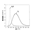
- FIG. 2 is a temperature programmed desorption profile of hydrogen molecules and water molecules of a glass sample into which hydrogen molecules are introduced.
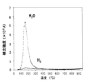
- FIG. 3 is a temperature programmed desorption profile of hydrogen molecules and water molecules of a glass sample into which hydrogen molecules are not introduced.
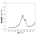
- FIG. 4 is a temperature programmed desorption profile of hydrogen molecules of silicon implanted with hydrogen ions.
- the TiO 2 —SiO 2 glass of the present invention will be described below.
- the hydrogen molecule concentration is 5 ⁇ 10 17 molecules / cm 3 or more.
- the hydrogen molecule concentration is 1 ⁇ 10 18 molecules / cm 3 or more, more preferably 5 ⁇ 10 18 molecules / cm 3 or more, and particularly preferably 1 ⁇ 10 19 molecules / cm 3 or more. In order to maintain the above effect for a longer period, it is preferably 5 ⁇ 10 19 molecules / cm 3 or more.
- the measurement of the hydrogen molecule concentration was carried out as follows using a thermal desorption spectrometer (TDS) manufactured by Electronic Science Co., Ltd. based on the specification of Japanese Patent No. 3298974.
- TDS thermal desorption spectrometer
- FIG. 2 shows the temperature programmed desorption profile of hydrogen molecules.
- the temperature desorption profile of water molecules is also shown in FIG.
- the peak observed near 200 to 800 ° C. with a maximum near 400 ° C. can be considered to be due to desorption of hydrogen molecules introduced into the glass. .
- the number of desorbed hydrogen molecules in the measurement sample can be calculated from the integral intensity ratio of the desorption peak of the hydrogen molecule between the measurement sample and a standard sample with a known hydrogen molecule concentration.
- the measurement method is as follows.
- 1 ⁇ 10 16 hydrogen ion-implanted silicon (manufactured by Denshi Kagaku Co., Ltd.) is placed in a temperature-programmed desorption analyzer and the inside of the measurement chamber is evacuated to 5 ⁇ 10 ⁇ 7 Pa or less and heated.
- the observed temperature-programmed desorption profile of hydrogen molecules is also shown in FIG.
- the hydrogen molecule in which a desorption peak was observed at around 350 to 750 ° C. with a maximum at around 550 ° C. was generated when 1 ⁇ 10 16 hydrogen ions in silicon were desorbed.
- the number of desorbed hydrogen molecules in FIG. 2 was calculated to be 1.3 ⁇ 10 17 . Further, from the measured volume (0.1 cm 3 ) of the glass sample, the hydrogen molecule concentration introduced into the glass sample is calculated as 1.3 ⁇ 10 18 molecules / cm 3 .
- the COT of TiO 2 —SiO 2 glass, the linear thermal expansion coefficient of 0 to 100 ° C. and ⁇ T can be obtained by using a known method, for example, a laser interferometric thermal dilatometer, for the linear thermal expansion coefficient (CTE) of TiO 2 —SiO 2 glass. It can be obtained by measuring in the range of ⁇ 150 to + 200 ° C. and plotting the relationship between CTE and temperature as shown in FIG.
- a laser interferometric thermal dilatometer for the linear thermal expansion coefficient (CTE) of TiO 2 —SiO 2 glass. It can be obtained by measuring in the range of ⁇ 150 to + 200 ° C. and plotting the relationship between CTE and temperature as shown in FIG.
- the COT of the optical system member placed in the exposure apparatus using high EUV energy light is in the range of 4 to 40 ° C. for the purpose of preventing the dimensional change due to the temperature change of the optical system member such as a mirror. It is desirable to be. Furthermore, it is desirable that the linear thermal expansion coefficient is ⁇ 5 to 5 ppb / ° C., that is, the range where the thermal expansion coefficient is almost zero is wide. Specifically, the temperature at which ⁇ 5 to 5 ppb / ° C. is preferably 4 ° C. or more. It has been suggested that the temperature of the optical system member rises locally because high energy EUV light is irradiated particularly on a member close to the light source. Although it depends on the irradiation conditions of EUV light, the temperature of the optical system member is estimated to rise to 40 to 110 ° C., and a temperature difference of about 4 to 6 ° C. may occur locally.
- the COT is in the range of 4 to 40 ° C.
- the COT of the TiO 2 —SiO 2 glass of the present invention is more preferably 11 to 33 ° C., particularly preferably 19 to 25 ° C.
- the linear thermal expansion coefficient of 0 to 100 ° C. is preferably in the range of ⁇ 130 to 130 ppb / ° C. Thereby, when high energy EUV light is irradiated, even if the temperature of an optical member changes from room temperature to high temperature, the change of a dimension or a shape can be made small.
- TiO 2 —SiO 2 glass of the present invention is more preferably in the range of ⁇ 110 to 110 ppb / ° C., further preferably in the range of ⁇ 90 to 90 ppb / ° C., particularly preferably ⁇ The range is 50 to 50 ppb / ° C.
- the inventors of the present application have found that the COT and the linear thermal expansion coefficient of 0 to 100 ° C. satisfy the above by controlling the TiO 2 concentration and the fictive temperature.
- the TiO 2 —SiO 2 glass of the present invention preferably has a TiO 2 content of 3 to 10% by mass.
- the COT tends to be in the range of 4 to 40 ° C.
- the TiO 2 content is 3% by mass or more, the COT tends to be 4 ° C. or more.
- the TiO 2 content is 10 wt% or more, COT tends to be 40 ° C. or less.
- crystals such as rutile are less likely to precipitate and bubbles are less likely to remain.
- the TiO 2 content is preferably 9% by mass or less, more preferably 8% by mass or less.
- the TiO 2 content is preferably 4% by mass or more, more preferably 5% by mass or more.
- the inventors of the present application are related to the fictive temperature and the range of the zero expansion temperature range, that is, related to the fictive temperature and ⁇ T. More specifically, it has been found that ⁇ T decreases as the fictive temperature increases, and ⁇ T increases as the fictive temperature decreases.
- the present inventors have found that the range of the linear thermal expansion coefficient of 0 to 100 ° C. is reduced by controlling the TiO 2 concentration and the fictive temperature.
- the TiO 2 —SiO 2 glass of the present invention has a linear thermal expansion coefficient of ⁇ 130 to 130 ppb / ° C. when the TiO 2 content is 3 to 10% by mass and the fictive temperature is 1100 ° C. or less. Prone to range.
- the linear thermal expansion coefficient of 0 to 100 ° C. may be less than ⁇ 130 ppb / ° C. or may exceed 130 ppb / ° C.
- TiO 2 —SiO 2 glass is used as an optical system for an EUVL exposure apparatus.
- thermal expansion due to a temperature change of the optical system member during EUV light irradiation may cause a problem.
- the fictive temperature is more preferably 1000 ° C. or lower, and further preferably 950 ° C. or lower.
- the fictive temperature is 900 ° C. or less.
- it is 850 ° C. or lower, and particularly preferably 800 ° C. or lower.
- ⁇ T is preferably 4 ° C. or higher.
- ⁇ T is more preferably 6 ° C. or higher, and further preferably 8 ° C. or higher.
- the CTE can be ⁇ 5 to 5 ppb / ° C. in the temperature range of 4 to 40 ° C., which is particularly preferable.
- the TiO 2 —SiO 2 glass of the present invention having a fictive temperature of 1100 ° C. or lower
- the TiO 2 —SiO 2 glass molded body formed into a predetermined shape was held at a temperature of 600 to 1200 ° C. for 2 hours or more. Thereafter, a method of lowering the temperature to 500 ° C. or less at an average temperature decrease rate of 10 ° C./hr or less is effective.
- the temperature is lowered at a slower average temperature reduction rate, a lower fictive temperature is achieved.
- the fictive temperature can be 900 ° C. or less.
- the temperature can be reduced by cooling at a cooling rate of 5 ° C./hr or more in other temperature ranges.
- the TiO 2 —SiO 2 glass molded body is held at a temperature of 600 to 1200 ° C. for 2 hours or more and then an average temperature decreasing rate of 10 ° C./hr or less. What is necessary is just to cool down to 500 degrees C or less.
- the fictive temperature of TiO 2 —SiO 2 glass can be measured by a known procedure. In examples described later, the fictive temperature of TiO 2 —SiO 2 glass is measured by the following procedure.
- an absorption spectrum is obtained using an infrared spectrometer (in the examples described below, Magna 760 manufactured by Nikolet is used).
- the data interval is set to about 0.5 cm ⁇ 1 , and the average value obtained by scanning 64 times is used as the absorption spectrum.
- the peak observed in the vicinity of about 2260 cm ⁇ 1 is due to the overtone of stretching vibration due to the Si—O—Si bond of the TiO 2 —SiO 2 glass.
- a calibration curve is created with glass having the same fictive temperature and the same composition, and the fictive temperature is obtained.
- the reflection spectrum of the surface is similarly measured using a similar infrared spectrometer.
- the peak observed in the vicinity of about 1120 cm ⁇ 1 is due to stretching vibration due to the Si—O—Si bond of the TiO 2 —SiO 2 glass.
- a calibration curve is created with glass having the same fictive temperature and the same composition, and the fictive temperature is obtained. Note that the shift of the peak position due to the change in the glass composition can be extrapolated from the composition dependency of the calibration curve.
- the TiO 2 —SiO 2 glass of the present invention preferably has a fictive temperature variation of 50 ° C. or less, more preferably 30 ° C. or less. If the variation in the fictive temperature exceeds the above range, there may be a difference in the coefficient of thermal expansion depending on the location.
- variable of virtual temperature is defined as the difference between the maximum value and the minimum value of virtual temperature within 30 mm ⁇ 30 mm in at least one plane.
- the variation in fictive temperature can be measured as follows.
- a transparent TiO 2 —SiO 2 glass body molded into a predetermined size is sliced into a 50 mm ⁇ 50 mm ⁇ 6.35 mm TiO 2 —SiO 2 glass block.
- the fictive temperature variation of the formed TiO 2 —SiO 2 glass body is obtained by measuring the fictive temperature in accordance with the method described above at intervals of 10 mm on the 50 mm ⁇ 50 mm surface of the TiO 2 —SiO 2 glass block.
- the TiO 2 —SiO 2 glass of the present invention preferably has an OH concentration of 600 mass ppm or more in order to set the fictive temperature to 1100 ° C. or less.
- the inclusion of OH is an effective means for lowering the fictive temperature of TiO 2 —SiO 2 glass.
- the OH concentration is less than 600 ppm by mass, it takes a very long time to obtain a TiO 2 —SiO 2 glass having a fictive temperature of 1100 ° C. or lower.
- the OH concentration of the TiO 2 —SiO 2 glass can be measured using a known method. For example, it is possible to obtain an OH concentration from an absorption peak at a wavelength of 2.7 ⁇ m by measuring with an infrared spectrophotometer (JP Williams et. Al., American Ceramic Science Bulletin, 55 (5), 524). 1976). The detection limit by this method is 0.1 mass ppm.
- porous TiO 2 —SiO 2 glass is obtained by depositing and growing TiO 2 —SiO 2 glass fine particles (soot) obtained by flame hydrolysis or thermal decomposition of a silica precursor and a titania precursor as glass forming raw materials. Get the body.
- the obtained porous TiO 2 —SiO 2 glass body is heated to a densification temperature or higher, and further heated to a transparent vitrification temperature or higher to obtain a transparent TiO 2 —SiO 2 glass body.
- a direct method is mentioned as another method.
- a silica precursor and titania precursor as glass forming raw materials are hydrolyzed and oxidized in an oxyhydrogen flame at 1800 to 2000 ° C. to obtain a TiO 2 —SiO 2 glass body containing hydrogen. It is. At this time, the hydrogen molecule concentration is adjusted by adjusting the flame temperature and gas concentration.
- the densification temperature refers to a temperature at which the porous glass body can be densified until no voids can be confirmed with an optical microscope.
- the transparent vitrification temperature refers to a temperature at which crystals cannot be confirmed with an optical microscope and transparent glass is obtained.
- the linear thermal expansion coefficient distribution is within 30 mm ⁇ 30 mm in at least one plane. It can be achieved within 30 ppb / ° C., and is suitable as an optical system member for an EUVL exposure apparatus.
- the linear thermal expansion coefficient distribution of TiO 2 —SiO 2 glass can be measured using a known method. For example, a transparent TiO 2 —SiO 2 glass body molded into a predetermined size is cut and divided into 15 mm ⁇ 15 mm ⁇ 1 mm TiO 2 —SiO 2 glass pieces, and each piece is lined according to the method described above. By measuring the thermal expansion coefficient, the variation in the linear thermal expansion coefficient of the formed TiO 2 —SiO 2 glass block is obtained.
- the glass forming raw material is not particularly limited as long as it is a gasifiable raw material.
- silica precursor examples include chlorides such as SiCl 4 , SiHCl 3 , SiH 2 Cl 2 , and SiH 3 Cl, SiF 4 , SiHF 3 , fluorides such as SiH 2 F 2, SiBr 4, SiHBr bromides such as 3, halogenated silicon compounds such as iodide such as SiI 4, R n Si (OR) 4- n ( wherein R is 1 to 4 carbon atoms Wherein n is an integer of 0 to 3. A plurality of Rs may be the same or different from each other), and titania precursors include halogens such as TiCl 4 and TiBr 4.
- titanium compound R n Ti (OR) 4- n (wherein R is an alkyl group having 1 to 4 carbon atoms, n represents 0 integer. multiple R of 1-3 may be the same or different from each other. In include alkoxy titanium represented. In addition, Si and Ti compounds such as silicon titanium double alkoxide can be used as the silica precursor and titania precursor.
- a seed rod made of quartz glass for example, a seed rod described in Japanese Patent Publication No. 63-24973
- the porous TiO 2 —SiO 2 glass body obtained in the step (a) is heated to a densification temperature under reduced pressure or in a helium atmosphere to obtain a TiO 2 —SiO 2 dense body.
- the densification temperature is usually 1250 to 1550 ° C., and particularly preferably 1300 to 1500 ° C.
- the temperature at which OH doping is performed is preferably a high temperature equal to or lower than the densification temperature, and is preferably 800 to 1200 ° C.
- Step (C) The TiO 2 —SiO 2 dense body obtained in step (b) is heated to the transparent vitrification temperature to obtain a transparent TiO 2 —SiO 2 glass body.
- the transparent vitrification temperature is usually from 1350 to 1800 ° C., particularly preferably from 1400 to 1750 ° C.
- the atmosphere is preferably an atmosphere of 100% inert gas such as helium or argon, or an atmosphere mainly composed of an inert gas such as helium or argon.
- the pressure may be reduced pressure or normal pressure. In the case of reduced pressure, 13000 Pa or less is preferable.
- Step (D) The transparent TiO 2 —SiO 2 glass body obtained in the step (c) is heated to a temperature equal to or higher than the softening point and formed into a desired shape to obtain a molded TiO 2 —SiO 2 glass body.
- the molding temperature is preferably 1500 to 1800 ° C.
- the viscosity is sufficiently lowered to such an extent that the transparent TiO 2 —SiO 2 glass is substantially self-weight deformed. Further, the growth of cristobalite, which is a crystal phase of SiO 2 , or the growth of rutile or anatase, which is a crystal phase of TiO 2 , hardly occurs, and so-called devitrification can be prevented. Below 1800 ° C., sublimation of SiO 2 can be suppressed.
- step (E) After holding the shaped TiO 2 —SiO 2 glass body obtained in step (d) at a temperature of 600 to 1200 ° C. for 1 hour or more, 500 ° C. or less at an average temperature reduction rate of 10 ° C./hr or less.
- An annealing process for lowering the temperature is performed to control the fictive temperature of the TiO 2 —SiO 2 glass.
- the formed TiO 2 —SiO 2 glass body obtained in the step (d) at 1200 ° C. or more is subjected to an annealing treatment for lowering the temperature to 500 ° C. at an average temperature reduction rate of 60 ° C./hr or less, and the TiO 2 —SiO 2 glass Control the virtual temperature.
- the pressure is preferably reduced pressure or normal pressure.
- the slowest cooling rate is preferably 10 ° C./hr or less, more preferably 5 ° C./hr or less, further preferably 3 ° C./hr or less, particularly preferably. Is 1 ° C./hr or less.
- Step TiO 2 —SiO 2 glass body obtained in the step (e) is held in a hydrogen atmosphere at a temperature of 300 to 1200 ° C. for 10 hours or longer to contain TiO 2 —SiO 2 containing hydrogen.
- a glass body is obtained.
- the atmosphere is preferably a 100% hydrogen atmosphere or a hydrogen atmosphere containing an inert atmosphere such as helium or argon.
- the hydrogen partial pressure is preferably 0.1 atm or higher, more preferably 1 atm or higher. Preferably it is 5 atmospheres or more.
- the holding time is preferably 10 hours or more, more preferably 24 hours or more.
- the TiO 2 —SiO 2 glass of the present invention preferably has no inclusion.
- the inclusion is a foreign substance or bubble present in the glass. Foreign matter may be generated by contamination or crystal precipitation in the glass production process. In order to eliminate inclusions such as foreign matters and bubbles, it is necessary to suppress contamination in the above manufacturing process, particularly in step (a), and to accurately control the temperature conditions in steps (b) to (d). is necessary.
- the TiO 2 —SiO 2 glass of the present invention When producing the TiO 2 —SiO 2 glass of the present invention by a direct method, (1) increasing the hydrogen molecule concentration during synthesis, (2) increasing the flame temperature, and (3) compared with the usual synthesis conditions. It is necessary to devise such as raising the deposition surface temperature and (4) lowering the raw material gas concentration.
- the combustion gas one containing H in the molecular formula is used, but the O / H ratio in all the supplied gases is preferably 1.5 or less, and more preferably 1.3 or less.
- the flame temperature is preferably 1900 ° C. or higher, more preferably 2000 ° C. or higher.
- the deposition surface temperature is preferably 1800 ° C. or higher, and is 1900 ° C. or higher.
- the raw material gas concentration in the pipe for conveying the raw material gas to the burner is preferably 20% by volume or less, and more preferably 10% by volume or less. Of the above four items, two or more items are more preferable, three or more items are more preferable, and all of these are particularly preferable.
- the TiO 2 —SiO 2 glass of the present invention can suppress the change over time of the reflective multilayer film composed of a metal such as Mo or Si by releasing hydrogen molecules, and can maintain the physical properties of the multilayer film. . Since hydrogen molecules in the glass are released by diffusion, it is preferable that the hydrogen molecule concentration in the glass is high. Since hydrogen gas diffuses through the gaps in the glass structure, the glass preferably has a structure with a large gap. Silica glass has a structure with a large gap in glass, but a structure with a larger gap can be obtained by further doping TiO 2 into silica glass. In addition, the TiO 2 —SiO 2 glass can have a structure with a larger gap as the fictive temperature is lower. Further, the TiO 2 —SiO 2 glass can have a structure with a larger gap when the OH concentration is lower.
- silica glass containing TiO 2 having a fictive temperature of 1100 ° C. or lower and a hydrogen molecule concentration of 5 ⁇ 10 17 molecules / cm 3 or higher is an EUV lithography optical material that is irradiated with EUV light for a long time. It can be used as a member.
- the TiO 2 —SiO 2 glass of the present invention can be used for an optical member for EUV lithography that is irradiated with EUV light for 10,000 hours or more in total. Further, if the TiO 2 content is 3 to 10% by mass or the fictive temperature is 1000 ° C. or less, the diffusion coefficient of hydrogen increases.
- the OH concentration is preferably less than 600 ppm by mass and more preferably less than 200 ppm by mass for use in an EUV lithography optical member that is irradiated with EUV light for a longer time. More preferably, it is less than 100 ppm by mass, and particularly preferably less than 60 ppm by mass.
- Example 1 to 4 and Example 7 are examples, and the others are comparative examples.
- Example 1 TiCl 4 and SiCl 4 as glass-forming raw material for TiO 2 -SiO 2 glass, was mixed after each is gasified, TiO 2 -SiO to subjecting the mixture to heat hydrolysis in an oxyhydrogen flame (flame hydrolysis) 2 Deposit and grow glass fine particles on a rotating seed rod to form a porous TiO 2 —SiO 2 glass body (step (a)).
- oxyhydrogen flame flame hydrolysis
- the obtained porous TiO 2 —SiO 2 glass body is difficult to handle as it is, it is kept in the atmosphere at 1200 ° C. for 6 hours, and then removed from the seed rod.
- step (b) a TiO 2 —SiO 2 dense body is obtained (step (b)).
- the obtained TiO 2 —SiO 2 dense body is heated to 1700 ° C. in an argon atmosphere using a carbon furnace to obtain a transparent TiO 2 —SiO 2 glass body (step (c)).
- the obtained transparent TiO 2 —SiO 2 glass body is heated to 1750 ° C. and formed into a desired shape to obtain a formed TiO 2 —SiO 2 glass body (step (d)).
- the obtained glass is held at 1100 ° C. for 10 hours, cooled to 500 ° C. at a rate of 10 ° C./hr, and allowed to cool to the atmosphere (step (e)).
- the obtained glass is held at 500 ° C. for 73 hours in an atmosphere of 100% hydrogen and 10 atm to obtain a TiO 2 —SiO 2 glass body containing hydrogen (step (f)).
- Example 2 In the step (e) of Example 1, the obtained glass was held at 1100 ° C. for 10 hours, lowered to 900 ° C. at a rate of 10 ° C./hr, then lowered to 700 ° C. at a rate of 1 ° C./hr, Example 1 except that the temperature is lowered to 500 ° C. at a rate of 10 ° C./hr and allowed to cool to the atmosphere, and in the step (f), hydrogen is maintained at 500 ° C. for 146 hours in an atmosphere of 10% atmospheric pressure. Similarly, a TiO 2 —SiO 2 glass body is obtained.
- Example 3 In the step (a) of Example 1, the supply amount of TiCl 4 is increased, and in the step (e), the obtained glass is held at 1100 ° C. for 10 hours, and is increased to 900 ° C. at a rate of 10 ° C./hr.
- Example 4 In the same manner as in Example 1, except that the supply amount of TiCl 4 is increased in the step (a) of Example 1, and the hydrogen is maintained at 500 ° C. for 146 hours in an atmosphere of 100% hydrogen at the step (f). Thus, a TiO 2 —SiO 2 glass body is obtained.
- Example 5 In the step (a) of Example 1, a TiO 2 —SiO 2 glass body is obtained in the same manner as in Example 1 except that the supply amount of TiCl 4 is slightly increased and the step (f) is not performed.
- Example 6 Corning ULE # 7972, known as zero expansion TiO 2 —SiO 2 glass.
- Example 7 TiCl 4 and SiCl 4 as glass-forming raw material for TiO 2 -SiO 2 glass, was mixed after each is gasified, TiO 2 -SiO to subjecting the mixture to heat hydrolysis in an oxyhydrogen flame (flame hydrolysis) 2 Deposit and grow glass fine particles on a rotating seed rod to form a porous TiO 2 —SiO 2 glass body (step (a)).
- oxyhydrogen flame flame hydrolysis
- the obtained porous TiO 2 —SiO 2 glass body is difficult to handle as it is, it is kept in the atmosphere at 1200 ° C. for 6 hours, and then removed from the seed rod.
- the porous TiO 2 —SiO 2 glass body was placed in an electric furnace capable of controlling the atmosphere, and after reducing the pressure to 1330 Pa at room temperature, water was put in a glass bubbler and helium gas was added at atmospheric pressure and 100 ° C. with He gas. While bubbling is performed and water vapor is introduced into the furnace together with He gas, this atmosphere is maintained at 1000 ° C. under normal pressure for 4 hours to perform OH doping.
- step (b) Thereafter, the temperature is raised to 1450 ° C. in the same atmosphere, and then kept at this temperature for 4 hours to obtain a TiO 2 —SiO 2 dense body (step (b)).
- the obtained TiO 2 —SiO 2 dense body is heated to 1700 ° C. in an argon atmosphere using a carbon furnace to obtain a transparent TiO 2 —SiO 2 glass body (step (c)).
- the obtained transparent TiO 2 —SiO 2 glass body is heated to 1750 ° C. and formed into a desired shape to obtain a formed TiO 2 —SiO 2 glass body (step (d)).
- the obtained glass is held at 1100 ° C. for 10 hours, and the temperature is lowered to 900 ° C. at a rate of 10 ° C./hr. The temperature is lowered and allowed to cool to the atmosphere (step (e)).
- the obtained glass is held at 500 ° C. for 146 hours in an atmosphere of 100% hydrogen at 10 atm to obtain a TiO 2 —SiO 2 glass body containing hydrogen (step (f)).
- the measurement results of the physical properties of the glasses of Examples 1 to 7 are summarized in Table 1. In addition, about evaluation, it performs according to the above-mentioned measuring method, respectively. Further, the COT in Table 1 is derived by obtaining the temperature at which the linear thermal expansion coefficient is 0 ppb / ° C. from the curve of FIG. ⁇ T in Table 1 is derived from the temperature range in which the linear thermal expansion coefficient is ⁇ 5 to 5 ppb / ° C. from the curve of FIG.
- the glass of Examples 1 to 4 and Example 7 has a high hydrogen molecule concentration of 5 ⁇ 10 17 molecules / cm 3 or more and a fictive temperature of 1100 ° C. or less, a multilayer film can be obtained by releasing hydrogen from the glass. This is suitable for an optical system member of an EUVL exposure apparatus.
- the silica glass and optical member of the present invention are suitable for an exposure apparatus for EUV lithography.
Landscapes
- Chemical & Material Sciences (AREA)
- Engineering & Computer Science (AREA)
- Physics & Mathematics (AREA)
- Nanotechnology (AREA)
- Chemical Kinetics & Catalysis (AREA)
- General Physics & Mathematics (AREA)
- Materials Engineering (AREA)
- Organic Chemistry (AREA)
- Geochemistry & Mineralogy (AREA)
- Crystallography & Structural Chemistry (AREA)
- Life Sciences & Earth Sciences (AREA)
- Manufacturing & Machinery (AREA)
- General Chemical & Material Sciences (AREA)
- Mathematical Physics (AREA)
- Theoretical Computer Science (AREA)
- Thermal Sciences (AREA)
- Condensed Matter Physics & Semiconductors (AREA)
- Glass Compositions (AREA)
- Preparing Plates And Mask In Photomechanical Process (AREA)
- Exposure And Positioning Against Photoresist Photosensitive Materials (AREA)
- Exposure Of Semiconductors, Excluding Electron Or Ion Beam Exposure (AREA)
Abstract
EUVL用露光装置の光学系部材として使用した場合に、室温における熱膨張係数がほぼゼロとなり、ガラスから水素を放出させることで多層膜の物性を長時間維持させることが可能なTiO2-SiO2ガラスを提供する。本発明は、仮想温度が1100℃以下であり、水素分子濃度が5×10¹⁷分子/cm3以上であり、線熱膨張係数が0ppb/℃となる温度が4~40℃の範囲にあることを特徴とするTiO2を含有するシリカガラスに関する。
Description
本発明は、TiO2を含有するシリカガラス(以下、本明細書では、TiO2-SiO2ガラスと記す)に関し、特にEUVリソグラフィ用の露光装置の光学系部材として用いられるTiO2-SiO2ガラスに関する。なお、本発明でいうEUV(Extreme Ultra Violet)光とは、軟X線領域または真空紫外域の波長帯の光を指し、具体的には波長が0.2~100nm程度の光のことである。
従来から、光リソグラフィ技術においては、ウェハ上に微細な回路パターンを転写して集積回路を製造するための露光装置が広く利用されている。集積回路の高集積化および高機能化に伴い、集積回路の微細化が進み、露光装置には深い焦点深度で高解像度の回路パターンをウェハ面上に結像させることが求められ、露光光源の短波長化が進められている。
露光光源としてEUV光(極端紫外光)のうち代表的には波長13nmの光を用いたリソグラフィ技術が、回路パターンの線幅が32nm以降の世代にわたって適用可能と見られ注目されている。EUVリソグラフィ(以下、「EUVL」と略する)の像形成原理は、投影光学系を用いてマスクパターンを転写する点では、従来のフォトリソグラフィーと同じである。しかし、EUV光のエネルギー領域では光を透過する材料が無いために、屈折光学系は用いることができず、光学系はすべて反射光学系となる。
EUVL用露光装置の光学系部材はフォトマスクやミラーなどであるが、(1)基材、(2)基材上に形成された反射多層膜、(3)反射多層膜上に形成された吸収体層、から基本的に構成される。反射多層膜としては、Mo層と、Si層とを交互に積層させたMo/Si反射多層膜を形成することが検討され、吸収体層には、成膜材料として、TaやCrが検討されている。基材としては、EUV光照射の下においても歪みが生じないよう低熱膨張係数を有する材料が必要とされ、低熱膨張係数を有するガラス等が検討されている。
TiO2-SiO2ガラスは、石英ガラスよりも小さい熱膨張係数(Coefficient of Thermal Expansion;CTE)を有する超低熱膨張材料として知られ、またガラス中のTiO2含有量によって熱膨張係数を制御できるために、熱膨張係数が0に近いゼロ膨張ガラスが得られる。したがって、TiO2-SiO2ガラスはEUVL用露光装置の光学系部材に用いる材料としての可能性がある。
従来のTiO2-SiO2ガラスの作製方法は、まず、シリカ前駆体とチタニア前駆体をそれぞれ蒸気形態に転化させてこれらを混合する。この蒸気形態となった混合物は、バーナーに導入され熱分解することでTiO2-SiO2ガラス粒子となる。このTiO2-SiO2ガラス粒子は耐火性容器中に堆積され、堆積と同時にそこで溶融されてTiO2-SiO2ガラスとなる。
特許文献1には、TiO2-SiO2多孔質ガラス体を形成し、ガラス体にした後、マスク基板を得る方法が開示されている。
EUVL用露光装置内に組み込まれるミラーは、30000時間といった長時間のEUV照射に耐えなければならず、多層膜の特性の経時変化が問題となる。主な経時変化の原因は、カーボンのコンタミネーションと極微量の水分による多層膜の酸化によるものである。カーボンのコンタミネーションをクリーニングしたり、酸化した多層膜を還元したりするために、水素を用いる技術が報告されている(例えば、非特許文献1、2参照。)。
S.Graham, C.Steinhaus, M.Clift,L.Klebanoff, and S.Bajt, Proceedings of SPIE Vol.5037 pp.460-469(2003)
H.Oizumi, A.Izumi, K.Motai, I Nishiyama, and A.Namiki, Japanese Journal of Applied Physics Vol.46 No.25 pp.L633-L635(2007)
EUVL用露光装置光学部材はEUV光が照射されるため、光学部材中で局所的に温度上昇が生じることが示唆されている。光学部材の温度上昇による熱膨張により、フォトマスクなどの場合はパターンのピッチが変化するなどの問題が生じる。そのため、EUVL用露光装置光学部材はEUV光が照射される室温付近の熱膨張係数がほぼゼロであり、熱膨張係数がゼロとなる温度範囲が広いことが好ましい。
また、EUVL用露光装置光学部材はEUV照射により多層膜の経時変化が生じることが知られている。多層膜が劣化した光学部材は新たな光学部材に交換する必要がある他、光学系の調製などに多大な時間とコストを有することから、EUV照射による多層膜の経時変化が少ないEUVL用露光装置光学部材が求められている。
上記した非特許文献では、カーボンのコンタミネーションをクリーニングしたり、酸化した多層膜を還元したりすることにより、多層膜の長寿命化に関する技術が開示されているが、水素雰囲気を用いる必要があり、簡便ではない点で問題である。
EUVエネルギー光による熱を用いることで、雰囲気中に水素が存在すれば、前述のカーボンコンタミネーションのクリーニング効果や、酸化した多層膜の還元効果が期待できる。また、雰囲気中に水素が存在することで、多層膜の酸化そのものも抑制することが期待できる。ガラス中に水素分子が含まれている場合、水素分子は拡散係数が他の成分に比べて極端に大きいことから、水素はガラス内部から放出される。特に、ガラスの温度が高ければ高いほど、水素分子の放出は起こりやすくなることが考えられる。
しかしながら、上記した特許文献1に記載のガラス体は、熱膨張係数がほぼゼロとなる温度範囲が広いが、ガラス中の水素分子濃度が5×10¹⁷分子/cm3未満であるため、EUVエネルギー光による熱を用いた、カーボンコンタミネーションのクリーニング効果や、酸化した多層膜の還元効果が十分に期待できない問題がある。また上記した特許文献1に記載のガラス体で、カーボンコンタミネーションのクリーニング効果を得るには、更に強い高EUVエネルギー光を照射する必要が有り、この高EUV光の照射による多層膜の劣化が無視できない可能性がある。
上記した従来技術の問題点を解決するため、本発明は、露光装置用の光学系部材として好適な熱膨張特性を有し、かつガラスから水素を放出させることで多層膜の物性を長時間維持させることが可能となるTiO2-SiO2ガラスを提供することを目的とする。
仮想温度が1100℃以下であり、水素分子濃度が5×10¹⁷分子/cm3以上であり、線熱膨張係数(CTE)が0ppb/℃となる温度(クロスオーバー温度:Cross-over Temperature;COT)が4~40℃の範囲にあることを特徴とするTiO2を含有するシリカガラス(以下、「本発明のTiO2-SiO2ガラス」という。)を提供する。
本発明のTiO2-SiO2ガラスにおいては、TiO2含有量が3~10質量%であることが好ましい。
また、0~100℃の線熱膨張係数が-130~130ppb/℃の範囲にあることが好ましい。
さらに、線熱膨張係数(CTE)が-5~5ppb/℃となる温度幅(ΔT)が4℃以上であることが好ましい。
さらに、本発明のTiO2-SiO2ガラスにおいては、インクルージョンがないことが好ましい。
また、本発明のTiO2-SiO2ガラスは、EUVリソグラフィ用光学部材に用いることができる。
また、本発明のTiO2-SiO2ガラスは、積算で10000時間以上のEUV光が照射されるEUVリソグラフィ用光学部材に用いることができる。
本発明のTiO2-SiO2ガラスは、EUVエネルギー光が照射される室温付近での線熱膨張係数がほぼゼロとなるため、EUVL用露光装置の光学系部材としてきわめて好適である。また、ガラスから水素を放出させることで多層膜の物性を長時間維持させることが可能となる。
以下、本発明のTiO2-SiO2ガラスを説明する。
本発明のTiO2-SiO2ガラスにおいて、水素分子濃度が5×10¹⁷分子/cm3以上である。水素分子濃度が5×1017分子/cm3未満の場合、カーボンコンタミネーションのクリーニング効果や、酸化した多層膜の還元効果が期待できない。より好ましくは水素分子濃度は1×1018分子/cm3以上、さらに好ましくは5×1018分子/cm3以上、特に好ましくは1×1019分子/cm3以上である。より長期にわたって上記の効果を持続させるには、5×1019分子/cm3以上であることが好ましい。
水素分子濃度の測定は、日本国特許第3298974号明細書に基づく電子科学株式会社製の昇温脱離分析装置(Thermal Desorption Spectrometer;TDS)を用いて以下のように行った。
水素分子を導入したガラス試料を昇温脱離分析装置内に入れ、その測定室内部を5×10⁻⁷Pa以下まで真空引きした後ガラス試料を加熱し、発生したガスの質量数を分析装置内部に設置された質量分析計にて測定した。水素分子の昇温脱離プロファイルを図2に示す。なお参考に水分子の昇温脱離プロファイルも合わせて図2に示す。
水素分子の脱離プロファイルにおいて、400℃付近を最大とし200~800℃付近にピークが観測された。また水分子の脱離プロファイルにおいて150℃付近を最大とし100~200℃付近に観測されたピークは、ガラス表面に物理吸着した水が脱離したものによると考えられる。
次に水素分子を導入していないガラス試料を、同様に、昇温脱離分析装置内に入れ測定室内部を5×10⁻⁷Pa以下まで真空引きした後加熱し、発生したガスの質量数を測定した。観測された水素分子および水分子の昇温脱離プロファイルを同様に図3に示す。水分子の脱離プロファイルでは、図2と同様に、100~200℃付近に物理吸着水の脱離によると考えられるピークが観測された。これに対し水素分子の脱離プロファイルでは、図2に観測された400℃付近を最大としたピークは観測されなかった。
これより図2における水素分子の脱離プロファイルにおいて、400℃付近を最大とし200~800℃付近に観測されたピークは、ガラス中に導入した水素分子が脱離したことによるものと考えることができる。
したがって、測定サンプルと水素分子濃度が既知の標準サンプルとの上記水素分子の脱離ピークの積分強度比より、測定サンプルの脱離した水素分子数を算出することができる。
例えば、標準サンプルとして水素イオン注入したシリコンを用いた場合、以下のような測定方法となる。
1×10¹⁶個の水素イオン注入したシリコン(電子科学株式会社製)を、同様に、昇温脱離分析装置内に入れ測定室内部を5×10⁻⁷Pa以下まで真空引きした後加熱し、観測された水素分子の昇温脱離プロファイルを同様に図4に示す。550℃付近を最大とし350~750℃付近に脱離ピークが観測された水素分子は、シリコン中の1×10¹⁶個の水素イオンが脱離した際に発生したものである。
図2および図4における水素分子の脱離ピークの積分強度比より、図2にて脱離した水素分子数を1.3×10¹⁷個と算出した。さらに測定したガラス試料の体積(0.1cm3)より、ガラス試料に導入した水素分子濃度を1.3×10¹⁸分子/cm3と算出する。
TiO2-SiO2ガラスのCOT、0~100℃の線熱膨張係数およびΔTは、TiO2-SiO2ガラスの線熱膨張係数(CTE)を公知の方法、例えば、レーザー干渉式熱膨張計を用いて-150~+200℃の範囲で測定し、CTEと温度の関係を図1に示すようにプロットすることにより求めることができる。
EUVLを実施する際、ミラー等の光学系部材の温度変化による寸法形状変化を防ぐ目的から、高EUVエネルギー光を用いた露光装置内に置かれる光学系部材のCOTは4~40℃の範囲にあることが望ましい。さらに線熱膨張係数が-5~5ppb/℃、すなわち熱膨張係数がほぼゼロとなる範囲が広いことが望ましい。具体的には-5~5ppb/℃となる温度が4℃以上であることが好ましい。光学系部材の温度は、特に光源に近い部材においては、高エネルギーのEUV光が照射されるため、局所的に上昇することが示唆されている。EUV光の照射条件にもよるが、光学系部材の温度は40~110℃に上がることが推測されており、さらに局所的に4~6℃程度の温度差が生じる場合がある。
本発明のTiO2-SiO2ガラスにおいて、COTは4~40℃の範囲にある。本発明のTiO2-SiO2ガラスのCOTは、より好ましくは11~33℃、特に好ましくは19~25℃である。
本発明のTiO2-SiO2ガラスにおいて、0~100℃の線熱膨張係数は-130~130ppb/℃の範囲であることが好ましい。これにより、高エネルギーのEUV光が照射された際に、光学部材の温度が室温から高温になっても寸法や形状の変化を小さくすることができる。本発明のTiO2-SiO2ガラスの、0~100℃の線熱膨張係数は、より好ましくは-110~110ppb/℃の範囲、さらに好ましくは-90~90ppb/℃の範囲、特に好ましくは-50~50ppb/℃の範囲である。
本願発明者らは、TiO2濃度、仮想温度を制御することによりCOTおよび0~100℃の線熱膨張係数が上記を満たすことを見出した。
TiO2-SiO2ガラスは、含有するTiO2濃度により、熱膨張係数が変化することが知られている(例えば、P.C.Schultz and H.T.Smyth, in: R.W.Douglas and B.Ellis, Amorphous Materials, Willey, New York, p.453(1972)参照)。
したがって、TiO2-SiO2ガラスのTiO2含有量を調節することによって、該TiO2-SiO2ガラスのCOTを調節することができる。
本発明のTiO2-SiO2ガラスは、TiO2含有量が3~10質量%であることが好ましい。TiO2含有量が当該範囲であると、COTが4~40℃の範囲になりやすい。具体的には、TiO2含有量が3質量%以上であると、COTが4℃以上となりやすい。また、TiO2含有量が10質量%以上であると、COTが40℃以下となりやすい。また、ルチルなどの結晶が析出しにくくり、泡が残りにくくなる。TiO2含有量は、好ましくは9質量%以下、より好ましくは8質量%以下である。また、TiO2含有量は、好ましくは4質量%以上、より好ましくは5質量%以上である。
日本国特開2005-104820号公報で述べているように、本願発明者らは、仮想温度とゼロ膨張の温度範囲の広さに関連があること、すなわち、仮想温度とΔTに関連があること、より具体的には、仮想温度が高くなるとΔTが狭くなり、仮想温度が低くなるとΔTが広くなることを見出している。
さらに本願発明者らはTiO2濃度、仮想温度を制御することにより0~100℃の線熱膨張係数の範囲が小さくなることを見出した。
本発明のTiO2-SiO2ガラスは、TiO2含有量が3~10質量%でかつ仮想温度が1100℃以下であると、0~100℃の線熱膨張係数が-130~130ppb/℃の範囲となりやすい。仮想温度が1100℃超だと、0~100℃の線熱膨張係数が-130ppb/℃未満、あるいは130ppb/℃超となる場合があり、TiO2-SiO2ガラスをEUVL用露光装置の光学系部材として使用した場合に、EUV光照射時に光学系部材の温度変化による熱膨張が問題となるおそれがある。仮想温度はより好ましくは1000℃以下、さらに好ましくは950℃以下である。0~100℃の線熱膨張係数の範囲をより小さく、具体的には0~100℃の線熱膨張係数が-50~50ppb/℃の範囲とするためには、仮想温度は900℃以下であることが好ましく、850℃以下であることがさらに好ましく、800℃以下であることが特に好ましい。
また、本発明のTiO2-SiO2ガラスにおいて、ΔTが4℃以上であることが好ましい。ΔTが4℃以上であると、TiO2-SiO2ガラスをEUVL用露光装置の光学系部材として使用した場合に、EUV光照射時の光学系部材の熱膨張の問題がより起こりにくい。ΔTは、より好ましくは6℃以上、さらに好ましくは8℃以上である。ΔTが15℃以上になると4~40℃の温度範囲でCTEが-5~5ppb/℃を達成することができるので、特に好ましい。
仮想温度が1100℃以下の本発明のTiO2-SiO2ガラスを得るためには、所定の形状に成形したTiO2-SiO2ガラス成形体を600~1200℃の温度にて2時間以上保持した後、10℃/hr以下の平均降温速度で500℃以下まで降温する方法が効果的である。より仮想温度を下げるためには、5℃/hr以下の速度で降温することが好ましく、3℃/hr以下の速度で降温することがより好ましい。より遅い平均降温速度で降温すれば、より低い仮想温度が達成される。例えば、1℃/hr以下の速度で降温すれば、仮想温度は900℃以下に成り得るが、その場合は1000~800℃の温度範囲のみを遅い冷却速度、例えば、1℃/hr以下の速度で降温し、それ以外の温度域は5℃/hr以上の冷却速度で冷却することで時間を短縮することができる。
同様に、仮想温度のばらつきを50℃以内とするには、TiO2-SiO2ガラス成形体を600~1200℃の温度にて2時間以上保持した後、10℃/hr以下の平均降温速度で500℃以下まで降温すればよい。
TiO2-SiO2ガラスの仮想温度は公知の手順で測定することができる。後述する実施例では、以下の手順でTiO2-SiO2ガラスの仮想温度を測定する。
鏡面研磨されたTiO2-SiO2ガラスについて、吸収スペクトルを赤外分光計(後述する実施例では、Nikolet社製Magna760を使用)を用いて取得する。この際、データ間隔は約0.5cm-1にし、吸収スペクトルは、64回スキャンさせた平均値を用いる。このようにして得られた赤外吸収スペクトルにおいて、約2260cm-1付近に観察されるピークがTiO2-SiO2ガラスのSi-O-Si結合による伸縮振動の倍音に起因する。このピーク位置を用いて、仮想温度が既知で同組成のガラスにより検量線を作成し、仮想温度を求める。あるいは、表面の反射スペクトルを同様の赤外分光計を用いて、同様に測定する。このようにして得られた赤外反射スペクトルにおいて、約1120cm-1付近に観察されるピークがTiO2-SiO2ガラスのSi-O-Si結合による伸縮振動に起因する。このピーク位置を用いて、仮想温度が既知で同組成のガラスにより検量線を作成し、仮想温度を求める。なお、ガラス組成の変化によるピーク位置のシフトは、検量線の組成依存性から外挿することが可能である。
本発明のTiO2-SiO2ガラスは、仮想温度のばらつきが50℃以内であることが好ましく、より好ましくは30℃以内である。仮想温度のばらつきが上記範囲を超えると、場所により、熱膨張係数に差を生じるおそれがある。
本明細書では、「仮想温度のばらつき」を少なくとも1つの面内における30mm×30mm内での仮想温度の最大値と最小値の差と定義する。
仮想温度のばらつきは以下のように測定できる。所定のサイズに成形した透明TiO2-SiO2ガラス体をスライスし、50mm×50mm×6.35mmのTiO2-SiO2ガラスブロックとする。このTiO2-SiO2ガラスブロックの50mm×50mm面について、10mmピッチの間隔で前述の方法に従い仮想温度の測定を行うことで、成形TiO2-SiO2ガラス体の仮想温度のばらつきを求める。
本発明のTiO2-SiO2ガラスは、仮想温度を1100℃以下とするため、OH濃度が600質量ppm以上であることが好ましい。
OHの添加により、ガラスの構造緩和が促進され、仮想温度が低いガラス構造が実現しやすくなる。よって、OHの含有は、TiO2-SiO2ガラスの仮想温度を低くするのに有効な手段である。OH濃度が600質量ppm未満であると、仮想温度が1100℃以下のTiO2-SiO2ガラスを得るには非常に長い時間を要する。
TiO2-SiO2ガラスのOH濃度は公知の方法を用いて測定することができる。例えば、赤外分光光度計による測定を行い、2.7μm波長での吸収ピークからOH濃度を求めることができる(J.P.Williams et.al.,American Ceramic Sciety Bulletin,55(5),524,1976)。本法による検出限界は0.1質量ppmである。
本発明のTiO2-SiO2ガラスの製造方法としては以下のようないくつかの方法がある。ひとつに、スート法が挙げられ、該方法には以下のような工程が含まれる。まず、ガラス形成原料となるシリカ前駆体とチタニア前駆体を火炎加水分解もしくは熱分解させて得られるTiO2-SiO2ガラス微粒子(スート)を堆積、成長させて、多孔質TiO2-SiO2ガラス体を得る。得られた多孔質TiO2-SiO2ガラス体を緻密化温度以上まで加熱し、さらに透明ガラス化温度以上まで加熱して透明TiO2-SiO2ガラス体を得る。その後、高圧水素雰囲気下で処理を行うことにより、水素を含有したTiO2-SiO2ガラス体を得る。スート法はその作り方により、MCVD法、OVD法、およびVAD法などがある。
また、その他の方法としては、直接法が挙げられる。該方法は、ガラス形成原料となるシリカ前駆体とチタニア前駆体を1800~2000℃の酸水素火炎中で加水分解・酸化させることで、水素を含有したTiO2-SiO2ガラス体を得るという方法である。このとき、火炎温度やガス濃度を調整することで、水素分子濃度が調整される。
本明細書では、緻密化温度とは、光学顕微鏡で空隙が確認できなくなるまで多孔質ガラス体を緻密化できる温度をいう。また、透明ガラス化温度とは、光学顕微鏡で結晶が確認できなくなり、透明なガラスが得られる温度をいう。
本発明のTiO2-SiO2ガラスにおいて、仮想温度のばらつきが50℃以内、OH濃度のばらつきが50質量ppm以内であれば、線熱膨張係数分布を少なくとも1つの面内における30mm×30mm内で30ppb/℃以内となし得、EUVL用露光装置の光学系部材として適している。
TiO2-SiO2ガラスの線熱膨張係数分布は公知の方法を用いて測定することができる。例えば、所定のサイズに成形した透明TiO2-SiO2ガラス体を切断し、15mm×15mm×1mmのTiO2-SiO2ガラス小片となるよう分割し、この各小片について、前述の方法に従い、線熱膨張係数の測定を行うことで、成形TiO2-SiO2ガラスブロックの線熱膨張係数のばらつきを求める。
本発明のTiO2-SiO2ガラスを製造するためには、下記(a)~(f)工程を含む製法が採用できる。
(a)工程
ガラス形成原料であるシリカ前駆体およびチタニア前駆体を火炎加水分解させて得られるTiO2-SiO2ガラス微粒子を基材に堆積、成長させて多孔質TiO2-SiO2ガラス体を形成させる。ガラス形成原料としては、ガス化可能な原料であれば特に限定されないが、シリカ前駆体としては、SiCl4、SiHCl3、SiH2Cl2、SiH3Clなどの塩化物、SiF4、SiHF3、SiH2F2などのフッ化物、SiBr4、SiHBr3などの臭化物、SiI4などのヨウ化物といったハロゲン化ケイ素化合物、またRnSi(OR)4-n(ここにRは炭素数1~4のアルキル基、nは0~3の整数。複数のRは互いに同一でも異なっていてもよい。)で示されるアルコキシシランが挙げられ、またチタニア前駆体としては、TiCl4、TiBr4などのハロゲン化チタン化合物、またRnTi(OR)4-n(ここにRは炭素数1~4のアルキル基、nは0~3の整数。複数のRは互いに同一でも異なっていてもよい。)で示されるアルコキシチタンが挙げられる。また、シリカ前駆体およびチタニア前駆体として、シリコンチタンダブルアルコキシドなどのSiとTiの化合物を使用することもできる。
ガラス形成原料であるシリカ前駆体およびチタニア前駆体を火炎加水分解させて得られるTiO2-SiO2ガラス微粒子を基材に堆積、成長させて多孔質TiO2-SiO2ガラス体を形成させる。ガラス形成原料としては、ガス化可能な原料であれば特に限定されないが、シリカ前駆体としては、SiCl4、SiHCl3、SiH2Cl2、SiH3Clなどの塩化物、SiF4、SiHF3、SiH2F2などのフッ化物、SiBr4、SiHBr3などの臭化物、SiI4などのヨウ化物といったハロゲン化ケイ素化合物、またRnSi(OR)4-n(ここにRは炭素数1~4のアルキル基、nは0~3の整数。複数のRは互いに同一でも異なっていてもよい。)で示されるアルコキシシランが挙げられ、またチタニア前駆体としては、TiCl4、TiBr4などのハロゲン化チタン化合物、またRnTi(OR)4-n(ここにRは炭素数1~4のアルキル基、nは0~3の整数。複数のRは互いに同一でも異なっていてもよい。)で示されるアルコキシチタンが挙げられる。また、シリカ前駆体およびチタニア前駆体として、シリコンチタンダブルアルコキシドなどのSiとTiの化合物を使用することもできる。
基材としては石英ガラス製の種棒(例えば日本国特公昭63-24973号公報記載の種棒)を使用できる。また棒状に限らず板状の基材を使用してもよい。
(b)工程
(a)工程で得られた多孔質TiO2-SiO2ガラス体を減圧下あるいはヘリウム雰囲気下にて緻密化温度まで昇温して、TiO2-SiO2緻密体を得る。緻密化温度は、通常は1250~1550℃であり、特に1300~1500℃であることが好ましい。また、OH濃度が600質量ppmとなるTiO2-SiO2ガラス体を作製するためには、(b)工程を実施する前に、水蒸気雰囲気にて保持することによりOHドープを行うことが好ましい。OHドープを行う温度は緻密化温度以下の高温であることが好ましく、800~1200℃であることが好ましい。
(a)工程で得られた多孔質TiO2-SiO2ガラス体を減圧下あるいはヘリウム雰囲気下にて緻密化温度まで昇温して、TiO2-SiO2緻密体を得る。緻密化温度は、通常は1250~1550℃であり、特に1300~1500℃であることが好ましい。また、OH濃度が600質量ppmとなるTiO2-SiO2ガラス体を作製するためには、(b)工程を実施する前に、水蒸気雰囲気にて保持することによりOHドープを行うことが好ましい。OHドープを行う温度は緻密化温度以下の高温であることが好ましく、800~1200℃であることが好ましい。
(c)工程
(b)工程で得られたTiO2-SiO2緻密体を、透明ガラス化温度まで昇温して、透明TiO2-SiO2ガラス体を得る。透明ガラス化温度は、通常は1350~1800℃であり、特に1400~1750℃であることが好ましい。
(b)工程で得られたTiO2-SiO2緻密体を、透明ガラス化温度まで昇温して、透明TiO2-SiO2ガラス体を得る。透明ガラス化温度は、通常は1350~1800℃であり、特に1400~1750℃であることが好ましい。
雰囲気としては、ヘリウムやアルゴンなどの不活性ガス100%の雰囲気、またはヘリウムやアルゴンなどの不活性ガスを主成分とする雰囲気であることが好ましい。圧力については、減圧または常圧であればよい。減圧の場合は13000Pa以下が好ましい。
(d)工程
(c)工程で得られた透明TiO2-SiO2ガラス体を、軟化点以上の温度に加熱して所望の形状に成形し、成形TiO2-SiO2ガラス体を得る。成形加工の温度としては、1500~1800℃が好ましい。
(c)工程で得られた透明TiO2-SiO2ガラス体を、軟化点以上の温度に加熱して所望の形状に成形し、成形TiO2-SiO2ガラス体を得る。成形加工の温度としては、1500~1800℃が好ましい。
1500℃以上では、透明TiO2-SiO2ガラスが実質的に自重変形する位に十分粘性が下がる。またSiO2の結晶相であるクリストバライトの成長、または、TiO2の結晶相であるルチルもしくはアナターゼの成長が起こりにくく、いわゆる失透の発生を防止できる。1800℃以下では、SiO2の昇華が抑えられる。
(e)工程
(d)工程で得られた成形TiO2-SiO2ガラス体を、600~1200℃の温度にて1時間以上保持した後、10℃/hr以下の平均降温速度で500℃以下まで降温するアニール処理を行い、TiO2-SiO2ガラスの仮想温度を制御する。あるいは、1200℃以上の(d)工程で得られた成形TiO2-SiO2ガラス体を500℃まで60℃/hr以下の平均降温速度で降温するアニール処理を行い、TiO2-SiO2ガラスの仮想温度を制御する。500℃以下まで降温した後は放冷できる。ヘリウム、アルゴン、窒素などの不活性ガス100%の雰囲気下、これらの不活性ガスを主成分とする雰囲気下、または空気雰囲気下で行うことが好ましい。圧力は減圧または常圧が好ましい。
(d)工程で得られた成形TiO2-SiO2ガラス体を、600~1200℃の温度にて1時間以上保持した後、10℃/hr以下の平均降温速度で500℃以下まで降温するアニール処理を行い、TiO2-SiO2ガラスの仮想温度を制御する。あるいは、1200℃以上の(d)工程で得られた成形TiO2-SiO2ガラス体を500℃まで60℃/hr以下の平均降温速度で降温するアニール処理を行い、TiO2-SiO2ガラスの仮想温度を制御する。500℃以下まで降温した後は放冷できる。ヘリウム、アルゴン、窒素などの不活性ガス100%の雰囲気下、これらの不活性ガスを主成分とする雰囲気下、または空気雰囲気下で行うことが好ましい。圧力は減圧または常圧が好ましい。
より低い仮想温度を達成するためには、ガラスの徐冷点や歪点付近の温度域をより遅い冷却速度で冷却することが有効である。具体的には、(e)工程の冷却プロファイルにおいて、最も遅い冷却速度が10℃/hr以下であることが好ましく、より好ましくは5℃/hr以下、さらに好ましくは3℃/hr以下、特に好ましくは1℃/hr以下である。
(f)工程
(e)工程で得られたTiO2-SiO2ガラス体を、300~1200℃の温度にて10時間以上、水素雰囲気下で保持することで水素を含有したTiO2-SiO2ガラス体を得る。雰囲気としては水素100%の雰囲気下、あるいはヘリウム、アルゴンなどの不活性雰囲気を含む水素雰囲気下であることが好ましく、水素分圧は0.1気圧以上が好ましく、より好ましくは1気圧以上、さらに好ましくは5気圧以上である。水素濃度の分布を良くするためには、保持時間は10時間以上が好ましく、より好ましくは24時間以上である。
(e)工程で得られたTiO2-SiO2ガラス体を、300~1200℃の温度にて10時間以上、水素雰囲気下で保持することで水素を含有したTiO2-SiO2ガラス体を得る。雰囲気としては水素100%の雰囲気下、あるいはヘリウム、アルゴンなどの不活性雰囲気を含む水素雰囲気下であることが好ましく、水素分圧は0.1気圧以上が好ましく、より好ましくは1気圧以上、さらに好ましくは5気圧以上である。水素濃度の分布を良くするためには、保持時間は10時間以上が好ましく、より好ましくは24時間以上である。
本発明のTiO2-SiO2ガラスはインクルージョンがないことが好ましい。インクルージョンとは、ガラス中に存在する異物や泡などである。異物はガラス作製工程のコンタミネーションや結晶析出によって生じる恐れがある。異物や泡などのインクルージョンを排除するためには、上記製造工程において、特に工程(a)でコンタミネーションを抑制すること、さらに工程(b)~(d)の温度条件を正確にコントロールすることが必要である。
本発明のTiO2-SiO2ガラスを直接法で作製する場合には、通常の合成条件と比べて、(1)合成時の水素分子濃度を上げる、(2)火炎温度を上げる、(3)堆積面温度を上げる、(4)原料ガス濃度を下げる、などの工夫が必要である。燃焼ガスとしては、分子式にHを含むものを用いるが、供給されるすべてのガスにおけるO/H比が1.5以下であることが好ましく、1.3以下であることがより好ましい。火炎温度は1900℃以上が好ましく、より好ましくは2000℃以上である。堆積面温度は1800℃以上が好ましく、1900℃以上である。原料ガスがバーナーへ搬送される配管中の原料ガス濃度は20体積%以下が好ましく、より好ましくは10体積%以下である。上記4項目のうち2項目以上を行うことがより好ましく、3項目以上を行うことがさらに好ましく、これらすべてを行うことが特に好ましい。
本発明のTiO2-SiO2ガラスは、水素分子の放出により、MoやSiなどの金属から構成される反射多層膜の経時変化を抑制し、多層膜の物性の維持を可能にすることができる。ガラス中の水素分子は拡散によって放出されるため、ガラス中の水素分子濃度は高い方が好ましい。
水素ガスは、ガラス構造中の隙間を通過して拡散するため、ガラスは、隙間の大きい構造を有することが好ましい。ガラスの中ではシリカガラスは隙間の大きい構造を有するが、さらにシリカガラスへTiO2をドープすることで、より隙間の大きい構造とすることができる。
また、TiO2-SiO2ガラスは、仮想温度が低い方が、より隙間の大きい構造とすることができる。
さらに、TiO2-SiO2ガラスは、OH濃度が低い方が、より隙間の大きい構造とすることができる。
水素ガスは、ガラス構造中の隙間を通過して拡散するため、ガラスは、隙間の大きい構造を有することが好ましい。ガラスの中ではシリカガラスは隙間の大きい構造を有するが、さらにシリカガラスへTiO2をドープすることで、より隙間の大きい構造とすることができる。
また、TiO2-SiO2ガラスは、仮想温度が低い方が、より隙間の大きい構造とすることができる。
さらに、TiO2-SiO2ガラスは、OH濃度が低い方が、より隙間の大きい構造とすることができる。
上記の理由により、仮想温度が1100℃以下であり、水素分子濃度が5×10¹⁷分子/cm3以上であるTiO2を含有するシリカガラスは、長時間EUV光が照射されるEUVリソグラフィ用光学部材に用いることができる。
具体的には、本発明のTiO2-SiO2ガラスは、積算で10000時間以上のEUV光が照射されるEUVリソグラフィ用光学部材に用いることができる。さらにTiO2を3~10質量%とする、あるいは仮想温度を1000℃以下とすると、水素の拡散係数が増加するため、積算で30000時間以上のEUV光が照射されるEUVリソグラフィ用光学部材に用いることができる。
また、上記の観点から、より長時間EUV光が照射されるEUVリソグラフィ用光学部材に用いるためには、OH濃度は600質量ppm未満であることが好ましく、200質量ppm未満であることがより好ましく、100質量ppm未満であることがさらに好ましく、60質量ppm未満であることが特に好ましい。
具体的には、本発明のTiO2-SiO2ガラスは、積算で10000時間以上のEUV光が照射されるEUVリソグラフィ用光学部材に用いることができる。さらにTiO2を3~10質量%とする、あるいは仮想温度を1000℃以下とすると、水素の拡散係数が増加するため、積算で30000時間以上のEUV光が照射されるEUVリソグラフィ用光学部材に用いることができる。
また、上記の観点から、より長時間EUV光が照射されるEUVリソグラフィ用光学部材に用いるためには、OH濃度は600質量ppm未満であることが好ましく、200質量ppm未満であることがより好ましく、100質量ppm未満であることがさらに好ましく、60質量ppm未満であることが特に好ましい。
以下、実施例により本発明をさらに詳細に説明するが、本発明はこれに限定されない。
なお、例1~4及び例7は実施例であり、その他は比較例である。
なお、例1~4及び例7は実施例であり、その他は比較例である。
[例1]
TiO2-SiO2ガラスのガラス形成原料であるTiCl4とSiCl4を、それぞれガス化させた後に混合させ、酸水素火炎中で加熱加水分解(火炎加水分解)させることで得られるTiO2-SiO2ガラス微粒子を回転する種棒に堆積・成長させて、多孔質TiO2-SiO2ガラス体を形成する((a)工程)。
TiO2-SiO2ガラスのガラス形成原料であるTiCl4とSiCl4を、それぞれガス化させた後に混合させ、酸水素火炎中で加熱加水分解(火炎加水分解)させることで得られるTiO2-SiO2ガラス微粒子を回転する種棒に堆積・成長させて、多孔質TiO2-SiO2ガラス体を形成する((a)工程)。
得られた多孔質TiO2-SiO2ガラス体はそのままではハンドリングしにくいので、基材に堆積させたままの状態で、大気中1200℃にて6時間保持したのち、種棒から外す。
その後、多孔質TiO2-SiO2ガラス体を雰囲気制御可能な電気炉に設置し、室温にて1330Paまで減圧した後、ヘリウムガス雰囲気下で1450℃まで昇温し、この温度で4時間保持してTiO2-SiO2緻密体を得る((b)工程)。
得られたTiO2-SiO2緻密体を、カーボン炉を用いてアルゴン雰囲気下で1700℃に加熱して、透明TiO2-SiO2ガラス体を得る((c)工程)。
得られた透明TiO2-SiO2ガラス体を、1750℃に加熱して所望の形状に成形し、成形TiO2-SiO2ガラス体を得る((d)工程)。
得られたガラスを1100℃にて10時間保持し、10℃/hrの速度で500℃まで降温し、大気放冷する((e)工程)。
得られたガラスを水素100%10気圧の雰囲気下、500℃にて73時間保持を行い、水素を含有するTiO2-SiO2ガラス体を得る((f)工程)。
[例2]
例1の(e)の工程において、得られたガラスを1100℃にて10時間保持し、10℃/hrの速度で900℃まで降温後、1℃/hrの速度で700℃まで降温、さらに10℃/hrの速度で500℃まで降温し大気放冷すること、(f)の工程において、水素100%10気圧の雰囲気下、500℃にて146時間保持すること、以外は、例1と同様にしてTiO2-SiO2ガラス体を得る。
例1の(e)の工程において、得られたガラスを1100℃にて10時間保持し、10℃/hrの速度で900℃まで降温後、1℃/hrの速度で700℃まで降温、さらに10℃/hrの速度で500℃まで降温し大気放冷すること、(f)の工程において、水素100%10気圧の雰囲気下、500℃にて146時間保持すること、以外は、例1と同様にしてTiO2-SiO2ガラス体を得る。
[例3]
例1の(a)工程において、TiCl4の供給量を多くすること、(e)の工程において、得られたガラスを1100℃にて10時間保持し、10℃/hrの速度で900℃まで降温後、1℃/hrの速度で700℃まで降温、さらに10℃/hrの速度で500℃まで降温し大気放冷すること、以外は、例1と同様にしてTiO2-SiO2ガラス体を得る。
例1の(a)工程において、TiCl4の供給量を多くすること、(e)の工程において、得られたガラスを1100℃にて10時間保持し、10℃/hrの速度で900℃まで降温後、1℃/hrの速度で700℃まで降温、さらに10℃/hrの速度で500℃まで降温し大気放冷すること、以外は、例1と同様にしてTiO2-SiO2ガラス体を得る。
[例4]
例1の(a)工程においてTiCl4の供給量を多くすること、(f)の工程において水素100%10気圧の雰囲気下、500℃にて146時間保持すること以外は、例1と同様にしてTiO2-SiO2ガラス体を得る。
例1の(a)工程においてTiCl4の供給量を多くすること、(f)の工程において水素100%10気圧の雰囲気下、500℃にて146時間保持すること以外は、例1と同様にしてTiO2-SiO2ガラス体を得る。
[例5]
例1の(a)工程において、TiCl4の供給量を若干多くすること、(f)の工程を行なわないこと以外は、例1と同様にしてTiO2-SiO2ガラス体を得る。
例1の(a)工程において、TiCl4の供給量を若干多くすること、(f)の工程を行なわないこと以外は、例1と同様にしてTiO2-SiO2ガラス体を得る。
[例6]
ゼロ膨張TiO2-SiO2ガラスとして知られるCorning社ULE#7972である。
ゼロ膨張TiO2-SiO2ガラスとして知られるCorning社ULE#7972である。
[例7]
TiO2-SiO2ガラスのガラス形成原料であるTiCl4とSiCl4を、それぞれガス化させた後に混合させ、酸水素火炎中で加熱加水分解(火炎加水分解)させることで得られるTiO2-SiO2ガラス微粒子を回転する種棒に堆積・成長させて、多孔質TiO2-SiO2ガラス体を形成する((a)工程)。
TiO2-SiO2ガラスのガラス形成原料であるTiCl4とSiCl4を、それぞれガス化させた後に混合させ、酸水素火炎中で加熱加水分解(火炎加水分解)させることで得られるTiO2-SiO2ガラス微粒子を回転する種棒に堆積・成長させて、多孔質TiO2-SiO2ガラス体を形成する((a)工程)。
得られた多孔質TiO2-SiO2ガラス体はそのままではハンドリングしにくいので、基材に堆積させたままの状態で、大気中1200℃にて6時間保持したのち、種棒から外す。
その後、多孔質TiO2-SiO2ガラス体を雰囲気制御可能な電気炉に設置し、室温にて1330Paまで減圧した後、水をガラス製のバブラー内に入れ、大気圧、100℃でHeガスでバブリングを行い、Heガスと共に水蒸気を炉内に導入しながら、この雰囲気にて1000℃、常圧下4時間保持し、OHドープを行う。
その後、同じ雰囲気下で1450℃まで昇温した後、この温度で4時間保持しTiO2-SiO2緻密体を得る((b)工程)。
得られたTiO2-SiO2緻密体を、カーボン炉を用いてアルゴン雰囲気下で1700℃に加熱して、透明TiO2-SiO2ガラス体を得る((c)工程)。
得られた透明TiO2-SiO2ガラス体を、1750℃に加熱して所望の形状に成形し、成形TiO2-SiO2ガラス体を得る((d)工程)。
得られたガラスを1100℃にて10時間保持し、10℃/hrの速度で900℃まで降温後、1℃/hrの速度で700℃まで降温、さらに10℃/hrの速度で500℃まで降温し、大気放冷する((e)工程)。
得られたガラスを水素100%10気圧の雰囲気下、500℃にて146時間保持を行い、水素を含有するTiO2-SiO2ガラス体を得る((f)工程)。
上記例1~例7のガラスの各物性の測定結果を表1にまとめる。なお、評価については、それぞれ前述の測定方法に従って行う。また、表1のCOTは、図1の曲線から線熱膨張係数が0ppb/℃となる温度を求め、導出する。表1のΔTは、図1の曲線から線熱膨張係数が-5~5ppb/℃となる温度の範囲を求め、導出する。

表1から明らかなように、COTが4~40℃の範囲内にある例1~例4は室温における熱膨張係数がほぼゼロとなり、かつ広い温度範囲で安定してCTEがほぼゼロとなるため、EUVL用露光装置の光学系部材に好適である。
また、上記例1~例4及び例7のガラスは水素分子濃度が5×10¹⁷分子/cm3以上と高く、仮想温度が1100℃以下と低いため、ガラスから水素を放出させることで多層膜の物性を長時間維持させることが可能であり、EUVL用露光装置の光学系部材に好適である。
本出願は、2008年5月29日出願の日本特許出願2008-141005号に基づくものであり、その内容はここに参照として取り込まれる。
本発明のシリカガラスおよび光学部材はEUVリソグラフィ用露光装置に好適である。
Claims (7)
- 仮想温度が1100℃以下であり、水素分子濃度が5×10¹⁷分子/cm3以上であり、線熱膨張係数が0ppb/℃となる温度が4~40℃の範囲にあることを特徴とするTiO2を含有するシリカガラス。
- TiO2含有量が3~10質量%である請求項1に記載のTiO2を含有するシリカガラス。
- 0~100℃での線熱膨張係数が-130~130ppb/℃の範囲にある請求項1または2に記載のTiO2を含有するシリカガラス。
- 線熱膨張係数が-5~5ppb/℃となる温度幅が4℃以上である請求項1、2または3に記載のTiO2を含有するシリカガラス。
- インクルージョンがない請求項1~4のいずれかに記載のTiO2を含有するシリカガラス。
- 請求項1~5のいずれかに記載のTiO2を含有するシリカガラスを用いたEUVリソグラフィ用光学部材。
- 積算で10000時間以上のEUV光が照射される請求項6に記載のEUVリソグラフィ用光学部材。
Applications Claiming Priority (2)
| Application Number | Priority Date | Filing Date | Title |
|---|---|---|---|
| JP2008-141005 | 2008-05-29 | ||
| JP2008141005A JP2011162359A (ja) | 2008-05-29 | 2008-05-29 | TiO2を含有するシリカガラスおよびそれを用いたリソグラフィ用光学部材 |
Publications (1)
| Publication Number | Publication Date |
|---|---|
| WO2009145288A1 true WO2009145288A1 (ja) | 2009-12-03 |
Family
ID=41377157
Family Applications (1)
| Application Number | Title | Priority Date | Filing Date |
|---|---|---|---|
| PCT/JP2009/059844 Ceased WO2009145288A1 (ja) | 2008-05-29 | 2009-05-29 | TiO2を含有するシリカガラスおよびそれを用いたリソグラフィ用光学部材 |
Country Status (2)
| Country | Link |
|---|---|
| JP (1) | JP2011162359A (ja) |
| WO (1) | WO2009145288A1 (ja) |
Cited By (6)
| Publication number | Priority date | Publication date | Assignee | Title |
|---|---|---|---|---|
| JP2011151386A (ja) * | 2009-12-25 | 2011-08-04 | Asahi Glass Co Ltd | Euvl光学部材用基材 |
| WO2011105517A1 (ja) * | 2010-02-24 | 2011-09-01 | 国立大学法人東北大学 | 超低膨張ガラスの製造方法 |
| EP2559669A2 (en) | 2011-08-18 | 2013-02-20 | Shin-Etsu Chemical Co., Ltd. | Titania-doped quartz glass and making method |
| US8735308B2 (en) | 2009-01-13 | 2014-05-27 | Asahi Glass Company, Limited | Optical member comprising TiO2-containing silica glass |
| WO2020008068A1 (de) * | 2018-07-06 | 2020-01-09 | Carl Zeiss Smt Gmbh | Substrat für ein reflektives optisches element |
| WO2025244834A1 (en) * | 2024-05-20 | 2025-11-27 | Corning Incorporated | Methods of controlling steam pressure to produce titania-silica glass |
Families Citing this family (6)
| Publication number | Priority date | Publication date | Assignee | Title |
|---|---|---|---|---|
| US8713969B2 (en) * | 2009-08-31 | 2014-05-06 | Corning Incorporated | Tuning Tzc by the annealing of ultra low expansion glass |
| JP6039207B2 (ja) * | 2012-03-23 | 2016-12-07 | Hoya株式会社 | Euvリソグラフィー用多層反射膜付き基板の製造方法及びeuvリソグラフィー用反射型マスクブランクの製造方法、euvリソグラフィー用反射型マスクの製造方法、及び半導体装置の製造方法 |
| DE102013101328B3 (de) * | 2013-02-11 | 2014-02-13 | Heraeus Quarzglas Gmbh & Co. Kg | Rohling aus TiO2-SiO2-Glas für ein Spiegelsubstrat für den Einsatz in der EUV-Lithographie sowie Verfahren für dessen Herstellung |
| KR101976249B1 (ko) * | 2014-03-11 | 2019-05-07 | 시바우라 메카트로닉스 가부시끼가이샤 | 반사형 마스크의 세정 장치 및 반사형 마스크의 세정 방법 |
| JP6904234B2 (ja) * | 2017-12-15 | 2021-07-14 | Agc株式会社 | マスクブランク用基板およびマスクブランク |
| JP6931729B1 (ja) * | 2020-03-27 | 2021-09-08 | Hoya株式会社 | 多層反射膜付き基板、反射型マスクブランク、反射型マスク、及び半導体デバイスの製造方法 |
Citations (4)
| Publication number | Priority date | Publication date | Assignee | Title |
|---|---|---|---|---|
| JP2005104820A (ja) * | 2003-04-03 | 2005-04-21 | Asahi Glass Co Ltd | TiO2を含有するシリカガラスおよびその製造方法 |
| JP2006210404A (ja) * | 2005-01-25 | 2006-08-10 | Asahi Glass Co Ltd | TiO2を含有するシリカガラスの製造方法およびTiO2を含有するシリカガラスを用いたEUVリソグラフィ用光学部材 |
| JP2007182367A (ja) * | 2005-12-08 | 2007-07-19 | Shin Etsu Chem Co Ltd | チタニアドープ石英ガラス、euvリソグラフィ用部材、euvリソグラフィ用フォトマスク基板及びチタニアドープ石英ガラスの製造方法 |
| JP2008505043A (ja) * | 2004-07-01 | 2008-02-21 | 旭硝子株式会社 | TiO2を含有するシリカガラスおよびその製造方法 |
-
2008
- 2008-05-29 JP JP2008141005A patent/JP2011162359A/ja active Pending
-
2009
- 2009-05-29 WO PCT/JP2009/059844 patent/WO2009145288A1/ja not_active Ceased
Patent Citations (4)
| Publication number | Priority date | Publication date | Assignee | Title |
|---|---|---|---|---|
| JP2005104820A (ja) * | 2003-04-03 | 2005-04-21 | Asahi Glass Co Ltd | TiO2を含有するシリカガラスおよびその製造方法 |
| JP2008505043A (ja) * | 2004-07-01 | 2008-02-21 | 旭硝子株式会社 | TiO2を含有するシリカガラスおよびその製造方法 |
| JP2006210404A (ja) * | 2005-01-25 | 2006-08-10 | Asahi Glass Co Ltd | TiO2を含有するシリカガラスの製造方法およびTiO2を含有するシリカガラスを用いたEUVリソグラフィ用光学部材 |
| JP2007182367A (ja) * | 2005-12-08 | 2007-07-19 | Shin Etsu Chem Co Ltd | チタニアドープ石英ガラス、euvリソグラフィ用部材、euvリソグラフィ用フォトマスク基板及びチタニアドープ石英ガラスの製造方法 |
Cited By (17)
| Publication number | Priority date | Publication date | Assignee | Title |
|---|---|---|---|---|
| US8735308B2 (en) | 2009-01-13 | 2014-05-27 | Asahi Glass Company, Limited | Optical member comprising TiO2-containing silica glass |
| WO2011078414A3 (en) * | 2009-12-25 | 2011-08-18 | Asahi Glass Company, Limited. | Substrate for euvl optical member |
| JP2011151386A (ja) * | 2009-12-25 | 2011-08-04 | Asahi Glass Co Ltd | Euvl光学部材用基材 |
| US8546283B2 (en) | 2009-12-25 | 2013-10-01 | Asahi Glass Company, Limited | Substrate for EUVL optical member |
| WO2011105517A1 (ja) * | 2010-02-24 | 2011-09-01 | 国立大学法人東北大学 | 超低膨張ガラスの製造方法 |
| JP5742833B2 (ja) * | 2010-02-24 | 2015-07-01 | 株式会社 東北テクノアーチ | 超低膨張ガラスの製造方法 |
| KR20130020619A (ko) | 2011-08-18 | 2013-02-27 | 신에쓰 가가꾸 고교 가부시끼가이샤 | 티타니아 도핑 석영 유리 및 그의 제조 방법 |
| EP2559669A3 (en) * | 2011-08-18 | 2014-01-08 | Shin-Etsu Chemical Co., Ltd. | Titania-doped quartz glass and making method |
| EP2559669A2 (en) | 2011-08-18 | 2013-02-20 | Shin-Etsu Chemical Co., Ltd. | Titania-doped quartz glass and making method |
| US9346700B2 (en) | 2011-08-18 | 2016-05-24 | Shin-Etsu Chemical Co., Ltd. | Titania-doped quartz glass and making method |
| KR101970015B1 (ko) | 2011-08-18 | 2019-04-17 | 신에쓰 가가꾸 고교 가부시끼가이샤 | 티타니아 도핑 석영 유리 및 그의 제조 방법 |
| WO2020008068A1 (de) * | 2018-07-06 | 2020-01-09 | Carl Zeiss Smt Gmbh | Substrat für ein reflektives optisches element |
| CN112384483A (zh) * | 2018-07-06 | 2021-02-19 | 卡尔蔡司Smt有限责任公司 | 反射光学元件的基板 |
| US20210116616A1 (en) * | 2018-07-06 | 2021-04-22 | Carl Zeiss Smt Gmbh | Substrate for a reflective optical element |
| CN112384483B (zh) * | 2018-07-06 | 2023-06-20 | 卡尔蔡司Smt有限责任公司 | 反射光学元件的基板 |
| US11987521B2 (en) | 2018-07-06 | 2024-05-21 | Carl Zeiss Smt Gmbh | Substrate for a reflective optical element |
| WO2025244834A1 (en) * | 2024-05-20 | 2025-11-27 | Corning Incorporated | Methods of controlling steam pressure to produce titania-silica glass |
Also Published As
| Publication number | Publication date |
|---|---|
| JP2011162359A (ja) | 2011-08-25 |
Similar Documents
| Publication | Publication Date | Title |
|---|---|---|
| JP5417884B2 (ja) | TiO2を含有するシリカガラスおよびそれを用いたリソグラフィ用光学部材 | |
| JP4792706B2 (ja) | TiO2を含有するシリカガラスおよびその製造方法 | |
| JP5754482B2 (ja) | TiO2を含有するシリカガラス | |
| JP4487783B2 (ja) | TiO2を含有するシリカガラスの製造方法およびTiO2を含有するシリカガラスを用いたEUVリソグラフィ用光学部材 | |
| JP5365247B2 (ja) | TiO2を含有するシリカガラスおよびそれを用いたリソグラフィ用光学部材 | |
| JP5644058B2 (ja) | TiO2を含有するシリカガラス | |
| JP4792705B2 (ja) | TiO2を含有するシリカガラスおよびその製造法 | |
| US7989378B2 (en) | TiO2-containing silica glass | |
| JP2011162359A (ja) | TiO2を含有するシリカガラスおよびそれを用いたリソグラフィ用光学部材 | |
| JP5365248B2 (ja) | TiO2を含有するシリカガラスおよびEUVリソグラフィ用光学部材 | |
| JP5417889B2 (ja) | TiO2を含有するシリカガラスおよびそれを用いたリソグラフィ用光学部材 | |
| JP5733350B2 (ja) | TiO2を含有するシリカガラスおよびその製造法 | |
| JP5402975B2 (ja) | TiO2を含有するシリカガラスおよびその製造法 |
Legal Events
| Date | Code | Title | Description |
|---|---|---|---|
| 121 | Ep: the epo has been informed by wipo that ep was designated in this application |
Ref document number: 09754796 Country of ref document: EP Kind code of ref document: A1 |
|
| NENP | Non-entry into the national phase |
Ref country code: DE |
|
| NENP | Non-entry into the national phase |
Ref country code: JP |
|
| 122 | Ep: pct application non-entry in european phase |
Ref document number: 09754796 Country of ref document: EP Kind code of ref document: A1 |