WO2009142168A1 - 口金及び口金付き放電管及びその製造方法 - Google Patents
口金及び口金付き放電管及びその製造方法 Download PDFInfo
- Publication number
- WO2009142168A1 WO2009142168A1 PCT/JP2009/059120 JP2009059120W WO2009142168A1 WO 2009142168 A1 WO2009142168 A1 WO 2009142168A1 JP 2009059120 W JP2009059120 W JP 2009059120W WO 2009142168 A1 WO2009142168 A1 WO 2009142168A1
- Authority
- WO
- WIPO (PCT)
- Prior art keywords
- cylindrical portion
- glass tube
- lead
- base
- cylindrical
- Prior art date
- Legal status (The legal status is an assumption and is not a legal conclusion. Google has not performed a legal analysis and makes no representation as to the accuracy of the status listed.)
- Ceased
Links
Images











Classifications
-
- H—ELECTRICITY
- H01—ELECTRIC ELEMENTS
- H01J—ELECTRIC DISCHARGE TUBES OR DISCHARGE LAMPS
- H01J5/00—Details relating to vessels or to leading-in conductors common to two or more basic types of discharge tubes or lamps
- H01J5/50—Means forming part of the tube or lamps for the purpose of providing electrical connection to it
- H01J5/54—Means forming part of the tube or lamps for the purpose of providing electrical connection to it supported by a separate part, e.g. base
- H01J5/58—Means for fastening the separate part to the vessel, e.g. by cement
- H01J5/60—Means for fastening the separate part to the vessel, e.g. by cement for fastening by mechanical means
-
- H—ELECTRICITY
- H01—ELECTRIC ELEMENTS
- H01J—ELECTRIC DISCHARGE TUBES OR DISCHARGE LAMPS
- H01J61/00—Gas-discharge or vapour-discharge lamps
- H01J61/70—Lamps with low-pressure unconstricted discharge having a cold pressure < 400 Torr
- H01J61/76—Lamps with low-pressure unconstricted discharge having a cold pressure < 400 Torr having a filling of permanent gas or gases only
- H01J61/78—Lamps with low-pressure unconstricted discharge having a cold pressure < 400 Torr having a filling of permanent gas or gases only with cold cathode; with cathode heated only by discharge, e.g. high-tension lamp for advertising
Definitions
- the present invention relates to a discharge lamp such as a cold cathode fluorescent discharge lamp, that is, a CCFL (Cold-Cathode Fluorescent Lamp), a base for the discharge lamp, and a method for manufacturing a discharge tube with a base (discharge lamp).
- a discharge lamp such as a cold cathode fluorescent discharge lamp, that is, a CCFL (Cold-Cathode Fluorescent Lamp), a base for the discharge lamp, and a method for manufacturing a discharge tube with a base (discharge lamp).
- FIG. 1 shows a cold cathode fluorescent discharge tube 1 without a cap substantially the same as that disclosed in Patent Document 1 (hereinafter simply referred to as a discharge tube without a cap).
- the discharge tube 1 without a cap includes a pair of electrodes 2 and 3, a cylindrical glass tube 4 surrounding the pair of electrodes 2 and 3 and containing a rare gas such as Ar and mercury, and It consists of a phosphor layer 5 formed on the inner wall of the glass tube 4 and a pair of leads 6 and 7 led out in the axial direction of the glass tube 4.
- the glass tube 4 includes a cylindrical main body 4a and closed portions 4b at both ends of the main body 4a.
- a blocking portion (sealing portion) 4b shown integrally with the main body portion 4a in FIG. 1 is formed of glass beads (glass spheres with leads 6 and 7). Of course, the blocking portion 4b can be formed without using glass beads.
- the pair of leads 6 and 7 are connected to the pair of electrodes 2 and 3 and led out from the center of the pair of closed portions 4b.
- the pair of electrodes 2 and 3 have substantially the same configuration, but they may be configured differently.
- a predetermined voltage must be applied to the pair of leads 6 and 7 from a power source (not shown).
- a pair of caps not shown is attached to the discharge tube 1 without a cap in FIG.
- the base may be called a base, a cap, a lamp base, or a connector.
- the pair of caps are connected to leads 6 and 7, respectively.
- a discharge tube with a cap is called a discharge lamp.
- the discharge tube with a cap (discharge lamp) is attached to a pair of connectors (holders) arranged on a substrate or a fixed plate (not shown).
- the pair of connectors (holders) are connected to the power source, the pair of leads 6 and 7 of the discharge tube 1 without cap shown in FIG. 1 are connected to the power source via the pair of bases and the pair of connectors (holders).
- the Since the pair of caps covers only a part of the glass tube 4 and does not cover most of the main body 4a of the glass tube 4, the generated light can be taken out of the glass tube 4.
- the base disclosed in Patent Document 1 has a strip-shaped lead-out portion derived from a cylindrical portion (base body portion) that covers the glass tube 4 and a lead connection portion formed at the tip of the strip-shaped lead-out portion. Since the strip-shaped lead-out portion is formed to be elastically deformable, the strip-shaped lead-out portion prevents an excessive force from being applied to the lead from the base side when the base is attached to the discharge tube 1 without the base. Prevent cracking.
- the cylindrical portion of the base disclosed in Patent Document 1 has a slit extending in the axial direction, and can be elastically deformed in the radial direction. As a result, the cylindrical portion of the base contacts the glass tube 4 with elasticity and prevents the glass tube 4 from cracking. Further, in the base disclosed in Patent Document 1, the entire inner periphery is not in contact with the glass tube 4, and a plurality of convex portions protruding from the inner wall of the cylindrical portion are in contact with the glass tube 4. . For this reason, the escape of the heat of the glass tube 4 through the base is limited.
- the gap between the glass tube 4 and the cylindrical portion of the base generated due to the convex portion functions as a heat insulating layer, the temperature in the vicinity of the electrodes 2 and 3 is stabilized, and the discharge is stabilized. Improved performance.
- die currently disclosed by patent document 1 is formed by the press work of a metal plate, it is comparatively low cost.
- the base disclosed in Patent Document 1 has a problem that it is difficult to obtain a desired elastic displacement of a plurality of convex portions protruding from the inner wall of the cylindrical portion of the base, and discharge the base without a base. There is a problem that it is difficult to mount the tube 1 easily and accurately.
- Patent Document 2 Another conventional base for the baseless discharge tube 1 of FIG. 1 or a similar discharge tube is disclosed in WO 2008/001565 (Patent Document 2).
- the base disclosed in Patent Document 2 includes a metallic cylindrical portion (base main body portion), a plurality of elastic holding pieces including cantilever springs provided on the cylindrical portion (base main body portion), and leads.
- a strip-shaped lead-out portion led out from the cylindrical portion for connecting the cylindrical portion (base body portion) and a lead coupling portion formed at the tip of the strip-shaped lead-out portion are provided.
- the plurality of elastic holding pieces of Patent Document 2 elastically contact the glass tube. Accordingly, the base can be elastically brought into contact with the glass tube without depending on the elastic deformation of the cylindrical portion (base body portion) of the base.
- the conventional discharge lamp has a problem that it is difficult to more accurately and easily arrange the glass tube at a predetermined position in the cylindrical portion (main body) of the base.
- another conventional discharge lamp it is difficult to more accurately and easily place the glass tube at a predetermined position in the cylindrical portion (main body) of the base, and the lead connection of the base to the lead of the discharge tube is difficult.
- the objective of this invention is providing the nozzle
- the present invention for solving the above-described problems includes an electrode, a glass tube that surrounds the electrode and is formed in a cylindrical shape, and a lead that is connected to the electrode and led out to the outside of the glass tube.
- the present invention relates to a base for mounting on a discharge tube.
- the base according to the present invention includes a metal cylindrical portion having an inner diameter larger than the outer diameter of the glass tube, and a lead connecting portion led out from the cylindrical portion to connect the cylindrical portion to the lead.
- Positioning means arranged on the inner peripheral side of the cylindrical part to determine the radial position of the glass tube in the cylindrical part, and in the cylindrical part in cooperation with the positioning means
- the holding means is for holding a glass tube, and is provided on the inner peripheral side of the cylindrical portion and has a shape that is more easily elastically deformed than the positioning means.
- the positioning means protrudes radially inward of the cylindrical portion from the cylindrical portion so as to abut on the outer peripheral surface of the glass tube inserted into the cylindrical portion, and the glass tube is inserted into the cylindrical portion.
- a positioning protrusion formed in a shape that is not elastically deformed or hardly elastically deformed for positioning inside, and the holding means contacts the outer peripheral surface of the glass tube inserted into the cylindrical portion. It is an elastic holding part that protrudes inward in the radial direction of the cylindrical part from the cylindrical part and is formed in a shape that is more easily elastically deformed than the positioning protruding part in order to elastically hold the glass tube. desirable.
- the positioning protrusion is preferably a protrusion formed by plastic deformation of a part of a metal plate for forming the cylindrical portion. It is desirable that the elastic holding portion is a belt-like piece that extends in the axial direction of the cylindrical portion, is cantilevered by the cylindrical portion, and is formed to be elastically deformable.
- the positioning means protrudes radially inward of the cylindrical portion from the cylindrical portion so as to abut on the outer peripheral surface of the glass tube inserted into the cylindrical portion, and the glass tube is inserted into the cylindrical portion.
- the positioning means is a positioning protrusion formed in a shape that is not elastically deformed or hardly elastically deformed for positioning inside, and the holding means are first and second elastic holding portions.
- Each of the first and second elastic holding portions protrudes radially inward of the cylindrical portion from the cylindrical portion so as to contact the outer peripheral surface of the glass tube inserted into the cylindrical portion, and In order to elastically hold the glass tube, it is desirable that the glass tube be formed in a shape that is more easily elastically deformed than the positioning protrusion. It is desirable that the second elastic holding portion is disposed so as to be opposite to the first elastic holding portion with respect to the positioning protrusion in the circumferential direction of the cylindrical portion.
- the positioning means can be composed of first and second positioning protrusions.
- Each of the first and second positioning protrusions protrudes radially inward of the cylindrical part from the cylindrical part so as to contact the outer peripheral surface of the glass tube inserted into the cylindrical part, and In order to position the glass tube in the cylindrical portion, it is desirable that the glass tube is formed in a shape that is not elastically deformed or hardly elastically deformed.
- the holding means in the base having the first and second positioning protrusions is radially from the cylindrical portion to the outer peripheral surface of the glass tube inserted into the cylindrical portion. It is desirable that the elastic holding portion is formed in a shape that is more easily elastically deformed than the first and second positioning protrusions so as to protrude inward and elastically hold the glass tube.
- the first and second positioning protrusions are arranged so as to have an angular interval smaller than 180 degrees with respect to each other in the circumferential direction of the cylindrical portion.
- the elastic holding portion is disposed in an angle range of 90 degrees to 270 degrees with respect to an intermediate angular position of the first and second positioning protrusions in the circumferential direction of the cylindrical portion.
- the cylindrical portion of the base preferably has a slit extending in the axial direction of the cylindrical portion.
- the lead connecting portion preferably includes a strip-like portion led out from the cylindrical portion and a pair of pieces for joining the leads provided at the tip of the strip-like portion. It is desirable that the pair of pieces are arranged to face each other with a mutual interval larger than the diameter of the lead.
- each of the pair of pieces in the axial direction of the cylindrical portion is desirably wider than the thickness of each of the pair of pieces. It is desirable that the belt-like portion has a plurality of bent portions.
- the belt-like portion of the lead connecting portion is derived from the same angular position as the positioning protrusion in the circumferential direction of the cylindrical portion, and toward an intermediate angular position between the first and second elastic holding portions. It is desirable to stretch.
- a discharge tube having an electrode, a glass tube surrounding the electrode and formed in a cylindrical shape, and a lead connected to the electrode and led out of the glass tube
- a process of preparing A metal cylindrical portion having an inner diameter larger than the outer diameter of the glass tube, a lead connecting portion led out from the cylindrical portion to connect the cylindrical portion to the lead, and the cylindrical portion
- positioning means disposed on the inner peripheral side of the cylindrical portion, and for holding the glass tube in the cylindrical portion in cooperation with the positioning means
- the method includes a step of electrically connecting the lead to the lead connecting portion of the base.
- the lead connecting portion has a hook-shaped portion, and the hook-shaped portion has a pair of pieces arranged to face each other.
- the lead in order to electrically connect the lead to the lead connecting portion of the base, the lead is disposed between the pair of pieces of the hook-shaped portion and the leads are sandwiched. It is desirable to have a step of deforming the piece and a step of welding between the pair of pieces and the lead or between the pair of pieces.
- the elastic holding portion formed in a shape that is more easily elastically deformed than the positioning protrusion means that the amount of deformation (strain) when a unit load (force) is applied to the elastic holding portion is It means that it is larger than the amount of deformation (strain) when a unit load (force) is applied.
- the elastic holding portion formed in a shape that is more easily elastically deformed than the positioning protrusion means that the spring constant of the elastic holding portion is smaller than the spring constant of the positioning protrusion.
- the base according to the present invention has a metal cylindrical portion having an inner diameter into which a glass tube can be inserted, a lead connecting portion, positioning means, and holding means.
- the positioning means is arranged on the inner peripheral side of the cylindrical portion in order to determine the radial position of the glass tube in the cylindrical portion.
- the holding means is arranged on the inner peripheral side of the cylindrical portion and has a shape that is more easily elastically deformed than the positioning means. Have.
- FIG. 1 is a partially cutaway sectional view showing a capless discharge tube used in each embodiment.
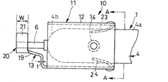
- FIG. 2 is a front view showing a part of a discharge tube with a cap (discharge lamp) according to Embodiment 1 of the present invention.
- FIG. 3 is a cross-sectional view of a part of the base and the glass tube taken along line AA in FIG. 2 without the lead connection portion in FIG. 4 is a cross-sectional view of a part of the glass tube and the base of FIG. 3 as seen from the line connecting 0 ° and 180 ° of FIG.
- FIG. 5 is a cross-sectional view of a part of the glass tube and the base of FIG. 3 as viewed from the line connecting 120 degrees and 300 degrees of FIG. FIG.
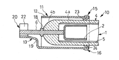
- FIG. 6 is a longitudinal sectional view of the discharge tube with cap shown in FIG.
- FIG. 7 is a cross-sectional view showing a holder and a substrate for mounting a part of the glass tube and base of FIG. 2 and a discharge tube with a base.
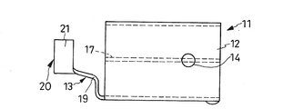
- FIG. 8 is a front view of the base of FIG.
- FIG. 9 is a plan view of the base of FIG.
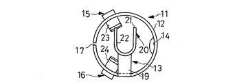
- FIG. 10 is a left side view of the base of FIG.
- FIG. 11 is a plan view showing a part of the first elastic holding portion of the base of FIG. 9 and a cylindrical portion in the vicinity thereof.
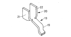
- 12 is an enlarged perspective view showing the lead connecting portion of FIG.
- FIG. 13 is a side view showing the hook-shaped portion and the lead of FIG. FIG.
- FIG. 14 is a plan view showing a base according to the second embodiment of the present invention.
- FIG. 15 is a left side view of the base of FIG. 16 is a cross-sectional view showing a part of the glass tube and the base at a position connecting 240 degrees and 60 degrees in FIG.
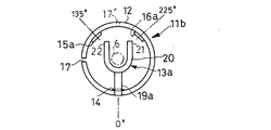
- FIG. 17 is a side view showing a base according to the third embodiment of the present invention.
- FIG. 18 is a cross-sectional view showing a part of a glass tube and a base according to Embodiment 4 of the present invention.
- FIG. 19 is a plan view showing a part of a base in Embodiment 5 of the present invention.
- 20 is a cross-sectional view showing a part of the base of FIG.
- a discharge tube with a cap according to the first embodiment, that is, a discharge lamp 10, is a CCFL, and is configured as shown in FIGS.
- the discharge lamp 10 comprises an assembly of a discharge tube 1 without a cap shown in FIG. 1 and a cap 11 shown in FIGS.
- the no-cap discharge tube 1 shown only partially in FIGS. 2 and 6 has the same configuration as the discharge tube shown by the same reference numeral in FIG.
- the discharge tube 1 without a cap has a pair of electrodes 2 and 3 and a cylindrical shape surrounding the pair of electrodes 2 and 3 and containing rare gas such as Ar and mercury.
- the glass tube 4 includes a main body portion 4a and a pair of closed portions (sealing portions) 4b.
- the blocking portion 4 b is made of glass beads and integrated with the main body portion 4 a of the glass tube 4.
- the base 11 surrounds a part of the main body 4 a and the closed part 4 b of the glass tube 4 and surrounds the entire electrode 2.
- the base 11 can be deformed so as to surround only part of the electrode 2 without surrounding it.
- the base 11 can be deformed so as not to surround the entire closed portion 4b of the glass tube 4 but to surround only a part of the closed portion 4b, or not to surround the closed portion 4b of the glass tube 4 at all. Since the glass tube 4 can transmit light, the light generated in the glass tube 4 is taken out from a portion of the main body 4a of the glass tube 4 that is not surrounded by the base 11.
- the base 11 is a metallic material having an inner diameter into which the glass tube 4 can be inserted.
- the protrusion 12 protrudes inward in the radial direction from the cylindrical portion 12 and protrudes inward in the radial direction from the cylindrical portion 12 so as to contact the outer peripheral surface of the glass tube 4 inserted into the cylindrical portion 12.
- first and second elastic holding portions 15 and 16 having portions.
- the cylindrical portion 12 of the base 11 has an inner diameter (for example, 7.7 mm) larger than the outer diameter (for example, 7.5 mm) of the glass tube 4 in order to insert the cylindrical glass tube 4, and this axial direction And a slit 17 extending in the direction. Accordingly, the cylindrical portion 12 is not a complete cylinder but a cylinder having a slit 17 extending from one end of the cylindrical portion 12 to the other end. Since the width of the slit 17 in the circumferential direction of the cylindrical portion 12 is, for example, 0.2 mm and is less than one tenth of the circumference of the cylindrical portion 12, the cylindrical portion 12 has a shape that can be regarded as a cylinder as a whole.
- the cylindrical portion 12 is formed by, for example, bending a metal plate having a thickness of 0.3 mm made of phosphor bronze whose surface is nickel-plated into an annular shape.
- the cylindrical portion 12 can also be formed of another metal plate (for example, a copper alloy plated with gold). Since the cylindrical portion 12 has the slit 17, it can be elastically deformed in this radial direction. However, in this embodiment, since the first and second elastic holding portions 15 and 16 are provided, the glass tube 4 can be inserted into the cylindrical portion 12 without elastic deformation of the cylindrical portion 12. . Therefore, the spring constant of the cylindrical portion 12 is larger than the spring constant of the first and second elastic holding portions 15 and 16.
- the axial length of the cylindrical portion 12 of this embodiment is, for example, 7 mm, and is determined so as to cover from the end portion 18 of the glass tube 4 to the right end of one electrode 2 as apparent from FIG. .
- the axial length of the cylindrical portion 12 can be changed to be shorter or longer than that in FIG.
- a lead connecting portion 13 for connecting the cylindrical portion 12 to the lead 6 of the base 11 is formed integrally with the cylindrical portion 12, and a U-shaped portion 19 and a U formed at the tip of the band-shaped portion 19. It consists of a letter-shaped bowl-shaped part 20.
- the strip portion 19 has a width of, for example, 0.5 to 1.0 mm, is led out from one end of the cylindrical portion 12 in the axial direction thereof, and is bent at a plurality of portions of the strip portion 19 so as to form a crank shape. Therefore, the belt-like portion 19 functions as a spring that can be elastically deformed in the radial direction of the cylindrical portion 12 and also functions as a spring that can be elastically deformed in the axial direction of the cylindrical portion 12.
- the belt-like portion 19 is arranged at a position shifted by 90 degrees from the positioning protrusion 14 in the circumferential direction of the cylindrical portion 12. However, as shown in FIG. 17 to be described later, the belt-like portion 19 can be arranged at the same angular position as the positioning protrusion 14.
- the hook-shaped portion 20 of the lead connecting portion 13 is disposed on the opposite side of the cylindrical portion 12 through the band-shaped portion 19 and is disposed opposite to the lead 6 with a gap (for example, 1.2 mm) slightly wider than the diameter of the lead 6. It has a pair of pieces 21 and 22 and is formed in a U shape.
- the axial width (length) W of the cylindrical portion 12 of the pair of pieces 21 and 22 is larger than the thickness t of the strip-like portion 19.
- the paired pieces 21 and 22 of the hook-like portion 20 are arranged symmetrically with respect to the belt-like portion 19 so as to be clamped between the leads 6 and are slightly elastically deformed in a direction of widening the mutual facing interval. It is possible to be formed. Further, as shown in FIG.
- the pair of pieces 21 and 22 extend in the same direction as the direction in which the belt-like portion 19 extends.
- the height position of the bowl-shaped portion 20 is set so that the lead 6 can be disposed therein.
- the pair of pieces 21 and 22 are plastically deformed in a direction approaching each other as shown in FIG. 12, and the lead 6 is sandwiched between the pair of pieces 21 and 22.
- electrical and mechanical coupling between the hook-shaped portion 20 and the lead 6 is established.
- a gap is provided between the lead 6 and the bottom of the U-shaped bowl-shaped portion 20 before being sandwiched.
- the flange 20 and the lead 6 are welded by laser in order to further strengthen the electrical and mechanical coupling between the flange 20 and the lead 6.
- the pair of pieces 21 and 22 can be welded together by laser.
- the lead connection portion 13 is formed by pressing a metal plate.
- the press working for the lead connection portion 13 is performed simultaneously with the press working (cutting) of the metal plate for forming the cylindrical portion 12.
- the hook-like portion 20 is obtained by bending a pair of pieces 21 and 22 obtained by pressing a metal plate into a U shape.
- a V-shaped portion for arranging the lead 6, a portion having a through hole for passing the lead 6, or the like can be provided.
- the positioning protrusion 14 provided on the cylindrical portion 12 is positioning means for determining the radial position of the glass tube 4 in the cylindrical portion 12.
- the positioning protrusion 14 as the positioning means protrudes in a hemispherical shape from the cylindrical portion 12 to the radially inner side of the cylindrical portion 12 so as to contact the outer peripheral surface of the glass tube 4 inserted into the cylindrical portion 12.
- the height of the protrusion of the positioning protrusion 14 from the cylindrical portion 12 is determined so as to allow the glass tube 4 to be inserted into the cylindrical portion 12, and is 0.1 mm, for example.
- the diameter of the positioning protrusion 14 in a plan view is, for example, 1 mm.
- the positioning protrusion 14 is formed at the same time as the press working for forming the cylindrical portion 12.
- the positioning protrusion 14 Since no slit is provided at the boundary between the positioning protrusion 14 and the cylindrical portion 12, the positioning protrusion 14 is not substantially elastically deformed. Therefore, the positioning protrusion 14 functions as a fixed positioning portion in the radial direction of the glass tube 4. Of course, it is possible to give elasticity to the positioning protrusion 14 so as to be elastically deformed within an allowable range of positional deviation in the radial direction of the glass tube 4. Since the positioning protrusion 14 protrudes in a hemispherical shape inside the cylindrical portion 12 in the radial direction, the frictional resistance between the positioning protrusion 14 and the glass tube 4 when the glass tube 4 is inserted is reduced, and the glass tube 4 can be inserted smoothly.
- the positioning protrusion 14 can be deformed into an ellipse or the like in a planar shape. As apparent from FIG. 3, the positioning protrusion 14 is disposed at an angular position farthest from the slit 17 in the circumferential direction of the cylindrical portion 12. That is, the positioning protrusion 14 is disposed at a position facing the slit 17. Since the cylindrical part 12 has the slit 17, it can be elastically deformed in the radial direction. At this time, the cylindrical portion 12 is deformed so as to widen the width of the slit 17, and the positioning protrusion 14 arranged at an angular position away from the slit 17 is not displaced and is closest to the slit 17 of the cylindrical portion 12. The part is displaced the most. Therefore, as shown in FIG. 3, the positioning protrusion 14 arranged at the angular position farthest from the slit 17 in the circumferential direction of the cylindrical portion 12 functions as an ideal positioning portion.
- the first and second elastic holding portions 15 and 16 provided integrally with the cylindrical portion 12 are elastic holding means for holding the glass tube 4 in the cylindrical portion 12 in cooperation with the positioning protrusion 14. It is.
- the first and second elastic holding portions 15 and 16 as elastic holding means can also be called first and second elastic holding pieces, extend in the axial direction of the cylindrical portion 12 and For example, it is a band-like piece having a width of 1 mm that is cantilevered and supported by the cylindrical portion 12, and protrudes radially inward from the cylindrical portion 12 to elastically hold the glass tube 4 inserted into the cylindrical portion 12. ing. As is clear from FIG.
- the height of the cylindrical portion 12 protruding inward in the radial direction of the first and second elastic holding portions 15 and 16 allows the glass tube 4 to be inserted into the cylindrical portion 12. And it is determined to press the glass tube 4 radially inward after insertion. That is, when the glass tube 4 is not inserted into the cylindrical portion 12, the diameter of a virtual circle (inscribed circle) that contacts the first and second elastic holding portions 15, 16 and the positioning protrusion 14 is the glass tube.
- the first and second elastic holding portions 15, 16 and the positioning protrusion 14 are formed to have the same diameter as the glass tube 4, the first and second elastic holding portions 15, 16 and the positioning protrusion 14 are formed.
- the height of the protrusion of the first and second elastic holding portions 15 and 16 from the cylindrical portion 12 is 0.2 mm, for example, and the positioning protrusion It is higher than the height of 14 protrusions.
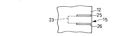
- the first and second elastic holding portions 15 and 16 have the same shape and are apparent from FIGS. 2, 3, 5, 6, 9, 10, and 11. Are formed in a substantially U shape, and have elastic holding pieces 23 and 24 projecting inside the cylindrical portion 12. As shown in FIG. 11, the first elastic holding portion 15 is partitioned from the cylindrical portion 12 by slits 25 and 26. As shown in FIG. 11, the second elastic holding portion 16 is also partitioned from the cylindrical portion 12 by slits similar to the slits 25 and 26.
- a metal strip for forming the cylindrical portion 12 is pressed to provide a longitudinal strip piece that is cantilevered. The tip of the strip is bent in a U shape inside the cylindrical portion 12.
- the first and second elastic holding portions that are cantilevered by the cylindrical portion 12 and extend in a direction away from the lead 6 in the axial direction of the cylindrical portion 12 and then bent or folded in a direction approaching the lead 6. 15,16 are obtained.
- the distal ends of the elastic holding pieces 23 and 24 of the first and second elastic holding portions 15 and 16 are more cylindrical than the predetermined positions on the outer peripheral surface of the glass tube 4 when the glass tube 4 is not inserted into the cylindrical portion 12. Protrudes inside. For this reason, when the glass tube 4 is inserted into the cylindrical portion 12, the tips of the elastic holding pieces 23 and 24 are displaced in a direction approaching the cylindrical portion 12. Therefore, the elastic holding pieces 23 and 24 have a function of a compression spring.
- the elastic holding pieces 23, 24 are inclined toward the bending point (right end) farthest from the tip (glass tube contact portion) closest to the lead 6 in the axial direction of the cylindrical portion 12, and the farthest bending point (right end). Is away from the glass tube 4. Therefore, the glass tube 4 can be smoothly inserted from the right end side to the left end side of the cylindrical portion 12.
- the first and second elastic holding portions 15 and 16 have a spring constant smaller than that of the positioning protrusion 14 and the cylindrical portion 12 in the radial direction of the cylindrical portion 12, and are higher than that of the positioning protrusion 14 and the cylindrical portion 12. Are also easily elastically deformed.
- the glass tube 4 can be inserted into the cylindrical portion 12 only by the elastic deformation of the first and second elastic holding portions 15 and 16 without being accompanied by the deformation of the positioning protrusion 14 and the cylindrical portion 12.
- the glass tube 4 is inserted into the cylindrical portion 12 with both the elastic deformation of the first and second elastic holding portions 15 and 16 and the elastic deformation of the cylindrical portion 12 in the radial direction by the slit 17. You can also.
- the first and second elastic holding portions 15 and 16 are disposed in an angular range of 90 to 270 degrees with respect to the positioning protrusion 14 in the circumferential direction of the cylindrical portion 12.
- the first elastic holding portion 15 is in the range of 90 ° to 180 ° (between 90 ° and the slit 17), more preferably in the range of 100 ° to 140 ° with respect to the positioning protrusion 14. It is desirable to arrange at 120 degrees in this embodiment.
- the second elastic holding portion 16 is arranged in a range of 180 degrees to 270 degrees (between the slits 17 and 270 degrees), more preferably in a range of 210 degrees to 260 degrees with respect to the positioning protrusion 14. In this embodiment, it is arranged at 240 degrees.
- a discharge tube 1 without a cap and a cap 11 are prepared.
- the base 11 has a direction from one end of the cylindrical portion 12 where the lead connecting portion 13 is not led out to the other end where the lead connecting portion 13 is led out.
- the capless discharge tube 1 is inserted into the cylindrical portion 12. Thereby, the positioning protrusion 14 and the first and second elastic holding portions 15 and 16 come into contact with the outer peripheral surface of the glass tube 4, and the glass tube 4 is held by these.
- the positioning protrusion 14 becomes a reference in the radial direction of the glass tube 4, and the first and second elastic holding portions 15 and 16 elastically hold the glass tube 4 so as to press the glass tube 4 against the positioning protrusion 14. Press. If the positioning protrusion 14 is also elastically deformable like the first and second elastic holding portions 15 and 16, the radial position of the glass tube 4 becomes unstable and is coaxial with the cylindrical portion 12. It becomes difficult to arrange the glass tube 4 on the surface. On the other hand, in the present embodiment, the radial position of the glass tube 4 is determined by the positioning protrusion 14 that is not elastically deformed or hardly elastically deformed, so that the glass tube 4 can be easily inserted coaxially into the cylindrical portion 12. become.
- the lead 6 can be accurately positioned with respect to the flange portion 20 of the lead connection portion 13.
- the pair of pieces 21 and 22 of the bowl-shaped portion 20 are plastically deformed in the direction approaching each other as described above, and the lead 6 is sandwiched between the pair of pieces 21 and 22.
- the pair of pieces 21 and 22 and the lead 6 or between the pair of pieces 21 and 22 or both of them are welded by laser.
- a discharge tube with a base that is, a discharge 10 or the like, in which the base 11 is attached to the glass tube 4 and the base 11 is electrically connected to the lead 6, is obtained.
- the discharge tube with a cap that is, the discharge lamp 10 is mounted on a metallic holder 33 fixed to a fixed substrate 30 shown in FIG.
- the holder 33 mechanically holds the discharge lamp 10 and electrically connects the discharge lamp 10 to a power source, and can also be called a connector.
- the holder 33 has a pair of spring pieces 31 and 32 for elastically holding the cylindrical portion 12 of the base 11 of the discharge lamp 10. Since the holder 33 is made of metal and is connected to a power source (not shown), when the cylindrical portion 12 of the base 11 of the discharge lamp 10 is brought into contact with the holder 33, the lead 6, 7 of the discharge lamp 10 is interposed. A voltage is applied and the discharge lamp 10 is turned on.
- the base 11 has a fixed or non-elastic positioning projection 14 and a first and second in addition to the metallic cylindrical portion 12 and the lead connecting portion 13 having an inner diameter into which the glass tube 4 can be inserted.
- Second elastic holding portions 15 and 16 are provided. Therefore, the first and second elastic holding portions are arranged such that the glass tube 4 is disposed in the cylindrical portion 12 with the positioning protrusion 14 as a reference, and the centers of the cylindrical portion 12 and the glass tube 4 coincide.
- Each of 15, 16 and the positioning protrusion 14 abuts on the glass tube 4, and the positioning of the glass tube 4 in the cylindrical portion 12 is accurately achieved.
- the first and second elastic holding portions 15 and 16 follow the thermal expansion. It is elastically deformed and the glass tube 4 can be stably held by the base 11.
- the first and second elastic holding portions 15 and 16 have elastic holding pieces 23 and 24 protruding inside the cylindrical portion 12, and the elastic holding pieces 23 and 24 are outer peripheral surfaces of the glass tube 4. Therefore, the glass tube 4 can be smoothly inserted into the cylindrical portion 12 of the base 11.
- the first elastic holding part 15 is arranged at 120 degrees within an angle range of 90 degrees to 180 degrees with respect to the positioning protrusion 14 in the circumferential direction of the cylindrical part 12, and the second elastic holding part Since 16 is disposed at 240 degrees within an angle range of 180 degrees to 270 degrees, the cylindrical portion 12 of the base 11 can be smoothly inserted into the glass tube 4 and can be stably disposed. it can.
- the cylindrical portion 12 can be elastically deformed in the radial direction based on the slit 17. For this reason, the first and second elastic holding portions 15 and 16 elastically hold the glass tube 4 with the help of the elastic deformation in the radial direction of the cylindrical portion 12 based on the slit 17.
- the spring strength of the first and second elastic holding portions 15 and 16 can be reduced by the amount of the spring strength of the cylindrical portion 12 based on the slit 17.
- the elastic deformation of the cylindrical portion 12 based on the slit 17 also occurs when the temperature of the glass tube 4 rises when the discharge lamp 10 is turned on and the glass tube 4 is thermally expanded in the radial direction, and the discharge lamp 10 is turned on. This contributes to stable holding of the glass tube 4 at the time.
- the slit 17 of the cylindrical portion 12 is disposed at a position of 180 degrees with respect to the positioning projection 14, the positioning projection 14 is provided even if the cylindrical portion 12 is elastically deformed based on the slit 17. Is not displaced, and the positioning function of the glass tube 4 is maintained.
- the lead 6 is disposed between the pair of pieces 21 and 22 of the hook-shaped portion 20 of the lead connecting portion 13 and the pair of pieces 21 and 22 is plastically deformed so as to sandwich the lead 6.
- An electrical and mechanical connection between 6 and the base is achieved. Therefore, the electrical and mechanical coupling between the lead 6 and the base can be easily and satisfactorily achieved. Further, when the base is electrically and mechanically coupled to the lead 6, the glass tube 4 is hardly damaged.
- the belt-like portion 19 of the lead connecting portion 13 is bent at a plurality of locations in a crank shape. Therefore, the belt-like portion 19 can be elastically deformed in both the radial direction and the axial direction of the cylindrical portion 12.
- the hook-like portion 20 is formed so as to sandwich the lead 6 by the pair of pieces 21 and 22 of the hook-like portion 20 of the lead connection portion 13, and the axial width (length) of the pair of pieces 21 and 22 ) W is formed wider (longer) than the thickness t, and the pair of pieces 21 and 22 are formed symmetrically, so that the pair of pieces 21 and 22 are deformed and the lead 6 can be clamped well and easily. can do.
- the band-like portion 19 of the lead connecting portion 13 is elastically deformed in the radial direction, so that the flange-like portion 20 of the lead connecting portion 13 and the lead 6 are well bonded. Kept.
- FIG. 14 to FIG. 16 the same reference numerals are given to substantially the same parts as those in FIG. 1 to FIG. In the description of the second embodiment, FIGS. 1 to 13 are referred to as necessary.
- the discharge tube with a cap or discharge lamp 10a according to the second embodiment a part of which is shown in FIG. 16, is configured in the same manner as the discharge tube with a cap or discharge lamp 10 of the first embodiment except for the deformed cap 11a.
- the base 11 a according to the second embodiment is configured in the same manner as the base 11 of the first embodiment except for the positions of the deformed first and second elastic holding portions 15 a and 16 a and the positioning protrusion 14.
- the first and second elastic holding portions 15a and 16a as the glass tube holding means of the base 11a according to the second embodiment have the same shape.
- the first elastic holding portion 15 a is defined by a pair of slits 25 a and 26 a extending in the axial direction of the cylindrical portion 12, and is elastically deformable by being cut and raised to the inside in the radial direction of the cylindrical portion 12. Consists of strips.
- the tip portion of the elastically deformable strip-like piece facilitates the insertion of the glass tube 4 into the cylindrical portion 12 and improves the contact of the first elastic holding portion 15a with the glass tube 4. It is bent outward in the axial direction. That is, as is apparent from FIG.
- the tip of the first elastic holding portion 15a made of a strip is separated from the glass tube 4 and is cantilevered by the cylindrical portion 12 of the first elastic holding portion 15a.
- the most protruding curved portion between the portion and the tip is in contact with the glass tube 4.
- the second elastic holding portion 16a not shown in detail is configured similarly to the first elastic holding portion 15a.
- the position in the axial direction of the cylindrical portion 12 of the positioning protrusion 14 of the base 11a according to the second embodiment (the position in the left-right direction in FIG. 14) is shifted to the right of the cylindrical portion 12 as compared with that of the first embodiment.
- the shift of the positioning protrusion 14 to the right is such that the positions (positions in the axial direction) of the first and second elastic holding portions 15a and 16a that are in contact with the glass tube 4 are moved to the right as compared with those in the first embodiment. It is based on the shift.
- the distance between the left end of the cylindrical portion 12 and the positioning protrusion 14 in FIG. 14 is such that the left end of the cylindrical portion 12 and the portions where the first and second elastic holding portions 15a and 16a abut against the glass tube 4 The distance between is almost the same.
- the position where the first and second elastic holding portions 15a, 16a abut on the glass tube 4 and the position where the positioning protrusion 14 abuts on the glass tube 4 are substantially the same.
- the positioning protrusion 14 and the first and second elastic holding portions 15 a and 16 a are arranged in this way, the axis of the glass tube 4 can be prevented from being inclined with respect to the axial direction of the cylindrical portion 16.
- the height of the protrusion from the cylindrical portion 12 of the positioning protrusion 14 and the first and second elastic holding portions 15a and 16a according to the second embodiment when the glass tube 4 is not inserted into the cylindrical portion 12 is as follows. Determined in the same manner as in Example 1. That is, in a state where the glass tube 4 is not inserted into the cylindrical portion 12, the diameter of the virtual circle inscribed in the positioning protrusion 14 and the first and second elastic holding portions 15a and 16a is the diameter of the glass tube 4. Is set smaller than.
- the second embodiment Since the positioning protrusion 14 according to the second embodiment and the first and second elastic holding portions 15a and 16a function in the same manner as those corresponding to those according to the first embodiment, the second embodiment is similar to the first embodiment. An effect can be obtained.
- FIG. 17 shows the left side surface of the base 11b as seen from the bowl-shaped part 20 side as in FIG.
- the deformed base 11b has the same configuration as the base 11a of the second embodiment except for the positions of the positioning protrusion 14 and the first and second elastic holding portions 15a and 16a.
- the positioning protrusion 14 is disposed at the same position (zero degree) as the derived angle position from the cylindrical portion 12 of the lead connecting portion 13a.
- the first elastic holding portion 15a is preferably arranged in the angular range of 90 to 180 degrees with respect to the positioning protrusion 14 in the circumferential direction of the cylindrical portion 12 as a reference (zero degree). In the embodiment of FIG. It is arranged at an angular position of 135 degrees.
- the second elastic holding portion 16a is preferably arranged in an angle range of 180 ° to 270 ° with the positioning protrusion 14 as a reference (zero degree). In the embodiment of FIG. 17, the second elastic holding portion 16a is arranged at an angular position of 225 °. Yes.
- the lead connection portion 13a in FIG. 17 has the strip-like portion 19a having a width of 0.5 mm that is slightly narrower than the strip-like portion 19 in the lead connection portion 13 of the first and second embodiments.
- the configuration is the same as that of the unit 13.
- the belt-like portion 19 a extends in the central direction of the cylindrical portion 12 from the arrangement angular position (zero degree) of the positioning protrusion 14.
- a U-shape having a pair of pieces 21 and 22, that is, a bowl-shaped portion 20 is provided at the tip of the strip-shaped portion 19 a.
- the pair of pieces 21 and 22 facing each other are formed so that they can be elastically deformed in the direction in which the mutual distance increases.
- Example 3 in FIG. 17 since the basic configuration of the base 11b of the third embodiment shown in FIG. 17 is the same as that of the base 11a according to the second embodiment, the same effects as those of the second embodiment can be obtained by the third embodiment shown in FIG.
- Example 3 in FIG. 17 since the angular position where the lead connecting portion 13 a is led out from the cylindrical portion 12 and the angular position of the positioning protrusion 14 are the same, the lead led out from the glass tube 4 is used. 6 can be accurately aligned with the hook-shaped portion 20 of the lead connecting portion 13a.
- Example 3 of FIG. 17 when the glass tube 4 is inserted into the cylindrical portion 12 of the base 11b, the first and second elastic holding portions 15a and 16a are disposed above the outer peripheral surface of the glass tube 4.
- the lead 6 is inserted between the pair of pieces 21 and 22 of the hook-like portion 20 of the lead connecting portion 13a.
- the lead 6 may be bent without extending linearly.
- the center of the lead 6 and the center of the pair of pieces 21 and 22 of the bowl-shaped portion 20 do not always coincide with each other.
- only one positioning protrusion 14 is disposed at the zero degree position, so that when the glass tube 4 is inserted into the cylindrical portion 12 of the base 11b, the glass It is possible that the tube 4 and the lead 6 are displaced in the lateral direction (horizontal direction) in FIG.
- the pair of pieces 21 and 22 of the bowl-shaped portion 20 can be displaced in the horizontal direction (horizontal direction) in FIG.
- the tube 4 can be inserted smoothly.
- the slit 17 is disposed at an angular position of 90 degrees with respect to the positioning protrusion 14. However, the slit 17 can be moved to a position (180 degrees) indicated by a broken line 17 'in FIG.
- the first elastic holding portion 15 a is disposed in the 0 to 180 degree section between the slit and the positioning protrusion 14
- the second elastic holding portion 16a is disposed in the 180 to 360 degree section between the positioning protrusion 14 and the positioning protrusion 14.
- a slit extending in the axial direction of the cylindrical portion 12 of the base 11 b enables elastic deformation of the cylindrical portion 12 in the radial direction. Therefore, the glass tube 4 is elastically held by the base 11b with both the elastic deformation of the first and second elastic holding portions 15a and 16a and the elastic deformation of the cylindrical portion 12 of the base 11b.
- the elasticity of the 1st and 2nd elastic holding parts 15a and 16a can be weakened compared with the case of the slit 17 of FIG. .
- the position of the positioning protrusion 14 of Example 1 shown in FIGS. 2 to 13 and the positions of the first and second elastic holding portions 15 and 16 are changed to the position of the positioning protrusion 14 shown in FIG. It can change to the position of the 1st and 2nd elastic holding
- a notch that bites into the cylindrical portion 12 in a semicircular shape can be provided at the boundary portion between the cylindrical portion 12 and the strip-shaped portion 19a.
- FIG. 18 shows a discharge lamp 10b according to the fourth embodiment as in FIG.
- the discharge lamp 10b according to the fourth embodiment is configured in the same manner as the discharge lamp 10 of the first embodiment except that the discharge lamp 10b has a deformed base 11c.
- the deformed base 11c of FIG. 18 is formed in the same manner as the base 11a of the first embodiment except for the first and second positioning protrusions 14a and 14b and the elastic holding part 15 ′.
- the first and second positioning protrusions 14a and 14b as positioning means in FIG. 18 have the same shape as the positioning protrusion 14 of the first embodiment and function as fixed positioning in the radial direction of the glass tube 4.
- the first and second positioning protrusions 14 a and 14 b are arranged with an angular interval of 120 degrees in the circumferential direction of the cylindrical portion 12.
- the angular interval between the first and second positioning protrusions 14a and 14b can be changed to an arbitrary angular interval selected from an angular interval smaller than 180 degrees.
- a preferred angular interval between the first and second positioning protrusions 14a and 14b is 60 to 120 degrees.
- the elastic holding portion 15 ′ can be modified to be the same as the first and second elastic holding portions 15 a and 16 a of the second embodiment.
- the deformed base 11d according to the fifth embodiment has the same configuration as that of the first embodiment except that the first and second elastic holding portions 15 and 16 of the base 11 according to the first embodiment are deformed.
- the deformed first elastic holding portion 15b according to the fifth embodiment is configured so that the belt-like body of the both ends supported by the pair of slits 25b and 26b extending in the axial direction of the cylindrical portion 12 is disposed radially inward of the cylindrical portion 12. Consists of protruding protrusions.
- the second elastic holding portion of the fifth embodiment (not shown) provided corresponding to the second elastic holding portion 16 of the first embodiment is configured in the same manner as the first elastic holding portion 15b of FIGS.
- the height of the cylindrical portion 12 protruding inward in the axial direction of the first elastic holding portion 15b of FIGS. 19 and 20 is determined in the same manner as the first and second elastic holding portions 15 and 16 of the first embodiment. ing.
- the positioning protrusion not shown in FIGS. 19 and 20 is formed in the same manner as the positioning protrusion 14 of the first embodiment.
- the first elastic holding portion 15b and the second elastic holding portion not shown in FIGS. 19 and 20 function in the same manner as the first and second elastic holding portions 15 and 16 of the first embodiment.
- the same effect as that of the first embodiment can be obtained also with 5. Note that the first and second elastic holding portions 15a and 16b in FIG. 17 can be modified to be the same as the first elastic holding portion 15b shown in FIGS.
- the present invention is not limited to the above-described embodiments, and for example, the following modifications are possible.
- the base of the present invention can be applied to another discharge tube having a shape similar to this other than the baseless cold cathode fluorescent discharge tube 1 shown in FIG.
- the slit 17 of the cylindrical portion 12 can be omitted, and the cylindrical portion 12 can be made into a cylinder without slit. When the slit 17 is omitted, the slit 17 of the cylindrical portion 12 is welded.
- the cylindrical portion 12 can be provided with a stopper for limiting the insertion position of the glass tube 4 in the cylindrical portion 12 in the axial direction.
- the number of bending portions of the strip portion 19 of the lead connection portion 13 can be increased or decreased. For example, the number of bending portions in the axial direction can be three or more.
- the discharge gas sealed in the glass tube 4 may be one or more selected from, for example, He, Ne, Ar, Kr, and Xe. Further, mercury gas sealed in the glass tube 4 can be omitted.
- Welding between the pair of pieces 21 and 22 and the lead 6 of the lead connecting portion 13 or between the pair of pieces 21 and 22 can be performed by welding using a method other than laser. Further, the pair of pieces 21 and 22 of the lead connection portion 13 and the lead 6 or the pair of pieces 21 and 22 can be coupled to each other using a conductive bonding material.
Landscapes
- Common Detailed Techniques For Electron Tubes Or Discharge Tubes (AREA)
- Vessels And Coating Films For Discharge Lamps (AREA)
Abstract
放電管に装着するための口金11は、放電管のガラス管4を挿入することができる内径を有する金属製の円筒状部12と、リード接続部と、円筒状部に形成された固定の位置決め突出部14と、ガラス管4の外周面に弾性的に当接する第1及び第2の弾性保持部15,16とを備えている。第1及び第2の弾性保持部15,16のそれぞれは位置決め突出部よりも弾性変形し易い形状に形成されている。固定の位置決め突出部14と第1及び第2の弾性保持部15,16との働きによって、ガラス管4が口金11の円筒状部12内の所定位置に正確に配置される。
Description
本発明は、例えば冷陰極蛍光放電灯即ちCCFL(Cold‐Cathode Fluorescent Lamp)等の放電灯、及びこの放電灯のための口金、及び口金付き放電管(放電灯)の製造方法に関する。
TVモニター、パソコン等の液晶表示装置のバックライト光源として使用する冷陰極蛍光放電灯(CCFL)は、例えば特開2007-234551号公報(特許文献1)等で公知である。図1に特許文献1に開示されたものと実質的に同一の口金無し冷陰極蛍光放電管1(以下、単に口金無し放電管と呼ぶ。)が示されている。この口金無し放電管1は、対の電極2,3と、該対の電極2,3を包囲し且つAr等の希ガス(レアガス)と水銀が封入された円筒状のガラス管4と、このガラス管4の内壁に形成された蛍光体層5と、ガラス管4の軸方向外側に導出された対のリード6,7とから成る。ガラス管4は円筒状の本体部4aとこの本体部4aの両端の閉塞部4bとから成る。図1において本体部4aと一体に示されている閉塞部(封止部)4bは、ガラスビーズ(リード6,7を伴ったガラス球)で形成されている。勿論、ガラスビーズを使用しないで閉塞部4bを形成することもできる。対のリード6,7は、対の電極2,3に接続され、対の閉塞部4bの中心からそれぞれ導出されている。対の電極2,3は実質的に同一の構成を有するが、これ等を互いに別な構成にすることもできる。
図1の口金無し放電管1を点灯させるためには、図示されていない電源から対のリード6,7に所定の電圧を印加しなければならない。口金無し放電管1を電源に容易に接続するために、例えば特許文献1に開示されているように、図1の口金無し放電管1に対して図示されていない対の口金が装着される。なお、口金は、ベース又はキャップ又はランプベース又はコネクタと呼ばれることもある。対の口金はリード6,7にそれぞれ接続される。本願では、口金付き放電管が放電灯と呼ばれている。口金付き放電管(放電灯)は、図示されていない基板又は固定板に配置されている対のコネクタ(ホルダー)に装着される。対のコネクタ(ホルダー)は電源に接続されているので、図1の口金無し放電管1の対のリード6,7は、対の口金と対のコネクタ(ホルダー)とを介して電源に接続される。対の口金はガラス管4の一部のみを覆い、ガラス管4の本体部4aの大部分を覆わないので、発生した光をガラス管4の外に取り出すことができる。
ところで、口金に対して、図1の口金無し放電管1に口金を装着する際のガラス管4の割れを防ぐことができこと、安定した放電を維持することができこと、放電灯のコストの低減を図ることができることが要求される。特許文献1に開示されている口金は、ガラス管4を覆う円筒状部(口金本体部)から導出された帯状導出部とこの帯状導出部の先端に形成されたリード接続部とを有する。前記帯状導出部は弾性変形可能に形成されているので、この帯状導出部は口金を口金無し放電管1に装着する時に口金側からリードに無理な力が加わることを防止し、ガラス管4の割れを防ぐ。また、特許文献1に開示されている口金の円筒状部は軸方向に延びるスリットを有し、その径方向に弾性変形することができる。これにより口金の円筒状部がガラス管4に弾性を有して接触し、ガラス管4の割れを防ぐ。また、特許文献1に開示されている口金は、この内周全部がガラス管4に接触しておらず、この円筒状部の内壁から突出する複数の凸部がガラス管4に接触している。このためガラス管4の熱が口金を通して逃げることが制限される。即ち、凸部のために生じたガラス管4と口金の円筒状部との間隙が断熱層として機能し、電極2,3の近傍の温度が安定化され、放電の安定化が図られる、放電の性能が向上する。また、特許文献1に開示されている口金は、金属板のプレス加工によって形成されているので、比較的低コストである。
しかし、特許文献1に開示されている口金は、口金の円筒状部の内壁から突出する複数の凸部の所望の弾性変位を良好に得ることが困難であるという問題、及び口金を口金無し放電管1に容易且つ正確に装着することが困難であるという問題を有する。
しかし、特許文献1に開示されている口金は、口金の円筒状部の内壁から突出する複数の凸部の所望の弾性変位を良好に得ることが困難であるという問題、及び口金を口金無し放電管1に容易且つ正確に装着することが困難であるという問題を有する。
図1の口金無し放電管1又はこれに類似の放電管に対する従来の別の口金が、WO2008/001565公開公報(特許文献2)に開示されている。この特許文献2に開示されている口金は、金属性の円筒状部(口金本体部)と、円筒状部(口金本体部)に設けた片持バネから成る複数の弾性保持片と、リードに対して円筒状部(口金本体部)を接続するために円筒状部から導出された帯状導出部と、この帯状導出部の先端に形成されたリード結合部とを有する。この特許文献2の複数の弾性保持片はガラス管に弾性的に当接する。従って、口金の円筒状部(口金本体部)の弾性変形に頼らないでガラス管に口金を弾性的に当接させることができる。
しかし、特許文献2に開示されている口金では、複数の弾性保持片の全てが弾性変形するので、複数の弾性保持片のバネ特性のバラツキがあると、口金の円筒状部(口金本体部)の中央にガラス管を配置することが困難になる。もし、ガラス管の中心と口金の中心とが不一致の場合には、放電管のリードが口金の中心と不一致となり、リードに不要な力が加わり、リード又はガラス管が損傷する虞がある。
上述から明らかなように従来の放電灯は、口金の円筒状部分(本体)内の所定位置にガラス管をより正確に且つ容易に配置することが困難であるという問題点を有している。従来の別な放電灯は、口金の円筒状部分(本体)内の所定位置にガラス管をより正確に且つ容易に配置することが困難であり、且つ放電管のリードに対して口金のリード接続部を良好に接続することが困難であるという問題点を有している。従って、本発明の目的は、上記問題点を解決することができる口金、及び口金付き放電管(放電灯)、及びその製造方法を提供することである。
上記課題を解決するための本発明は、電極と、該電極を包囲し且つ円筒状に形成されているガラス管と、前記電極に接続され且つ前記ガラス管の外側に導出されているリードとを有する放電管に対して装着するための口金に係わるものである。本発明に従う口金は、前記ガラス管の外径よりも大きい内径を有する金属製の円筒状部と、前記リードに前記円筒状部を接続するために前記円筒状部から導出されたリード接続部と、前記円筒状部の中における前記ガラス管の径方向位置を決めるために前記円筒状部の内周側に配置された位置決め手段と、前記位置決め手段と共同して前記円筒状部の中に前記ガラス管を保持するためのものであって、前記円筒状部の内周側に配置され且つ前記位置決め手段よりも弾性変形し易い形状を有している保持手段とを備えている。
前記位置決め手段は、前記円筒状部に挿入された前記ガラス管の外周面に当接するように前記円筒状部から該円筒状部の径方向内側に突出し、且つ前記ガラス管を前記円筒状部の中に位置決めするために弾性変形しない又は弾性変形し難い形状に形成された位置決め突出部であり、前記保持手段は、前記円筒状部に挿入された前記ガラス管の外周面に当接するように前記円筒状部から該円筒状部の径方向内側に突出し、且つ前記ガラス管を弾性的に保持するために前記位置決め突出部よりも弾性変形し易い形状に形成されている弾性保持部であることが望ましい。
前記位置決め突出部は、前記円筒状部を形成するための金属板の一部を塑性変形することによって形成された突起であることが望ましい。
前記弾性保持部は、前記円筒状部の軸方向に延びており且つ前記円筒状部に片持支持されており且つ弾性変形可能に形成されている帯状片から成ることが望ましい。
前記位置決め手段は、前記円筒状部に挿入された前記ガラス管の外周面に当接するように前記円筒状部から該円筒状部の径方向内側に突出し、且つ前記ガラス管を前記円筒状部の中に位置決めするために弾性変形しない又は弾性変形し難い形状に形成された位置決め突出部であり、前記保持手段は第1及び第2の弾性保持部であることが望ましい。前記第1及び第2の弾性保持部のそれぞれは、前記円筒状部に挿入された前記ガラス管の外周面に当接するように前記円筒状部から該円筒状部の径方向内側に突出し、且つ前記ガラス管を弾性的に保持するために前記位置決め突出部よりも弾性変形し易い形状に形成されていることが望ましい。前記第2の弾性保持部は、前記円筒状部の周方向において前記位置決め突出部を基準にして前記第1の弾性保持部に対して反対側になるように配置されていることが望ましい。
前記位置決め手段を、第1及び第2の位置決め突出部で構成することができる。前記第1及び第2の位置決め突出部のそれぞれは、前記円筒状部に挿入された前記ガラス管の外周面に当接するように前記円筒状部から該円筒状部の径方向内側に突出し、且つ前記ガラス管を前記円筒状部の中に位置決めするために弾性変形しない又は弾性変形し難い形状に形成されていることが望ましい。前記第1及び第2の位置決め突出部を有する口金における前記保持手段は、前記円筒状部に挿入された前記ガラス管の外周面に当接するように前記円筒状部から該円筒状部の径方向内側に突出し、且つ前記ガラス管を弾性的に保持するために前記第1及び第2の位置決め突出部よりも弾性変形し易い形状に形成された弾性保持部であることが望ましい。前記第1及び第2の位置決め突出部は、前記円筒状部の周方向において互いに180度よりも小さい角度間隔を有するように配置されていることが望ましい。前記弾性保持部は前記円筒状部の周方向において前記第1及び第2の位置決め突出部の中間角度位置を基準にして90度から270度の角度範囲に配置されていることが望ましい。
前記口金の前記円筒状部は、該円筒状部の軸方向に延びるスリットを有していることが望ましい。
前記リード接続部は、前記円筒状部から導出された帯状部と、該帯状部の先端に設けられた前記リードを結合するための対の片とを備えていることが望ましい。前記対の片は前記リードの径よりも大きい相互間隔を有して対向配置されていることが望ましい。前記円筒状部の軸方向における前記対の片のそれぞれの幅は前記対の片のそれぞれの厚みよりも広いことが望ましい。
前記帯状部は複数の屈曲箇所を有していることが望ましい。
前記リード接続部の前記帯状部は、前記円筒状部の周方向において前記位置決め突出部と同一の角度位置から導出され、且つ前記第1及び第2の弾性保持部の中間の角度位置に向って伸びていることが望ましい。
放電灯を製造するために、電極と、該電極を包囲し且つ円筒状に形成されているガラス管と、前記電極に接続され且つ前記ガラス管の外側に導出されているリードとを有する放電管を用意する工程と、
前記ガラス管の外径よりも大きい内径を有する金属製の円筒状部と、前記リードに前記円筒状部を接続するために前記円筒状部から導出されたリード接続部と、前記円筒状部の中における前記ガラス管の径方向位置を決めるために前記円筒状部の内周側に配置された位置決め手段と、前記位置決め手段と共同して前記円筒状部の中に前記ガラス管を保持するためのものであって、前記円筒状部の内周側に配置され且つ前記位置決め手段よりも弾性変形し易い形状を有している保持手段とを備えている口金を用意する工程と、
前記位置決め手段及び前記保持手段の働きにより前記口金の前記円筒状部の中に前記ガラス管が位置決めされ且つ保持されるように、前記口金の前記円筒状部の中に前記ガラス管を挿入する工程と、
前記リードを前記口金の前記リード接続部に電気的に接続する工程と
を備えていることが望ましい。
前記リード接続部は樋状部を有し、該樋状部は互いに対向配置された対の片を有していることが望ましい。この場合において、前記リードを前記口金の前記リード接続部に電気的に接続するために、前記樋状部の対の片の間に前記リードを配置し且つ前記リードを挟持するように前記対の片を変形させる工程と、前記対の片と前記リードとの間又は前記対の片の相互間を溶着する工程とを有していることが望ましい。
なお、本願において、位置決め突出部よりも弾性変形し易い形状に形成された弾性保持部とは、弾性保持部に単位荷重(力)を加えた時の変形(歪)量が、位置決め突出部に単位荷重(力)を加えた時の変形(歪)量よりも大きいことを意味している。要するに、位置決め突出部よりも弾性変形し易い形状に形成された弾性保持部とは、弾性保持部のバネ定数が位置決め突出部のバネ定数よりも小さいことを意味している。ここでのバネ定数は、バネに加える荷重(力)をF、バネの変形量をxとした時におけるF=kxの式における定数kを意味する。
前記位置決め突出部は、前記円筒状部を形成するための金属板の一部を塑性変形することによって形成された突起であることが望ましい。
前記弾性保持部は、前記円筒状部の軸方向に延びており且つ前記円筒状部に片持支持されており且つ弾性変形可能に形成されている帯状片から成ることが望ましい。
前記位置決め手段は、前記円筒状部に挿入された前記ガラス管の外周面に当接するように前記円筒状部から該円筒状部の径方向内側に突出し、且つ前記ガラス管を前記円筒状部の中に位置決めするために弾性変形しない又は弾性変形し難い形状に形成された位置決め突出部であり、前記保持手段は第1及び第2の弾性保持部であることが望ましい。前記第1及び第2の弾性保持部のそれぞれは、前記円筒状部に挿入された前記ガラス管の外周面に当接するように前記円筒状部から該円筒状部の径方向内側に突出し、且つ前記ガラス管を弾性的に保持するために前記位置決め突出部よりも弾性変形し易い形状に形成されていることが望ましい。前記第2の弾性保持部は、前記円筒状部の周方向において前記位置決め突出部を基準にして前記第1の弾性保持部に対して反対側になるように配置されていることが望ましい。
前記位置決め手段を、第1及び第2の位置決め突出部で構成することができる。前記第1及び第2の位置決め突出部のそれぞれは、前記円筒状部に挿入された前記ガラス管の外周面に当接するように前記円筒状部から該円筒状部の径方向内側に突出し、且つ前記ガラス管を前記円筒状部の中に位置決めするために弾性変形しない又は弾性変形し難い形状に形成されていることが望ましい。前記第1及び第2の位置決め突出部を有する口金における前記保持手段は、前記円筒状部に挿入された前記ガラス管の外周面に当接するように前記円筒状部から該円筒状部の径方向内側に突出し、且つ前記ガラス管を弾性的に保持するために前記第1及び第2の位置決め突出部よりも弾性変形し易い形状に形成された弾性保持部であることが望ましい。前記第1及び第2の位置決め突出部は、前記円筒状部の周方向において互いに180度よりも小さい角度間隔を有するように配置されていることが望ましい。前記弾性保持部は前記円筒状部の周方向において前記第1及び第2の位置決め突出部の中間角度位置を基準にして90度から270度の角度範囲に配置されていることが望ましい。
前記口金の前記円筒状部は、該円筒状部の軸方向に延びるスリットを有していることが望ましい。
前記リード接続部は、前記円筒状部から導出された帯状部と、該帯状部の先端に設けられた前記リードを結合するための対の片とを備えていることが望ましい。前記対の片は前記リードの径よりも大きい相互間隔を有して対向配置されていることが望ましい。前記円筒状部の軸方向における前記対の片のそれぞれの幅は前記対の片のそれぞれの厚みよりも広いことが望ましい。
前記帯状部は複数の屈曲箇所を有していることが望ましい。
前記リード接続部の前記帯状部は、前記円筒状部の周方向において前記位置決め突出部と同一の角度位置から導出され、且つ前記第1及び第2の弾性保持部の中間の角度位置に向って伸びていることが望ましい。
放電灯を製造するために、電極と、該電極を包囲し且つ円筒状に形成されているガラス管と、前記電極に接続され且つ前記ガラス管の外側に導出されているリードとを有する放電管を用意する工程と、
前記ガラス管の外径よりも大きい内径を有する金属製の円筒状部と、前記リードに前記円筒状部を接続するために前記円筒状部から導出されたリード接続部と、前記円筒状部の中における前記ガラス管の径方向位置を決めるために前記円筒状部の内周側に配置された位置決め手段と、前記位置決め手段と共同して前記円筒状部の中に前記ガラス管を保持するためのものであって、前記円筒状部の内周側に配置され且つ前記位置決め手段よりも弾性変形し易い形状を有している保持手段とを備えている口金を用意する工程と、
前記位置決め手段及び前記保持手段の働きにより前記口金の前記円筒状部の中に前記ガラス管が位置決めされ且つ保持されるように、前記口金の前記円筒状部の中に前記ガラス管を挿入する工程と、
前記リードを前記口金の前記リード接続部に電気的に接続する工程と
を備えていることが望ましい。
前記リード接続部は樋状部を有し、該樋状部は互いに対向配置された対の片を有していることが望ましい。この場合において、前記リードを前記口金の前記リード接続部に電気的に接続するために、前記樋状部の対の片の間に前記リードを配置し且つ前記リードを挟持するように前記対の片を変形させる工程と、前記対の片と前記リードとの間又は前記対の片の相互間を溶着する工程とを有していることが望ましい。
なお、本願において、位置決め突出部よりも弾性変形し易い形状に形成された弾性保持部とは、弾性保持部に単位荷重(力)を加えた時の変形(歪)量が、位置決め突出部に単位荷重(力)を加えた時の変形(歪)量よりも大きいことを意味している。要するに、位置決め突出部よりも弾性変形し易い形状に形成された弾性保持部とは、弾性保持部のバネ定数が位置決め突出部のバネ定数よりも小さいことを意味している。ここでのバネ定数は、バネに加える荷重(力)をF、バネの変形量をxとした時におけるF=kxの式における定数kを意味する。
本願の発明に従う口金は、ガラス管を挿入することができる内径を有する金属製の円筒状部、リード接続部、位置決め手段及び保持手段を有している。前記位置決め手段は前記円筒状部の中における前記ガラス管の径方向位置を決めるために前記円筒状部の内周側に配置されている。前記保持手段は前記位置決め手段と共同して前記円筒状部の中に前記ガラス管を保持するために、前記円筒状部の内周側に配置され且つ前記位置決め手段よりも弾性変形し易い形状を有している。前記位置決め手段と前記保持手段とを使用してガラス管を円筒状部内に配置すると、前記位置決め手段を基準にしてガラス管が円筒状部内に配置され、ガラス管の円筒状部内における位置決めが正確に達成される。
次に、図面を参照して本発明の実施形態に従う口金及びこれを装着した口金付き放電管即ち放電灯を説明する。
実施例1に従う口金付き放電管即ち放電灯10はCCFLであって、図2~図6に示すように構成されている。この放電灯10は、図1に示す口金無し放電管1と、図8~図10に示す口金11との組立体から成る。図2及び図6に一部のみが示されている口金無し放電管1は図1で同一符号で示されている放電管と同一に構成されている。口金無し放電管1は、図1において既に説明したように対の電極2,3と、該対の電極2,3を包囲し且つAr等の希ガス(レアガス)と水銀が封入された円筒状のガラス管4と、このガラス管4の内壁に形成された蛍光体層5と、ガラス管4の軸方向外側に導出された対のリード6,7とを備えている。ガラス管4は、本体部4aと対の閉塞部(封止部)4bとを備えている。例えば閉塞部4bはガラスビーズで構成され、ガラス管4の本体部4aに一体化されている。
図2~図6においては、図示を簡略化するために図1の一方の電極2に接続された一方のリード6に対する一方の口金11のみが示され、図1の他方の電極3に接続された他方のリード7に対する他方の口金の図示が省略されている。しかし、図1の他方のリード7に対しても一方のリード6に対する一方の口金11と同一形状の口金が接続されている。なお、放電管1の対のリード6、7に対して同一形状の口金を接続する代りに、互いに異なる形状の口金を接続することもできる。
図6において、口金11は、ガラス管4の本体部4aの一部と閉塞部4bとを包囲し且つ電極2の全部を包囲している。しかし、電極2の全部を包囲しないで一部のみを包囲するように口金11を変形することができる。また、ガラス管4の閉塞部4bの全部を包囲しないでその一部のみを包囲するように、又はガラス管4の閉塞部4bを全く包囲しないように、口金11を変形することができる。ガラス管4は光透過可能であるので、ガラス管4内で発生した光はガラス管4の本体部4aの口金11で包囲されていない部分から外に取り出される。
口金11は、口金付き放電管即ち放電灯10を示す図2~図7及び口金11のみを示す図8~図10から明らかなように、ガラス管4を挿入することができる内径を有する金属性の円筒状部(口金本体部)12と、リード6に円筒状部12を接続するためのリード接続部13と、円筒状部12に挿入されたガラス管4の外周面に当接するように円筒状部12からこの径方向内側に突出している位置決め突出部14と、円筒状部12に挿入されたガラス管4の外周面に当接するように円筒状部12からこの径方向内側に突出している部分を有する第1及び第2の弾性保持部15,16とを備えている。
口金11の円筒状部12は、円筒状のガラス管4を挿入するためにガラス管4の外径(例えば7.5mm)よりも大きい内径(例えば7.7mm)を有し、且つこの軸方向に延びているスリット17を有している。従って、円筒状部12は完全な円筒では無く、円筒状部12の一端から他端まで延びているスリット17を有する円筒である。円筒状部12の円周方向におけるスリット17の幅は例えば0.2mmであり、円筒状部12の円周の数十分の1以下であるので、円筒状部12は全体として円筒と見なせる形状を有する。円筒状部12は、例えば表面にニッケルメッキが施された燐青銅から成る厚み0.3mmの金属板を環状に曲げ加工することによって形成されている。勿論、円筒状部12を別の金属板(例えば金メッキが施された銅合金)で形成することもできる。円筒状部12はスリット17を有するので、この径方向に弾性変形可能である。しかし、この実施例では第1及び第2の弾性保持部15,16が設けられているので、円筒状部12の弾性変形を伴わないでもガラス管4を円筒状部12に挿入することができる。従って、円筒状部12のバネ定数は第1及び第2の弾性保持部15,16のバネ定数よりも大きい。この実施例の円筒状部12の軸方向の長さは例えば7mmであり、図6から明らかなようにガラス管4の端部18から一方の電極2の右端までを覆うように決定されている。しかし、円筒状部12の軸方向の長さを、図6よりも短く又は長くなるように変えることもできる。
口金11のリード6に円筒状部12を接続するためのリード接続部13は、円筒状部12と一体に形成されたものであり、帯状部19とこの帯状部19の先端に形成されたU字状の樋状部20とから成る。帯状部19は例えば0.5~1.0mmの幅を有して円筒状部12の一端からその軸方向に導出され、クランク状になるように帯状部19の複数箇所で屈曲されている。従って、帯状部19は円筒状部12の径方向に弾性変形可能なバネとして機能すると共に円筒状部12の軸方向に弾性変形可能なバネとしても機能する。図10において帯状部19は円筒状部12の周方向において位置決め突出部14から90度ずれた位置に配置されている。しかし、後述する図17に示すように帯状部19を位置決め突出部14と同一の角度位置に配置することもできる。
リード接続部13の樋状部20は帯状部19を介して円筒状部12と反対側に配置され且つリード6の径よりも少し広い間隔(例えば1.2mm)を有して対向配置された対の片21,22を有し、U字状に形成されている。対の片21,22の円筒状部12の軸方向の幅(長さ)Wは帯状部19の厚みtよりも大きい。この樋状部20の対の片21,22は、リード6に良好に挟持させるために帯状部19を中心にして左右対称に配置され、且つ相互の対向間隔を広げる方向に僅かに弾性変形することが可能に形成されている。また、対の片21,22は、図10に示すように帯状部19が延びる方向と同一方向に延びている。樋状部20の高さ位置はこの中にリード6を配置することができるように設定されている。リード6が樋状部20に配置された後に図12に示すように対の片21,22を互いに接近する方向に塑性変形させて対の片21,22でリード6を挟持する。これにより樋状部20とリード6との電気的及び機械的結合が成立する。なお、図2で示すように挟持する前において、リード6とU字状の樋状部20の底部との間に隙間が設けられている。また、この実施例では樋状部20とリード6との電気的及び機械的結合を更に強固にするために樋状部20とリード6とがレーザーによって溶接されている。なお、対の片21,22同士をレーザーによって溶接することもできる。
リード接続部13は金属板をプレス加工することによって形成されている。リード接続部13のためのプレス加工は、円筒状部12を形成するための金属板のプレス加工(切断)と同時に行われる。樋状部20は、金属板のプレス加工によって得られた対の片21,22をU字状に屈曲させることによって得られる。なお、樋状部20の代わりに、リード6を配置するためのV字状部、又はリード6を通すための貫通孔を有する部分等を設けることもできる。
円筒状部12に設けられた位置決め突出部14は、円筒状部12の中におけるガラス管4の径方向位置を決めるための位置決め手段である。この位置決め手段としての位置決め突出部14は、円筒状部12に挿入されたガラス管4の外周面に当接するように円筒状部12から円筒状部12の径方向内側に半球状に突出している。位置決め突出部14の円筒状部12からの突出の高さはガラス管4の円筒状部12への挿入を許すように決定され、例えば0.1mmである。また、位置決め突出部14の平面的に見た直径は例えば1mmである。この位置決め突出部14は円筒状部12を形成するためのプレス加工時に同時に形成されている。位置決め突出部14と円筒状部12との境界にスリットが設けられていないので、位置決め突出部14は実質的に弾性変形しない。従って、位置決め突出部14はガラス管4の径方向における固定の位置決め部として機能する。勿論、ガラス管4の径方向における位置のずれの許容範囲において弾性変形するように位置決め突出部14に弾性を与えることもできる。位置決め突出部14は円筒状部12の径方向内側に半球状に突出しているので、ガラス管4を挿入する時における位置決め突出部14とガラス管4との間の摩擦抵抗が小さくなり、ガラス管4を円滑に挿入することができる。なお、位置決め突出部14を平面形状において楕円形等に変形することもできる。
図3から明らかなように位置決め突出部14は円筒状部12の周方向においてスリット17から最も離れた角度位置に配置されている。即ち、位置決め突出部14はスリット17に対向する位置に配置されている。円筒状部12はスリット17を有するので、その径方向に弾性変形可能である。この時、円筒状部12はスリット17の幅を広げるように変形し、スリット17から離れた角度位置に配置されている位置決め突出部14は変位せず、円筒状部12のスリット17に最も近い部分が最も大きく変位する。従って、図3に示すように円筒状部12の周方向においてスリット17から最も離れた角度位置に配置された位置決め突出部14は理想的な位置決め部として機能する。
図3から明らかなように位置決め突出部14は円筒状部12の周方向においてスリット17から最も離れた角度位置に配置されている。即ち、位置決め突出部14はスリット17に対向する位置に配置されている。円筒状部12はスリット17を有するので、その径方向に弾性変形可能である。この時、円筒状部12はスリット17の幅を広げるように変形し、スリット17から離れた角度位置に配置されている位置決め突出部14は変位せず、円筒状部12のスリット17に最も近い部分が最も大きく変位する。従って、図3に示すように円筒状部12の周方向においてスリット17から最も離れた角度位置に配置された位置決め突出部14は理想的な位置決め部として機能する。
円筒状部12に一体に設けられた第1及び第2の弾性保持部15,16は、位置決め突出部14と共同して円筒状部12の中にガラス管4を保持するための弾性保持手段である。弾性保持手段としての第1及び第2の弾性保持部15,16は、第1及び第2の弾性保持片とも呼ぶことができるものであって、円筒状部12の軸方向に延びており且つ円筒状部12に片持支持されている例えば幅1mmの帯状片から成り、円筒状部12に挿入されたガラス管4を弾性的に保持するために円筒状部12からその径方向内側に突出している。図3から明らかなように、第1及び第2の弾性保持部15,16の円筒状部12の径方向内側への突出の高さは、ガラス管4の円筒状部12への挿入を許し且つ挿入後にガラス管4を径方向内側に押圧するように決定されている。即ち、円筒状部12にガラス管4を挿入していない状態において第1及び第2の弾性保持部15,16と位置決め突出部14とに接触する仮想円(内接円)の径がガラス管4の径よりも小さく、円筒状部12にガラス管4を挿入した状態において第1及び第2の弾性保持部15,16と位置決め突出部14とに接触する仮想円(内接円)の径がガラス管4の径と同一になるように、第1及び第2の弾性保持部15,16と位置決め突出部14が形成されている。円筒状部12にガラス管4を挿入していない状態においての第1及び第2の弾性保持部15,16の円筒状部12からの突出の高さは、例えば0.2mmあり、位置決め突出部14の突出の高さよりも高い。
更に詳しく説明すると、第1及び第2の弾性保持部15,16は互いに同一の形状を有し、図2、図3、図5、図6、図9、図10及び図11から明らかなように略U字状に形成され、円筒状部12の内側に突出した弾性保持片23,24を有する。第1の弾性保持部15は図11に示すように円筒状部12からスリット25、26で区画されている。第2の弾性保持部16も図11に示すようにスリット25、26と同様なスリットによって円筒状部12から区画されている。
U字状の第1及び第2の弾性保持部15,16を形成する時には、円筒状部12を形成するための金属板をプレス加工して片持支持された長手の帯状片を設け、この帯状片の先端部を円筒状部12の内側にU字状に屈曲する。これにより、円筒状部12に片持支持され且つ円筒状部12の軸方向においてリード6から離れる方向に延びた後にリード6に近づく方向に屈曲即ち折り返しされた第1及び第2の弾性保持部15,16が得られる。
第1及び第2の弾性保持部15,16の弾性保持片23,24の先端はガラス管4を円筒状部12に挿入しない状態においてガラス管4の外周面の予定位置よりも円筒状部12の内側に突出している。このため、円筒状部12にガラス管4が挿入された時には弾性保持片23,24の先端が円筒状部12に近づく方向に変位する。従って、弾性保持片23,24は圧縮バネの機能を有する。弾性保持片23,24は、円筒状部12の軸方向においてリード6から最も近い先端(ガラス管当接部)から最も遠い屈曲点(右端)に向って傾斜し、最も遠い屈曲点(右端)はガラス管4から離れている。従って、ガラス管4を円筒状部12の右端側から左端側に向って円滑に挿入することができる。第1及び第2の弾性保持部15,16は、円筒状部12の径方向において位置決め突出部14及び円筒状部12よりも小さいバネ定数を有し、位置決め突出部14及び円筒状部12よりも弾性変形し易い。このため、位置決め突出部14及び円筒状部12の変形を伴わないで第1及び第2の弾性保持部15,16の弾性変形のみでもガラス管4を円筒状部12に挿入することができる。勿論、第1及び第2の弾性保持部15,16の弾性変形とスリット17による円筒状部12の径方向の弾性変形との両方を伴なってガラス管4を円筒状部12に挿入することもできる。
U字状の第1及び第2の弾性保持部15,16を形成する時には、円筒状部12を形成するための金属板をプレス加工して片持支持された長手の帯状片を設け、この帯状片の先端部を円筒状部12の内側にU字状に屈曲する。これにより、円筒状部12に片持支持され且つ円筒状部12の軸方向においてリード6から離れる方向に延びた後にリード6に近づく方向に屈曲即ち折り返しされた第1及び第2の弾性保持部15,16が得られる。
第1及び第2の弾性保持部15,16の弾性保持片23,24の先端はガラス管4を円筒状部12に挿入しない状態においてガラス管4の外周面の予定位置よりも円筒状部12の内側に突出している。このため、円筒状部12にガラス管4が挿入された時には弾性保持片23,24の先端が円筒状部12に近づく方向に変位する。従って、弾性保持片23,24は圧縮バネの機能を有する。弾性保持片23,24は、円筒状部12の軸方向においてリード6から最も近い先端(ガラス管当接部)から最も遠い屈曲点(右端)に向って傾斜し、最も遠い屈曲点(右端)はガラス管4から離れている。従って、ガラス管4を円筒状部12の右端側から左端側に向って円滑に挿入することができる。第1及び第2の弾性保持部15,16は、円筒状部12の径方向において位置決め突出部14及び円筒状部12よりも小さいバネ定数を有し、位置決め突出部14及び円筒状部12よりも弾性変形し易い。このため、位置決め突出部14及び円筒状部12の変形を伴わないで第1及び第2の弾性保持部15,16の弾性変形のみでもガラス管4を円筒状部12に挿入することができる。勿論、第1及び第2の弾性保持部15,16の弾性変形とスリット17による円筒状部12の径方向の弾性変形との両方を伴なってガラス管4を円筒状部12に挿入することもできる。
第1及び第2の弾性保持部15、16は、図3から明らかなように円筒状部12の周方向において位置決め突出部14を基準にして90度から270度の角度範囲に配置されることが望ましい。更に詳しく説明すると、第1の弾性保持部15は、位置決め突出部14を基準にして90度~180度の範囲(90度とスリット17との間)、より好ましくは100度~140度の範囲に配置されることが望ましく、この実施例では120度に配置されている。第2の弾性保持部16は、位置決め突出部14を基準にして180度~270度の範囲(スリット17と270度との間)、より好ましくは210度~260度の範囲に配置されることが望ましく、この実施例では240度に配置されている。
図2~図7に示す口金付き放電管即ち放電灯10を製造する時には、口金無し放電管1と口金11とを用意する。次に、口金11の円筒状部12のリード接続部13が導出されていない側の一方の端からリード接続部13が導出された側の他方の端に向う方向性を有して口金11の円筒状部12の中に口金無し放電管1を挿入する。これにより、ガラス管4の外周面に対して位置決め突出部14、第1及び第2の弾性保持部15,16が当接し、これ等によってガラス管4が保持される。この時、位置決め突出部14がガラス管4の径方向の基準となり、位置決め突出部14にガラス管4を押し付けるように第1及び第2の弾性保持部15,16がガラス管4を弾性的に押圧する。もし、位置決め突出部14も第1及び第2の弾性保持部15,16と同様に弾性変形可能であれば、ガラス管4の径方向の位置が不安定になり、円筒状部12に同軸的にガラス管4を配置することが困難になる。これに対し、本実施例では、弾性変形しない又は弾性変形し難い位置決め突出部14によってガラス管4の径方向位置が決まるので、ガラス管4を円筒状部12に同軸的に挿入することが容易になる。また、ガラス管4を円筒状部12に同軸的に挿入することができるので、リード6をリード接続部13の樋状部20に対して正確に位置決めすることが可能になる。
次に、樋状部20の対の片21、22を既に説明したように互いに接近する方向に塑性変形させて、この対の片21、22でリード6を挟持する。しかる後、対の片21、22とリード6との間、又は対の片21、22の相互間、又はこれらの両方をレーザーによって溶接する。これにより、ガラス管4に口金11が装着され且つリード6に口金11が電気的に接続された口金付き放電管即ち放電等10が得られる。
次に、樋状部20の対の片21、22を既に説明したように互いに接近する方向に塑性変形させて、この対の片21、22でリード6を挟持する。しかる後、対の片21、22とリード6との間、又は対の片21、22の相互間、又はこれらの両方をレーザーによって溶接する。これにより、ガラス管4に口金11が装着され且つリード6に口金11が電気的に接続された口金付き放電管即ち放電等10が得られる。
口金付き放電管即ち放電灯10は例えば図7に示す固定基板30に固着された金属性のホルダー33に装着される。ホルダー33は放電灯10を機械的に保持し且つ放電灯10を電源に電気的に接続するものであり、コネクタとよぶこともできるものである。ホルダー33は放電灯10の口金11の円筒状部12を弾性的に保持するための対のバネ片31,32を有する。ホルダー33は金属製であり、且つ図示されていない電源に接続されているので、ホルダー33に放電灯10の口金11の円筒状部12を接触させると、放電灯10のリード6、7間に電圧が印加され、放電灯10が点灯する。
本実施例は次の効果を有する。
(1)口金11は、ガラス管4を挿入することができる内径を有する金属製の円筒状部12及びリード接続部13の他に、固定的即ち非弾性的な位置決め突出部14と第1及び第2の弾性保持部15,16とを備えている。このため、位置決め突出部14を基準にしてガラス管4が円筒状部12内に配置され、且つ円筒状部12とガラス管4との中心が一致するように第1、第2の弾性保持部15、16、位置決め突出部14のそれぞれがガラス管4と当接し、ガラス管4の円筒状部12内における位置決めが正確に達成される。なお、放電灯10の点灯時にガラス管4の温度が上昇し、ガラス管4がその径方向に熱膨張した時には、この熱膨張に追従して第1、第2の弾性保持部15、16が弾性変形し、口金11によるガラス管4の保持を安定的に保つことができる。
(2)第1及び第2の弾性保持部15,16が、円筒状部12の内側に突出する弾性保持片23,24を有し、この弾性保持片23,24がガラス管4の外周面に弾性を有して当接するので、口金11の円筒状部12にガラス管4を円滑に挿入することが可能になる。
(3)第1の弾性保持部15は、円筒状部12の周方向において位置決め突出部14を基準にして90度から180度の角度範囲内の120度に配置され、第2の弾性保持部16は、180度から270度の角度範囲内の240度に配置されているので、口金11の円筒状部12をガラス管4に円滑に挿入することができるとともに、安定的に配置することができる。
(4)円筒状部12はスリット17に基づいてその径方向に弾性変形するこが可能である。このため、第1及び第2の弾性保持部15,16はスリット17に基づく円筒状部12の径方向の弾性変形の助けを借りてガラス管4を弾性的に保持する。従って、第1及び第2の弾性保持部15,16のバネの強さを、スリット17に基づく円筒状部12のバネの強さの分だけ弱めることができる。なお、スリット17に基づく円筒状部12の弾性変形は、放電灯10の点灯時にガラス管4の温度が上昇し、ガラス管4がその径方向に熱膨張した時にも生じ、放電灯10の点灯時におけるガラス管4の安定的保持に寄与する。
(5)円筒状部12のスリット17が、位置決め突出部14を基準にして180度の位置に配置されているので、スリット17に基づいて円筒状部12が弾性変形しても位置決め突出部14が変位せず、ガラス管4の位置決め機能が維持される。
(6)リード接続部13の樋状部20の対の片21,22の間にリード6を配置し、且つリード6を挟持するように対の片21,22を塑性変形させることによって、リード6と口金との電気的及び機械的結合が達成されている。従って、リード6と口金との電気的及び機械的結合を容易且つ良好に達成することができる。また、リード6に口金を電気的及び機械的結合する時に、ガラス管4が破損し難くなる。
(7)リード接続部13の帯状部19がクランク状に複数箇所で屈曲されている。従って、帯状部19が円筒状部12の径方向と軸方向との両方に弾性変形可能である。これにより、リード接続部13の樋状部20にリード6を結合させる時に、不必要な応力がリード6及び円筒状部12に加わることを、帯状部19の弾性変形によって阻止することができる。
(8)リード接続部13の樋状部20の対の片21,22によってリード6を挟持するように樋状部20が形成され、且つ対の片21,22の軸方向の幅(長さ)Wがこの厚みtよりも広く(長く)形成され、且つ対の片21,22が左右対称に形成されているので、対の片21,22を変形させてリード6を良好且つ容易に挟持することができる。
(9)対の片21、22とリード6との間、又は対の片21、22の相互間、又はこれらの両方をレーザーで溶接するので、これらの結合を確実に達成できる。
(10)放電灯10の点灯時にガラス管4の温度が上昇し、ガラス管4が熱膨張する。ガラス管4の軸方向の熱膨張よって、リード6がその軸方向に変位する。このようなリード6の軸方向の変位が生じた時に、リード接続部13の帯状部19が軸方向に弾性変形するので、リード接続部13の樋状部20とリード6との結合が良好に保たれる。また、ガラス管4がその径方向に熱膨張した時には、リード接続部13の帯状部19が径方向に弾性変形するので、リード接続部13の樋状部20とリード6との結合が良好に保たれる。
(1)口金11は、ガラス管4を挿入することができる内径を有する金属製の円筒状部12及びリード接続部13の他に、固定的即ち非弾性的な位置決め突出部14と第1及び第2の弾性保持部15,16とを備えている。このため、位置決め突出部14を基準にしてガラス管4が円筒状部12内に配置され、且つ円筒状部12とガラス管4との中心が一致するように第1、第2の弾性保持部15、16、位置決め突出部14のそれぞれがガラス管4と当接し、ガラス管4の円筒状部12内における位置決めが正確に達成される。なお、放電灯10の点灯時にガラス管4の温度が上昇し、ガラス管4がその径方向に熱膨張した時には、この熱膨張に追従して第1、第2の弾性保持部15、16が弾性変形し、口金11によるガラス管4の保持を安定的に保つことができる。
(2)第1及び第2の弾性保持部15,16が、円筒状部12の内側に突出する弾性保持片23,24を有し、この弾性保持片23,24がガラス管4の外周面に弾性を有して当接するので、口金11の円筒状部12にガラス管4を円滑に挿入することが可能になる。
(3)第1の弾性保持部15は、円筒状部12の周方向において位置決め突出部14を基準にして90度から180度の角度範囲内の120度に配置され、第2の弾性保持部16は、180度から270度の角度範囲内の240度に配置されているので、口金11の円筒状部12をガラス管4に円滑に挿入することができるとともに、安定的に配置することができる。
(4)円筒状部12はスリット17に基づいてその径方向に弾性変形するこが可能である。このため、第1及び第2の弾性保持部15,16はスリット17に基づく円筒状部12の径方向の弾性変形の助けを借りてガラス管4を弾性的に保持する。従って、第1及び第2の弾性保持部15,16のバネの強さを、スリット17に基づく円筒状部12のバネの強さの分だけ弱めることができる。なお、スリット17に基づく円筒状部12の弾性変形は、放電灯10の点灯時にガラス管4の温度が上昇し、ガラス管4がその径方向に熱膨張した時にも生じ、放電灯10の点灯時におけるガラス管4の安定的保持に寄与する。
(5)円筒状部12のスリット17が、位置決め突出部14を基準にして180度の位置に配置されているので、スリット17に基づいて円筒状部12が弾性変形しても位置決め突出部14が変位せず、ガラス管4の位置決め機能が維持される。
(6)リード接続部13の樋状部20の対の片21,22の間にリード6を配置し、且つリード6を挟持するように対の片21,22を塑性変形させることによって、リード6と口金との電気的及び機械的結合が達成されている。従って、リード6と口金との電気的及び機械的結合を容易且つ良好に達成することができる。また、リード6に口金を電気的及び機械的結合する時に、ガラス管4が破損し難くなる。
(7)リード接続部13の帯状部19がクランク状に複数箇所で屈曲されている。従って、帯状部19が円筒状部12の径方向と軸方向との両方に弾性変形可能である。これにより、リード接続部13の樋状部20にリード6を結合させる時に、不必要な応力がリード6及び円筒状部12に加わることを、帯状部19の弾性変形によって阻止することができる。
(8)リード接続部13の樋状部20の対の片21,22によってリード6を挟持するように樋状部20が形成され、且つ対の片21,22の軸方向の幅(長さ)Wがこの厚みtよりも広く(長く)形成され、且つ対の片21,22が左右対称に形成されているので、対の片21,22を変形させてリード6を良好且つ容易に挟持することができる。
(9)対の片21、22とリード6との間、又は対の片21、22の相互間、又はこれらの両方をレーザーで溶接するので、これらの結合を確実に達成できる。
(10)放電灯10の点灯時にガラス管4の温度が上昇し、ガラス管4が熱膨張する。ガラス管4の軸方向の熱膨張よって、リード6がその軸方向に変位する。このようなリード6の軸方向の変位が生じた時に、リード接続部13の帯状部19が軸方向に弾性変形するので、リード接続部13の樋状部20とリード6との結合が良好に保たれる。また、ガラス管4がその径方向に熱膨張した時には、リード接続部13の帯状部19が径方向に弾性変形するので、リード接続部13の樋状部20とリード6との結合が良好に保たれる。
次に実施例2に従う口金付き放電管即ち放電灯を、図14~図16を参照して説明する。但し、図14~図16において、実施例1を示す図1~図13と実質的に同一の部分には同一の参照符号を付してその説明を省略する。また、実施例2の説明においても必要に応じて図1~図13を参照する。図16にその一部が示されている実施例2に従う口金付き放電管即ち放電灯10aは、変形された口金11aを除いて実施例1の口金付き放電管即ち放電灯10と同一に構成されている。また、実施例2に従う口金11aは、変形された第1及び第2の弾性保持部15a,16a、及び位置決め突出部14の位置を除いて実施例1の口金11と同一に構成されている。
実施例2に従う口金11aのガラス管の保持手段としての第1及び第2の弾性保持部15a,16aは互いに同一の形状を有する。図14に示すように第1の弾性保持部15aは円筒状部12の軸方向に延びる対のスリット25a、26aで区画され、円筒状部12の径方向内側に切り起された弾性変形可能な帯状片から成る。この弾性変形可能な帯状片の先端部は、円筒状部12に対するガラス管4の挿入を円滑にし、且つガラス管4に対する第1の弾性保持部15aの当たりを良くするために円筒状部12の軸方向外側に屈曲されている。即ち、図16から明らかなように帯状片から成る第1の弾性保持部15aの先端部はガラス管4から離間し、第1の弾性保持部15aの円筒状部12に片持支持されている部分と先端部との間の最も突出している湾曲部がガラス管4に当接している。詳しく示されていない第2の弾性保持部16aも第1の弾性保持部15aと同様に構成されている。実施例2に従う口金11aの位置決め突出部14の円筒状部12の軸方向における位置(図14の左右方向位置)は、実施例1のそれに比べて円筒状部12の右にシフトされている。この位置決め突出部14の右へのシフトは、第1及び第2の弾性保持部15a,16aのガラス管4に当接する部分の位置(軸方向における位置)が実施例1のそれに比べて右へシフトしたことに基づいてなされている。
図14の円筒状部12の左端と位置決め突出部14との間の距離は、円筒状部12の左端と第1、第2の弾性保持部部15a、16aがガラス管4に当接する部分との間の距離とほぼ同じである。即ち、ガラス管4の軸方向において、第1、第2の弾性保持部部15a、16aがガラス管4に当接する位置と、位置決め突出部14がガラス管4に当接する位置はほぼ同じである。このように位置決め突出部14と第1、第2の弾性保持部部15a、16aとを配置すると、円筒状部16の軸方向に対してガラス管4の軸が傾くことを抑制できる。この結果、リード接続部13の樋状部20の対の片21、22の塑性変形を容易に行うことが可能になり、対の片21、22でリード6を良好に挟持することができる。円筒状部12にガラス管4が挿入されていない状態における実施例2に従う位置決め突出部14、第1及び第2の弾性保持部15a,16aの円筒状部12からの突出の高さは、実施例1と同様に決定されている。即ち、円筒状部12にガラス管4が挿入されていない状態において、位置決め突出部14と第1及び第2の弾性保持部15a,16aとに内接する仮想円の直径は、ガラス管4の直径よりも小さく設定されている。
図14の円筒状部12の左端と位置決め突出部14との間の距離は、円筒状部12の左端と第1、第2の弾性保持部部15a、16aがガラス管4に当接する部分との間の距離とほぼ同じである。即ち、ガラス管4の軸方向において、第1、第2の弾性保持部部15a、16aがガラス管4に当接する位置と、位置決め突出部14がガラス管4に当接する位置はほぼ同じである。このように位置決め突出部14と第1、第2の弾性保持部部15a、16aとを配置すると、円筒状部16の軸方向に対してガラス管4の軸が傾くことを抑制できる。この結果、リード接続部13の樋状部20の対の片21、22の塑性変形を容易に行うことが可能になり、対の片21、22でリード6を良好に挟持することができる。円筒状部12にガラス管4が挿入されていない状態における実施例2に従う位置決め突出部14、第1及び第2の弾性保持部15a,16aの円筒状部12からの突出の高さは、実施例1と同様に決定されている。即ち、円筒状部12にガラス管4が挿入されていない状態において、位置決め突出部14と第1及び第2の弾性保持部15a,16aとに内接する仮想円の直径は、ガラス管4の直径よりも小さく設定されている。
実施例2に従う位置決め突出部14、第1及び第2の弾性保持部15a,16aは実施例1に従うこれ等に相当するものと同様に機能するので、実施例2によっても実施例1と同様な効果を得ることができる。
次に実施例3に従う口金を、図17を参照して説明する。但し、図17において、実施例1を示す図1~図13、実施例2を示す図14~図16と実質的に同一の部分には同一の参照符号を付してその説明を省略する。また、実施例3の説明においても必要に応じて図1~図16を参照する。
図17には、図15と同様に樋状部20側から見た口金11bの左側面が示されている。この変形された口金11bは、位置決め突出部14と、第1及び第2の弾性保持部15a,16aとの位置を除いて実施例2の口金11aと同一に構成されている。
図17には、図15と同様に樋状部20側から見た口金11bの左側面が示されている。この変形された口金11bは、位置決め突出部14と、第1及び第2の弾性保持部15a,16aとの位置を除いて実施例2の口金11aと同一に構成されている。
図17に示す実施例3において、位置決め突出部14は、リード接続部13aの円筒状部12からの導出角度位置と同一の位置(零度)に配置されている。
第1の弾性保持部15aは、円筒状部12の周方向において、位置決め突出部14を基準(零度)にして90度~180度の角度範囲に配置することが望ましく、図17の実施例では135度の角度位置に配置されている。第2の弾性保持部16aは、位置決め突出部14を基準(零度)にして180度~270度の角度範囲に配置することが望ましく、図17の実施例では225度の角度位置に配置されている。従って、第1及び第2の弾性保持部15a,16aの相互間の中心の角度位置は位置決め突出部14を基準にして180度である。
図17のリード接続部13aは、実施例1及び2のリード接続部13における帯状部19よりも少し狭い0.5mmの幅の帯状部19aを有する点を除いて実施例1及び2のリード接続部13と同一に構成されている。帯状部19aは、位置決め突出部14の配置角度位置(零度)から円筒状部12の中心方向に延びている。この帯状部19aの先端には、図10と同様に対の片21,22を有するU字状即ち樋状部20が設けられている。互いに対向する対の片21,22は、これらの相互間隔が広がる方向に弾性変形することができるように形成されている。
第1の弾性保持部15aは、円筒状部12の周方向において、位置決め突出部14を基準(零度)にして90度~180度の角度範囲に配置することが望ましく、図17の実施例では135度の角度位置に配置されている。第2の弾性保持部16aは、位置決め突出部14を基準(零度)にして180度~270度の角度範囲に配置することが望ましく、図17の実施例では225度の角度位置に配置されている。従って、第1及び第2の弾性保持部15a,16aの相互間の中心の角度位置は位置決め突出部14を基準にして180度である。
図17のリード接続部13aは、実施例1及び2のリード接続部13における帯状部19よりも少し狭い0.5mmの幅の帯状部19aを有する点を除いて実施例1及び2のリード接続部13と同一に構成されている。帯状部19aは、位置決め突出部14の配置角度位置(零度)から円筒状部12の中心方向に延びている。この帯状部19aの先端には、図10と同様に対の片21,22を有するU字状即ち樋状部20が設けられている。互いに対向する対の片21,22は、これらの相互間隔が広がる方向に弾性変形することができるように形成されている。
図17の実施例3の口金11bの基本構成は実施例2に従う口金11aと同一であるので、図17の実施例3によっても実施例2と同様な効果を得ることができる。
また、図17の実施例3では、円筒状部12からリード接続部13aを導出している角度位置と位置決め突出部14の角度位置とが同一であるので、ガラス管4から導出されているリード6の高さ位置をリード接続部13aの樋状部20に正確に合わせることができる。
また、図17の実施例3において、ガラス管4が口金11bの円筒状部12の中に挿入される時に、ガラス管4の外周面の上側に第1及び第2の弾性保持部15a,16aが当接し、ガラス管4の外周面の下側に位置決め突出部14が当接する。これと同時にリード6がリード接続部13aの樋状部20の対の片21,22の間に挿入される。ところで、リード6が直線的に延びていないで曲がっていることがあり得る。また、リード6の中心と樋状部20の対の片21,22の中心とが一致しているとは限らない。また、図17の実施例3においては1個の位置決め突出部14が零度位置に配置されているのみであるから、ガラス管4が口金11bの円筒状部12の中に挿入される時に、ガラス管4及びリード6が図17において横方向(水平方向)に変位することがあり得る。しかし、このような状態が生じても、図17の場合には、樋状部20の対の片21,22が図17において横方向(水平方向)に変位可能であるので、口金11bに対するガラス管4の挿入を円滑に進めることができる。
なお、図17ではスリット17が位置決め突出部14を基準にして90度の角度位置に配置されている。しかし、図17において破線17´で示す位置(180度)にスリット17を移動することができる。このように破線17´で示す位置(180度)にスリットを設ける場合には、スリットと位置決め突出部14との間の0~180度区間に第1の弾性保持部15aが配置され、スリットと位置決め突出部14との間の180~360度区間に第2の弾性保持部16aが配置される。口金11bの円筒状部12の軸方向に延びるスリットは、円筒状部12の径方向の弾性変形を可能にする。従って、第1及び第2の弾性保持部15a,16aの弾性変形と口金11bの円筒状部12の弾性変形との両方の働きを伴ってガラス管4が口金11bに弾性的に保持される。このため、破線17´で示す位置(180度)にスリットを設ける場合には、第1及び第2の弾性保持部15a,16aの弾性を図17のスリット17の場合に比べて弱めることができる。
また、図2~図13に示す実施例1の位置決め突出部14の位置と、第1及び第2の弾性保持部15,16の位置とを、図17に示す位置決め突出部14の位置と、第1及び第2の弾性保持部15a,16aの位置とにそれぞれ変更することができる。
また、帯状部19aの屈曲を助けるために円筒状部12と帯状部19aとの境界部分に、円筒状部12に半円形に食い込む切り欠きを設けることができる。
また、図17の実施例3では、円筒状部12からリード接続部13aを導出している角度位置と位置決め突出部14の角度位置とが同一であるので、ガラス管4から導出されているリード6の高さ位置をリード接続部13aの樋状部20に正確に合わせることができる。
また、図17の実施例3において、ガラス管4が口金11bの円筒状部12の中に挿入される時に、ガラス管4の外周面の上側に第1及び第2の弾性保持部15a,16aが当接し、ガラス管4の外周面の下側に位置決め突出部14が当接する。これと同時にリード6がリード接続部13aの樋状部20の対の片21,22の間に挿入される。ところで、リード6が直線的に延びていないで曲がっていることがあり得る。また、リード6の中心と樋状部20の対の片21,22の中心とが一致しているとは限らない。また、図17の実施例3においては1個の位置決め突出部14が零度位置に配置されているのみであるから、ガラス管4が口金11bの円筒状部12の中に挿入される時に、ガラス管4及びリード6が図17において横方向(水平方向)に変位することがあり得る。しかし、このような状態が生じても、図17の場合には、樋状部20の対の片21,22が図17において横方向(水平方向)に変位可能であるので、口金11bに対するガラス管4の挿入を円滑に進めることができる。
なお、図17ではスリット17が位置決め突出部14を基準にして90度の角度位置に配置されている。しかし、図17において破線17´で示す位置(180度)にスリット17を移動することができる。このように破線17´で示す位置(180度)にスリットを設ける場合には、スリットと位置決め突出部14との間の0~180度区間に第1の弾性保持部15aが配置され、スリットと位置決め突出部14との間の180~360度区間に第2の弾性保持部16aが配置される。口金11bの円筒状部12の軸方向に延びるスリットは、円筒状部12の径方向の弾性変形を可能にする。従って、第1及び第2の弾性保持部15a,16aの弾性変形と口金11bの円筒状部12の弾性変形との両方の働きを伴ってガラス管4が口金11bに弾性的に保持される。このため、破線17´で示す位置(180度)にスリットを設ける場合には、第1及び第2の弾性保持部15a,16aの弾性を図17のスリット17の場合に比べて弱めることができる。
また、図2~図13に示す実施例1の位置決め突出部14の位置と、第1及び第2の弾性保持部15,16の位置とを、図17に示す位置決め突出部14の位置と、第1及び第2の弾性保持部15a,16aの位置とにそれぞれ変更することができる。
また、帯状部19aの屈曲を助けるために円筒状部12と帯状部19aとの境界部分に、円筒状部12に半円形に食い込む切り欠きを設けることができる。
次に実施例4に従う口金付き放電管即ち放電灯10bを、図18を参照して説明する。但し、図18において、実施例1を示す図1~図13と実質的に同一の部分には同一の参照符号を付してその説明を省略する。図18には実施例4に従う放電灯10bが、図3と同様に示されている。実施例4に従う放電灯10bは、変形された口金11cを有する他は実施例1の放電灯10と同一に構成されている。図18の変形された口金11cは、第1及び第2の位置決め突出部14a、14bと弾性保持部15´とを除いて実施例1の口金11aと同一に形成されている。
図18の位置決め手段としての第1及び第2の位置決め突出部14a、14bは、実施例1の位置決め突出部14と同一の形状を有し、ガラス管4の径方向の固定位置決めとして機能する。図18の実施例では、第1及び第2の位置決め突出部14a、14bが円筒状部12の周方向において120度の角度間隔を有して配置されている。しかし、第1及び第2の位置決め突出部14a、14bの角度間隔を180度よりも小さい角度間隔から選択された任意の角度間隔に変更することができる。第1及び第2の位置決め突出部14a、14bの好ましい角度間隔は60度~120度である。
図18の保持手段としての弾性保持部15´は実施例1の第1及び第2の弾性保持部15、16と同様に形成され、第1及び第2の位置決め突出部14a、14bの相互間の中心を基準にして180度の角度位置に配置されている。第1及び第2の位置決め突出部14a、14bは実施例1の位置決め突出部14と同様に機能し、弾性保持部15´は実施例1の第1及び第2の弾性保持部15、16と同様に機能する。従って、図18の実施例4によっても実施例1と同様な効果を得ることができる。
なお、弾性保持部15´を実施例2の第1及び第2の弾性保持部15a、16aと同様なものに変形することもできる。
なお、弾性保持部15´を実施例2の第1及び第2の弾性保持部15a、16aと同様なものに変形することもできる。
図19及び図20は実施例5に従う変形された口金11dの一部を示す。実施例5に従う変形された口金11dは、実施例1に従う口金11の第1及び第2の弾性保持部15、16を変形した他は、実施例1と同一に構成されている。実施例5に従う変形された第1の弾性保持部15bは円筒状部12の軸方向に延びる対のスリット25b、26bで区画された両持支持の帯状体を円筒状部12の径方向内側に突出させた凸部から成る。実施例1の第2の弾性保持部16に対応して設けられる図示されていない実施例5の第2の弾性保持部も図19及び図20の第1の弾性保持部15bと同様に構成されている。図19及び図20の第1の弾性保持部15bの円筒状部12の軸方向内側への突出の高さは実施例1の第1及び第2の弾性保持部15、16と同様に決定されている。図19及び図20に示されていない位置決め突出部は、実施例1の位置決め突出部14と同様に形成されている。図19及び図20の第1の弾性保持部15b及び図示されていない第2の弾性保持部は、実施例1の第1及び第2の弾性保持15、16と同様に機能するので、実施例5によっても実施例1と同様な効果を得ることができる。
なお、図17の第1及び第2の弾性保持部15a、16bを、図19及び図20に示す第1の弾性保持部15bと同様なものに変形することもできる。
なお、図17の第1及び第2の弾性保持部15a、16bを、図19及び図20に示す第1の弾性保持部15bと同様なものに変形することもできる。
本発明は、上述の実施例に限定されるものでなく、例えば、次の変形が可能なものである。
(1)図1に示す口金無し冷陰極蛍光放電管1以外のこれに類似した形状を有する別の放電管にも本発明の口金を適用することができる。
(2)各実施例の口金11~11dにおいて、円筒状部12のスリット17を省き、円筒状部12をスリット無し円筒にすることができる。スリット17を省く場合には、円筒状部12のスリット17溶着する。
(3)各実施例において、円筒状部12におけるガラス管4の軸方向挿入位置を制限するためのストッパーを円筒状部12に設けることができる。
(4)第1及び第2の弾性保持部15、16、15a、16a、15b、16b、15´と同様な形状の弾性保持部を追加して設けることができる。即ち、弾性保持部を2個よりも多く設けることができる。
(5)リード接続部13の帯状部19の屈曲箇所を増減することができ、例えば軸方向の屈曲箇所を3箇所以上にすることもできる。
(6)ガラス管4に封入される放電用ガスを、例えばHe,Ne,Ar,Kr,及びXeから選択された1つ又は複数とすることができる。また、ガラス管4に封入されている水銀ガスを省くことができる。
(7)リード接続部13の対の片21,22とリード6との間、又は対の片21,22の相互間の溶着を、レーザ以外の方法の溶接で行うことができる。また、リード接続部13の対の片21,22とリード6との間、又は対の片21,22の相互間を導電性の接合材を使用して結合することもできる。
(1)図1に示す口金無し冷陰極蛍光放電管1以外のこれに類似した形状を有する別の放電管にも本発明の口金を適用することができる。
(2)各実施例の口金11~11dにおいて、円筒状部12のスリット17を省き、円筒状部12をスリット無し円筒にすることができる。スリット17を省く場合には、円筒状部12のスリット17溶着する。
(3)各実施例において、円筒状部12におけるガラス管4の軸方向挿入位置を制限するためのストッパーを円筒状部12に設けることができる。
(4)第1及び第2の弾性保持部15、16、15a、16a、15b、16b、15´と同様な形状の弾性保持部を追加して設けることができる。即ち、弾性保持部を2個よりも多く設けることができる。
(5)リード接続部13の帯状部19の屈曲箇所を増減することができ、例えば軸方向の屈曲箇所を3箇所以上にすることもできる。
(6)ガラス管4に封入される放電用ガスを、例えばHe,Ne,Ar,Kr,及びXeから選択された1つ又は複数とすることができる。また、ガラス管4に封入されている水銀ガスを省くことができる。
(7)リード接続部13の対の片21,22とリード6との間、又は対の片21,22の相互間の溶着を、レーザ以外の方法の溶接で行うことができる。また、リード接続部13の対の片21,22とリード6との間、又は対の片21,22の相互間を導電性の接合材を使用して結合することもできる。
1 放電管
6,7 リ-ド
11 口金
12 円筒状部
13 リード接続部
14 位置決め突出部
15,16 第1及び第2の弾性保持部
6,7 リ-ド
11 口金
12 円筒状部
13 リード接続部
14 位置決め突出部
15,16 第1及び第2の弾性保持部
Claims (14)
- 電極と、該電極を包囲し且つ円筒状に形成されているガラス管と、前記電極に接続され且つ前記ガラス管の外側に導出されているリードとを有する放電管に対して装着するための口金であって、
前記ガラス管の外径よりも大きい内径を有する金属製の円筒状部と、
前記リードに前記円筒状部を接続するために前記円筒状部から導出されたリード接続部と、
前記円筒状部の中における前記ガラス管の径方向位置を決めるために前記円筒状部の内周側に配置された位置決め手段と、
前記位置決め手段と共同して前記円筒状部の中に前記ガラス管を保持するためのものであって、前記円筒状部の内周側に配置され且つ前記位置決め手段よりも弾性変形し易い形状を有している保持手段と
を備えていることを特徴とする口金。 - 前記位置決め手段は、前記円筒状部に挿入された前記ガラス管の外周面に当接するように前記円筒状部から該円筒状部の径方向内側に突出し、且つ前記ガラス管を前記円筒状部の中に位置決めするために弾性変形しない又は弾性変形し難い形状に形成された位置決め突出部であり、
前記保持手段は、前記円筒状部に挿入された前記ガラス管の外周面に当接するように前記円筒状部から該円筒状部の径方向内側に突出し、且つ前記ガラス管を弾性的に保持するために前記位置決め突出部よりも弾性変形し易い形状に形成されている弾性保持部であることを特徴とする請求項1記載の口金。 - 前記位置決め突出部は、前記円筒状部を形成するための金属板の一部を塑性変形することによって形成された突起であることを特徴とする請求項2記載の口金。
- 前記弾性保持部は、前記円筒状部の軸方向に延びており且つ前記円筒状部に片持支持されており且つ弾性変形可能に形成されている帯状片から成ることを特徴とする請求項2記載の口金。
- 前記位置決め手段は、前記円筒状部に挿入された前記ガラス管の外周面に当接するように前記円筒状部から該円筒状部の径方向内側に突出し、且つ前記ガラス管を前記円筒状部の中に位置決めするために弾性変形しない又は弾性変形し難い形状に形成された位置決め突出部であり、
前記保持手段は第1及び第2の弾性保持部から成り、前記第1及び第2の弾性保持部のそれぞれは、前記円筒状部に挿入された前記ガラス管の外周面に当接するように前記円筒状部から該円筒状部の径方向内側に突出し、且つ前記ガラス管を弾性的に保持するために前記位置決め突出部よりも弾性変形し易い形状に形成され、前記第2の弾性保持部は、前記円筒状部の周方向において前記位置決め突出部を基準にして前記第1の弾性保持部に対して反対側になるように配置されていることを特徴とする請求項1記載の口金。 - 前記位置決め手段は、第1及び第2の位置決め突出部から成り、前記第1及び第2の位置決め突出部のそれぞれは、前記円筒状部に挿入された前記ガラス管の外周面に当接するように前記円筒状部から該円筒状部の径方向内側に突出し、且つ前記ガラス管を前記円筒状部の中に位置決めするために弾性変形しない又は弾性変形し難い形状に形成され、
前記保持手段は、前記円筒状部に挿入された前記ガラス管の外周面に当接するように前記円筒状部から該円筒状部の径方向内側に突出し、且つ前記ガラス管を弾性的に保持するために前記第1及び第2の位置決め突出部よりも弾性変形し易い形状に形成された弾性保持部であり、
前記第1及び第2の位置決め突出部は、前記円筒状部の周方向において互いに180度よりも小さい角度間隔を有するように配置され、
前記弾性保持部は前記円筒状部の周方向において前記第1及び第2の位置決め突出部の中間角度位置を基準にして90度から270度の角度範囲に配置されていることを特徴とする請求項1記載の口金。 - 前記円筒状部は、前記円筒状部の軸方向に延びるスリットを有していることを特徴とする請求項1記載の口金。
- 前記リード接続部は、前記円筒状部から導出された帯状部と、該帯状部の先端に設けられた前記リードを結合するための対の片とから成り、前記対の片は前記リードの径よりも大きい相互間隔を有して対向配置され、前記円筒状部の軸方向における前記対の片のそれぞれの幅は前記対の片のそれぞれの厚みよりも広いことを特徴とする請求項1記載の口金。
- 前記帯状部は複数の屈曲箇所を有していることを特徴とする請求項8記載口金。
- 前記リード接続部は、前記円筒状部から導出された帯状部と、該帯状部の先端に設けられた前記リードを結合するための対の片とから成り、前記対の片は前記リードの径よりも大きい相互間隔を有して対向配置され、前記円筒状部の軸方向における前記対の片のそれぞれの幅(W)は前記対の片のそれぞれの厚み(t)よりも広く決定され、前記帯状部は前記円筒状部の周方向において前記位置決め突出部と同一の角度位置から導出され、前記第1及び第2の弾性保持部の中間の角度位置に向って伸びていることを特徴とする請求項5記載口金。
- 電極と、該電極を包囲し且つ円筒状に形成されているガラス管と、前記電極に接続され且つ前記ガラス管の外側に導出されているリードとを有する放電管と、前記放電管の前記ガラス管に装着された口金とを備えた放電灯であって、
前記口金は、
前記ガラス管の外径よりも大きい内径を有する金属製の円筒状部と、
前記リードに前記円筒状部を接続するために前記円筒状部から導出されたリード接続部と、
前記円筒状部の中における前記ガラス管の径方向位置を決めるために前記円筒状部の内周側に配置された位置決め手段と、
前記位置決め手段と共同して前記円筒状部の中に前記ガラス管を保持するためのものであって、前記円筒状部の内周側に配置され且つ前記位置決め手段よりも弾性変形し易い形状を有している保持手段と
を備えていることを特徴とする放電灯。 - 電極と、該電極を包囲し且つ円筒状に形成されているガラス管と、前記電極に接続され且つ前記ガラス管の外側に導出されているリードとを有する放電管を用意する工程と、
前記ガラス管の外径よりも大きい内径を有する金属製の円筒状部と、前記リードに前記円筒状部を接続するために前記円筒状部から導出されたリード接続部と、前記円筒状部の中における前記ガラス管の径方向位置を決めるために前記円筒状部の内周側に配置された位置決め手段と、前記位置決め手段と共同して前記円筒状部の中に前記ガラス管を保持するためのものであって、前記円筒状部の内周側に配置され且つ前記位置決め手段よりも弾性変形し易い形状を有している保持手段とを備えている口金を用意する工程と、
前記位置決め手段及び前記保持手段の働きにより前記口金の前記円筒状部の中に前記ガラス管が位置決めされ且つ保持されるように、前記口金の前記円筒状部の中に前記ガラス管を挿入する工程と、
前記リードを前記口金の前記リード接続部に電気的に接続する工程と
を備えていることを特徴とする放電灯の製造方法。 - 前記リード接続部は、前記リードに前記円筒状部を接続するために前記円筒状部から導出された帯状部と、前記帯状部の先端に形成され且つ前記リードよりも広い間隔を有して対向配置された対の片を有している樋状部とを有していることを特徴とする請求項12記載の放電灯の製造方法。
- 前記リードを前記口金の前記リード接続部に電気的に接続する工程は、前記樋状部の対の片の間に前記リードを配置し且つ前記リードを挟持するように前記対の片を変形させる工程と、前記対の片と前記リードとの間又は前記対の片の相互間を溶着する工程とを有していることを特徴とする請求項13記載の放電灯の製造方法。
Applications Claiming Priority (2)
| Application Number | Priority Date | Filing Date | Title |
|---|---|---|---|
| JP2008-135516 | 2008-05-23 | ||
| JP2008135516 | 2008-05-23 |
Publications (1)
| Publication Number | Publication Date |
|---|---|
| WO2009142168A1 true WO2009142168A1 (ja) | 2009-11-26 |
Family
ID=41340101
Family Applications (1)
| Application Number | Title | Priority Date | Filing Date |
|---|---|---|---|
| PCT/JP2009/059120 Ceased WO2009142168A1 (ja) | 2008-05-23 | 2009-05-18 | 口金及び口金付き放電管及びその製造方法 |
Country Status (2)
| Country | Link |
|---|---|
| TW (1) | TW200951355A (ja) |
| WO (1) | WO2009142168A1 (ja) |
Cited By (1)
| Publication number | Priority date | Publication date | Assignee | Title |
|---|---|---|---|---|
| CN108391858A (zh) * | 2018-05-21 | 2018-08-14 | 深圳微风达科技有限公司 | 一种电子烟 |
Citations (3)
| Publication number | Priority date | Publication date | Assignee | Title |
|---|---|---|---|---|
| JPH02143793U (ja) * | 1989-05-09 | 1990-12-06 | ||
| JP2007234551A (ja) * | 2006-03-03 | 2007-09-13 | Sanken Electric Co Ltd | 放電管用コネクタ及びコネクタ付き放電管 |
| WO2008001565A1 (en) * | 2006-06-30 | 2008-01-03 | Sharp Kabushiki Kaisha | Electric discharge tube, mouthpiece, illuminating device, display, and tv receiver |
-
2009
- 2009-05-18 TW TW98116418A patent/TW200951355A/zh unknown
- 2009-05-18 WO PCT/JP2009/059120 patent/WO2009142168A1/ja not_active Ceased
Patent Citations (3)
| Publication number | Priority date | Publication date | Assignee | Title |
|---|---|---|---|---|
| JPH02143793U (ja) * | 1989-05-09 | 1990-12-06 | ||
| JP2007234551A (ja) * | 2006-03-03 | 2007-09-13 | Sanken Electric Co Ltd | 放電管用コネクタ及びコネクタ付き放電管 |
| WO2008001565A1 (en) * | 2006-06-30 | 2008-01-03 | Sharp Kabushiki Kaisha | Electric discharge tube, mouthpiece, illuminating device, display, and tv receiver |
Cited By (1)
| Publication number | Priority date | Publication date | Assignee | Title |
|---|---|---|---|---|
| CN108391858A (zh) * | 2018-05-21 | 2018-08-14 | 深圳微风达科技有限公司 | 一种电子烟 |
Also Published As
| Publication number | Publication date |
|---|---|
| TW200951355A (en) | 2009-12-16 |
Similar Documents
| Publication | Publication Date | Title |
|---|---|---|
| CN100521401C (zh) | 放电管用连接器、带连接器的放电管以及面光源装置 | |
| CN101473398B (zh) | 放电管、管头、照明装置、显示装置和电视接收装置 | |
| TWI333041B (ja) | ||
| JP4950972B2 (ja) | 放電管、放電管の製造方法、照明装置、表示装置及びテレビ受信装置 | |
| US8702263B2 (en) | Lighting device, relay connector, display device and television receiver | |
| WO2009142168A1 (ja) | 口金及び口金付き放電管及びその製造方法 | |
| JP2009064598A (ja) | 陰極管用のソケット | |
| JP4446291B2 (ja) | 放電管用コネクタ、コネクタ付き放電管及びその製法並びに表示装置 | |
| US7999452B2 (en) | Connecting member improved in assemblability with respect to a connection object and a combination thereof | |
| TW200901582A (en) | Support element for lamp vessel, lamp with support element and method of supporting lamp vessel | |
| JP2010123548A (ja) | 口金及び口金付き放電灯及び光源装置 | |
| US20100283904A1 (en) | Relay connector, mounting structure of relay connector and chassis, mounting structure of relay connector and power source, mounting structure of discharge tube and power source to relay connector, lighting device for display device, display device and television receiver | |
| JP2010238457A (ja) | 口金及び放電灯及び光源装置 | |
| JP2010170912A (ja) | 口金及び口金付き放電灯及び光源装置 | |
| JP2010135225A (ja) | 口金、放電灯、及び光源装置 | |
| JP2010108883A (ja) | 口金及び口金付き放電灯及び光源装置 | |
| CN101473493B (zh) | 电源基板、基板连接器、照明装置、显示装置和电视接收装置 | |
| KR100912760B1 (ko) | 방전관용 커넥터, 커넥터부착 방전관 및 면광원장치 | |
| JP4665984B2 (ja) | 放電管用コネクタ、コネクタ付き放電管及びその製法 | |
| JP2010114051A (ja) | 口金付き放電灯及び光源装置 | |
| JP2010153250A (ja) | 口金及び口金付き放電灯及び光源装置 | |
| JP2010114050A (ja) | 放電灯、放電管、口金及び光源装置 | |
| JP2010108724A (ja) | 口金及び口金付き放電灯及び光源装置 | |
| JP2010161036A (ja) | 口金及び口金付き放電灯及び光源装置 | |
| JP2011228022A (ja) | 口金付きランプ |
Legal Events
| Date | Code | Title | Description |
|---|---|---|---|
| 121 | Ep: the epo has been informed by wipo that ep was designated in this application |
Ref document number: 09750530 Country of ref document: EP Kind code of ref document: A1 |
|
| NENP | Non-entry into the national phase |
Ref country code: DE |
|
| 122 | Ep: pct application non-entry in european phase |
Ref document number: 09750530 Country of ref document: EP Kind code of ref document: A1 |
|
| NENP | Non-entry into the national phase |
Ref country code: JP |