WO2009136453A1 - ヒートポンプ式給湯装置 - Google Patents
ヒートポンプ式給湯装置 Download PDFInfo
- Publication number
- WO2009136453A1 WO2009136453A1 PCT/JP2008/063966 JP2008063966W WO2009136453A1 WO 2009136453 A1 WO2009136453 A1 WO 2009136453A1 JP 2008063966 W JP2008063966 W JP 2008063966W WO 2009136453 A1 WO2009136453 A1 WO 2009136453A1
- Authority
- WO
- WIPO (PCT)
- Prior art keywords
- error
- hot water
- water supply
- detection means
- heat pump
- Prior art date
- Legal status (The legal status is an assumption and is not a legal conclusion. Google has not performed a legal analysis and makes no representation as to the accuracy of the status listed.)
- Ceased
Links
Images





Classifications
-
- F—MECHANICAL ENGINEERING; LIGHTING; HEATING; WEAPONS; BLASTING
- F24—HEATING; RANGES; VENTILATING
- F24D—DOMESTIC- OR SPACE-HEATING SYSTEMS, e.g. CENTRAL HEATING SYSTEMS; DOMESTIC HOT-WATER SUPPLY SYSTEMS; ELEMENTS OR COMPONENTS THEREFOR
- F24D11/00—Central heating systems using heat accumulated in storage masses
- F24D11/02—Central heating systems using heat accumulated in storage masses using heat pumps
- F24D11/0214—Central heating systems using heat accumulated in storage masses using heat pumps water heating system
-
- F—MECHANICAL ENGINEERING; LIGHTING; HEATING; WEAPONS; BLASTING
- F24—HEATING; RANGES; VENTILATING
- F24D—DOMESTIC- OR SPACE-HEATING SYSTEMS, e.g. CENTRAL HEATING SYSTEMS; DOMESTIC HOT-WATER SUPPLY SYSTEMS; ELEMENTS OR COMPONENTS THEREFOR
- F24D19/00—Details
- F24D19/10—Arrangement or mounting of control or safety devices
- F24D19/1006—Arrangement or mounting of control or safety devices for water heating systems
- F24D19/1051—Arrangement or mounting of control or safety devices for water heating systems for domestic hot water
- F24D19/1054—Arrangement or mounting of control or safety devices for water heating systems for domestic hot water the system uses a heat pump
-
- F—MECHANICAL ENGINEERING; LIGHTING; HEATING; WEAPONS; BLASTING
- F24—HEATING; RANGES; VENTILATING
- F24D—DOMESTIC- OR SPACE-HEATING SYSTEMS, e.g. CENTRAL HEATING SYSTEMS; DOMESTIC HOT-WATER SUPPLY SYSTEMS; ELEMENTS OR COMPONENTS THEREFOR
- F24D2200/00—Heat sources or energy sources
- F24D2200/12—Heat pump
Definitions
- the present invention relates to a hot water supply apparatus using a heat pump as a heat source.
- This type of heat pump type hot water supply apparatus includes, for example, a heat pump unit including a heat exchanger and a tank unit including a hot water storage tank, a water supply pump, and the like, as described in Patent Document 1, and is obtained by a heat pump unit. Hot water is used to heat and store water in the tank unit, and hot water is supplied when necessary.
- a remote controller for displaying an operation status and inputting operation settings is connected to a control device provided in the tank unit.
- the remote control is provided with a display unit such as a liquid crystal display and an input unit including various buttons, and various settings such as a hot water supply temperature can be made.
- the tank unit controller performs temperature control and flow rate control according to various set values set by the remote controller.
- the present invention has been made in view of the above circumstances, and an object of the present invention is to provide a heat pump hot water supply apparatus having high operating efficiency and convenience.
- the present invention is connected to a heat exchanger, a water heater that supplies water heated by the heat exchanger, a hot water controller that controls the water heater, and a hot water controller.
- a heat pump type hot water supply apparatus equipped with a remote control for displaying an operation status and inputting operation settings, an error detection means for detecting an error, and the error detection means is implemented during the occurrence of the error.
- Storage means for storing information on possible processing items.
- the hot water supply control device continues the process that can be performed based on the processing item information corresponding to the first error stored in the storage means, and the first error
- the hot water heater is controlled assuming that all the processing items cannot be performed.
- the processing items that can be executed even when the first error occurs can be continuously executed even if the error is not eliminated, so that the driving efficiency and convenience are improved. Will improve.
- the second error occurs during the first error occurrence, all the processing items cannot be executed, so safety is ensured.
- the error detection means displays information related to the first error on the remote control and the first error is occurring. Further, there is an example in which a predetermined message is displayed on the remote controller when the error detecting means detects a second error.
- the processing item information stored in the storage unit includes an error classification
- the hot water supply control device detects the first error when the error detection unit detects the first error.
- the processing that can be performed based on the processing item information corresponding to the first error stored in the error information is continued, and the error detection means is associated with an error classification different from the first error during the occurrence of the first error.
- the error 2 is detected, it is possible to control the water heater as not being able to execute all the processing items. According to the present invention, even when a plurality of errors occur, if each error is included in the same classification, the executable processing is continued, so that driving efficiency and convenience are improved.
- the processing item information stored in the storage unit includes an error coefficient
- the hot water supply control device is configured to store the storage unit when the error detection unit detects a first error.
- the processing that can be performed based on the processing item information corresponding to the first error stored in the first error is continued, and when the error detection means detects the second error during the occurrence of the first error, the first error
- the sum of the error coefficient and the error coefficient of the second error is calculated, and when the sum of the error coefficients exceeds a predetermined threshold, the water heater is controlled so that all processing items cannot be performed. Things.
- the present invention by adding an error coefficient for each error in consideration of safety, etc., even when multiple errors occur, it can be performed when the sum of error coefficients does not exceed a predetermined threshold Therefore, driving efficiency and convenience are improved.
- FIG. 1 is a schematic view of a heat pump hot water supply apparatus.
- the heat pump hot water supply apparatus includes a heat pump unit 200 that is installed indoors such as an outdoor room or a boiler room, has a heat exchanger, a hot water storage tank or a hot water supply pump, and heat obtained by the heat pump unit 200.
- a tank unit 300 for heating and supplying hot water using water and a plurality (two in this embodiment) of remote controllers 100 and 100 ′ connected to a control device 310 provided in the tank unit 300 are provided.
- the tank unit 300 according to the present embodiment circulates water in a bathroom bath and heats and keeps it warm, and supplies hot water to a shower in the bathroom and a kitchen faucet.
- One remote controller 100 is installed in the bathroom, and the other remote controller 100 'is installed in the kitchen.
- a pipe line 250 for circulating water for heat exchange and a cable 251 for transmitting a control signal and a power source are provided between the heat pump unit 200 and the tank unit 300.
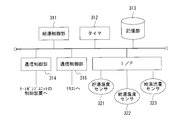
- FIG. 2 shows a functional block diagram of the control device 310 of the tank unit 300.
- the control device 310 includes a hot water supply control unit 311, a timer 312, a storage unit 313 that stores various setting information, error information, control programs, and the like, and communication that controls communication with the heat pump unit 200.
- a control unit 314, a communication control unit 315 that controls communication with the remote controllers 100 and 100 ′, and an interface 316 for connecting controlled devices such as each pump of the tank unit 300 and various sensors are provided.
- a hot water storage temperature sensor 321 that detects the temperature of hot water stored in a hot water storage tank
- a hot water supply temperature sensor 322 that detects the temperature of hot water supplied to the kitchen faucet or shower
- a kitchen faucet or shower are used as sensors.
- the hot water supply flow rate sensor 323 which detects the flow volume of the hot water supplied is illustrated.
- the hot water supply control unit 311 executes a control program stored in the storage unit 313, thereby performing a control process based on the detection result of each sensor and the setting information stored in the storage unit.
- the hot water supply control unit 311 also monitors the detection results and self-diagnosis functions of each sensor, and detects the presence or absence of various errors. The process at the time of error detection will be described later.
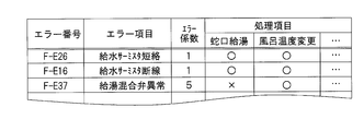
- the error information includes an error number, an error item (cause), and processing item information that can be executed when an error occurs.
- This processing item means various control operations by the control device 310.
- the processing item is not only a single function such as a hot water supply operation from a faucet, but also a plurality of devices such as a “boiling operation”. It also includes operations consisting of control over time.
- the error information stored in the storage unit 313 is binary information (represented as “ ⁇ ” and “x” in FIG. 3) regarding whether or not the processing item can be executed when an error occurs for various processing items. keeping.
- FIGS. 4 is a front view of the remote controller
- FIG. 5 is a functional block diagram of the remote controller. Since the bathroom remote controller 100 and the kitchen remote controller 100 'have the same configuration, only the bathroom remote controller 100 will be described here.
- the remote controller 100 includes a display unit 110 such as a liquid crystal display, an organic EL display, or a fluorescent display tube disposed in the center of the front surface of the rectangular casing 101.
- the remote controller 100 includes a hot water temperature up button 111 for increasing the hot water temperature, a hot water temperature down button 112 for decreasing the hot water temperature, and a priority button 113 for the remote controller 100 of the remote controller 100 to obtain priority.
- a menu button 121 for mainly inputting an instruction to switch from the normal display mode to the setting change mode, and a setting item movement instruction and a setting value change instruction in the setting change mode.
- An up button 122 and a down button 123 for input, and a determination button 124 for inputting a setting item name and setting value confirmation instruction are provided.
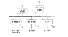
- Fig. 5 shows a functional block diagram of the remote control.
- the remote control 100 includes a remote control unit 131, a storage unit 132 that stores a list of setting item names, a control program, and the like, and a communication control unit that controls communication with the control device 310 of the tank unit 300. 133, a display control unit 134 that performs display control of the display unit 110, and an interface 135 with each button.
- the remote controller control unit 131 operates according to the control program stored in the storage unit 132.
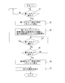
- step S1 the hot water supply control unit 311 of the control device 310 detects the occurrence of the first error by various sensors, a self-diagnosis function, or the like.
- the error information about the error is acquired from the storage unit 313, and an error number or necessary Accordingly, the error item is displayed on the display unit 110 of the remote controllers 100 and 100 ′ (step S2).
- the hot water supply control unit 311 performs each processing item based on the information on whether or not each processing item is included in the error information (step S3). That is, the operation is continued in a state where implementation of some functions is restricted.
- step S4 the process to step S1 (step S4).
- the hot water supply control unit 311 detects the occurrence of the second error during the occurrence of the first error (steps S4 and S5), the remote control 100, 100 ′ displays a display indicating that a fatal error has occurred. It is displayed on the display unit 110 (step S6). Thereafter, the hot water supply control unit 311 stops all operations related to the control of the hot water supply device (step S7).
- the operation stop here relates to each processing item included in the error information stored in the storage unit 313. In other words, the hot water supply control unit 311 performs hot water supply control assuming that all the processing items cannot be performed. Moreover, the hot water supply control unit 311 continues the display process in the remote controllers 100 and 100 'in step S6.
- the heat pump hot water supply apparatus even if one error occurs, it continues to operate on the processing items that can be performed with the first error unless another error occurs. Can do. Thereby, driving efficiency and convenience are improved. In addition, when a plurality of errors occur, even if there are processing items that can be performed independently for each error, the operation stops in the entire hot water supply apparatus, so that safety is high.
- a heat pump hot water supply apparatus according to a second embodiment of the present invention will be described with reference to the drawings.
- the heat pump type hot water supply apparatus according to the present embodiment is different from the first embodiment in the condition for stopping all operations of the hot water supply apparatus.
- a condition is that a plurality of errors occur simultaneously.
- each error is divided into several categories according to its properties and the condition is that errors related to a plurality of categories occur simultaneously.
- the differences will be described in detail.
- FIG. 7 shows an example of error information stored in the storage unit 313. As shown in FIG. 7, in this embodiment, a classification code is assigned to each error.
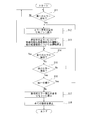
- step S11 When the hot water supply control unit 311 of the control device 310 detects the occurrence of the first error by various sensors, a self-diagnosis function, or the like (step S11), the error information about the error is acquired from the storage unit 313, and an error number or necessary Accordingly, the error item is displayed on the display unit 110 of the remote controllers 100 and 100 ′ (step S12). Thereafter, the hot water supply control unit 311 performs each processing item based on the information on whether or not each processing item is included in the error information of the error that is occurring (step S13). That is, the operation is continued in a state where implementation of some functions is restricted. When the hot water supply control unit 311 detects recovery of the error that is occurring, the hot water supply control unit 311 moves the process to step S11 (step S14).
- the hot water supply control unit 311 detects the occurrence of another error during the occurrence of the error (steps S14 and S15), the error information of the error is acquired from the storage unit 313, and the classification code included in the error information and Then, it is determined whether or not the classification codes included in the error information of the error that has already occurred match (step S16).
- the hot water supply control unit 311 displays an error number or an error item as necessary on the display unit 110 of the remote control 100 or 100 'for the newly generated error (step S12). Thereafter, the hot water supply control unit 311 executes each processing item based on the information on whether or not each processing item is included in the error information of all the errors that are occurring (step S13). Note that, when there is a contradiction in whether or not the processing item can be executed due to a plurality of errors, priority is given to the inability to execute the operation for safety.
- the hot water supply control unit 311 displays a display indicating that a fatal error has occurred on the display unit 110 of the remote control 100 or 100 '(step S17). Thereafter, the hot water supply control unit 311 stops all operations related to the control of the hot water supply device (step S18).
- the operation stop here relates to each processing item included in the error information stored in the storage unit 313. In other words, the hot water supply control unit 311 performs hot water supply control assuming that all the processing items cannot be performed. Further, the hot water supply control unit 311 continues the display process in the remote controllers 100 and 100 'in the step S17.
- a heat pump type hot water supply apparatus according to a third embodiment of the present invention will be described with reference to the drawings.
- the heat pump type hot water supply apparatus according to the present embodiment is different from the first embodiment in the condition for stopping all operations of the hot water supply apparatus.
- a condition is that a plurality of errors occur simultaneously.
- an error coefficient is assigned to each error according to its property or the like, and the condition is that the sum of error coefficients of the error that is occurring exceeds a predetermined threshold.
- FIG. 9 shows an example of error information stored in the storage unit 313. As shown in FIG. 9, in this embodiment, an error coefficient is given for each error.
- step S21 the operation of the controller 310 of the tank unit 300 when an error occurs will be described with reference to the flowchart of FIG.
- step S21 the error information about the error is acquired from the storage unit 313, and an error number or necessary Accordingly, the error item is displayed on the display unit 110 of the remote controllers 100 and 100 '(step S22).
- step S23 the hot water supply control unit 311 performs each processing item based on the information on the availability of each processing item included in the error information of the error that is occurring (step S23). That is, the operation is continued in a state where implementation of some functions is restricted.
- step S24 the hot water supply control unit 311 moves the process to step S11 (step S24).
- the hot water supply control unit 311 detects the occurrence of another error during the occurrence of the error (steps S24 and S25), the error information of the error is acquired from the storage unit 313, and the error coefficient included in the error information and Then, the sum with the error coefficient included in the error information of the error that has already occurred is calculated (step S26). Next, the hot water supply control unit 311 determines whether or not the calculated sum of error coefficients exceeds a predetermined threshold (step S27). When the threshold value is not exceeded, the hot water supply control unit 311 displays an error number or an error item as necessary on the display unit 110 of the remote control 100 or 100 'for a newly generated error (step S22).
- the hot water supply control unit 311 performs each processing item based on the information on whether or not each processing item is included in the error information of all the errors that are occurring (step S23). Note that, when there is a contradiction in whether or not the processing item can be executed due to a plurality of errors, priority is given to the inability to execute the operation for safety.
- the hot water supply control unit 311 displays a display indicating that a fatal error has occurred on the display unit 110 of the remote control 100 or 100 '(step S28). Thereafter, the hot water supply control unit 311 stops all operations related to the control of the hot water supply device (step S29).
- the operation stop here relates to each processing item included in the error information stored in the storage unit 313. In other words, the hot water supply control unit 311 performs hot water supply control assuming that all the processing items cannot be performed. Further, the hot water supply control unit 311 continues the display process in the remote controllers 100 and 100 'in step S28.
- the heat pump type hot water supply apparatus According to the heat pump type hot water supply apparatus according to the present embodiment, even if a plurality of errors occur, it is not possible to carry out with each error that has occurred unless the sum of error coefficients of each error exceeds a predetermined threshold.
- the operation is stopped only for possible processing items, and other processing items can be continuously operated. Thereby, driving efficiency and convenience are improved.
- Other operations and effects are the same as those in the first embodiment.
- the present invention is not limited to this.
- the case where the two remote controllers 100 and 100 'are installed in the bathroom and kitchen has been described.
- the number of remote controllers may be one or three or more.
- the tank unit 300 and the heat pump unit 200 are configured as separate housings so that they can be installed in different locations. However, they may be installed in the same location.
- the tank unit 300 and the heat pump unit 200 may be configured as separate casings, and both may be stacked vertically and installed side by side. Further, the tank unit 300 and the heat pump unit 200 may be configured in a common housing.
Landscapes
- Engineering & Computer Science (AREA)
- Physics & Mathematics (AREA)
- Thermal Sciences (AREA)
- Chemical & Material Sciences (AREA)
- Combustion & Propulsion (AREA)
- Mechanical Engineering (AREA)
- General Engineering & Computer Science (AREA)
- Heat-Pump Type And Storage Water Heaters (AREA)
- Control For Baths (AREA)
Abstract
給湯器及び給湯制御装置310を有するタンクユニット300と、熱交換器を有するヒートポンプユニット200と、リモコン100を備えたヒートポンプ式給湯装置において、給湯制御装置310は、エラー検出手段が第1のエラーを検出すると記憶部313に記憶されている第1のエラーに対応する処理項目情報に基づき実施可能な処理を継続するとともに、第1のエラーの発生中にエラー検出手段が第2のエラーを検出すると全ての処理項目が実施不可能として給湯器を制御する。
Description
本発明は、ヒートポンプを熱源とした給湯装置に関する。
この種のヒートポンプ式給湯装置は、例えば特許文献1に記載されているように、熱交換器等を有するヒートポンプユニットと、貯湯タンクや給水ポンプ等を備えたタンクユニットとを備え、ヒートポンプユニットで得た熱を用いてタンクユニット内で水を加熱・貯湯し、必要時に給湯する。タンクユニットに設けられた制御装置には動作状況の表示や動作設定の入力を行うリモコンが接続されている。リモコンには液晶ディスプレイなどの表示部及び各種ボタンからなる入力部が設けられており、給湯温度などの各種設定が可能となっている。タンクユニットの制御装置はリモコンにより設定された各種設定値にしたがって温度制御や流量制御を行う。
また、この種のヒートポンプ式給湯装置では、各種のエラー発生の有無を監視し、エラー発生を検出すると給湯装置全体の運転を停止させるとともに、リモコンにエラー発生の旨を表示させる。そして、機器の修理等によりエラーから復旧した時点で運転再開が可能となる。
特開2007-192499号公報
従来のヒートポンプ式給湯装置では、エラーが1つでも発生すると給湯装置全体の運転が停止してしまう。しかし、エラーには様々な種類のものがあり、発生したエラーによっては装置全体或いは装置の一部機能の運転に支障がないものも多数存在する。そして、従来のヒートポンプ式給湯装置では、このような軽微なエラーの場合にも致命的なエラーと同様に給湯装置全体が停止してしまうので、運転効率の向上に限界があるとともに利便性が悪いという問題があった。
本発明は、上記事情に鑑みてなされたものであり、その目的とするところは、運転効率及び利便性の高いヒートポンプ式給湯装置を提供することにある。
上記目的を達成するために、本発明は、熱交換器と、前記熱交換器で加熱された水を供給する給湯器と、給湯器を制御する給湯制御装置と、給湯制御装置と接続して動作状況の表示や動作設定の入力を行うリモコンとを備えたヒートポンプ式給湯装置において、エラーを検出するエラー検出手段と、エラー検出手段により検出される各エラーに対して該エラーの発生中に実施可能な処理項目の情報を記憶した記憶手段とを備える。前記給湯制御装置は、エラー検出手段が第1のエラーを検出すると前記記憶手段に記憶されている第1のエラーに対応する処理項目情報に基づき実施可能な処理を継続するとともに、第1のエラーの発生中にエラー検出手段が第2のエラーを検出すると全ての処理項目が実施不可能であるとして給湯器を制御する。
本発明によれば、第1のエラーが発生した場合、該第1のエラー発生中でも実施可能な処理項目についてはエラーが解消されなくても継続して実施することができるので運転効率及び利便性が向上する。なお、本発明では、第1のエラー発生中に第2のエラーが発生すると全ての処理項目が実施不可能となるので安全性は担保されている。
本発明の好適な態様の一例としては、前記給湯制御装置が、エラー検出手段が第1のエラーを検出すると該第1のエラーに係る情報をリモコンに表示させるとともに、第1のエラーの発生中にエラー検出手段が第2のエラーを検出すると所定のメッセージをリモコンに表示させるものが挙げられる。
また、本発明の好適な態様の他の例としては、前記記憶手段に記憶した処理項目情報はエラー分類を含み、前記給湯制御装置は、エラー検出手段が第1のエラーを検出すると前記記憶手段に記憶されている第1のエラーに対応する処理項目情報に基づき実施可能な処理を継続するとともに、第1のエラーの発生中にエラー検出手段が第1のエラーとは異なるエラー分類に係る第2のエラーを検出すると全ての処理項目が実施不可能であるとして給湯器を制御することを特徴とするものが挙げられる。本発明によれば、エラーが複数発生した場合であっても各エラーが同一の分類に含まれる場合には実施可能な処理が継続されるので、運転効率及び利便性が向上する。
また、本発明の好適な態様の他の例としては、前記記憶手段に記憶した処理項目情報はエラー係数を含み、前記給湯制御装置は、エラー検出手段が第1のエラーを検出すると前記記憶手段に記憶されている第1のエラーに対応する処理項目情報に基づき実施可能な処理を継続するとともに、第1のエラーの発生中にエラー検出手段が第2のエラーを検出すると第1のエラーのエラー係数及び第2のエラーのエラー係数の和を算出し、エラー係数の和が所定の閾値を超えた場合に全ての処理項目が実施不可能であるとして給湯器を制御することを特徴とするものが挙げられる。本発明によれば、安全度等を考慮して各エラーについてエラー係数を付することにより、エラーが複数発生した場合であってもエラー係数の和が所定の閾値を超えない場合には実施可能な処理が継続されるので、運転効率及び利便性が向上する。
以上説明したように本発明によれば、第1のエラーが発生した場合、該第1のエラー発生中でも実施可能な処理項目については当該エラーが解消されなくても継続して実施することができるので運転効率及び利便性が向上する。
100,100’…リモコン、110…表示部、200…ヒートポンプユニット、250…管路、251…ケーブル、300…タンクユニット、310…制御装置、311…給湯制御部、312…タイマ、313…記憶部、314,315…通信制御部。
(第1の実施の形態)
本発明の第1の実施の形態に係るヒートポンプ式給湯装置について図面を参照して説明する。図1はヒートポンプ式給湯装置の概略図である。
本発明の第1の実施の形態に係るヒートポンプ式給湯装置について図面を参照して説明する。図1はヒートポンプ式給湯装置の概略図である。
ヒートポンプ式給湯装置は、図1に示すように、室外やボイラー室などの室内に設置され熱交換器を有するヒートポンプユニット200と、貯湯タンクや給湯ポンプを備え前記ヒートポンプユニット200で得られた熱を用いて水を加熱・給湯するタンクユニット300と、タンクユニット300に設けられた制御装置310と接続した複数(本実施の形態では2つ)のリモコン100,100’とを備えている。本実施の形態に係るタンクユニット300は、浴室の風呂桶の水を循環させて加熱・保温させるとともに、浴室のシャワー及び台所の蛇口にお湯を供給する。一方のリモコン100は浴室に設置され、他方のリモコン100’は台所に設置される。なお、ヒートポンプユニット200とタンクユニット300との間には、熱交換用の水を循環させる管路250と、制御信号や電源を伝送するケーブル251とが設けられている。
図2にタンクユニット300の制御装置310の機能ブロック図を示す。図2に示すように、制御装置310は、給湯制御部311と、タイマ312と、各種設定情報・エラー情報・制御プログラムなどを記憶する記憶部313と、ヒートポンプユニット200との通信を制御する通信制御部314と、リモコン100,100’との通信を制御する通信制御部315と、タンクユニット300の各ポンプなどの被制御装置や各種センサを接続するためのインタフェイス316とを備えている。図2ではセンサ類として、貯湯タンクに貯えられたお湯の温度を検出する貯湯温度センサ321と、台所蛇口やシャワーに供給されるお湯の温度を検出する給湯温度センサ322と、台所蛇口やシャワーに供給されるお湯の流量を検出する給湯流量センサ323を例示している。給湯制御部311は、記憶部313に記憶されている制御プログラムを実行することにより、各センサによる検出結果や記憶部に記憶されている設定情報に基づき制御処理を行う。また、給湯制御部311は、各センサによる検出結果や自己診断機能を監視し、各種のエラー発生の有無を検出する。エラー検出時の処理については後述する。
記憶部313に記憶されているエラー情報の一例を図3に示す。図3に示すようにエラー情報は、エラー番号、エラー項目(原因)、エラー発生時に実施可能な処理項目情報を含む。この処理項目とは、制御装置310による各種制御動作を意味し、例えば蛇口からの給湯動作などの単一の機能からなる動作だけでなく、例えば「沸き増し運転」などのように複数の機器の経時的な制御からなる動作も含む。記憶部313に記憶されているエラー情報は、種々の処理項目について、エラー発生時に当該処理項目を実施できるか否かの二値情報(図3では「○」と「×」として表記した)を保持している。
次に、リモコンについて図4及び図5を参照して説明する。図4はリモコンの正面図、図5はリモコンの機能ブロック図である。なお、浴室用のリモコン100と台所用のリモコン100’とは同様の構成なのでここでは浴室用のリモコン100についてのみ説明する。
リモコン100は、図4に示すように、矩形の筐体101の前面中央部に配置された液晶ディスプレイ、有機ELディスプレイや蛍光表示管などの表示部110を備えている。また、リモコン100は、給湯温度を上げるための給湯温度アップボタン111と、給湯温度を下げるための給湯温度ダウンボタン112と、自身のリモコン100が優先権を獲得するための優先権ボタン113とを備えている。さらに、その他の設定情報の変更等を行うために、主として通常表示モードから設定変更モードへの切替え指示を入力するメニューボタン121と、設定変更モードにおいて設定項目の移動指示や設定値の変更指示を入力するアップボタン122及びダウンボタン123、設定項目名や設定値の確定指示を入力する決定ボタン124とを備えている。
図5にリモコンの機能ブロック図を示す。リモコン100は、図5に示すように、リモコン制御部131と、設定項目名のリストや制御プログラムなどを記憶する記憶部132と、タンクユニット300の制御装置310との通信を制御する通信制御部133と、表示部110の表示制御を行う表示制御部134と、各ボタンとのインタフェイス135とを備えている。リモコン制御部131は、記憶部132に記憶されている制御プログラムにしたがって動作する。
次に、エラー発生時におけるタンクユニット300の制御装置310の動作について図6のフローチャートを参照して説明する。制御装置310の給湯制御部311は、各種センサや自己診断機能等により第1のエラーの発生を検出すると(ステップS1)、当該エラーについてのエラー情報を記憶部313から取得し、エラー番号や必要に応じてエラー項目をリモコン100,100’の表示部110に表示させる(ステップS2)。以降、給湯制御部311は、エラー情報に含まれる各処理項目毎の実施可否の情報に基づき、各処理項目を実施する(ステップS3)。すなわち、一部機能の実施を制限した状態で運転を継続させる。給湯制御部311は、前記第1のエラーの復旧を検出すると処理を前記ステップS1に移す(ステップS4)。
一方、給湯制御部311は、前記第1のエラーの発生中に第2のエラーの発生を検出すると(ステップS4,S5)、致命的なエラーが発生した旨を表示をリモコン100,100’の表示部110に表示させる(ステップS6)。以降、給湯制御部311は、給湯装置の制御に関して全ての動作を停止させる(ステップS7)。なお、ここでの動作停止は、記憶部313に記憶されているエラー情報に含まれる各処理項目に関するものである。換言すれば、給湯制御部311は、全ての処理項目が実施不可能であるとして給湯制御を行う。また、給湯制御部311は、前記ステップS6におけるリモコン100,100’における表示処理は継続させる。
本実施の形態に係るヒートポンプ式給湯装置によれば、1つのエラーが発生した場合であっても、さらに他のエラーが発生しない限り、最初のエラーで実施可能な処理項目については継続して動作することできる。これにより運転効率及び利便性が向上したものとなる。また、複数のエラーが発生すると、各エラーに対して単独では実施可能な処理項目がある場合であっても、給湯装置全体で動作が停止するので安全性が高いものとなる。
(第2の実施の形態)
本発明の第2の実施の形態に係るヒートポンプ式給湯装置について図面を参照して説明する。本実施の形態に係るヒートポンプ式給湯装置が第1の実施の形態と異なる点は、給湯装置の動作を全て停止するための条件にある。具体的には、第1の実施の形態では複数のエラーが同時に発生する事が条件であった。一方、本実施の形態では、各エラーをその性質等に応じて幾つかの分類に分け、複数の分類に係るエラーが同時に発生することを条件とする。以下、相違点について詳述する。
本発明の第2の実施の形態に係るヒートポンプ式給湯装置について図面を参照して説明する。本実施の形態に係るヒートポンプ式給湯装置が第1の実施の形態と異なる点は、給湯装置の動作を全て停止するための条件にある。具体的には、第1の実施の形態では複数のエラーが同時に発生する事が条件であった。一方、本実施の形態では、各エラーをその性質等に応じて幾つかの分類に分け、複数の分類に係るエラーが同時に発生することを条件とする。以下、相違点について詳述する。
図7に記憶部313に記憶されているエラー情報の一例を示す。図7に示すように、本実施の形態では、各エラーについて分類コードが付与されている。
次に、エラー発生時におけるタンクユニット300の制御装置310の動作について図8のフローチャートを参照して説明する。制御装置310の給湯制御部311は、各種センサや自己診断機能等により第1のエラーの発生を検出すると(ステップS11)、当該エラーについてのエラー情報を記憶部313から取得し、エラー番号や必要に応じてエラー項目をリモコン100,100’の表示部110に表示させる(ステップS12)。以降、給湯制御部311は、発生中のエラーのエラー情報に含まれる各処理項目毎の実施可否の情報に基づき、各処理項目を実施する(ステップS13)。すなわち、一部機能の実施を制限した状態で運転を継続させる。給湯制御部311は、発生中のエラーの復旧を検出すると処理を前記ステップS11に移す(ステップS14)。
一方、給湯制御部311は、エラーの発生中に他のエラーの発生を検出すると(ステップS14,S15)、該エラーのエラー情報を記憶部313から取得し、該エラー情報に含まれる分類コードと、既に発生中のエラーのエラー情報に含まれる分類コードが一致するかを判定する(ステップS16)。給湯制御部311は、両者が一致する場合には、新たに発生したエラーについて、エラー番号や必要に応じてエラー項目をリモコン100,100’の表示部110に表示させる(ステップS12)。以降、給湯制御部311は、発生中の全てのエラーのエラー情報に含まれる各処理項目毎の実施可否の情報に基づき、各処理項目を実施する(ステップS13)。なお、複数のエラーで処理項目の実施可否が矛盾する際には、動作の安全のため実施不可を優先させる。
一方、分類コードが一致しない場合、給湯制御部311は、致命的なエラーが発生した旨を表示をリモコン100,100’の表示部110に表示させる(ステップS17)。以降、給湯制御部311は、給湯装置の制御に関して全ての動作を停止させる(ステップS18)。なお、ここでの動作停止は、記憶部313に記憶されているエラー情報に含まれる各処理項目に関するものである。換言すれば、給湯制御部311は、全ての処理項目が実施不可能であるとして給湯制御を行う。また、給湯制御部311は、前記ステップS17におけるリモコン100,100’における表示処理は継続させる。
本実施の形態に係るヒートポンプ式給湯装置によれば、複数のエラーが発生した場合であっても、各エラーの分類が1種類のみである限り、発生中の各エラーで実施不可能な処理項目についてのみ動作が停止し、他の処理項目については継続して動作することできる。これにより運転効率及び利便性が向上したものとなる。他の作用・効果は第1の実施の形態と同様である。
(第3の実施の形態)
本発明の第3の実施の形態に係るヒートポンプ式給湯装置について図面を参照して説明する。本実施の形態に係るヒートポンプ式給湯装置が第1の実施の形態と異なる点は、給湯装置の動作を全て停止するための条件にある。具体的には、第1の実施の形態では複数のエラーが同時に発生する事が条件であった。一方、本実施の形態では、各エラーに対してその性質等に応じてエラー係数を付与し、発生中のエラーのエラー係数の和が所定の閾値を超えることを条件とする。以下、相違点について詳述する。
本発明の第3の実施の形態に係るヒートポンプ式給湯装置について図面を参照して説明する。本実施の形態に係るヒートポンプ式給湯装置が第1の実施の形態と異なる点は、給湯装置の動作を全て停止するための条件にある。具体的には、第1の実施の形態では複数のエラーが同時に発生する事が条件であった。一方、本実施の形態では、各エラーに対してその性質等に応じてエラー係数を付与し、発生中のエラーのエラー係数の和が所定の閾値を超えることを条件とする。以下、相違点について詳述する。
図9に記憶部313に記憶されているエラー情報の一例を示す。図9に示すように、本実施の形態では、各エラーについてエラー係数が付与されている。
次に、エラー発生時におけるタンクユニット300の制御装置310の動作について図10のフローチャートを参照して説明する。制御装置310の給湯制御部311は、各種センサや自己診断機能等により第1のエラーの発生を検出すると(ステップS21)、当該エラーについてのエラー情報を記憶部313から取得し、エラー番号や必要に応じてエラー項目をリモコン100,100’の表示部110に表示させる(ステップS22)。以降、給湯制御部311は、発生中のエラーのエラー情報に含まれる各処理項目毎の実施可否の情報に基づき、各処理項目を実施する(ステップS23)。すなわち、一部機能の実施を制限した状態で運転を継続させる。給湯制御部311は、発生中のエラーの復旧を検出すると処理を前記ステップS11に移す(ステップS24)。
一方、給湯制御部311は、エラーの発生中に他のエラーの発生を検出すると(ステップS24,S25)、該エラーのエラー情報を記憶部313から取得し、該エラー情報に含まれるエラー係数と、既に発生中のエラーのエラー情報に含まれるエラー係数との和を算出する(ステップS26)。次に、給湯制御部311は、算出したエラー係数の和が所定の閾値を超えているか否かを判定する(ステップS27)。給湯制御部311は、閾値を超えていない場合には、新たに発生したエラーについて、エラー番号や必要に応じてエラー項目をリモコン100,100’の表示部110に表示させる(ステップS22)。以降、給湯制御部311は、発生中の全てのエラーのエラー情報に含まれる各処理項目毎の実施可否の情報に基づき、各処理項目を実施する(ステップS23)。なお、複数のエラーで処理項目の実施可否が矛盾する際には、動作の安全のため実施不可を優先させる。
一方、エラー係数の和が所定の閾値を超えた場合、給湯制御部311は、致命的なエラーが発生した旨を表示をリモコン100,100’の表示部110に表示させる(ステップS28)。以降、給湯制御部311は、給湯装置の制御に関して全ての動作を停止させる(ステップS29)。なお、ここでの動作停止は、記憶部313に記憶されているエラー情報に含まれる各処理項目に関するものである。換言すれば、給湯制御部311は、全ての処理項目が実施不可能であるとして給湯制御を行う。また、給湯制御部311は、前記ステップS28におけるリモコン100,100’における表示処理は継続させる。
本実施の形態に係るヒートポンプ式給湯装置によれば、複数のエラーが発生した場合であっても、各エラーのエラー係数の和が所定の閾値を超えない限り、発生中の各エラーで実施不可能な処理項目についてのみ動作が停止し、他の処理項目については継続して動作することできる。これにより運転効率及び利便性が向上したものとなる。他の作用・効果は第1の実施の形態と同様である。
以上本発明の一実施の形態について詳述したが本発明はこれに限定されるものではない。例えば、上記実施の形態では、浴室及び台所に設置した2つのリモコン100,100’を有する場合について説明したが、リモコンの数は1つであっても3つ以上であってもよい。
また、本実施の形態では、タンクユニット300とヒートポンプユニット200を別筐体として構成することにより両者をそれぞれ別の場所に設置可能としたが、両者を同じ場所に設置するようにしても良い。この場合、上記実施形態と同様に、タンクユニット300とヒートポンプユニット200とを別筐体として構成するとともに両者を縦に積み重ねて設置したり、横に並べて設置してもよい。また、タンクユニット300とヒートポンプユニット200とを共通の筐体内に構成するようにしてもよい。
Claims (4)
- 熱交換器と、前記熱交換器で加熱された水を供給する給湯器と、給湯器を制御する給湯制御装置と、給湯制御装置と接続して動作状況の表示や動作設定の入力を行うリモコンとを備えたヒートポンプ式給湯装置において、
エラーを検出するエラー検出手段と、
エラー検出手段により検出される各エラーに対して該エラーの発生中に実施可能な処理項目の情報を記憶した記憶手段とを備え、
前記給湯制御装置は、エラー検出手段が第1のエラーを検出すると前記記憶手段に記憶されている第1のエラーに対応する処理項目情報に基づき実施可能な処理を継続するとともに、第1のエラーの発生中にエラー検出手段が第2のエラーを検出すると全ての処理項目が実施不可能であるとして給湯器を制御する
ことを特徴とするヒートポンプ式給湯装置。 - 前記給湯制御装置は、エラー検出手段が第1のエラーを検出すると該第1のエラーに係る情報をリモコンに表示させるとともに、第1のエラーの発生中にエラー検出手段が第2のエラーを検出すると所定のメッセージをリモコンに表示させる
ことを特徴とする請求項1記載のヒートポンプ式給湯装置。 - 前記記憶手段に記憶した処理項目情報はエラー分類を含み、
前記給湯制御装置は、エラー検出手段が第1のエラーを検出すると前記記憶手段に記憶されている第1のエラーに対応する処理項目情報に基づき実施可能な処理を継続するとともに、第1のエラーの発生中にエラー検出手段が第1のエラーとは異なるエラー分類に係る第2のエラーを検出すると全ての処理項目が実施不可能であるとして給湯器を制御する
ことを特徴とする請求項1記載のヒートポンプ式給湯装置。 - 前記記憶手段に記憶した処理項目情報はエラー係数を含み、
前記給湯制御装置は、エラー検出手段が第1のエラーを検出すると前記記憶手段に記憶されている第1のエラーに対応する処理項目情報に基づき実施可能な処理を継続するとともに、第1のエラーの発生中にエラー検出手段が第2のエラーを検出すると第1のエラーのエラー係数及び第2のエラーのエラー係数の和を算出し、エラー係数の和が所定の閾値を超えた場合に全ての処理項目が実施不可能であるとして給湯器を制御する
ことを特徴とする請求項1記載のヒートポンプ式給湯装置。
Applications Claiming Priority (2)
| Application Number | Priority Date | Filing Date | Title |
|---|---|---|---|
| JP2008121198A JP5209369B2 (ja) | 2008-05-07 | 2008-05-07 | ヒートポンプ式給湯装置 |
| JP2008-121198 | 2008-05-07 |
Publications (1)
| Publication Number | Publication Date |
|---|---|
| WO2009136453A1 true WO2009136453A1 (ja) | 2009-11-12 |
Family
ID=41264510
Family Applications (1)
| Application Number | Title | Priority Date | Filing Date |
|---|---|---|---|
| PCT/JP2008/063966 Ceased WO2009136453A1 (ja) | 2008-05-07 | 2008-08-04 | ヒートポンプ式給湯装置 |
Country Status (2)
| Country | Link |
|---|---|
| JP (1) | JP5209369B2 (ja) |
| WO (1) | WO2009136453A1 (ja) |
Citations (2)
| Publication number | Priority date | Publication date | Assignee | Title |
|---|---|---|---|---|
| JPH07120063A (ja) * | 1993-10-29 | 1995-05-12 | Kyushu Henatsuki Kk | 貯湯式電気温水器 |
| JP2003222393A (ja) * | 2002-01-29 | 2003-08-08 | Daikin Ind Ltd | 給湯装置 |
-
2008
- 2008-05-07 JP JP2008121198A patent/JP5209369B2/ja not_active Expired - Fee Related
- 2008-08-04 WO PCT/JP2008/063966 patent/WO2009136453A1/ja not_active Ceased
Patent Citations (2)
| Publication number | Priority date | Publication date | Assignee | Title |
|---|---|---|---|---|
| JPH07120063A (ja) * | 1993-10-29 | 1995-05-12 | Kyushu Henatsuki Kk | 貯湯式電気温水器 |
| JP2003222393A (ja) * | 2002-01-29 | 2003-08-08 | Daikin Ind Ltd | 給湯装置 |
Also Published As
| Publication number | Publication date |
|---|---|
| JP2009270760A (ja) | 2009-11-19 |
| JP5209369B2 (ja) | 2013-06-12 |
Similar Documents
| Publication | Publication Date | Title |
|---|---|---|
| JP6625239B2 (ja) | 空気調和機および空気調和システム | |
| JP2008232562A (ja) | 空調システム | |
| US10742439B2 (en) | Communication adapter | |
| JP2017136566A (ja) | 給水装置 | |
| KR101459278B1 (ko) | 보일러의 삼방변 고착 및 오동작 검출방법 | |
| JP2021135610A (ja) | 温水利用設備および温水利用設備の遠隔制御システム | |
| JP5209369B2 (ja) | ヒートポンプ式給湯装置 | |
| JP7082915B2 (ja) | ガス供給制御装置、ガス供給制御プログラム | |
| JP2018053789A (ja) | 給水装置 | |
| JP4973934B2 (ja) | 連結給湯システム | |
| JP2013242091A (ja) | 貯湯式給湯機 | |
| JP6201939B2 (ja) | 給湯機 | |
| JP3856043B1 (ja) | 給湯装置 | |
| JP4375204B2 (ja) | 貯湯式温水器 | |
| JP5997922B2 (ja) | 給湯機 | |
| KR100551194B1 (ko) | 보일러의 정전보상 이상감지 제어시스템 | |
| JP2017198431A (ja) | 給湯システム及びこれを備えた電力制限システム | |
| JP6322566B2 (ja) | 異常表示システム | |
| JP2001349607A (ja) | 給湯装置のデータ補完方法及び給湯装置 | |
| JP2007255761A (ja) | 給湯器のリモコン装置 | |
| JP2002147850A (ja) | 給湯器の状態記憶装置 | |
| JP2007040552A (ja) | 給湯機システムとそのプログラム | |
| JP4487858B2 (ja) | 給湯装置用リモコン | |
| KR101787673B1 (ko) | 보일러 조절장치의 버튼 오조작 또는 고장시 제어방법 | |
| JP2010255922A (ja) | 温水器の制御装置および方法 |
Legal Events
| Date | Code | Title | Description |
|---|---|---|---|
| 121 | Ep: the epo has been informed by wipo that ep was designated in this application |
Ref document number: 08808667 Country of ref document: EP Kind code of ref document: A1 |
|
| NENP | Non-entry into the national phase |
Ref country code: DE |
|
| 122 | Ep: pct application non-entry in european phase |
Ref document number: 08808667 Country of ref document: EP Kind code of ref document: A1 |