WO2009132543A1 - 为用户分配应答信道的方法、装置和系统 - Google Patents
为用户分配应答信道的方法、装置和系统 Download PDFInfo
- Publication number
- WO2009132543A1 WO2009132543A1 PCT/CN2009/071124 CN2009071124W WO2009132543A1 WO 2009132543 A1 WO2009132543 A1 WO 2009132543A1 CN 2009071124 W CN2009071124 W CN 2009071124W WO 2009132543 A1 WO2009132543 A1 WO 2009132543A1
- Authority
- WO
- WIPO (PCT)
- Prior art keywords
- cce
- sub
- label
- subframe
- blocks
- Prior art date
Links
Classifications
-
- H—ELECTRICITY
- H04—ELECTRIC COMMUNICATION TECHNIQUE
- H04L—TRANSMISSION OF DIGITAL INFORMATION, e.g. TELEGRAPHIC COMMUNICATION
- H04L1/00—Arrangements for detecting or preventing errors in the information received
- H04L1/12—Arrangements for detecting or preventing errors in the information received by using return channel
- H04L1/16—Arrangements for detecting or preventing errors in the information received by using return channel in which the return channel carries supervisory signals, e.g. repetition request signals
- H04L1/1607—Details of the supervisory signal
-
- H—ELECTRICITY
- H04—ELECTRIC COMMUNICATION TECHNIQUE
- H04L—TRANSMISSION OF DIGITAL INFORMATION, e.g. TELEGRAPHIC COMMUNICATION
- H04L1/00—Arrangements for detecting or preventing errors in the information received
- H04L1/12—Arrangements for detecting or preventing errors in the information received by using return channel
- H04L1/16—Arrangements for detecting or preventing errors in the information received by using return channel in which the return channel carries supervisory signals, e.g. repetition request signals
- H04L1/18—Automatic repetition systems, e.g. Van Duuren systems
- H04L1/1829—Arrangements specially adapted for the receiver end
- H04L1/1854—Scheduling and prioritising arrangements
-
- H—ELECTRICITY
- H04—ELECTRIC COMMUNICATION TECHNIQUE
- H04L—TRANSMISSION OF DIGITAL INFORMATION, e.g. TELEGRAPHIC COMMUNICATION
- H04L1/00—Arrangements for detecting or preventing errors in the information received
- H04L1/12—Arrangements for detecting or preventing errors in the information received by using return channel
- H04L1/16—Arrangements for detecting or preventing errors in the information received by using return channel in which the return channel carries supervisory signals, e.g. repetition request signals
- H04L1/18—Automatic repetition systems, e.g. Van Duuren systems
- H04L1/1829—Arrangements specially adapted for the receiver end
- H04L1/1861—Physical mapping arrangements
-
- H—ELECTRICITY
- H04—ELECTRIC COMMUNICATION TECHNIQUE
- H04L—TRANSMISSION OF DIGITAL INFORMATION, e.g. TELEGRAPHIC COMMUNICATION
- H04L5/00—Arrangements affording multiple use of the transmission path
- H04L5/003—Arrangements for allocating sub-channels of the transmission path
- H04L5/0053—Allocation of signaling, i.e. of overhead other than pilot signals
- H04L5/0055—Physical resource allocation for ACK/NACK
-
- H—ELECTRICITY
- H04—ELECTRIC COMMUNICATION TECHNIQUE
- H04L—TRANSMISSION OF DIGITAL INFORMATION, e.g. TELEGRAPHIC COMMUNICATION
- H04L5/00—Arrangements affording multiple use of the transmission path
- H04L5/02—Channels characterised by the type of signal
-
- H—ELECTRICITY
- H04—ELECTRIC COMMUNICATION TECHNIQUE
- H04W—WIRELESS COMMUNICATION NETWORKS
- H04W72/00—Local resource management
- H04W72/04—Wireless resource allocation
- H04W72/044—Wireless resource allocation based on the type of the allocated resource
- H04W72/0446—Resources in time domain, e.g. slots or frames
-
- H—ELECTRICITY
- H04—ELECTRIC COMMUNICATION TECHNIQUE
- H04W—WIRELESS COMMUNICATION NETWORKS
- H04W72/00—Local resource management
- H04W72/20—Control channels or signalling for resource management
- H04W72/23—Control channels or signalling for resource management in the downlink direction of a wireless link, i.e. towards a terminal
-
- H—ELECTRICITY
- H04—ELECTRIC COMMUNICATION TECHNIQUE
- H04L—TRANSMISSION OF DIGITAL INFORMATION, e.g. TELEGRAPHIC COMMUNICATION
- H04L1/00—Arrangements for detecting or preventing errors in the information received
- H04L1/004—Arrangements for detecting or preventing errors in the information received by using forward error control
- H04L1/0056—Systems characterized by the type of code used
- H04L1/0071—Use of interleaving
-
- H—ELECTRICITY
- H04—ELECTRIC COMMUNICATION TECHNIQUE
- H04W—WIRELESS COMMUNICATION NETWORKS
- H04W72/00—Local resource management
- H04W72/20—Control channels or signalling for resource management
-
- H—ELECTRICITY
- H04—ELECTRIC COMMUNICATION TECHNIQUE
- H04W—WIRELESS COMMUNICATION NETWORKS
- H04W88/00—Devices specially adapted for wireless communication networks, e.g. terminals, base stations or access point devices
- H04W88/08—Access point devices
Definitions
- the present invention relates to the field of mobile communications, and in particular, to a technique for allocating a response channel to a user. Background technique
- the network side device for example, the base station, sends downlink control signaling to indicate the user before transmitting the downlink data.
- the corresponding resources are up to receive downlink data.
- the user feeds back a positive acknowledgment ACK (ACKnowledgement) if it receives correctly, and rejects the negative acknowledgment NAK (Negative-ACKnowledgement) if it receives erroneously.
- the user equipment UE (User Equipment) receiving the downlink data can support two modes, FDD (Frequency Division Duplex) mode or (Time Division Duplex) TDD mode.
- the channel carrying the ACK or NAK feedback information of the user is an ACK channel
- the ACK channel is allocated by the network side according to a system reservation rule.
- the user already knows the predetermined rule, detects the allocated ACK channel according to the predetermined rule, and carries the feedback information on these channels and transmits it to the network side device.
- each radio frame has a length of 10 milliseconds and is composed of two half-frames having a length of 5 milliseconds.
- Each field consists of 8 slots of 0.5 milliseconds long and 3 special domains DwPTS, GP, UpPTS.
- Each of the two time slots constitutes one subframe, and the three special fields DwPTS, GP, and UpPTS form a special subframe, and the length of the subframe is 1 millisecond.
- subframes 0 and 5 are downlink subframes
- subframe 2 is an uplink subframe. Equipped as uplink or downlink.
- the ACK channel used by the uplink feedback ACK or NAK is implicitly mapped by the CCE with the smallest label occupied by the PDCCH.
- One common implicit mapping method is a one-to-one mapping of CCE labels to ACK labels.
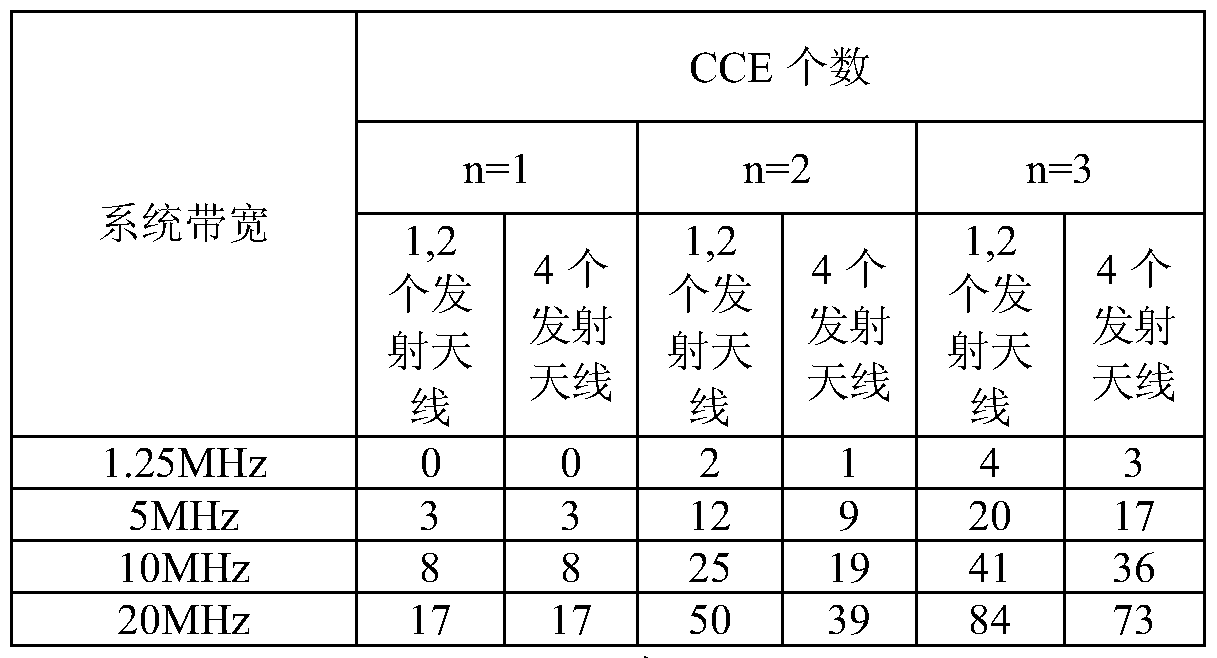
- the number n of symbols occupied by the PDCCH indicated by the PCFICH (Physical Layer Control Format Indicator Channel) in each downlink subframe may be 1, 2 or 3, and for the special subframe, n may be 1 or 2.
- the n value of a sub-frame can be dynamically changed.
- a downlink subframe if the system parameters such as the system bandwidth and the pilot antenna configuration are fixed, the more the number of symbols n occupied by the PDCCH, the more the number of CCEs in the downlink subframe.
- n is 1, 2, 3, vJ, N CCE N CCE , N CCEii represent the number of CCEs in the downlink subframe, N CQ ⁇ N CCE ⁇ N CCE , .
- the network side allocates an ACK channel to the user according to the following rules:
- the network side reserves f( N CC£ , 3 ) ACK channels for each downlink subframe (including special subframes) according to the maximum number of CCEs, and uses CCE and ACK.
- f(W ee£ 3 ) N ee£ 3
- the function f represents the mapping rule of the CCE label to the ACK channel label.
- each downlink sub-frame is mapped to each one in the original order, and the size of each copy is N e ⁇ 3.
- the mapping mode is as shown in FIG. 2, where the maximum value of the PCFICH of the downlink subframes 0 and 1 is 3.
- the embodiment of the present invention provides a technique for allocating an ACK channel to a user, which can save the required ACK channel resources.
- An embodiment of the present invention provides a method for allocating a response ACK channel for a user, which is used to feed back a response of N downlink subframes in an uplink subframe, where the method includes:
- the ACK channel is allocated to the downlink subframe according to the order of incrementing the mapping label d and incrementing the sub-block label m; where N is a positive integer.
- Another embodiment of the present invention provides a method for allocating a response ACK channel for a user, which is used to feed back a response of N downlink subframes in an uplink subframe, where the method includes:
- CCE is the CCE label of the control channel element in the sub-frame
- ⁇ is the sub-label of the d
- the label of the ACK channel assigned in the frame is ⁇ ⁇ CCE
- ⁇ ⁇ ⁇ ⁇ indicates the number of CCEs in the downlink subframe when the value of n is m
- K and N are positive integers.
- Another embodiment of the present invention provides a method for allocating an ACK channel for a user, which is used to feed back a response of N downlink subframes in one uplink subframe.
- the reserved ACK channel is divided into N large blocks, each downlink subframe corresponds to one large block in a preset order, and each large block is divided into multiple sub-blocks; according to different channels in the same subframe
- the control unit CCE sets are respectively mapped to different sub-blocks, and the ACK channel is allocated for the downlink subframe.
- the embodiment of the present invention further provides another method for allocating an ACK channel for a user, which is used to feed back a response of multiple downlink subframes in one uplink subframe.
- the reserved Wx Or ⁇ N CCE i ACK channels continuously mapping ACK channels for each downlink subframe.
- the embodiment of the present invention provides another method for allocating an ACK channel for a user, which is used to feed back a response of multiple downlink subframes in one uplink subframe.
- the reserved ACK channel is divided into N large blocks, and each downlink subframe is assigned a mapping label d according to a preset rule, and each mapping label corresponds to one large block; each large block is divided into multiple sub-blocks.
- the ACK channel is allocated for the downlink subframe according to the order of incrementing the mapping label d and incrementing the sub-block label m, where K is an integer greater than or equal to 1.
- the embodiment of the present invention provides another method for allocating an ACK channel for a user, which is used to feed back responses of multiple downlink subframes in one uplink subframe.
- the reserved ACK channel is divided into N large blocks, and the same mapping label d is assigned to multiple downlink subframes according to a preset rule, and each mapping label corresponds to one large block; each large block is divided into multiple sub-blocks.
- the ACK channel is allocated for the downlink subframe in the order of increasing the mapping label d and incrementing the sub-block label m.
- An embodiment of the present invention provides an apparatus for allocating a response ACK channel to a user, including a reservation unit and an allocation unit.
- the reserved unit is configured to reserve a channel for the N downlink subframes.
- the allocation unit is configured to divide the reserved ACK channel into N large blocks, and assign a mapping label d to each downlink subframe according to a preset rule. Each mapping label corresponds to one large block; each large block is divided into multiple sub-blocks, and the mapping is incremented according to the first The order of incrementing the sub-block number m is to allocate an ACK channel for the downlink subframe.
- the embodiment of the present invention further provides another apparatus for allocating a response ACK channel to a user, including: a reservation unit, configured to reserve A ⁇ W CC ? , max ⁇ M ⁇ or N ee £ for N downlink subframes, An M ACK channel; an allocating unit, configured to allocate an ACK channel for the downlink subframe according to how the ACK channel is continuously mapped for each subframe on the reserved ACK channel.
- a reservation unit configured to reserve A ⁇ W CC ? , max ⁇ M ⁇ or N ee £ for N downlink subframes, An M ACK channel
- an allocating unit configured to allocate an ACK channel for the downlink subframe according to how the ACK channel is continuously mapped for each subframe on the reserved ACK channel.
- Embodiments of the present invention also provide a communication system including a user terminal and any of the devices described above.
- the device is located on the network side, and allocates an ACK channel to the user terminal.
- the user terminal feeds back response information of the N downlink subframes to the network side on the allocated ACK channel.
- the reserved ACK channel is divided into large blocks according to the downlink subframe, and then the large block is divided into multiple sub-blocks, and the CCE sets of the control channel elements in the same subframe are respectively mapped to different sub-blocks, thereby
- the idle ACK channel resources are released in a block, forming more resource blocks for transmission of other channels, such as for PUSCH transmission.
- the ACK channel is continuously mapped for each subframe, thereby facilitating the free ACK channel resources to be released in a whole block to save ACK channel resources.
- FIG. 1 is a schematic structural diagram of a TDD mode frame in the prior art
- FIG. 2 is a schematic diagram of a mapping manner according to the prior art
- FIG. 3 is a schematic flow chart of a method according to an embodiment of the present invention.
- FIG. 4 is a schematic diagram of a mapping manner according to an embodiment of the present invention.
- FIG. 5 is a schematic diagram of another mapping manner according to an embodiment of the present invention.
- FIG. 6 is a schematic diagram of still another mapping manner according to an embodiment of the present invention
- FIG. 7 is a schematic structural view of a device according to an embodiment of the present invention.
- FIG. 8 is a schematic structural diagram of a system according to an embodiment of the present invention.
- the inventors have found that allocating an ACK channel to a user according to the prior art is disadvantageous for more idle ACK channels being released to form a resource block for PUSCH transmission.
- the ACK channel label that may be used in the ACK channel mapped to subframe 0 is 0 ⁇ N CCE
- 3 -1 can only be located in 0 ⁇ NCCEJ-1, numbered NCCEJ ⁇ N CCE, ACK channel 3-1, and can not pass through implicit mapping is occupied, these idle ACK channel resource occupied difficult to block the release, i.e., release of free resources is difficult to form a resource block.
- the network side allocates an ACK channel to the user according to the following rules:
- ⁇ , ⁇ ⁇ are reserved for each subframe (including special subframes) ( ⁇ channel, a total of X, MAX ⁇ ⁇ ⁇ channels are reserved.
- n 2
- n 3
- Max ⁇ Mi ⁇ is 3.
- the number of ACK channels reserved for each subframe is .
- each subframe corresponds to a large block in a preset order; the labels in the same subframe are ⁇ 0, 1 , NccE ⁇ - 1 ⁇ ,
- the CCE sets of 1, ..., N CCE, and Mi -1 ⁇ are mapped to different sub-blocks, respectively.
- step 102 The specific mapping process in step 102 will be described below by taking the 3GPP E-UTRA system with max ⁇ f ⁇ as 3 as an example.
- Max ⁇ Mi ⁇ is 3, that is, each chunk is divided into 3 sub-blocks.
- the label in the same sub-frame is ⁇ 0, 1,
- a unique mapping label d is assigned to the (o ⁇ ⁇ N) subframes of the N downlink subframes with the labeling i in accordance with the preset rule, to indicate that the subframes are ranked in the mapping.
- the frame is arranged in the last mapping mode, or the subframe with the largest value of n is ranked first in the mapping mode, especially according to the actual value of n from the largest to the smallest mapping mode.
- the ACK channel number assigned after mapping is n ⁇ CCH
- the N x N e ⁇ ACK channels reserved for N downlink subframes are respectively labeled 0 ⁇ N*N ee£>3 -l.
- the base station schedules a user terminal UE in the subframe labeled d of the N downlink subframes, and allocates a starting CCE label of the PDCCH occupied by the downlink scheduling assignment grant command of the UE to n CCE , Q.
- the UE detects the PDCCH carrying the UE downlink scheduling assignment grant command on the subframe labeled d, and learns that the initial CCE label occupied by the UE is eeE , 0 ⁇ n CCE ⁇ N CCE , 3 .
- the UE learns the ACK channel label assigned to it according to the following procedure! cai : First, it is determined by the value of the CE that the mapped ACK channel belongs to the sub-block labeled m in the subframe labeled d, and the determining process is from e.
- the UE feeds back ACK/NACK information on the labeled ACK channel, and the base station detects the fed back ACK/NACK information on the ACK channel labeled CCH . If the base station schedules the UE in multiple subframes of the N subframes, the base station allocates multiple ACK channel labels to the UE by using the foregoing mapping, and the UE generally uses the detected CCE corresponding to the start CCE of the last PDCCH. The ACK channel feeds back ACK/NACK information.
- the RB can be scheduled for user data only when L code division multiplexed ACK channels on the RB are not used. Therefore, the adjustment of the above sub-blocks can also be introduced into the "fine tuning", that is, the sub-frame number is ⁇ 0, 1, .., NccE ' 1 - 1 - ⁇ , ⁇ NCCEA — A N CCE, I - ⁇
- the order of ⁇ 1 is determined in turn to determine the respective values, and usually the value should be no more than 3. Introduction of regulatory factors The following is: When the number of ACK channels in different CCE sets of the same subframe is close to an integral multiple of L, a complete one or several RBs can be formed.
- the "preset order" in "one sub-frame corresponds to a large block in a preset order" may be the original order of the N downlink sub-frames, or may be a special sub-frame in the last order, or may be The subframe with the largest actual value of n is ranked in the first order (if there are multiple subframes with the same n value, the multiple subframes may be ranked first in any order), and any other may be beneficial for release.
- Each sub-frame corresponds to an example of a large block in the original order of N sub-frames, as shown in FIG.
- it is necessary to feed back ACK/NAK of two downlink subframes in one uplink subframe and Mi of both downlink subframes is 3.
- the value of n indicated by the PCFICH of the downlink subframe 0 is actually 3, and the value of n indicated by the PCFICH of the downlink subframe 1 is actually 2.
- the downlink subframes 0 and 1 occupy a large block in the order of the original subframe, that is, the first subframe 0 and the subframe 1 in sequence. Among them, in the sub-frames 0 and 1, each sub-block is sequentially occupied by the label.
- ACK channel resources whose numbers are in the range of i fN cc ⁇ 3 + N CCE ) ⁇ (2N m - 1 ) ⁇ can be released.
- each sub-frame corresponds to a large block in the last order of the special sub-frames. Since the value of the special subframe in the existing 3GPP system is at most 2, the special subframe is ranked last, which is beneficial to release more idle ACK channel resources in a whole block.
- Each sub-frame corresponds to a large block in the order in which the actual value of n is the largest, as shown in Figure 5.
- ACK/NAK of downlink subframe 0 and downlink subframe 1 in one uplink subframe and Mi of both downlink subframes is 3.
- the value of n indicated by the PCFICH of the downlink subframe 0 is actually 2, and the value of n indicated by the PCFICH of the downlink subframe 1 is actually 3. Since the value of n of the downlink subframe 1 is the largest, the downlink subframe 1 is ranked first.
- ACK channel resources in the range of the label ⁇ (N CCE , 3 + N ) ⁇ (2N CCE>3 - 1 ) ⁇ can be released.
- the number of downlink subframes to be fed back is greater than two, it is preferable to allocate the large blocks according to the actual value of the subframe n from the largest to the smallest, so that more idle ACK resources are released in a whole block. come out.
- the ACK/NAK of the N downlink subframes needs to be fed back in one uplink subframe, and the network side allocates an ACK channel to the user according to the following rules:
- step 101 The difference from step 101 is that it is not reserved for each subframe. Instead of ACK channels, different numbers of ACK channels are reserved according to the difference of Mi of each downlink subframe, so that reserved ACK channel resources can be reduced, thereby saving system channel resources.
- N ee £ and 2 ACK channels are reserved for the special subframe, and N e 3 channels are reserved for the remaining downlink subframes respectively.
- Reserving ⁇ , 2 instead of N CCEi ACK channels for special subframes reduces the reserved ACK channel resources.
- the CCE sets of N ccE, Mi -1 ⁇ are mapped to different sub-blocks, respectively. For example, for a special subframe with a Mi of 2, the corresponding large block is divided into 2 sub-blocks, and the label in the sub-frame is ⁇ 0, 1, Ncc ⁇ NccE '
- the CCE sets of NcCE ' 1 + 1 , ..., ( NccE ' 2 - 1 ) ⁇ are mapped to different sub-blocks, respectively.
- each chunk is divided into 3 sub-blocks, and sub-blocks belonging to different chunks are staggered, and the labels in the same subframe are ⁇ 0, 1, .., NccE - 1 - 1 ⁇ , ⁇ NccE - 1 , NccE - 1 + 1 , ..., ( NccE - 2 — 1 ) ⁇ ,
- the CCE sets of ⁇ NccE ' 2 , ( NccE ' 2 +1 ) , ..., ( CCE ' 3 - 1 ) ⁇ are mapped to different sub-blocks, respectively.
- the special subframe is ranked last, that is, when the mapping label d is assigned to the subframe labeled i, it is always special.
- step b the base station and the UE determine the ACK channel label ⁇ H mapped by the CCE labeled n CCE in the subframe labeled d according to the following procedure:
- the mapped value is determined by the value of ⁇ E
- the ACK channel belongs to the sub-block labeled m in the subframe labeled d, and the determination process is to select the value of m from me ⁇ 0, 1, 2 ⁇ such that N CCE , m ⁇ n CCE ⁇ N CCE , m+l -1 (1) is established;
- substituting the m value obtained in the previous step into the formula n ⁇ CCH (Nd- ⁇ )x N CCE>m +dx N CCE , m+l + n CCE ( 2 )
- the foregoing preset sequence may be the original sequence of the downlink subframes, or may be the order in which the special subframes are ranked last, or the subframes in which the actual value of ⁇ is the largest. Refer specifically to the description of the previous embodiment.
- the ACK/NAK of the downlink subframes needs to be fed back in one uplink subframe, and the network side allocates an ACK channel to the user according to the following rules:
- a. Reserve an ACK channel for each downlink subframe.
- W ca?, M or W ca?, max ⁇ M ⁇ ACK channels are reserved for each subframe, that is, a total of NxN CCE and dN CCE channels are reserved.
- b. Map N subframes onto the reserved ACK channel. Specifically, the ACK channel is continuously mapped for each subframe. The order of arrangement between N subframes may be any order. An example is shown in Figure 6. In The Mi of the frame is all 3. The value of n indicated by the PCFICH of the downlink subframe 0 is actually 2, and the value of n indicated by the PCFICH of the downlink subframe 1 is actually 3. After subframe 0 has mapped the ACK channel, subframe 1 then maps the remaining ACK channels. The method of continuous mapping can ensure that there is no idle ACK channel between the ACK channels mapped in each subframe, so that more idle ACK channels can be released in one block. In the example shown in Figure 6, the label is
- ACK channel resources in the range of 3 - J can be released.
- the released label is at f (N CCE , + N CC 2 ) ⁇ (2N CCE , - range
- the ACK channel within can form a complete resource block for transmission of the PUSCH.
- the ACK channel in the range of 145 can be released, that is, 34 ACK channels are released.
- a resource block can only multiplex 18 ACK channels, at least one resource block can be released for PUSCH transmission.
- 34 ACK channels can be released, but since the value of L is 18, 16 ACK channels are also released, but a complete RB cannot be formed for PUSCH transmission.
- the intra-subframe CCE and the ACK channel have a mapping relationship, and a non-overlapping ACK channel set is reserved for each sub-frame.
- the first method multiple downlink subframes are mapped to the same ACK channel set, and a one-to-one mapping of CCE labels to ACK channel labels is still used in the subframe, which is equivalent to allocating multiple downlink subframes in the mapping.
- the same mapping label d For the downlink subframe to which the same mapping label d is allocated, the number of reserved ACK channels is not less than the maximum number of CCEs of any one of the downlink subframes. For the 3GPP E-UTRA system, this means that if the same mapping label d is assigned to the special subframe and the normal downlink subframe, then there are N ee 85 ACK channels in their corresponding ACK channel set.
- the base station can notify the user of the allocation of the mapping label d through high layer signaling, for example, by means of broadcast notification.
- the second method is to reserve a set of ACK channels that do not overlap each other for each downlink subframe, but the mapping of the CCE label to the ACK channel label is not used in the subframe, but the same can be assigned to multiple CCEs.
- ACK channel A more common method is to reserve one ACK channel for every K consecutively labeled CCEs. Specific steps are as follows:
- NX INTEGER (N CCE , m , / or INTEGER (N CCEM IK) channels reserved for N downlink subframes are divided into two large blocks, each of which contains INTEGER (N CCE Mi , IK ) or INTEGER ⁇ CCE Mi IK) Channels; each downlink subframe is assigned a mapping label d according to a preset rule, and each mapping label corresponds to one large block.
- /NrEGEwo represents the rounding operation, which can be a rounding up operation "1, or a rounding down operation L". It can be seen that when K is greater than 1, it is equivalent to reducing the number of ACK channels to be reserved to 1/K of the number of CCEs, and thus K can also be referred to as an ACK resource reduction factor.
- N CCEmaMW ⁇ / channels are reserved, that is, INTEGER (N cc ⁇ maxiM] IK) ACK channels are reserved for each downlink subframe, each large block is divided into max ⁇ M ⁇ sub-blocks
- the sub-block labeled m contains INTEGER(N CCE m+1 1 K) - INTEGER ⁇ N CCE m / ) ACK channels, where
- each block is divided into ⁇ sub-blocks, and the sub-block labeled m contains INTEGER(N CCE m+l / K, — INTEGER(N CCE m / K, CKAt, where 0 ⁇ ⁇ M'. All ACK channel sub-blocks are arranged in the order of increasing the mapping label and incrementing the sub-block label m.
- 1 PDCCH can be 1 It is composed of 2, 4 or 8 CCEs. Therefore, the value range of K is recommended to be a non-empty subset of the set ⁇ 1, 2, 4, 8 ⁇ . The specific value of K is notified to the user by the base station through high-level signaling.
- CCE ACK channel label ⁇ H First, to determine ACK channel is mapped by ⁇ £ values belonging to the designated subframe d numerals into sub-blocks of m, e.g., for 3GPP E-UTRA system, the process of determining from me The value of m is chosen in ⁇ 0,1,2 ⁇
- a plurality of CCEs may be mapped to the same ACK channel for the partial subframes, and a mapping manner of each CCE corresponding to the different ACK channels, that is, the CCE label to the ACK channel label, may be extracted for other partial subframes.
- - Mapping method a mapping manner of each CCE corresponding to the different ACK channels, that is, the CCE label to the ACK channel label.
- the remaining CCEs in the sub-frame after the rounding operation on the ⁇ may not have an ACK channel corresponding thereto, for example, when the label is
- the subframe of i reserves Lw ee£ , M / " ACK channel, when N ee £ , M cannot be divisible by K, according to equations (3) and (4), only the label is 0 ⁇ Lw CC£ .
- the CCE of M / "x -l can be mapped to the ACK channel, labeled Therefore, on the base station side, the label is not ⁇ N CCE , Mi -1 CCE allocation is used to carry the downlink scheduling assignment authorization command
- the starting CCE occupied by the PDCCH is the starting CCE occupied by the PDCCH.
- the first method in order to avoid collision of the ACK channels of the plurality of downlink subframes to which the same mapping label d is allocated, some restrictions may be imposed. For example, in a CCE with the same label in the multiple downlink subframes to which the same mapping label d is assigned, at most one CCE is the initial CCE occupied by the PDCCH carrying the downlink scheduling assignment authorization command.
- an apparatus 701 for assigning a response ACK channel to a user is shown in FIG.
- the device 701 includes a reservation unit 702 and an allocation unit 703.
- the reservation unit 702 is configured to reserve a channel for each downlink subframe (including a special subframe), for example, reserve /NrEGE?(N ee£ , maxiMi / ⁇ ) for each subframe or
- the allocating unit 703 is configured to allocate the reserved ACK channel to the N downlink subframes, specifically: dividing the reserved ACK channel into N large blocks, and each downlink sub-subject according to a preset rule.
- the frame is assigned a mapping label d, and each mapping label corresponds to one large block, and each large block is divided into multiple
- the sub-block allocates an ACK channel for each downlink subframe in the order of increasing the mapping label d and incrementing the sub-block label m.
- the preset rule may be that the special subframe is arranged in the last mapping manner, or may be the mapping mode in which the subframe with the largest actual value of n is ranked first, especially according to the actual value of n from large to small. the way.
- each large block is divided into max ⁇ f ⁇ sub-blocks, labeled as m Included in the sub-block
- N CCE / 1 letter divide each large block into M sub-blocks, and the sub-block labeled m contains INTEGER(N CCE M+L IK) - INTEGER(N CCE M IK) channels.
- the distribution method it can be:
- the reservation unit 702 is configured to reserve N CCE , m for each downlink subframe, or
- the allocation unit 703 allocates an ACK channel for the downlink subframe according to the manner in which the ACK channel is continuously mapped for each subframe on the reserved ACK channel.
- a communication system 801 is shown in FIG.
- Communication system 801 includes means 802 and user terminal 803 that assign a response ACK channel to the user.
- the device 802 further includes a reservation unit and an allocation unit, and the functions of the two units are the same as the reservation unit 802 and the allocation unit 803, respectively.
- the device 802 is located on the network side, such as in a base station on the network side. Since the user terminal knows the allocation rule of the ACK channel in advance, the response information of the N downlink subframes is directly fed back to the network side on the allocated ACK channel.
Description


Claims
Priority Applications (13)
| Application Number | Priority Date | Filing Date | Title |
|---|---|---|---|
| JP2010509668A JP5001426B2 (ja) | 2008-04-29 | 2009-04-01 | Ackチャネルをユーザに割り当てるための方法、装置、及びシステム |
| ES09709439.5T ES2523040T3 (es) | 2008-04-29 | 2009-04-01 | Método, dispositivo y sistema para la asignación de canales de acuse de recibo a los usuarios |
| EP19219962.8A EP3672198B1 (en) | 2008-04-29 | 2009-04-01 | Method, device and system for assigning ack channels to users |
| BRPI0907017A BRPI0907017B8 (pt) | 2008-04-29 | 2009-04-01 | método, dispositivo e sistema para designação de canais de aviso de recebimento para usuários |
| CN2009800000634A CN101690115B (zh) | 2008-04-29 | 2009-04-01 | 为用户分配应答信道的方法、装置和系统 |
| EP17188077.6A EP3282673B1 (en) | 2008-04-29 | 2009-04-01 | Method, device and system for assigning ack channels to users |
| EP09709439.5A EP2278772B1 (en) | 2008-04-29 | 2009-04-01 | A method, apparatus and system for allocating response channel to user |
| US12/543,005 US8243669B2 (en) | 2008-04-29 | 2009-08-18 | Method, device and system for assigning ACK channels to users |
| US13/286,844 US8213378B2 (en) | 2008-04-29 | 2011-11-01 | Method, device and system for assigning ACK channels to users |
| US13/550,317 US8665814B2 (en) | 2008-04-29 | 2012-07-16 | Method, device and system for assigning ACK channels to users |
| US14/104,782 US9054867B2 (en) | 2008-04-29 | 2013-12-12 | Method, device and system for assigning ACK channels to users |
| US14/732,159 US9306705B2 (en) | 2008-04-29 | 2015-06-05 | Method, device and system for assigning ACK channels to users |
| US15/050,674 US9525517B2 (en) | 2008-04-29 | 2016-02-23 | Method, device and system for assigning ACK channels to users |
Applications Claiming Priority (4)
| Application Number | Priority Date | Filing Date | Title |
|---|---|---|---|
| CN200810067047 | 2008-04-29 | ||
| CN200810067047.4 | 2008-04-29 | ||
| CN200810108466.8 | 2008-06-02 | ||
| CN2008101084668A CN101500260B (zh) | 2008-04-29 | 2008-06-02 | 为用户分配应答信道的方法、装置和系统 |
Related Child Applications (1)
| Application Number | Title | Priority Date | Filing Date |
|---|---|---|---|
| US12/543,005 Continuation US8243669B2 (en) | 2008-04-29 | 2009-08-18 | Method, device and system for assigning ACK channels to users |
Publications (1)
| Publication Number | Publication Date |
|---|---|
| WO2009132543A1 true WO2009132543A1 (zh) | 2009-11-05 |
Family
ID=40947088
Family Applications (1)
| Application Number | Title | Priority Date | Filing Date |
|---|---|---|---|
| PCT/CN2009/071124 WO2009132543A1 (zh) | 2008-04-29 | 2009-04-01 | 为用户分配应答信道的方法、装置和系统 |
Country Status (8)
| Country | Link |
|---|---|
| US (6) | US8243669B2 (zh) |
| EP (4) | EP3672198B1 (zh) |
| JP (4) | JP5001426B2 (zh) |
| CN (6) | CN102291768B (zh) |
| BR (1) | BRPI0907017B8 (zh) |
| ES (2) | ES2643597T3 (zh) |
| HU (1) | HUE034634T2 (zh) |
| WO (1) | WO2009132543A1 (zh) |
Cited By (2)
| Publication number | Priority date | Publication date | Assignee | Title |
|---|---|---|---|---|
| CN102123501A (zh) * | 2010-01-08 | 2011-07-13 | 电信科学技术研究院 | Ack/nak资源的确定方法和设备 |
| JP2011166385A (ja) * | 2010-02-08 | 2011-08-25 | Kyocera Corp | 基地局及び基地局の通信方法 |
Families Citing this family (29)
| Publication number | Priority date | Publication date | Assignee | Title |
|---|---|---|---|---|
| CN102291768B (zh) | 2008-04-29 | 2014-01-22 | 华为技术有限公司 | 为用户分配应答信道的方法、装置和系统 |
| US8730878B2 (en) * | 2008-08-20 | 2014-05-20 | Qualcomm Incorporated | Power and resource efficient APPDU based approach with scheduled block ACKS for WLAN |
| EP2296408A1 (en) * | 2009-09-14 | 2011-03-16 | Alcatel Lucent | A method for scheduling transmissions between a base station and user terminals, a base station and a communication network therefor |
| CN102014496B (zh) | 2009-10-16 | 2013-07-31 | 电信科学技术研究院 | 一种上行控制信道资源配置方法、设备和系统 |
| CN101815325B (zh) * | 2010-03-09 | 2012-05-23 | 上海华为技术有限公司 | 跳频的实现方法、装置和通信系统 |
| US8644199B2 (en) | 2010-03-31 | 2014-02-04 | Samsung Electronics Co., Ltd | Indexing resources for transmission of acknowledgement signals in multi-cell TDD communication systems |
| US9197388B2 (en) * | 2010-05-25 | 2015-11-24 | Kyocera Corporation | Radio base station and control method for the same |
| CN102377475B (zh) * | 2010-08-19 | 2014-03-12 | 大唐移动通信设备有限公司 | 一种确定下行子帧的控制区符号数的方法及装置 |
| EP3731445B1 (en) | 2010-09-28 | 2023-11-01 | Lg Electronics Inc. | Method and apparatus for transmitting reception confirmation in wireless system |
| JP4923161B1 (ja) | 2010-09-29 | 2012-04-25 | シャープ株式会社 | 移動通信システム、移動局装置、基地局装置、通信方法および集積回路 |
| EP2437422A1 (en) * | 2010-10-01 | 2012-04-04 | Panasonic Corporation | Search space for uplink and downlink grant in an OFDM-based mobile communication system |
| JP5835588B2 (ja) * | 2010-11-09 | 2015-12-24 | シャープ株式会社 | 移動局装置、基地局装置、無線通信システム、無線通信方法および集積回路 |
| CN102843732B (zh) * | 2011-06-20 | 2015-11-25 | 华为技术有限公司 | 一种时分双工tdd通信方法、基站和用户设备 |
| JP5895388B2 (ja) * | 2011-07-22 | 2016-03-30 | シャープ株式会社 | 端末装置、基地局装置、集積回路および通信方法 |
| CN102271032B (zh) * | 2011-08-09 | 2014-11-19 | 电信科学技术研究院 | 一种实现上行反馈的方法、系统及装置 |
| US8953532B2 (en) * | 2011-09-19 | 2015-02-10 | Futurewei Technologies, Inc. | Method and apparatus for uplink control signaling |
| US8774848B2 (en) | 2011-10-11 | 2014-07-08 | Fujitsu Limited | System and method for enhancing cell-edge performance in a wireless communication network |
| EP2797356A4 (en) | 2011-12-23 | 2015-09-09 | Fujitsu Ltd | METHOD AND APPARATUS FOR RESOURCE MAPPING FOR DOWNLINK CONTROL CHANNEL |
| CN106788929B (zh) * | 2012-01-09 | 2020-01-17 | 华为技术有限公司 | 一种控制信道资源映射方法、基站及用户设备 |
| EP2870811B1 (en) * | 2012-07-06 | 2018-12-19 | Telefonaktiebolaget LM Ericsson (publ) | Method and network node for allocating resources of an uplink subframe |
| WO2014048472A1 (en) | 2012-09-27 | 2014-04-03 | Huawei Technologies Co., Ltd. | Methods and nodes in a wireless communication system |
| US10652921B2 (en) | 2015-05-27 | 2020-05-12 | Qualcomm Incorporated | Techniques for handling feedback for downlink transmissions in a shared radio frequency spectrum band |
| RU2638544C2 (ru) * | 2016-06-03 | 2017-12-14 | Фудзицу Лимитед | Способ и устройство для отображения ресурсов физического канала управления нисходящей линии связи |
| CN107645356B (zh) * | 2016-07-20 | 2020-12-25 | 普天信息技术有限公司 | Pdcch的控制信道单元聚合等级确定方法和装置 |
| US10251172B2 (en) * | 2016-08-25 | 2019-04-02 | Qualcomm Incorporated | Supporting different numerology configurations |
| US10764867B2 (en) | 2016-09-27 | 2020-09-01 | Lg Electronics Inc. | Method and device for selecting resource and transmitting PSSCH in wireless communication system |
| CN110169118B (zh) * | 2017-01-13 | 2023-05-26 | Lg电子株式会社 | 在无线通信系统中基于服务质量(QoS)流发送UL分组的方法及装置 |
| CN109039554B (zh) * | 2017-06-09 | 2021-01-26 | 上海朗帛通信技术有限公司 | 一种被用于窄带通信的用户设备、基站中的方法和装置 |
| US11147065B2 (en) * | 2018-01-22 | 2021-10-12 | Qualcomm Incorporated | Feedback bit reservation for uplink control piggybacking |
Citations (4)
| Publication number | Priority date | Publication date | Assignee | Title |
|---|---|---|---|---|
| WO2004072673A2 (en) * | 2003-02-13 | 2004-08-26 | Nokia Corporation | System and method for improved uplink signal detection and reduced uplink signal power |
| KR20060082129A (ko) * | 2005-01-11 | 2006-07-14 | 삼성전자주식회사 | 무선 통신 시스템에서 채널 할당 장치 및 방법 |
| KR20080008480A (ko) * | 2006-07-20 | 2008-01-24 | 삼성전자주식회사 | 직교 주파수 분할 다중 접속 시스템에서 피드백 채널을할당하는 장치 및 방법 |
| CN101127584A (zh) * | 2006-08-15 | 2008-02-20 | 华为技术有限公司 | 反馈及接收ack/nak信息的方法和装置 |
Family Cites Families (13)
| Publication number | Priority date | Publication date | Assignee | Title |
|---|---|---|---|---|
| CN1205834C (zh) | 2000-03-23 | 2005-06-08 | 西门子移动通讯公司 | 无线通信系统中的接入信道安排 |
| FR2833862B1 (fr) | 2001-12-21 | 2004-10-15 | Rhodia Elect & Catalysis | Dispersion colloidale organique de particules de fer, son procede de preparation et son utilisation comme adjuvant de carburant pour moteurs a combustion interne |
| US7158802B2 (en) * | 2002-02-19 | 2007-01-02 | Interdigital Technology Corporation | Method and apparatus for providing a highly reliable ACK/NACK for time division duplex (TDD) and frequency division duplex (FDD) |
| KR101042813B1 (ko) * | 2004-02-17 | 2011-06-20 | 삼성전자주식회사 | 시분할 듀플렉싱 이동 통신 시스템에서 상향 방향 전송증대를 위한 데이터 수신 여부 정보를 전송하는 방법 |
| KR100714945B1 (ko) * | 2005-10-12 | 2007-05-07 | 엘지노텔 주식회사 | 오에프디엠에이 시스템에서의 부채널 할당 장치 및 방법 |
| US9143288B2 (en) * | 2006-07-24 | 2015-09-22 | Qualcomm Incorporated | Variable control channel for a wireless communication system |
| US8068457B2 (en) | 2007-03-13 | 2011-11-29 | Samsung Electronics Co., Ltd. | Methods for transmitting multiple acknowledgments in single carrier FDMA systems |
| CN101127581B (zh) | 2007-09-07 | 2010-09-08 | 普天信息技术研究院有限公司 | 一种ldpc编码调制的映射及逆映射方法和设备 |
| CN101222291B (zh) | 2008-01-05 | 2013-06-12 | 中兴通讯股份有限公司 | 用于物理上行控制信道的发送方法和装置 |
| CN101505208A (zh) | 2008-02-04 | 2009-08-12 | 三星电子株式会社 | 分配上行ack/nack信道的方法 |
| CN102017506B (zh) * | 2008-03-16 | 2014-06-04 | Lg电子株式会社 | 在无线通信系统中执行混合自动重传请求(harq)的方法 |
| US8837421B2 (en) | 2008-03-26 | 2014-09-16 | Nokia Siemens Neworks Oy | Channelization procedure for implementing persistent ACK/NACK and scheduling request |
| CN102291768B (zh) | 2008-04-29 | 2014-01-22 | 华为技术有限公司 | 为用户分配应答信道的方法、装置和系统 |
-
2008
- 2008-06-02 CN CN201110264130.2A patent/CN102291768B/zh active Active
- 2008-06-02 CN CN2008101084668A patent/CN101500260B/zh active Active
- 2008-06-02 CN CN201110264190.4A patent/CN102291769B/zh active Active
- 2008-06-02 CN CN2011101195959A patent/CN102149148B/zh active Active
- 2008-06-02 CN CN2011102634864A patent/CN102291767B/zh active Active
-
2009
- 2009-04-01 EP EP19219962.8A patent/EP3672198B1/en active Active
- 2009-04-01 JP JP2010509668A patent/JP5001426B2/ja active Active
- 2009-04-01 EP EP14167643.7A patent/EP2765755B1/en active Active
- 2009-04-01 EP EP09709439.5A patent/EP2278772B1/en active Active
- 2009-04-01 ES ES14167643.7T patent/ES2643597T3/es active Active
- 2009-04-01 ES ES09709439.5T patent/ES2523040T3/es active Active
- 2009-04-01 BR BRPI0907017A patent/BRPI0907017B8/pt active IP Right Grant
- 2009-04-01 HU HUE14167643A patent/HUE034634T2/en unknown
- 2009-04-01 CN CN2009800000634A patent/CN101690115B/zh active Active
- 2009-04-01 EP EP17188077.6A patent/EP3282673B1/en active Active
- 2009-04-01 WO PCT/CN2009/071124 patent/WO2009132543A1/zh active Application Filing
- 2009-08-18 US US12/543,005 patent/US8243669B2/en active Active
-
2011
- 2011-11-01 US US13/286,844 patent/US8213378B2/en active Active
-
2012
- 2012-05-17 JP JP2012113367A patent/JP5363611B2/ja active Active
- 2012-07-16 US US13/550,317 patent/US8665814B2/en active Active
-
2013
- 2013-09-04 JP JP2013182842A patent/JP5775126B2/ja active Active
- 2013-12-12 US US14/104,782 patent/US9054867B2/en active Active
-
2015
- 2015-06-05 US US14/732,159 patent/US9306705B2/en active Active
- 2015-07-02 JP JP2015133493A patent/JP6103551B2/ja active Active
-
2016
- 2016-02-23 US US15/050,674 patent/US9525517B2/en active Active
Patent Citations (4)
| Publication number | Priority date | Publication date | Assignee | Title |
|---|---|---|---|---|
| WO2004072673A2 (en) * | 2003-02-13 | 2004-08-26 | Nokia Corporation | System and method for improved uplink signal detection and reduced uplink signal power |
| KR20060082129A (ko) * | 2005-01-11 | 2006-07-14 | 삼성전자주식회사 | 무선 통신 시스템에서 채널 할당 장치 및 방법 |
| KR20080008480A (ko) * | 2006-07-20 | 2008-01-24 | 삼성전자주식회사 | 직교 주파수 분할 다중 접속 시스템에서 피드백 채널을할당하는 장치 및 방법 |
| CN101127584A (zh) * | 2006-08-15 | 2008-02-20 | 华为技术有限公司 | 反馈及接收ack/nak信息的方法和装置 |
Non-Patent Citations (1)
| Title |
|---|
| See also references of EP2278772A4 * |
Cited By (3)
| Publication number | Priority date | Publication date | Assignee | Title |
|---|---|---|---|---|
| CN102123501A (zh) * | 2010-01-08 | 2011-07-13 | 电信科学技术研究院 | Ack/nak资源的确定方法和设备 |
| CN102123501B (zh) * | 2010-01-08 | 2014-02-05 | 电信科学技术研究院 | Ack/nak资源的确定方法和设备 |
| JP2011166385A (ja) * | 2010-02-08 | 2011-08-25 | Kyocera Corp | 基地局及び基地局の通信方法 |
Also Published As
Similar Documents
| Publication | Publication Date | Title |
|---|---|---|
| WO2009132543A1 (zh) | 为用户分配应答信道的方法、装置和系统 | |
| WO2017157181A1 (zh) | 一种资源调度和分配的方法和装置 | |
| US11343841B2 (en) | Uplink resource scheduling in multiple time instances | |
| EP3869719B1 (en) | Method and device for transmitting uplink control information | |
| WO2018030069A1 (ja) | 端末及び通信方法 | |
| KR20120093084A (ko) | 응답 채널 자원들을 할당하는 방법 및 장치 | |
| WO2013004159A1 (zh) | 传输控制信道指示信息的方法、基站和用户设备 | |
| WO2012113330A1 (zh) | 信息传输的方法和装置 | |
| WO2012175019A1 (zh) | 一种时分双工tdd通信方法、基站和用户设备 | |
| WO2012167489A1 (zh) | 传输数据的方法和设备 | |
| WO2010108313A1 (zh) | 一种信道分配方法及装置 |
Legal Events
| Date | Code | Title | Description |
|---|---|---|---|
| WWE | Wipo information: entry into national phase |
Ref document number: 200980000063.4 Country of ref document: CN |
|
| WWE | Wipo information: entry into national phase |
Ref document number: 2009709439 Country of ref document: EP |
|
| WWE | Wipo information: entry into national phase |
Ref document number: 2010509668 Country of ref document: JP |
|
| WWE | Wipo information: entry into national phase |
Ref document number: 4277/KOLNP/2009 Country of ref document: IN |
|
| 121 | Ep: the epo has been informed by wipo that ep was designated in this application |
Ref document number: 09709439 Country of ref document: EP Kind code of ref document: A1 |
|
| NENP | Non-entry into the national phase |
Ref country code: DE |
|
| ENP | Entry into the national phase |
Ref document number: PI0907017 Country of ref document: BR Kind code of ref document: A2 Effective date: 20100629 |