WO2009118877A1 - 空調管理装置、空調管理システム - Google Patents
空調管理装置、空調管理システム Download PDFInfo
- Publication number
- WO2009118877A1 WO2009118877A1 PCT/JP2008/056009 JP2008056009W WO2009118877A1 WO 2009118877 A1 WO2009118877 A1 WO 2009118877A1 JP 2008056009 W JP2008056009 W JP 2008056009W WO 2009118877 A1 WO2009118877 A1 WO 2009118877A1
- Authority
- WO
- WIPO (PCT)
- Prior art keywords
- air conditioning
- file
- conditioning management
- server
- remote
- Prior art date
Links
Images


Classifications
-
- F—MECHANICAL ENGINEERING; LIGHTING; HEATING; WEAPONS; BLASTING
- F24—HEATING; RANGES; VENTILATING
- F24F—AIR-CONDITIONING; AIR-HUMIDIFICATION; VENTILATION; USE OF AIR CURRENTS FOR SCREENING
- F24F11/00—Control or safety arrangements
- F24F11/30—Control or safety arrangements for purposes related to the operation of the system, e.g. for safety or monitoring
-
- F—MECHANICAL ENGINEERING; LIGHTING; HEATING; WEAPONS; BLASTING
- F24—HEATING; RANGES; VENTILATING
- F24F—AIR-CONDITIONING; AIR-HUMIDIFICATION; VENTILATION; USE OF AIR CURRENTS FOR SCREENING
- F24F11/00—Control or safety arrangements
- F24F11/50—Control or safety arrangements characterised by user interfaces or communication
- F24F11/52—Indication arrangements, e.g. displays
-
- F—MECHANICAL ENGINEERING; LIGHTING; HEATING; WEAPONS; BLASTING
- F24—HEATING; RANGES; VENTILATING
- F24F—AIR-CONDITIONING; AIR-HUMIDIFICATION; VENTILATION; USE OF AIR CURRENTS FOR SCREENING
- F24F11/00—Control or safety arrangements
- F24F11/50—Control or safety arrangements characterised by user interfaces or communication
- F24F11/56—Remote control
- F24F11/58—Remote control using Internet communication
-
- F—MECHANICAL ENGINEERING; LIGHTING; HEATING; WEAPONS; BLASTING
- F24—HEATING; RANGES; VENTILATING
- F24F—AIR-CONDITIONING; AIR-HUMIDIFICATION; VENTILATION; USE OF AIR CURRENTS FOR SCREENING
- F24F11/00—Control or safety arrangements
- F24F11/62—Control or safety arrangements characterised by the type of control or by internal processing, e.g. using fuzzy logic, adaptive control or estimation of values
-
- F—MECHANICAL ENGINEERING; LIGHTING; HEATING; WEAPONS; BLASTING
- F24—HEATING; RANGES; VENTILATING
- F24F—AIR-CONDITIONING; AIR-HUMIDIFICATION; VENTILATION; USE OF AIR CURRENTS FOR SCREENING
- F24F11/00—Control or safety arrangements
- F24F11/50—Control or safety arrangements characterised by user interfaces or communication
- F24F11/54—Control or safety arrangements characterised by user interfaces or communication using one central controller connected to several sub-controllers
Definitions
- the present invention relates to an air conditioning management apparatus that controls the operation of air conditioning equipment, and an air conditioning management system that manages air conditioning equipment via a network.
- the present invention has been made to solve the above-described problems.
- An air conditioning management apparatus capable of remotely monitoring and controlling air conditioning equipment with the same ease as viewing a homepage while ensuring security.
- the purpose is to provide.
- An air conditioning management device is an air conditioning management device that controls the operation of an air conditioning device, the facility device interface connected to the air conditioning device, the remote interface connected to a network, and the facility device interface via the facility device interface.
- An equipment communication management unit that communicates with an air conditioner to obtain operation state data representing the operation state of the air conditioner, and generates an operation state file based on the content of the operation state data and the operation state via the remote interface.
- a remote communication management unit that transmits the file to a predetermined destination on the network.
- the air conditioning management device of the present invention since the operation state file is transmitted from the air conditioning management device to a destination on the network, the administrator only needs to view the operation state file transmitted to the destination via the Internet.
- the network itself that connects the equipment and the air conditioning management device does not need to be disclosed to the Internet. Therefore, it is safe from the viewpoint of information security without being subjected to mischief or attacks from malicious users on the Internet.
- FIG. 1 is a configuration diagram of an air conditioning management system according to Embodiment 1.
- FIG. It is a figure explaining the method of monitoring and controlling the air conditioner 100 from the remote monitoring terminal 500.
- FIG. 2 is a functional block diagram of the air conditioner 100.
- FIG. 3 is a functional block diagram of an air conditioning management device 200.
- FIG. 3 is a functional block diagram of a Web server 400.
- FIG. 4 is a functional block diagram of a remote monitoring terminal 500.
- FIG. 3 is a diagram illustrating an example of a folder configuration in a storage unit 430 of a Web server 400.
- FIG. 10 is a functional block diagram of a remote monitoring terminal 500 according to a fourth embodiment. It is a figure which shows the operation
- FIG. FIG. 1 is a configuration diagram of an air conditioning management system according to Embodiment 1 of the present invention.
- the air conditioning management system according to the first embodiment includes air conditioning devices 100a to 100b, air conditioning management devices 200a to 200c, and a local monitoring terminal 300 in a facility having one or more buildings.
- a Web server 400 is connected via the Internet 30, and a remote monitoring terminal 500 similarly connected to the Internet 30 is provided at a remote location.
- the air conditioners 100a to 100b and the air conditioning management devices 200a to 200c have the same configuration.
- an air conditioning device 100 an air conditioning management device 200, and the like.
- the air conditioning device 100 and the air conditioning management device 200 are connected to each other via a dedicated communication line 10 and can transmit and receive data by communication.
- the air conditioning management devices 200a to 200c and the local monitoring terminal 300 are connected to each other via the LAN 20, and can transmit and receive data by communication.
- the LAN 20 is connected to the Internet 30 via the Internet connection router 600.
- the air conditioner 100 corresponds to the “air conditioner” in the first embodiment.
- the air conditioning management device 200 is a device that monitors and controls a plurality of air conditioning devices 100 in an integrated manner.
- the local monitoring terminal 300 is configured by a general-purpose personal computer that operates a Web browser. The user can monitor and set the air conditioner operating state, abnormality information, and various operation data on the Web browser of the local monitoring terminal 300.
- the Web server 400 is a server for publishing a Web page on the Internet, and includes storage means such as an HDD (Hard Disk Drive) that stores an operation state file and a control command file described later.
- the remote monitoring terminal 500 can be configured by a general-purpose personal computer that operates a Web browser. The user uses the Web browser of the remote monitoring terminal 500 to connect to the Internet 30 to monitor and control the air conditioner 100. A specific method will be described later.
- Each device connected to the LAN 20 under the Internet connection router 600 is assigned a private IP address.
- the Internet connection router 600 executes NAT (Network Address Translation) when relaying a packet from the subordinate LAN 20 to the Internet 30.
- NAT Network Address Translation
- the air conditioning management device 200 and the local monitoring terminal 300 can connect to the Web server 400 via the Internet connection router 600 to the Internet 30 and acquire the files stored in the Web server 400. it can.
- the Internet 30 cannot connect to the LAN 20 under the Internet connection router 600.
- the remote monitoring terminal 500 cannot directly acquire the operating state of the air conditioning equipment 100 or the like. . Therefore, in the air conditioning management system according to the first embodiment, in order to monitor and control the air conditioning equipment 100 from the remote monitoring terminal 500, a method as described in FIG.
- FIG. 2 is a diagram for explaining a method for monitoring and controlling the air conditioner 100 from the remote monitoring terminal 500. Hereinafter, each procedure of FIG. 2 will be described. In FIG. 2, it is added that a part of the configuration and reference numerals in FIG. 1 are omitted.
- the air conditioning management device 200 periodically acquires the operating state of the air conditioner 100. When the operating state of the air conditioner 100 changes, the air conditioner 100 may automatically notify the air conditioning management device 200 of the contents.
- the air conditioning management device 200 transmits the operating state of the air conditioner 100 to the Web server 400 as an operating state file. You may make it transmit regularly, and you may transmit only when the driving
- the Web server 400 stores the operation state file in the storage unit.
- the user accesses the Web server 400 using the Web browser of the remote monitoring terminal 500 and requests transmission of the above-described operation state file. The user monitors the operation state of the air conditioner 100 by browsing the acquired operation state file on the Web browser.
- Control of air conditioner 100 (b.1) The user inputs a control command for the air conditioner 100 using the Web browser of the remote monitoring terminal 500.
- the remote monitoring terminal 500 generates a control command file based on the input and transmits it to the Web server 400.
- Web server 400 stores the control command file in the storage means.
- the air conditioning management apparatus 200 periodically requests the Web server 400 to transmit the above-described control command file stored in the Web server 400.
- the air conditioning management device 200 executes the control command instructed in the acquired control command file, and controls the air conditioning equipment 100.
- control performed from the remote monitoring terminal 500 can be arbitrarily configured. For example, an operation on the air conditioner 100 may be performed, a schedule for the air conditioner management apparatus 200, a setting such as energy saving, or the air conditioner management apparatus 200 may be instructed to periodically acquire the operating state of the air conditioner 100.
- the remote monitoring and control method described with reference to FIG. 2 it is not necessary to permit access from the Internet 30 side to the air conditioner 100 or the air conditioning management device 200, and access from the air conditioning management device 200 to the Web server It is possible to monitor and control the air-conditioning apparatus 100 from the remote monitoring terminal 500 only by permitting the control.
- the remote monitoring terminal 500 monitors and controls the air conditioning equipment 100
- the monitoring and control of the air conditioning management apparatus 200 can also be performed by the same procedure. The same applies to the following embodiments.
- a private IP address is assigned to each device connected to the LAN 20 so that the Internet 30 cannot be accessed from the Internet 30. Configured. Thereby, the network security of these apparatuses can be improved as compared with a network configuration in which the air conditioning apparatus 100 and the air conditioning management apparatus 200 connected to the LAN 20 can be directly accessed from the Internet 30.
- the air conditioning management apparatus 200 periodically acquires operating state data representing the operating state of the air conditioner 100 and transmits it to the Web server 400.
- the remote monitoring terminal 500 The operation state file stored in the Web server 400 is acquired, and the operation state of the air conditioner 100 is acquired.
- the remote monitoring terminal 500 can monitor the operating state of the air conditioner 100 without directly accessing the LAN 20, so that the remote control terminal 500 can remotely control the air conditioner 100 while maintaining the network security of each device connected to the LAN 20. Monitoring can be realized.
- the remote monitoring terminal 500 transmits a control command file describing a control command for the air conditioning device 100 to the Web server 400, and the air conditioning management device 200 transmits the control command file to the Web server 400.
- the stored control command file is periodically acquired to control the air conditioner 100.
- the remote monitoring terminal 500 can control the air conditioner 100 without directly accessing the LAN 20, so that remote control of the air conditioner 100 can be performed while maintaining the network security of each device connected to the LAN 20. Can be realized.
- Embodiment 2 FIG. In the first embodiment, the network configuration of the air conditioning management system according to the present invention and the remote monitoring and control technique have been described. In Embodiment 2 of the present invention, an example of the detailed configuration and operation of each device constituting the air conditioning management system will be described.
- FIG. 3 is a functional block diagram of the air conditioner 100.
- the air conditioner 100 includes a control unit 110, a sensor 120, a storage unit 130, and a communication management unit 140.
- the control unit 110 controls the normal operation of the air conditioner 100 and controls the operation state by reflecting the detection result of the sensor 120.
- operation state data 131 representing the operation state of the air conditioner 100 is created and stored in the storage unit 130.
- the creation of the driving state data 131 is executed at an appropriately determined timing such as when the driving state changes or at a predetermined time interval.
- the sensor 120 detects the temperature and pressure of each part of the air conditioner 100.
- the storage unit 130 stores operating state data 131 and model information 132 of the air conditioner 100.
- the model information 132 may be stored in the storage unit 130 in advance, or may be set by a user input.
- the communication management unit 140 communicates with the air conditioning management device 200.
- the control unit 110 can be configured by hardware such as a circuit device that realizes the function, or is configured by an arithmetic device such as a microcomputer or a CPU (Central Processing Unit), and software that defines the operation thereof. You can also
- the storage unit 130 can be configured by a storage device such as an HDD or a flash ROM (Read Only Memory).
- the communication management unit 140 includes a communication interface necessary for connecting to the air conditioning management device 200.
- FIG. 4 is a functional block diagram of the air conditioning management device 200. Although FIG. 4 shows a functional block diagram of the air conditioning management device 200a, other air conditioning management devices have the same configuration.
- the air conditioning management device 200 is a device that monitors and controls the air conditioning equipment 100 deployed in a facility having one or more buildings, and includes a display device 210, an input device 220, an equipment interface 230, a remote interface 240, A control unit 250 and a storage unit 260 are provided.
- the display device 210 displays the operation state of the air conditioner 100 on the screen.
- the input device 220 is a device for the user to perform monitoring screen switching and operation input of the air conditioner 100.
- the facility device interface 230 is a communication interface for connecting to the air conditioning device 100 to perform communication.
- the remote interface 240 is a communication interface that is connected to the LAN 20 and communicates with the local monitoring terminal 300 and the Web server 400.
- the control unit 250 performs screen display for normal operation, input reception, and operation control of the air conditioner 100. In addition, communication control with the air conditioner 100, the local monitoring terminal 300, and the Web server 400 is performed.
- the storage unit 260 stores data described later.
- the control unit 250 includes an equipment communication management unit 251, a local communication management unit 252, and a remote communication management unit 253.
- the facility device communication management unit 251 communicates with the air conditioner 100 via the facility device interface 230, controls the operation of the air conditioner 100, acquires operation state data, and stores it in the storage unit 260.
- the local communication management unit 252 communicates with the local management terminal 300 installed in the same building via the remote interface 240.
- the remote communication management unit 253 performs transmission of operation state data to the Web server 400 and reception / analysis of a control command file.
- the remote communication management unit 253 includes an FTP communication management unit 254, an operation data transmission unit 255, and a control command file reception unit 256.
- the FTP communication management unit 254 performs FTP communication control with the Web server 400.
- the operation data transmission unit 255 periodically transmits the operation state data 261 acquired from the air conditioner 100 to the Web server 400 via the FTP communication management unit 254.
- the control command file receiving unit 256 receives a control command file describing a control command for the air conditioner 100 from the Web server 400 via the FTP communication management unit 254, and analyzes the contents.
- the storage unit 260 stores operating state data 261, web server settings 262, data update settings 263, and manufacturing numbers 264.
- the operation state data 261 is data representing the operation state of the air conditioner 100.
- the web server setting 262 is a data file in which the IP address and URL of the web server 400 are recorded.
- the data update setting 263 is a data file in which update settings such as a collection item and a collection cycle of each data and a timing for transmitting the operation state data 261 to the Web server 400 are recorded.
- the production number 264 is a data file in which the unique production number of the air conditioning management device 200 is recorded. A unique number other than the manufacturing number, for example, a MAC address or a serial number may be used.
- the facility device communication management unit 251 updates the operation state data 261 every time a new operation state of the air conditioner 100 is acquired.
- the Web server setting 262, the data update setting 263, and the serial number 264 may be stored in the storage unit 260 in advance or may be set by a user input.
- the control unit 250 and each component included in the control unit 250 can be configured by hardware such as a circuit device that realizes the function, and an arithmetic device such as a microcomputer or CPU and its operation are defined. It can also consist of software.
- the storage unit 260 can be configured by a storage device such as an HDD or a flash ROM.
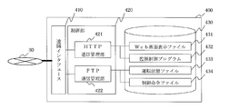
- FIG. 5 is a functional block diagram of the Web server 400.
- the Web server 400 is a server for publishing a home page on the Internet, and includes a remote interface 410, a control unit 420, and a storage unit 430.
- the remote interface 410 communicates with the air conditioning management device 200 and the remote monitoring terminal 500 using HTTP (Hyper Text Transfer Protocol) or FTP (File Transfer Protocol).
- the control unit 420 controls communication using HTTP or FTP.
- the storage unit 430 stores data described later.
- the control unit 420 includes an HTTP communication management unit 421 and an FTP communication management unit 422.
- the HTTP communication management unit 421 transmits a Web screen display file 431 and a monitoring control program 423 described later to the remote monitoring terminal 500 via the remote interface 410.
- the FTP communication management unit 422 transmits and receives an operation state file 433 and a control command file 434 described later between the air conditioning management apparatus 200 and the remote monitoring terminal 500 via the remote interface 410.
- the storage unit 430 stores a Web screen display file 431, a monitoring control program 432, an operation state file 433, and a control command file 434.
- the Web screen display file 431 is data constituting a Web page, such as various HTML files, image files, and sound data displayed on the Web browser provided in the remote monitoring terminal 500.
- the monitoring control program 432 is an application that is executed on the Web browser included in the remote monitoring terminal 500 and that allows the user to monitor and control the air conditioner 100.
- the operation state file 433 is a data file that records the contents of the operation state file that the air conditioning management device 200 transmits to the Web server 400 using FTP.
- the control command file 434 is a data file that records the contents of the control command file that the remote monitoring terminal 500 transmits to the Web server 400 using FTP.
- the control unit 420 and each component included in the control unit 420 can be configured by hardware such as a circuit device that realizes the function, and an arithmetic device such as a microcomputer or a CPU and its operation are defined. It can also consist of software.
- the storage unit 430 can be configured by a storage device such as an HDD or a flash ROM.
- FIG. 6 is a functional block diagram of the remote monitoring terminal 500.
- the remote monitoring terminal 500 is a terminal for a user to connect to the Web server 400 using a Web browser and monitor and control the air conditioner 100.
- the remote monitoring terminal 500 can be configured by a general-purpose personal computer that operates a Web browser.
- the remote monitoring terminal 500 includes a display device 510, an input device 520, a remote interface 530, a control unit 540, and a monitoring control program 550.
- the display device 510 displays a screen for monitoring and controlling the air conditioner 100 generated by the Web browser executed by the control unit 540.
- the input device 520 is a device for a user to input monitoring content switching and control content of the air conditioner 100.
- the remote interface 530 is a communication interface for communicating with the Web server 400 using HTTP or FTP.
- the control unit 540 controls communication using HTTP or FTP.
- a web browser is executed, and a screen for monitoring and controlling the air conditioner 100 is displayed on the display device 510.
- the monitoring control program 550 is executed on the Web browser.
- the monitoring control program 550 includes a program executed on a Web browser such as a Java (registered trademark) applet or Flash, and generates a screen for monitoring and controlling the air conditioner 100 on the Web browser. Details will be described later.
- the control unit 540 includes an HTTP communication management unit 541, an FTP communication management unit 542, a display control unit 543, and a monitoring control program control unit 544.
- the HTTP communication management unit 541 acquires the Web screen display file 431 and the monitoring control program 423 from the Web server 400 via the remote interface 530.
- the control unit 540 expands the acquired monitoring control program 423 on the memory, and executes it on the Web browser as the monitoring control program 550.
- the FTP communication management unit 542 receives the operation state file 433 from the Web server 400 via the remote interface 410 and transmits the control command file 434 to the Web server 400.
- the display control unit 543 controls screen display processing of the Web browser and the monitoring control program 550.
- the supervisory control program control unit 544 performs control such as activation, operation control, and termination management of the supervisory control program 550.
- the monitoring control program 550 is a program executed on the Web browser, and includes an operation data receiving unit 551, a control command data transmitting unit 552, and a display control unit 553. Each of these functional units is configured as one module of a program executed on the Web browser.
- the operation data receiving unit 551 receives and analyzes an operation state file representing the operation state of the air conditioner 100 from the Web server 400.
- the control command data transmission unit 552 transmits a control command file describing a control command for the air conditioner 100 to the Web server 400.
- the display control unit 553 performs screen display processing such as an operation state file.
- the control unit 540 and each component included in the control unit 540 can be configured by hardware such as a circuit device that realizes the function, and an arithmetic device such as a microcomputer or CPU and its operation are defined. It can also be configured with software.
- each device constituting the air conditioning management system has been described above. Next, the operation of each device when remotely monitoring and controlling the air conditioner 100 will be described.
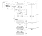
- FIG. 7 is a diagram for explaining the operation procedure of each device for monitoring the operating state of the air conditioner 100 from the remote monitoring terminal 500. Hereinafter, each step of FIG. 7 will be described.
- the control unit 110 of the air conditioner 100 acquires the operation state based on the detection result of the sensor 120 when the operation state of the air conditioner 100 changes or at a timing such as a predetermined time interval, and stores the operation state data 131. Stored in 130.
- the control unit 110 transmits the operation state data 131 to the air conditioning management device 200 via the communication management unit 140 at a timing when the operation state data 131 is created or when a request is received from the air conditioning management device 200.
- S703 The process of the air conditioner 100 ends here.
- the control unit 250 of the air conditioning management device 200 starts an update process of the operation state data 261.
- the facility device communication management unit 251 receives the operation state data transmitted from the air conditioner 100 in step S702 and stores the operation state data in the storage unit 260 as the operation state data 261.
- the control unit 250 acquires a value set in the data update setting 263, and determines whether or not it is time to transmit the operating state data 261 to the Web server 400 and update it. If it is time to update, the process proceeds to step S714. If it is not time to update, the process returns to step S712.
- the operation data transmission unit 255 converts the operation state data 261 into a file format described later with reference to FIG. (S715)
- the operation data transmission unit 255 acquires the value set in the Web server setting 262 and acquires the IP address and the like of the Web server 400.
- the operation data transmission unit 255 transmits the file converted in step S714 to the Web server 400 using FTP via the FTP communication management unit 254 and the remote interface 240.
- the user of the remote monitoring terminal 500 operates the input device 520 to instruct to start the web browser.
- the control unit 540 activates the Web browser and causes the display device 510 to display the screen on the screen.
- the user operates the input device 520 to input the URL (Uniform Resource Locator) of the Web page published by the Web server 400 in the URL field of the Web browser.
- URL Uniform Resource Locator
- the HTTP communication management unit 541 issues an HTTP Web page acquisition request via the remote interface 530 to the URL input by the user in step S721.
- the HTTP communication management unit 541 receives the Web screen display file 431 and the monitoring control program 432 constituting the Web page from the Web server 400.
- the display control unit 543 causes the web browser to display the web screen display file 431 received from the web server 400 in step S722.
- the monitoring control program control unit 544 expands the monitoring control program 432 received from the Web server 400 in step S722 on the memory, and executes it as the monitoring control program 550 on the Web browser.
- the monitoring control program control unit 544 causes the Web browser to display a screen for monitoring and controlling the air conditioner 100 in accordance with the operation defined by the display control unit 553 of the monitoring control program 550.
- the monitoring control program control unit 544 acquires the operation state file 433 by FTP from the Web server 400 via the FTP communication management unit 542 and the remote interface 530 according to the operation specified by the operation data receiving unit 551 of the monitoring control program 550. .
- the monitoring control program control unit 544 analyzes the operation state file 433 received in step S724 in accordance with the operation specified by the operation data receiving unit 551 of the monitoring control program 550.
- the monitoring control program control unit 544 causes the Web browser to display the operation state on the screen according to the operation defined by the display control unit 553.
- the operation state screen display process is terminated.
- the control unit 420 of the Web server 400 waits for a request issued to the Web server 400 using HTTP or FTP.
- the FTP communication management unit 422 receives the operation state file transmitted by the air conditioning management device 200 via the remote interface 410 by FTP.
- the HTTP communication management unit 421 transmits the Web screen display file 431 to the remote monitoring terminal 500 via the remote interface 410.
- the FTP communication management unit 422 transmits the operation state file 433 to the remote monitoring terminal 500 via the remote interface 410.
- FIG. 8 is a diagram illustrating a folder configuration example in the storage unit 430 of the Web server 400.
- the data storage root folder is a top-level folder for storing each data file.
- the data storage root folder is classified by a unique number folder having the same name as the unique number of the air conditioning management device 200.
- the unique number folder stores an HTML file constituting a Web page for instructing the air conditioning management device 200 corresponding to the unique number to monitor and control the air conditioner 100.
- This HTML file constitutes a part of the Web screen display file 431.
- the unique number folder includes an image folder, an operation state file folder, and a control command file folder.
- the image folder stores an image file that constitutes a Web page for instructing the air conditioning management apparatus 200 to monitor and control the air conditioning device 100, other multimedia files, and the like.
- the operation state file folder stores an operation state file 433 corresponding to the air conditioner 100 monitored by the air conditioning management device 200.
- the control command file folder stores a control command file 434 corresponding to the air conditioner 100 controlled by the air conditioning management device 200.
- FIG. 9 is a diagram illustrating a configuration example of the operation state file 433.
- the operation state file 433 is described in CSV (Comma Separated Value) format.
- the first row is the name of each column, and the second and subsequent rows are data rows representing the operating state of the air conditioner 100.
- the first column is the address of the air conditioner 100 monitored by the air conditioning management device 200
- the second column is the power on / off of the air conditioner 100
- the third column is the operation mode
- the fourth column is Current values representing the respective operating states of the set temperature, the fifth column, the intake air temperature, and the sixth column, the fan speed are recorded.
- the file format is not limited to CSV, and may be configured in a file format using blank delimiters or other delimiters, or may be a binary format in which only the data is packed without the delimiters, It may be a file created by compression.
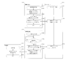
- FIG. 10 is a diagram for explaining the operation procedure of each device for controlling the operation of the air conditioning device 100 from the remote monitoring terminal 500. Hereinafter, each step of FIG. 10 will be described.
- the user of the remote monitoring terminal 500 operates the input device 520 to cause the web browser to display the control screen of the air conditioner 100 on the screen.
- the user operates the input device 520 to input a control command for the air conditioner 100 on the screen of the monitoring control program executed on the Web browser.
- the control command input here is, for example, an operation command such as “turn off power”.
- the monitoring control program control unit 544 of the remote monitoring terminal 500 generates a control command file having a format as described later with reference to FIG. 11 based on the content of the control command input by the user in step S1012.
- the monitoring control program control unit 544 transmits the control command file generated in step S1013 to the Web server 400 by FTP via the FTP communication management unit 542 and the remote interface 530 in accordance with the operation specified by the control command data transmission unit 552. .
- S1015 The operation of the remote monitoring terminal 500 is finished.
- the control unit 250 of the air conditioning management device 200 starts execution processing of the control command.
- the control unit 250 proceeds to the step of executing the following control command at a predetermined time interval, for example. If it is the timing to execute the control command, the process proceeds to the next step S1023.
- the control command file receiving unit 256 receives the control command file 434 from the Web server 400 by FTP via the FTP communication management unit 254 and the remote interface 240. (S1024) The control command file receiving unit 256 analyzes the received control command file 434. The control command file receiving unit 256 executes a control command for the air conditioner 100 that is instructed by the control command file 434 via the facility device communication management unit 251 and the facility device interface 230.
- the control unit 420 of the Web server 400 waits for a request issued to the Web server 400 using HTTP or FTP.
- the FTP communication management unit 422 receives the control command file transmitted from the remote monitoring terminal 500 via the remote interface 410 by FTP.
- the FTP communication management unit 422 transmits a control command file 434 to the air conditioning management device 200 via the remote interface 410.
- the control unit 110 of the air conditioner 100 starts control processing.
- the control unit 110 receives a control command issued by the air conditioning management device 200 via the communication management unit 140 and executes the control operation.
- S1043 The control process ends.
- FIG. 11 is a diagram showing a configuration example of the control command file 434. As shown in FIG. In this example, an example in which operation and schedule setting are performed is shown, but control data such as energy saving control and scheduled communication is also used.
- the file format is not limited to CSV, but may be configured as a file format using blank delimiters or other delimiters, or may be a binary format in which only the data is packed without the delimiters, and the data is compressed. It is also possible to create a file.
- the following (1) to ( A technique such as 2) may be used.
- the storage unit 430 of the Web server 400 stores an air conditioning management device connection setting file that describes which air conditioning management device 200 can be connected.
- the control unit 540 of the remote monitoring terminal 500 acquires the air conditioning management device connection setting file, analyzes the contents, grasps which air conditioning management device 200 can be connected via the Web server 400, and the user connects The air conditioning management device 200 to be selected can be selected.
- the air conditioning management device connection setting file described above may be manually registered in the Web server 400 after the air conditioning management device 200 is installed, or may be automatically registered in the Web server 400 from the air conditioning management device 200. Also good.
- the air conditioning management system since it is not necessary to directly access the air conditioning management device 200 from the remote monitoring terminal 500, there is no need to assign a global (fixed) IP address to the air conditioning management device 200. Thus, it is possible to reduce the cost for acquiring the global IP address.
- the running cost can be reduced.
- the configuration cannot directly access the air conditioning management device 200 in the building from the Internet 30, there is no mischief or attack from a malicious user on the Internet 30, and it is safe in terms of network security. .
- the operating state file is transmitted from the air conditioning management device 200 installed in the LAN 20 to the Web server 400.
- the air conditioning management device 200 installed in the LAN 20 cannot be accessed from the Internet 30 and therefore cannot remotely monitor and control the air conditioning equipment 100.
- the remote monitoring terminal 500 has the above configuration.
- the air conditioner 100 can be monitored and controlled via the Internet 30.
- the air conditioning management system it is possible to switch the monitoring screens of a plurality of air conditioning management devices 200 installed in a building with links within the same Web page, and there is no need to switch URLs. Therefore, the time required for the monitoring operation can be shortened.
- Embodiment 3 the communication between the air conditioning management device 200 and the Web server 400 and the communication between the Web server 400 and the remote monitoring terminal 500 do not take any special measures against information leakage.
- the following (1) to (3) can be considered as methods for preventing information leakage.
- (1) User authentication (1.1) Authentication via Web server 400 An authentication information file describing authentication information for using the air conditioning management device 200 is stored in the storage unit 260 of the air conditioning management device 200. Keep it.
- the user of the remote monitoring terminal 500 uses the input device 520 to input login information (user name, password, etc.).
- the remote monitoring terminal 500 transmits login information to the Web server 400 when accessing the Web server 400.
- the Web server 400 stores the login information in the storage unit 430 as a login information file.
- the control unit 250 of the air conditioning management device 200 acquires the above-described login information file and compares the content with the authentication information file stored in the storage unit 260.
- the control unit 250 transmits the operation state file to the web server 400 and acquires the control command file 434 from the web server 400 only after confirming that both contents match.
- control unit 540 of the remote monitoring terminal 500 acquires the above-mentioned encryption key in advance, and uses the encryption key when transmitting the control command file to the Web server 400. To encrypt the control command file.
- the control unit 250 of the air conditioning management device 200 decrypts the control command file 434 using the encryption key held by itself.
- the control unit 250 of the air-conditioning management apparatus 200 operates when transmitting a file recording the fact of authentication to the Web server 400.
- the decryption key of the state file may be included in this.
- the control unit 250 of the air conditioning management apparatus 200 transmits a file recording the fact that it has been authenticated to the Web server 400, the control unit 250 encrypts the file using login information input to the remote monitoring terminal 500 and transmits the encrypted file. May be.
- the air conditioning management system it is possible to prevent the contents of the operation state file 433 and the control command file 434 from leaking due to authentication and encryption.
- the information leakage countermeasure as in the third embodiment is effective because the packet passes through an unspecified number of communication devices.
- the monitoring control program 550 is described as being a program executed on a Web browser.
- the configuration of the monitoring control program 550 is not limited to this.
- the monitoring control program 550 is configured as a general application capable of storing data. Since the devices other than the remote monitoring terminal 500 and the network configuration are the same as those in the first to third embodiments, description thereof will be omitted.
- FIG. 12 is a functional block diagram of remote monitoring terminal 500 according to the fourth embodiment.
- the remote monitoring terminal 500 newly includes a storage unit 560 in addition to the configuration described in FIG. 6 of the second embodiment.
- the monitoring control program 550 is configured as a general stand-alone application, and additionally includes a data storage unit 554 in addition to the configuration described in FIG. 6 of the second embodiment.
- the function of the component having the same name is the same as that described with reference to FIG.
- Each functional unit included in the monitoring control program 550 is configured as one module of a stand-alone application.
- the data storage unit 554 stores each data file described later in the storage unit 560.
- the storage unit 560 stores an operation state file 561, a data collection setting 562, a monitoring target setting 563, and a display setting unit 564.
- the operation state file 561 is obtained by storing the operation state file 433 acquired from the Web server 400 in the storage unit 560.
- the data collection setting 562 is a data file that records items to be collected and the cycle of the operating state of the air conditioner 100 to be monitored.
- the remote monitoring terminal 500 transmits this content to the air conditioning management device 200 when performing remote monitoring. This eliminates the need to update the software of the air-conditioning management apparatus 200 in order to update the items to be collected and their cycles when the model of the air-conditioning apparatus 100 is changed or a new model is released. Therefore, it is not necessary to go to the installation location to update the software of the air-conditioning management apparatus 200, and the maintenance work is improved.
- the monitoring target setting 563 is a data file in which setting information indicating which model of the air conditioner 100 is to be collected is collected. If the operation load of all models is collected and the communication load becomes excessive, it is possible to limit the models to be monitored in this setting file and suppress traffic.
- the display setting 564 is a data file that records various settings related to the display method.
- the storage unit 560 can be configured by a storage device such as an HDD or a flash ROM.
- the example in which the remote monitoring terminal 500 issues a control command to the air conditioner 100 has been described.
- the operation defined by the monitoring control program 550 according to the fourth embodiment is basically the same as that described in the second to third embodiments.
- the fourth embodiment as one example of operation, the operation of each device when the remote monitoring terminal 500 instructs the air conditioning management device 200 to periodically acquire the operating state of the air conditioning device 100 is described. explain.
- FIG. 13 is a diagram for explaining an operation procedure of each device when the remote monitoring terminal 500 instructs the air conditioning management device 200 to periodically acquire the operating state of the air conditioning device 100. Hereinafter, each step of FIG. 13 will be described.
- the user of the remote monitoring terminal 500 operates the input device 520 and instructs the monitoring control program 550 to open a screen for inputting an instruction to the air conditioning management device 200.
- the monitoring control program control unit 544 causes the display device 510 to display a screen for inputting an instruction to the air conditioning management device 200 in accordance with the operation defined by the display control unit 553.
- the user operates the input device 520 and inputs a unit, an item, a collection cycle, a collection period, and the like for collecting operation states.
- the monitoring control program control unit 544 stores the input content in the storage unit 560 as the data collection setting 562 and the monitoring target setting 563 in accordance with the operation specified by the data storage unit 554. (S1313) to (S1315) Since this is the same as steps S1013 to S1015 in FIG.
- the control command file receiving unit 256 of the air conditioning management device 200 analyzes the received control command file 434.
- the control command file 434 an instruction to periodically acquire the operating state of the air conditioner 100 is described for the air conditioning management device 200.
- the control unit 250 updates the data update setting 263 based on the instruction content. (S1325) The control instruction execution process is terminated.
- the control unit 250 starts a scheduled communication process based on the setting contents of the data update setting 263.
- the control unit 250 determines whether it is the timing of scheduled communication based on the setting contents of the data update setting 263. If it is the scheduled communication timing, the process proceeds to step S1328, and if it is not the scheduled communication timing, this step is re-executed by waiting for a predetermined time.
- the control unit 250 executes a control command for acquiring operating state data of the air conditioner 100 via the facility device communication management unit 251 and the facility device interface 230.
- the facility device communication management unit 251 receives the operation state data transmitted from the air conditioner 100 and stores the operation state data as the operation state data 261 in the storage unit 260.
- FIG. 14 is a diagram for explaining the operation procedure of each device for monitoring the operating state of the air conditioning device 100 from the remote monitoring terminal 500. Hereinafter, each step of FIG. 14 will be described.
- the user of the remote monitoring terminal 500 operates the input device 520 to instruct to start the monitoring control program 550.
- the supervisory control program control unit 544 activates the supervisory control program 550 and displays the screen on the display device 510.
- the user operates the input device 520 to display a screen for monitoring / controlling the air conditioner 100 on the monitor control program 550.
- the monitoring control program control unit 544 acquires the operation state file 433 by FTP from the Web server 400 via the FTP communication management unit 542 and the remote interface 530 in accordance with the operation specified by the operation data receiving unit 551 of the monitoring control program 550. . (S1423) The monitoring control program control unit 544 analyzes the operation state file 433 received in step S1422 according to the operation specified by the operation data receiving unit 551 of the monitoring control program 550.
- the supervisory control program control unit 544 displays the contents of the operation state file 433 in a graph according to the operations defined by the display control unit 553 and the data storage unit 554, accumulates the contents in the storage unit 560, and transmits the contents by e-mail.
- the operation unique to the monitoring control program 550 is executed. Such an operation may be difficult to perform with a program executed on a Web browser, but can be easily performed with a stand-alone application. (S1425) The operation of the monitoring control program 550 is terminated.
- the remote monitoring terminal 500 is configured using a general-purpose computer.
- a mobile phone, a PDA (Personal Digital Assistant), a mobile computer, or the like can be used instead.
- transmission / reception of the operation state file between the remote monitoring device 500 and the air conditioning management device 200 installed in a remote place is performed via the Web server 400. By doing so, it is possible to check the operation status file collected periodically without going to the site at a remote location.
- the remote monitoring terminal 500 is not so limited in installation space and main body size, and can be configured using a general-purpose computer, so that it can have a relatively large storage area. Therefore, a large-capacity operating state file can be stored in the storage unit 560, and pressure, temperature, compressor rotation speed, capacity saving amount, etc. that could not be collected due to memory size limitations of the air conditioning management device 200 conventionally. It is possible to collect a large amount of operation state data.
- Embodiment 5 FIG.
- the Web server 400 is connected to the Internet 30.
- a dedicated server in order to install such a dedicated server, specialized knowledge is required.
- the operation management of the server requires a cost. Therefore, in the fifth embodiment of the present invention, an example will be described in which a web server that is generally available free of charge is used as the web server 400 described in the first to fourth embodiments. Note that the configuration of each device and network is the same as in Embodiments 1 to 4, and a description thereof will be omitted.
- the designer of the air conditioning management system makes a contract with an Internet connection provider in order to prepare an Internet connection environment.
- various settings for Internet connection are set in the Internet connection router 600, and the air conditioning management device 200 connected to the LAN 20 can communicate with the server on the Internet 30. Like that.
- the designer of the air-conditioning management system sets the server name or IP address of the Web server 400 provided as a homepage service by the Internet service provider in the Web server setting 262 in the storage unit 260.
- the data update setting 263 a time interval for updating the operation state data to the Web server 400 and a time interval for reading the control contents from the Web server 400 are set.
- the setting content may be input from the input device 220 of the air conditioning management device 200 or may be set from the local monitoring terminal 300 or the remote monitoring terminal 500.
- the Web server provided by the Internet connection provider transmits and receives operation data between the remote monitoring terminal 500 and the air conditioning management device 200 installed in a remote place.
- the Web server By performing via 400, there is no need to install a Web server on the Internet. This eliminates the load of Web server startup and regular maintenance (including security measures) and data backup that have been performed in the past, so even users without specialized knowledge about Web servers can easily build an air conditioning management system. Is possible.
- the Web server function (homepage service) provided by the Internet connection provider is a service that is generally provided free of charge when making an Internet connection contract. It is possible to reduce the introduction cost and the running cost when constructing the air conditioning management system.
- Embodiment 6 FIG. In the sixth embodiment of the present invention, modifications of the first to fifth embodiments will be described. Since the configuration other than the matters described in the sixth embodiment is the same as in the first to fifth embodiments, the description will focus on the differences.
- Programs such as CGI (Common Gateway Interface) and Servlet for accepting file transmission are installed in the Web server 400.
- the air conditioning management device 200 or the remote monitoring terminal 500 issues an HTTP POST request to this program, and transmits the contents of the target file to the program.
- the air conditioning management device 200 or the remote monitoring terminal 500 acquires a file from the Web server 400, the file may be placed in a folder under the HTTP server and an HTTP GET request may be issued for the file.
- the Web server 400 receives predetermined log-in information from the air conditioning management device 200 or the remote monitoring terminal 500 via a program such as CGI, and only when it is legitimate, the Web server 400 retrieves the target file via the CGI.
- a method of transmitting is also conceivable.
- the Web server 400 opens an appropriate TCP port and waits for a request from the air conditioning management device 200 or the remote monitoring terminal 500.
- the air conditioning management device 200 and the remote monitoring terminal 500 issue a file transmission / reception request to the TCP port when transmitting / receiving a file to / from the Web server 400.
- the network configuration is such that the LAN 20 connected to the air conditioning management device 200 is connected to the Internet 30 via the Internet connection router 600.
- a proxy server generally used when connecting to the Internet 30 from a LAN is installed in the building of FIG. 1 or in a remote place, and the air conditioning management device 200 or the remote monitoring terminal 500 is connected to the Web server 400.
- it is good also as a structure connected through a proxy server.
- the air conditioning management apparatus 200 accesses the Web server 400 at the timing set in the data update setting 263.
- the data update setting 263 is described. You may make it operate
- the Web server 400 may be accessed at a timing when a specific event occurs, such as when operating state data is received from the air conditioner 100.
- the dedicated communication line 10 connecting the air conditioning management device 200 and the air conditioning equipment 100 may use a communication line unique to the air conditioning equipment 100, or may use a general-purpose communication line such as a LAN. .
- the local monitoring terminal 300 is included in the system configuration for monitoring in the building, it is not always necessary to install the local monitoring terminal 300 if it is a system only for monitoring and control from a remote location.
Landscapes
- Engineering & Computer Science (AREA)
- Chemical & Material Sciences (AREA)
- Combustion & Propulsion (AREA)
- Mechanical Engineering (AREA)
- General Engineering & Computer Science (AREA)
- Human Computer Interaction (AREA)
- Physics & Mathematics (AREA)
- Fuzzy Systems (AREA)
- Mathematical Physics (AREA)
- Signal Processing (AREA)
- Air Conditioning Control Device (AREA)
Abstract
Description
また、遠隔操作盤1台につき1個のグローバルIPアドレス(インターネット上で固有のIPアドレス)を利用する必要があり、ランニングコストがかかる。
したがって、インターネット上の悪意のあるユーザからのいたずらや攻撃を受けることが無く、情報セキュリティの観点から安全である。
図1は、本発明の実施の形態1に係る空調管理システムの構成図である。
本実施の形態1に係る空調管理システムは、一つ以上の建物を持つ施設内に、空調機器100a~100b、空調管理装置200a~200c、ローカル監視端末300を有する。また、インターネット30を介してWebサーバ400が接続され、遠隔地には同様にインターネット30に接続された遠隔監視端末500を有する。
空調管理装置200a~200c、ローカル監視端末300は、LAN20を介して互いに接続され、通信によりデータを送受信することができる。また、LAN20は、インターネット接続用ルータ600を介してインターネット30に接続されている。
空調管理装置200は、複数の空調機器100を統合的に監視、制御する装置である。
ローカル監視端末300は、Webブラウザが動作する汎用パソコンで構成される。ユーザは、ローカル監視端末300のWebブラウザ上で、空調機器の運転状態、異常情報、各種運転データの監視や設定を行うことができる。
遠隔監視端末500は、Webブラウザが動作する汎用パソコンで構成することができる。ユーザは、遠隔監視端末500のWebブラウザを用いてインターネット30に接続し、空調機器100の監視、制御を行う。具体的な手法は後述する。
インターネット接続用ルータ600は、配下のLAN20からインターネット30に向けたパケットを中継する際に、NAT(Network Address Translation)を実行する。
これにより、LAN20に接続される各機器は、インターネット接続用ルータ600を介してインターネット30に接続することができる。
一方、インターネット30の側からは、インターネット接続用ルータ600配下のLAN20に接続することはできない。
そこで、本実施の形態1に係る空調管理システムでは、遠隔監視端末500から空調機器100の監視、制御を行うため、次の図2で説明するような手法を用いる。
(a.1)空調管理装置200は、空調機器100の運転状態を定期的に取得する。なお、空調機器100の運転状態が変化した際に、空調機器100より空調管理装置200に自動的にその内容を通知するようにしてもよい。
(a.2)空調管理装置200は、空調機器100の運転状態を、運転状態ファイルとしてWebサーバ400に送信する。定期的に送信するようにしてもよいし、空調機器100の運転状態が変化したときのみ送信してもよい。Webサーバ400は、その運転状態ファイルを記憶手段に格納する。
(a.3)ユーザは、遠隔監視端末500のWebブラウザを用いてWebサーバ400にアクセスし、上述の運転状態ファイルの送信を要求する。ユーザは、取得した運転状態ファイルをWebブラウザ上で閲覧することで、空調機器100の運転状態を監視する。
(b.1)ユーザは、遠隔監視端末500のWebブラウザを用いて、空調機器100に対する制御命令を入力する。遠隔監視端末500は、その入力に基づき制御命令ファイルを生成し、Webサーバ400に送信する。Webサーバ400は、その制御命令ファイルを記憶手段に格納する。
(b.2)空調管理装置200は、Webサーバ400が格納している上述の制御命令ファイルを送信するよう、Webサーバ400へ定期的に要求する。
(b.3)空調管理装置200は、取得した制御命令ファイル中で指示されている制御命令を実行し、空調機器100の制御を行う。
例えば、空調機器100に対する操作でもよいし、空調管理装置200に対するスケジュールや省エネなどの設定でもよく、空調管理装置200に対し空調機器100の運転状態を定期的に取得するよう指示するものでもよい。
これにより、LAN20に接続された空調機器100や空調管理装置200をインターネット30から直接アクセスできるようにするネットワーク構成と比較して、これらの機器のネットワークセキュリティを高めることができる。
これにより、遠隔監視端末500は、LAN20に直接アクセスすることなく、空調機器100の運転状態を監視することができるので、LAN20に接続された各機器のネットワークセキュリティを維持しつつ、空調機器100に対する遠隔監視を実現することができる。
これにより、遠隔監視端末500は、LAN20に直接アクセスすることなく、空調機器100の制御を行うことができるので、LAN20に接続された各機器のネットワークセキュリティを維持しつつ、空調機器100に対する遠隔制御を実現することができる。
実施の形態1では、本発明に係る空調管理システムのネットワーク構成と、遠隔監視および制御の手法について説明した。
本発明の実施の形態2では、空調管理システムを構成する各機器の詳細構成および動作について、1例を説明する。
空調機器100は、制御部110、センサ120、記憶部130、通信管理部140を備える。
制御部110は、空調機器100の通常動作の制御を行うとともに、センサ120の検出結果を反映して運転状態を制御する。また、センサ120の検出結果を用いて、空調機器100の運転状態を表す運転状態データ131を作成し、記憶部130に格納する。
運転状態データ131の作成は、運転状態が変化した際や、所定時間間隔など、適宜定められたタイミングで実行する。
センサ120は、空調機器100の各部の温度や圧力などを検出する。
記憶部130は、運転状態データ131と、空調機器100の機種情報132とを格納する。機種情報132は、あらかじめ記憶部130に格納しておいてもよいし、ユーザが入力するなどして設定してもよい。
通信管理部140は、空調管理装置200と通信を行う。
記憶部130は、HDDやフラッシュROM(Read Only Memory)のような記憶装置で構成することができる。
通信管理部140は、空調管理装置200と接続するために必要な通信インターフェースを備える。
空調管理装置200は、一つ以上の建物を持つ施設に配備された空調機器100を統合的に監視、制御する装置であり、表示装置210、入力装置220、設備機器インタフェース230、遠隔インタフェース240、制御部250、記憶部260を備える。
入力装置220は、ユーザが監視画面切り換えや空調機器100の操作入力を行うための装置である。
設備機器インタフェース230は、空調機器100と接続して通信を行うための通信インタフェースである。
遠隔インタフェース240は、LAN20に接続され、ローカル監視端末300やWebサーバ400と通信を行うための通信インタフェースである。
制御部250は、通常動作用の画面表示や入力受付、空調機器100の運転制御を行う。また、空調機器100、ローカル監視端末300、Webサーバ400との通信制御を行う。
記憶部260は、後述の各データを格納する。
設備機器通信管理部251は、設備機器インタフェース230を介して空調機器100と通信し、空調機器100の動作を制御し、また、運転状態データを取得して記憶部260に格納する。
ローカル通信管理部252は、遠隔インタフェース240を介して、同一建物内に設置されたローカル管理端末300との通信を行う。
遠隔通信管理部253は、Webサーバ400への運転状態データの送信、制御命令ファイルの受信・解析を行う。
FTP通信管理部254は、Webサーバ400との間のFTP通信制御を行う。
運転データ送信部255は、空調機器100から取得した運転状態データ261を、FTP通信管理部254を介してWebサーバ400に定期的に送信する。
制御命令ファイル受信部256は、空調機器100に対する制御命令を記載した制御命令ファイルを、FTP通信管理部254を介してWebサーバ400から受信し、その内容を解析する。
運転状態データ261は、空調機器100の運転状態を表すデータである。
Webサーバ設定262は、Webサーバ400のIPアドレスやURL等が記録されたデータファイルである。
データ更新設定263は、各データの収集項目や収集周期、Webサーバ400へ運転状態データ261を送信するタイミング等の更新設定を記録したデータファイルである。
製造番号264は、空調管理装置200の固有製造番号を記録したデータファイルである。製造番号以外の固有番号、例えばMACアドレスやシリアルナンバーを用いてもよい。
Webサーバ設定262、データ更新設定263、製造番号264は、あらかじめ記憶部260に格納しておいてもよいし、ユーザが入力するなどして設定してもよい。
記憶部260は、HDDやフラッシュROMのような記憶装置で構成することができる。
Webサーバ400は、インターネット上にホームページを公開するためのサーバであり、遠隔インタフェース410、制御部420、記憶部430を備える。
制御部420は、HTTPやFTPを用いた通信を制御する。
記憶部430は、後述の各データを格納する。
HTTP通信管理部421は、遠隔インタフェース410を介して、遠隔監視端末500に対し後述のWeb画面表示ファイル431、監視制御プログラム423を送信する。
FTP通信管理部422は、遠隔インタフェース410を介して、空調管理装置200および遠隔監視端末500との間で、後述の運転状態ファイル433と制御命令ファイル434を送受信する。
Web画面表示ファイル431は、遠隔監視端末500が備えるWebブラウザ上で表示する各種HTMLファイル、画像ファイル、音データ等の、Webページを構成する各データである。
監視制御プログラム432は、遠隔監視端末500が備えるWebブラウザ上で実行され、ユーザが空調機器100の監視や制御を行うためのアプリケーションである。
運転状態ファイル433は、空調管理装置200がWebサーバ400に対しFTPを用いて送信する運転状態ファイルの内容を記録したデータファイルである。
制御命令ファイル434は、遠隔監視端末500がWebサーバ400に対しFTPを用いて送信する制御命令ファイルの内容を記録したデータファイルである。
なお、記憶部430内の具体的なフォルダ構成例は、後述の図8で説明する。
記憶部430は、HDDやフラッシュROMのような記憶装置で構成することができる。
遠隔監視端末500は、ユーザがWebブラウザを用いてWebサーバ400に接続し、空調機器100の監視、制御を行うための端末である。遠隔監視端末500は、Webブラウザが動作する汎用パソコンで構成することができる。
遠隔監視端末500は、表示装置510、入力装置520、遠隔インタフェース530、制御部540、監視制御プログラム550を備える。
入力装置520は、ユーザが空調機器100の監視内容の切り換えや制御内容を入力するための装置である。
遠隔インタフェース530は、HTTPやFTPを用いて、Webサーバ400と通信するための通信インタフェースである。
制御部540は、HTTPやFTPを用いた通信を制御する。また、Webブラウザを実行し、空調機器100を監視・制御するための画面を表示装置510に画面表示させる。さらには、Webブラウザ上で、監視制御プログラム550を実行する。
監視制御プログラム550は、例えばJava(登録商標)アプレットやFlashなどのWebブラウザ上で実行されるプログラムで構成され、Webブラウザ上で、空調機器100を監視・制御するための画面を生成する。詳細は後述する。
FTP通信管理部542は、遠隔インタフェース410を介して、Webサーバ400より運転状態ファイル433を受信し、Webサーバ400へ制御命令ファイル434を送信する。
表示制御部543は、Webブラウザや監視制御プログラム550の画面表示処理を制御する。
監視制御プログラム制御部544は、監視制御プログラム550の起動、動作制御、終了管理等の制御を行う。
運転データ受信部551は、Webサーバ400から、空調機器100の運転状態を表す運転状態ファイルを受信して解析する。
制御命令データ送信部552は、Webサーバ400に、空調機器100に対する制御命令を記載した制御命令ファイルを送信する。
表示制御部553は、運転状態ファイル等の画面表示処理を行う。
次に、空調機器100を遠隔から監視・制御する際の各機器の動作を説明する。
空調機器100の制御部110は、空調機器100の運転状態が変化した際、または所定時間間隔などのタイミングで、センサ120の検出結果等に基づき運転状態を取得し、運転状態データ131を記憶部130に格納する。
(S702)
制御部110は、運転状態データ131を作成したタイミング、または空調管理装置200から要求を受けたタイミングなどで、空調管理装置200に対し、通信管理部140を介して運転状態データ131を送信する。
(S703)
空調機器100の処理は、以上で終了する。
空調管理装置200の制御部250は、運転状態データ261の更新処理を開始する。
(S712)
設備機器通信管理部251は、ステップS702で空調機器100が送信した運転状態データを受信し、記憶部260に運転状態データ261として格納する。
(S713)
制御部250は、データ更新設定263に設定されている値を取得し、運転状態データ261をWebサーバ400に送信して更新するタイミングであるか否かを判定する。
更新するタイミングであればステップS714へ進み、更新するタイミングでなければステップS712に戻る。
運転データ送信部255は、運転状態データ261を、後述の図9で説明するファイル形式に変換する。
(S715)
運転データ送信部255は、Webサーバ設定262に設定されている値を取得し、Webサーバ400のIPアドレス等を取得する。次に、運転データ送信部255は、ステップS714で変換したファイルを、FTP通信管理部254および遠隔インタフェース240を介して、Webサーバ400にFTPを用いて送信する。
遠隔監視端末500のユーザは、入力装置520を操作して、Webブラウザを起動するよう指示する。制御部540は、Webブラウザを起動し、その画面を表示装置510に画面表示させる。
次にユーザは、入力装置520を操作して、WebブラウザのURL欄に、Webサーバ400が公開しているWebページのURL(Uniform Resource Locator)を入力する。
HTTP通信管理部541は、ステップS721でユーザが入力したURLに対し、遠隔インタフェース530を介して、HTTPのWebページ取得要求を発行する。
HTTP通信管理部541は、そのWebページを構成するWeb画面表示ファイル431と監視制御プログラム432を、Webサーバ400より受信する。
表示制御部543は、ステップS722でWebサーバ400から受信したWeb画面表示ファイル431を、Webブラウザに画面表示させる。
監視制御プログラム制御部544は、ステップS722でWebサーバ400から受信した監視制御プログラム432をメモリ上に展開し、監視制御プログラム550として、Webブラウザ上で実行する。
次に、監視制御プログラム制御部544は、監視制御プログラム550の表示制御部553が規定する動作に従い、空調機器100の監視・制御を行うための画面を、Webブラウザに画面表示させる。
監視制御プログラム制御部544は、監視制御プログラム550の運転データ受信部551が規定する動作に従い、FTP通信管理部542、遠隔インタフェース530を介して、Webサーバ400より運転状態ファイル433をFTPで取得する。
(S725)
監視制御プログラム制御部544は、監視制御プログラム550の運転データ受信部551が規定する動作に従い、ステップS724で受信した運転状態ファイル433を解析する。
次に、監視制御プログラム制御部544は、表示制御部553が規定する動作に従い、その運転状態をWebブラウザに画面表示させる。
(S726)
運転状態の画面表示処理を終了する。
Webサーバ400の制御部420は、HTTPやFTPを用いてWebサーバ400宛てに発行されるリクエストを待機している。
(S732)
FTP通信管理部422は、遠隔インタフェース410を介して、空調管理装置200が送信した運転状態ファイルをFTPで受信する。
(S733)
HTTP通信管理部421は、遠隔インタフェース410を介して、遠隔監視端末500にWeb画面表示ファイル431を送信する。
(S734)
FTP通信管理部422は、遠隔インタフェース410を介して、遠隔監視端末500に運転状態ファイル433を送信する。
データ格納用ルートフォルダは、各データファイルを配下に格納するための最上位フォルダである。
データ格納用ルートフォルダは、空調管理装置200の固有番号と同一の名称が付された固有番号フォルダで区分けされている。
固有番号フォルダは、その固有番号に対応する空調管理装置200に対し空調機器100の監視・制御を指示するためのWebページを構成するHTMLファイルを格納している。本HTMLファイルは、Web画面表示ファイル431の一部を構成する。
また、固有番号フォルダは、画像フォルダ、運転状態ファイルフォルダ、制御命令ファイルフォルダを有する。
運転状態ファイルフォルダは、当該空調管理装置200が監視を行う空調機器100に対応した運転状態ファイル433を格納する。
制御命令ファイルフォルダは、当該空調管理装置200が制御を行う空調機器100に対応した制御命令ファイル434を格納する。
運転状態ファイル433はCSV(Comma Separated Value)形式で記載されている。1行目は各列の名称、2行目以降が空調機器100の運転状態を表すデータ行である。
また、ファイル形式はCSVに限らず、空白区切りやその他の区切り文字を使ったファイル形式で構成してもよいし、区切り文字を無くしてデータのみを詰めたバイナリ形式としてもよく、さらにはデータを圧縮して作成したファイルとしてもよい。
次に、遠隔監視端末500から空調機器100の動作を制御するための、各機器の動作手順を説明する。
遠隔監視端末500のユーザは、入力装置520を操作して、Webブラウザに空調機器100の制御画面を画面表示させる。
(S1012)
ユーザは、入力装置520を操作して、Webブラウザ上で実行されている監視制御プログラムの画面上で、空調機器100に対する制御命令を入力する。ここで入力される制御命令は、例えば「電源をOFFにする」といった動作指令である。
遠隔監視端末500の監視制御プログラム制御部544は、ステップS1012でユーザが入力した制御命令の内容に基づき、後述の図11で説明するような形式の制御命令ファイルを生成する。
(S1014)
監視制御プログラム制御部544は、制御命令データ送信部552が規定する動作に従い、FTP通信管理部542、遠隔インタフェース530を介して、ステップS1013で生成した制御命令ファイルをFTPでWebサーバ400に送信する。
(S1015)
遠隔監視端末500の動作を終了する。
空調管理装置200の制御部250は、制御命令の実行処理を開始する。
(S1022)
制御部250は、例えば所定時間間隔などで、以下の制御命令を実行するステップに進む。制御命令を実行するタイミングであれば次のステップS1023へ進み、実行するタイミングでなければ例えば所定時間待機して本ステップを再実行する。
制御命令ファイル受信部256は、FTP通信管理部254、遠隔インタフェース240を介して、Webサーバ400より制御命令ファイル434をFTPで受信する。
(S1024)
制御命令ファイル受信部256は、受信した制御命令ファイル434を解析する。
制御命令ファイル受信部256は、設備機器通信管理部251、設備機器インタフェース230を介して、制御命令ファイル434で指示されている、空調機器100に対する制御命令を実行する。
Webサーバ400の制御部420は、HTTPやFTPを用いてWebサーバ400宛てに発行されるリクエストを待機している。
(S1032)
FTP通信管理部422は、遠隔インタフェース410を介して、遠隔監視端末500が送信した制御命令ファイルをFTPで受信する。
(S1033)
FTP通信管理部422は、遠隔インタフェース410を介して、空調管理装置200に制御命令ファイル434を送信する。
空調機器100の制御部110は、制御処理を開始する。
(S1042)
制御部110は、通信管理部140を介して空調管理装置200が発行した制御命令を受け取り、その制御動作を実行する。
(S1043)
制御処理を終了する。
この例では、操作とスケジュール設定を行う例を示したが、省エネ制御や定時通信等の制御データも利用される。
制御命令ファイル434は、CSV形式のテキストファイルである。各列は、「制御対象項目=制御値」の形式で記載されている。
ファイル形式はCSVに限らず、空白区切りやその他の区切り文字を使ったファイル形式で構成してもよいし、区切り文字を無くしてデータのみを詰めたバイナリ形式としてもよく、さらにはデータを圧縮して作成したファイルとしてもよい。
遠隔監視端末500の制御部540は、空調管理装置接続設定ファイルを取得して内容を解析し、Webサーバ400を介してどの空調管理装置200と接続することができるかを把握し、ユーザが接続する空調管理装置200を選択できるようにする。
上述の空調管理装置接続設定ファイルは、空調管理装置200を設置した後にWebサーバ400へ手動で登録するようにしてもよいし、空調管理装置200からWebサーバ400へ自動的に登録するようにしてもよい。
ユーザは、Webブラウザ上でそのリンクをクリックすると、該当する運転状態ファイルフォルダに格納されている運転状態ファイル433を閲覧することができる。
従来の技術ではLAN20内に設置された空調管理装置200はインターネット30からアクセスすることができないため、空調機器100を遠隔監視・制御することができなかったが、上記の構成により、遠隔監視端末500からインターネット30を介して空調機器100の監視、制御が可能となる。
実施の形態1~2では、空調管理装置200~Webサーバ400間の通信や、Webサーバ400~遠隔監視端末500間の通信は、特段の情報漏洩対策を施していない。また、運転状態ファイル433や制御命令ファイル434についても同様である。
そこで、本発明の実施の形態3では、これらのデータファイルや通信経路を暗号化するなどして情報漏洩対策を施す例を説明する。なお、各機器およびネットワークの構成は、実施の形態1~2と同様であるため、説明を省略する。
(1.1)Webサーバ400を介した認証
空調管理装置200の記憶部260に、当該空調管理装置200を利用するための認証情報を記載した認証情報ファイルを格納しておく。
遠隔監視端末500のユーザは、入力装置520を用いて、ログイン情報(ユーザー名、パスワード等)を入力する。
遠隔監視端末500は、Webサーバ400にアクセスする際に、ログイン情報をWebサーバ400に送信する。Webサーバ400は、記憶部430にそのログイン情報をログイン情報ファイルとして格納する。
空調管理装置200の制御部250は、Webサーバ400と通信する際に、上述のログイン情報ファイルを取得し、記憶部260に格納されている認証情報ファイルと内容を比較する。
制御部250は、両者の内容が合致することを確認した後に限り、Webサーバ400に運転状態ファイルを送信し、Webサーバ400より制御命令ファイル434を取得する。
上記(1.1)に記載の手順において、空調管理装置200の制御部250は、ログイン情報ファイルと認証情報ファイルの内容が合致することを確認した後に、Webサーバ400に運転状態ファイルを送信するとともに、認証済みの旨を記録したファイルを送信する。
遠隔監視端末500は、Webサーバ400にアクセスし、上述の認証済みの旨を記録したファイルがWebサーバ400に格納されている場合に限り、Webサーバ400より運転状態ファイルを取得する。
(2.1)運転状態ファイル433の暗号化
空調管理装置200の制御部250は、Webサーバ400に運転状態ファイルを送信する際に、例えば製造番号264など当該空調管理装置200に固有の値を用いて生成した暗号鍵を用いて、運転状態ファイルを暗号化しておく。
遠隔監視端末500の制御部540は、あらかじめその暗号鍵を取得しておき、Webサーバ400より運転状態ファイル433を取得した際に、その暗号鍵を用いて運転状態ファイル433を復号化する。
遠隔監視端末500の制御部540は、あらかじめ上述の暗号鍵を取得しておき、Webサーバ400に制御命令ファイルを送信する際に、その暗号鍵を用いて制御命令ファイルを暗号化しておく。
空調管理装置200の制御部250は、Webサーバ400より制御命令ファイル434を取得した際に、自己が保持する暗号鍵を用いて、制御命令ファイル434を復号化する。
空調管理装置200の制御部250は、Webサーバ400に運転状態ファイルを送信する際に、上述の(1)で説明した認証情報を用いて、運転状態ファイルを暗号化しておく。
遠隔監視端末500の制御部540は、Webサーバ400より運転状態ファイル433を取得した際に、ログイン情報を用いて復号鍵を生成し、運転状態ファイル433を復号化する。
空調管理装置200が保持している認証情報と、遠隔監視端末500に入力されたログイン情報とが合致しているのであれば、暗号鍵と復号鍵が対応付けられていることになる。したがって、遠隔監視端末500の制御部540は、運転状態ファイル433を復号化することができる。
制御命令ファイル434の送信に関しても、同様にログイン情報を用いて暗号化を行うことができる。
上記(1.2)に記載の手順において、空調管理装置200の制御部250は、Webサーバ400に認証済みの旨を記録したファイルを送信する際に、運転状態ファイルの復号鍵をこれに含めておいてもよい。
また、空調管理装置200の制御部250は、認証済みの旨を記録したファイルをWebサーバ400に送信する際に、遠隔監視端末500に入力されたログイン情報等を用いて暗号化した上で送信してもよい。
運転状態ファイルの復号鍵を生成する際には、例えばログイン情報ファイルに日時情報等を加えた値を用い、一意の復号鍵となるように留意してもよい。
これにより、過去に生成された復号鍵が不正に取得された場合でも、その復号鍵を用いて運転状態ファイルを復号することはできなくなり、安全性が高まる。
空調管理装置200~Webサーバ400間の通信や、Webサーバ400~遠隔監視端末500間の通信は、SSL(Secure Sockets Layer)などを用いて暗号化、認証を行うようにしてもよい。
また、SSLで用いられる証明書データを元に、運転状態ファイル433、制御命令ファイル434の暗号化を行ってもよい。
暗号化や認証の処理は、各機器が備える制御部が実行する。
特に、インターネット30を介して各機器が通信を行うネットワーク構成においては、パケットが不特定多数の通信機器を経由するため、本実施の形態3のような情報漏洩対策が有効である。
実施の形態2~3では、監視制御プログラム550はWebブラウザ上で実行されるプログラムであるものとして説明したが、監視制御プログラム550の構成は、これに限られるものではない。
本発明の実施の形態4では、監視制御プログラム550を、データ保存が可能な一般のアプリケーションとして構成した例を説明する。なお、遠隔監視端末500以外の機器とネットワーク構成は、実施の形態1~3と同様であるため、説明を省略する。
図12において、遠隔監視端末500は、実施の形態2の図6で説明した構成に加えて新たに記憶部560を備える。
また、監視制御プログラム550は、一般のスタンドアロンアプリケーションとして構成されており、実施の形態2の図6で説明した構成に加えて、新たにデータ保存部554を備える。同名の構成部の機能は、図6で説明したものと同様であるため、説明を省略する。
なお、監視制御プログラム550が備える各機能部は、スタンドアロンアプリケーションの1モジュールとして構成されている。
記憶部560は、運転状態ファイル561、データ収集設定562、監視対象設定563、表示設定部564を格納する。
これにより、空調機器100の機種が変更になったり、新しい機種が発売されたりした際にも、収集すべき項目とその周期を更新するために空調管理装置200のソフトウェアを更新する必要がなくなる。
したがって、空調管理装置200のソフトウェアを更新するために設置場所に出向いてバージョンアップ作業等を行う必要がなく、メンテナンス性が向上する。
表示設定564は、表示方法に関する各種設定を記録したデータファイルである。
本実施の形態4では、動作例の1つとして、遠隔監視端末500から空調管理装置200に対し、定期的に空調機器100の運転状態を取得すべき旨を指示する際の各機器の動作を説明する。
遠隔監視端末500のユーザは、入力装置520を操作し、監視制御プログラム550上で、空調管理装置200に対する指示を入力するための画面を開くよう指示する。
監視制御プログラム制御部544は、表示制御部553が規定する動作に従い、空調管理装置200に対する指示を入力するための画面を表示装置510に画面表示させる。
(S1312)
ユーザは、入力装置520を操作し、運転状態を収集するユニット、項目、収集周期、収集期間等を入力する。
監視制御プログラム制御部544は、データ保存部554が規定する動作に従い、入力内容をデータ収集設定562と監視対象設定563として、記憶部560に格納する。
(S1313)~(S1315)
図10のステップS1013~S1015と同様であるため、説明を省略する。
図10のステップS1021~S1023と同様であるため、説明を省略する。
(S1324)
空調管理装置200の制御命令ファイル受信部256は、受信した制御命令ファイル434を解析する。制御命令ファイル434には、当該空調管理装置200に対し、空調機器100の運転状態を定期的に取得すべき旨の指示が記載されている。
制御部250は、その指示内容に基づき、データ更新設定263を更新する。
(S1325)
制御命令実行処理を終了する。
制御部250は、データ更新設定263の設定内容に基づく定時通信処理を開始する。
(S1327)
制御部250は、データ更新設定263の設定内容に基づく定時通信のタイミングであるか否かを判定する。定時通信タイミングであればステップS1328へ進み、定時通信タイミングでなければ所定時間待機するなどして本ステップを再実行する。
制御部250は、設備機器通信管理部251、設備機器インタフェース230を介して、空調機器100の運転状態データを取得する制御命令を実行する。
(S1329)
設備機器通信管理部251は、空調機器100が送信した運転状態データを受信し、記憶部260に運転状態データ261として格納する。
図10のステップS1031~S1033と同様であるため、説明を省略する。
(S1341)~(S1343)
図10のステップS1041~S1043と同様であるため、説明を省略する。
図7のステップS711~S715と同様であるため、説明を省略する。
遠隔監視端末500のユーザは、入力装置520を操作して、監視制御プログラム550を起動するよう指示する。監視制御プログラム制御部544は、監視制御プログラム550を起動し、その画面を表示装置510に画面表示させる。
次にユーザは、入力装置520を操作して、空調機器100の監視・制御を行うための画面を、監視制御プログラム550上で画面表示させる。
監視制御プログラム制御部544は、監視制御プログラム550の運転データ受信部551が規定する動作に従い、FTP通信管理部542、遠隔インタフェース530を介して、Webサーバ400より運転状態ファイル433をFTPで取得する。
(S1423)
監視制御プログラム制御部544は、監視制御プログラム550の運転データ受信部551が規定する動作に従い、ステップS1422で受信した運転状態ファイル433を解析する。
監視制御プログラム制御部544は、表示制御部553やデータ保存部554が規定する動作に従い、運転状態ファイル433の内容をグラフ表示する、記憶部560に蓄積する、電子メールでその内容を送信する、といった、監視制御プログラム550に固有の動作を実行する。
こうした動作は、Webブラウザ上で実行されるプログラムで行うことは困難である場合があるが、スタンドアロンアプリケーションであれば容易に行うことができる。
(S1425)
監視制御プログラム550の動作を終了する。
そのため、大容量の運転状態ファイルを記憶部560に保存することができ、従来、空調管理装置200のメモリサイズの制約によりで収集できなかった、圧力や温度、圧縮機回転数、能力セーブ量等の大容量の運転状態データを収集することが可能となる。
実施の形態1~4では、Webサーバ400はインターネット30に接続されていることを説明した。しかし、このような専用のサーバを設置するためには、専門的な知識が必要となる。また、サーバの運用管理にもコストを要する。
そこで、本発明の実施の形態5では、一般に無料で利用可能なWebサーバを、実施の形態1~4で説明したWebサーバ400として用いる例を説明する。なお、各機器やネットワークの構成は、実施の形態1~4と同様であるため、説明を省略する。
次に、インターネット接続用ルータ600にインターネット接続用の各種設定(接続先のサーバ名、ユーザーID、パスワード等)を行い、LAN20上に接続された空調管理装置200がインターネット30上のサーバと通信できるようにする。
また、データ更新設定263に、運転状態データをWebサーバ400に更新する時間間隔、Webサーバ400から制御内容を読み込む時間間隔を設定する。
設定内容は、空調管理装置200の入力装置220から入力してもよいし、ローカル監視端末300や遠隔監視端末500から設定してもよい。
これにより、従来行っていたWebサーバ立ち上げおよび定期メンテナンス(セキュリティ対策含む)、データバックアップ等の負荷が無くなるため、Webサーバに関する専門的な知識の無いユーザーでも、容易に空調管理システムを構築することが可能となる。
本発明の実施の形態6では、実施の形態1~5の変形例について説明する。本実施の形態6で説明する事項以外の構成は、実施の形態1~5と同様であるため、差異点の説明を中心に行う。
運転状態ファイルや制御命令ファイルの送受信は、FTPを用いて行うことを説明したが、FTP以外の通信プロトコルを用いるように構成してもよい。例えば以下のような手法が考えられる。
空調管理装置200や遠隔監視端末500は、Webサーバ400にファイルを送信する際には、このプログラムに対してHTTPのPOSTリクエストを発行し、対象ファイルの内容をそのプログラムに宛てて送信する。
空調管理装置200や遠隔監視端末500がWebサーバ400からファイルを取得する際は、そのファイルをHTTPサーバ配下のフォルダに配置しておき、そのファイルに対してHTTPのGETリクエストを発行すればよい。
あるいは、Webサーバ400は、CGI等のプログラムを介して、所定のログイン情報を空調管理装置200や遠隔監視端末500から受け取り、これが正規のものである場合に限り、そのCGIを介して対象ファイルを送信する、という手法も考えられる。
空調管理装置200や遠隔監視端末500は、Webサーバ400との間でファイルの送受信を行う際は、そのTCPポートに対してファイル送受信のリクエストを発行する。
実施の形態1で説明した図1では、空調管理装置200が接続されたLAN20からインターネット接続用ルータ600を介してインターネット30に接続するネットワーク構成となっている。
例えば、図1の建物内や遠隔地に、LANからインターネット30に接続する際に一般的に用いられているプロキシサーバを設置しておき、空調管理装置200や遠隔監視端末500がWebサーバ400と接続する際には、プロキシサーバを介して接続する構成としてもよい。
実施の形態1では、空調管理装置200は、データ更新設定263に設定されたタイミングでWebサーバ400にアクセスすることを説明したが、このデータ更新設定263を用いずに、固定のタイミングで動作するようにしてもよい。
また、空調機器100から運転状態データを受信したときなど、特定のイベントが発生したタイミングで、Webサーバ400にアクセスを行うようにしてもよい。
(5)ローカル監視端末300はビル内での監視を行うためにシステム構成内に含めているが、遠隔地からの監視、制御のみのシステムであれば、必ずしも設置する必要はない。
Claims (14)
- 空調機器の動作を制御する空調管理装置であって、
前記空調機器と接続する設備機器インタフェースと、
ネットワークと接続する遠隔インタフェースと、
前記設備機器インタフェースを介して前記空調機器と通信してその空調機器の運転状態を表す運転状態データを取得する設備機器通信管理部と、
前記運転状態データの内容に基づく運転状態ファイルを生成し前記遠隔インタフェースを介してその運転状態ファイルを前記ネットワーク上の所定の宛先に送信する遠隔通信管理部と、
を備えることを特徴とする空調管理装置。 - 前記遠隔通信管理部は、
前記空調機器に対する制御命令を記載した制御命令ファイルを送信するよう前記遠隔インタフェースを介して前記宛先に要求し、
その制御命令ファイルを受信すると、
その制御命令ファイルに記載された制御命令を実行して前記空調機器を制御する
ことを特徴とする請求項1記載の空調管理装置。 - 前記遠隔通信管理部は、
FTPを用いて前記制御命令ファイルの送信を前記宛先に要求する
ことを特徴とする請求項2記載の空調管理装置。 - 前記遠隔通信管理部は、
FTPを用いて前記運転状態ファイルを前記宛先に送信する
ことを特徴とする請求項1ないし請求項3のいずれかに記載の空調管理装置。 - 前記遠隔通信管理部は、
当該空調管理装置に固有の値に基づき算出された暗号鍵を用いて前記運転状態ファイルを暗号化してその運転状態ファイルを前記宛先に送信する
ことを特徴とする請求項1ないし請求項4のいずれかに記載の空調管理装置。 - 請求項1ないし請求項5のいずれかに記載の空調管理装置と、
前記運転状態ファイルを格納する記憶手段を備えたサーバと、
前記サーバを介して前記空調機器を遠隔監視する遠隔監視端末と、
を有し、
前記空調管理装置は、
前記遠隔インタフェースを介して前記サーバと接続され、
前記遠隔通信管理部は、
前記サーバに前記運転状態ファイルを送信し、
前記遠隔監視端末は、
情報を画面表示する画面表示部を備え、
前記サーバに前記運転状態ファイルの送信を要求してその運転状態ファイルを受信し、
前記画面表示部を用いてその運転状態ファイルを画面表示する
ことを特徴とする空調管理システム。 - 前記遠隔監視端末は、
前記空調機器に対する制御命令を記載した制御命令ファイルを前記サーバに送信し、
前記遠隔通信管理部は、
その制御命令ファイルを送信するよう前記遠隔インタフェースを介して前記サーバに要求する
ことを特徴とする請求項6記載の空調管理システム。 - 前記遠隔監視端末は、
前記空調管理装置に固有の値に基づき算出された暗号鍵を用いて前記制御命令ファイルを暗号化してその制御命令ファイルを前記サーバに送信する
ことを特徴とする請求項7記載の空調管理システム。 - 前記遠隔監視端末は、
認証を行うためのログイン情報を前記サーバに送信し、
前記ログイン情報を用いて前記制御命令ファイルを暗号化してその制御命令ファイルを前記サーバに送信し、
前記空調管理装置は、
所定の認証情報を格納した記憶手段を備え、
前記遠隔通信管理部は、
前記サーバより前記制御命令ファイルを受信すると、
前記認証情報を用いてその制御命令ファイルを復号化する
ことを特徴とする請求項7または請求項8記載の空調管理システム。 - 前記遠隔監視端末は、
認証を行うためのログイン情報を前記サーバに送信し、
前記空調管理装置は、
所定の認証情報を格納した記憶手段を備え、
前記遠隔通信管理部は、
前記遠隔監視端末が送信したログイン情報を前記サーバを介して取得し、
そのログイン情報が前記認証情報と合致したときのみ前記サーバと通信する
ことを特徴とする請求項6ないし請求項8のいずれかに記載の空調管理システム。 - 前記遠隔監視端末は、
前記サーバと通信して前記制御命令ファイルを送信する監視制御プログラムを備える
ことを特徴とする請求項7ないし請求項9のいずれかに記載の空調管理システム。 - 前記遠隔監視端末は、
前記サーバと通信して前記運転状態ファイルを取得する監視制御プログラムを備え、
前記監視制御プログラムは、
前記サーバから前記運転状態ファイルを取得して解析し、前記画面表示部を用いて前記空調機器の運転状態を画面表示する
ことを特徴とする請求項6ないし請求項10のいずれかに記載の空調管理システム。 - 前記監視制御プログラムを、
Webブラウザ上で実行されるプログラムとして構成した
ことを特徴とする請求項11または請求項12記載の空調管理システム。 - 前記サーバはインターネットプロバイダが提供するWebサーバである
ことを特徴とする請求項6ないし請求項13のいずれかに記載の空調管理システム。
Priority Applications (6)
| Application Number | Priority Date | Filing Date | Title |
|---|---|---|---|
| EP08739133.0A EP2264374B1 (en) | 2008-03-28 | 2008-03-28 | Air-conditioning management apparatus, air-conditioning management system |
| US12/866,841 US8635320B2 (en) | 2008-03-28 | 2008-03-28 | Air conditioning management apparatus and air conditioning management system |
| JP2010505104A JP5178818B2 (ja) | 2008-03-28 | 2008-03-28 | 空調管理システム |
| PCT/JP2008/056009 WO2009118877A1 (ja) | 2008-03-28 | 2008-03-28 | 空調管理装置、空調管理システム |
| CN200880128101XA CN101978222B (zh) | 2008-03-28 | 2008-03-28 | 空调管理装置、空调管理系统 |
| HK11103197.2A HK1149069A1 (en) | 2008-03-28 | 2011-03-29 | Air-conditioning management apparatus, air-conditioning management system |
Applications Claiming Priority (1)
| Application Number | Priority Date | Filing Date | Title |
|---|---|---|---|
| PCT/JP2008/056009 WO2009118877A1 (ja) | 2008-03-28 | 2008-03-28 | 空調管理装置、空調管理システム |
Publications (1)
| Publication Number | Publication Date |
|---|---|
| WO2009118877A1 true WO2009118877A1 (ja) | 2009-10-01 |
Family
ID=41113105
Family Applications (1)
| Application Number | Title | Priority Date | Filing Date |
|---|---|---|---|
| PCT/JP2008/056009 WO2009118877A1 (ja) | 2008-03-28 | 2008-03-28 | 空調管理装置、空調管理システム |
Country Status (6)
| Country | Link |
|---|---|
| US (1) | US8635320B2 (ja) |
| EP (1) | EP2264374B1 (ja) |
| JP (1) | JP5178818B2 (ja) |
| CN (1) | CN101978222B (ja) |
| HK (1) | HK1149069A1 (ja) |
| WO (1) | WO2009118877A1 (ja) |
Cited By (10)
| Publication number | Priority date | Publication date | Assignee | Title |
|---|---|---|---|---|
| EP2365664A1 (en) * | 2010-03-08 | 2011-09-14 | LG Electronics Inc. | System for controlling an air conditioner and method for controlling the same |
| WO2011111956A2 (en) | 2010-03-08 | 2011-09-15 | Lg Electronics Inc. | Air conditioning system and controlling method thereof |
| CN102434939A (zh) * | 2011-09-27 | 2012-05-02 | 烟台蓝德空调工业有限责任公司 | 基于嵌入式Web服务器的中央空调监控系统 |
| WO2014175437A1 (ja) * | 2013-04-26 | 2014-10-30 | 三菱電機株式会社 | 遠隔操作システム、コントローラ、遠隔操作方法及びプログラム |
| CN105116860A (zh) * | 2015-08-21 | 2015-12-02 | 山东三江电子工程有限公司 | 一种中央空调系统的远程监控装置及方法 |
| JP2016019154A (ja) * | 2014-07-08 | 2016-02-01 | 三菱電機株式会社 | 設備管理システム、設備管理装置、設備管理方法、及び、プログラム |
| JP2016194806A (ja) * | 2015-03-31 | 2016-11-17 | 三菱重工業株式会社 | 管理システム及び管理方法 |
| WO2017122266A1 (ja) * | 2016-01-12 | 2017-07-20 | 三菱電機株式会社 | 設備管理システムおよび監視プログラム |
| WO2018084022A1 (ja) * | 2016-11-02 | 2018-05-11 | 三菱重工サーマルシステムズ株式会社 | 遠隔監視システム、中央データ収集装置、現地データ収集装置、遠隔監視方法及びプログラム |
| WO2023286127A1 (ja) * | 2021-07-12 | 2023-01-19 | 三菱電機株式会社 | 空調システム |
Families Citing this family (27)
| Publication number | Priority date | Publication date | Assignee | Title |
|---|---|---|---|---|
| EP2479507B1 (en) * | 2009-09-17 | 2022-04-27 | Mitsubishi Electric Corporation | Air conditioner control device, air conditioning system, facility/equipment system |
| US20130304812A1 (en) * | 2011-01-21 | 2013-11-14 | Sangwon Yun | Chain management system, remote management method thereof and user screen displaying method therefor |
| KR101795025B1 (ko) * | 2011-01-24 | 2017-11-07 | 엘지전자 주식회사 | 네트워크 시스템 및 그 제어방법 |
| CN103429965B (zh) * | 2011-03-16 | 2017-04-05 | 三菱电机株式会社 | 空气调和系统的管理装置 |
| JP5528383B2 (ja) * | 2011-03-31 | 2014-06-25 | アズビル株式会社 | 空調管理システム |
| US9267815B2 (en) | 2011-09-22 | 2016-02-23 | Mitsubishi Electric Corporation | Remote monitoring system, data collecting device and monitoring device |
| CN102679510A (zh) * | 2012-04-24 | 2012-09-19 | 美的集团有限公司 | 通过网关控制的空调系统 |
| US9557750B2 (en) | 2012-05-15 | 2017-01-31 | Daikin Applied Americas Inc. | Cloud based building automation systems |
| US10348587B2 (en) * | 2012-06-26 | 2019-07-09 | Mitsubishi Electric Corporation | Equipment management system and program |
| GB2527448B (en) * | 2013-04-08 | 2019-12-25 | Mitsubishi Electric Corp | Management apparatus for air-conditioning apparatus and management system for air-conditioning apparatus |
| US9866648B2 (en) * | 2013-05-10 | 2018-01-09 | Laurent Bortolamiol | Automatic transmission of user profile information to a web server |
| US9762445B2 (en) | 2013-05-20 | 2017-09-12 | Trane International Inc. | Device and method for automatic switching of communication protocol of network devices based on user action |
| DE112013007104B4 (de) * | 2013-05-22 | 2022-01-13 | Mitsubishi Electric Corporation | Überwachungssystem, Gebäudemanagementgerät, Überwachungsverfahren und Programm |
| JP6037980B2 (ja) * | 2013-09-04 | 2016-12-07 | 三菱電機株式会社 | 空気調和機 |
| US9885492B2 (en) * | 2013-11-22 | 2018-02-06 | Honeywell International Inc. | Methods systems and tools for determining a wiring configuration for an HVAC controller |
| JP6299213B2 (ja) * | 2013-12-27 | 2018-03-28 | 株式会社デンソーウェーブ | 空調コントロールシステム、及び制御装置と操作端末との接続方法 |
| CN104486441B (zh) * | 2014-12-26 | 2018-02-13 | 河南信安通信技术股份有限公司 | 基于ftp的远程控制方法 |
| JP2018028403A (ja) * | 2016-08-17 | 2018-02-22 | 三菱重工サーマルシステムズ株式会社 | 空調システム、空調システムの制御方法及び空調システムの制御プログラム |
| CN106707854A (zh) * | 2016-12-09 | 2017-05-24 | 东莞桐石网络科技有限公司 | 基于nb‑iot远程控制的空调系统 |
| WO2018138903A1 (ja) * | 2017-01-30 | 2018-08-02 | 三菱電機株式会社 | 空気調和システム |
| EP3643978B1 (en) * | 2017-06-23 | 2023-10-04 | Mitsubishi Electric Corporation | Management system |
| JP7059105B2 (ja) * | 2018-05-18 | 2022-04-25 | キヤノン株式会社 | データ処理装置、データ処理方法、プログラム、およびデータ処理システム |
| JP7060032B2 (ja) * | 2020-03-31 | 2022-04-26 | 株式会社富士通ゼネラル | 空気調和システム |
| JP7318612B2 (ja) * | 2020-08-27 | 2023-08-01 | 横河電機株式会社 | 監視装置、監視方法、および監視プログラム |
| CN114559974B (zh) * | 2021-10-20 | 2023-08-29 | 株洲中车时代电气股份有限公司 | 车载空调控制方法、装置、存储介质及电子设备 |
| US11722248B1 (en) * | 2022-01-26 | 2023-08-08 | Zurn Industries, Llc | Cloud communication for an edge device |
| CN115865981B (zh) * | 2022-11-29 | 2024-05-31 | 宁波奥克斯电气股份有限公司 | 一种空调控制数据管理方法和系统 |
Citations (4)
| Publication number | Priority date | Publication date | Assignee | Title |
|---|---|---|---|---|
| JP2000011280A (ja) | 1998-06-18 | 2000-01-14 | Hochiki Corp | 防災監視システム |
| JP2004233118A (ja) * | 2003-01-29 | 2004-08-19 | Nec Fielding Ltd | 環境管理システム、環境管理方法、および当該方法を実行するためのプログラム |
| JP2005044369A (ja) * | 1996-07-30 | 2005-02-17 | Mitsubishi Electric Corp | ビル管理装置 |
| JP2005241227A (ja) * | 2004-01-29 | 2005-09-08 | Matsushita Electric Ind Co Ltd | 集中制御システムおよびそのプログラム |
Family Cites Families (30)
| Publication number | Priority date | Publication date | Assignee | Title |
|---|---|---|---|---|
| US5566333A (en) * | 1992-11-05 | 1996-10-15 | Trace Technologies, Inc. | Relational database information management system for facilitating normalization of a relational database |
| JPH07174397A (ja) | 1993-12-21 | 1995-07-14 | Matsushita Electric Ind Co Ltd | 空気調和機の制御装置 |
| JP4052393B2 (ja) * | 1996-07-30 | 2008-02-27 | 三菱電機株式会社 | ビル管理装置システム、設備コントローラ |
| JPH10161707A (ja) * | 1996-11-29 | 1998-06-19 | Sukiyan Technol:Kk | Faシステムの制御方法 |
| US7529350B2 (en) * | 1997-11-03 | 2009-05-05 | Light Elliott D | System and method for obtaining equipment status data over a network |
| CN1119577C (zh) | 1997-12-25 | 2003-08-27 | 三菱电机株式会社 | 空调管理信息显示方法和空调管理装置 |
| US6182857B1 (en) * | 1998-12-31 | 2001-02-06 | Doug A. Hamm | Office supply vending system and apparatus |
| US6618709B1 (en) * | 1998-04-03 | 2003-09-09 | Enerwise Global Technologies, Inc. | Computer assisted and/or implemented process and architecture for web-based monitoring of energy related usage, and client accessibility therefor |
| JP3472498B2 (ja) * | 1999-01-27 | 2003-12-02 | シャープ株式会社 | データ転送装置、データ転送方法およびデータ転送プログラムを記録した媒体 |
| US6725281B1 (en) * | 1999-06-11 | 2004-04-20 | Microsoft Corporation | Synchronization of controlled device state using state table and eventing in data-driven remote device control model |
| JP4434424B2 (ja) * | 2000-04-18 | 2010-03-17 | 株式会社ルネサステクノロジ | ホームエレクトロニクスシステム、ホームサーバ装置およびコンピュータをホームサーバ装置として機能させるためのプログラムを記録したコンピュータ読取可能な記録媒体 |
| US6647317B2 (en) * | 2000-09-06 | 2003-11-11 | Hitachi Ltd | Air conditioner management system |
| US6450411B1 (en) * | 2001-02-02 | 2002-09-17 | Logis-Tech Corporation | Environmental stabilization system and method for maintenance and inventory |
| JP3590891B2 (ja) * | 2001-04-20 | 2004-11-17 | 株式会社日立製作所 | 監視センタ及び空気調和機のサービスシステム |
| KR20020093516A (ko) * | 2001-06-09 | 2002-12-16 | 주식회사 엘지이아이 | 인터넷을 이용한 홈 네트워킹 통신 장치 및 방법 |
| TW588253B (en) * | 2002-10-11 | 2004-05-21 | Via Tech Inc | Data compression method and image data compression device |
| EP1429082B1 (en) * | 2002-12-10 | 2012-04-11 | LG Electronics Inc. | Central control system and method for controlling air conditioners |
| EP1429083B1 (en) | 2002-12-10 | 2007-01-24 | Lg Electronics Inc. | Multi-air conditioner system with integrated control system |
| JP2005165402A (ja) * | 2003-11-28 | 2005-06-23 | Mitsubishi Electric Corp | 設備管理装置および遠隔設備管理システム |
| KR100621078B1 (ko) * | 2004-09-23 | 2006-09-19 | 삼성전자주식회사 | 공기 품질을 개선하는 방법 및 공기 조화 시스템 |
| US20070061460A1 (en) * | 2005-03-24 | 2007-03-15 | Jumpnode Systems,Llc | Remote access |
| US20060218267A1 (en) * | 2005-03-24 | 2006-09-28 | Khan Irfan Z | Network, system, and application monitoring |
| CN100412456C (zh) | 2005-06-08 | 2008-08-20 | 海尔集团公司 | 商用空调管理系统及其控制方法 |
| US8898452B2 (en) * | 2005-09-08 | 2014-11-25 | Netapp, Inc. | Protocol translation |
| KR100652876B1 (ko) * | 2005-09-26 | 2006-12-01 | 볼보 컨스트럭션 이키프먼트 홀딩 스웨덴 에이비 | 건설기계의 무선전장 시스템 및 이를 이용한 건설기계메인터넌스 시스템 |
| KR101289842B1 (ko) * | 2005-12-31 | 2013-07-26 | 엘지전자 주식회사 | 멀티 공기조화기 통합관리 시스템 및 그 제어방법 |
| US7664886B2 (en) * | 2006-09-08 | 2010-02-16 | Ricoh Co., Ltd. | System, method, and computer program product using an SNMP implementation to obtain vendor information from remote devices |
| US8719954B2 (en) * | 2006-10-11 | 2014-05-06 | Bassilic Technologies Llc | Method and system for secure distribution of selected content to be protected on an appliance-specific basis with definable permitted associated usage rights for the selected content |
| US8280978B2 (en) * | 2006-12-29 | 2012-10-02 | Prodea Systems, Inc. | Demarcation between service provider and user in multi-services gateway device at user premises |
| TWI318283B (en) * | 2007-07-06 | 2009-12-11 | Chunghwa Telecom Co Ltd | Network-based air-conditioning equipment remote monitoring and management system |
-
2008
- 2008-03-28 CN CN200880128101XA patent/CN101978222B/zh active Active
- 2008-03-28 WO PCT/JP2008/056009 patent/WO2009118877A1/ja active Application Filing
- 2008-03-28 JP JP2010505104A patent/JP5178818B2/ja active Active
- 2008-03-28 EP EP08739133.0A patent/EP2264374B1/en active Active
- 2008-03-28 US US12/866,841 patent/US8635320B2/en active Active
-
2011
- 2011-03-29 HK HK11103197.2A patent/HK1149069A1/xx unknown
Patent Citations (4)
| Publication number | Priority date | Publication date | Assignee | Title |
|---|---|---|---|---|
| JP2005044369A (ja) * | 1996-07-30 | 2005-02-17 | Mitsubishi Electric Corp | ビル管理装置 |
| JP2000011280A (ja) | 1998-06-18 | 2000-01-14 | Hochiki Corp | 防災監視システム |
| JP2004233118A (ja) * | 2003-01-29 | 2004-08-19 | Nec Fielding Ltd | 環境管理システム、環境管理方法、および当該方法を実行するためのプログラム |
| JP2005241227A (ja) * | 2004-01-29 | 2005-09-08 | Matsushita Electric Ind Co Ltd | 集中制御システムおよびそのプログラム |
Non-Patent Citations (1)
| Title |
|---|
| See also references of EP2264374A4 |
Cited By (18)
| Publication number | Priority date | Publication date | Assignee | Title |
|---|---|---|---|---|
| US9441849B2 (en) | 2010-03-08 | 2016-09-13 | Lg Electronics Inc. | Air conditioning system and controlling method thereof |
| KR20110101372A (ko) * | 2010-03-08 | 2011-09-16 | 엘지전자 주식회사 | 공기조화시스템 및 제어방법 |
| EP2545327A4 (en) * | 2010-03-08 | 2018-03-14 | LG Electronics Inc. | Air conditioning system and controlling method thereof |
| EP2365664A1 (en) * | 2010-03-08 | 2011-09-14 | LG Electronics Inc. | System for controlling an air conditioner and method for controlling the same |
| US8638189B2 (en) | 2010-03-08 | 2014-01-28 | Lg Electronics Inc. | Air conditioner system and method for controlling the same |
| WO2011111956A2 (en) | 2010-03-08 | 2011-09-15 | Lg Electronics Inc. | Air conditioning system and controlling method thereof |
| KR101654060B1 (ko) * | 2010-03-08 | 2016-09-05 | 엘지전자 주식회사 | 공기조화시스템 및 제어방법 |
| CN102434939A (zh) * | 2011-09-27 | 2012-05-02 | 烟台蓝德空调工业有限责任公司 | 基于嵌入式Web服务器的中央空调监控系统 |
| WO2014175437A1 (ja) * | 2013-04-26 | 2014-10-30 | 三菱電機株式会社 | 遠隔操作システム、コントローラ、遠隔操作方法及びプログラム |
| JP2014217073A (ja) * | 2013-04-26 | 2014-11-17 | 三菱電機株式会社 | 遠隔操作システム、サーバ、遠隔操作方法及びプログラム |
| JP2014217072A (ja) * | 2013-04-26 | 2014-11-17 | 三菱電機株式会社 | 遠隔操作システム、操作端末、コントローラ、遠隔操作方法及びプログラム |
| JP2014216942A (ja) * | 2013-04-26 | 2014-11-17 | 三菱電機株式会社 | 遠隔操作システム、コントローラ及びプログラム |
| JP2016019154A (ja) * | 2014-07-08 | 2016-02-01 | 三菱電機株式会社 | 設備管理システム、設備管理装置、設備管理方法、及び、プログラム |
| JP2016194806A (ja) * | 2015-03-31 | 2016-11-17 | 三菱重工業株式会社 | 管理システム及び管理方法 |
| CN105116860A (zh) * | 2015-08-21 | 2015-12-02 | 山东三江电子工程有限公司 | 一种中央空调系统的远程监控装置及方法 |
| WO2017122266A1 (ja) * | 2016-01-12 | 2017-07-20 | 三菱電機株式会社 | 設備管理システムおよび監視プログラム |
| WO2018084022A1 (ja) * | 2016-11-02 | 2018-05-11 | 三菱重工サーマルシステムズ株式会社 | 遠隔監視システム、中央データ収集装置、現地データ収集装置、遠隔監視方法及びプログラム |
| WO2023286127A1 (ja) * | 2021-07-12 | 2023-01-19 | 三菱電機株式会社 | 空調システム |
Also Published As
| Publication number | Publication date |
|---|---|
| US20100325270A1 (en) | 2010-12-23 |
| CN101978222A (zh) | 2011-02-16 |
| EP2264374A4 (en) | 2013-12-04 |
| HK1149069A1 (en) | 2011-09-23 |
| US8635320B2 (en) | 2014-01-21 |
| CN101978222B (zh) | 2013-05-01 |
| JPWO2009118877A1 (ja) | 2011-07-21 |
| JP5178818B2 (ja) | 2013-04-10 |
| EP2264374B1 (en) | 2017-11-08 |
| EP2264374A1 (en) | 2010-12-22 |
Similar Documents
| Publication | Publication Date | Title |
|---|---|---|
| JP5178818B2 (ja) | 空調管理システム | |
| JP6611810B2 (ja) | 制御システム、設備機器管理装置、方法、およびプログラム | |
| US20170310704A1 (en) | Threat engagement and deception escalation | |
| EP2856695B1 (en) | A method and system for transferring firmware or software to a plurality of devices | |
| US20180309734A1 (en) | Establishing secure communication over an internet of things (iot) network | |
| Wendzel et al. | Cyber security of smart buildings | |
| US10791177B2 (en) | System to monitor and control sensor devices | |
| US11297071B2 (en) | Time-stamping for industrial unidirectional communication device with data integrity management | |
| US20190095640A1 (en) | Establishing data security over an internet of things (iot) network | |
| Babayigit et al. | An IIoT and web-based low-cost SCADA system for industrial automation | |
| EP3814637B1 (en) | System and method for controlling operational facets of a compressor from a remote platform | |
| US20230344800A1 (en) | Client Browser to Endpoint Peer to Peer Redirection from Cloud Control Pane | |
| JP4490827B2 (ja) | プラント制御装置遠隔保守システムおよびプラント制御装置遠隔保守方法 | |
| JP2004094473A (ja) | コントローラ及びその制御方法 | |
| JP2017059873A (ja) | 遠隔制御装置、及び制御システム | |
| US11997073B2 (en) | Secure certificate storage when a connectivity management system client is running on an operating system | |
| CN113473090B (zh) | 一种远程配置ipc参数的方法、装置及存储介质 | |
| JP2005309703A (ja) | 電子機器システム | |
| JP4530027B2 (ja) | コンピュータシステム | |
| US12003963B2 (en) | Mobile provisioning of a data center asset in a data center connectivity management environment | |
| CN104735099B (zh) | 一种远端文件读取方法及系统 | |
| US20230353567A1 (en) | Cloud Identity Integration for Cloud-Based Management of On-Premises Devices | |
| WO2013030936A1 (ja) | 暗号通信管理装置及び暗号通信管理方法 | |
| JP2016019154A (ja) | 設備管理システム、設備管理装置、設備管理方法、及び、プログラム | |
| WO2015142672A1 (en) | Mass notification systems |
Legal Events
| Date | Code | Title | Description |
|---|---|---|---|
| WWE | Wipo information: entry into national phase |
Ref document number: 200880128101.X Country of ref document: CN |
|
| 121 | Ep: the epo has been informed by wipo that ep was designated in this application |
Ref document number: 08739133 Country of ref document: EP Kind code of ref document: A1 |
|
| WWE | Wipo information: entry into national phase |
Ref document number: 2010505104 Country of ref document: JP |
|
| WWE | Wipo information: entry into national phase |
Ref document number: 12866841 Country of ref document: US |
|
| REEP | Request for entry into the european phase |
Ref document number: 2008739133 Country of ref document: EP |
|
| WWE | Wipo information: entry into national phase |
Ref document number: 2008739133 Country of ref document: EP |
|
| NENP | Non-entry into the national phase |
Ref country code: DE |