WO2009116641A1 - 電力変換装置 - Google Patents
電力変換装置 Download PDFInfo
- Publication number
- WO2009116641A1 WO2009116641A1 PCT/JP2009/055491 JP2009055491W WO2009116641A1 WO 2009116641 A1 WO2009116641 A1 WO 2009116641A1 JP 2009055491 W JP2009055491 W JP 2009055491W WO 2009116641 A1 WO2009116641 A1 WO 2009116641A1
- Authority
- WO
- WIPO (PCT)
- Prior art keywords
- discharge
- voltage
- charge
- value
- control unit
- Prior art date
- Legal status (The legal status is an assumption and is not a legal conclusion. Google has not performed a legal analysis and makes no representation as to the accuracy of the status listed.)
- Ceased
Links
Images


Classifications
-
- H—ELECTRICITY
- H02—GENERATION; CONVERSION OR DISTRIBUTION OF ELECTRIC POWER
- H02J—ELECTRIC POWER NETWORKS; CIRCUIT ARRANGEMENTS OR SYSTEMS FOR SUPPLYING OR DISTRIBUTING ELECTRIC POWER; SYSTEMS FOR STORING ELECTRIC ENERGY
- H02J3/00—Circuit arrangements for AC mains or AC distribution networks
- H02J3/28—Arrangements for balancing of the load in networks by storage of energy
- H02J3/32—Arrangements for balancing of the load in networks by storage of energy using batteries or super capacitors with converting means
-
- H—ELECTRICITY
- H01—ELECTRIC ELEMENTS
- H01M—PROCESSES OR MEANS, e.g. BATTERIES, FOR THE DIRECT CONVERSION OF CHEMICAL ENERGY INTO ELECTRICAL ENERGY
- H01M10/00—Secondary cells; Manufacture thereof
- H01M10/42—Methods or arrangements for servicing or maintenance of secondary cells or secondary half-cells
- H01M10/44—Methods for charging or discharging
-
- B—PERFORMING OPERATIONS; TRANSPORTING
- B60—VEHICLES IN GENERAL
- B60L—PROPULSION OF ELECTRICALLY-PROPELLED VEHICLES; SUPPLYING ELECTRIC POWER FOR AUXILIARY EQUIPMENT OF ELECTRICALLY-PROPELLED VEHICLES; ELECTRODYNAMIC BRAKE SYSTEMS FOR VEHICLES IN GENERAL; MAGNETIC SUSPENSION OR LEVITATION FOR VEHICLES; MONITORING OPERATING VARIABLES OF ELECTRICALLY-PROPELLED VEHICLES; ELECTRIC SAFETY DEVICES FOR ELECTRICALLY-PROPELLED VEHICLES
- B60L50/00—Electric propulsion with power supplied within the vehicle
- B60L50/40—Electric propulsion with power supplied within the vehicle using propulsion power supplied by capacitors
-
- H—ELECTRICITY
- H02—GENERATION; CONVERSION OR DISTRIBUTION OF ELECTRIC POWER
- H02J—ELECTRIC POWER NETWORKS; CIRCUIT ARRANGEMENTS OR SYSTEMS FOR SUPPLYING OR DISTRIBUTING ELECTRIC POWER; SYSTEMS FOR STORING ELECTRIC ENERGY
- H02J7/00—Circuit arrangements for charging or discharging batteries or for supplying loads from batteries
- H02J7/02—Circuit arrangements for charging or discharging batteries or for supplying loads from batteries for charging batteries from AC mains by converters
- H02J7/04—Regulation of charging current or voltage
- H02J7/06—Regulation of charging current or voltage using discharge tubes or semiconductor devices
-
- H—ELECTRICITY
- H02—GENERATION; CONVERSION OR DISTRIBUTION OF ELECTRIC POWER
- H02J—ELECTRIC POWER NETWORKS; CIRCUIT ARRANGEMENTS OR SYSTEMS FOR SUPPLYING OR DISTRIBUTING ELECTRIC POWER; SYSTEMS FOR STORING ELECTRIC ENERGY
- H02J7/00—Circuit arrangements for charging or discharging batteries or for supplying loads from batteries
- H02J7/32—Circuit arrangements for charging or discharging batteries or for supplying loads from batteries for charging batteries from a charging set comprising a non-electric prime mover rotating at constant speed
-
- H—ELECTRICITY
- H02—GENERATION; CONVERSION OR DISTRIBUTION OF ELECTRIC POWER
- H02J—ELECTRIC POWER NETWORKS; CIRCUIT ARRANGEMENTS OR SYSTEMS FOR SUPPLYING OR DISTRIBUTING ELECTRIC POWER; SYSTEMS FOR STORING ELECTRIC ENERGY
- H02J7/00—Circuit arrangements for charging or discharging batteries or for supplying loads from batteries
- H02J7/865—Battery or charger load switching, e.g. concurrent charging and load supply
-
- H—ELECTRICITY
- H02—GENERATION; CONVERSION OR DISTRIBUTION OF ELECTRIC POWER
- H02M—APPARATUS FOR CONVERSION BETWEEN AC AND AC, BETWEEN AC AND DC, OR BETWEEN DC AND DC, AND FOR USE WITH MAINS OR SIMILAR POWER SUPPLY SYSTEMS; CONVERSION OF DC OR AC INPUT POWER INTO SURGE OUTPUT POWER; CONTROL OR REGULATION THEREOF
- H02M5/00—Conversion of AC power input into AC power output, e.g. for change of voltage, for change of frequency, for change of number of phases
- H02M5/40—Conversion of AC power input into AC power output, e.g. for change of voltage, for change of frequency, for change of number of phases with intermediate conversion into DC
- H02M5/42—Conversion of AC power input into AC power output, e.g. for change of voltage, for change of frequency, for change of number of phases with intermediate conversion into DC by static converters
- H02M5/44—Conversion of AC power input into AC power output, e.g. for change of voltage, for change of frequency, for change of number of phases with intermediate conversion into DC by static converters using discharge tubes or semiconductor devices to convert the intermediate DC into AC
- H02M5/453—Conversion of AC power input into AC power output, e.g. for change of voltage, for change of frequency, for change of number of phases with intermediate conversion into DC by static converters using discharge tubes or semiconductor devices to convert the intermediate DC into AC using devices of a triode or transistor type requiring continuous application of a control signal
- H02M5/458—Conversion of AC power input into AC power output, e.g. for change of voltage, for change of frequency, for change of number of phases with intermediate conversion into DC by static converters using discharge tubes or semiconductor devices to convert the intermediate DC into AC using devices of a triode or transistor type requiring continuous application of a control signal using semiconductor devices only
-
- B—PERFORMING OPERATIONS; TRANSPORTING
- B60—VEHICLES IN GENERAL
- B60W—CONJOINT CONTROL OF VEHICLE SUB-UNITS OF DIFFERENT TYPE OR DIFFERENT FUNCTION; CONTROL SYSTEMS SPECIALLY ADAPTED FOR HYBRID VEHICLES; ROAD VEHICLE DRIVE CONTROL SYSTEMS FOR PURPOSES NOT RELATED TO THE CONTROL OF A PARTICULAR SUB-UNIT
- B60W2510/00—Input parameters relating to a particular sub-units
- B60W2510/24—Energy storage means
- B60W2510/242—Energy storage means for electrical energy
- B60W2510/244—Charge state
-
- H—ELECTRICITY
- H02—GENERATION; CONVERSION OR DISTRIBUTION OF ELECTRIC POWER
- H02M—APPARATUS FOR CONVERSION BETWEEN AC AND AC, BETWEEN AC AND DC, OR BETWEEN DC AND DC, AND FOR USE WITH MAINS OR SIMILAR POWER SUPPLY SYSTEMS; CONVERSION OF DC OR AC INPUT POWER INTO SURGE OUTPUT POWER; CONTROL OR REGULATION THEREOF
- H02M3/00—Conversion of DC power input into DC power output
- H02M3/02—Conversion of DC power input into DC power output without intermediate conversion into AC
- H02M3/04—Conversion of DC power input into DC power output without intermediate conversion into AC by static converters
- H02M3/10—Conversion of DC power input into DC power output without intermediate conversion into AC by static converters using discharge tubes with control electrode or semiconductor devices with control electrode
- H02M3/145—Conversion of DC power input into DC power output without intermediate conversion into AC by static converters using discharge tubes with control electrode or semiconductor devices with control electrode using devices of a triode or transistor type requiring continuous application of a control signal
- H02M3/155—Conversion of DC power input into DC power output without intermediate conversion into AC by static converters using discharge tubes with control electrode or semiconductor devices with control electrode using devices of a triode or transistor type requiring continuous application of a control signal using semiconductor devices only
- H02M3/156—Conversion of DC power input into DC power output without intermediate conversion into AC by static converters using discharge tubes with control electrode or semiconductor devices with control electrode using devices of a triode or transistor type requiring continuous application of a control signal using semiconductor devices only with automatic control of output voltage or current, e.g. switching regulators
- H02M3/158—Conversion of DC power input into DC power output without intermediate conversion into AC by static converters using discharge tubes with control electrode or semiconductor devices with control electrode using devices of a triode or transistor type requiring continuous application of a control signal using semiconductor devices only with automatic control of output voltage or current, e.g. switching regulators including plural semiconductor devices as final control devices for a single load
- H02M3/1582—Buck-boost converters
-
- Y—GENERAL TAGGING OF NEW TECHNOLOGICAL DEVELOPMENTS; GENERAL TAGGING OF CROSS-SECTIONAL TECHNOLOGIES SPANNING OVER SEVERAL SECTIONS OF THE IPC; TECHNICAL SUBJECTS COVERED BY FORMER USPC CROSS-REFERENCE ART COLLECTIONS [XRACs] AND DIGESTS
- Y02—TECHNOLOGIES OR APPLICATIONS FOR MITIGATION OR ADAPTATION AGAINST CLIMATE CHANGE
- Y02E—REDUCTION OF GREENHOUSE GAS [GHG] EMISSIONS, RELATED TO ENERGY GENERATION, TRANSMISSION OR DISTRIBUTION
- Y02E60/00—Enabling technologies; Technologies with a potential or indirect contribution to GHG emissions mitigation
- Y02E60/10—Energy storage using batteries
-
- Y—GENERAL TAGGING OF NEW TECHNOLOGICAL DEVELOPMENTS; GENERAL TAGGING OF CROSS-SECTIONAL TECHNOLOGIES SPANNING OVER SEVERAL SECTIONS OF THE IPC; TECHNICAL SUBJECTS COVERED BY FORMER USPC CROSS-REFERENCE ART COLLECTIONS [XRACs] AND DIGESTS
- Y02—TECHNOLOGIES OR APPLICATIONS FOR MITIGATION OR ADAPTATION AGAINST CLIMATE CHANGE
- Y02T—CLIMATE CHANGE MITIGATION TECHNOLOGIES RELATED TO TRANSPORTATION
- Y02T10/00—Road transport of goods or passengers
- Y02T10/60—Other road transportation technologies with climate change mitigation effect
- Y02T10/70—Energy storage systems for electromobility, e.g. batteries
Definitions
- the present invention relates to a power conversion device, and more particularly to a DC power assist device having a step-up / step-down chopper and a power storage device.
- the power converter is connected between an AC power system and a load and is used as a device that assists load power.
- This power conversion device is constituted by a combination of a DC power assist device composed of a storage device such as a step-up / step-down chopper and an electric double layer capacitor, and an inverter device.
- the term “assist” as used herein includes power peak cut, load leveling, power storage, and compensation for instantaneous voltage drop.
- Patent Document 1 is well known.
- Patent Document 1 discloses an instantaneous power buffer connected to a DC circuit of an inverter device via a bidirectional DC / DC converter, and a second bidirectional DC / DC converter in parallel with the instantaneous power buffer. It is configured by providing a sustaining power buffer connected through the power supply. In addition, it is described that the instantaneous force type power buffer is made to respond to a sudden change in load, thereby extending the life by avoiding sudden charge / discharge of the sustained force type power buffer. JP2007-60796
- the above-mentioned Patent Document 1 monitors a certain time zone while maintaining the power storage amount at about 50% of the charging capacity, and performs either the charging or discharging operation. , Load leveling and uninterruptible power supply functions.
- this method it is impossible to control the peak cut amount as power assist, and it is impossible to perform individual charge / discharge control according to the application.
- the control has a width that neither charges nor discharges, it may be possible to effectively use the energy of the entire system. In such a case, the life extension of the power storage device used in the DC power assist device can be expected.
- an inverter for load control is connected to an AC power system, and a DC power assist device having a chopper and a power storage device is connected to a DC circuit of the inverter to perform power assist.
- a setting unit for charge / discharge control for the power storage device, a charge control unit that executes charge control based on the target charge value set by the setting unit, and discharge control based on the target discharge value set by the setting unit A discharge control unit that performs the following, and a power supply corresponding to a DC detection voltage of the inverter, and a voltage sag high-speed compensation unit that outputs a value obtained by dividing the estimated value by the DC detection voltage to the discharge control unit,
- the setting unit has set values of a charge start voltage, a charge stop voltage, a non-control voltage range, a discharge stop voltage, and a discharge start voltage, and each set value corresponds to a detected value of a DC detection voltage of the inverter.
- the charging target value and the discharging target value are output to the
- the charge control unit and the discharge control unit of the present invention each input a charge target value, a deviation signal between the discharge target value and the DC detection voltage of the inverter, and calculate a charge command value and a discharge command value, respectively.
- a PWM control unit that inputs a value and a discharge command value separately and generates a gate signal of the charging switching element and the discharging switching element of the chopper.
- the instantaneous low-speed compensator applied to the present invention calculates the change in power from the change in discharge energy based on the capacitance of the capacitor installed in the Chuk flow circuit of the inverter and the sampling value of the input DC detection voltage.
- the discharge current command is generated by dividing the calculated change in power by the DC detection voltage.
- the present invention provides a load compensation gain unit that calculates a gain compensation signal according to a deviation signal between the terminal voltage discharge threshold set for the power storage device and the detected terminal voltage of the power storage device.
- a drive torque limiter unit is provided on the output side of the current control unit of the control unit, and the limiter value of the drive torque limiter unit is configured to be variable by a gain compensation signal output from the load compensation gain unit. It is.
- charging and discharging control can be individually set, and a DC voltage can be set according to equipment.
- the minimum DC voltage required for securing the maximum voltage of the motor or the like is maintained, and the switching loss of the switching elements constituting the inverter and chopper can be reduced.
- unnecessary power assist does not have to be performed, the entire system can be operated efficiently, and the life of the assist device can be extended.
- FIG. 3 shows a configuration diagram of a power conversion device to which the present invention is applied.
- An inverter 1 includes a forward conversion unit 2, a bidirectional power conversion unit 3 that converts DC / AC bidirectional power, a smoothing capacitor 4, and the like.
- Reference numeral 5 denotes a commercial or private power plant AC power system
- 6 denotes a load, and is an example of a motor M and a generator G connected to the motor M.
- a DC power assist device 8 is connected between the positive and negative electrodes of the DC circuit of the inverter 1.
- the direct-current power assist device 8 includes a bidirectional DC / DC converter Con, a current detection unit Di, a chopper unit CH including a reactor L, and a power storage device C.
- the electric storage device C uses an electric double layer capacitor.
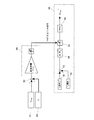
- FIG. 1 shows a control circuit of a DC power assist device according to the present invention, which is applied to control of the power assist device 8 of FIG.
- Reference numeral 9 denotes a setting unit, which is a charge start voltage, a charge target voltage, a charge stop voltage, a non-control voltage range, a discharge stop voltage, a discharge target voltage, and a discharge start depending on the detected value of the DC voltage VDC of the inverter 1 detected. Select and output each set value of voltage. Regarding charge control, discharge control, and non-control, state transition is performed by a comparator in sequence control, and simultaneous control is not performed by interlocking with each other.
- the hatched portions in the setting unit 9 are the charge control holding period and the discharge control holding period, and the charge target value VDCH * and the discharge target value VDCL * are set and output as command values in each period.
- Reference numeral 10 denotes a charge control unit.
- the charge control unit 10 calculates a difference between the set value VDCH * output from the setting unit 9 and the detected value of the DC voltage VDC, and a charge command ichg corresponding to the difference signal.
- the voltage control unit 12 that generates *
- the subtraction unit 13 that calculates the difference between the charge command ichg * and the capacitor current ic of the electric double layer capacitor C detected by the current detection unit Di, the difference calculated by the subtraction unit 13
- the current control unit 14 includes a current control unit 14 that performs current control according to a signal, and a PWM control unit 15 that performs PWM control based on the output of the current control unit 14.
- Reference numeral 20 denotes a discharge controller.
- the discharge controller 20 is a subtractor 21 that calculates the difference between the set value VDCL * output from the setting unit 9 and the detected value of the DC voltage VDC, and corresponds to the calculated difference signal.
- a voltage control unit 22 that generates a discharge command idchg *, and a subtraction that calculates a difference between the discharge command idchg * generated by the voltage control unit 22 and the capacitor current ic of the electric double layer capacitor C detected by the current detection unit Di.
- Unit 23 a current control unit 24 that performs current control according to the difference signal calculated by the subtraction unit 23, and a PWM control unit 25 that executes PWM control based on the output of the current control unit 24.
- Reference numeral 30 denotes a voltage sag high-speed compensator that compensates for an instantaneous voltage drop in the power system.
- the power estimator 31 includes a power estimator 31 and a divider 32 that receive the DC voltage VDC and estimate the power. The division result of the division of the DC voltage VDC is output to the voltage control unit 22.
- the charging control is latched and the charging is stopped. Charge control is executed until the voltage becomes lower than the voltage. The charge control is performed over the charge control holding period, and the DC voltage VDC does not exceed the charge target value VDCH * even when the regenerative load increases by controlling the DC voltage VDC to be the charge target value VDCH *. Be controlled.
- the difference between the set charging target value VDCH * and the detected DC voltage VDC is calculated by the subtractor 11, and the difference signal is input to the voltage controller 12.
- the voltage controller 12 is a controller having a limiter function, and outputs a charge command ichg * corresponding to the difference signal until the limit value is reached.
- the subtractor 13 calculates the difference between the charge command ichg * and the capacitor current ic, inputs the difference signal to the current controller 14, calculates a current control signal for charge control, and outputs it to the PWM controller 15.
- the PWM control unit 15 executes PWM control based on the input signal to generate a signal Gchg *, which becomes a gate signal to the switching element Gc of the chopper unit CH and becomes an on / off signal for charging.
- the discharge control is latched, and the discharge control is performed so that the DC voltage VDC becomes the discharge target value until it becomes equal to or higher than the discharge stop voltage.
- the discharge control is executed by the discharge control unit 20.
- the subtraction unit 21 calculates the difference between the set discharge target value VDCL * and the detected DC voltage VDC, and the difference signal is input to the voltage control unit 22.
- the voltage control unit 22 is a controller having a limiter function, and outputs a discharge command idchg * corresponding to the difference signal until the limit value is reached.
- the subtractor 13 calculates the difference between the discharge command idchg * and the capacitor current ic, inputs the difference signal to the current controller 24, calculates a current control signal for charge control, and outputs it to the PWM controller 25.
- the PWM control unit 25 executes PWM control based on the input signal to generate the signal Gdchg *, becomes a gate signal to the switching element Gd of the chopper unit CH, and controls on / off for discharging until the discharge stop voltage is reached. Is executed.
- the instantaneous voltage drop high-speed compensator 30 is provided to execute the instantaneous voltage drop phenomenon at high speed.
- the instantaneous low-speed compensation unit 30 estimates the power required for the discharge from the discharge energy and outputs a discharge current command. Therefore, the power estimation unit 31 stores the capacitor capacitance CI connected to the DC circuit of the inverter in advance and samples the DC voltage VDC at a time interval of ⁇ t. The following calculation is executed with the sampling value of the DC voltage VDC as the previous value V12 and the current value V22.
- FIG. 2 shows a torque assist control circuit that takes into account the power storage amount.
- the load 6 shown in FIG. 3 is an example in which the speed of the generator M is controlled by the inverter 1 via the motor M, and the generator G is used as mechanical power.
- FIG. 2 is a control circuit for performing torque assist of the mechanical power.
- Reference numeral 81 denotes a discharge threshold value setting unit for setting the terminal voltage discharge threshold value Vedchg * of the electric double layer capacitor C.
- 82 is a terminal voltage detection unit of the electric double layer capacitor C.
- the detection voltage Ve is subtracted from the terminal voltage discharge threshold Vedchg * by a subtraction unit 83, and the difference signal is input to a load compensation gain unit 84 having a limiter function to gain. A compensation signal is obtained.
- These 81-8 4 is provided in the control unit of the DC power assist 8.
- 40 shows a part of an inverter control unit for performing torque assist
- 41 is a q-axis current command setting unit
- 42 is a q-axis current detection unit
- the detected current value is set value Iq *.
- a difference between the two Iqs is calculated by the subtracting unit 43, and a current command for the q-axis corresponding to the difference signal is calculated by the current control unit 44.
- Reference numeral 45 denotes a drive torque limiter unit whose limiter value is varied by a gain compensation signal from the load compensation gain unit 84.
- a PWM control unit 46 generates a PWM signal according to the input signal, and outputs a gate signal of a switching element constituting the inverter.
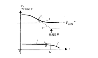
- FIG. 4 shows a state in which torque assist is performed by the control circuit shown in FIG. 2.
- the vertical axis represents the terminal voltage (power storage amount) of the electric double layer capacitor, and the horizontal axis represents time.
- the terminal voltage discharge threshold Vedchg * of the electric double layer capacitor is set to a certain value of the power storage amount.
- Lines a and b are the terminal voltage and torque of the electric double layer capacitor when torque assist control is executed
- lines c and d are the terminal voltage and torque when torque assist control is not performed, and time when torque assist control is not performed.
- the discharge limit is reached at t1.
- the charging and discharging control can be individually set, and the DC voltage can be set according to the equipment.
- the minimum DC voltage required for securing the maximum voltage of the motor or the like is maintained, and the switching loss of the switching elements constituting the inverter and chopper can be reduced.
- unnecessary power assist does not have to be performed, the entire system can be operated efficiently, and the life of the assist device can be extended.
- the control circuit diagram of the direct-current power assist device which shows embodiment of this invention.
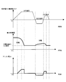
- the torque assist control circuit diagram of the present invention The schematic block diagram of a power converter device. Torque assist state diagram. Control explanatory diagram of load leveling.
Landscapes
- Engineering & Computer Science (AREA)
- Power Engineering (AREA)
- Transportation (AREA)
- Mechanical Engineering (AREA)
- Manufacturing & Machinery (AREA)
- Chemical & Material Sciences (AREA)
- Chemical Kinetics & Catalysis (AREA)
- Electrochemistry (AREA)
- General Chemical & Material Sciences (AREA)
- Inverter Devices (AREA)
- Charge And Discharge Circuits For Batteries Or The Like (AREA)
- Supply And Distribution Of Alternating Current (AREA)
- Secondary Cells (AREA)
- Control Of Electric Motors In General (AREA)
- Dc-Dc Converters (AREA)
Abstract
Description
前記蓄電デバイスに対する充放電制御用の設定部と、この設定部により設定された充電目標値に基づいて充電制御を実行する充電制御部と、設定部により設定された放電目標値に基づいて放電制御を実行する放電制御部と、前記インバータの直流検出電圧に対応した電力を推定し、その推定値を直流検出電圧で除した値を放電制御部に出力する瞬低高速補償部とを備え、
前記設定部は、充電開始電圧、充電停止電圧、無制御電圧範囲、放電停止電圧、及び放電開始電圧の各設定値を有し、且つ各設定値は前記インバータの直流検出電圧の検出値に応じて選択され、充電目標値、放電目標値として充電制御部と放電制御部にそれぞれ出力するよう構成したことを特徴としたものである。
9は設定部で、検出されたインバータ1の直流電圧VDCの検出値に応じて、充電開始電圧、充電目標電圧、充電停止電圧、無制御電圧範囲、放電停止電圧、放電目標電圧、及び放電開始電圧の各設定値を選択し出力する。充電制御、放電制御、無制御については、シーケンス制御にてコンパレータによる状態遷移し、互いにインターロックにて同時制御はしない。設定部9で斜線を付した部分が、充電制御保持期間と放電制御保持期間で、各期間中でそれぞれ充電目標値VDCH*と放電目標値VDCL*とが設定されて指令値として出力される。
、直流電圧VDCを入力して電力を推定する電力推定部31と除算部32を有し、直流電圧から推定された電力推定値と直流電圧VDCとの除算との除算結果は、電圧制御部22に出力される。
負荷6の回生状態がなくなって直流電圧VDCが低下し、充電停止電圧以下になると充電制御は停止される。
まず、設定された放電目標値VDCL*と検出された直流電圧VDCとの差を減算部21で演算し、差信号は電圧制御部22に入力される。電圧制御部22はリミッタ機能を有する制御器で、制限値に達するまでは差信号に応じた放電指令idchg*を出力する。減算部13では放電指令idchg*とキャパシタ電流icとの差を演算し、差信号を電流制御部24に入力して充電制御のための電流制御信号を演算し、PWM制御部25に出力する。PWM制御部25では、入力された信号に基づきPWM制御を実行して信号Gdchg*を生成し、チョッパ部CHのスイッチング素子Gdへのゲート信号となり、放電停止電圧となるまで放電
のためのオンオフ制御が実行される。
ΔW=1/2(CI)(V12-V22)[J]
ΔP=ΔW/Δt[W]
求まった電力の変化分ΔPは、除算部32に入力されて次の演算を実行して放電電流指令idchgi*を求める。
idchgi*=ΔP/VDC
放電電流指令idchgi*は、電圧制御部22、電流制御部24を介してPWM制御部25に入力され、瞬時電圧低下に対応した補償制御が実行される。
なお、直流電圧VDCが充電・放電領域の無制御範囲内にある場合、充電・放電の各ゲート指令を遮断して、例えば商用電力系統のみの運転を継続する。
図3で示す負荷6は、インバータ1によりモータMを介して発電機Mの速度を制御する例で、発電機Gを機械動力としている。図2は、この機械動力のトルクアシストを行うための制御回路である。81は放電閾値設定部で、電気二重層コンデンサCの端子電圧放電閾値Vedchg*が設定される。82は電気二重層コンデンサCの端子電圧検出部で、検出電圧Veは減算部83で端子電圧放電閾値Vedchg*から減算され、その差信号はリミッタ機能を有する負荷補償ゲイン部84に入力されてゲイン補償信号が得られる。これら81~8
4は、直流電力アシスト8の制御部内に設けられる。
また、検出電圧Veが電圧放電閾値Vedchg*に近づくにしたがって次第に駆動トルクリミッタ部45のリミッタを絞ってアシストする量を低減する制御を実行する。
6… 負荷
8… 直流電力アシスト装置
9… 設定部
10… 充電制御部
20… 放電制御部
12、22… 電圧制御部
14、24、44… 電流制御部
15,25、46… PWM制御部
40… インバータ制御部
45… 駆動トルクリミッタ部
84… 負荷補償ゲイン部
Claims (4)
- 交流電力系統に負荷制御用のインバータを接続し、このインバータの直流回路に、チョッパ、蓄電デバイスを有する直流電力アシスト装置を接続して電力アシストを行うものにおいて、
前記蓄電デバイスに対する充放電制御用の設定部と、この設定部により設定された充電目標値に基づいて充電制御を実行する充電制御部と、設定部により設定された放電目標値に基づいて放電制御を実行する放電制御部と、前記インバータの直流検出電圧に対応した電力を推定し、その推定値を直流検出電圧で除した値を放電制御部に出力する瞬低高速補償部とを備え、
前記設定部は、充電開始電圧、充電停止電圧、無制御電圧範囲、放電停止電圧、及び放電開始電圧の各設定値を有し、且つ各設定値は前記インバータの直流検出電圧の検出値に応じて選択され、充電目標値、放電目標値として充電制御部と放電制御部にそれぞれ出力するよう構成したことを特徴とした電力変換装置。 - 前記充電制御部と放電制御部は、充電目標値、放電目標値とインバータの直流検出電圧との偏差信号を各別に入力して充電指令値、放電指令値をそれぞれ演算する電圧制御部と、
各電圧制御部から出力された充電指令値、放電指令値と前記蓄電デバイスの検出電流との偏差を各別に入力して電流演算する電流制御部と、各電流制御部からの充電指令値、放電指令値をそれぞれ各別に入力し、前記チョッパの充電用スイッチング素子と放電用スイッチング素子のゲート信号を各別に生成するPWM制御部とを備えたことを特徴とした請求項1記載の電力変換装置。 - 瞬低高速補償部は、前記インバータのチュク流回路に設置されるコンデンサの容量と、入力される直流検出電圧のサンプリング値によって放電エネルギーの変化分から電力の変化分を算出し、算出された電力の変化分を直流検出電圧で除すことで放電電流指令を生成することを特徴とした請求項1又は2記載の電力変換装置。
- 前記蓄電デバイスの設定された端子電圧放電閾値と、検出された蓄電デバイスの端子電圧との偏差信号に応じたゲイン補償信号を演算する負荷補償ゲイン部を設けると共に、前記インバータの制御部が有する電流制御部の出力側に駆動トルクリミッタ部を設け、この駆動トルクリミッタ部のリミッタ値を前記負荷補償ゲイン部が出力するゲイン補償信号で可変するよう構成したことを特徴とした請求項1乃至3記載の何れかである電力変換装置。
Priority Applications (3)
| Application Number | Priority Date | Filing Date | Title |
|---|---|---|---|
| CN2009801099134A CN101978570B (zh) | 2008-03-21 | 2009-03-19 | 电力变换装置 |
| GB1017826.7A GB2471430B (en) | 2008-03-21 | 2009-03-19 | Power conversion device |
| US12/933,206 US8482245B2 (en) | 2008-03-21 | 2009-03-19 | Power conversion device |
Applications Claiming Priority (2)
| Application Number | Priority Date | Filing Date | Title |
|---|---|---|---|
| JP2008072825A JP5358990B2 (ja) | 2008-03-21 | 2008-03-21 | 電力変換装置 |
| JP2008-072825 | 2008-03-21 |
Publications (1)
| Publication Number | Publication Date |
|---|---|
| WO2009116641A1 true WO2009116641A1 (ja) | 2009-09-24 |
Family
ID=41091039
Family Applications (1)
| Application Number | Title | Priority Date | Filing Date |
|---|---|---|---|
| PCT/JP2009/055491 Ceased WO2009116641A1 (ja) | 2008-03-21 | 2009-03-19 | 電力変換装置 |
Country Status (5)
| Country | Link |
|---|---|
| US (1) | US8482245B2 (ja) |
| JP (1) | JP5358990B2 (ja) |
| CN (1) | CN101978570B (ja) |
| GB (1) | GB2471430B (ja) |
| WO (1) | WO2009116641A1 (ja) |
Cited By (1)
| Publication number | Priority date | Publication date | Assignee | Title |
|---|---|---|---|---|
| CN102918411A (zh) * | 2010-06-07 | 2013-02-06 | 三菱电机株式会社 | 充电状态推定装置 |
Families Citing this family (12)
| Publication number | Priority date | Publication date | Assignee | Title |
|---|---|---|---|---|
| CN103026606B (zh) * | 2010-07-28 | 2015-08-05 | 三菱电机株式会社 | 斩波器装置 |
| JP5673267B2 (ja) * | 2011-03-22 | 2015-02-18 | 株式会社明電舎 | 電力用チョッパの制御装置 |
| DE102011086829A1 (de) * | 2011-11-22 | 2013-05-23 | Continental Automotive Gmbh | Bordnetz und Verfahren zum Betreiben eines Bordnetzes |
| KR101224570B1 (ko) * | 2011-12-12 | 2013-01-21 | 주식회사 우진산전 | 철도차량의 에너지 저장 시스템 기반 자동 튜닝 방법 |
| KR101191244B1 (ko) * | 2012-01-05 | 2012-10-18 | 주식회사 우진산전 | 양방향 디씨-디씨 컨버터를 이용한 도시철도의 에너지 저장장치 |
| JP2013192413A (ja) | 2012-03-15 | 2013-09-26 | Omron Corp | 蓄電デバイス制御方法、蓄電デバイス制御装置、蓄電デバイス制御システム |
| JP2014176226A (ja) * | 2013-03-11 | 2014-09-22 | Sumitomo Electric Ind Ltd | Dc/dc変換装置及び分散電源システム |
| JP6357343B2 (ja) * | 2014-04-25 | 2018-07-11 | 株式会社日立製作所 | 電力貯蔵装置 |
| JP6420684B2 (ja) * | 2015-02-17 | 2018-11-07 | 株式会社日立製作所 | 電力貯蔵装置 |
| JP6711466B2 (ja) * | 2017-09-15 | 2020-06-17 | 株式会社村田製作所 | 蓄電装置用昇降圧装置及び蓄電装置 |
| EP3503382B1 (en) * | 2017-12-21 | 2020-12-02 | Valeo Siemens eAutomotive Germany GmbH | Method and apparatus for determining a measuring offset of a rotor position sensor |
| EP3883115A4 (en) * | 2018-11-14 | 2022-06-22 | Toshiba Mitsubishi-Electric Industrial Systems Corporation | CURRENT TRANSFORMING DEVICE |
Citations (3)
| Publication number | Priority date | Publication date | Assignee | Title |
|---|---|---|---|---|
| JP2002325465A (ja) * | 2001-04-26 | 2002-11-08 | Hitachi Ltd | 交流電源装置 |
| JP2003052134A (ja) * | 2001-08-07 | 2003-02-21 | Mitsubishi Electric Corp | 無停電電源装置の制御方法およびこの方法を用いた無停電電源装置 |
| JP2003111493A (ja) * | 2001-09-26 | 2003-04-11 | Mitsubishi Electric Corp | 電動機駆動システム |
Family Cites Families (6)
| Publication number | Priority date | Publication date | Assignee | Title |
|---|---|---|---|---|
| JP2002369407A (ja) * | 2001-06-06 | 2002-12-20 | Hitachi Ltd | ピークカット機能付きバックアップ電源 |
| KR100639447B1 (ko) * | 2003-04-14 | 2006-10-26 | 마츠시타 덴끼 산교 가부시키가이샤 | 모터 구동 장치, 압축기, 공기 조화기, 냉장고, 전기 세탁기, 송풍기, 전기 청소기, 전기 건조기 및 열 펌프 급탕기 |
| JP4347277B2 (ja) | 2005-08-24 | 2009-10-21 | 三菱電機株式会社 | 電力バッファ装置システム |
| JP4067554B2 (ja) * | 2006-01-31 | 2008-03-26 | 株式会社パワーシステム | 蓄電装置 |
| JP4743082B2 (ja) * | 2006-11-01 | 2011-08-10 | トヨタ自動車株式会社 | 電源システムおよびそれを備えた車両 |
| US7615887B2 (en) * | 2007-03-09 | 2009-11-10 | Gm Global Technology Operations, Inc. | Method and system for operating a power converter |
-
2008
- 2008-03-21 JP JP2008072825A patent/JP5358990B2/ja not_active Expired - Fee Related
-
2009
- 2009-03-19 GB GB1017826.7A patent/GB2471430B/en not_active Expired - Fee Related
- 2009-03-19 US US12/933,206 patent/US8482245B2/en not_active Expired - Fee Related
- 2009-03-19 WO PCT/JP2009/055491 patent/WO2009116641A1/ja not_active Ceased
- 2009-03-19 CN CN2009801099134A patent/CN101978570B/zh not_active Expired - Fee Related
Patent Citations (3)
| Publication number | Priority date | Publication date | Assignee | Title |
|---|---|---|---|---|
| JP2002325465A (ja) * | 2001-04-26 | 2002-11-08 | Hitachi Ltd | 交流電源装置 |
| JP2003052134A (ja) * | 2001-08-07 | 2003-02-21 | Mitsubishi Electric Corp | 無停電電源装置の制御方法およびこの方法を用いた無停電電源装置 |
| JP2003111493A (ja) * | 2001-09-26 | 2003-04-11 | Mitsubishi Electric Corp | 電動機駆動システム |
Cited By (2)
| Publication number | Priority date | Publication date | Assignee | Title |
|---|---|---|---|---|
| CN102918411A (zh) * | 2010-06-07 | 2013-02-06 | 三菱电机株式会社 | 充电状态推定装置 |
| CN102918411B (zh) * | 2010-06-07 | 2015-02-25 | 三菱电机株式会社 | 充电状态推定装置 |
Also Published As
| Publication number | Publication date |
|---|---|
| GB2471430A (en) | 2010-12-29 |
| CN101978570B (zh) | 2013-05-15 |
| JP2009232526A (ja) | 2009-10-08 |
| GB2471430B (en) | 2012-09-26 |
| JP5358990B2 (ja) | 2013-12-04 |
| US20110001464A1 (en) | 2011-01-06 |
| CN101978570A (zh) | 2011-02-16 |
| US8482245B2 (en) | 2013-07-09 |
| GB201017826D0 (en) | 2010-12-01 |
Similar Documents
| Publication | Publication Date | Title |
|---|---|---|
| JP5358990B2 (ja) | 電力変換装置 | |
| JP4428049B2 (ja) | エレベータにおけるインバータ用直流電源のバックアップ方法とその装置 | |
| JP4536128B2 (ja) | Dc/dcコンバータ装置及びこのdc/dcコンバータ装置が搭載された燃料電池車両、並びにdc/dcコンバータの制御方法 | |
| KR101420987B1 (ko) | 교류 모터 구동 장치 | |
| JP5381026B2 (ja) | 複合電源装置の制御回路 | |
| JP5094831B2 (ja) | エレベーターシステム | |
| US9893617B2 (en) | Electric power conversion system | |
| JP6496496B2 (ja) | 電力貯蔵システムおよびその制御方法 | |
| WO2015194013A1 (ja) | 交流モータ駆動システム | |
| US9543882B2 (en) | AC motor drive system | |
| JPWO2014136142A1 (ja) | 交流モータ駆動システム | |
| JP2018075958A5 (ja) | ||
| JP5123673B2 (ja) | 電力変換装置 | |
| JP5245498B2 (ja) | 電力アシスト装置 | |
| JP4805302B2 (ja) | Dc/dcコンバータ装置の動作制御方法 | |
| US20120109549A1 (en) | Electrical power control device and electrical power calculation method in electrical power control device | |
| JP4192609B2 (ja) | 直流電力変換システム | |
| JP5673267B2 (ja) | 電力用チョッパの制御装置 | |
| JP6296878B2 (ja) | 系統連系インバータおよび発電電力推定方法 | |
| KR101509818B1 (ko) | 양방향 컨버터의 제어기 및 그의 구동 방법 | |
| JP7451944B2 (ja) | 電気自動車 | |
| JP5262727B2 (ja) | 直流電源の制御方法および前記直流電源の制御方法を用いた移動車両 | |
| JP6357343B2 (ja) | 電力貯蔵装置 | |
| JP2004336888A (ja) | 電力補償装置及び方法 | |
| JP2011210665A (ja) | バッテリシミュレータおよびその制御方法 |
Legal Events
| Date | Code | Title | Description |
|---|---|---|---|
| WWE | Wipo information: entry into national phase |
Ref document number: 200980109913.4 Country of ref document: CN |
|
| 121 | Ep: the epo has been informed by wipo that ep was designated in this application |
Ref document number: 09722943 Country of ref document: EP Kind code of ref document: A1 |
|
| WWE | Wipo information: entry into national phase |
Ref document number: 12933206 Country of ref document: US |
|
| NENP | Non-entry into the national phase |
Ref country code: DE |
|
| ENP | Entry into the national phase |
Ref document number: 1017826 Country of ref document: GB Kind code of ref document: A Free format text: PCT FILING DATE = 20090319 |
|
| WWE | Wipo information: entry into national phase |
Ref document number: 1017826.7 Country of ref document: GB |
|
| 122 | Ep: pct application non-entry in european phase |
Ref document number: 09722943 Country of ref document: EP Kind code of ref document: A1 |