WO2009116303A1 - Method for judging combustion state of internal combustion - Google Patents
Method for judging combustion state of internal combustion Download PDFInfo
- Publication number
- WO2009116303A1 WO2009116303A1 PCT/JP2009/050015 JP2009050015W WO2009116303A1 WO 2009116303 A1 WO2009116303 A1 WO 2009116303A1 JP 2009050015 W JP2009050015 W JP 2009050015W WO 2009116303 A1 WO2009116303 A1 WO 2009116303A1
- Authority
- WO
- WIPO (PCT)
- Prior art keywords
- current
- resonance
- detected
- combustion
- combustion state
- Prior art date
Links
Images


Classifications
-
- F—MECHANICAL ENGINEERING; LIGHTING; HEATING; WEAPONS; BLASTING
- F02—COMBUSTION ENGINES; HOT-GAS OR COMBUSTION-PRODUCT ENGINE PLANTS
- F02P—IGNITION, OTHER THAN COMPRESSION IGNITION, FOR INTERNAL-COMBUSTION ENGINES; TESTING OF IGNITION TIMING IN COMPRESSION-IGNITION ENGINES
- F02P17/00—Testing of ignition installations, e.g. in combination with adjusting; Testing of ignition timing in compression-ignition engines
- F02P17/12—Testing characteristics of the spark, ignition voltage or current
-
- F—MECHANICAL ENGINEERING; LIGHTING; HEATING; WEAPONS; BLASTING
- F02—COMBUSTION ENGINES; HOT-GAS OR COMBUSTION-PRODUCT ENGINE PLANTS
- F02D—CONTROLLING COMBUSTION ENGINES
- F02D35/00—Controlling engines, dependent on conditions exterior or interior to engines, not otherwise provided for
- F02D35/02—Controlling engines, dependent on conditions exterior or interior to engines, not otherwise provided for on interior conditions
- F02D35/021—Controlling engines, dependent on conditions exterior or interior to engines, not otherwise provided for on interior conditions using an ionic current sensor
-
- G—PHYSICS
- G01—MEASURING; TESTING
- G01M—TESTING STATIC OR DYNAMIC BALANCE OF MACHINES OR STRUCTURES; TESTING OF STRUCTURES OR APPARATUS, NOT OTHERWISE PROVIDED FOR
- G01M15/00—Testing of engines
- G01M15/04—Testing internal-combustion engines
- G01M15/11—Testing internal-combustion engines by detecting misfire
-
- F—MECHANICAL ENGINEERING; LIGHTING; HEATING; WEAPONS; BLASTING
- F02—COMBUSTION ENGINES; HOT-GAS OR COMBUSTION-PRODUCT ENGINE PLANTS
- F02D—CONTROLLING COMBUSTION ENGINES
- F02D2200/00—Input parameters for engine control
- F02D2200/02—Input parameters for engine control the parameters being related to the engine
- F02D2200/10—Parameters related to the engine output, e.g. engine torque or engine speed
- F02D2200/1015—Engines misfires
Definitions
- the present invention relates to a combustion state determination method for an internal combustion engine using an electric current generated at the end of discharge of the spark plug in an internal combustion engine having an ion current detection circuit connected to the spark plug.
- an ionic current is generated for each ignition in a combustion chamber of an internal combustion engine, the generated ionic current is detected, and a combustion state is often determined based on the waveform of the ionic current.
- an ionic current detected in a discharge time zone from when a signal is issued to discharge from the spark plug until the discharge is terminated includes an ignition coil at the end of the spark plug discharge.
- the timing of starting the detection of the ion current is experimentally determined at a time point when it can be determined that the current derived from the LC resonance is sufficiently attenuated during combustion, and is set at this time point.
- a phenomenon called noise dripping occurs in which the current gradually occurs in the ion current detection circuit due to the discharge of the charge remaining on the electrode of the spark plug, as shown in FIG.
- the current may be detected after the start of detection of the ion current.
- the combustion state is determined based on the ion current detected during the period after the time when it can be determined that the current derived from the LC resonance is sufficiently attenuated during combustion, in FIG.
- the present invention is configured to solve such problems.
- a combustion state determination method for an internal combustion engine is a combustion state determination method for an internal combustion engine in which an ion current detection circuit is connected to the ignition plug, and the ignition coil secondary side and the ignition plug are The current generated on the secondary side of the ignition coil due to the LC resonance between and is detected, and the combustion state is determined based on the waveform shape derived from the LC resonance of the detected current.
- the waveform of the current derived from the LC resonance at the time of misfiring has a longer duration, such as the shape of the detected current waveform is different from that at the time of combustion. Since misfire determination is performed based on the shape of the above, it is possible to prevent the occurrence of a malfunction that is erroneously determined that no misfire has occurred due to noise or corona noise. Also, since the current immediately after the end of the discharge is detected, the ion current can be detected even when the combustion ends early, so that if the combustion is fast, it is erroneously determined that a misfire has occurred even though normal combustion has been performed. It is also possible to prevent the occurrence of malfunctions.
- the “LC resonance between the secondary side of the ignition coil and the ignition plug” is a concept including LC resonance between the secondary side of the ignition coil and the capacitor of the ion current detection circuit connected to the ignition plug.
- One aspect in which the occurrence of the malfunction can be particularly effectively prevented is that a misfire is determined when the duration of the waveform derived from the LC resonance of the detected current exceeds a predetermined value. . This is because the duration of the current is long in the misfire state as described above.
- the duration of the waveform derived from the LC resonance As a preferred method for measuring the length of the waveform derived from the LC resonance, the length of the period from the fall of the first detected signal current to the last fall of the detected signal current is measured. To do.
- Another aspect in which the occurrence of the malfunction can be particularly effectively prevented is that the engine is determined to be in a misfire state when the integrated value of the detected current is below a predetermined value.
- the ion current detection circuit when used, the ion current is superimposed on the current derived from the LC resonance in the combustion state, whereas the ion current is superimposed on the current derived from the LC resonance in the misfire state. This is because the intensity of the detected current is weakened.
- the ion current detection circuit when using the ion current detection circuit, the current detected by superimposing the ion current on the current derived from the LC resonance in the combustion state changes gently, and the frequency of the waveform becomes low, In addition, while a plurality of frequency components are included, in the misfire state, the ion current is not superimposed on the current derived from the LC resonance, and the frequency components of the detected current are substantially within a predetermined range, and the ion current It is because it vibrates at a higher frequency compared with the case where is superimposed. *
- Another example of an aspect that can effectively prevent the occurrence of the above-described problem includes a case in which a misfire state is determined when the detected current peak value is attenuated.
- the LC resonance current is mainly detected, and this LC resonance current is often attenuated while oscillating at a predetermined period.
- the LC resonance current is superimposed on the ion current Iion. This is because the peak value of the detected current is often larger than the initial peak value of the LC resonance current.
- the waveform of the current derived from the LC resonance at the time of misfiring has a longer duration, such as the shape of the detected current waveform being different from that at the time of combustion.
- misfire determination is performed based on the shape of this waveform, it is possible to prevent the occurrence of a malfunction that is erroneously determined that misfire has not occurred at the time of misfire due to prolonged current derived from LC resonance or corona noise.
- the ion current can be detected even when the combustion ends early, so that if the combustion is fast, it is erroneously determined that a misfire has occurred even though normal combustion has been performed. It is also possible to prevent the occurrence of malfunctions.
- FIG. 1 is a schematic diagram showing an ignition circuit and an ion current detection circuit according to an embodiment of the present invention.
- the flowchart which shows the flow of control in the combustion time measurement program which concerns on the embodiment. Action
- the flowchart which shows the flow of control in the combustion time measurement program which concerns on the other embodiment of this invention.
- An engine 100 which is an internal combustion engine schematically shown in FIG. 1, is a four-cylinder engine for an automobile.
- a throttle valve 2 that opens and closes in response to an accelerator pedal (not shown) is disposed in an intake system 1 thereof. Is provided with a surge tank 3.
- a fuel injection valve 5 is further provided in the vicinity of one end of the intake manifold 4 of the intake system 1 communicating with the surge tank 3 and communicating with the cylinder 10 via the intake valve 10a.
- the electronic control unit 6 controls each cylinder to inject independently.
- an O 2 sensor 21 that is an air-fuel ratio sensor for measuring the oxygen concentration in the exhaust gas is provided upstream of the three-way catalyst 22 disposed in a pipeline leading to a muffler (not shown). Is attached in position.
- the O 2 sensor 21 has substantially the same configuration as that known as a normal O 2 sensor. That is, a voltage is generated by the difference in oxygen concentration between the atmosphere side electrode and the exhaust side electrode, and it can be determined based on this voltage whether the air-fuel ratio is richer or leaner than the stoichiometric air-fuel ratio.
- the electronic control device 6 is mainly composed of a microcomputer system including a central processing unit 7, a storage device 8, an input interface 9, and an output interface 11.
- the input interface 9 includes: Intake pressure signal a from the intake pressure sensor 13 for detecting the pressure in the surge tank 3, a rotation speed signal b from the rotation speed sensor 14 for detecting the engine speed NE, and a vehicle speed sensor for detecting the vehicle speed 15, a vehicle speed signal c from the idle switch 16, an LL signal d from the idle switch 16 for detecting the open / close state of the throttle valve 2, a water temperature signal e from the water temperature sensor 17 for detecting the cooling water temperature of the engine, the O 2 sensor described above.
- a current signal h from 21 is input.
- the output interface 11 outputs a fuel injection signal f to the fuel injection valve 5 and an ignition pulse g to the spark plug 18.
- An ion current measuring circuit 25 is connected to the spark plug 18 in order to detect the ion current Iion.
- the spark plug 18 is connected to an ignition circuit 24 including at least an ignition coil 24 a and a switching transistor 24 b, and thus the ion current detection circuit 25 is also connected to the ignition circuit 24.
- the ion current detection circuit 25 has Zener diodes 25a and 25b connected in series in opposite directions, and is connected in parallel to one Zener diode 25a, and counter electromotive force generated in the ignition coil 24a.
- a capacitor 25d that generates a detection voltage and an amplifier 25c that amplifies and outputs the ion current Iion.
- the ion current Iion is output from the amplifier 25c of the ion current detection circuit 25 to the comparator 26 which is a waveform shaping circuit.
- the comparator 26 shapes and outputs an ion current Iion, which is an analog signal generated by applying a voltage, into a square wave (pulse) shape. Specifically, as shown in FIG. 2, the comparator 26 compares a predetermined current value Iref having a strength corresponding to a preset threshold value of the ion current Iion with the ion current Iion, and compares the ion current Iion.
- the output terminal of the comparator 26 is connected to the central processing unit 7 through the input interface 9.
- the electronic control device 6 uses the intake pressure signal a output from the intake pressure sensor 13 and the rotation speed signal b output from the rotation speed sensor 14 as main information, and various correction coefficients determined according to the engine situation.
- the fuel injection valve opening time that is, the injector final energization time T is determined by correcting the basic injection time, and the fuel injection valve 5 is controlled by the determined energization time, and fuel corresponding to the engine load is supplied to the fuel injection valve 5.
- the program for injecting into the intake system 1 is built in.
- the electronic control device 6 generates the secondary side of the ignition coil 24a due to LC resonance between the ignition coil 24a and the capacitor 25d of the ion current detection circuit 25 at the end of the discharge of the ignition plug 18.
- a combustion state determination program for detecting an ion current Iion including a current to be detected (hereinafter referred to as an LC resonance current) and determining a combustion state based on the waveform shape of the detected current is further incorporated. More specifically, the combustion state determination program is configured such that a predetermined measurement end point T3 is measured from a measurement start point T2 after a predetermined time required to sufficiently attenuate noise generated at the end of ignition from the falling time T1 of the ignition signal.
- the signal current Iout falls and rises sequentially, and the waveform duration derived from the LC resonance of the detected current, that is, the first detected signal current Iout falls from the last.
- Is measured as the duration of the waveform derived from the LC resonance current (hereinafter referred to as LC resonance current duration spksted), and the duration spksted is greater than or equal to a predetermined value Ts. If there is, it is determined that there is a misfire condition.
- the length of the period from the time T1 to the measurement start point T2 that is, the length of the predetermined period necessary for sufficiently reducing the noise generated at the end of ignition, is set to a predetermined value obtained experimentally in advance. ing.
- the length of the period from the measurement start point T2 to the measurement end point T3, that is, the length of the discharge time zone is calculated from the measurement start point.
- the current derived from the LC resonance is It is experimentally determined as the length of the period until it can be determined that it is sufficiently attenuated.
- FIGS. 4 to 7 which show changes over time in the ion current Iion, the signal current Iout, and the ignition signal with respect to a common time axis
- a bias voltage is applied to the spark plug 18 and an LC resonance current is generated after the end of discharge, and an ion current Iion is generated in the combustion chamber 30 during combustion.
- the magnitude i of the LC resonance current is expressed by the following equation.
- C is the capacity of the capacitor 25d
- L is the inductance on the secondary side of the ignition coil 24a
- V is the blow-off voltage of the capacitor 25d at the end of discharge
- R is the combustion of the air-fuel mixture between both electrodes of the spark plug 18 This is a resistance component that accompanies the generation of ions.
- 4 shows a case where only an LC resonance current is generated during combustion
- FIG. 5 shows a case where a dripping noise occurs after discharge in addition to the LC resonance current
- FIG. 7 shows an addition to the LC resonance current. The case where spike noise occurs is shown respectively.
- the LC resonance current is quickly attenuated because the resistance component R is present between both electrodes of the spark plug 18 during combustion, that is, the duration is shortened. Since the resistance component R is not present, the deceleration is delayed, that is, the duration of the LC resonance current is increased.
- FIG. 3 is a flowchart.
- step S1 the LC resonance current duration spksted is measured. Then, the process proceeds to step S2. Specifically, the period from the first detected signal current Iout to the last detected signal current Iout is measured.
- step S2 it is determined whether or not the LC resonance current duration spksted exceeds a predetermined value Ts. If the LC resonance current duration spksted exceeds the predetermined value Ts, the process proceeds to step S3. Otherwise, the process proceeds to step S4.
- step S3 it is determined that the engine 100 is in a misfire state, and this combustion state determination program is terminated.
- step S4 it is determined that the engine 100 is in a combustion state, and this combustion state determination program is terminated.
- the LC resonance current duration spksted is shorter than the LC resonance current duration spksted in the misfire state as shown in FIGS. It is determined that the LC resonance current duration spksted does not exceed the predetermined value Ts. That is, the processes of steps S 1 ⁇ S 2 ⁇ S 4 are sequentially performed, and it is determined that engine 100 is in the combustion state.
- the misfire state the LC resonance current duration spksted is long, and it is determined in step S2 that the LC resonance current duration spksted exceeds the predetermined value Ts. That is, the processes of steps S1 ⁇ S2 ⁇ S3 are sequentially performed, and it is determined that engine 100 is in a misfire state.
- the duration of the LC resonance current spksted is increased during a misfire, and the engine 100 misfires when the duration spksted exceeds a predetermined value Ts. It determines with it being in a state, and when that is not right, it determines with the engine 100 being a combustion state. Since this determination is performed irrespective of the ion current after the measurement end point T3 used for determination of the combustion state using the conventional ion current, in the case where a noise droop as shown in FIG. Even if a corona noise as shown in FIG. 7 occurs in a misfire state, it can be determined that the misfire state is correct.
- the detection of the ion current Iion is started from the measurement start time after the time required for the LC resonance current to sufficiently attenuate during combustion from the end of the conventional ignition, that is, the measurement end point T3 in the present embodiment. It is possible to prevent the occurrence of a malfunction, that is, a malfunction that is misjudged as not misfiring at the time of misfire due to the occurrence of a malfunction, that is, noise droop or corona noise. Also, since the ion current Iion is detected until the time required for the LC resonance current to sufficiently attenuate at the time of combustion after the end of the discharge, the ion current Iion associated with the combustion can be detected even when the combustion ends early. It is also possible to prevent the occurrence of a malfunction that is erroneously determined to be a misfire state even though normal combustion is performed when combustion is fast.
- the time from the first detection of the fall of the signal current Iout, that is, the rise of the ion current Iion, to the last detection of the fall of the signal current Iout, that is, the rise of the ion current Iion is LC resonance.
- the current duration is measured as spksted, and the engine combustion state is determined using this duration spksted, but is measured after the trailing edge of the signal current Iout, that is, the leading edge of the ion current Iion is detected.
- the time until the end point T3 is measured as the time spksted2 after the end of the resonance detection from the end of the LC resonance current detection to the measurement end point T3, and if the time after the end of the resonance detection spksted2 is equal to or greater than a predetermined value, You may employ
- the combustion state is determined when the ratio Rs is equal to or greater than a predetermined value.
- the combustion state may be determined using any two of the LC resonance current duration spksted, the resonance detection end time spksted2, and the ratio Rs.
- the starting point of the measurement of the duration may be the measurement start point T2 instead of the time when the falling edge of the ion current Iion is first detected.
- the ion current Iion when the ion current Iion is not detected, it is better to determine that the state is misfire. This is because at the time of misfire, the discharge period, that is, the time from the end of ignition to the generation of the LC resonance current is long, and the LC resonance current may be generated after the measurement end point T3.
- a mode in which a misfire state is determined when the frequency of the detected current is equal to or higher than a predetermined value is also conceivable.
- the number of times that the signal current Iout falls, that is, the number of times that the ion current Iion exceeds a predetermined threshold value Iref is measured, and the ion current Iion is predetermined.
- the following process may be performed as a combustion state determination program instead of the processes in steps S1 to S4 in the above-described embodiment.
- An outline procedure of this process will be described with reference to FIG. 8 which is a flowchart.
- step S11 the number of times C the signal current Iout falls is measured. That is, the number of times that the ion current Iion exceeds a predetermined threshold value Iref, that is, the number of interruptions is measured. Then, the process proceeds to step S12.
- step S12 it is determined whether or not the number C of times the signal current Iout has fallen exceeds a predetermined value CC. If the number C of times the signal current Iout has fallen exceeds the predetermined value CC, the process proceeds to step S13. Otherwise, the process proceeds to step S14.
- step S13 it is determined that the engine 100 is in a misfire state, and this combustion state determination program is terminated.
- step S14 it is determined that the engine 100 is in a combustion state, and this combustion state determination program is terminated.
- the LC resonance current is mainly detected, the LC resonance current vibrates at a substantially constant frequency, and the detected ion current Iion falls below a predetermined threshold value Iref between peaks.
- the ion current Iion again exceeds the predetermined threshold value Iref when approaching 0 and approaching the next peak, the frequency of the signal current Iout falling and rising with the peak of the ion current Iion increases.
- this LC resonance current is superimposed on the ionic current accompanying combustion during combustion, the rising of the signal current Iout is not observed until the measurement end point T3 after the start of combustion, so the number of interruptions is small compared to the misfire state.
- the misfire condition can be accurately detected. Also, instead of measuring the number of interruptions, when the frequency component is extracted by Fourier transforming the waveform of the ion current Iion, and the ratio of the extracted frequency component that is greater than or equal to a predetermined threshold is greater than or equal to a predetermined allowable value An aspect in which the engine 100 is determined to be in a misfire state is also conceivable.
- a mode in which the misfire state is determined when the frequency components of the detected current are almost all within the predetermined range that is, when the time interval between the peaks of the detected ion current Iion is substantially constant, is also conceivable.
- a mode in which a misfire state is determined when the ratio of the frequency components of the detected current within a predetermined range exceeds a predetermined threshold LL can be considered.
- the following process may be performed as a combustion state determination program instead of the processes in steps S1 to S4 in the above-described embodiment.
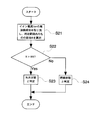
- An outline procedure of this process will be described with reference to FIG. 9 which is a flowchart.
- step S21 the frequency component of the detected ion current Iion is taken out, and the ratio R of those within a predetermined range is calculated.
- the extraction of the frequency component is performed by, for example, Fourier transforming the waveform of the ion current Iion to extract the frequency component. Then, the process proceeds to step S22.
- step S22 it is determined whether or not the ratio R of the extracted frequency components within the predetermined range exceeds a predetermined value RR.
- the process proceeds to step S23. Otherwise, the process proceeds to step S24.
- step S23 it is determined that the engine 100 is in a misfire state, and this combustion state determination program is terminated.
- step S24 it is determined that the engine 100 is in a combustion state, and this combustion state determination program is terminated.
- the misfire state is assumed when the ratio of the frequency component within the predetermined range is equal to or greater than the predetermined threshold LL.
- the predetermined range of the frequency is experimentally obtained in advance as an average LC resonance current frequency in a misfire state.
- the frequency components of the detected current are substantially all within the predetermined range. You may employ
- the LC resonance current is mainly detected at the time of misfire, and this LC resonance current is often attenuated while oscillating at a predetermined period. This is because the peak value of the detected current is often larger than the initial peak value of the LC resonance current.
- the time derivative of the ion current Iion may be detected, and it may be determined that the vehicle is misfiring when the peak value of the time derivative is equal to or greater than a predetermined value.
- the LC resonance current is mainly detected in the misfire state, and this LC resonance current vibrates at a high frequency, whereas in the combustion state, the LC resonance current and the ionic current are detected to be superposed, and the change with time is comparatively gentle. Because.
- the mode which determines with a misfire state can be considered when the integral value IIion of the ion current Iion is less than the predetermined value TI.
- the following process may be performed as a combustion state determination program instead of the processes in steps S1 to S4 in the above-described embodiment.
- An outline procedure of this processing will be described with reference to FIG. 10 which is a flowchart.
- the ion current Iion at each time is measured in an analog manner, and a waveform is obtained by storing the measured ion current Iion in association with the time, and the integration of the ion current Iion is based on this waveform.
- the value IIion is calculated.
- step S31 an integral value IIion of the ion current Iion from the fall of the ignition signal to the end of the discharge time zone is calculated. Then, the process proceeds to step S32.
- step S32 it is determined whether or not the integral value IIion of the ion current Iion exceeds a predetermined value TI. If the integral value IIion exceeds the predetermined value TI, the process proceeds to step S33. Otherwise, the process proceeds to step S34.
- step S33 it is determined that the engine 100 is in a combustion state, and this combustion state determination program is terminated.
- step S34 it is determined that the engine 100 is in a misfire state, and this combustion state determination program is terminated.
- the LC resonance current is mainly detected, and the detected current vibrates at a predetermined cycle.
- the peak intensity after the second time is the peak of the first time. Does not exceed strength. Accordingly, the integral value IIion of the ion current Iion increases in the combustion state and decreases in the event of a misfire.
- the problem that occurs in the mode in which the ion current Iion is detected from the measurement start point after the lapse of time necessary for the LC resonance current to sufficiently attenuate at the time of combustion from the end of the conventional ignition that is, no noise It is possible to prevent the occurrence of a malfunction that is erroneously determined that the misfire has not occurred due to the occurrence of a corona noise or the like. Also, since the ion current Iion is detected until the time required for the LC resonance current to sufficiently attenuate at the time of combustion after the end of the discharge, the ion current Iion associated with the combustion can be detected even when the combustion ends early. It is also possible to prevent the occurrence of a malfunction that is erroneously determined to be a misfire state even though normal combustion is performed when combustion is fast.
- the ion current can be detected even when the combustion ends early, so that if the combustion is fast, it is erroneously determined that a misfire has occurred even though normal combustion has been performed. It is also possible to prevent the occurrence of malfunctions.
Abstract
In a combustion state judgment method, current is detected that, when the discharge of a spark plug is completed, is induced on the secondary side of an ignition coil as a result of the LC resonance between the secondary side of the ignition coil and the spark plug. A combustion state is then judged based on the waveform shape of the detected current, which is originated from the LC resonance.
Description
本発明は、点火プラグにイオン電流検出回路を接続した内燃機関において、点火プラグの放電終了時に発生する電流を利用した内燃機関の燃焼状態判定方法に関する。
The present invention relates to a combustion state determination method for an internal combustion engine using an electric current generated at the end of discharge of the spark plug in an internal combustion engine having an ion current detection circuit connected to the spark plug.
従来、内燃機関の燃焼室内に、点火ごとにイオン電流を発生させ、発生させたイオン電流を検出し、このイオン電流の波形に基づいて燃焼状態を判断することが多く行われてきている。このような燃焼状態の判断において、従来は、点火プラグから放電を行うべく信号を発した後放電が終了するまでの放電時間帯に検出されるイオン電流には、点火プラグの放電終了時に点火コイルの二次側とイオン電流検出回路の電源コンデンサとの間のLC共振に由来して前記二次コイルに発生する電流が重なるので、このLC共振に由来する電流が十分減衰するのを待ってイオン電流の検出を開始する態様が広く採用されている(例えば、特許文献1を参照)。
特開平7-286552号公報
2. Description of the Related Art Conventionally, an ionic current is generated for each ignition in a combustion chamber of an internal combustion engine, the generated ionic current is detected, and a combustion state is often determined based on the waveform of the ionic current. In the determination of such a combustion state, conventionally, an ionic current detected in a discharge time zone from when a signal is issued to discharge from the spark plug until the discharge is terminated includes an ignition coil at the end of the spark plug discharge. Since the current generated in the secondary coil overlaps due to the LC resonance between the secondary side of the ion current detection circuit and the power supply capacitor of the ion current detection circuit, the ion generated after the current resulting from the LC resonance is sufficiently attenuated A mode in which detection of current is started is widely adopted (see, for example, Patent Document 1).
JP-A-7-286552
ところで、イオン電流の検出を開始するタイミングは、燃焼時に前記LC共振に由来する電流が十分減衰すると判定できる時点を実験的に決定し、この時点に設定している。しかし、失火時において、点火プラグの電極に残留した電荷の放電に起因して電流が徐々にイオン電流検出回路に発生するノイズだれと呼ばれる現象が起こることがあり、図6に示すように、この電流がイオン電流の検出開始以後に検出されることがある。その際、従来は燃焼時に前記LC共振に由来する電流が十分減衰すると判定できる時点以降の期間、前記図6においては時刻T3以降の期間に検出したイオン電流に基づき燃焼状態を判定しているが、前記ノイズだれの際の電流の大きさが所定の閾値を越えると、燃焼状態にあると誤判定が行われることがある不具合が存在する。また、失火時において、図7に示すように、点火プラグの放電終了後にコロナノイズが発生し、従来のように燃焼時に前記LC共振に由来する電流が十分減衰すると判定できる時点以降の期間、前記図7においては時刻T3以降の期間に検出したイオン電流に基づき燃焼状態を判定する場合に、このコロナノイズの大きさが所定の閾値を越えると、燃焼状態にあると誤判定が行われることがある不具合も存在する。一方、燃焼状態の改善を図るためには、点火プラグに出力の大きなコイルを採用することが望ましいが、前段で述べたような燃焼状態判定方法を採用する場合、放電終了後にLC共振に由来する電流が十分減衰するまでの時間が長くなる。すなわち、イオン電流の検出開始が遅くなり、イオン電流の検出が可能な時間帯が短くなる。その際、燃焼が速い場合、放電終了後にLC共振に由来する電流が十分減衰する前に燃焼に伴うイオン電流が消えるので、結果としてイオン電流が検出されず、正常な燃焼が行われたにもかかわらず失火状態であると誤判定が行われることがある不具合も存在する。
By the way, the timing of starting the detection of the ion current is experimentally determined at a time point when it can be determined that the current derived from the LC resonance is sufficiently attenuated during combustion, and is set at this time point. However, at the time of misfire, there is a case where a phenomenon called noise dripping occurs in which the current gradually occurs in the ion current detection circuit due to the discharge of the charge remaining on the electrode of the spark plug, as shown in FIG. The current may be detected after the start of detection of the ion current. At that time, conventionally, the combustion state is determined based on the ion current detected during the period after the time when it can be determined that the current derived from the LC resonance is sufficiently attenuated during combustion, in FIG. When the magnitude of the current at the time of the dripping of noise exceeds a predetermined threshold, there is a problem that an erroneous determination may be made that the combustion state is present. Further, in the event of a misfire, as shown in FIG. 7, a period after the point in time when corona noise is generated after the discharge of the spark plug is completed and the current derived from the LC resonance can be sufficiently attenuated during combustion, as in the prior art, In FIG. 7, when the combustion state is determined based on the ion current detected in the period after time T3, if the magnitude of the corona noise exceeds a predetermined threshold, it may be erroneously determined that the combustion state is present. There is also a bug. On the other hand, in order to improve the combustion state, it is desirable to employ a coil with a large output for the spark plug. However, when the combustion state determination method as described in the previous stage is employed, it results from LC resonance after the end of discharge. The time until the current is sufficiently attenuated becomes longer. That is, the detection start of the ion current is delayed, and the time zone in which the ion current can be detected is shortened. At that time, if the combustion is fast, the ion current accompanying the combustion disappears before the current derived from the LC resonance is sufficiently attenuated after the end of the discharge. As a result, the ion current is not detected and normal combustion is performed. Regardless, there is a problem that a misjudgment may be made in the misfire state.
本発明は、このような課題を解決すべく構成するものである。
The present invention is configured to solve such problems.
すなわち本発明に係る内燃機関の燃焼状態判定方法は、点火プラグにイオン電流検出回路を接続した内燃機関の燃焼状態判定方法であって、点火プラグの放電終了時に点火コイルの二次側と点火プラグとの間のLC共振に由来して点火コイルの二次側に発生する電流を検知し、検知した電流の前記LC共振に由来する波形の形状に基づき燃焼状態を判定することを特徴とする。
That is, a combustion state determination method for an internal combustion engine according to the present invention is a combustion state determination method for an internal combustion engine in which an ion current detection circuit is connected to the ignition plug, and the ignition coil secondary side and the ignition plug are The current generated on the secondary side of the ignition coil due to the LC resonance between and is detected, and the combustion state is determined based on the waveform shape derived from the LC resonance of the detected current.
このようなものであれば、失火時において前記LC共振に由来する波形の電流は持続時間が長くなること等、燃焼時とは検出される電流の波形の形状が異なることに着目し、この波形の形状に基づき失火の判定を行うので、ノイズだれやコロナノイズにより失火時に失火していないと誤判定される不具合の発生を防ぐことができる。また、前記放電終了直後の電流を検知するため、燃焼が早く終了した場合でもイオン電流を検知でき、従って燃焼が速い場合に正常な燃焼が行われたにもかかわらず失火状態であると誤判定が行われる不具合の発生も防ぐことができる。なお、「点火コイルの二次側と点火プラグとの間のLC共振」とは、点火コイルの二次側と点火プラグに接続したイオン電流検出回路のコンデンサとのLC共振を含む概念である。
In such a case, paying attention to the fact that the waveform of the current derived from the LC resonance at the time of misfiring has a longer duration, such as the shape of the detected current waveform is different from that at the time of combustion. Since misfire determination is performed based on the shape of the above, it is possible to prevent the occurrence of a malfunction that is erroneously determined that no misfire has occurred due to noise or corona noise. Also, since the current immediately after the end of the discharge is detected, the ion current can be detected even when the combustion ends early, so that if the combustion is fast, it is erroneously determined that a misfire has occurred even though normal combustion has been performed. It is also possible to prevent the occurrence of malfunctions. The “LC resonance between the secondary side of the ignition coil and the ignition plug” is a concept including LC resonance between the secondary side of the ignition coil and the capacitor of the ion current detection circuit connected to the ignition plug.
前記不具合の発生を特に有効に防ぐことができる態様の一つとして、検知した電流の前記LC共振に由来する波形の持続時間が所定値を上回る場合に失火状態であると判定するものが挙げられる。このようなものであれば、失火状態においては上述したように前記電流の持続時間は長いからである。
One aspect in which the occurrence of the malfunction can be particularly effectively prevented is that a misfire is determined when the duration of the waveform derived from the LC resonance of the detected current exceeds a predetermined value. . This is because the duration of the current is long in the misfire state as described above.
また、検知した電流の前記LC共振に由来する波形の持続期間が終了してから測定終了点までの共振検知終了後時間の前記LC共振に由来する波形の持続時間に対する比率が所定値を下回る場合に失火状態と判定するものであっても、同様の理由により、前記不具合の発生を特に有効に防ぐことができる。
Further, when the ratio of the time after the end of the resonance detection from the end of the duration of the waveform derived from the LC resonance of the detected current to the end point of the measurement to the duration of the waveform derived from the LC resonance is below a predetermined value Even if it is determined to be a misfire state, the occurrence of the problem can be particularly effectively prevented for the same reason.
前記イオン電流検出回路から出力される電流が所定電流値を下回った場合に信号電流を出力する波形成形回路を前記イオン電流検出回路に接続した内燃機関において、前記LC共振に由来する波形の持続時間を計測するための好適な方法として、最初に検出した前記信号電流の立ち下がりから最後に検出した前記信号電流の立ち下がりまでの期間の長さを前記LC共振に由来する波形の持続時間として計測するものが挙げられる。
In an internal combustion engine in which a waveform shaping circuit that outputs a signal current when the current output from the ion current detection circuit falls below a predetermined current value is connected to the ion current detection circuit, the duration of the waveform derived from the LC resonance As a preferred method for measuring the length of the waveform derived from the LC resonance, the length of the period from the fall of the first detected signal current to the last fall of the detected signal current is measured. To do.
前記不具合の発生を特に有効に防ぐことができる態様の他の一つとして、検知した電流の積分値が所定値を下回る場合にエンジンが失火状態にあると判定するものが挙げられる。このようなものであれば、イオン電流検出回路を用いる場合、燃焼状態ではイオン電流がLC共振に由来する電流に重畳するのに対して、失火状態ではイオン電流がLC共振に由来する電流に重畳せず、検知される電流の強度が弱くなるからである。
Another aspect in which the occurrence of the malfunction can be particularly effectively prevented is that the engine is determined to be in a misfire state when the integrated value of the detected current is below a predetermined value. In such a case, when the ion current detection circuit is used, the ion current is superimposed on the current derived from the LC resonance in the combustion state, whereas the ion current is superimposed on the current derived from the LC resonance in the misfire state. This is because the intensity of the detected current is weakened.
前記不具合の発生を特に有効に防ぐことができる態様のさらに他の一つとして、検知した電流の前記LC共振に由来する波形の周波数が所定値以上である場合、又は検知した電流の前記LC共振に由来する波形の周波数成分が略全て所定範囲内である場合に失火状態であると判定するものが挙げられる。
As still another aspect of the present invention that can effectively prevent the occurrence of the malfunction, when the frequency of the waveform derived from the LC resonance of the detected current is a predetermined value or more, or the LC resonance of the detected current Is determined to be in a misfire state when all of the frequency components of the waveform derived from are within a predetermined range.
このようなものであれば、イオン電流検出回路を用いる場合、燃焼状態ではイオン電流がLC共振に由来する電流に重畳して検出される電流はなだらかに変化し、前記波形の周波数が低くなり、また、複数の周波数成分が含まれるのに対して、失火状態ではイオン電流がLC共振に由来する電流に重畳せず、検知される電流の周波数成分は略全て所定範囲内で、かつ前記イオン電流が重畳した場合と比較して高い周波数で振動するからである。
In such a case, when using the ion current detection circuit, the current detected by superimposing the ion current on the current derived from the LC resonance in the combustion state changes gently, and the frequency of the waveform becomes low, In addition, while a plurality of frequency components are included, in the misfire state, the ion current is not superimposed on the current derived from the LC resonance, and the frequency components of the detected current are substantially within a predetermined range, and the ion current It is because it vibrates at a higher frequency compared with the case where is superimposed. *
前記不具合の発生を特に有効に防ぐことができる態様のさらに他の一つとして、検知した電流のピーク値が減衰している場合に失火状態と判定するものも挙げられる。失火時には、主にLC共振電流が検出され、このLC共振電流は所定周期で振動しつつ減衰していくことが多いのに対して、燃焼状態では、LC共振電流がイオン電流Iionと重畳するので、検出される電流のピーク値はLC共振電流の最初のピーク値より大きいことが多いからである。
Another example of an aspect that can effectively prevent the occurrence of the above-described problem includes a case in which a misfire state is determined when the detected current peak value is attenuated. At the time of misfire, the LC resonance current is mainly detected, and this LC resonance current is often attenuated while oscillating at a predetermined period. On the other hand, in the combustion state, the LC resonance current is superimposed on the ion current Iion. This is because the peak value of the detected current is often larger than the initial peak value of the LC resonance current.
本発明に係る燃焼状態判定方法によれば、失火時において前記LC共振に由来する波形の電流は持続時間が長くなること等、燃焼時とは検出される電流の波形の形状が異なることに着目し、この波形の形状に基づき失火の判定を行うので、LC共振に由来する電流が長引くことやコロナノイズにより失火時に失火していないと誤判定される不具合の発生を防ぐことができる。また、前記放電終了直後の電流を検知するため、燃焼が早く終了した場合でもイオン電流を検知でき、従って燃焼が速い場合に正常な燃焼が行われたにもかかわらず失火状態であると誤判定が行われる不具合の発生も防ぐことができる。
In the combustion state determination method according to the present invention, attention is paid to the fact that the waveform of the current derived from the LC resonance at the time of misfiring has a longer duration, such as the shape of the detected current waveform being different from that at the time of combustion. And since misfire determination is performed based on the shape of this waveform, it is possible to prevent the occurrence of a malfunction that is erroneously determined that misfire has not occurred at the time of misfire due to prolonged current derived from LC resonance or corona noise. Also, since the current immediately after the end of the discharge is detected, the ion current can be detected even when the combustion ends early, so that if the combustion is fast, it is erroneously determined that a misfire has occurred even though normal combustion has been performed. It is also possible to prevent the occurrence of malfunctions.
100…エンジン
6…制御装置
18…点火プラグ DESCRIPTION OFSYMBOLS 100 ... Engine 6 ... Control apparatus 18 ... Spark plug
6…制御装置
18…点火プラグ DESCRIPTION OF
以下、本発明の一実施形態を、図面を参照して説明する。
Hereinafter, an embodiment of the present invention will be described with reference to the drawings.
図1に概略的に示した内燃機関たるエンジン100は自動車用の4気筒のもので、その吸気系1には図示しないアクセルペダルに応動して開閉するスロットルバルブ2が配設され、その下流側にはサージタンク3が設けられている。サージタンク3に連通する吸気系1の吸気マニホルド4の、シリンダ10に吸気弁10aを介して連通する一方の端部近傍には、さらに燃料噴射弁5が設けてあり、この燃料噴射弁5を、電子制御装置6により各気筒毎に独立して噴射すべく制御するようにしている。また排気系20には、排気ガス中の酸素濃度を測定するための空燃比センサであるO2センサ21が、図示しないマフラに至るまでの管路に配設された三元触媒22の上流の位置に取り付けられている。このO2センサ21は通常のO2センサとして周知のものとほぼ同様の構成を有している。すなわち、大気側電極と排気側電極との間の酸素濃度差により電圧を発生し、理論空燃比よりも空燃比がリッチであるかリーンであるかをこの電圧に基づき判定できるようにしている。
An engine 100, which is an internal combustion engine schematically shown in FIG. 1, is a four-cylinder engine for an automobile. A throttle valve 2 that opens and closes in response to an accelerator pedal (not shown) is disposed in an intake system 1 thereof. Is provided with a surge tank 3. A fuel injection valve 5 is further provided in the vicinity of one end of the intake manifold 4 of the intake system 1 communicating with the surge tank 3 and communicating with the cylinder 10 via the intake valve 10a. The electronic control unit 6 controls each cylinder to inject independently. Further, in the exhaust system 20, an O 2 sensor 21 that is an air-fuel ratio sensor for measuring the oxygen concentration in the exhaust gas is provided upstream of the three-way catalyst 22 disposed in a pipeline leading to a muffler (not shown). Is attached in position. The O 2 sensor 21 has substantially the same configuration as that known as a normal O 2 sensor. That is, a voltage is generated by the difference in oxygen concentration between the atmosphere side electrode and the exhaust side electrode, and it can be determined based on this voltage whether the air-fuel ratio is richer or leaner than the stoichiometric air-fuel ratio.
電子制御装置6は、中央演算処理装置7と、記憶装置8と、入力インターフェース9と、出力インターフェース11とを具備してなるマイクロコンピュータシステムを主体に構成されており、その入力インターフェース9には、サージタンク3内の圧力を検出するための吸気圧センサ13からの吸気圧信号a、エンジン回転数NEを検出するための回転数センサ14からの回転数信号b、車速を検出するための車速センサ15からの車速信号c、スロットルバルブ2の開閉状態を検出するためのアイドルスイッチ16からのLL信号d、エンジンの冷却水温を検出するための水温センサ17からの水温信号e、上記したO2センサ21からの電流信号hなどが入力される。一方、出力インターフェース11からは、燃料噴射弁5に対して燃料噴射信号fが、また点火プラグ18に対してイグニッションパルスgが出力されるようになっている。点火プラグ18には、イオン電流Iionを検出するためにイオン電流測定用回路25が接続されている。点火プラグ18は、図2に示すように、点火コイル24a及びスイッチングトランジスタ24bを少なくとも備える点火回路24に接続してあり、したがってイオン電流検出回路25も点火回路24に接続される。イオン電流検出回路25は、前記図2に示すように、互いに逆向きに直列接続されるツェナーダイオード25a、25bと、一方のツェナーダイオード25aに並列に接続され、点火コイル24aに発生する逆起電力により充電され、検出用電圧を発生させるコンデンサ25dと、イオン電流Iionを増幅出力する増幅器25cとを備えている。また、このイオン電流検出回路25の増幅器25cからは、イオン電流Iionが波形整形回路たるコンパレータ26に出力される。このコンパレータ26は、電圧の印加により発生したアナログ信号であるイオン電流Iionを、方形波(パルス)状に波形整形して出力する。コンパレータ26は、具体的には、前記図2に示すように、あらかじめ設定されたイオン電流Iionの閾値に対応する強さの所定電流値Irefと前記イオン電流Iionとを比較し、前記イオン電流Iionが前記所定電流値Irefを下回った場合に出力信号Ioutを出力する。すなわち、出力信号Ioutは、イオン電流Iionが前記所定電流値Irefを上回った時点で立ち下がり(lowになり)、下回った時点で立ち上がる(highになる)方形波となる。このコンパレータ26の出力端は、入力インターフェース9を介して中央演算処理装置7に接続される。
The electronic control device 6 is mainly composed of a microcomputer system including a central processing unit 7, a storage device 8, an input interface 9, and an output interface 11. The input interface 9 includes: Intake pressure signal a from the intake pressure sensor 13 for detecting the pressure in the surge tank 3, a rotation speed signal b from the rotation speed sensor 14 for detecting the engine speed NE, and a vehicle speed sensor for detecting the vehicle speed 15, a vehicle speed signal c from the idle switch 16, an LL signal d from the idle switch 16 for detecting the open / close state of the throttle valve 2, a water temperature signal e from the water temperature sensor 17 for detecting the cooling water temperature of the engine, the O 2 sensor described above. A current signal h from 21 is input. On the other hand, the output interface 11 outputs a fuel injection signal f to the fuel injection valve 5 and an ignition pulse g to the spark plug 18. An ion current measuring circuit 25 is connected to the spark plug 18 in order to detect the ion current Iion. As shown in FIG. 2, the spark plug 18 is connected to an ignition circuit 24 including at least an ignition coil 24 a and a switching transistor 24 b, and thus the ion current detection circuit 25 is also connected to the ignition circuit 24. As shown in FIG. 2, the ion current detection circuit 25 has Zener diodes 25a and 25b connected in series in opposite directions, and is connected in parallel to one Zener diode 25a, and counter electromotive force generated in the ignition coil 24a. And a capacitor 25d that generates a detection voltage and an amplifier 25c that amplifies and outputs the ion current Iion. The ion current Iion is output from the amplifier 25c of the ion current detection circuit 25 to the comparator 26 which is a waveform shaping circuit. The comparator 26 shapes and outputs an ion current Iion, which is an analog signal generated by applying a voltage, into a square wave (pulse) shape. Specifically, as shown in FIG. 2, the comparator 26 compares a predetermined current value Iref having a strength corresponding to a preset threshold value of the ion current Iion with the ion current Iion, and compares the ion current Iion. Outputs an output signal Iout when the current falls below the predetermined current value Iref. That is, the output signal Iout becomes a square wave that falls (becomes low) when the ion current Iion exceeds the predetermined current value Iref and rises (becomes high) when the ion current Iion falls below. The output terminal of the comparator 26 is connected to the central processing unit 7 through the input interface 9.
電子制御装置6には、吸気圧センサ13から出力される吸気圧信号aと回転数センサ14から出力される回転数信号bとを主な情報とし、エンジン状況に応じて決まる各種の補正係数で基本噴射時間を補正して燃料噴射弁開成時間すなわちインジェクタ最終通電時間Tを決定し、その決定された通電時間により燃料噴射弁5を制御して、エンジン負荷に応じた燃料を該燃料噴射弁5から吸気系1に噴射させるためのプログラムが内蔵している。
The electronic control device 6 uses the intake pressure signal a output from the intake pressure sensor 13 and the rotation speed signal b output from the rotation speed sensor 14 as main information, and various correction coefficients determined according to the engine situation. The fuel injection valve opening time, that is, the injector final energization time T is determined by correcting the basic injection time, and the fuel injection valve 5 is controlled by the determined energization time, and fuel corresponding to the engine load is supplied to the fuel injection valve 5. The program for injecting into the intake system 1 is built in.
加えて、前記電子制御装置6には、点火プラグ18の放電終了時に点火コイル24aとイオン電流検出回路25のコンデンサ25dとの間のLC共振に由来して前記点火コイル24aの二次側に発生する電流(以下LC共振電流と称する)を含むイオン電流Iionを検知し、検知した電流の波形の形状に基づき燃焼状態を判定する燃焼状態判定プログラムをさらに内蔵している。この燃焼状態判定プログラムは、具体的には、点火信号の立ち下がり時刻T1から点火終了に伴い発生するノイズが十分減衰するのに必要な所定時間後の測定開始点T2から所定の測定終了点T3までの放電時間帯に、前記信号電流Ioutの立ち下がり及び立ち上がりの時刻を順次検知し、検知した電流の前記LC共振に由来する波形の持続期間すなわち最初に検出した信号電流Ioutの立ち下がりから最後に検出した信号電流Ioutの立ち下がりまでの期間を、LC共振電流に由来する波形の持続時間(以下LC共振電流の持続時間spkstedと称する)として計測し、この持続時間spkstedが所定値Ts以上であれば失火状態であると判定する。なお、時刻T1から測定開始点T2までの期間の長さ、すなわち点火終了に伴い発生するノイズが十分減衰するのに必要な所定期間の長さは、予め実験的に求めた所定値に設定している。また、測定開始点T2から測定終了点T3までの期間の長さすなわち放電時間帯の長さは、測定開始点から起算し、エンジン100が燃焼状態にない場合に前記LC共振に由来する電流が十分減衰すると判定できる時点までの期間の長さとして実験的に決定している。
In addition, the electronic control device 6 generates the secondary side of the ignition coil 24a due to LC resonance between the ignition coil 24a and the capacitor 25d of the ion current detection circuit 25 at the end of the discharge of the ignition plug 18. A combustion state determination program for detecting an ion current Iion including a current to be detected (hereinafter referred to as an LC resonance current) and determining a combustion state based on the waveform shape of the detected current is further incorporated. More specifically, the combustion state determination program is configured such that a predetermined measurement end point T3 is measured from a measurement start point T2 after a predetermined time required to sufficiently attenuate noise generated at the end of ignition from the falling time T1 of the ignition signal. In the discharge time period, the signal current Iout falls and rises sequentially, and the waveform duration derived from the LC resonance of the detected current, that is, the first detected signal current Iout falls from the last. Is measured as the duration of the waveform derived from the LC resonance current (hereinafter referred to as LC resonance current duration spksted), and the duration spksted is greater than or equal to a predetermined value Ts. If there is, it is determined that there is a misfire condition. Note that the length of the period from the time T1 to the measurement start point T2, that is, the length of the predetermined period necessary for sufficiently reducing the noise generated at the end of ignition, is set to a predetermined value obtained experimentally in advance. ing. The length of the period from the measurement start point T2 to the measurement end point T3, that is, the length of the discharge time zone is calculated from the measurement start point. When the engine 100 is not in the combustion state, the current derived from the LC resonance is It is experimentally determined as the length of the period until it can be determined that it is sufficiently attenuated.
ここで、このような構成においては、イオン電流Iion、信号電流Iout、及び点火信号の経時変化を共通の時間軸に対して示したものである図4ないし図7にそれぞれ示すように、点火毎に点火プラグ18にバイアス電圧が印加され、放電終了後にはLC共振電流が発生するとともに、燃焼時にはイオン電流Iionが燃焼室30内に発生する。ここで、LC共振電流の大きさiは、以下の式で示される。
Here, in such a configuration, as shown in FIGS. 4 to 7, which show changes over time in the ion current Iion, the signal current Iout, and the ignition signal with respect to a common time axis, In addition, a bias voltage is applied to the spark plug 18 and an LC resonance current is generated after the end of discharge, and an ion current Iion is generated in the combustion chamber 30 during combustion. Here, the magnitude i of the LC resonance current is expressed by the following equation.
i = [-2CV / C(4L / C - R2)1/2]e-Lt/2Rsin((4L/C - R2)1/2t)
ここで、Cはコンデンサ25dの容量、Lは点火コイル24aの二次側のインダクタンス、Vは放電終了時のコンデンサ25dの吹き消え電圧、Rは点火プラグ18の両電極間に混合気の燃焼に伴いイオンが発生することに伴う抵抗成分である。なお、図4は燃焼時、図5は失火時において略LC共振電流のみが発生する場合、図6はLC共振電流に加えて放電後にノイズだれが発生する場合、図7はLC共振電流に加えてスパイクノイズが発生する場合をそれぞれ示す。 i = [-2CV / C (4L / C-R 2 ) 1/2 ] e -Lt / 2R sin ((4L / C-R 2 ) 1/2 t)
Here, C is the capacity of thecapacitor 25d, L is the inductance on the secondary side of the ignition coil 24a, V is the blow-off voltage of the capacitor 25d at the end of discharge, and R is the combustion of the air-fuel mixture between both electrodes of the spark plug 18 This is a resistance component that accompanies the generation of ions. 4 shows a case where only an LC resonance current is generated during combustion, FIG. 5 shows a case where a dripping noise occurs after discharge in addition to the LC resonance current, and FIG. 7 shows an addition to the LC resonance current. The case where spike noise occurs is shown respectively.
ここで、Cはコンデンサ25dの容量、Lは点火コイル24aの二次側のインダクタンス、Vは放電終了時のコンデンサ25dの吹き消え電圧、Rは点火プラグ18の両電極間に混合気の燃焼に伴いイオンが発生することに伴う抵抗成分である。なお、図4は燃焼時、図5は失火時において略LC共振電流のみが発生する場合、図6はLC共振電流に加えて放電後にノイズだれが発生する場合、図7はLC共振電流に加えてスパイクノイズが発生する場合をそれぞれ示す。 i = [-2CV / C (4L / C-R 2 ) 1/2 ] e -Lt / 2R sin ((4L / C-R 2 ) 1/2 t)
Here, C is the capacity of the
すなわち、LC共振電流は、燃焼時には、点火プラグ18の両極間に前記抵抗成分Rが存在するので減衰が速くなる、すなわち持続時間が短くなるのに対し、失火時には、点火プラグ18の両極間に前記抵抗成分Rが存在しないので減速が遅くなる、すなわちLC共振電流の持続時間が長くなる。
That is, the LC resonance current is quickly attenuated because the resistance component R is present between both electrodes of the spark plug 18 during combustion, that is, the duration is shortened. Since the resistance component R is not present, the deceleration is delayed, that is, the duration of the LC resonance current is increased.
前記燃焼状態判定プログラムにより行う処理の概略手順を、フローチャートである図3を参照しつつ説明する。
Schematic procedure of processing performed by the combustion state determination program will be described with reference to FIG. 3 which is a flowchart.
まず、ステップS1では、LC共振電流の持続時間spkstedを計測する。それから、ステップS2に進む。具体的には、最初に検出した信号電流Ioutの立ち下がりから最後に検出した信号電流Ioutの立ち下がりまでの期間を計測する。
First, in step S1, the LC resonance current duration spksted is measured. Then, the process proceeds to step S2. Specifically, the period from the first detected signal current Iout to the last detected signal current Iout is measured.
ステップS2では、LC共振電流の持続時間spkstedが所定値Tsを上回るか否かを判定する。LC共振電流の持続時間spkstedが所定値Tsを上回る場合には、ステップS3に進む。そうでない場合には、ステップS4に進む。
In step S2, it is determined whether or not the LC resonance current duration spksted exceeds a predetermined value Ts. If the LC resonance current duration spksted exceeds the predetermined value Ts, the process proceeds to step S3. Otherwise, the process proceeds to step S4.
ステップS3では、エンジン100が失火状態にあるものと判定し、この燃焼状態判定プログラムを終了する。
In step S3, it is determined that the engine 100 is in a misfire state, and this combustion state determination program is terminated.
ステップS4では、エンジン100が燃焼状態にあるものと判定し、この燃焼状態判定プログラムを終了する。
In step S4, it is determined that the engine 100 is in a combustion state, and this combustion state determination program is terminated.
ここで、燃焼状態においては、前記図4に示すように、LC共振電流の持続時間spkstedは前記図5ないし図7に示すような失火状態におけるLC共振電流の持続時間spkstedより短く、ステップS2でLC共振電流の持続時間spkstedが所定値Tsを上回らないと判定される。すなわち、ステップS1→S2→S4の処理が順次行われ、エンジン100は燃焼状態にあると判定される。一方、失火状態においては、LC共振電流の持続時間spkstedは長く、ステップS2でLC共振電流の持続時間spkstedが所定値Tsを上回ると判定される。すなわち、ステップS1→S2→S3の処理が順次行われ、エンジン100は失火状態にあると判定される。
Here, in the combustion state, as shown in FIG. 4, the LC resonance current duration spksted is shorter than the LC resonance current duration spksted in the misfire state as shown in FIGS. It is determined that the LC resonance current duration spksted does not exceed the predetermined value Ts. That is, the processes of steps S 1 → S 2 → S 4 are sequentially performed, and it is determined that engine 100 is in the combustion state. On the other hand, in the misfire state, the LC resonance current duration spksted is long, and it is determined in step S2 that the LC resonance current duration spksted exceeds the predetermined value Ts. That is, the processes of steps S1 → S2 → S3 are sequentially performed, and it is determined that engine 100 is in a misfire state.
すなわち本実施形態に係る燃焼状態判定方法を採用すれば、失火時においてはLC共振電流の持続時間spkstedが長くなることに着目し、前記持続時間spkstedが所定値Tsを上回る場合にエンジン100が失火状態であると判定し、そうでない場合にはエンジン100が燃焼状態であると判定を行う。この判定は従来のイオン電流を用いた燃焼状態の判定に用いられる前記測定終了点T3以後のイオン電流とは関わりなく行われるので、失火状態において前記図6に示すようなノイズだれが発生した場合や、失火状態において前記図7に示すようなコロナノイズが発生した場合であっても正しく失火状態にあると判定できる。従って、従来の点火終了から燃焼時においてLC共振電流が十分減衰するのに必要な時間経過後の測定開始時点すなわち本実施形態における測定終了点T3からイオン電流Iionの検出を開始する態様において発生する不具合、すなわちノイズだれやコロナノイズ等の発生により失火時に失火していないと誤判定される不具合の発生を防ぐことができる。また、放電終了後前記燃焼時においてLC共振電流が十分減衰するのに必要な時間経過までのイオン電流Iionを検知するため、燃焼が早く終了した場合でも燃焼に伴うイオン電流Iionを検知でき、従って燃焼が速い場合に正常な燃焼が行われたにもかかわらず失火状態であると誤判定が行われる不具合の発生も防ぐことができる。
That is, if the combustion state determination method according to the present embodiment is employed, it is noted that the duration of the LC resonance current spksted is increased during a misfire, and the engine 100 misfires when the duration spksted exceeds a predetermined value Ts. It determines with it being in a state, and when that is not right, it determines with the engine 100 being a combustion state. Since this determination is performed irrespective of the ion current after the measurement end point T3 used for determination of the combustion state using the conventional ion current, in the case where a noise droop as shown in FIG. Even if a corona noise as shown in FIG. 7 occurs in a misfire state, it can be determined that the misfire state is correct. Therefore, it occurs in a mode in which the detection of the ion current Iion is started from the measurement start time after the time required for the LC resonance current to sufficiently attenuate during combustion from the end of the conventional ignition, that is, the measurement end point T3 in the present embodiment. It is possible to prevent the occurrence of a malfunction, that is, a malfunction that is misjudged as not misfiring at the time of misfire due to the occurrence of a malfunction, that is, noise droop or corona noise. Also, since the ion current Iion is detected until the time required for the LC resonance current to sufficiently attenuate at the time of combustion after the end of the discharge, the ion current Iion associated with the combustion can be detected even when the combustion ends early. It is also possible to prevent the occurrence of a malfunction that is erroneously determined to be a misfire state even though normal combustion is performed when combustion is fast.
なお、本発明は以上に述べたような実施の形態に限らない。
It should be noted that the present invention is not limited to the embodiment as described above.
例えば、上述した実施形態においては最初に信号電流Ioutの立ち下がりすなわちイオン電流Iionの立ち上がりを検出してから最後に信号電流Ioutの立ち下がりすなわちイオン電流Iionの立ち上がりを検出するまでの時間をLC共振電流の持続時間spkstedとして計測し、この持続時間spkstedを利用してエンジンの燃焼状態の判定を行うようにしたが、最後に信号電流Ioutの立ち下がりすなわちイオン電流Iionの立ち上がりを検出してから測定終了点T3までの時間をLC共振電流の検知終了から測定終了点T3までの共振検知終了後時間spksted2として計測し、この共振検知終了後時間spksted2が所定値以上である場合に燃焼状態であると判定する態様を採用してもよい。また、共振検知終了後時間spksted2の前記LC共振電流の持続時間spkstedに対する比率Rsに基づき、前記比率Rsが所定値以上である場合に燃焼状態であると判定する態様を採用してもよく、これらLC共振電流の持続時間spksted、共振検知終了後時間spksted2、及び前記比率Rsのうちいずれか2つを併用して燃焼状態の判定を行ってもよい。加えて、前記持続時間の計測の起点は、最初にイオン電流Iionの立ち下がりを検出した時刻でなく、測定開始点T2であってもよい。
For example, in the above-described embodiment, the time from the first detection of the fall of the signal current Iout, that is, the rise of the ion current Iion, to the last detection of the fall of the signal current Iout, that is, the rise of the ion current Iion is LC resonance. The current duration is measured as spksted, and the engine combustion state is determined using this duration spksted, but is measured after the trailing edge of the signal current Iout, that is, the leading edge of the ion current Iion is detected. The time until the end point T3 is measured as the time spksted2 after the end of the resonance detection from the end of the LC resonance current detection to the measurement end point T3, and if the time after the end of the resonance detection spksted2 is equal to or greater than a predetermined value, You may employ | adopt the aspect which determines. Further, based on the ratio Rs of the LC resonance current duration spksted2 after the resonance detection end time spksted2, it may be adopted that the combustion state is determined when the ratio Rs is equal to or greater than a predetermined value. The combustion state may be determined using any two of the LC resonance current duration spksted, the resonance detection end time spksted2, and the ratio Rs. In addition, the starting point of the measurement of the duration may be the measurement start point T2 instead of the time when the falling edge of the ion current Iion is first detected.
さらに、イオン電流Iionを検出しなかった場合、失火状態にあると判定するようにするとなおよい。失火時には、放電期間すなわち点火終了からLC共振電流の発生までの時間が長く、前記測定終了点T3以後にLC共振電流が発生することもあるからである。
Furthermore, when the ion current Iion is not detected, it is better to determine that the state is misfire. This is because at the time of misfire, the discharge period, that is, the time from the end of ignition to the generation of the LC resonance current is long, and the LC resonance current may be generated after the measurement end point T3. *
また、前記LC共振電流の持続時間spkstedを計測する代わりに、検出された電流の周波数が所定値以上である場合に失火状態であると判定する態様も考えられる。このように周波数を基準として失火状態を判定する態様の一例として、前記信号電流Ioutが立ち下がった回数、すなわちイオン電流Iionが所定の閾値Irefを越えた回数を計測し、前記イオン電流Iionが所定の閾値Irefを越えた回数すなわち割り込み回数が所定値を上回る場合に失火状態であると判定する態様が考えられる。
In addition, instead of measuring the LC resonance current duration spksted, a mode in which a misfire state is determined when the frequency of the detected current is equal to or higher than a predetermined value is also conceivable. As an example of an aspect of determining the misfire state based on the frequency as described above, the number of times that the signal current Iout falls, that is, the number of times that the ion current Iion exceeds a predetermined threshold value Iref is measured, and the ion current Iion is predetermined. There may be a mode in which it is determined that a misfire state occurs when the number of times that the threshold value Iref is exceeded, that is, the number of interruptions exceeds a predetermined value.
このような態様においては、燃焼状態判定プログラムとして、上述した実施の形態におけるステップS1~S4の処理に代えて、以下の処理を行うとよい。この処理の概略手順を、フローチャートである図8を参照しつつ説明する。
In such an aspect, the following process may be performed as a combustion state determination program instead of the processes in steps S1 to S4 in the above-described embodiment. An outline procedure of this process will be described with reference to FIG. 8 which is a flowchart.
まず、ステップS11において、前記信号電流Ioutが立ち下がった回数Cを計測する。すなわち、イオン電流Iionが所定の閾値Irefを越えた回数すなわち割り込み回数を計測する。それから、ステップS12に進む。
First, in step S11, the number of times C the signal current Iout falls is measured. That is, the number of times that the ion current Iion exceeds a predetermined threshold value Iref, that is, the number of interruptions is measured. Then, the process proceeds to step S12.
ステップS12では、前記信号電流Ioutが立ち下がった回数Cが所定値CCを上回るか否かを判定する。前記信号電流Ioutが立ち下がった回数Cが所定値CCを上回る場合には、ステップS13に進む。そうでない場合には、ステップS14に進む。
In step S12, it is determined whether or not the number C of times the signal current Iout has fallen exceeds a predetermined value CC. If the number C of times the signal current Iout has fallen exceeds the predetermined value CC, the process proceeds to step S13. Otherwise, the process proceeds to step S14.
ステップS13では、エンジン100が失火状態にあるものと判定し、この燃焼状態判定プログラムを終了する。
In step S13, it is determined that the engine 100 is in a misfire state, and this combustion state determination program is terminated.
ステップS14では、エンジン100が燃焼状態にあるものと判定し、この燃焼状態判定プログラムを終了する。
In step S14, it is determined that the engine 100 is in a combustion state, and this combustion state determination program is terminated.
この態様でも、失火時には、主に前記LC共振電流が検出され、このLC共振電流は略一定の周波数で振動し、ピークとピークとの間では検出されるイオン電流Iionが所定の閾値Irefを下回り0に近づくとともに、次のピークに近づくとイオン電流Iionが再び所定の閾値Irefを上回ることから、イオン電流Iionのピークに伴い前記信号電流Ioutの立ち下がり及び立ち上がりが発生する頻度は高くなる。その一方で、燃焼時にはこのLC共振電流が燃焼に伴うイオン電流と重畳するので、前記信号電流Ioutの立ち上がりは燃焼開始後測定終了点T3まで観測されなくなるので割り込み回数が失火状態と比較して少なくなり、従って失火状態を的確に検出できる。また、割り込み回数の計測を行う代わりに、イオン電流Iionの波形をフーリエ変換して周波数成分を取り出し、取り出された周波数成分のうち所定の閾値以上のものの割合が所定の許容値以上である場合にエンジン100が失火状態にあるものと判定する態様も考えられる。
Also in this mode, at the time of misfire, the LC resonance current is mainly detected, the LC resonance current vibrates at a substantially constant frequency, and the detected ion current Iion falls below a predetermined threshold value Iref between peaks. As the ion current Iion again exceeds the predetermined threshold value Iref when approaching 0 and approaching the next peak, the frequency of the signal current Iout falling and rising with the peak of the ion current Iion increases. On the other hand, since this LC resonance current is superimposed on the ionic current accompanying combustion during combustion, the rising of the signal current Iout is not observed until the measurement end point T3 after the start of combustion, so the number of interruptions is small compared to the misfire state. Therefore, the misfire condition can be accurately detected. Also, instead of measuring the number of interruptions, when the frequency component is extracted by Fourier transforming the waveform of the ion current Iion, and the ratio of the extracted frequency component that is greater than or equal to a predetermined threshold is greater than or equal to a predetermined allowable value An aspect in which the engine 100 is determined to be in a misfire state is also conceivable.
また、検出された電流の周波数成分が略全て所定範囲内である場合、すなわち検出されたイオン電流Iionのピーク間の時間間隔が略一定である場合に失火状態と判定する態様も考えられる。具体的には、検出された電流の周波数成分のうち所定範囲内のものの割合が所定の閾値LLを上回る場合に失火状態と判定する態様が考えられる。
Also, a mode in which the misfire state is determined when the frequency components of the detected current are almost all within the predetermined range, that is, when the time interval between the peaks of the detected ion current Iion is substantially constant, is also conceivable. Specifically, a mode in which a misfire state is determined when the ratio of the frequency components of the detected current within a predetermined range exceeds a predetermined threshold LL can be considered.
このような態様においては、燃焼状態判定プログラムとして、上述した実施の形態におけるステップS1~S4の処理に代えて、以下の処理を行うとよい。この処理の概略手順を、フローチャートである図9を参照しつつ説明する。
In such an aspect, the following process may be performed as a combustion state determination program instead of the processes in steps S1 to S4 in the above-described embodiment. An outline procedure of this process will be described with reference to FIG. 9 which is a flowchart.
まず、ステップS21において、検出されたイオン電流Iionの周波数成分を取り出し、所定範囲内のものの割合Rの割合を算出する。この周波数成分の取り出しは、例えばイオン電流Iionの波形をフーリエ変換して周波数成分を取り出すことによって行う。それから、ステップS22に進む。
First, in step S21, the frequency component of the detected ion current Iion is taken out, and the ratio R of those within a predetermined range is calculated. The extraction of the frequency component is performed by, for example, Fourier transforming the waveform of the ion current Iion to extract the frequency component. Then, the process proceeds to step S22.
ステップS22では、取り出された周波数成分のうち所定範囲内のものの割合Rが所定値RRを上回るか否かを判定する。検出された周波数成分のうち所定範囲内のものの割合が所定の閾値LLを上回る場合には、ステップS23に進む。そうでない場合には、ステップS24に進む。
In step S22, it is determined whether or not the ratio R of the extracted frequency components within the predetermined range exceeds a predetermined value RR. When the ratio of the detected frequency components within the predetermined range exceeds the predetermined threshold LL, the process proceeds to step S23. Otherwise, the process proceeds to step S24.
ステップS23では、エンジン100が失火状態にあるものと判定し、この燃焼状態判定プログラムを終了する。
In step S23, it is determined that the engine 100 is in a misfire state, and this combustion state determination program is terminated.
ステップS24では、エンジン100が燃焼状態にあるものと判定し、この燃焼状態判定プログラムを終了する。
In step S24, it is determined that the engine 100 is in a combustion state, and this combustion state determination program is terminated.
このような態様では、失火時において、主に単一の周波数成分を有する前記LC共振電流が検出されるので、所定範囲内の周波数成分の割合が所定の閾値LL以上である場合に失火状態と判定することにより、失火状態を的確に検出できる。なお、前記周波数の所定範囲は、失火状態における平均的なLC共振電流の周波数として、予め実験的に求められる。また、前記信号電流Ioutの立ち下がりの時間間隔を計測し、この時間間隔の変動率が所定の許容値以下である場合に、検出された電流の周波数成分が略全て所定範囲内であるものとみなして失火状態と判定する態様を採用してもよい。
In such an aspect, since the LC resonance current mainly having a single frequency component is detected at the time of misfire, the misfire state is assumed when the ratio of the frequency component within the predetermined range is equal to or greater than the predetermined threshold LL. By determining, a misfire state can be accurately detected. The predetermined range of the frequency is experimentally obtained in advance as an average LC resonance current frequency in a misfire state. Further, when the time interval of the fall of the signal current Iout is measured and the variation rate of the time interval is equal to or less than a predetermined allowable value, the frequency components of the detected current are substantially all within the predetermined range. You may employ | adopt the aspect which considers and determines with a misfire state.
加えて、イオン電流Iionのピーク値をアナログ的に計測し、このピーク値が減衰している場合は失火状態と判定する態様も考えられる。これらの態様であっても、失火時には、主にLC共振電流が検出され、このLC共振電流は所定周期で振動しつつ減衰していくことが多いのに対して、燃焼状態では、LC共振電流がイオン電流Iionと重畳するので、検出される電流のピーク値はLC共振電流の最初のピーク値より大きいことが多いからである。また、イオン電流Iionの時間微分を検出し、この時間微分のピーク値が所定値以上である場合に失火状態にあると判定してもよい。失火状態においては主にLC共振電流が検出され、このLC共振電流は高周波で振動するのに対し、燃焼状態においてはLC共振電流とイオン電流が重畳したものが検出され、経時変化は比較的なだらかであるからである。
In addition, a mode in which the peak value of the ionic current Iion is measured in an analog manner, and when the peak value is attenuated, a misfire state is considered. Even in these modes, the LC resonance current is mainly detected at the time of misfire, and this LC resonance current is often attenuated while oscillating at a predetermined period. This is because the peak value of the detected current is often larger than the initial peak value of the LC resonance current. Alternatively, the time derivative of the ion current Iion may be detected, and it may be determined that the vehicle is misfiring when the peak value of the time derivative is equal to or greater than a predetermined value. The LC resonance current is mainly detected in the misfire state, and this LC resonance current vibrates at a high frequency, whereas in the combustion state, the LC resonance current and the ionic current are detected to be superposed, and the change with time is comparatively gentle. Because.
そして、イオン電流Iionの積分値IIionが所定値TIを下回る場合に失火状態と判定する態様が考えられる。
And the mode which determines with a misfire state can be considered when the integral value IIion of the ion current Iion is less than the predetermined value TI.
このような態様においては、燃焼状態判定プログラムとして、上述した実施の形態におけるステップS1~S4の処理に代えて、以下の処理を行うとよい。この処理の概略手順を、フローチャートである図10を参照しつつ説明する。なお、この態様では、各時刻でのイオン電流Iionをアナログ的に計測し、計測されたイオン電流Iionを時刻と対応づけて記憶することにより波形を取得し、この波形に基づきイオン電流Iionの積分値IIionを算出する。
In such an aspect, the following process may be performed as a combustion state determination program instead of the processes in steps S1 to S4 in the above-described embodiment. An outline procedure of this processing will be described with reference to FIG. 10 which is a flowchart. In this aspect, the ion current Iion at each time is measured in an analog manner, and a waveform is obtained by storing the measured ion current Iion in association with the time, and the integration of the ion current Iion is based on this waveform. The value IIion is calculated.
まず、ステップS31において、点火信号の立ち下がりから放電時間帯の終了までのイオン電流Iionの積分値IIionを算出する。それから、ステップS32に進む。
First, in step S31, an integral value IIion of the ion current Iion from the fall of the ignition signal to the end of the discharge time zone is calculated. Then, the process proceeds to step S32.
ステップS32では、イオン電流Iionの積分値IIionが所定値TIを上回るか否かを判定する。積分値IIionが所定値TIを上回る場合には、ステップS33に進む。そうでない場合には、ステップS34に進む。
In step S32, it is determined whether or not the integral value IIion of the ion current Iion exceeds a predetermined value TI. If the integral value IIion exceeds the predetermined value TI, the process proceeds to step S33. Otherwise, the process proceeds to step S34.
ステップS33では、エンジン100が燃焼状態にあるものと判定し、この燃焼状態判定プログラムを終了する。
In step S33, it is determined that the engine 100 is in a combustion state, and this combustion state determination program is terminated.
ステップS34では、エンジン100が失火状態にあるものと判定し、この燃焼状態判定プログラムを終了する。
In step S34, it is determined that the engine 100 is in a misfire state, and this combustion state determination program is terminated.
このような構成においては、燃焼時には、LC共振電流と燃焼に伴うイオン電流とが重畳したものをイオン電流Iionとして検出するので、点火終了後燃焼している間はイオン電流Iionが0に近づくことはない。これに対して、失火時には、主にLC共振電流が検出され、検出された電流は所定周期で振動するとともに、前記図5ないし図7に示すように2回目以降のピーク強度は1回目のピーク強度を上回らない。従って、イオン電流Iionの積分値IIionは、燃焼状態において大きくなり、失火時には小さくなる。
In such a configuration, at the time of combustion, the superposition of the LC resonance current and the ionic current accompanying combustion is detected as the ionic current Iion, so that the ionic current Iion approaches 0 during combustion after the end of ignition. There is no. On the other hand, at the time of misfire, the LC resonance current is mainly detected, and the detected current vibrates at a predetermined cycle. As shown in FIGS. 5 to 7, the peak intensity after the second time is the peak of the first time. Does not exceed strength. Accordingly, the integral value IIion of the ion current Iion increases in the combustion state and decreases in the event of a misfire. *
すなわちこの態様においても、従来の点火終了から燃焼時においてLC共振電流が十分減衰するのに必要な時間経過後の測定開始時点からイオン電流Iionの検出を行う態様において発生する不具合、すなわちノイズだれやコロナノイズ等の発生により失火時に失火していないと誤判定される不具合の発生を防ぐことができる。また、放電終了後前記燃焼時においてLC共振電流が十分減衰するのに必要な時間経過までのイオン電流Iionを検知するため、燃焼が早く終了した場合でも燃焼に伴うイオン電流Iionを検知でき、従って燃焼が速い場合に正常な燃焼が行われたにもかかわらず失火状態であると誤判定が行われる不具合の発生も防ぐことができる。
That is, even in this mode, the problem that occurs in the mode in which the ion current Iion is detected from the measurement start point after the lapse of time necessary for the LC resonance current to sufficiently attenuate at the time of combustion from the end of the conventional ignition, that is, no noise It is possible to prevent the occurrence of a malfunction that is erroneously determined that the misfire has not occurred due to the occurrence of a corona noise or the like. Also, since the ion current Iion is detected until the time required for the LC resonance current to sufficiently attenuate at the time of combustion after the end of the discharge, the ion current Iion associated with the combustion can be detected even when the combustion ends early. It is also possible to prevent the occurrence of a malfunction that is erroneously determined to be a misfire state even though normal combustion is performed when combustion is fast.
その他、本発明の趣旨を損ねない範囲で種々に変更してよい。
Other various modifications may be made without departing from the spirit of the present invention.
本発明に係る内燃機関の燃焼状態判定方法を採用すれば、失火時において点火コイルの二次側と点火プラグとの間のLC共振に由来する波形の電流は持続時間が長くなること等、燃焼時とは検出される電流の波形の形状が異なることに着目し、この波形の形状に基づき失火の判定を行うので、LC共振に由来する電流が長引くことやコロナノイズにより失火時に失火していないと誤判定される不具合の発生を防ぐことができる。また、前記放電終了直後の電流を検知するため、燃焼が早く終了した場合でもイオン電流を検知でき、従って燃焼が速い場合に正常な燃焼が行われたにもかかわらず失火状態であると誤判定が行われる不具合の発生も防ぐことができる。
If the combustion state determination method for an internal combustion engine according to the present invention is employed, the current of the waveform derived from the LC resonance between the secondary side of the ignition coil and the spark plug at the time of misfiring, the duration becomes longer, etc. Focusing on the fact that the shape of the detected current waveform is different from the time, and misfire is determined based on the shape of this waveform, so that the current derived from LC resonance is prolonged and corona noise does not cause misfire. It is possible to prevent the occurrence of a malfunction that is erroneously determined. Also, since the current immediately after the end of the discharge is detected, the ion current can be detected even when the combustion ends early, so that if the combustion is fast, it is erroneously determined that a misfire has occurred even though normal combustion has been performed. It is also possible to prevent the occurrence of malfunctions.
Claims (7)
- 点火プラグにイオン電流検出回路を接続した内燃機関の燃焼状態判定方法であって、点火プラグの放電終了時に点火コイルの二次側と点火プラグとの間のLC共振に由来して点火コイルの二次側に発生する電流を検知し、検知した電流の前記LC共振に由来する波形の形状に基づき燃焼状態を判定することを特徴とする内燃機関の燃焼状態判定方法。 A method for determining a combustion state of an internal combustion engine in which an ion current detection circuit is connected to a spark plug, wherein the ignition coil second state is derived from LC resonance between the secondary side of the ignition coil and the spark plug at the end of discharge of the spark plug. A method for determining a combustion state of an internal combustion engine, comprising: detecting a current generated on the next side and determining a combustion state based on a waveform shape derived from the LC resonance of the detected current.
- 検知した電流の前記LC共振に由来する波形の持続時間が所定値を上回る場合に失火状態であると判定することを特徴とする請求項1記載の内燃機関の燃焼状態判定方法。 2. The combustion state determination method for an internal combustion engine according to claim 1, wherein when the duration of the waveform derived from the LC resonance of the detected current exceeds a predetermined value, it is determined that the engine is misfiring.
- 前記点火コイルの二次側に発生する電流の検知を所定の測定開始点から所定の測定終了点までの放電時間帯に行うものであって、検知した電流の前記LC共振に由来する波形の持続期間が終了してから前記測定終了点までの時間を共振検知終了後時間として計測し、この共振検知終了後時間の前記LC共振に由来する波形の持続時間に対する比率が所定値を下回る場合に失火状態と判定することを特徴とする請求項1記載の内燃機関の燃焼状態判定方法。 The detection of the current generated on the secondary side of the ignition coil is performed in a discharge time zone from a predetermined measurement start point to a predetermined measurement end point, and the waveform of the detected current is derived from the LC resonance. The time from the end of the period to the end point of the measurement is measured as the time after the end of the resonance detection, and when the ratio of the time after the end of the resonance detection to the duration of the waveform derived from the LC resonance falls below a predetermined value The combustion state determination method for an internal combustion engine according to claim 1, wherein the state is determined.
- 前記イオン電流検出回路から出力される電流が所定電流値を下回った場合に信号電流を出力する波形成形回路を前記イオン電流検出回路に接続した内燃機関の燃焼状態判定方法であって、最初に検出した前記信号電流の立ち下がりから最後に検出した前記信号電流の立ち下がりまでの期間の長さを前記LC共振に由来する波形の持続時間として計測することを特徴とする請求項2又は3記載の内燃機関の燃焼状態判定方法。 A combustion state determination method for an internal combustion engine in which a waveform shaping circuit that outputs a signal current when a current output from the ion current detection circuit falls below a predetermined current value is connected to the ion current detection circuit. 4. The length of a period from the fall of the signal current to the last fall of the signal current detected is measured as a duration of a waveform derived from the LC resonance. 5. A combustion state determination method for an internal combustion engine.
- 検知した電流の積分値が所定値を下回る場合に失火状態であると判定することを特徴とする請求項1記載の内燃機関の燃焼状態判定方法。 2. The method for determining the combustion state of an internal combustion engine according to claim 1, wherein when the integrated value of the detected current falls below a predetermined value, it is determined that the engine is misfiring.
- 検知した電流の前記LC共振に由来する波形の周波数が所定値以上である場合、又は検知した電流の前記LC共振に由来する波形の周波数成分が略全て所定範囲内である場合に失火状態であると判定することを特徴とする請求項1記載の内燃機関の燃焼状態判定方法。 When the frequency of the waveform derived from the LC resonance of the detected current is a predetermined value or more, or when the frequency components of the waveform derived from the LC resonance of the detected current are almost all within the predetermined range, a misfire state occurs. The combustion state determination method for an internal combustion engine according to claim 1, wherein
- 検知した電流のピーク値が減衰している場合に失火状態と判定することを特徴とする請求項1記載の内燃機関の燃焼状態判定方法。 2. The combustion state determination method for an internal combustion engine according to claim 1, wherein the misfire state is determined when the detected current peak value is attenuated.
Priority Applications (1)
| Application Number | Priority Date | Filing Date | Title |
|---|---|---|---|
| EP09722412.5A EP2253833A4 (en) | 2008-03-17 | 2009-01-06 | Method for judging combustion state of internal combustion |
Applications Claiming Priority (2)
| Application Number | Priority Date | Filing Date | Title |
|---|---|---|---|
| JP2008068442A JP5084570B2 (en) | 2008-03-17 | 2008-03-17 | Method for determining the combustion state of an internal combustion engine |
| JP2008-068442 | 2008-03-17 |
Publications (1)
| Publication Number | Publication Date |
|---|---|
| WO2009116303A1 true WO2009116303A1 (en) | 2009-09-24 |
Family
ID=41090714
Family Applications (1)
| Application Number | Title | Priority Date | Filing Date |
|---|---|---|---|
| PCT/JP2009/050015 WO2009116303A1 (en) | 2008-03-17 | 2009-01-06 | Method for judging combustion state of internal combustion |
Country Status (3)
| Country | Link |
|---|---|
| EP (1) | EP2253833A4 (en) |
| JP (1) | JP5084570B2 (en) |
| WO (1) | WO2009116303A1 (en) |
Cited By (2)
| Publication number | Priority date | Publication date | Assignee | Title |
|---|---|---|---|---|
| WO2015156298A1 (en) * | 2014-04-10 | 2015-10-15 | 株式会社デンソー | Ignition device for internal combustion engine |
| JP2016512863A (en) * | 2013-03-19 | 2016-05-09 | ダイムラー・アクチェンゲゼルシャフトDaimler AG | Method of operating internal combustion engine and internal combustion engine |
Families Citing this family (4)
| Publication number | Priority date | Publication date | Assignee | Title |
|---|---|---|---|---|
| JP5362601B2 (en) * | 2010-01-28 | 2013-12-11 | ダイヤモンド電機株式会社 | Combustion control device for internal combustion engine |
| JP5871687B2 (en) * | 2012-03-29 | 2016-03-01 | ダイハツ工業株式会社 | Control device for internal combustion engine |
| US20160215749A1 (en) * | 2013-10-08 | 2016-07-28 | Hitachi Automotive Systems, Ltd. | Control device of internal combustion engine |
| WO2016063430A1 (en) * | 2014-10-24 | 2016-04-28 | 日立オートモティブシステムズ阪神株式会社 | Misfire detection method for internal combustion engine |
Citations (3)
| Publication number | Priority date | Publication date | Assignee | Title |
|---|---|---|---|---|
| JPH07286552A (en) | 1994-04-19 | 1995-10-31 | Hitachi Ltd | Misfire detecting device of internal combustion engine |
| JPH1113616A (en) * | 1997-06-19 | 1999-01-19 | Denso Corp | Combustion detecting device for internal combustion engine |
| JP2007315297A (en) * | 2006-05-26 | 2007-12-06 | Denso Corp | Combustion state determining device of internal combustion engine |
Family Cites Families (4)
| Publication number | Priority date | Publication date | Assignee | Title |
|---|---|---|---|---|
| JPH11270450A (en) * | 1998-03-23 | 1999-10-05 | Denso Corp | Control device of internal combustion engine |
| JP4134879B2 (en) * | 2003-10-24 | 2008-08-20 | 株式会社デンソー | Ion current detection device for internal combustion engine |
| JP4483708B2 (en) * | 2005-06-02 | 2010-06-16 | 株式会社デンソー | Ignition system abnormality detection device for internal combustion engine |
| JP2008051031A (en) * | 2006-08-25 | 2008-03-06 | Diamond Electric Mfg Co Ltd | Ignition device for internal combustion engine, and misfire detection method using the same |
-
2008
- 2008-03-17 JP JP2008068442A patent/JP5084570B2/en active Active
-
2009
- 2009-01-06 EP EP09722412.5A patent/EP2253833A4/en not_active Withdrawn
- 2009-01-06 WO PCT/JP2009/050015 patent/WO2009116303A1/en active Application Filing
Patent Citations (3)
| Publication number | Priority date | Publication date | Assignee | Title |
|---|---|---|---|---|
| JPH07286552A (en) | 1994-04-19 | 1995-10-31 | Hitachi Ltd | Misfire detecting device of internal combustion engine |
| JPH1113616A (en) * | 1997-06-19 | 1999-01-19 | Denso Corp | Combustion detecting device for internal combustion engine |
| JP2007315297A (en) * | 2006-05-26 | 2007-12-06 | Denso Corp | Combustion state determining device of internal combustion engine |
Non-Patent Citations (1)
| Title |
|---|
| See also references of EP2253833A4 * |
Cited By (5)
| Publication number | Priority date | Publication date | Assignee | Title |
|---|---|---|---|---|
| JP2016512863A (en) * | 2013-03-19 | 2016-05-09 | ダイムラー・アクチェンゲゼルシャフトDaimler AG | Method of operating internal combustion engine and internal combustion engine |
| US9797364B2 (en) | 2013-03-19 | 2017-10-24 | Daimler Ag | Method for operating an internal combustion engine and internal combustion engine |
| WO2015156298A1 (en) * | 2014-04-10 | 2015-10-15 | 株式会社デンソー | Ignition device for internal combustion engine |
| JP2015200282A (en) * | 2014-04-10 | 2015-11-12 | 株式会社デンソー | Internal combustion engine igniter |
| US9957944B2 (en) | 2014-04-10 | 2018-05-01 | Denso Corporation | Ignition apparatus for internal combustion engine |
Also Published As
| Publication number | Publication date |
|---|---|
| JP5084570B2 (en) | 2012-11-28 |
| JP2009221990A (en) | 2009-10-01 |
| EP2253833A1 (en) | 2010-11-24 |
| EP2253833A4 (en) | 2017-07-19 |
Similar Documents
| Publication | Publication Date | Title |
|---|---|---|
| US7448253B2 (en) | Combustion state determination method of internal combustion engine | |
| US10428755B2 (en) | Control device for internal combustion engine | |
| JP5084570B2 (en) | Method for determining the combustion state of an internal combustion engine | |
| JP4799200B2 (en) | Operation control method based on ion current of internal combustion engine | |
| US8924134B2 (en) | Knock control device of internal combustion engine | |
| JP5995613B2 (en) | Control device for internal combustion engine | |
| JP2009299662A (en) | Combustion control system for internal combustion engine | |
| JP4619299B2 (en) | Method for determining the combustion state of an internal combustion engine | |
| JPH1113520A (en) | Preignition restraining device for engine | |
| US10047680B2 (en) | Detecting actuation of air flow control valve of internal combustion engine and corresponding control thereof | |
| US11060474B2 (en) | Fuel injection control device | |
| JP2009203864A (en) | Combustion state detection device and ignition control system | |
| JP5911342B2 (en) | Combustion state determination device for internal combustion engine | |
| JP2000145606A (en) | Time course detecting method for ignition plug in internal combustion engine | |
| JP3860994B2 (en) | Misfire detection device for internal combustion engine | |
| WO2007080800A1 (en) | Air-fuel ratio judging method of internal combustion engine based on ion current | |
| JP5907715B2 (en) | Combustion state determination device for internal combustion engine | |
| JP5009844B2 (en) | Method for determining the combustion state of an internal combustion engine | |
| JP4443522B2 (en) | Method for determining lean combustion of an internal combustion engine | |
| JP5009843B2 (en) | Method for determining the combustion state of an internal combustion engine | |
| JP4972586B2 (en) | Method for determining the combustion state of an internal combustion engine | |
| JPH07293310A (en) | Engine error control inhibiting method | |
| JP4371132B2 (en) | Fuel injection control device for internal combustion engine | |
| JPH06159208A (en) | Mbt control method by ion current | |
| JPH06101562A (en) | Method for detecting knock by means of ion current |
Legal Events
| Date | Code | Title | Description |
|---|---|---|---|
| 121 | Ep: the epo has been informed by wipo that ep was designated in this application |
Ref document number: 09722412 Country of ref document: EP Kind code of ref document: A1 |
|
| WWE | Wipo information: entry into national phase |
Ref document number: 2009722412 Country of ref document: EP |
|
| NENP | Non-entry into the national phase |
Ref country code: DE |