WO2009104691A1 - Optical fiber laser - Google Patents
Optical fiber laser Download PDFInfo
- Publication number
- WO2009104691A1 WO2009104691A1 PCT/JP2009/052918 JP2009052918W WO2009104691A1 WO 2009104691 A1 WO2009104691 A1 WO 2009104691A1 JP 2009052918 W JP2009052918 W JP 2009052918W WO 2009104691 A1 WO2009104691 A1 WO 2009104691A1
- Authority
- WO
- WIPO (PCT)
- Prior art keywords
- optical fiber
- laser
- wavelength
- light
- refractive index
- Prior art date
Links
- 239000013307 optical fiber Substances 0.000 title claims abstract description 329
- 230000005284 excitation Effects 0.000 claims abstract description 68
- 239000000835 fiber Substances 0.000 claims abstract description 55
- 230000003287 optical effect Effects 0.000 claims abstract description 35
- 230000000737 periodic effect Effects 0.000 claims description 43
- 238000009826 distribution Methods 0.000 claims description 35
- 230000005684 electric field Effects 0.000 claims description 35
- 238000005253 cladding Methods 0.000 claims description 32
- 229910052761 rare earth metal Inorganic materials 0.000 claims description 17
- 229910052732 germanium Inorganic materials 0.000 claims description 7
- GNPVGFCGXDBREM-UHFFFAOYSA-N germanium atom Chemical compound [Ge] GNPVGFCGXDBREM-UHFFFAOYSA-N 0.000 claims description 5
- 239000011343 solid material Substances 0.000 claims description 3
- 230000010355 oscillation Effects 0.000 description 77
- 230000003071 parasitic effect Effects 0.000 description 67
- 238000010586 diagram Methods 0.000 description 35
- VYPSYNLAJGMNEJ-UHFFFAOYSA-N silicon dioxide Inorganic materials O=[Si]=O VYPSYNLAJGMNEJ-UHFFFAOYSA-N 0.000 description 32
- 238000005086 pumping Methods 0.000 description 22
- 235000012239 silicon dioxide Nutrition 0.000 description 19
- 239000010453 quartz Substances 0.000 description 16
- 230000000052 comparative effect Effects 0.000 description 12
- -1 rare earth ions Chemical class 0.000 description 12
- 230000000694 effects Effects 0.000 description 8
- YCKRFDGAMUMZLT-UHFFFAOYSA-N Fluorine atom Chemical compound [F] YCKRFDGAMUMZLT-UHFFFAOYSA-N 0.000 description 7
- 230000003321 amplification Effects 0.000 description 7
- 229910052731 fluorine Inorganic materials 0.000 description 7
- 239000011737 fluorine Substances 0.000 description 7
- 238000000034 method Methods 0.000 description 7
- 238000003199 nucleic acid amplification method Methods 0.000 description 7
- 101100456571 Mus musculus Med12 gene Proteins 0.000 description 6
- 230000002269 spontaneous effect Effects 0.000 description 6
- 238000005452 bending Methods 0.000 description 5
- 239000011347 resin Substances 0.000 description 5
- 229920005989 resin Polymers 0.000 description 5
- 238000010521 absorption reaction Methods 0.000 description 4
- 150000002500 ions Chemical class 0.000 description 4
- 230000010287 polarization Effects 0.000 description 4
- 230000001902 propagating effect Effects 0.000 description 4
- 239000004065 semiconductor Substances 0.000 description 4
- 239000012141 concentrate Substances 0.000 description 3
- 238000001816 cooling Methods 0.000 description 3
- 238000001228 spectrum Methods 0.000 description 3
- 238000000411 transmission spectrum Methods 0.000 description 3
- 229910052782 aluminium Inorganic materials 0.000 description 2
- 238000000635 electron micrograph Methods 0.000 description 2
- 239000000463 material Substances 0.000 description 2
- 150000002910 rare earth metals Chemical class 0.000 description 2
- 230000006798 recombination Effects 0.000 description 2
- 238000005215 recombination Methods 0.000 description 2
- 238000004804 winding Methods 0.000 description 2
- 229910052691 Erbium Inorganic materials 0.000 description 1
- 229910052779 Neodymium Inorganic materials 0.000 description 1
- 229910052777 Praseodymium Inorganic materials 0.000 description 1
- 229910052775 Thulium Inorganic materials 0.000 description 1
- 229910052769 Ytterbium Inorganic materials 0.000 description 1
- 239000000654 additive Substances 0.000 description 1
- 230000000996 additive effect Effects 0.000 description 1
- 230000002238 attenuated effect Effects 0.000 description 1
- 239000002019 doping agent Substances 0.000 description 1
- UYAHIZSMUZPPFV-UHFFFAOYSA-N erbium Chemical compound [Er] UYAHIZSMUZPPFV-UHFFFAOYSA-N 0.000 description 1
- 230000005281 excited state Effects 0.000 description 1
- 238000001914 filtration Methods 0.000 description 1
- 238000007526 fusion splicing Methods 0.000 description 1
- 238000003754 machining Methods 0.000 description 1
- 238000002844 melting Methods 0.000 description 1
- 230000008018 melting Effects 0.000 description 1
- 238000012986 modification Methods 0.000 description 1
- 230000004048 modification Effects 0.000 description 1
- QEFYFXOXNSNQGX-UHFFFAOYSA-N neodymium atom Chemical compound [Nd] QEFYFXOXNSNQGX-UHFFFAOYSA-N 0.000 description 1
- TWNQGVIAIRXVLR-UHFFFAOYSA-N oxo(oxoalumanyloxy)alumane Chemical compound O=[Al]O[Al]=O TWNQGVIAIRXVLR-UHFFFAOYSA-N 0.000 description 1
- UZLYXNNZYFBAQO-UHFFFAOYSA-N oxygen(2-);ytterbium(3+) Chemical compound [O-2].[O-2].[O-2].[Yb+3].[Yb+3] UZLYXNNZYFBAQO-UHFFFAOYSA-N 0.000 description 1
- PUDIUYLPXJFUGB-UHFFFAOYSA-N praseodymium atom Chemical compound [Pr] PUDIUYLPXJFUGB-UHFFFAOYSA-N 0.000 description 1
- 230000000644 propagated effect Effects 0.000 description 1
- 230000005855 radiation Effects 0.000 description 1
- 238000002310 reflectometry Methods 0.000 description 1
- 239000007787 solid Substances 0.000 description 1
- 238000009987 spinning Methods 0.000 description 1
- 239000000126 substance Substances 0.000 description 1
- 230000001629 suppression Effects 0.000 description 1
- FRNOGLGSGLTDKL-UHFFFAOYSA-N thulium atom Chemical compound [Tm] FRNOGLGSGLTDKL-UHFFFAOYSA-N 0.000 description 1
- NAWDYIZEMPQZHO-UHFFFAOYSA-N ytterbium Chemical compound [Yb] NAWDYIZEMPQZHO-UHFFFAOYSA-N 0.000 description 1
- 229940075624 ytterbium oxide Drugs 0.000 description 1
- 229910003454 ytterbium oxide Inorganic materials 0.000 description 1
- 229910052727 yttrium Inorganic materials 0.000 description 1
- VWQVUPCCIRVNHF-UHFFFAOYSA-N yttrium atom Chemical compound [Y] VWQVUPCCIRVNHF-UHFFFAOYSA-N 0.000 description 1
Images


Classifications
-
- H—ELECTRICITY
- H01—ELECTRIC ELEMENTS
- H01S—DEVICES USING THE PROCESS OF LIGHT AMPLIFICATION BY STIMULATED EMISSION OF RADIATION [LASER] TO AMPLIFY OR GENERATE LIGHT; DEVICES USING STIMULATED EMISSION OF ELECTROMAGNETIC RADIATION IN WAVE RANGES OTHER THAN OPTICAL
- H01S3/00—Lasers, i.e. devices using stimulated emission of electromagnetic radiation in the infrared, visible or ultraviolet wave range
- H01S3/23—Arrangements of two or more lasers not provided for in groups H01S3/02 - H01S3/22, e.g. tandem arrangements of separate active media
- H01S3/2308—Amplifier arrangements, e.g. MOPA
-
- G—PHYSICS
- G02—OPTICS
- G02B—OPTICAL ELEMENTS, SYSTEMS OR APPARATUS
- G02B6/00—Light guides; Structural details of arrangements comprising light guides and other optical elements, e.g. couplings
- G02B6/02—Optical fibres with cladding with or without a coating
- G02B6/02295—Microstructured optical fibre
- G02B6/02314—Plurality of longitudinal structures extending along optical fibre axis, e.g. holes
- G02B6/02319—Plurality of longitudinal structures extending along optical fibre axis, e.g. holes characterised by core or core-cladding interface features
- G02B6/02338—Structured core, e.g. core contains more than one material, non-constant refractive index distribution in core, asymmetric or non-circular elements in core unit, multiple cores, insertions between core and clad
-
- G—PHYSICS
- G02—OPTICS
- G02B—OPTICAL ELEMENTS, SYSTEMS OR APPARATUS
- G02B6/00—Light guides; Structural details of arrangements comprising light guides and other optical elements, e.g. couplings
- G02B6/02—Optical fibres with cladding with or without a coating
- G02B6/02295—Microstructured optical fibre
- G02B6/02314—Plurality of longitudinal structures extending along optical fibre axis, e.g. holes
- G02B6/02342—Plurality of longitudinal structures extending along optical fibre axis, e.g. holes characterised by cladding features, i.e. light confining region
- G02B6/02357—Property of longitudinal structures or background material varies radially and/or azimuthally in the cladding, e.g. size, spacing, periodicity, shape, refractive index, graded index, quasiperiodic, quasicrystals
-
- G—PHYSICS
- G02—OPTICS
- G02B—OPTICAL ELEMENTS, SYSTEMS OR APPARATUS
- G02B6/00—Light guides; Structural details of arrangements comprising light guides and other optical elements, e.g. couplings
- G02B6/02—Optical fibres with cladding with or without a coating
- G02B6/02295—Microstructured optical fibre
- G02B6/02314—Plurality of longitudinal structures extending along optical fibre axis, e.g. holes
- G02B6/02342—Plurality of longitudinal structures extending along optical fibre axis, e.g. holes characterised by cladding features, i.e. light confining region
- G02B6/0238—Longitudinal structures having higher refractive index than background material, e.g. high index solid rods
-
- H—ELECTRICITY
- H01—ELECTRIC ELEMENTS
- H01S—DEVICES USING THE PROCESS OF LIGHT AMPLIFICATION BY STIMULATED EMISSION OF RADIATION [LASER] TO AMPLIFY OR GENERATE LIGHT; DEVICES USING STIMULATED EMISSION OF ELECTROMAGNETIC RADIATION IN WAVE RANGES OTHER THAN OPTICAL
- H01S3/00—Lasers, i.e. devices using stimulated emission of electromagnetic radiation in the infrared, visible or ultraviolet wave range
- H01S3/05—Construction or shape of optical resonators; Accommodation of active medium therein; Shape of active medium
- H01S3/06—Construction or shape of active medium
- H01S3/063—Waveguide lasers, i.e. whereby the dimensions of the waveguide are of the order of the light wavelength
- H01S3/067—Fibre lasers
- H01S3/06708—Constructional details of the fibre, e.g. compositions, cross-section, shape or tapering
- H01S3/06729—Peculiar transverse fibre profile
- H01S3/06741—Photonic crystal fibre, i.e. the fibre having a photonic bandgap
-
- H—ELECTRICITY
- H01—ELECTRIC ELEMENTS
- H01S—DEVICES USING THE PROCESS OF LIGHT AMPLIFICATION BY STIMULATED EMISSION OF RADIATION [LASER] TO AMPLIFY OR GENERATE LIGHT; DEVICES USING STIMULATED EMISSION OF ELECTROMAGNETIC RADIATION IN WAVE RANGES OTHER THAN OPTICAL
- H01S3/00—Lasers, i.e. devices using stimulated emission of electromagnetic radiation in the infrared, visible or ultraviolet wave range
- H01S3/05—Construction or shape of optical resonators; Accommodation of active medium therein; Shape of active medium
- H01S3/06—Construction or shape of active medium
- H01S3/063—Waveguide lasers, i.e. whereby the dimensions of the waveguide are of the order of the light wavelength
- H01S3/067—Fibre lasers
- H01S3/06754—Fibre amplifiers
-
- H—ELECTRICITY
- H01—ELECTRIC ELEMENTS
- H01S—DEVICES USING THE PROCESS OF LIGHT AMPLIFICATION BY STIMULATED EMISSION OF RADIATION [LASER] TO AMPLIFY OR GENERATE LIGHT; DEVICES USING STIMULATED EMISSION OF ELECTROMAGNETIC RADIATION IN WAVE RANGES OTHER THAN OPTICAL
- H01S3/00—Lasers, i.e. devices using stimulated emission of electromagnetic radiation in the infrared, visible or ultraviolet wave range
- H01S3/05—Construction or shape of optical resonators; Accommodation of active medium therein; Shape of active medium
- H01S3/06—Construction or shape of active medium
- H01S3/063—Waveguide lasers, i.e. whereby the dimensions of the waveguide are of the order of the light wavelength
- H01S3/067—Fibre lasers
- H01S3/06791—Fibre ring lasers
-
- H—ELECTRICITY
- H01—ELECTRIC ELEMENTS
- H01S—DEVICES USING THE PROCESS OF LIGHT AMPLIFICATION BY STIMULATED EMISSION OF RADIATION [LASER] TO AMPLIFY OR GENERATE LIGHT; DEVICES USING STIMULATED EMISSION OF ELECTROMAGNETIC RADIATION IN WAVE RANGES OTHER THAN OPTICAL
- H01S3/00—Lasers, i.e. devices using stimulated emission of electromagnetic radiation in the infrared, visible or ultraviolet wave range
- H01S3/09—Processes or apparatus for excitation, e.g. pumping
- H01S3/091—Processes or apparatus for excitation, e.g. pumping using optical pumping
- H01S3/094—Processes or apparatus for excitation, e.g. pumping using optical pumping by coherent light
- H01S3/09408—Pump redundancy
Definitions
- the present invention relates to an optical fiber laser, and more particularly to an optical fiber laser in which parasitic oscillation is suppressed by using a photonic band gap fiber adjusted so as to be a photonic band gap region only in a signal wavelength region.
- optical fiber laser having an output exceeding kW has been developed.
- Such an optical fiber laser having a high output is used in various fields such as a processing machine, a medical device, and a measuring instrument.
- optical fiber lasers have excellent light condensing performance and can produce very small beam spots with high power density. Therefore, precision machining is possible.
- the processing using this optical fiber laser is a non-contact processing, and if the laser beam can be absorbed, it can be processed into a hard substance. Laser applications are expanding rapidly.
- FIG. 14 shows a schematic diagram of a typical high-power optical fiber laser called the MOPA system.
- the MOPA system has a configuration in which a power amplifier (hereinafter also referred to as PA) 200 is connected to a subsequent stage of a master oscillator (hereinafter also referred to as MO) 100.
- PA power amplifier
- MO master oscillator
- PAs 200 are connected in multiple stages so that a desired output can be obtained.
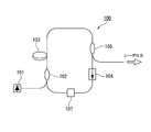
- FIG. 15 shows a typical configuration diagram of this fiber ring laser.
- the fiber ring laser 100 includes a pumping light source 101; a WDM coupler 102 that combines pumping light and laser light; a rare earth-doped optical fiber 103 that is a gain medium; an isolator 104; an optical switch element 107; and an output coupler 105.
- Excitation light emitted from the excitation light source 101 is incident on the rare earth-doped optical fiber 103 via the WDM coupler 102.
- the excitation light incident on the rare earth doped optical fiber 103 is absorbed by the rare earth ions added to the core of the rare earth doped optical fiber and excites the rare earth ions.
- the excited rare earth ions emit spontaneous emission light having a specific wavelength. This spontaneously emitted light propagates through the rare earth-doped optical fiber 103 while being amplified, and is output as ASE (Amplified Spontaneous Emission).
- the WDM coupler 102, the rare earth-doped optical fiber 103, the isolator 104, the output coupler 105, and the optical switch element 107 are connected in a ring shape. Therefore, the ASE passes through these parts and goes around, and is amplified again by the rare earth-doped optical fiber 103. After the ASE is sufficiently amplified, the laser oscillates, and a part thereof is output as laser light through the output coupler 105. At this time, if the optical switch element 107 is operated so as to periodically repeat a low-loss state and a high-loss state, pulses are oscillated and a pulsed laser output is obtained.
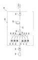
- FIG. 16 shows the configuration of a MOPA optical fiber laser.
- the laser beam output from the MO 100 is incident on the PA 200 via the interstage isolator 316, amplified by the PA 200, and output.
- the PA 200 includes a plurality of excitation light sources 201, an optical coupler 203, a rare earth-doped optical fiber (rare earth-doped double clad fiber) 205, and an isolator 206.
- the same pumping light source 201, rare earth-doped optical fiber 205, and isolator 206 as those used in the MO 100 can be applied.
- As the optical coupler 203 for example, an optical coupler as described in Patent Document 2 is used.
- This optical coupler 203 has a plurality of pumping ports 202 made of a multimode optical fiber and a signal port 204 made of one single mode fiber, which are formed by melting and extending them together.
- One exit port 207 is provided.
- Laser light emitted from the MO 100 is incident from the signal port 204 and is emitted to the core of the rare earth-doped double clad fiber 205 via the optical coupler 203.
- the optical coupler 203 is connected to a pumping port 202 to which a plurality of pumping light sources 201 are connected. The pumping light emitted from each pumping light source 201 is incident on the first cladding of the rare earth-doped double cladding fiber 205 via the optical coupler 203.
- the excitation light incident on the first cladding is absorbed by the rare earth ions added to the core to form an inversion distribution, and stimulated emission occurs. By this stimulated emission, the laser light propagating in the core is amplified and output through the isolator 206.
- the rare earth-doped double clad fiber 205 of the PA 200 is pumped by the pumping light emitted from the pumping light source 201 in a state where the signal light from the MO 100 is not incident, and is inverted.
- the distribution rate is reached, parasitic oscillation occurs and a pulse with a very high spire value is generated.
- the inversion distribution ratio at which parasitic oscillation occurs is determined by the reflectivity between the incident side and the emission side of the rare earth-doped double clad fiber 205.
- a pulse with a very high spire value is emitted from the rare earth-doped double clad fiber 205 toward the optical coupler 203 due to parasitic oscillation.
- the core of the rare earth-doped double clad fiber 205 is damaged by the pulse having a very high spire value, or the pulse reaches the excitation light source 201 or the MO 100 and is damaged.
- the PA 200 outputs from the outside. The reflected light may induce parasitic oscillation.
- the excitation light source 201 of the PA 200 emits excitation light between pulses
- the rare earth-doped double clad fiber 205 is in an excited state. Therefore, ASE is emitted from both ends of the rare earth-doped double clad fiber 205.
- the workpiece is irradiated with ASE from the optical fiber laser. At this time, depending on the surface state of the workpiece, the reflected light reflected by the surface of the workpiece may be incident on the optical fiber laser again.
- this reflected light becomes a seed and oscillation occurs, and a pulse having a very high spire value is emitted from the rare earth-doped double clad fiber 205 toward the optical coupler 203. Then, this pulse reaches the excitation light source 201 and the MO100, and there is a problem that they are damaged.
- the parasitic oscillation occurs, a high inversion distribution rate cannot be realized, and the energy of the pulse that can be output from the PA 200 is limited.
- an isolator is inserted at both ends of the rare earth-doped optical fiber to suppress the reflectance and suppress the parasitic oscillation. Furthermore, by providing a short wavelength pass filter at the exit end of the excitation light source, the ASE emitted from the rare earth-doped optical fiber is prevented from being reflected by the pump laser and entering the rare earth-doped optical fiber again. That is, the optical fiber laser described in Patent Document 3 suppresses parasitic oscillation by suppressing the reflectance on the incident side and the emission side of the rare earth-doped optical fiber as much as possible.
- the optical fiber amplifier is divided into two stages, and an isolator is provided between the stages.
- parasitic oscillation is suppressed by suppressing the gain low.
- the optical fiber laser described in Patent Document 4 does not lead to parasitic oscillation although ASE amplification occurs.
- a resonator is configured by providing fiber Bragg gratings (hereinafter sometimes referred to as FBGs) at both ends of a rare earth-doped double clad fiber, and a multimode is further provided in one FBG. Fiber is connected. Excitation light from the excitation light source is incident on the rare earth-doped double clad fiber through the multimode fiber.
- the core diameter of the multimode fiber is larger than the core diameter of the rare earth-doped double clad fiber.
- the ASE having an unnecessary wavelength that is incident on the multimode fiber without being reflected by the FBG has a low rate of recombination with the core of the rare earth-doped double clad fiber, and parasitic oscillation is suppressed. Even if the parasitic oscillation occurs, the generated pulse is once incident on the multimode fiber. Therefore, even if the ASE is condensed on the excitation light source through the lens, the spot diameter is increased, and thus the excitation light source is hardly damaged.
- the limit of the reflectance is practically limited to about 0.001%. Therefore, in a relatively high-power optical fiber laser that outputs several tens of watts or more, no matter how much reflection is suppressed, this slight reflection or Rayleigh scattering in the fiber becomes a seed, and parasitic oscillation occurs. There is a risk that. Further, with respect to externally reflected light (reflected light on the workpiece surface) generated after laser emission, the intensity of the reflected light is attenuated by the isolator, but cannot be completely cut. Therefore, there is a possibility that parasitic oscillation may be induced by using the slightly remaining reflected light as a seed.
- the present invention has been made in view of the above circumstances, and an object of the present invention is to provide an optical fiber laser in which parasitic oscillation is suppressed and a high-energy pulse can be stably emitted.
- An optical fiber laser of the present invention includes a master oscillator that is a laser oscillator that generates seed light, and an optical amplifier that is connected to a subsequent stage of the master oscillator and amplifies and outputs laser light emitted from the master oscillator.
- An optical fiber laser comprising: a plurality of pumping light sources; and a plurality of pumping light sources, each of which is connected to the plurality of pumping light sources, and the pumping light emitted from the pumping light source is incident thereon.
- An excitation port a signal port to which the laser beam emitted from the master oscillator is incident, an emission beam that emits the excitation light incident from the excitation port and the laser beam incident from the signal port.
- An optical coupler having a port; and an optical fiber connected to the output port; It is a gap fiber; the optical fiber, wavelength horizontal axis, vertical axis in the graph showing the loss, the photonic band gap region has a narrow loss wavelength characteristic than the gain wavelength band.
- the optical fiber is provided with a core portion made of a solid material doped with a rare earth element; a first cladding provided around the core portion; and provided in the vicinity of the core portion of the first cladding; And a periodic structure portion in which a number of high refractive index portions having a higher refractive index than the first cladding are arranged in a periodic structure.
- the maximum relative refractive index difference of the high refractive index portion with respect to the first cladding is preferably 2% to 3%.
- the electric field distribution of light having a wavelength in the photonic band gap region is higher in the core portion than the periodic structure portion; the electric field distribution of light in a wavelength other than the photonic band gap region is the period
- the structure is higher than the core.
- the high refractive index portion preferably contains at least germanium.
- An optical fiber laser of the present invention includes a master oscillator that is a laser oscillator that generates seed light, and an optical amplifier that is connected to a subsequent stage of the master oscillator and amplifies and outputs laser light emitted from the master oscillator.
- An optical fiber laser comprising a power amplifier, wherein the master oscillator is connected to the excitation light source, and a WDM coupler that combines the excitation light from the excitation light source and the laser light;
- An optical fiber connected to the WDM coupler, an output coupler connected to the optical fiber, and an isolator; the WDM coupler, the optical fiber, the output coupler, and the isolator are sequentially ring-shaped.
- the optical fiber has a photonic bar in a graph in which the horizontal axis indicates the wavelength and the vertical axis indicates the loss amount. -Gap region has a narrow loss wavelength characteristic than the gain wavelength band.
- An optical fiber laser of the present invention includes a master oscillator that is a laser oscillator that generates seed light, and an optical amplifier that is connected to a subsequent stage of the master oscillator and amplifies and outputs laser light emitted from the master oscillator.
- the power amplifier is the power amplifier described in (1) above; the master oscillator is the master oscillator described in (6) above.
- the optical fiber laser described in (1) above According to the optical fiber laser described in (1) above, ASE at an unnecessary wavelength that causes parasitic oscillation can be efficiently removed. Therefore, it is possible to lengthen the time until parasitic oscillation occurs. Therefore, more energy can be stored than the conventional optical fiber laser. As a result, when the pulsed light is amplified, high gain amplification can be performed, and high energy pulse output that cannot be output by a conventional optical fiber laser becomes possible. Further, even in the condition where the parasitic oscillation has conventionally occurred, the optical fiber laser of the present invention does not generate the parasitic oscillation. Therefore, damage caused to each component of the optical fiber laser by this parasitic oscillation can be suppressed.
- optical fiber laser of the present invention unnecessary light is removed in a wavelength distribution, so that the unnecessary light does not become high intensity. Therefore, the unnecessary light has little influence on the optical component, and cooling is easy. Therefore, an optical fiber laser that can be used stably over a long period of time can be provided. In addition, similar effects can be obtained with the optical fiber laser described in (6) above.
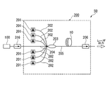
- FIG. 1A is a diagram schematically showing an optical fiber laser according to the first embodiment of the present invention.
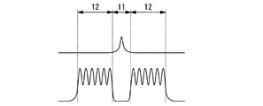
- FIG. 1B is a diagram showing loss wavelength characteristics of the optical fiber used in the optical fiber laser of the same embodiment.
- FIG. 2A is a cross-sectional view schematically showing an optical fiber used in the optical fiber laser of the embodiment.
- FIG. 2B is a diagram showing a refractive index profile of the optical fiber used in the optical fiber laser of the same embodiment.
- FIG. 2C is a diagram schematically showing the electric field distribution of the optical fiber used in the optical fiber laser of the embodiment.
- FIG. 3A is a cross-sectional view schematically showing an optical fiber used in an optical fiber laser according to the second embodiment of the present invention.
- FIG. 3B is a diagram showing a refractive index profile of the optical fiber used in the optical fiber laser of the embodiment.
- FIG. 3C is a diagram schematically showing an electric field distribution of the optical fiber used in the optical fiber laser of the embodiment.
- FIG. 4A is a cross-sectional view schematically showing an optical fiber used in an optical fiber laser according to the third embodiment of the present invention.
- FIG. 4B is a diagram showing a refractive index profile of the optical fiber used in the optical fiber laser of the embodiment.
- FIG. 4C is a diagram schematically showing an electric field distribution of the optical fiber used in the optical fiber laser of the embodiment.
- FIG. 5A is a cross-sectional view schematically showing an optical fiber used in an optical fiber laser according to the fourth embodiment of the present invention.
- FIG. 5B is a diagram showing a refractive index profile in the A-A ′ direction of the optical fiber used in the optical fiber laser of the same embodiment.
- FIG. 5C is a diagram schematically showing the electric field distribution in the B-B ′ direction of the optical fiber used in the optical fiber laser of the embodiment.
- FIG. 5D is a diagram showing a refractive index profile in the A-A ′ direction of the optical fiber used in the optical fiber laser of the embodiment.
- FIG. 5E is a diagram schematically showing the electric field distribution in the B-B ′ direction of the optical fiber used in the optical fiber laser of the embodiment.
- FIG. 6A is an electron micrograph of a cross section of the optical fiber used in the optical fiber laser according to the fifth embodiment of the present invention.
- FIG. 6B is a diagram showing a refractive index profile of the optical fiber used in the optical fiber laser of the same embodiment.
- FIG. 6C is a diagram schematically showing the electric field distribution in the X-axis direction of the optical fiber used in the optical fiber laser of the embodiment.
- FIG. 6D is a diagram schematically showing an electric field distribution in the Y-axis direction of the optical fiber used in the optical fiber laser of the embodiment.
- FIG. 7 is a diagram schematically showing an optical fiber laser according to the sixth embodiment of the present invention.
- FIG. 8 is a diagram observing the time from when the excitation light is input to when the parasitic oscillation occurs using the optical fiber laser of Example 1.
- FIG. 9 is a diagram observing the time from when the excitation light is input to when the parasitic oscillation occurs using the optical fiber laser of the second embodiment.
- FIG. 10 is a diagram observing the time from when the excitation light is input until the parasitic oscillation occurs using the optical fiber laser of the comparative example.
- FIG. 11 is a diagram schematically showing an apparatus used for measuring a transmission spectrum of the optical fiber used in Example 4.
- FIG. 12 is a diagram showing a transmission spectrum of the optical fiber used in Example 4.
- FIG. 13A is a diagram when the ASE spectrum of the optical fiber laser of Example 4 is measured.
- FIG. 13B is a diagram when the ASE spectrum of the optical fiber laser of Example 4 is measured.
- FIG. 14 is a schematic view of a typical optical fiber laser of the MOPA system.
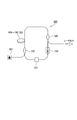
- FIG. 15 is a diagram schematically showing a general MO.
- FIG. 16 is a diagram schematically showing a general PA and an optical fiber laser.
- FIG. 1A is a configuration diagram schematically showing an optical fiber laser 50 according to a first embodiment of the present invention.
- FIG. 1B shows the loss wavelength characteristics of the optical fiber 10 used in the optical fiber laser 50 of the present embodiment.
- the optical fiber laser of the present embodiment is connected to a master oscillator (hereinafter also referred to as MO) 100 of a laser oscillator that generates seed light and a subsequent stage of this MO, similarly to the optical fiber laser shown in FIG.
- MO master oscillator
- PA power amplifier
- the MO 100 for example, a fiber ring laser 100 shown in FIG. 15 can be used.
- the output side of the MO 100 is connected to the PA 200 via an interstage isolator 316.
- the PA 200 includes a plurality of excitation light sources 201; an excitation port 202 that is connected to each of the plurality of excitation light sources 201 and into which the excitation light emitted from the excitation light source 201 is incident; and a laser beam emitted from the master oscillator 100 And an optical coupler 203 having an output port 205 for emitting each pump light incident from the pump port 202 and laser light incident from the signal port 204;
- the optical fiber 10 connected to 205 is schematically configured. Laser light emitted from the MO 100 enters the PA 200 from the signal port 204 and enters the core of the optical fiber 10 via the optical coupler 203.
- the optical fiber 10 includes a core and a clad surrounding the core. Rare earth ions are added to the core.
- the excitation light emitted from each excitation light source 201 is incident on the first cladding of the optical fiber 10 via the optical coupler 203.
- the excitation light incident on the first cladding of the optical fiber 10 is absorbed by the rare earth ions added to the core to form an inversion distribution, and stimulated emission occurs.
- This stimulated emission amplifies the laser beam propagating in the core.
- This amplified laser beam is output via the isolator 206. That is, the laser beam output from the MO 100 is incident on the PA 200 via the interstage isolator 316, amplified by the PA 200, and output. Details will be described below.
- optical coupler 203 for example, a conventionally known optical coupler as disclosed in Patent Document 2 is used, and a plurality of pumping ports 202 made of a multimode optical fiber and a signal port made of one single mode fiber. 204 on one side. On the other side of the optical coupler 203, there is an emission port 205 that emits each excitation light incident from the excitation port 202 and laser light incident from the signal port 204.
- a laser diode (LD) or the like is preferably used, but is not limited thereto.
- the optical fiber 10 is a photonic bandgap fiber and has the loss characteristics shown in FIG. 1B.
- the horizontal axis of the graph in FIG. 1B indicates the wavelength of light, and the vertical axis indicates the amount of light loss.
- the photonic band gap exists within the gain wavelength band of optical amplification by rare earth ions added to the core. Furthermore, this photonic band gap is a narrower wavelength band than the gain wavelength band. In addition to this wavelength band relationship, the structure described later is determined so that the photonic band gap includes the oscillation wavelength of the optical fiber laser 50.
- the photonic band gap is formed only in the oscillation wavelength band to be guided among the spontaneous emission light over a wide wavelength band generated when the rare earth ions added to the core part are excited. For this reason, the light of the oscillation wavelength is confined and propagated in the core portion of the optical fiber 10, and the spontaneous emission light in the wavelength band other than the oscillation wavelength band is emitted to the clad without being confined in the core portion. That is, since spontaneous emission light other than the oscillation wavelength band that becomes the seed of parasitic oscillation is emitted from the core portion to the cladding, parasitic oscillation can be suppressed. In particular, parasitic oscillation is likely to occur at a wavelength at which the gain of the rare earth-doped optical fiber is maximized.
- the optical fiber 10A (10) used in the optical fiber laser 50 of the present embodiment has a cross-sectional structure shown in FIG. 2A, for example.
- the optical fiber 10A includes a core portion 11 made of a solid material doped with a rare earth element; a first cladding 13 provided around the core portion 11; and a vicinity of the core portion 11 of the first cladding 13.
- crud 13 is comprised roughly from the periodic structure part 12 arrange
- a fluorine-based ultraviolet curable resin layer having a negative relative refractive index difference with respect to pure quartz may be provided on the outer periphery of the first cladding 13.
- the optical fiber 10A has a completely solid structure with no holes. Therefore, when the optical fiber 10A of the present embodiment is fusion-spliced with another optical fiber, the holes are not crushed and the structure is not changed. Therefore, fusion splicing can be performed with low loss.
- Each part of the core part 11, the periodic structure part 12, and the first cladding 13 of the optical fiber 10A is made of pure silica glass or quartz glass obtained by adding a refractive index adjusting dopant such as fluorine or germanium. It is composed of In the optical fiber 10 of this embodiment, the material of each part is not limited only to this illustration.
- the core part 11 is formed by adding rare earth ions to pure quartz.
- the refractive index of the core 11 is preferably the same as that of pure quartz.
- Examples of rare earth ions to be added include ytterbium (Yb), erbium (Er), thulium (Tm), neodymium (Nd), praseodymium (Pr), etc., and these may be used alone or May be mixed in a desired ratio.
- high refractive index portions 14 In the vicinity of the core portion 11 of the first cladding 13, a large number of high refractive index regions (high refractive index portions 14) having a small circular cross section to which germanium (Ge) or the like is added are arranged.
- the high refractive index portions 14 are arranged in a triangular lattice-like periodic structure to form the periodic structure portion 12.
- the triangular lattice shape means the first high refractive index portion 14a, the second high refractive index portion 14b adjacent to the first high refractive index portion 14a, and the first high refractive index portion.
- 14a and the third high refractive index portion 14c adjacent to the second high refractive index portion 14b form an equilateral triangle.
- a photonic band having a desired wavelength band can be formed by adjusting the diameter and period of the high refractive index portion 14, the interval between the high refractive index portions 14, and the relative refractive index difference with respect to pure quartz glass.
- the diameter of the high refractive index portion 14 is 3 ⁇ m to 5 ⁇ m
- the interval between the high refractive index portions 14 is 5 ⁇ m to 10 ⁇ m
- the period of the high refractive index portion 14 is 3 to 6 layers.
- the maximum relative refractive index difference with respect to the first cladding is 2% to 3%.
- the region of the first cladding 13 where the periodic structure portion 12 is disposed occupies a larger proportion than the region of the first cladding 15 where the periodic structure portion 12 is not disposed.
- the core portion 11 having the same refractive index as that of pure quartz is arranged at the center, and Ge or the like is added to the periphery thereof to refract more than the core portion 11.
- the periodic structure part 12 with a high rate is arranged. Therefore, the refractive index profile of the optical fiber 10A is shown in FIG. 2B. As shown in FIG. 2B, the refractive indexes of the core portion 11 and the first cladding 13 are equal, and the refractive index of the periodic structure portion 12 (the refractive index of each high refractive index portion 14) is the same as that of the core portion 11 and the first cladding portion 13. The refractive index is higher than that of the first cladding 13.
- the light in the photonic band gap wavelength region is confined in the low refractive index region, that is, the core portion 11.
- the light in the wavelength region of the photonic band gap has an electric field concentrated on the core portion 11 and guided through the core portion 11 as shown in the upper part of FIG. 2C. That is, for light in the wavelength range of the photonic band gap, the low refractive index region functions as a core portion, and the high refractive index region (periodic structure portion 12 including the high refractive index portion 14) functions as a cladding.
- the optical fiber laser 50 of the present embodiment by using the optical fiber 10A, ASE at an unnecessary wavelength, which causes parasitic oscillation, can be efficiently removed, and the time until parasitic oscillation occurs is reduced. Can be long. Therefore, more energy can be stored than the conventional optical fiber laser. Therefore, when amplifying pulsed light, high gain amplification can be performed, and high energy pulse output that cannot be output by a conventional optical fiber laser becomes possible.
- parasitic oscillation does not occur even under conditions where parasitic oscillation has conventionally occurred. Therefore, it is possible to suppress damage that occurs in each component of the fibre laser. Furthermore, since unnecessary light is removed in a wavelength distribution, the unnecessary light does not become high intensity. Therefore, the unnecessary light has little influence on the optical component, and cooling of each component constituting the optical fiber laser is facilitated. Therefore, an optical fiber laser that can be used stably over a long period of time is obtained.
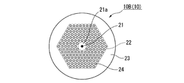
- FIG. 3A is a cross-sectional view schematically showing an optical fiber 10B (10) mounted on the optical fiber laser according to the second embodiment.
- FIG. 3B is a diagram showing a refractive index profile of the optical fiber 10B used in the present embodiment.
- FIG. 3C is a diagram showing an electric field distribution of the optical fiber 10B used in the present embodiment.
- the optical fiber laser of this embodiment is different from the optical fiber laser of the first embodiment in that it has a cross section shown in FIG. 3A and has a refractive index profile shown in FIG. 3B and an electric field distribution shown in FIG. 3C. This is a point using the fiber 10B.
- the refractive index profile of the optical fiber 10B according to the present embodiment also includes a high refractive index portion (core portion 21) in the region 21a.
- light having a wavelength in the photonic band gap region is a region having a high refractive index (periodic structure) in which the high refractive index portion 24 is disposed, as in the optical fiber 10A of the first embodiment. Part 22) cannot be guided. For this reason, the light is guided inside the periodic structure portion 22.
- a core portion 21 having a refractive index higher than that of pure quartz is formed at the center. Therefore, as shown in the upper part of FIG. 3C, the light having a wavelength in the photonic band gap region concentrates more strongly on the core portion 21 than the optical fiber 10 ⁇ / b> A used in the first embodiment.
- the optical fiber 10B of the present embodiment is formed by rotating an optical fiber preform during spinning. Therefore, the periodic structure portion 22 is twisted in a spiral shape in the length direction of the fiber. Therefore, the optical fiber preform is substantially bent in the longitudinal direction. Therefore, loss of light occurs in the optical fiber 10B due to macro vent or micro vent. In the optical fiber 10B used in the present embodiment, the loss of light gives loss to light in a wavelength region other than the photonic band gap guided through the core portion 21, and removes this light. On the other hand, since the core part 21 is in the center of the optical fiber 10 ⁇ / b> B, twist does not appear in the shape of the core part 21.
- the helical pitch may be adjusted as appropriate so as to give a loss to light in a desired wavelength range.
- the optical fiber 10B As described above, by using the optical fiber 10B, it is possible to effectively remove light having a wavelength other than the photonic band gap region. Therefore, in the optical fiber laser using this optical fiber 10B, the ASE at the unnecessary wavelength that causes the parasitic oscillation is removed, and the time until the parasitic oscillation occurs can be lengthened. Therefore, the same effect as the optical fiber laser 50 of the first embodiment described above can be obtained.
- the refractive index of the core portion 21 is higher than that of the optical fiber 10A of the first embodiment. Therefore, the electric field of light having a wavelength in the photonic band gap region is stronger in the core portion 21 than in the optical fiber 10A of the first embodiment. As a result, in the optical fiber laser of the present embodiment, the laser light propagating in the core portion 21 can be amplified more greatly, and higher-energy pulse output is possible than in the optical fiber laser of the first embodiment.
- the optical fiber 10B used in the present embodiment loss was given to light in a wavelength region other than the photonic band gap guided through the core portion 21 by the macro vent or the micro vent, but in the periodic structure portion 22, An additive that absorbs or scatters light having a fluorescence wavelength of Yb may be added to give loss to light in a wavelength region other than the photonic band gap. Further, if the return loss on the incident side and the outgoing side of the optical fiber 10B is larger than the gain received by the optical fiber 10B, parasitic oscillation can be suppressed. The light guided through the optical fiber 10B undergoes two losses when emitted from the optical fiber 10B and when incident. Therefore, when the light emitted from the optical fiber 10B or incident, the loss received by the light of the wavelength other than the photonic band gap region is larger than half of the gain received when guiding the optical fiber 10B, Parasitic oscillation can be suppressed.
- FIG. 4A is a cross-sectional view schematically showing an optical fiber 10C (10) mounted on the optical fiber laser according to the third embodiment.
- FIG. 4B is a diagram showing a refractive index profile of the optical fiber 10C used in the present embodiment.
- FIG. 4C is a diagram showing an electric field distribution of the optical fiber 10C used in the present embodiment.
- the optical fiber laser of this embodiment is different from the optical fiber laser of the first embodiment in that it has a cross section shown in FIG. 4A and has a refractive index profile shown in FIG. 4B and an electric field distribution shown in FIG. 4C. This is a point using the fiber 10C.
- the first layer and the second layer (near the core) inside the periodic structure portion 12 of the first embodiment are eliminated, and a region 31a made of pure quartz is formed. Is formed.
- this region 31a Al, Ge or the like is doped in addition to Yb, and a core portion 31 having a refractive index higher by about 0.1% to 0.5% than that of surrounding pure quartz is formed. Therefore, as shown in FIG. 4B, the refractive index profile of the optical fiber 10C of the present embodiment also includes a portion having a high refractive index in the core portion 31 of the region 31a.
- the intervals between the high refractive index portions 34 are narrowed by about 10% to 20%, and are concentrated near the core portion 31.
- the diameter of the high refractive index portion 34 is about 30% to 40% larger than that of the first embodiment.
- the relative refractive index difference between the high refractive index portion 34 and pure silica glass is the same as that of the optical fibers of the first and second embodiments.
- the number of layers of the periodic structure portion 34 of the optical fiber 10 of the present embodiment is smaller than that of the first embodiment, for example, about three layers. Since the diameter of the first clad 33 is the same as that of the first embodiment, the region 35 where the periodic structure portion 32 of the first clad 33 is not disposed is wider than that of the first embodiment.
- a fluorine-based ultraviolet curable resin layer 36 having a negative relative refractive index difference with respect to pure quartz (for example, about ⁇ 5%) is disposed.
- the first clad 33 made of pure silica glass forms the second core
- the fluorine-based ultraviolet curable resin 36 forms the second clad, and is a double-mode guided multimode. It has a clad structure.
- the refractive index profile and electric field distribution are the same as in the second embodiment, and are as shown in FIGS. 4B and 4C, respectively. That is, as shown in the upper part of FIG. 4C, the light having a wavelength in the photonic band gap region concentrates more strongly on the core portion 31 than the optical fiber 10A used in the first embodiment. As shown in the lower part of FIG. 4C, light having a wavelength other than the photonic band gap region has a slight electric field in the core portion 31 in addition to the periodic structure portion 32 of the optical fiber 10C. Waveguide becomes possible. Similarly to the optical fiber 10B used in the second embodiment, light other than the photonic band gap wavelength region is removed from the optical fiber 10C used in the present embodiment by the macro vent or the micro vent.
- the core portion 31 is also similar to the optical fiber 10B of the second embodiment, and light having a wavelength in the photonic band gap region does not cause light loss due to the above macro vent or micro vent, and the core portion 11 Has not been removed from.
- the optical fiber 10C As described above, by using the optical fiber 10C, it is possible to effectively remove light having a wavelength other than the photonic band gap region. Therefore, in the optical fiber laser using this optical fiber 10C, the ASE at the unnecessary wavelength that causes the parasitic oscillation is removed, and the time until the parasitic oscillation occurs can be lengthened.
- the light of the second embodiment described above The same effect as the fiber laser can be obtained.
- FIG. 5A is a cross-sectional view schematically showing an optical fiber 10D (10) mounted on an optical fiber laser according to the fourth embodiment.
- FIG. 5B is a refractive index profile in the AA ′ direction of the optical fiber 10D.
- FIG. 5C is a refractive index profile in the BB ′ direction of the optical fiber 10D.
- FIG. 5D shows an electric field distribution in the AA ′ direction of the optical fiber 10D.
- FIG. 5E shows an electric field distribution in the BB ′ direction of the optical fiber 10D.
- the optical fiber laser of the present embodiment is different from the optical fiber laser of the first embodiment in that it has the cross section shown in FIG. 5A and the refractive index profile shown in FIGS. 5B and 5C and the electric field distribution shown in FIGS. 5D and 5E. This is a point using an optical fiber 10D having the following.
- the relative refractive index difference of the core portion 41 with respect to pure quartz glass, the interval and diameter between the high refractive index portions 44, the relative refractive index difference, and the like are used in the third embodiment. This is the same as the optical fiber 10C.
- the optical fiber 10D of the present embodiment has a higher number of layers of the high refractive index portion 44 than the optical fiber 10C of the third embodiment, and forms one linear region 47 from the core portion 41 toward the outer periphery of the optical fiber. Is not provided with the high refractive index portion 44.
- the refractive index profile and the electric field distribution are as shown in FIGS. 5B to 5E, respectively. That is, as shown in the upper part of FIGS. 5D and 5E, the light having a wavelength in the photonic band gap region concentrates more strongly on the core portion 41 than the optical fiber 10A used in the first embodiment. Since light having a wavelength other than the photonic band gap region has a slight electric field in the core portion 41 in addition to the periodic structure portion 42 of the optical fiber 10D as shown in the lower part of FIGS. 5D and 5E, the optical fiber It becomes possible to guide in 10D.
- the optical fiber 10D used in the present embodiment also emits light other than the photonic bandgap wavelength region guided through the core portion 31 by the macro vent or the micro vent. Has been removed.
- the core portion 41 is also similar to the optical fiber 10B of the second embodiment, and light having a wavelength in the photonic band gap region does not cause light loss due to the macro vent or micro vent. Not removed from.
- the optical fiber 10D used in the present embodiment has a higher number of layers of the high refractive index portions 44 than the optical fiber 10C used in the third embodiment. Therefore, more light with a wavelength other than the photonic band gap region exists in the periodic structure portion 42. As a result, the parasitic oscillation suppression effect can be further enhanced. Further, even if the number of layers of the high refractive index portion 44 is increased and the light confinement effect by the photonic band gap becomes strong, a higher order mode is emitted through the region 47 where the high refractive index portion 44 is not disposed. Therefore, stable operation is possible in the basic mode.
- the optical fiber laser of this embodiment using this optical fiber 10D can suppress the occurrence of parasitic oscillation more effectively than the optical fiber laser of the third embodiment, and can operate stably in the basic mode. It becomes.
- FIG. 6A is an electron micrograph of a cross section of the optical fiber 10E (10) mounted on the optical fiber laser according to the fifth embodiment.
- FIG. 6B is a diagram showing a refractive index profile of the optical fiber 10E.
- FIG. 6C is a diagram illustrating an electric field distribution in the X-axis direction of the optical fiber 10E.
- FIG. 6D is a diagram illustrating an electric field distribution in the Y-axis direction of the optical fiber 10E.
- the optical fiber laser of the present embodiment is different from the optical fiber laser of the first embodiment in that it has a cross section shown in FIG. 6A and has a refractive index profile shown in FIG. 6B and electric field distributions shown in FIGS. 6C and 6D.
- the optical fiber 10E is used.
- the high refractive index portion 64 is arranged only in one straight line from the core portion 61 toward the outer periphery of the optical fiber.
- the high refractive index portion 64 is the same as the optical fiber 10A used in the first embodiment. Therefore, the optical fiber 10E has a refractive index profile as shown in FIG. 6B.
- the upper part of FIG. 6B is the refractive index profile in the X-axis direction shown in FIG. 6A.
- FIG. 6B is a refractive index profile in the Y-axis direction shown in FIG. 6A.
- light in the photonic band gap wavelength region is a photo formed by pure quartz arranged in the X-axis direction and a periodic structure formed by a high refractive index portion doped with Ge. Due to the nick band gap, the high refractive index portion cannot be guided and is confined in the core region 51. In the Y-axis direction, the light is confined in the core region 51 and guided by a refractive index difference between pure quartz and a low refractive index portion doped with fluorine (F).
- F fluorine
- the light outside the photonic band gap wavelength region is caused by the difference in refractive index between pure quartz and the low refractive index portion doped with F in the Y-axis direction as in the photonic band gap wavelength region.
- the core region 51 most of the electric field distribution is guided in the high refractive index portion instead of the core region 51 due to its periodic structure in the X direction.
- the optical fiber 10E As described above, by using the optical fiber 10E, it is possible to effectively remove light having a wavelength other than that of the photonic band gap region. Therefore, in the optical fiber laser using the optical fiber 10E, the ASE at the unnecessary wavelength that causes the parasitic oscillation is removed, and the time until the parasitic oscillation occurs can be lengthened. The same effect as that of the fiber laser 50 can be obtained. Furthermore, in the optical fiber 10E of the present embodiment, the refractive index structure in the X-axis direction and the Y-axis direction are greatly different, so the core has birefringence. By having birefringence, the light guided in the core has a different refractive index depending on its polarization component, and exhibits optically different characteristics.
- the polarization component in the X-axis direction is more susceptible to bending loss than the polarization component in the Y-axis direction. Therefore, only the polarization component in the X-axis direction can be selectively amplified and output by bending the optical fiber with a diameter that causes bending loss only in the Y-axis direction according to the oscillation wavelength of the laser. That is, it is possible to output single-polarized laser light without reducing efficiency by simply bending the optical fiber.
- an FBG is provided in the core portion over the entire length, and the rare earth-doped optical fiber is wound with a predetermined diameter, thereby giving a loss on the long wavelength side of the signal wavelength, or
- the gain is the same as in the present invention. It is also possible to give a loss to the wavelength band.
- FIG. 7 is a view schematically showing an optical fiber laser 100 according to the sixth embodiment.
- the optical fibers 10A to 10E used in the first to fifth embodiments described above can be applied to the MO optical fiber. That is, the WDM coupler 102, the optical fiber 10, the output coupler, and the isolator 104, which are connected to the pumping light source 101 and combine the pumping light and the laser light from the pumping light source 101, are sequentially connected in a ring shape.
- the optical fiber 10 is the above-described photonic bandgap fibers 10A to 10E.
- the optical fiber 10 used in the first to fifth embodiments is applicable to both PA and MO, without being limited to only PA or MO. By applying to both, parasitic oscillation can be suppressed more effectively, and an optical fiber laser with higher output can be obtained.
- Example 1 An optical fiber laser having the configuration shown in FIG. 1A was configured.
- an optical fiber having a cross-sectional structure shown in FIG. 2A and characteristics shown in FIGS. 2B and 2C was produced as a photonic bandgap fiber.
- Yb ions were added to the core part.
- the wavelength range where the parasitic oscillation is most likely to occur that is, the vicinity of the maximum gain wavelength range of 1030 nm to 1050 nm of the optical fiber doped with Yb ions is not included in the band gap region, and the signal wavelength of 1064 nm is the band gap region.
- FIG. 1 An optical fiber laser having the configuration shown in FIG. 1A was configured.
- an optical fiber having a cross-sectional structure shown in FIG. 2A and characteristics shown in FIGS. 2B and 2C was produced as a photonic bandgap fiber.
- Yb ions were added to the core part.
- the wavelength range where the parasitic oscillation is most likely to occur that is, the vicinity of the
- Yb ions were added to pure quartz glass to produce a core portion having a relative refractive index difference ⁇ c of 0% and a diameter d of 7.0 ⁇ m with respect to pure quartz glass.
- This core portion was covered with a first clad made of pure quartz glass and having a diameter of 125 ⁇ m.
- germanium was added to pure quartz glass to produce a plurality of high refractive index portions.
- the high refractive index portions were arranged in a triangular lattice shape with a distance of 7.0 ⁇ m from each other, thereby forming a periodic structure portion composed of seven high refractive index portions.
- Each high refractive index portion has a maximum relative refractive index difference ⁇ h of 2.8% with respect to pure quartz glass and a diameter dh of 3.5 ⁇ m.
- the core absorption of this manufactured optical fiber was 1200 dB / m at a wavelength of 976 nm.
- An optical coupler having a rare earth-doped double clad fiber having a core diameter of 7 ⁇ m and a clad diameter of 125 ⁇ m was used as an output port so that the connection loss with the Yb-doped double clad fiber was reduced.
- As the excitation port six multimode fibers having a core diameter of 105 ⁇ m and an NA of 0.15 were used.
- As the signal port a single mode fiber having a core diameter of 7 ⁇ m and an NA of 0.14 was used.
- As the excitation light source six semiconductor lasers having an oscillation wavelength of 915 nm and a maximum output of 5 W were used.
- the pumping light source was driven without a signal from the master oscillator, pumping light was emitted, and the rare earth-doped double clad fiber was pumped with a pumping power of 30 W. Thereafter, the time from when the excitation light was input until the parasitic oscillation occurred was measured. The result is shown in FIG. As shown in FIG. 8, in the optical fiber laser of Example 1 using the photonic bandgap fiber shown in FIGS. 2A to 2C, no parasitic oscillation occurred even when excited for about 30 ⁇ s. When excitation was continued for a long time, parasitic oscillation was observed at about 70 ⁇ s.
- Example 2 An optical fiber laser was used in the same manner as in Example 1 except that the PBGF shown in FIGS. 3A to 3C was used instead of the photonic bandgap fiber (hereinafter sometimes referred to as PBGF) used in Example 1.
- PBGF photonic bandgap fiber
- the PBGF of the present example is made of pure quartz by eliminating the first layer (the innermost first layer) of the periodic structure of the PBGF of Example 1, and at this center, pure quartz glass is doped with ytterbium oxide. It was made to function as an amplification medium. Furthermore, by adding aluminum oxide to the center, a core portion having a diameter of 6 ⁇ m was formed with a relative refractive index difference from pure quartz of 0.3%.
- the high refractive index portion has a relative refractive index difference of 2.6% with respect to pure quartz glass.
- the interval between the high refractive index portions was 6 ⁇ m, and the diameter was 4.8 ⁇ m.
- the diameter of the first cladding was set to 125 ⁇ m, and a fluorine-based ultraviolet curable resin layer having a relative refractive index difference of ⁇ 0.5% from that of pure quartz glass was disposed around the first cladding.
- the PBGF used in this example is manufactured by applying a twist of one rotation per 5 mm.
- the PBGF used in this example has a double clad structure in which the first clad made of pure quartz is used as the second core, and the fluorine-based ultraviolet curable resin layer is used as the second clad for multimode wave guiding.
- the core absorption is 1200 dB / m at a wavelength of 976 nm.
- this optical fiber laser was measured for the time from when the excitation light was input until the parasitic oscillation occurred. The result is shown in FIG. As shown in FIG. 9, in the optical fiber laser of Example 2 using PBGF shown in FIGS. 3A to 3C, parasitic oscillation did not occur even when excited for about 30 ⁇ s. When excitation was continued for a long time, parasitic oscillation was observed at about 70 ⁇ s.
- a conventional rare earth-doped optical fiber having a double clad structure was used.
- this optical fiber Yb ions are added to the core, the core diameter is 6 ⁇ m, the first cladding diameter is 125 ⁇ m, and the core absorption is 1200 dB / m at a wavelength of 976 nm.
- this optical fiber laser was measured for the time from when the excitation light was input until the parasitic oscillation occurred. The result is shown in FIG. As shown in FIG. 10, in the optical fiber laser of the comparative example using the conventional optical fiber, parasitic oscillation was observed in about 30 ⁇ s.
- the optical fiber laser of the present invention uses the above-described PBGF 10 to increase the time required for parasitic oscillation more than twice as compared with the conventional optical fiber laser shown in the comparative example.
- the gain of the rare earth-doped optical fiber immediately before amplifying the pulse is larger than that of a conventional fiber laser, and a higher energy pulse can be output.
- the pulse output from the PA had a pulse width of 50 ns and a peak power of 3 kW (pulse energy was 0.15 mJ).
- the pulse width was 50 ns and the peak power was 8 kW (pulse energy was 0.4 mJ). Therefore, according to the optical fiber laser of the present invention, by using the above-described PBGF, a high energy pulse output that cannot be realized by a conventional optical fiber laser is possible.
- Parasitic oscillation occurs when the return loss on the incident side and the exit side of the PBGF becomes larger than the gain received by the PBGF. That is, parasitic oscillation can be suppressed if the return loss on the incident side and the exit side of the PBGF is larger than the gain received by the PBGF.
- the reflection attenuation amount on the incident side and the emission side of the PBGF varies depending on the circuit configuration of the optical fiber amplifier, and in some cases, the reflection attenuation amount may be almost zero.
- the light having a wavelength other than the photonic band gap region receives a large loss because the electric field is almost distributed in the periodic structure.
- the light guided through the PBGF undergoes two losses when exiting the PBGF and when entering the PBGF. Therefore, when light is emitted from or incident on the PBGF, if the loss received by light of wavelengths other than the photonic band gap region is greater than half of the gain received when guiding the PBGF, parasitic oscillation is suppressed. it can. Thus, when the connection loss on the incident side and the emission side was measured in the PBGF of Comparative Example 2, both were about 15 dB. Therefore, it is considered that parasitic oscillation can be suppressed by making the connection loss on the incident side and the emission side of PBGF larger than 15 dB.
- Example 3 In the PBGF of Comparative Example 2, only the number of layers of the PBGF periodic structure was increased so that more components could be guided through the periodic structure, and a PBGF that could secure a connection loss of about 25 dB on the incident side and the outgoing side was manufactured. .
- the PBGF has a core portion diameter of 6 ⁇ m, a first cladding diameter of 125 ⁇ m, and a core absorption of 1200 dB / m at a wavelength of 976 nm.
- an optical fiber laser was constructed in the same manner as in Example 1, and this was designated as the optical fiber laser of Example 3. In the same manner as in Example 1, this optical fiber laser was measured for the time from when the excitation light was input until the parasitic oscillation occurred. As a result, parasitic oscillation was observed at about 60 ⁇ s.
- PBGF shown in FIG. 6A was produced.
- the core part is the same as in the first embodiment.
- the intervals between the high refractive index portions were 7.3 ⁇ m, the diameter was 3.7 ⁇ m, and the relative refractive index difference from the pure quartz glass was 2.8%.
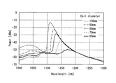
- this PBGF was taken out 1 m at a time and wound once each so that the diameter became 100 mm, 80 mm or 60 mm.
- the white light source was irradiated to the end surface of each PBGF, the core part was excited, and the transmission spectrum was measured. The result is shown in FIG.
- the PBGF used in this example can remove the ASE light having a wavelength of 1000 to 1100 nm guided through the core part by the filter effect by the photonic band gap and can stably oscillate light having a wavelength of about 1100 nm or more.
- the smaller the diameter of the optical fiber wound the more the obtained graph shifted to the longer wavelength side. Therefore, by changing the diameter when winding the optical fiber, the light for amplification with rare earth ions can be easily obtained.
- the gain profile of the fiber could be controlled.
- the gain profile of the rare-earth-ion-doped amplification optical fiber can be controlled while maintaining the ASE light removal effect.
- FIGS. 13A and 13B show the results when six semiconductor lasers having an oscillation wavelength of 915 nm and a maximum output of 0.45 W are used as excitation light sources.
- FIG. 13B shows the results when six semiconductor lasers having an oscillation wavelength of 915 nm and a maximum output of 2.2 W are used as excitation light sources.
- the present invention can be applied to an optical fiber laser capable of stably emitting a high-energy pulse.
Abstract
Description
本願は、2008年02月19日に、日本国に出願された特願2008-038005号に基づき優先権を主張し、その内容をここに援用する。 The present invention relates to an optical fiber laser, and more particularly to an optical fiber laser in which parasitic oscillation is suppressed by using a photonic band gap fiber adjusted so as to be a photonic band gap region only in a signal wavelength region.
This application claims priority based on Japanese Patent Application No. 2008-038005 filed in Japan on February 19, 2008, the contents of which are incorporated herein by reference.
MOPA方式では、マスターオシレータ(以下、MOということがある)100の後段にパワーアンプ(以下、PAということがある)200が接続された構成となっている。この構成だと、MO100から出力された微弱なパルス光がPA200で増幅され、高出力のレーザ光がPA200から出射される。1段のPA200では十分な出力が得られない場合には、所望の出力が得られるように、多段にPA200が接続される。 FIG. 14 shows a schematic diagram of a typical high-power optical fiber laser called the MOPA system.
The MOPA system has a configuration in which a power amplifier (hereinafter also referred to as PA) 200 is connected to a subsequent stage of a master oscillator (hereinafter also referred to as MO) 100. With this configuration, the weak pulse light output from the MO 100 is amplified by the
図15に、このファイバリングレーザの代表的な構成図を示す。
ファイバリングレーザ100は、励起光源101と;励起光とレーザ光を合波するWDMカプラ102と;利得媒質である希土類添加光ファイバ103と;アイソレータ104と;光スイッチ素子107と;出力カプラ105と;からなる。励起光源101から出射された励起光は、WDMカプラ102を介して希土類添加光ファイバ103へと入射される。希土類添加光ファイバ103に入射された励起光は、希土類添加光ファイバのコアに添加された希土類イオンに吸収され、希土類イオンを励起させる。励起状態となった希土類イオンは、特定の波長の自然放出光を放出する。この自然放出光は、増幅されながら希土類添加光ファイバ103内を伝搬し、ASE(Amplified Spontaneous Emission)として出力される。WDMカプラ102と、希土類添加光ファイバ103と、アイソレータ104と、出力カプラ105と、光スイッチ素子107とは、リング状に接続されている。そのため、ASEはこれらの部品を通過して周回し、再び希土類添加光ファイバ103で増幅される。ASEが十分に増幅された後、レーザ発振し、その一部が出力カプラ105を介してレーザ光として出力される。この際、光スイッチ素子107を低損失な状態と高損失な状態とを周期的に繰り返すように動作させればパルス発振し、パルス状のレーザ出力が得られる。 For the MO100, there is a method in which the output of a laser light source that oscillates CW such as a semiconductor laser is intensity-modulated by a modulator such as an acousto-optic device to form pulsed light, or a fiber ring laser as described in
FIG. 15 shows a typical configuration diagram of this fiber ring laser.
The
PA200は、複数の励起光源201と;光結合器203と;希土類添加光ファイバ(希土類添加ダブルクラッドファイバ)205と;アイソレータ206と;から概略構成されている。励起光源201と、希土類添加光ファイバ205と、アイソレータ206とは、MO100で使用したものと同じものを適用できる。光結合器203は、例えば特許文献2に記載されているような光結合器が用いられる。この光結合器203は、マルチモード光ファイバからなる複数の励起ポート202と、一つのシングルモードファイバとからなる信号ポート204とを有し、これらを溶融延伸して一体化することにより形成された1つの出射ポート207を有している。MO100から出射されたレーザ光は、信号ポート204から入射され、光結合器203を介して希土類添加ダブルクラッドファイバ205のコアへと出射される。一方で、光結合器203には、複数の励起光源201が各々接続された励起ポート202が、接続されている。この各励起光源201から出射された励起光が、光結合器203を介して希土類添加ダブルクラッドファイバ205の第1クラッドへと入射される。この第1クラッドに入射された励起光は、コアに添加された希土類イオンに吸収されて反転分布が形成され、誘導放出が生じる。この誘導放出によって、コア内を伝搬するレーザ光が増幅され、アイソレータ206を介して出力される。 As the
The
また、PA200に寄生発振が生じないような周期で、MO100からパルスが出射され、正常に光ファイバレーザが動作している状態であっても、パルスが入力される間に、PA200出力の外部からの反射光が寄生発振を誘発する場合もある。通常、PA200の励起光源201は、パルス間も励起光を出射しているため、希土類添加ダブルクラッドファイバ205は励起された状態にある。そのため、ASEが、希土類添加ダブルクラッドファイバ205の両端から出射されている。例えば光ファイバレーザを材料加工に使用するような場合には、光ファイバレーザから被加工物にASEが照射されている。この際、被加工物の表面状態によっては、被加工物の表面で反射された反射光が、再び光ファイバレーザに入射することがある。すると、この反射光が種となって発振が生じ、尖塔値の非常に高いパルスが、希土類添加ダブルクラッドファイバ205から光結合器203に向かって出射される。すると、このパルスが励起光源201やMO100に達し、これらに損傷を与えるという問題があった。
このように、従来の光ファイバレーザでは、寄生発振が起こるために、高反転分布率を実現できず、PA200から出力できるパルスのエネルギーが制限されていた。 In the case of the MOPA optical fiber laser as shown in FIG. 16, the rare earth-doped double
Further, even when a pulse is emitted from the
As described above, in the conventional optical fiber laser, since the parasitic oscillation occurs, a high inversion distribution rate cannot be realized, and the energy of the pulse that can be output from the
特許文献4に記載の方法においても、出射側に高利得のアンプが設けられているために、外部からの反射光が、まずこの高利得のアンプに入射してしまい、寄生発振を誘発してしまう虞がある。そこで、高利得のアンプを使用せずに低利得のアンプを多段に使用することが考えられる。しかし、この場合だと高出力になるほどアンプの段数が多くなり、構成が複雑で効率も低下してしまう。
特許文献5に記載の方法では、FBGに反射されなかった波長の光は、マルチモードファイバの端面で反射された後に、希土類添加ダブルクラッドファイバのコアに再結合する割合が低いとはいえ、まったく結合しないわけではない。そのため、高利得の光ファイバ増幅器になるほど、コアに再結合する割合が高くなり、寄生発振する虞がある。また、外部からの反射光に対しては、FBGの反射波長と同じ波長の光はFBGで反射されるが、それ以外の波長の光はFBGを通過して希土類添加ダブルクラッドファイバに入射する。そのため、この希土類添加ダブルクラッドファイバに入射された光によって、寄生発振を誘発してしまう虞がある。
Also in the method described in
In the method described in Patent Document 5, light with a wavelength that is not reflected by the FBG is reflected at the end face of the multimode fiber and then recombined with the core of the rare-earth-doped double-clad fiber. It does not mean that it does not join. Therefore, the higher the gain of the optical fiber amplifier, the higher the ratio of recombination with the core, which may cause parasitic oscillation. In addition, with respect to reflected light from the outside, light having the same wavelength as the reflected wavelength of the FBG is reflected by the FBG, but light having other wavelengths passes through the FBG and enters the rare earth-doped double clad fiber. Therefore, there is a possibility that parasitic oscillation is induced by light incident on the rare earth-doped double clad fiber.
(1)本発明の光ファイバレーザは、種光を発生するレーザ発振器であるマスターオシレータと、このマスターオシレータの後段に接続され、前記マスターオシレータから発せられたレーザ光を増幅して出力する光増幅器であるパワーアンプと、を備えた光ファイバレーザであって、前記パワーアンプは、複数の励起光源と、前記複数の励起光源に各々が接続され、前記励起光源から出射された励起光が入射する励起ポートと、前記マスターオシレータから発せられたレーザ光が入射される信号ポートと、前記励起ポートから入射された各前記励起光と、前記信号ポートから入射されたレーザ光とをあわせて出射する出射ポートを有した光結合器と、前記出射ポートに接続された光ファイバと、を備え;前記光ファイバは、フォトニックバンドギャップファイバであり;前記光ファイバは、横軸が波長、縦軸が損失量を示すグラフにおいて、フォトニックバンドギャップ領域が利得波長帯域よりも狭い損失波長特性を有している。 The present invention employs the following means in order to solve the above problems and achieve the object.
(1) An optical fiber laser of the present invention includes a master oscillator that is a laser oscillator that generates seed light, and an optical amplifier that is connected to a subsequent stage of the master oscillator and amplifies and outputs laser light emitted from the master oscillator. An optical fiber laser comprising: a plurality of pumping light sources; and a plurality of pumping light sources, each of which is connected to the plurality of pumping light sources, and the pumping light emitted from the pumping light source is incident thereon. An excitation port, a signal port to which the laser beam emitted from the master oscillator is incident, an emission beam that emits the excitation light incident from the excitation port and the laser beam incident from the signal port. An optical coupler having a port; and an optical fiber connected to the output port; It is a gap fiber; the optical fiber, wavelength horizontal axis, vertical axis in the graph showing the loss, the photonic band gap region has a narrow loss wavelength characteristic than the gain wavelength band.
また、従来では寄生発振が生じていた条件でも、本発明の光ファイバレーザでは、寄生発振が発生しない。そのため、この寄生発振によって光フィバレーザの各部品に生じる損傷を抑制できる。さらに、従来用いていたような耐パワー性の低いフィルタやアイソレータといった光部品では、局所的に高強度の不要な光を除去するために光部品が高温になり、冷却装置が必要であったり、部品の特性が劣化したりしていた。本発明の光ファイバレーザでは、不要な光を波長分布的に除去するために、この不要な光が高強度とならない。したがって、この不要な光が光部品に与える影響が少なく、冷却も容易となる。ゆえに、長期にわたって安定して使用可能な光ファイバレーザを提供できる。また、上記(6)に記載の光ファイバレーザでも、同様の作用効果が得られる。 According to the optical fiber laser described in (1) above, ASE at an unnecessary wavelength that causes parasitic oscillation can be efficiently removed. Therefore, it is possible to lengthen the time until parasitic oscillation occurs. Therefore, more energy can be stored than the conventional optical fiber laser. As a result, when the pulsed light is amplified, high gain amplification can be performed, and high energy pulse output that cannot be output by a conventional optical fiber laser becomes possible.
Further, even in the condition where the parasitic oscillation has conventionally occurred, the optical fiber laser of the present invention does not generate the parasitic oscillation. Therefore, damage caused to each component of the optical fiber laser by this parasitic oscillation can be suppressed. In addition, in optical parts such as filters and isolators with low power resistance that have been used in the past, the optical parts become hot to remove unnecessary high-intensity light locally, and a cooling device is required, The characteristics of the parts have deteriorated. In the optical fiber laser of the present invention, unnecessary light is removed in a wavelength distribution, so that the unnecessary light does not become high intensity. Therefore, the unnecessary light has little influence on the optical component, and cooling is easy. Therefore, an optical fiber laser that can be used stably over a long period of time can be provided. In addition, similar effects can be obtained with the optical fiber laser described in (6) above.
11,21,31,41,51 コア部
12,22,32,42,52 周期構造部
13,23,33,43,53 第1クラッド
14,24,32,44,54 高屈折率部
100 マスターオシレータ(MO)
101 励起光源
102 WDMカプラ
104 アイソレータ
105 出力カプラ
107 光スイッチ素子
200 パワーアンプ(PA)
201 励起光源
202 励起ポート
203 光結合器
205 出射ポート
206 アイソレータ
316 段間アイソレータ 10 (10A, 10B, 10C, 10D, 10E)
DESCRIPTION OF
201 Excitation
以下、本発明を、図面を参照して詳細に説明するが、本発明はこれに限定されるものではなく、本発明の主旨を逸脱しない範囲において種々の変更が可能である。
図1Aは本発明の第1実施形態に係る光ファイバレーザ50を、模式的に示す構成図である。図1Bは、本実施形態の光ファイバレーザ50に用いている光ファイバ10の損失波長特性を示したものである。
本実施形態の光ファイバレーザは、図14に示す光ファイバレーザと同様に、種光を発生するレーザ発振器のマスターオシレータ(以下、MOということがある)100と、このMOの後段に接続され、MO100から発せられたレーザ光を増幅して出力する光増幅器のパワーアンプ(以下、PAということがある)200とを連結したMOPA方式の光ファイバレーザ50である。MO100としては、例えば、図15に示すファイバリングレーザ100を用いることができる。このMO100の出力側は、段間アイソレータ316を介してPA200に接続されている。PA200は、複数の励起光源と201;これらの複数の励起光源201に各々が接続され、励起光源201から出射された励起光が入射される励起ポート202と;マスターオシレータ100から発せられたレーザ光が入射される信号ポート204と;励起ポート202から入射された各励起光と、信号ポート204から入射されたレーザ光とをあわせて出射する出射ポート205を有した光結合器203と;出射ポート205に接続された光ファイバ10とから概略構成されている。MO100から出射されたレーザ光は、信号ポート204からPA200に入射され、光結合器203を介して光ファイバ10のコアへと入射される。ここで、光ファイバ10は、コアとそのコアを囲むクラッドを備える。コアには、希土類イオンが添加されている。光ファイバ10の構造については、後に詳しく説明する。一方、各励起光源201から出射された励起光が、光結合器203を介して光ファイバ10の第1クラッドへと入射される。光ファイバ10の第1クラッドへと入射された励起光は、コアに添加された希土類イオンに吸収されて反転分布が形成され、誘導放出が生じる。この誘導放出によって、コア内を伝搬するレーザ光が増幅される。この増幅されたレーザ光が、アイソレータ206を介して出力される。すなわち、MO100から出力されたレーザ光が、段間アイソレータ316を介してPA200に入射され、このPA200で増幅されて出力される。
以下、詳細に説明する。 <First Embodiment>
Hereinafter, the present invention will be described in detail with reference to the drawings. However, the present invention is not limited thereto, and various modifications can be made without departing from the gist of the present invention.
FIG. 1A is a configuration diagram schematically showing an
The optical fiber laser of the present embodiment is connected to a master oscillator (hereinafter also referred to as MO) 100 of a laser oscillator that generates seed light and a subsequent stage of this MO, similarly to the optical fiber laser shown in FIG. This is an MOPA
Details will be described below.
特に寄生発振は、希土類添加光ファイバの利得が最大となる波長で発生しやすい。共振器の損失に波長依存性がある場合には、希土類添加光ファイバの利得と、共振器の損失との差(利得-損失)が最大となる波長域で、寄生発振が発生する。したがって、図1Bに示すように、このような波長帯域がフォトニックバンドギャップ領域外にあるように設定すると、寄生発振を抑制する効果が大きくなる。 The
In particular, parasitic oscillation is likely to occur at a wavelength at which the gain of the rare earth-doped optical fiber is maximized. When the loss of the resonator has wavelength dependence, parasitic oscillation occurs in a wavelength region where the difference between the gain of the rare earth-doped optical fiber and the loss of the resonator (gain-loss) is maximized. Therefore, as shown in FIG. 1B, when such a wavelength band is set to be outside the photonic band gap region, the effect of suppressing parasitic oscillation is increased.
また、光ファイバ10Aは、空孔が無い完全中実構造になっている。したがって、本実施形態の光ファイバ10Aを他の光ファイバと融着接続する際に、空孔が潰れて構造が変化してしまうことが無い。ゆえに、低損失で融着接続できる。 The
Further, the
この高屈折率部14の直径や周期、高屈折率部14同士の間隔、純粋石英ガラスに対する比屈折率差を調整することで、所望の波長帯域のフォトニックバンドを形成できる。例えば、この高屈折率部14の直径は3μm~5μm、高屈折率部14同士の間隔は、5μm~10μm、高屈折率部14の周期は、3層~6層、高屈折率部14の第一クラッドに対する最大比屈折率差は、2%~3%である。
本実施形態の光ファイバ10Aでは、周期構造部12の配されている第一クラッド13の領域は、周期構造部12が配されていない第一クラッド15の領域よりも多い割合を占めている。 In the vicinity of the
A photonic band having a desired wavelength band can be formed by adjusting the diameter and period of the high
In the
一方、フォトニックバンドギャップの波長域以外の波長域の光は、コア部11に加え、周期構造部12中も導波できる。この際、その電界分布は、フォトニックバンドギャップ領域にある波長の電界分布とは大きく異なり、図2Cの下段に示すように、電界のほとんどは周期構造部12に存在する。このように、フォトニックバンドギャップの波長域とそれ以外の波長域では、ファイバ内を導波する際の電界分布に大きな違いがあり、フォトニックバンドギャップの波長域以外の波長域の光は、コア部11から光ファイバ10Aの全面に広がり放射されてしまう。ゆえに、希土類イオンが励起された発生した自然放出光は、ASE光となる前に、コア部11からクラッドへと放出される。 When light is incident on the
On the other hand, light in a wavelength region other than the photonic band gap wavelength region can be guided in the
図3Aは、第2実施形態に係る光ファイバレーザに搭載された光ファイバ10B(10)を模式的に示した断面図である。図3Bは、本実施形態で用いられている光ファイバ10Bの屈折率プロファイルを示した図である。図3Cは、本実施形態で用いられている光ファイバ10Bの電界分布を示した図である。
本実施形態の光ファイバレーザが第1実施形態の光ファイバレーザと異なる点は、図3Aに示す断面を有し、かつ図3Bに示す屈折率プロファイルと図3Cに示す電界分布とを有した光ファイバ10Bを用いた点である。 <Second Embodiment>
FIG. 3A is a cross-sectional view schematically showing an
The optical fiber laser of this embodiment is different from the optical fiber laser of the first embodiment in that it has a cross section shown in FIG. 3A and has a refractive index profile shown in FIG. 3B and an electric field distribution shown in FIG. 3C. This is a point using the
一方、コア部21は、光ファイバ10Bの中心にあるため、捻りは、コア部21の形状に現れない。そのため、コア部21を伝搬するフォトニックバンドギャップ領域の波長の光は、上記のマクロベントあるいはマイクロベントによる光の損失が発生せず、コア部11からは除去されない。
この、らせんのピッチに関しては、所望の波長域の光に損失を与えられるように適宜調節して行えばよい。 The
On the other hand, since the
The helical pitch may be adjusted as appropriate so as to give a loss to light in a desired wavelength range.
また、光ファイバ10Bの入射側及び出射側の反射減衰量が、光ファイバ10Bで受ける利得よりも大きければ、寄生発振を抑制できる。光ファイバ10Bを導波する光は、この光ファイバ10Bから出射するとき、及び入射するときと2回の損失を受ける。そのため、光ファイバ10Bから光が出射する時、あるいは入射するとき、フォトニックバンドギャップ領域以外の波長の光が受ける損失が、光ファイバ10Bを導波する際に受ける利得の半分よりも大きければ、寄生発振を抑制できる。 In the
Further, if the return loss on the incident side and the outgoing side of the
図4Aは、第3実施形態に係る光ファイバレーザに搭載された光ファイバ10C(10)を模式的に示した断面図である。図4Bは、本実施形態で用いられている光ファイバ10Cの屈折率プロファイルを示した図である。図4Cは、本実施形態で用いられている光ファイバ10Cの電界分布を示した図である。
本実施形態の光ファイバレーザが第1実施形態の光ファイバレーザと異なる点は、図4Aに示す断面を有し、かつ図4Bに示す屈折率プロファイルと図4Cに示す電界分布とを有した光ファイバ10Cを用いた点である。 <Third Embodiment>
FIG. 4A is a cross-sectional view schematically showing an
The optical fiber laser of this embodiment is different from the optical fiber laser of the first embodiment in that it has a cross section shown in FIG. 4A and has a refractive index profile shown in FIG. 4B and an electric field distribution shown in FIG. 4C. This is a point using the
図5Aは、第4実施形態に係る光ファイバレーザに搭載された光ファイバ10D(10)を模式的に示した断面図である。図5Bは、光ファイバ10Dの、A-A’方向における屈折率プロファイルである。図5Cは、光ファイバ10Dの、B-B’方向における屈折率プロファイルである。図5Dは、光ファイバ10Dの、A-A’方向における電界分布である。図5Eは、光ファイバ10Dの、B-B’方向における電界分布である。
本実施形態の光ファイバレーザが第1実施形態の光ファイバレーザと異なる点は、図5Aに示す断面を有し、かつ図5B,5Cに示す屈折率プロファイルと図5D,5Eに示す電界分布とを有した光ファイバ10Dを用いた点である。 <Fourth embodiment>
FIG. 5A is a cross-sectional view schematically showing an
The optical fiber laser of the present embodiment is different from the optical fiber laser of the first embodiment in that it has the cross section shown in FIG. 5A and the refractive index profile shown in FIGS. 5B and 5C and the electric field distribution shown in FIGS. 5D and 5E. This is a point using an
フォトニックバンドギャップ領域以外の波長の光は、図5Dと図5Eの下段に示すように、光ファイバ10Dの周期構造部42に加え、コア部41にもわずかに電界が存在するため、光ファイバ10D内を導波可能となる。
本実施形態で用いている光ファイバ10Dも、2実施形態で用いた光ファイバ10Bと同様に、マクロベント、あるいはマイクロベントにより、コア部31を導波するフォトニックバンドギャップ波長域以外の光が除去されている。コア部41に関しても第2実施形態の光ファイバ10Bと同様で、フォトニックバンドギャップ領域にある波長の光には、上記のマクロベント、あるいはマイクロベントによる光の損失が発生せず、コア部41から除去されない。 The refractive index profile and the electric field distribution are as shown in FIGS. 5B to 5E, respectively. That is, as shown in the upper part of FIGS. 5D and 5E, the light having a wavelength in the photonic band gap region concentrates more strongly on the
Since light having a wavelength other than the photonic band gap region has a slight electric field in the
Similarly to the
図6Aは、第5実施形態に係る光ファイバレーザに搭載された光ファイバ10E(10)の断面の電子顕微鏡写真である。図6Bは、光ファイバ10Eの屈折率プロファイルを示した図である。図6Cは、光ファイバ10EのX軸方向における電界分布を示した図である。図6Dは、光ファイバ10EのY軸方向における電界分布を示した図である。
本実施形態の光ファイバレーザが第1実施形態の光ファイバレーザと異なる点は、図6Aに示す断面を有し、かつ図6Bに示す屈折率プロファイルと図6C,6Dに示す電界分布とを有した光ファイバ10Eを用いている点である。 <Fifth Embodiment>
FIG. 6A is an electron micrograph of a cross section of the
The optical fiber laser of the present embodiment is different from the optical fiber laser of the first embodiment in that it has a cross section shown in FIG. 6A and has a refractive index profile shown in FIG. 6B and electric field distributions shown in FIGS. 6C and 6D. The
一方、フォトニックバンドギャップの波長域外の光は、Y軸方向に関しては、フォトニックバンドギャップの波長域の光と同様に純粋石英とFがドープされた低屈折率部との屈折率差により、コア領域51内に閉じ込められ得るが、X方向に関してはその周期構造のために、その電界分布のほとんどがコア領域51ではなく高屈折率部に分布して導波することとなる。 When light is incident on the
On the other hand, the light outside the photonic band gap wavelength region is caused by the difference in refractive index between pure quartz and the low refractive index portion doped with F in the Y-axis direction as in the photonic band gap wavelength region. Although it can be confined in the
さらに、本実施形態の光ファイバ10Eは、X軸方向とY軸方向の屈折率構造が大きく異なるために、コアは複屈折を有する。複屈折を有することで、コア内を導波する光はその偏波成分により異なった屈折率を有し、光学的にも異なった特性を示す。特に、光ファイバを曲げたときに発生する損失特性に違いが発生し、X軸方向の偏波成分はY軸方向の偏波成分よりも曲げによる損失が発生しやすい。したがって、レーザの発振波長に応じてY軸方向にのみ曲げ損失が発生するような径で光ファイバを曲げることで、X軸方向の偏波成分のみを選択的に増幅し、出力できる。すなわち、光ファイバに曲げを加えるだけで、効率を低下させることなく、単一偏波のレーザ光を出力可能である。 As described above, by using the
Furthermore, in the
図7は、第6実施形態に係る光ファイバレーザ100を模式的に示した図である。
本実施形態では、MOの光ファイバに、上述した第1実施形態~第5実施形態に用いられている光ファイバ10A~10Eをそれぞれ適用できる。
すなわち、励起光源101と接続され、かつ励起光源101からの励起光とレーザ光とを合波するWDMカプラ102と、光ファイバ10と、出力カプラと、アイソレータ104とが順にリング状に接続されて概略構成されているMOにおいて、光ファイバ10が上述したフォトニックバンドギャップファイバ10A~10Eである。
MOに上記の光ファイバ10A~10Eを同様に適用することで、PAに適用した際と同様に寄生発振を抑制でき、高出力可能なMOが得られる。 <Sixth Embodiment>
FIG. 7 is a view schematically showing an
In this embodiment, the
That is, the
By similarly applying the
両方に適用することで、より効果的に寄生発振を抑制でき、更に高出力な光ファイバレーザが得られる。 The
By applying to both, parasitic oscillation can be suppressed more effectively, and an optical fiber laser with higher output can be obtained.
図1Aに示す構成の光ファイバレーザを構成した。
まず、フォトニックバンドギャップファイバとして、図2Aに示す断面構造及び図2B,2Cに示す特性を有した光ファイバを作製した。コア部には、Ybイオンを添加した。最も寄生発振を起こしやすい波長域、すなわちYbイオンを添加した光ファイバの、最大利得波長域である1030nm~1050nm付近は、バンドギャップ領域に含まれないようにし、信号波長である1064nmはバンドギャップ領域にあるように作製した。より詳細に説明すると、純粋石英ガラスにYbイオンを添加し、純粋石英ガラスとの比屈折率差Δcが0%、直径dが7.0μmとなるコア部を作製した。このコア部を、純粋石英ガラスからなる直径125μmの第一クラッドで被覆した。第一クラッドのコア部の周囲には、純粋石英ガラスにゲルマニウムを添加して、複数の高屈折率部を作製した。この高屈折率部は、互いに7.0μm離間させて三角格子状に配し、7層の高屈折率部からなる周期構造部とした。各高屈折率部は、純粋石英ガラスとの最大比屈折率差Δhが2.8%、直径dhが3.5μmである。この作製した光ファイバのコア吸収量は、976nmの波長で1200dB/mであった。
光結合器は、Yb添加ダブルクラッドファイバとの接続損失が小さくなるように、出射ポートとして、コア径が7μm、クラッド径が125μmの希土類添加ダブルクラッドファイバを有するものを使用した。励起ポートは、コア径が105μm、NAが0.15のマルチモードファイバを6本用いた。信号ポートは、コア径が7μm、NAが0.14のシングルモードファイバを用いた。励起光源には、発振波長915nm、最大出力5Wの半導体レーザを6台用いた。 <Example 1>
An optical fiber laser having the configuration shown in FIG. 1A was configured.
First, an optical fiber having a cross-sectional structure shown in FIG. 2A and characteristics shown in FIGS. 2B and 2C was produced as a photonic bandgap fiber. Yb ions were added to the core part. The wavelength range where the parasitic oscillation is most likely to occur, that is, the vicinity of the maximum gain wavelength range of 1030 nm to 1050 nm of the optical fiber doped with Yb ions is not included in the band gap region, and the signal wavelength of 1064 nm is the band gap region. As shown in FIG. More specifically, Yb ions were added to pure quartz glass to produce a core portion having a relative refractive index difference Δc of 0% and a diameter d of 7.0 μm with respect to pure quartz glass. This core portion was covered with a first clad made of pure quartz glass and having a diameter of 125 μm. Around the core portion of the first cladding, germanium was added to pure quartz glass to produce a plurality of high refractive index portions. The high refractive index portions were arranged in a triangular lattice shape with a distance of 7.0 μm from each other, thereby forming a periodic structure portion composed of seven high refractive index portions. Each high refractive index portion has a maximum relative refractive index difference Δh of 2.8% with respect to pure quartz glass and a diameter dh of 3.5 μm. The core absorption of this manufactured optical fiber was 1200 dB / m at a wavelength of 976 nm.
An optical coupler having a rare earth-doped double clad fiber having a core diameter of 7 μm and a clad diameter of 125 μm was used as an output port so that the connection loss with the Yb-doped double clad fiber was reduced. As the excitation port, six multimode fibers having a core diameter of 105 μm and an NA of 0.15 were used. As the signal port, a single mode fiber having a core diameter of 7 μm and an NA of 0.14 was used. As the excitation light source, six semiconductor lasers having an oscillation wavelength of 915 nm and a maximum output of 5 W were used.
図8に示すように、図2A~2Cに示すフォトニックバンドギャップファイバを用いた実施例1の光ファイバレーザでは、30μs程度励起しても寄生発振が起こらなかった。さらに長時間励起を続けたところ、70μs程度で寄生発振が観測された。 Using this optical fiber laser, the pumping light source was driven without a signal from the master oscillator, pumping light was emitted, and the rare earth-doped double clad fiber was pumped with a pumping power of 30 W. Thereafter, the time from when the excitation light was input until the parasitic oscillation occurred was measured. The result is shown in FIG.
As shown in FIG. 8, in the optical fiber laser of Example 1 using the photonic bandgap fiber shown in FIGS. 2A to 2C, no parasitic oscillation occurred even when excited for about 30 μs. When excitation was continued for a long time, parasitic oscillation was observed at about 70 μs.
実施例1で用いたフォトニックバンドギャップファイバ(以下、PBGFということがある)の変わりに、図3A~3Cで示したPBGFを用いたこと以外は、実施例1と同様にして光ファイバレーザを作製した。本実施例のPBGFは、実施例1のPBGFの周期構造の第1層目(最も内側の1層目)をなくして純粋石英とし、この中心には、純粋石英ガラスに酸化イッテルビウムをドープして増幅媒体として機能するようにした。さらに、この中心に酸化アルミニウムを添加することで、純粋石英との比屈折率差を0.3%とした、直径6μmのコア部を形成した。高屈折率部は、純粋石英ガラスとの比屈折率差を2.6%とした。各高屈折率部の間隔は6μm、直径は4.8μmとした。第1クラッドの直径を125μmとなるようにし、その周囲には純粋石英ガラスとの比屈折率差が-0.5%のフッ素系紫外線硬化樹脂層を配した。本実施例で用いたPBGFは、5mmあたり1回転の捻れが加えられて作製されている。
本実施例で用いたPBGFは、純粋石英製の第1クラッドを第2のコア、フッ素系紫外線硬化型樹脂層を第2のクラッドとしてマルチモード導波する、ダブルクラッド構造となっている。コア吸収量は、976nmの波長で1200dB/mである。
この光ファイバレーザを、実施例1と同様にして、励起光が投入されてから寄生発振が起こるまでの時間を測定した。その結果を図9に示す。
図9に示すように、図3A~3Cに示すPBGFを用いた実施例2の光ファイバレーザでは、30μs程度励起しても寄生発振が起こらなかった。さらに長時間励起を続けたところ、70μs程度で寄生発振が観測された。 <Example 2>
An optical fiber laser was used in the same manner as in Example 1 except that the PBGF shown in FIGS. 3A to 3C was used instead of the photonic bandgap fiber (hereinafter sometimes referred to as PBGF) used in Example 1. Produced. The PBGF of the present example is made of pure quartz by eliminating the first layer (the innermost first layer) of the periodic structure of the PBGF of Example 1, and at this center, pure quartz glass is doped with ytterbium oxide. It was made to function as an amplification medium. Furthermore, by adding aluminum oxide to the center, a core portion having a diameter of 6 μm was formed with a relative refractive index difference from pure quartz of 0.3%. The high refractive index portion has a relative refractive index difference of 2.6% with respect to pure quartz glass. The interval between the high refractive index portions was 6 μm, and the diameter was 4.8 μm. The diameter of the first cladding was set to 125 μm, and a fluorine-based ultraviolet curable resin layer having a relative refractive index difference of −0.5% from that of pure quartz glass was disposed around the first cladding. The PBGF used in this example is manufactured by applying a twist of one rotation per 5 mm.
The PBGF used in this example has a double clad structure in which the first clad made of pure quartz is used as the second core, and the fluorine-based ultraviolet curable resin layer is used as the second clad for multimode wave guiding. The core absorption is 1200 dB / m at a wavelength of 976 nm.
In the same manner as in Example 1, this optical fiber laser was measured for the time from when the excitation light was input until the parasitic oscillation occurred. The result is shown in FIG.
As shown in FIG. 9, in the optical fiber laser of Example 2 using PBGF shown in FIGS. 3A to 3C, parasitic oscillation did not occur even when excited for about 30 μs. When excitation was continued for a long time, parasitic oscillation was observed at about 70 μs.
実施例1で用いたPBGFの変わりに、従来のダブルクラッド構造を有した希土類添加光ファイバを用いた。この光ファイバは、コアにはYbイオンを添加し、コア径は6μm、第1クラッド径は125μm、コア吸収量は976nmの波長で1200dB/mである。この光ファイバレーザを、実施例1と同様に、励起光が投入されてから寄生発振が起こるまでの時間を測定した。その結果を図10に示す。
図10に示すように、従来の光ファイバを用いた比較例の光ファイバレーザでは、30μs程度で寄生発振が観測された。 <Comparative example>
Instead of the PBGF used in Example 1, a conventional rare earth-doped optical fiber having a double clad structure was used. In this optical fiber, Yb ions are added to the core, the core diameter is 6 μm, the first cladding diameter is 125 μm, and the core absorption is 1200 dB / m at a wavelength of 976 nm. In the same manner as in Example 1, this optical fiber laser was measured for the time from when the excitation light was input until the parasitic oscillation occurred. The result is shown in FIG.
As shown in FIG. 10, in the optical fiber laser of the comparative example using the conventional optical fiber, parasitic oscillation was observed in about 30 μs.
比較例の光ファイバレーザでは、30μs程度のパルス間隔で寄生発振が起こるため、MOから入射されるパルスの間隔を30μsとした。その結果を表1に示す。 Next, using the optical fiber laser of Example 1 produced above and the optical fiber laser of the comparative example, a pulse having a pulse width of 50 ns and a peak power of 60 W (pulse energy of 0.003 mJ) is generated from the MO. These optical fiber lasers (PA) were input and the maximum pulse energy output from these PAs was measured.
In the optical fiber laser of the comparative example, parasitic oscillation occurs at a pulse interval of about 30 μs. Therefore, the interval of pulses incident from the MO is set to 30 μs. The results are shown in Table 1.
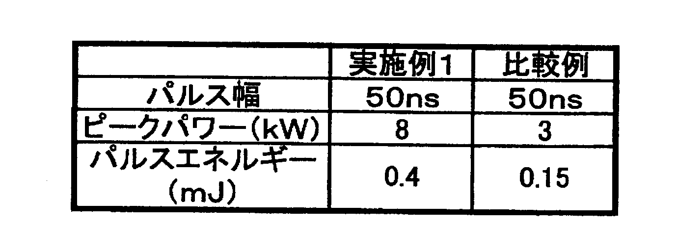
次に、実施例2の光ファイバレーザを作製する際に、ねじれを加えないで作製したPBGFを用いて、実施例2と同様に光ファイバレーザを作製し、これを比較例2の光ファイバレーザとした。実施例2と同様にして、励起光が投入されてから寄生発振が起こるまでの時間を測定した結果、寄生発振が40μs程度で観測された。
これは周期構造中を導波する1040nm付近の光が除去されず、わずかにコアに分布するこの光の成分が、比較例2のPBGFを導波するうちに増幅されたこと、及び導波中に受けた利得が、PBGFから出射された後にアイソレータ等で反射されて再びPBGFに入射するまでの損失に比べて大きかったためである。 <Comparative example 2>
Next, when producing the optical fiber laser of Example 2, an optical fiber laser was produced in the same manner as in Example 2 using PBGF produced without adding twist, and this was used as the optical fiber laser of Comparative Example 2. It was. In the same manner as in Example 2, as a result of measuring the time from when the excitation light was input to when the parasitic oscillation occurred, the parasitic oscillation was observed at about 40 μs.
This is because the light in the vicinity of 1040 nm guided in the periodic structure is not removed, and the component of this light slightly distributed in the core is amplified while being guided through the PBGF of Comparative Example 2, and in the waveguide This is because the gain received in (1) was larger than the loss until it was emitted from the PBGF, reflected by an isolator, etc., and again incident on the PBGF.
PBGFを導波する光は、PBGFから出射するとき、及び入射するときと2回の損失を受ける。そのため、PBGFから光が出射する時、あるいは入射するとき、フォトニックバンドギャップ領域以外の波長の光が受ける損失が、PBGFを導波する際に受ける利得の半分よりも大きければ、寄生発振を抑制できる。そこで、比較例2のPBGFにおいて、入射側及び出射側の接続損失を測定したところ、共に15dB程度であった。したがって、PBGFの入射側及び出射側の接続損失を15dBより大きくすれば、寄生発振が抑制できると、考えられる。 Parasitic oscillation occurs when the return loss on the incident side and the exit side of the PBGF becomes larger than the gain received by the PBGF. That is, parasitic oscillation can be suppressed if the return loss on the incident side and the exit side of the PBGF is larger than the gain received by the PBGF. The reflection attenuation amount on the incident side and the emission side of the PBGF varies depending on the circuit configuration of the optical fiber amplifier, and in some cases, the reflection attenuation amount may be almost zero. On the other hand, when light enters the other optical fiber from the PBGF, the light having a wavelength other than the photonic band gap region receives a large loss because the electric field is almost distributed in the periodic structure.
The light guided through the PBGF undergoes two losses when exiting the PBGF and when entering the PBGF. Therefore, when light is emitted from or incident on the PBGF, if the loss received by light of wavelengths other than the photonic band gap region is greater than half of the gain received when guiding the PBGF, parasitic oscillation is suppressed. it can. Thus, when the connection loss on the incident side and the emission side was measured in the PBGF of Comparative Example 2, both were about 15 dB. Therefore, it is considered that parasitic oscillation can be suppressed by making the connection loss on the incident side and the emission side of PBGF larger than 15 dB.
比較例2のPBGFにおいて、より多くの成分が周期構造中を導波できるように、PBGFの周期構造の層数のみ多くし、入射側及び出射側の接続損失が25dB程度確保できるPBGFを作製した。このPBGFの、コア部の直径は6μm、第1クラッドの直径は125μm、コア吸収量は976nmの波長で1200dB/mである。このPBGFを用いて実施例1と同様に光ファイバレーザを構成し、これを実施例3の光ファイバレーザとした。この光ファイバレーザを、実施例1と同様にして、励起光が投入されてから寄生発振が起こるまでの時間を測定した。
その結果、60μs程度で寄生発振が観測された。 <Example 3>
In the PBGF of Comparative Example 2, only the number of layers of the PBGF periodic structure was increased so that more components could be guided through the periodic structure, and a PBGF that could secure a connection loss of about 25 dB on the incident side and the outgoing side was manufactured. . The PBGF has a core portion diameter of 6 μm, a first cladding diameter of 125 μm, and a core absorption of 1200 dB / m at a wavelength of 976 nm. Using this PBGF, an optical fiber laser was constructed in the same manner as in Example 1, and this was designated as the optical fiber laser of Example 3. In the same manner as in Example 1, this optical fiber laser was measured for the time from when the excitation light was input until the parasitic oscillation occurred.
As a result, parasitic oscillation was observed at about 60 μs.
まず、図6Aに示すPBGFを作製した。コア部は実施例1と同様である。各高屈折率部の間隔は7.3μm、直径は3.7μm、純粋石英ガラスとの比屈折率差は2.8%として作製した。次に、図11に示すように、このPBGFを1mずつ取り出し、直径が100mm、80mmまたは60mmとなるようにそれぞれ1回ずつ巻いた。その後、各PBGFの端面に白色光源を照射してコア部を励起し、透過スペクトルを測定した。この結果を、図12に示す。 <Example 4>
First, PBGF shown in FIG. 6A was produced. The core part is the same as in the first embodiment. The intervals between the high refractive index portions were 7.3 μm, the diameter was 3.7 μm, and the relative refractive index difference from the pure quartz glass was 2.8%. Next, as shown in FIG. 11, this PBGF was taken out 1 m at a time and wound once each so that the diameter became 100 mm, 80 mm or 60 mm. Then, the white light source was irradiated to the end surface of each PBGF, the core part was excited, and the transmission spectrum was measured. The result is shown in FIG.
また、光ファイバを巻く径の大きさが小さくなるほど、得られたグラフが長波長側にシフトしていたことから、光ファイバを巻く際の径を変えることで、容易に希土類イオン添加増幅用光ファイバのゲインプロファイルを制御可能であった。光ファイバの巻く径を変化させても、850nm周辺のイットリウムの励起による自然放出光のフィルタリングには、影響を及ぼさなかった。すなわち、ASE光の除去効果を保ったまま、希土類イオン添加増幅用光ファイバのゲインプロファイルの制御が可能となった。 From FIG. 12, light having a wavelength of about 1100 nm or less was blocked, and light having a wavelength of about 1100 nm or more was transmitted. Therefore, the PBGF used in this example can remove the ASE light having a wavelength of 1000 to 1100 nm guided through the core part by the filter effect by the photonic band gap and can stably oscillate light having a wavelength of about 1100 nm or more. Was confirmed.
Also, the smaller the diameter of the optical fiber wound, the more the obtained graph shifted to the longer wavelength side. Therefore, by changing the diameter when winding the optical fiber, the light for amplification with rare earth ions can be easily obtained. The gain profile of the fiber could be controlled. Changing the winding diameter of the optical fiber did not affect the filtering of spontaneously emitted light by excitation of yttrium around 850 nm. That is, the gain profile of the rare-earth-ion-doped amplification optical fiber can be controlled while maintaining the ASE light removal effect.
Claims (7)
- 種光を発生するレーザ発振器であるマスターオシレータと、このマスターオシレータの後段に接続され、前記マスターオシレータから発せられたレーザ光を増幅して出力する光増幅器であるパワーアンプと、を備えた光ファイバレーザであって、
前記パワーアンプは、
複数の励起光源と、
前記複数の励起光源に各々が接続され、前記励起光源から出射された励起光が入射する励起ポートと、
前記マスターオシレータから発せられたレーザ光が入射される信号ポートと、
前記励起ポートから入射された各前記励起光と、前記信号ポートから入射されたレーザ光とをあわせて出射する出射ポートを有した光結合器と、
前記出射ポートに接続された光ファイバと、
を備え;
前記光ファイバは、フォトニックバンドギャップファイバであり;
前記光ファイバは、横軸が波長、縦軸が損失量を示すグラフにおいて、フォトニックバンドギャップ領域が利得波長帯域よりも狭い損失波長特性を有している;
ことを特徴とする光ファイバレーザ。 An optical fiber comprising: a master oscillator that is a laser oscillator that generates seed light; and a power amplifier that is connected to a subsequent stage of the master oscillator and is an optical amplifier that amplifies and outputs laser light emitted from the master oscillator. A laser,
The power amplifier is
A plurality of excitation light sources;
An excitation port that is connected to each of the plurality of excitation light sources and into which excitation light emitted from the excitation light source is incident;
A signal port to which laser light emitted from the master oscillator is incident;
An optical coupler having an emission port for emitting the excitation light incident from the excitation port and the laser light incident from the signal port;
An optical fiber connected to the exit port;
Comprising:
The optical fiber is a photonic bandgap fiber;
The optical fiber has a loss wavelength characteristic in which a photonic band gap region is narrower than a gain wavelength band in a graph in which a horizontal axis indicates a wavelength and a vertical axis indicates a loss amount;
An optical fiber laser. - 前記光ファイバは、
希土類元素がドープされた固体材料からなるコア部と;
前記コア部の周囲に設けられた第1クラッドと;
前記第1クラッドの前記コア部の近傍に設けられ、前記第1クラッドよりも高い屈折率を持つ多数の高屈折率部が周期構造をなして配置された周期構造部と;
を備えることを特徴とする請求項1に記載の光ファイバレーザ。 The optical fiber is
A core made of a solid material doped with rare earth elements;
A first clad provided around the core portion;
A periodic structure portion provided in the vicinity of the core portion of the first cladding and having a plurality of high refractive index portions having a higher refractive index than that of the first cladding and arranged in a periodic structure;
The optical fiber laser according to claim 1, comprising: - 前記高屈折率部の前記第一クラッドに対する最大比屈折率差が、2%~3%であることを特徴とする請求項1に記載の光ファイバレーザ。 2. The optical fiber laser according to claim 1, wherein the maximum relative refractive index difference of the high refractive index portion with respect to the first cladding is 2% to 3%.
- 前記フォトニックバンドギャップ領域の波長の光の電界分布は、前記コア部の方が前記周期構造部よりも高く;
前記フォトニックバンドギャップ領域以外の波長の光の電界分布は、前記周期構造部の方が前記コア部よりも高い;
ことを特徴とする請求項2に記載の光ファイバレーザ。 An electric field distribution of light having a wavelength in the photonic band gap region is higher in the core portion than in the periodic structure portion;
The electric field distribution of light having a wavelength other than the photonic band gap region is higher in the periodic structure portion than in the core portion;
The optical fiber laser according to claim 2. - 前記高屈折率部には、少なくともゲルマニウムが含まれていることを特徴とする請求項2に記載の光ファイバレーザ。 3. The optical fiber laser according to claim 2, wherein the high refractive index portion contains at least germanium.
- 種光を発生するレーザ発振器であるマスターオシレータと、このマスターオシレータの後段に接続され、前記マスターオシレータから発せられたレーザ光を増幅して出力する光増幅器であるパワーアンプとからなる光ファイバレーザであって、
前記マスターオシレータは、
励起光源と、
この励起光源と接続され、かつ前記励起光源からの励起光とレーザ光とを合波するWDMカプラと、
このWDMカプラと接続された光ファイバと、
この光ファイバに接続された出力カプラと、
アイソレータと、
を備え;
前記WDMカプラと、前記光ファイバと、前記出力カプラと、前記アイソレータとが順にリング状に接続され;
前記光ファイバは、横軸が波長、縦軸が損失量を示すグラフにおいて、フォトニックバンドギャップ領域が利得波長帯域よりも狭い損失波長特性を有している;
ことを特徴とする光ファイバレーザ。 An optical fiber laser comprising a master oscillator that is a laser oscillator that generates seed light and a power amplifier that is connected to a subsequent stage of the master oscillator and amplifies and outputs laser light emitted from the master oscillator. There,
The master oscillator is
An excitation light source;
A WDM coupler that is connected to the excitation light source and combines the excitation light and the laser light from the excitation light source;
An optical fiber connected to the WDM coupler;
An output coupler connected to the optical fiber;
An isolator,
Comprising:
The WDM coupler, the optical fiber, the output coupler, and the isolator are sequentially connected in a ring shape;
The optical fiber has a loss wavelength characteristic in which a photonic band gap region is narrower than a gain wavelength band in a graph in which a horizontal axis indicates a wavelength and a vertical axis indicates a loss amount;
An optical fiber laser. - 種光を発生するレーザ発振器であるマスターオシレータと、このマスターオシレータの後段に接続され、前記マスターオシレータから発せられたレーザ光を増幅して出力する光増幅器であるパワーアンプとからなる光ファイバレーザであって、
前記パワーアンプは、請求項1に記載のパワーアンプであり;
前記マスターオシレータは、請求項6に記載のマスターオシレータである;
ことを特徴とする光ファイバレーザ。 An optical fiber laser comprising a master oscillator that is a laser oscillator that generates seed light and a power amplifier that is connected to a subsequent stage of the master oscillator and amplifies and outputs laser light emitted from the master oscillator. There,
The power amplifier is the power amplifier according to claim 1;
The master oscillator is a master oscillator according to claim 6;
An optical fiber laser.
Priority Applications (5)
| Application Number | Priority Date | Filing Date | Title |
|---|---|---|---|
| JP2009528933A JP4443627B2 (en) | 2008-02-19 | 2009-02-19 | Optical fiber laser |
| EP09712490.3A EP2249443B1 (en) | 2008-02-19 | 2009-02-19 | Optical fiber laser |
| CN2009801057235A CN101946377B (en) | 2008-02-19 | 2009-02-19 | Optical fiber laser |
| US12/859,604 US8270442B2 (en) | 2008-02-19 | 2010-08-19 | Optical fiber laser |
| US13/586,542 US8565273B2 (en) | 2008-02-19 | 2012-08-15 | Optical fiber laser |
Applications Claiming Priority (2)
| Application Number | Priority Date | Filing Date | Title |
|---|---|---|---|
| JP2008038005 | 2008-02-19 | ||
| JP2008-038005 | 2008-02-19 |
Related Child Applications (1)
| Application Number | Title | Priority Date | Filing Date |
|---|---|---|---|
| US12/859,604 Continuation US8270442B2 (en) | 2008-02-19 | 2010-08-19 | Optical fiber laser |
Publications (1)
| Publication Number | Publication Date |
|---|---|
| WO2009104691A1 true WO2009104691A1 (en) | 2009-08-27 |
Family
ID=40985569
Family Applications (1)
| Application Number | Title | Priority Date | Filing Date |
|---|---|---|---|
| PCT/JP2009/052918 WO2009104691A1 (en) | 2008-02-19 | 2009-02-19 | Optical fiber laser |
Country Status (5)
| Country | Link |
|---|---|
| US (2) | US8270442B2 (en) |
| EP (1) | EP2249443B1 (en) |
| JP (1) | JP4443627B2 (en) |
| CN (1) | CN101946377B (en) |
| WO (1) | WO2009104691A1 (en) |
Cited By (5)
| Publication number | Priority date | Publication date | Assignee | Title |
|---|---|---|---|---|
| WO2011007684A1 (en) * | 2009-07-17 | 2011-01-20 | 住友電気工業株式会社 | Photonic crystal fiber |
| JP2011060854A (en) * | 2009-09-07 | 2011-03-24 | Fujikura Ltd | Optical fiber for amplification, and fiber laser device using the same |
| WO2011037749A3 (en) * | 2009-09-23 | 2011-05-19 | Coherent, Inc. | Fibre master oscillator power amplifier (mopa) with amplifying transport fibre |
| JP2011243832A (en) * | 2010-05-20 | 2011-12-01 | Miyachi Technos Corp | Fiber laser processing device |
| JP2014033098A (en) * | 2012-08-03 | 2014-02-20 | Fujikura Ltd | Fiber laser device |
Families Citing this family (13)
| Publication number | Priority date | Publication date | Assignee | Title |
|---|---|---|---|---|
| US20090041063A1 (en) * | 2007-04-10 | 2009-02-12 | Fujikura Ltd. | Fiber laser apparatus |
| US8705912B2 (en) * | 2011-06-03 | 2014-04-22 | Sumitomo Electric Industries, Ltd. | Light source apparatus and processing method |
| CN102513693B (en) * | 2011-11-04 | 2014-08-06 | 杭州奥克光电设备有限公司 | High-power optical fiber laser welding machine |
| TWI473373B (en) * | 2012-11-30 | 2015-02-11 | Ind Tech Res Inst | The apparatus of generating pulse train with tunable spacing time |
| JP5982307B2 (en) * | 2013-03-14 | 2016-08-31 | 株式会社フジクラ | Photonic band gap fiber and fiber laser device using the same |
| FR3007536B1 (en) * | 2013-06-24 | 2015-07-17 | Lyon Ecole Centrale | FIBER OPTIC COMPONENT |
| EP3074801A4 (en) * | 2013-11-26 | 2017-07-05 | IPG Photonics Corporation | Optical fiber with mosaic fiber |
| US9634453B2 (en) * | 2014-12-06 | 2017-04-25 | Alcatel Lucent | Active optical isolators and active optical circulators |
| WO2017044799A1 (en) * | 2015-09-10 | 2017-03-16 | Massachusetts Institute Of Technology | Systems, apparatus, and methods for laser amplification in fiber amplifiers |
| CN105576490A (en) * | 2016-03-09 | 2016-05-11 | 中国科学院合肥物质科学研究院 | Method for realizing laser and frequency-doubled laser by utilizing GaN-based laser-diode-pumped rare-earth-ion-doped laser material |
| JP6830963B2 (en) * | 2016-10-21 | 2021-02-17 | 株式会社フジクラ | Fiber laser device |
| WO2020237148A1 (en) | 2019-05-23 | 2020-11-26 | Lawrence Livermore National Security, Llc | All solid hybrid arrow fiber |
| CN114883898A (en) * | 2022-05-24 | 2022-08-09 | 西安工业大学 | Array distributed high-power all-fiber laser amplifier |
Citations (2)
| Publication number | Priority date | Publication date | Assignee | Title |
|---|---|---|---|---|
| JP2007208107A (en) * | 2006-02-03 | 2007-08-16 | Hitachi Cable Ltd | Optical fiber laser |
| JP2007316526A (en) * | 2006-05-29 | 2007-12-06 | Fujikura Ltd | Photonic band gap fiber and fiber laser |
Family Cites Families (19)
| Publication number | Priority date | Publication date | Assignee | Title |
|---|---|---|---|---|
| JPH03242627A (en) | 1990-02-20 | 1991-10-29 | Nippon Telegr & Teleph Corp <Ntt> | Multistage light amplifier device |
| JP2653936B2 (en) | 1991-05-17 | 1997-09-17 | 沖電気工業株式会社 | Optical amplifier |
| JP2977053B2 (en) | 1991-07-12 | 1999-11-10 | 安藤電気株式会社 | High power optical pulse generator |
| JPH05136498A (en) | 1991-07-22 | 1993-06-01 | Oki Electric Ind Co Ltd | Optical amplifier |
| US5659644A (en) | 1996-06-07 | 1997-08-19 | Lucent Technologies Inc. | Fiber light source with multimode fiber coupler |
| US5864644A (en) | 1997-07-21 | 1999-01-26 | Lucent Technologies Inc. | Tapered fiber bundles for coupling light into and out of cladding-pumped fiber devices |
| US6788865B2 (en) * | 2000-03-03 | 2004-09-07 | Nippon Telegraph And Telephone Corporation | Polarization maintaining optical fiber with improved polarization maintaining property |
| FR2811437A1 (en) * | 2000-07-06 | 2002-01-11 | Cit Alcatel | SHEATH PUMPED OPTICAL FIBER AND METHOD FOR MANUFACTURING SUCH FIBER |
| JP2003035919A (en) | 2000-11-07 | 2003-02-07 | Furukawa Electric Co Ltd:The | Optical amplification apparatus and optical transmission system |
| US6937627B2 (en) * | 2002-01-05 | 2005-08-30 | Jian Lin | Stable and high speed full range laser wavelength tuning with reduced group delay and temperature variation compensation |
| WO2005041367A1 (en) * | 2003-10-24 | 2005-05-06 | Nkt Research & Innovation A/S | An optical system for providing short laser-pulses |
| US20050207455A1 (en) * | 2003-12-15 | 2005-09-22 | Maccormack Stuart | Method and apparatus for efficient coupling of pump light into fiber amplifiers |
| JP2006093613A (en) * | 2004-09-27 | 2006-04-06 | Sumitomo Electric Ind Ltd | Optical fiber, optical fiber amplifier, and optical fiber laser light source |
| JP4561314B2 (en) * | 2004-10-28 | 2010-10-13 | 日立電線株式会社 | Optical fiber for fiber laser, fiber laser, and laser oscillation method |
| US7430352B2 (en) * | 2005-07-29 | 2008-09-30 | Aculight Corporation | Multi-segment photonic-crystal-rod waveguides for amplification of high-power pulsed optical radiation and associated method |
| JP4699131B2 (en) * | 2005-08-05 | 2011-06-08 | 株式会社フジクラ | Optical fiber laser, optical fiber amplifier, MOPA optical fiber laser |
| US7171091B1 (en) * | 2005-08-15 | 2007-01-30 | The United States Of America As Represented By The Secretary Of The Air Force | Tuned cladding fiber amplifier and laser |
| EP1946412A2 (en) * | 2005-10-11 | 2008-07-23 | Clear Align LLC | Apparatus and method for generating short optical pulses |
| JP2007207856A (en) * | 2006-01-31 | 2007-08-16 | Miyachi Technos Corp | Fiber laser processing equipment |
-
2009
- 2009-02-19 EP EP09712490.3A patent/EP2249443B1/en active Active
- 2009-02-19 WO PCT/JP2009/052918 patent/WO2009104691A1/en active Application Filing
- 2009-02-19 CN CN2009801057235A patent/CN101946377B/en not_active Expired - Fee Related
- 2009-02-19 JP JP2009528933A patent/JP4443627B2/en active Active
-
2010
- 2010-08-19 US US12/859,604 patent/US8270442B2/en active Active
-
2012
- 2012-08-15 US US13/586,542 patent/US8565273B2/en active Active
Patent Citations (2)
| Publication number | Priority date | Publication date | Assignee | Title |
|---|---|---|---|---|
| JP2007208107A (en) * | 2006-02-03 | 2007-08-16 | Hitachi Cable Ltd | Optical fiber laser |
| JP2007316526A (en) * | 2006-05-29 | 2007-12-06 | Fujikura Ltd | Photonic band gap fiber and fiber laser |
Cited By (5)
| Publication number | Priority date | Publication date | Assignee | Title |
|---|---|---|---|---|
| WO2011007684A1 (en) * | 2009-07-17 | 2011-01-20 | 住友電気工業株式会社 | Photonic crystal fiber |
| JP2011060854A (en) * | 2009-09-07 | 2011-03-24 | Fujikura Ltd | Optical fiber for amplification, and fiber laser device using the same |
| WO2011037749A3 (en) * | 2009-09-23 | 2011-05-19 | Coherent, Inc. | Fibre master oscillator power amplifier (mopa) with amplifying transport fibre |
| JP2011243832A (en) * | 2010-05-20 | 2011-12-01 | Miyachi Technos Corp | Fiber laser processing device |
| JP2014033098A (en) * | 2012-08-03 | 2014-02-20 | Fujikura Ltd | Fiber laser device |
Also Published As
| Publication number | Publication date |
|---|---|
| EP2249443A1 (en) | 2010-11-10 |
| EP2249443A4 (en) | 2013-09-04 |
| US20100329288A1 (en) | 2010-12-30 |
| US8565273B2 (en) | 2013-10-22 |
| CN101946377B (en) | 2012-11-07 |
| CN101946377A (en) | 2011-01-12 |
| JP4443627B2 (en) | 2010-03-31 |
| EP2249443B1 (en) | 2020-07-08 |
| US20120307848A1 (en) | 2012-12-06 |
| US8270442B2 (en) | 2012-09-18 |
| JPWO2009104691A1 (en) | 2011-06-23 |
Similar Documents
| Publication | Publication Date | Title |
|---|---|---|
| JP4443627B2 (en) | Optical fiber laser | |
| JP5238509B2 (en) | Photonic bandgap fiber | |
| JP5185929B2 (en) | Fiber laser | |
| CA2693854C (en) | Light emitting devices with phosphosilicate glass | |
| JP4243327B2 (en) | Photonic band gap fiber and fiber amplifier | |
| US8498044B2 (en) | Amplification optical fiber, and optical fiber amplifier and resonator using the same | |
| JP2009032910A (en) | Optical fiber for optical fiber laser, method of manufacturing the same and optical fiber laser | |
| JP2010129886A (en) | Optical fiber for fiber laser, and fiber laser | |
| EP3005496B1 (en) | Multimode fabry-perot fiber laser | |
| US11835776B2 (en) | Filter device and laser apparatus | |
| WO2021045074A1 (en) | Optical amplifying device | |
| WO2020203930A1 (en) | Active element added-optical fiber, resonator, and fiber laser device | |
| JP5014640B2 (en) | Multimode fiber, optical amplifier and fiber laser | |
| US20090041063A1 (en) | Fiber laser apparatus | |
| Kurkov et al. | High-power Yb-doped double-clad fiber lasers for a range of 0.98-1.04 µm. | |
| JP7177090B2 (en) | High-power cladding-pumped single-mode fiber Raman laser | |
| WO2007077419A1 (en) | Optical fibre with angled core | |
| JP2009047771A (en) | Optical fiber raman laser apparatus | |
| US20220123517A1 (en) | Optical fiber devices and methods for reducing stimulated raman scattering (srs) light intensity in signal combined systems | |
| JP2001358388A (en) | Optical fiber, optical fiber amplifier, and fiber laser | |
| JP2020077765A (en) | Optical fiber laser device | |
| JP2010177314A (en) | Double clad fiber, fiber laser device, and optical amplifier |
Legal Events
| Date | Code | Title | Description |
|---|---|---|---|
| WWE | Wipo information: entry into national phase |
Ref document number: 200980105723.5 Country of ref document: CN |
|
| ENP | Entry into the national phase |
Ref document number: 2009528933 Country of ref document: JP Kind code of ref document: A |
|
| 121 | Ep: the epo has been informed by wipo that ep was designated in this application |
Ref document number: 09712490 Country of ref document: EP Kind code of ref document: A1 |
|
| NENP | Non-entry into the national phase |
Ref country code: DE |
|
| WWE | Wipo information: entry into national phase |
Ref document number: 2009712490 Country of ref document: EP |