WO2009104361A1 - Polymer heating element - Google Patents
Polymer heating element Download PDFInfo
- Publication number
- WO2009104361A1 WO2009104361A1 PCT/JP2009/000434 JP2009000434W WO2009104361A1 WO 2009104361 A1 WO2009104361 A1 WO 2009104361A1 JP 2009000434 W JP2009000434 W JP 2009000434W WO 2009104361 A1 WO2009104361 A1 WO 2009104361A1
- Authority
- WO
- WIPO (PCT)
- Prior art keywords
- heating element
- polymer
- conductive layer
- resistor
- element according
- Prior art date
Links
Images


Classifications
-
- H—ELECTRICITY
- H05—ELECTRIC TECHNIQUES NOT OTHERWISE PROVIDED FOR
- H05B—ELECTRIC HEATING; ELECTRIC LIGHT SOURCES NOT OTHERWISE PROVIDED FOR; CIRCUIT ARRANGEMENTS FOR ELECTRIC LIGHT SOURCES, IN GENERAL
- H05B3/00—Ohmic-resistance heating
- H05B3/20—Heating elements having extended surface area substantially in a two-dimensional plane, e.g. plate-heater
- H05B3/34—Heating elements having extended surface area substantially in a two-dimensional plane, e.g. plate-heater flexible, e.g. heating nets or webs
-
- A—HUMAN NECESSITIES
- A47—FURNITURE; DOMESTIC ARTICLES OR APPLIANCES; COFFEE MILLS; SPICE MILLS; SUCTION CLEANERS IN GENERAL
- A47C—CHAIRS; SOFAS; BEDS
- A47C7/00—Parts, details, or accessories of chairs or stools
- A47C7/62—Accessories for chairs
- A47C7/72—Adaptations for incorporating lamps, radio sets, bars, telephones, ventilation, heating or cooling arrangements or the like
- A47C7/74—Adaptations for incorporating lamps, radio sets, bars, telephones, ventilation, heating or cooling arrangements or the like for ventilation, heating or cooling
- A47C7/748—Adaptations for incorporating lamps, radio sets, bars, telephones, ventilation, heating or cooling arrangements or the like for ventilation, heating or cooling for heating
-
- B—PERFORMING OPERATIONS; TRANSPORTING
- B60—VEHICLES IN GENERAL
- B60N—SEATS SPECIALLY ADAPTED FOR VEHICLES; VEHICLE PASSENGER ACCOMMODATION NOT OTHERWISE PROVIDED FOR
- B60N2/00—Seats specially adapted for vehicles; Arrangement or mounting of seats in vehicles
- B60N2/56—Heating or ventilating devices
- B60N2/5678—Heating or ventilating devices characterised by electrical systems
- B60N2/5685—Resistance
-
- H—ELECTRICITY
- H05—ELECTRIC TECHNIQUES NOT OTHERWISE PROVIDED FOR
- H05B—ELECTRIC HEATING; ELECTRIC LIGHT SOURCES NOT OTHERWISE PROVIDED FOR; CIRCUIT ARRANGEMENTS FOR ELECTRIC LIGHT SOURCES, IN GENERAL
- H05B2203/00—Aspects relating to Ohmic resistive heating covered by group H05B3/00
- H05B2203/011—Heaters using laterally extending conductive material as connecting means
-
- H—ELECTRICITY
- H05—ELECTRIC TECHNIQUES NOT OTHERWISE PROVIDED FOR
- H05B—ELECTRIC HEATING; ELECTRIC LIGHT SOURCES NOT OTHERWISE PROVIDED FOR; CIRCUIT ARRANGEMENTS FOR ELECTRIC LIGHT SOURCES, IN GENERAL
- H05B2203/00—Aspects relating to Ohmic resistive heating covered by group H05B3/00
- H05B2203/017—Manufacturing methods or apparatus for heaters
-
- H—ELECTRICITY
- H05—ELECTRIC TECHNIQUES NOT OTHERWISE PROVIDED FOR
- H05B—ELECTRIC HEATING; ELECTRIC LIGHT SOURCES NOT OTHERWISE PROVIDED FOR; CIRCUIT ARRANGEMENTS FOR ELECTRIC LIGHT SOURCES, IN GENERAL
- H05B2203/00—Aspects relating to Ohmic resistive heating covered by group H05B3/00
- H05B2203/029—Heaters specially adapted for seat warmers
-
- H—ELECTRICITY
- H05—ELECTRIC TECHNIQUES NOT OTHERWISE PROVIDED FOR
- H05B—ELECTRIC HEATING; ELECTRIC LIGHT SOURCES NOT OTHERWISE PROVIDED FOR; CIRCUIT ARRANGEMENTS FOR ELECTRIC LIGHT SOURCES, IN GENERAL
- H05B2214/00—Aspects relating to resistive heating, induction heating and heating using microwaves, covered by groups H05B3/00, H05B6/00
- H05B2214/04—Heating means manufactured by using nanotechnology
Definitions
- the present invention relates to a polymer heating element using Joule heat of a polymer resistor, and more particularly to a polymer heating element that has long-term reliability and can be produced at low cost.
- a material obtained by dispersing a conductive material such as carbon black, metal powder, or graphite in a resin is known.
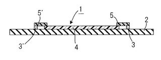
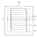
- FIGS. 7 is a plan view of the heating element
- FIG. 8 is an XY cross-sectional view of FIG.
- Examples of conventional polymer resistors formed by printing and used as heating elements include automobile door mirrors, washstand mirrors, floor heating appliances, etc., for dew / frost removal (for example, patent documents) 1). JP 2002-371699 A
- the specific resistance of the resistor composition used is usually 1000 ⁇ ⁇ cm or more, so that power is supplied in close proximity like a comb-shaped electrode.
- the comb-shaped electrode is made of silver paste, and is formed by printing and drying. Therefore, the amount of the comb-shaped electrode increases, so that the comb electrode is expensive.
- a heat generating part can be formed in a thin film of about several tens of micrometers by adjusting the coating amount, and therefore it is easy to exhibit flexibility as a polymer heating element.
- a smooth, non-impregnated, and electrically insulating base material such as a polyester film with a waist as the surface on which the ink-like polymer resistor is applied, resulting in a loss of flexibility. It was. Further, since it is necessary to use a large amount of expensive conductive paste as a comb-shaped electrode as a power feeding portion of the polymer heating element, there is a disadvantage that the cost is high.
- the resistor used for extrusion molding is thicker in millimeters than the one used for ink, lacks flexibility, and has a configuration in which the electrode cables are close to each other, so that it cannot be said to be a planar heating element.
- thin-wall molding methods such as T-die extrusion and calendering, but no polymer resistor suitable for these methods has been proposed.
- the problem to be solved by the present invention is to improve the usability and reliability of a planar heating element when a polymer resistor exhibiting low resistance capable of thin molding is provided. Another object is to provide a polymer heating element that is reduced in cost.
- the polymer heating element of the present invention includes an electrically insulating substrate and at least a pair of electrodes composed of a plurality of fine metal wires disposed on the electrically insulating substrate, A polymer resistor having a PTC characteristic that is not in direct contact with the pair of electrodes, and a conductive layer in contact with both the electrode and the polymer resistor, wherein the conductive layer includes at least a crosslinkable resin component; And a conductor component.
- the polymer heating element of the present invention includes, as a third aspect, an electrically insulating substrate, a polymer resistor having a PTC characteristic disposed on the electrically insulating substrate, and the polymer resistor.
- a polymer heating element formed of at least a pair of electrodes composed of a plurality of fine metal wires not in direct contact with a body and a conductive layer in contact with both the polymer resistor and the electrode, The layer exhibits PTC characteristics.
- a polymer resistor showing low resistance is basically formed in a thin film. This configuration eliminates the need for a comb-shaped configuration between the electrodes that supply power to the polymer resistor, making it possible to arrange the electrodes at wide intervals, reducing the amount of electrodes used, and patterning the polymer resistor Therefore, it is possible to provide a low-cost planar heating element.
- the first point is an improvement in bending resistance by providing a coating on the electrode itself.
- the coating resin exhibits a buffer-like effect and the bending resistance is improved as compared with the case where only the electrode is bent.
- the second point is improvement in adhesion between the electrode part and the polymer resistor part via the conductive layer.
- cracks may occur in the polymer resistor, depending on the conditions during the pressure bonding.
- the resin component of the conductive layer exists when the conductive layer is interposed, for example, an electrode coated with a conductive layer in advance is extruded and the coated conductive electrode is melted into a polymer resistor. When worn, it was found that good adhesion and adhesion could be obtained without cracks.
- the third point is that the composition of the conductive layer is different from that of the polymer resistor even if a part of the electrode portion made of a metal wire is disconnected or close to the disconnection and current concentration occurs.
- a component for example, an inflammable material such as an inorganic conductive material or a metal material, it is possible to exhibit a barrier effect that does not lead to smoke and ignition.
- the second aspect of the present invention pays particular attention to the second role.
- the composition containing a crosslinkable resin component as the resin component of the conductive layer satisfies the above conditions. And found the present invention.
- the resin has excellent structural stability and thermal stability compared to a non-cross-linked resin, and it is possible to maintain low resistance characteristics, which is one of the roles as a conductive layer, over a long period of time. is there.
- the thermal change and structure of the conductive layer and the polymer resistor are selected.
- the inventors have found that the change is close, and that a structure in which cracks or the like are not generated at the interface portion can be obtained over a long period of time, and the present invention has been achieved. That is, also in the material composition of the conductive layer, the object of the present invention can be achieved by making the material composition exhibiting the PTC characteristic like the polymer resistor.
- the electrode and the conductive layer, and the conductive layer and the polymer resistor are in a state of being bonded and in close contact with each other.
- the state of coating of the electrode itself does not matter.
- the electrode portion may be entirely covered with the conductive layer, or may be in a state where only a part is covered.
- the present invention it is possible to provide a sheet heating element having a thin film and a low resistance, to improve usability and reliability, and to promote cost reduction.
- FIG. 3 is a plan view showing the configuration of the polymer heating element according to Embodiments 1 to 6 of the present invention.
- XY sectional view of FIG. FIG. 6 is a perspective side view showing a seat device for an automobile to which a polymer heating element according to Embodiments 1 to 8 of the present invention is attached.
- A Plan view of polymer heating element in Embodiment 7 of the present invention, (b) Cross-sectional view of the polymer heating element, (c) Enlarged view of the polymer heating element
- A A plan view of a polymer heating element in Embodiment 8 of the present invention, (b) a sectional view of the polymer heating element, and (c) an enlarged view of the polymer heating element.
- the first invention is an electrical insulating base material, at least a pair of electrodes composed of a plurality of fine metal wires disposed on the electrical insulating base material, and the PTC that is not in direct contact with the pair of electrodes.
- a polymer resistor having characteristics, and a conductive layer in contact with both the electrode and the polymer resistor, wherein the conductive layer includes at least a resin component, a conductor component, and an additive component.
- the conductive layer provided between the electrode composed of a plurality of fine metal wires and the polymer resistor plays a role of mediating the adhesion between the electrode and the polymer resistor, and the metal wires are directly connected to the polymer resistor. Compared to the case of bonding, durability such as flexibility can be improved.
- the resin component of the conductive layer has a functional group exhibiting metal affinity, and at the interface between the conductive layer and the metal serving as the electrode. Since the contact state can be kept good, a heating element with good heat generation characteristics can be easily obtained.
- a PTC characteristic in which an electrically insulating base material, at least a pair of electrodes composed of a plurality of fine metal wires arranged on the electrically insulating base material, and the pair of electrodes are not in direct contact with each other
- the conductive layer including at least a crosslinkable resin component and a conductive component, and a conductive layer Since the resin component is composed of a crosslinkable resin component, it is possible to obtain a conductive layer having excellent thermal stability and little change in the long term.
- the conductive layer provided between the electrode composed of a plurality of thin metal wires and the polymer resistor plays a role of mediating the adhesion between the electrode and the polymer resistor, and the metal wires are directly connected to the polymer resistor. Compared with the case where it bonds together, durability performance, such as a flexibility, can be improved.
- the conductive layer contains a crosslinkable resin component, a conductive component, and a melt tension improving agent component, so that the resin component and the conductive component
- the dispersibility of the conductor component and the like can be improved during the kneading dispersion processing, and the tension of the molten resin can be improved, and the desired component can be added without reducing the moldability of the resin in balance with the reactive crosslinking agent. It becomes possible to obtain the resin composition which has it easily.
- the fifth invention is a polymer heating element of the third or fourth invention, in which the crosslinkable resin component of the conductive layer is crosslinked with a reactive additive, and the resin component and the conductor component are combined. Since the crosslinking reaction can proceed while kneading and dispersing, the conductive layer composition can be prepared by a simple method in terms of construction.
- the weight ratio of the conductive component of the conductive layer is 50 wt% to 80 wt% with respect to the weight of the conductive layer. is there.
- the conductor is included in the conductive layer at this weight ratio, even when the electrode made of a thin metal wire is disconnected, the presence of a larger amount of the conductor component than the resin component causes disconnection and current concentration. , Can suppress the occurrence of sparks. Moreover, since it will contain 20 weight% or more of a resin component and an additive component by setting it as 80 weight% or less, the flexibility as a conductive layer and a certain amount of softness
- the conductive component of the conductive layer is carbon black, graphite, carbon nanotube, carbon fiber, conductive ceramic. It contains a conductor selected from at least one of fiber, conductive whisker, metal fiber, conductive inorganic oxide, and conductive polymer fiber, and since the raw material of the conductor can be obtained relatively inexpensively and stably, A high-quality polymer heating element with reduced cost can be provided.
- the additive component of the conductive layer contains at least one flame retardant of a phosphorus type, a nitrogen type, and a silicone type, thereby heating from the outside.
- a polymer heating element that can suppress smoke and ignition can be provided.
- the specific resistance of the conductive layer is set to 0.01 to 500 ⁇ ⁇ cm. It is possible to create a polymer heating element that is electrically stable.
- an electrically insulating substrate a polymer resistor having a PTC characteristic disposed on the electrically insulating substrate, and a plurality of fine metal wires that are not in direct contact with the polymer resistor.
- the conductive layer exhibits PTC characteristics and is thermally stable. It is possible to obtain a conductive layer that is excellent in properties and has little change over the long term.
- the conductive layer provided between the electrode composed of a plurality of thin metal wires and the polymer resistor plays a role of mediating the adhesion between the electrode and the polymer resistor, and the metal wires are directly connected to the polymer resistor. Compared with the case where it bonds together, durability performance, such as a flexibility, can be improved.
- the distance between the polymer resistor and the electrode is in the range of 0.01 mm to 3 mm, and the conductive layer existing between them is a metal electrode.
- the polymer resistor can play a role as a buffer material, and can smoothly generate heat without causing a large resistance when a voltage is applied.
- the interval is narrower than 0.01 mm, although depending on the variation of the construction method, the metal serving as the electrode and the polymer resistor are in direct contact with each other, and the barrier effect against the smoke and ignition of the third role described above. It is difficult to make full use of.
- it exceeds 3 mm although it depends on the specific resistance of the conductive layer, the heat loss in the conductive layer increases, which is not preferable as a characteristic of a polymer resistor.
- the conductive layer has PTC characteristics, and the resistance value at 80 ° C. is 10 times or less than the resistance value at 20 ° C.
- a similar material composition having the same PTC characteristic as that of the polymer resistor can be used to improve the mutual adhesion and the like.
- the PTC characteristic of the conductive layer itself is a PTC in a high temperature state.
- the heat generation temperature is generally at a relatively high temperature level, but the resistance value change magnification as the PTC characteristic is 20 even in the heat generation state near 80 ° C. More preferably, it is 10 times or less with respect to ° C.
- the ratio of the specific resistance of the high molecular resistance to the specific resistance of the conductive layer is 100 times in the temperature range of 80 ° C. or less. It becomes the following. Even when the specific resistance values of the polymer resistor and the conductive layer are equal, the coating layer has a narrow interval, so the resistance value is considered to be about 1/1000. A good heating element can be obtained without the resistance of the conductive layer inhibiting the heat generation of the polymer resistor.
- a fourteenth invention is characterized in that, in the polymer heating element of any one of the tenth to thirteenth inventions, the conductive layer is parallel to the electrode, and the voltage application direction is Since the conductive layer exists with a uniform thickness and width, almost the same voltage is applied to the polymer heating element in any region, and a heating element with good uniform heating can be obtained. It becomes.
- the fifteenth aspect of the invention is a polymer heating element of any one of the tenth to fourteenth aspects of the present invention, which is obtained by co-extrusion molding of the composition of the conductive layer and the fine metal wire constituting the electrode.
- the adhesion between the electrode and the conductive layer can be improved. Since the electrode having the conductive layer thus prepared can be molded as a heating element by heat fusion with a polymer resistor, the heating element can be obtained by a relatively simple method.
- the electrode in the polymer heating element of any one of the first, third, and tenth aspects of the invention, may be a fine metal wire including at least one of tin-plated copper, silver-containing copper, and silver-copper alloy. Therefore, the polymer heating element having good heat generation characteristics can be provided for a long period of time because of excellent flexibility and flexibility.
- the electrically insulating base material comprises at least one of a resin film, a woven fabric, and a non-woven fabric.
- a polymer heating element excellent in long-term reliability can be obtained.
- the polymer heating elements described in the first to seventeenth aspects are arranged, for example, on at least one of a seat portion and a backrest portion, and are mounted on an automobile seat device as a heating heat source.
- the polymer heating element 1 includes a pair of electrodes 3 and 3 ′, a polymer resistor 4, and conductive layers 5 and 5 ′ on an electrically insulating substrate 2.
- the electrically insulating substrate 2 is a needle punch type made of polyester fiber, and a nonwoven fabric impregnated with a flame retardant can be used.
- the pair of electrodes 3 and 3 ′ were obtained by twisting 15 silver-copper alloy wires having a wire diameter of 0.06 mm, and were obtained by heat-sealing treatment at predetermined positions on the nonwoven fabric.
- the polymer resistor 4 is disposed by thermal fusion so as not to directly contact the electrodes 3 and 3 ′, and then the conductive layer 5 for contacting the polymer resistor 4 and the electrodes 3 and 3 ′. , 5 'are formed by heat fusion.
- a lead wire for supplying power to the electrodes 3 and 3 ' is omitted.
- the polymer resistor 4 was prepared by preparing a kneaded material according to the following materials and procedures and then processing it into a film by calendering.
- the polymer resistor 4 includes, as a crystalline resin, 30 parts of an ethylene / methacrylic acid copolymer (trade name “Aklift CM5021”, melting point 67 ° C., manufactured by Sumitomo Chemical Co., Ltd.) and ethylene / methacrylic. 30 parts of an acid copolymer (trade name “Nucleel N1560”, melting point 90 ° C., manufactured by Mitsui DuPont Polychemical Co., Ltd.), an ethylene / methacrylic acid copolymer metal coordination product (trade name “Himiran 1702”, Melting point 90 ° C., 40 parts by Mitsui DuPont Polychemica Co., Ltd.
- an acid copolymer trade name “Nucleel N1560”, melting point 90 ° C., manufactured by Mitsui DuPont Polychemical Co., Ltd.
- an ethylene / methacrylic acid copolymer metal coordination product trade name “Himiran 1702”, Melting point 90 °
- styrene thermoplastic elastomer (trade name “Tuftec M1943”), 40% by weight, manufactured by Asahi Kasei Engineering Co., Ltd., carbon black (trade name “# 10B”, primary particle diameter 75 nm, Mitsubishi Chemical) 45% by weight manufactured by Co., Ltd., 13% by weight tungsten carbide (manufactured by Izawa Metal Co., Ltd.), and an alkyl methacrylate / alkyl acrylate copolymer and tetrafluoroethylene copolymer as melt tension improvers.
- a kneaded product B was prepared from 2% by weight of the mixture (trade name “METABREN A3000”, manufactured by Mitsubishi Rayon Co., Ltd.).
- the conductive layers 5 and 5 ′ have 21 wt% of ethylene vinyl acetate copolymer (trade name “Evaflex EV150”, manufactured by Mitsui DuPont Polychemical Co., Ltd.) as a resin component and a functional group exhibiting metal affinity.
- ethylene vinyl acetate copolymer trade name “Evaflex EV150”, manufactured by Mitsui DuPont Polychemical Co., Ltd.
- Conductive whisker (product) with 9% by weight of a resin containing maleic anhydride (trade name “Bondaine LX4110”, ethylene-acrylic acid ester-maleic anhydride terpolymer resin, manufactured by Sumitomo Chemical Co., Ltd.) Name “FTL-110”, acicular titanium oxide, manufactured by Ishihara Sangyo Co., Ltd.) 45% by weight, carbon black (trade name “Printex L”, primary particle size 21 nm, manufactured by Degussa) 15% by weight, flame retardant (Product name “Reophos RDP”, phosphate ester liquid flame retardant, manufactured by Ajinomoto Co., Inc.) 10% by weight to obtain a kneaded product, and a film having a thickness of 100 ⁇ m was obtained. The specific resistance was 5 ⁇ ⁇ cm.
- the polymer heating element 1 constituting the planar heating element is attached, for example, to a seat portion 7 and a backrest 8, which are a seat device 6 of an automobile, with the base material 2 side as an upper portion. It is what is used.
- an ear portion (an extended portion of the base material 2) is provided to be suspended at the central portion or the peripheral portion, but is omitted here. Yes.
- the seat 7 and the backrest 8 to which the polymer heating element 1 is mounted are generally deformed when a load is applied by a human body seated on the seat, such as a urethane pad that is restored when the load is no longer applied.
- a seat base 9 and a seat skin 10 are provided.
- the polymer heating element 1 which is a thin sheet heating element mounted on the seat base 7 and the seat base 9 of the backrest 8 with the polymer resistor 4 side disposed on the seat skin 10 and the base material 2 side is also mounted.
- a similar deformation must be made corresponding to the deformation of the seat 7 and the backrest 8 described above.
- the electrodes 3 and 3 ′ are arranged in such a manner that a wide pair (electrically positive side and negative side) is arranged along the outer side in the longitudinal direction of the polymer heating element 1 so as to face each other and come into contact therewith.
- a current flows through the polymer resistor 4 through the disposed conductive layers 5 and 5 ', and heat is generated.
- the polymer resistor 4 has PTC characteristics, and when the temperature rises, the resistance value rises, and has a self-temperature adjusting function so as to reach a predetermined temperature, and temperature control is unnecessary. It has a function as a highly safe planar heating element.
- the seating feeling can be satisfied by the fact that there is no squeaking like paper and has the same elongation characteristics as the seat skin material, that is, a load of 7 kgf or less for 5% elongation.
- planar heating element having PTC characteristics, quick heat and energy saving can be exhibited as compared with a conventional heating element using a tubing heater.
- the tube heater that uses a heating element requires a temperature controller and controls the heat generation temperature by controlling energization with ON-OFF control.
- the heater wire temperature when ON is increased to about 80 ° C., it is necessary to arrange the heater wire at a certain distance from the seat skin material.
- the heating temperature is high. Since it is self-controlled within the range of 40 ° C. to 50 ° C., it can be placed close to the seat skin material. Since the heat generation temperature is low and it is in the vicinity of the seat, it is possible to realize energy saving by being able to reduce heat loss and heat dissipation loss to the outside.
- flame retardancy can be realized by using a flame retardant nonwoven fabric for the electrically insulating base material 2 and blending a flame retardant with the polymer resistor 4 and the conductive layers 5 and 5 ′.
- Flame retardancy is the automotive interior material flame retardant standard FMVSS302 (single fire extinguishing as well as non-flammability with horizontal ignition, or if the burning speed between marked lines is 80 mm / min or less It has been confirmed that it can be satisfied if the amount of the flame retardant is at least 10% by weight.
- the polymer heating element obtained in this embodiment was subjected to a standing test in an 80 ° C. furnace, a standing test in a 150 ° C. furnace, and a heat cycle test at ⁇ 20 ° C. and 50 ° C.
- the resistance value change rate was within 30% of the initial value after 500 hours, 200 hours, and 200 times, respectively.
- the reason for this was considered to be that the crystalline resin itself and the bonding between the crystalline resin and the conductor were attempted by a crosslinking reaction with the reactive resin.
- the conductor is required to achieve a predetermined resistance value with the smallest possible addition amount, but such a conductor is generally called conductive carbon black, and has a primary particle diameter of about 20 nm or less and a structure. (It is an aggregate of primary particles such as a bunch of coral, which is correlated with oil absorption.) On the other hand, such conductive carbon black exhibits PTC characteristics. It had the disadvantage of being difficult to do.
- a conductor such as graphite has a larger particle diameter than carbon black and has a layered structure such as a scale, and a conductor such as a metal or ceramic has a large particle diameter and is amorphous.
- the inventors have obtained as knowledge that they have excellent electrical conductivity (small volume resistivity (one hundredth or less of carbon or graphite)).
- the thickness is about 100 microns or less
- the sheet resistance is 400 ⁇ / ⁇ or less
- the specific resistance is 3 ⁇ ⁇ cm or less
- a resistance composition in which the ratio of the resistance value at 50 ° C. to the resistance value at 20 ° C. is 1.5 or more and the ratio of the resistance value at 80 ° C. to the resistance value at 20 ° C. is 5 or more in the resistance value change ratio with respect to temperature. I was able to.
- waxes such as montanic acid partly saponified esters, and plasticizers and dispersants such as other waxes may be used as necessary.
- the conductor is formed using a whisker shape, it may be spherical or other rug shape.
- the polymer resistor 4 and the electrodes 3 and 3 ′ are shown so as not to overlap each other in the same plane. It may be arranged.
- the electrically insulating base material 2 is a fine embossed material made of polyester fiber, and a nonwoven fabric impregnated with a flame retardant can be used.
- the pair of electrodes 3 and 3 ′ were obtained by twisting 19 tin-plated copper wires having a wire diameter of 0.08 mm, and were heat-bonded at predetermined positions on the nonwoven fabric.
- the polymer resistor 4 is disposed by thermal fusion so as not to directly contact the electrodes 3 and 3 ′, and then the conductive layers 5 and 5 for contacting the electrodes 3 and 3 ′ and the polymer resistor 4.
- the polymer heating element 1 was obtained by thermally fusing '.
- a lead wire for supplying power to the electrodes 3 and 3 ' is omitted.
- the polymer resistor 4 was processed by the same method as in the first embodiment.
- the conductive layers 5 and 5 ′ have, as a resin component, 21% by weight of an ethylene vinyl acetate copolymer (trade name “Evaflex EV150”, manufactured by Mitsui DuPont Polychemical Co., Ltd.) and a functional group exhibiting metal affinity.
- a conductive whisker (trade name “FTL-110”, needle-shaped) containing 9% by weight of a resin (trade name “Tuftec M1943” (modified type of hydrogenated styrene thermoplastic elastomer, manufactured by Asahi Kasei Co., Ltd.)) Titanium oxide, manufactured by Ishihara Sangyo Co., Ltd.
- the polymer resistor 4 has PTC characteristics, and when the temperature rises, the resistance value rises, and has a self-temperature adjusting function so as to reach a predetermined temperature, and temperature control is unnecessary. It has a function as a highly safe planar heating element.
- a car seat heater of a planar heating element incorporated in an automobile seat device it can satisfy a seating feeling and flame retardancy.
- the seating feeling can be satisfied by the fact that there is no squeaking like paper and has the same elongation characteristics as the seat skin material, that is, a load of 7 kgf or less for 5% elongation.
- planar heating element having PTC characteristics, quick heat and energy saving can be exhibited as compared with a conventional heating element using a tubing heater.
- the tube heater that uses a heating element requires a temperature controller and controls the heat generation temperature by controlling energization with ON-OFF control.
- the heater wire temperature when ON is increased to about 80 ° C., it is necessary to arrange the heater wire at a certain distance from the seat skin material.
- the heating temperature is high. Since it is self-controlled within the range of 40 ° C. to 50 ° C., it can be placed close to the seat skin material. Since the heat generation temperature is low and it is in the vicinity of the seat, it is possible to realize energy saving by being able to reduce heat loss and heat dissipation loss to the outside.
- flame retardancy can be realized by using a flame retardant nonwoven fabric for the electrically insulating base material 2 and blending a flame retardant with the polymer resistor 4 and the conductive layers 5 and 5 ′.
- Flame retardancy is the automotive interior material flame retardant standard FMVSS302 (single fire extinguishing as well as non-flammability with horizontal ignition, or if the burning speed between marked lines is 80 mm / min or less It has been confirmed that it can be satisfied if the amount of the flame retardant is at least 10% by weight.
- the polymer heating element obtained in this embodiment was subjected to a standing test in an 80 ° C. furnace, a standing test in a 150 ° C. furnace, and a heat cycle test at ⁇ 20 ° C. and 50 ° C.
- the resistance value change rate was within 30% of the initial value after 500 hours, 200 hours, and 200 times, respectively.
- the polymer resistor 4 and the electrodes 3 and 3 ′ are shown so as not to overlap each other in the same plane.
- the polymer resistor 4 and the electrodes 3 and 3 ′ are stacked as long as they are in contact with each other through the conductive layers 5 and 5 ′.
- the arrangement may be different.
- the electrically insulating base material 2 is a fine embossed material made of polyester fiber, and a nonwoven fabric impregnated with a flame retardant can be used.
- the pair of electrodes 3 and 3 ′ is obtained by arranging 19 silver-copper alloy wires containing 3% silver having a wire diameter of 0.06 mm in parallel, and can be heat-sealed at a predetermined position on the nonwoven fabric. It was.
- the polymer resistor 4 is disposed by thermal fusion so as not to directly contact the electrodes 3 and 3 ′, and then the conductive layers 5 and 5 for contacting the electrodes 3 and 3 ′ and the polymer resistor 4.
- the polymer heating element 1 was obtained by thermally fusing '.
- a lead wire for supplying power to the electrodes 3 and 3 ' is omitted.
- the polymer resistor 4 was processed by the same method as in the first embodiment.
- the conductive layers 5 and 5 ' are the same as those in the first embodiment.
- the polymer resistor 4 has PTC characteristics, and when the temperature rises, the resistance value rises, and has a self-temperature adjusting function so as to reach a predetermined temperature, and temperature control is unnecessary. It has a function as a highly safe planar heating element.
- a car seat heater of a planar heating element incorporated in an automobile seat device it can satisfy a seating feeling and flame retardancy.
- the seating feeling can be satisfied by the fact that there is no squeaking like paper and has the same elongation characteristics as the seat skin material, that is, a load of 7 kgf or less for 5% elongation.
- planar heating element having PTC characteristics, quick heat and energy saving can be exhibited as compared with a conventional heating element using a tubing heater.
- the tube heater that uses a heating element requires a temperature controller and controls the heat generation temperature by controlling energization with ON-OFF control.
- the heater wire temperature when ON is increased to about 80 ° C., it is necessary to arrange the heater wire at a certain distance from the seat skin material.
- the heating temperature is high. Since it is self-controlled within the range of 40 ° C. to 50 ° C., it can be placed close to the seat skin material. Since the heat generation temperature is low and it is in the vicinity of the seat, it is possible to realize energy saving by being able to reduce heat loss and heat dissipation loss to the outside.
- flame retardancy can be realized by using a flame retardant nonwoven fabric for the electrically insulating base material 2 and blending a flame retardant with the polymer resistor 4 and the conductive layers 5 and 5 ′.
- Flame retardancy is the automotive interior material flame retardant standard FMVSS302 (single fire extinguishing as well as non-flammability due to horizontal ignition, or if the burning speed between marked lines is 80 mm / min or less It has been confirmed that it can be satisfied if the amount of the flame retardant is at least 10% by weight.
- the polymer heating element obtained in this embodiment was subjected to a standing test in an 80 ° C. furnace, a standing test in a 150 ° C. furnace, and a heat cycle test at ⁇ 20 ° C. and 50 ° C.
- the resistance value change rate was within 30% of the initial value after 500 hours, 200 hours, and 200 times, respectively.
- the polymer resistor 4 and the electrodes 3 and 3 ′ are shown so as not to overlap each other in the same plane.
- the polymer resistor 4 and the electrodes 3 and 3 ′ are stacked as long as they are in contact with each other through the conductive layers 5 and 5 ′.
- the arrangement may be different.
- a kneaded material was prepared according to the following materials and procedures, and then processed into a film by calendering.
- the polymer resistor 4 includes, as a crystalline resin, 30 parts of an ethylene / methacrylic acid copolymer (trade name “Acrylift CM5021”, melting point 67 ° C., manufactured by Sumitomo Chemical Co., Ltd.), ethylene / methacrylic acid. 30 parts of a copolymer (trade name “Nucleel N1560”, melting point 90 ° C., manufactured by Mitsui DuPont Polychemical Co., Ltd.) and a metal coordination product of ethylene / methacrylic acid copolymer (trade name “Himiran 1702”, melting point 90 C., 40 parts by Mitsui DuPont Polychemica Co., Ltd.).
- an ethylene / methacrylic acid copolymer trade name “Acrylift CM5021”, melting point 67 ° C., manufactured by Sumitomo Chemical Co., Ltd.
- ethylene / methacrylic acid ethylene / methacrylic acid. 30 parts of
- elastomer 40% by weight of a styrene-based thermoplastic elastomer (trade name “Tuftec M1943”, manufactured by Asahi Kasei Engineering Corporation), carbon black (trade name “# 10B”, primary particle diameter 75 nm, Mitsubishi Chemical Corporation) 45% by weight made by company), 13% by weight tungsten carbide (made by Izawa Metal Co., Ltd.), and an alkyl methacrylate / alkyl acrylate copolymer and tetrafluoroethylene copolymer as melt tension improvers.
- a kneaded product B was prepared from 2% by weight of the mixture (trade name “METABBRENE A3000”, manufactured by Mitsubishi Rayon Co., Ltd.).
- the conductive layers 5 and 5 ′ are 21 wt% ethylene vinyl acetate copolymer (trade name “Evaflex EV150”, manufactured by Mitsui DuPont Polychemical Co., Ltd.) as a resin component and anhydrous as a functional group exhibiting metal affinity.
- Conductive whisker (trade name “trade name“ Bondaine LX4110 ”, ethylene-acrylic acid ester-maleic anhydride terpolymer resin, manufactured by Sumitomo Chemical Co., Ltd.) 10% by weight as a conductor.
- FTL-110 acicular titanium oxide, manufactured by Ishihara Sangyo Co., Ltd. 40% by weight, carbon black (trade name” Printex L “, primary particle size 21 nm, manufactured by Degussa Co., Ltd.) 15% by weight, flame retardant (product) Name “Reophos RDP”, phosphate ester liquid flame retardant, manufactured by Ajinomoto Co., Inc., 10% by weight, reactive additive (trade name “Perhexa 25B” 40 ", 2,5-dimethyl-2,5-di (t-butylperoxy) hexane, to give a kneaded product by NOF Corporation) 4 wt%, was obtained as a film having a thickness of 100 [mu] m. The specific resistance was 5 ⁇ ⁇ cm.
- the polymer heating element 1 constituting the planar heating element is attached to the seat 7 and the backrest 8 of the automobile seat device 6 with the base material 2 side as an upper part as a heating heat source. Used.
- an ear portion (an extended portion of the base material 2) is provided to be suspended at the central portion or the peripheral portion, but is omitted here. Yes.
- the seat 7 and the backrest 8 to which the polymer heating element 1 is mounted are generally deformed when a load is applied by a human body seated on the seat, such as a urethane pad that is restored when the load is no longer applied.
- a seat base 9 and a seat skin 10 are provided.
- the polymer heating element 1 which is a thin sheet heating element mounted on the seat base 7 and the seat base 9 of the backrest 8 with the polymer resistor 4 side disposed on the seat skin 10 and the base material 2 side is also mounted. In response to these deformations, similar deformations must be made.
- the electrodes 3 and 3 ′ are arranged in such a manner that a wide pair (electrically positive side and negative side) is arranged along the outer side in the longitudinal direction of the polymer heating element 1 so as to face each other and come into contact therewith.
- a current flows through the polymer resistor 4 through the disposed conductive layers 5 and 5 ', and heat is generated.
- the polymer resistor 4 has PTC characteristics, and when the temperature rises, the resistance value rises, and has a self-temperature adjusting function so as to reach a predetermined temperature, and temperature control is unnecessary. It has a function as a highly safe planar heating element.
- the seating feeling can be satisfied by the fact that there is no squeaking like paper and has the same elongation characteristics as the seat skin material, that is, a load of 7 kgf or less for 5% elongation.
- planar heating element having PTC characteristics, quick heat and energy saving can be exhibited as compared with a conventional heating element using a tubing heater.
- the tube heater that uses a heating element requires a temperature controller and controls the heat generation temperature by controlling energization with ON-OFF control.
- the heater wire temperature at the time of ON rises to about 80 ° C., it is necessary to dispose it at a certain distance from the seat skin 10, whereas in the polymer heating element 1 of the present embodiment, the heating temperature Is self-controlled in the range of 40 ° C. to 50 ° C., so that it can be placed close to the seat skin 10. Since the heat generation temperature is low and it is in the vicinity of the seat, it is possible to realize energy saving by being able to reduce heat loss and heat dissipation loss to the outside.
- flame retardancy can be realized by using a flame retardant nonwoven fabric for the electrically insulating base material 2 and blending a flame retardant with the polymer resistor 4 and the conductive layers 5 and 5 ′.
- Flame retardancy is the automotive interior material flame retardant standard FMVSS302 standard (single fire extinguishing as well as non-flammability due to horizontal ignition, or if the burning speed between marked lines is 80 mm / min or less It was confirmed that it can be met if the amount of the flame retardant is at least 10% by weight.
- the polymer heating element 1 obtained in this embodiment was subjected to a standing test in an 80 ° C. furnace, a standing test in a 150 ° C. furnace, and a heat cycle test at ⁇ 20 ° C. and 50 ° C.
- the resistance value change rate was within 30% of the initial value after 500 hours, 200 hours, and 200 times, respectively.
- a combination of a plurality of conductors and a sea-island configuration are applied in order to exhibit excellent PTC characteristics.
- the conductor is required to achieve a predetermined resistance value with the smallest possible addition amount, but such a conductor is generally called conductive carbon black, and has a primary particle diameter of about 20 nm or less and a structure. (It is an aggregate of primary particles such as a bunch of coral, which is correlated with oil absorption.) On the other hand, such conductive carbon black exhibits PTC characteristics. It had the disadvantage of being difficult to do.
- a conductor such as graphite has a larger particle diameter than carbon black and has a layered structure such as a scale, and a conductor such as a metal or ceramic has a large particle diameter and is amorphous.
- the inventors have obtained as knowledge that they have excellent electrical conductivity (small volume resistivity (one hundredth or less of carbon or graphite)).
- the thickness is about 100 microns or less
- the sheet resistance is 400 ⁇ / ⁇ or less
- the specific resistance is 3 ⁇ ⁇ cm or less
- a resistance composition in which the ratio of the resistance value at 50 ° C. to the resistance value at 20 ° C. is 1.5 or more and the ratio of the resistance value at 80 ° C. to the resistance value at 20 ° C. is 5 or more in the resistance value change ratio with respect to temperature. I was able to.
- the conductor is formed using a whisker shape, it may be spherical or other rug shape.
- the polymer resistor 4 and the electrodes 3 and 3 ′ are shown so as not to overlap each other in the same plane.
- the polymer resistor 4 and the electrodes 3 and 3 ′ are stacked as long as they are in contact with each other through the conductive layers 5 and 5 ′. The arrangement may be different.
- the polymer heating element in the fifth embodiment has the same structure as that in the fourth embodiment.
- the electrically insulating base material 2 is a fine embossed material made of polyester fiber, and a nonwoven fabric impregnated with a flame retardant can be used.
- the pair of electrodes 3 and 3 ′ were obtained by twisting 19 tin-plated copper wires having a wire diameter of 0.08 mm, and were heat-bonded at predetermined positions on the nonwoven fabric.
- the polymer resistor 4 is disposed by thermal fusion so as not to directly contact the electrodes 3 and 3 ′, and then the conductive layers 5 and 5 for contacting the electrodes 3 and 3 ′ and the polymer resistor 4.
- the polymer heating element 1 was obtained by thermally fusing '.
- a lead wire for supplying power to the electrodes 3 and 3 ' is omitted.
- the polymer resistor 4 was processed by the same method as in the fourth embodiment.
- the conductive layers 5 and 5 ′ include, as a resin component, 21% by weight of an ethylene vinyl acetate copolymer (trade name “Evaflex EV150”, manufactured by Mitsui DuPont Polychemical Co., Ltd.) and a functional group exhibiting metal affinity.
- an ethylene vinyl acetate copolymer trade name “Evaflex EV150”, manufactured by Mitsui DuPont Polychemical Co., Ltd.
- Resin (trade name “Tuftec M1943” (modified type of hydrogenated styrene thermoplastic elastomer, manufactured by Asahi Kasei Co., Ltd.) 9% by weight as a conductor, conductive whisker (trade name “FTL-110”, acicular titanium oxide) , Manufactured by Ishihara Sangyo Co., Ltd.) 30% by weight, carbon black (trade name “Furness Black # 10B”, particle size 84 nm, manufactured by Mitsubishi Chemical Co., Ltd.) 25% by weight, flame retardant (trade name “Reophos RDP”, phosphate ester -Based liquid flame retardant, manufactured by Ajinomoto Co., Inc., 10% by weight, reactive additive (trade name "Plenact KR44", titanate-based coupling Agent to obtain a kneaded product by Ajinomoto Fine-Techno Co., Inc.) 5 wt%, was obtained as a film having a thickness of 100 [mu]
- the polymer resistor 4 has PTC characteristics, and when the temperature rises, the resistance value rises, and has a self-temperature adjusting function so as to reach a predetermined temperature, and temperature control is unnecessary. It has a function as a highly safe planar heating element.
- a car seat heater of a planar heating element incorporated in an automobile seat device it can satisfy a seating feeling and flame retardancy.
- the seating feeling is satisfactory because it does not sound like paper and has the same elongation characteristics as the seat skin material, that is, a load of 7 kgf or less for 5% elongation.
- planar heating element having PTC characteristics, quick heat and energy saving can be exhibited as compared with a conventional heating element using a tubing heater.
- the tube heater that uses a heating element requires a temperature controller and controls the heat generation temperature by controlling energization with ON-OFF control.
- flame retardancy can be realized by using a flame retardant nonwoven fabric for the electrically insulating base material 2 and blending a flame retardant with the polymer resistor 4 and the conductive layers 5 and 5 ′.
- Flame retardancy is the automotive interior material flame retardant standard FMVSS302 standard (single fire extinguishing as well as non-flammability due to horizontal ignition, or if the burning speed between marked lines is 80 mm / min or less It was confirmed that it can be met if the amount of the flame retardant is at least 10% by weight.
- the polymer heating element 1 obtained in this embodiment was subjected to a standing test in an 80 ° C. furnace, a standing test in a 150 ° C. furnace, and a heat cycle test at ⁇ 20 ° C. and 50 ° C.
- the resistance value change rate was within 30% of the initial value after 500 hours, 200 hours, and 200 times, respectively.
- the polymer resistor 4 and the electrodes 3 and 3 ′ are shown so as not to overlap each other in the same plane. It may be arranged.
- the electrically insulating base material 2 is a fine embossed material made of polyester fiber, and a nonwoven fabric impregnated with a flame retardant can be used.
- the pair of electrodes 3 and 3 ′ is obtained by arranging 19 silver-copper alloy wires containing 3% silver having a wire diameter of 0.06 mm in parallel, and can be heat-sealed at a predetermined position on the nonwoven fabric. It was.
- the polymer resistor 4 is disposed by thermal fusion so as not to directly contact the electrodes 3 and 3 ′, and then the conductive layers 5 and 5 for contacting the electrodes 3 and 3 ′ and the polymer resistor 4.
- the polymer heating element 1 was obtained by thermally fusing '.
- a lead wire for supplying power to the electrodes 3 and 3 ' is omitted.
- the polymer resistor 4 was processed by the same method as in the fourth embodiment.
- the conductive layers 5 and 5 ′ include, as resin components, 17% by weight of an ethylene-methacrylate copolymer (trade name “CG4002”, manufactured by Sumitomo Chemical Co., Ltd.) and an ethylene copolymer (trade name “ACRIFTH WH206” (ethylene-methyl).
- CG4002 ethylene-methacrylate copolymer
- ACRIFTH WH206 ethylene copolymer
- Methacrylate copolymer Mitsubishi Chemical Co., Ltd. 7% by weight, conductive whisker (trade name “FTL-110”, acicular titanium oxide, manufactured by Ishihara Sangyo Co., Ltd.) 40% by weight, carbon Black (trade name “Furness Black # 10B”, particle size 84 nm, manufactured by Mitsubishi Chemical Corporation) 12% by weight, carbon black (trade name “Printex L”, primary particle size 21 nm, manufactured by Degussa Co., Ltd.) 12% by weight , Flame retardant (trade name “Reophos RDP”, phosphate ester liquid flame retardant, Ajinomoto Co., Inc.) 10% by weight, reactive addition (Product name “Plenact KR44”, titanate coupling agent, Ajinomoto Fine Techno Co., Ltd.) 2% by weight, melt tension improver (trade name “Metablene A-3000”, Mitsubishi Rayon Co., Ltd.) to obtain a kneaded product A film having
- the polymer resistor 4 has PTC characteristics, and when the temperature rises, the resistance value rises, and has a self-temperature adjusting function so as to reach a predetermined temperature, and temperature control is unnecessary. It has a function as a highly safe planar heating element.
- a car seat heater of a planar heating element incorporated in an automobile seat device it can satisfy a seating feeling and flame retardancy.
- the seating feeling is satisfactory because it does not sound like paper and has the same elongation characteristics as the seat skin material, that is, a load of 7 kgf or less for 5% elongation.
- planar heating element having PTC characteristics, quick heat and energy saving can be exhibited as compared with a conventional heating element using a tubing heater.
- the tube heater that uses a heating element requires a temperature controller and controls the heat generation temperature by controlling energization with ON-OFF control.
- flame retardancy can be realized by using a flame retardant nonwoven fabric for the electrically insulating base material 2 and blending a flame retardant with the polymer resistor 4 and the conductive layers 5 and 5 ′.
- Flame retardancy is the automotive interior material flame retardant standard FMVSS302 standard (single fire extinguishing as well as inhomogeneity with horizontal ignition, or if the burning speed between marked lines is 80 mm / min or less It was confirmed that it can be met if the amount of the flame retardant is at least 10% by weight.
- the polymer heating element 1 obtained in this embodiment was subjected to a standing test in an 80 ° C. furnace, a standing test in a 150 ° C. furnace, and a heat cycle test at ⁇ 20 ° C. and 50 ° C. As a result, the resistance value change rate was within 30% of the initial value after 500 hours, 200 hours and 200 times, respectively.
- the polymer resistor 4 and the electrodes 3 and 3 ′ are shown so as not to overlap each other in the same plane. It may be arranged.
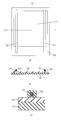
- FIG. 5 shows a schematic configuration diagram of a polymer heating element according to Embodiment 7 of the present invention
- FIG. 5 (a) is a plan view
- FIG. 5 (b) is an XY in FIG. 5 (a).
- Sectional drawing and FIG.5 (c) are the enlarged views of the electrode and electroconductive part enclosed with the broken-line part in FIG.5 (b).
- the structure of the heat generating body 51 is as follows.
- the polymer heating element 51 includes a pair of electrodes 53 and 53 ′, a polymer resistor 54, and conductive layers 55 and 55 ′ on an electrically insulating substrate 52.
- the electrically insulating substrate 52 is a needle punch type made of polyester fiber, and a nonwoven fabric impregnated with a flame retardant can be used.
- the polymer resistor 54 is disposed by thermal fusion, and then the electrodes 53 and 53 ′ previously coated with the conductive layers 55 and 55 ′ may be in direct contact with the electrodes 53 and 53 ′.
- the polymer heating elements 51 were obtained by thermally fusing the conductive layers 55 and 55 ′ so as not to be present.
- the electrodes 53 and 53 ' were obtained by twisting 19 tin-plated copper wires having a diameter of 0.06 mm.
- a lead wire for supplying power to the electrodes 53 and 53 ' is omitted.
- a kneaded material was prepared according to the following materials and procedures, and then processed into a film by calendering.
- the polymer resistor 54 includes, as a crystalline resin, 30 parts of an ethylene / methacrylic acid copolymer (trade name “Aklift CM5021”, melting point 67 ° C., manufactured by Sumitomo Chemical Co., Ltd.), an ethylene / methacrylic acid copolymer. 30 parts of a polymer (trade name “Nucleel N1560”, melting point 90 ° C., manufactured by Mitsui DuPont Polychemical Co., Ltd.), a metal coordination product of ethylene / methacrylic acid copolymer (trade name “Himiran 1702”, melting point 90 And 40 parts of Mitsui DuPont Polychemica Co., Ltd.).
- styrene thermoplastic elastomer (trade name “Tuftec M1943”), 40% by weight, manufactured by Asahi Kasei Engineering Co., Ltd., carbon black (trade name “# 10B”, primary particle diameter 75 nm, Mitsubishi Chemical) Co., Ltd.) 45% by weight, tungsten carbide (Izawa Metal Co., Ltd.) 13% by weight, and a mixture of an alkyl methacrylate / alkyl acrylate copolymer and a tetrafluoroethylene copolymer as a melt tension improver.
- a kneaded product B was prepared from 2% by weight (trade name “METABBRENE A3000”, manufactured by Mitsubishi Rayon Co., Ltd.).
- the conductive layers 55 and 55 ′ include, as resin components, 17% by weight of an ethylene-methacrylate copolymer (trade name “CG4002”, manufactured by Sumitomo Chemical Co., Ltd.) and an ethylene copolymer (trade name “ACRIFTH WH206” (ethylene- Methyl methacrylate copolymer, Sumitomo Mitsui Chemicals Co., Ltd.
- conductive whisker (trade name “FTL-110”, acicular titanium oxide, manufactured by Ishihara Sangyo Co., Ltd.) 38 weight %, Carbon black (trade name “Furness Black # 10B”, particle diameter 84 nm, manufactured by Mitsubishi Chemical Corporation), 12% by weight, carbon black (trade name “Printex L”, primary particle diameter 21 nm, manufactured by Degussa) 12% by weight, flame retardant (trade name “Reophos RDP”, phosphate ester liquid flame retardant, manufactured by Ajinomoto Co., Inc.) 10% by weight, reactive additive (Trade name “Plenact KR44”, titanate coupling agent, Ajinomoto Fine Techno Co., Ltd.) 2% by weight, as melt tension improver (trade name “Metablene A-3000”, Mitsubishi Rayon Co., Ltd.) 2% by weight A kneaded product was obtained by co-extrusion with the one obtained by twisting 19 metal wires (diameter
- the specific resistance of the conductive layer is 1 ⁇ ⁇ cm
- the PTC characteristic is that the resistance value ratio of 80 ° C. to the resistance value of 20 ° C. is 1.8, the resistance value ratio of the polymer resistor to the resistance value of the conductive layer at 80 ° C. was 2.0.
- the polymer heating element 51 constituting the planar heating element has a base member 52 side on a seat portion 7 and a backrest 8 which are seat devices 6 of an automobile as a heater for seat heating. It is used as an upper part.
- Ear portions extension portions of the base material 52 are provided to be suspended at the central portion and the peripheral portion in order to correspond to the suspended portions (not shown) of the seat portion 7 and the backrest 8, but are omitted here. Yes.
- the seat 7 and the backrest 8 to which such a polymer heating element 51 is attached are generally deformed when a load is applied by a human body seated on the seat, such as a urethane pad that is restored when the load is no longer applied.
- a seat base 9 and a seat skin 10 are provided. Therefore, the polymer heating element 51, which is a thin sheet heating element that is attached to the seat 7 and the seat base 9 of the backrest 8 with the polymer resistor 54 side and the base 52 side attached to the seat skin 10, is also provided.
- a similar deformation must be made corresponding to the deformation of the seat 7 and the backrest 8 described above.
- the electrodes 53 and 53 ′ are arranged such that a wide pair (electrically positive side and negative side) is arranged along the outer side in the longitudinal direction of the polymer heating element 51 so as to be opposed to each other, and come into contact therewith.
- a current flows through the polymer resistor 54 through the disposed conductive layers 55 and 55 'to generate heat.
- the polymer resistor 54 has a PTC characteristic, and when the temperature rises, the resistance value rises, and has a self-temperature adjusting function so as to reach a predetermined temperature, so that temperature control is unnecessary. It has a function as a highly safe planar heating element.
- the seating feeling can be satisfied by the fact that there is no squeaking like paper and has the same elongation characteristics as the seat skin material, that is, a load of 7 kgf or less for 5% elongation.
- a tube heater that uses a heating element requires a temperature controller and controls the heat generation temperature by controlling energization by ON-OFF control.
- the heater wire temperature when ON is increased to about 80 ° C., it is necessary to arrange the heater wire at a certain distance from the seat skin material.
- the heating temperature is high. Since it is self-controlled within the range of 40 ° C. to 50 ° C., it can be placed close to the seat skin material. Since the heat generation temperature is low and it is in the vicinity of the seat, it is possible to realize energy saving by being able to reduce heat loss and heat dissipation loss to the outside.
- flame retardancy can be realized by using a flame retardant nonwoven fabric for the electrically insulating substrate 52 and blending a flame retardant with the polymer resistor 54 and the conductive layers 55 and 55 '.
- Flame retardancy is the automotive interior material flame retardant standard FMVSS302 (single fire extinguishing as well as non-flammability with horizontal ignition, or if the burning speed between marked lines is 80 mm / min or less It has been confirmed that it can be satisfied if the amount of the flame retardant is at least 10% by weight.
- the polymer heating element obtained in this embodiment was subjected to a standing test in an 80 ° C. furnace, a standing test in a 150 ° C. furnace, and a heat cycle test at ⁇ 20 ° C. and 50 ° C.
- the resistance value change rate was within 30% of the initial value after 500 hours, 200 hours and 200 times, respectively.
- the reason for this was considered to be that the crystalline resin itself and the bonding between the crystalline resin and the conductor were attempted by a crosslinking reaction with the reactive resin.
- the details of the mechanism are currently unknown, but are presumed as follows.
- the conductor is required to achieve a predetermined resistance value with the smallest possible addition amount, but such a conductor is generally called conductive carbon black, and has a primary particle diameter of about 20 nm or less and a structure. (It is an aggregate of primary particles such as a bunch of coral, which is correlated with oil absorption.) On the other hand, such conductive carbon black exhibits PTC characteristics. It had the disadvantage of being difficult to do.
- a conductor such as graphite has a larger particle diameter than carbon black and has a layered structure such as a scale, and a conductor such as a metal or ceramic has a large particle diameter and is amorphous.
- the inventors have obtained as knowledge that they have excellent electrical conductivity (small volume resistivity (one hundredth or less of carbon or graphite)).
- the thickness is about 100 microns or less
- the sheet resistance is 400 ⁇ / ⁇ or less
- the specific resistance is 3 ⁇ ⁇ cm or less
- a resistance composition in which the ratio of the resistance value at 50 ° C. to the resistance value at 20 ° C. is 1.5 or more and the ratio of the resistance value at 80 ° C. to the resistance value at 20 ° C. is 5 or more in the resistance value change ratio with respect to temperature. I was able to.
- the conductor is formed using a whisker shape, it may be spherical or other rug shape.
- the electrodes 53 and 53 ′ are arranged on the polymer resistor 54 via the conductive layers 55 and 55 ′. It does not matter.
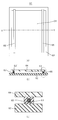
- FIG. 6 shows a schematic configuration diagram of a polymer heating element according to Embodiment 8 of the present invention.
- FIG. 6 (a) is a plan view
- FIG. 6 (b) is an XY in FIG. 6 (a).
- Sectional drawing and FIG.6 (c) are the enlarged views of the electrode and electroconductive part enclosed with the broken-line part in FIG.6 (b).
- the structure of the heating element 61 is as follows.
- the polymer heating element 61 includes a pair of electrodes 63 and 63 ′, a polymer resistor 64, and conductive layers 65 and 65 ′ on an electrically insulating substrate 62.
- the electrically insulating base material 62 is a needle punch type made of polyester fiber, and a nonwoven fabric impregnated with a flame retardant can be used.
- the electrodes 63 and 63 ′ previously coated with the conductive layers 65 and 65 ′ are electrically insulated from the electrodes 63 and 63 ′ so that the electrodes 63 and 63 ′ and the polymer resistor 64 are not in direct contact with each other.
- the polymer resistor 64 was heat-sealed to the polymer resistor 64 while maintaining a predetermined interval between the polymer resistor 64 and the polymer heating element 61 was obtained. At this time, the electrodes 63 and 63 'are obtained by twisting 19 silver-copper alloy wires having a diameter of 0.06 mm.
- the polymer resistor 64 is illustrated as being separated from the electrically insulating substrate 62, but in practice, the distance between the electrodes 63 and 63 ′ is sufficiently wide (at least 50 mm, preferably 100 mm to about 200 mm) and the conductive layers 65 and 65 'are thin (at least 0.01 mm or more, preferably about 0.1 to 0.5 mm), so that they are sufficiently heat-sealed on the electrically insulating substrate. It will be.
- the polymer resistor 64 was processed by the same method as in the seventh embodiment.
- the conductive layers 65 and 65 ′ have, as a resin component, an ethylene vinyl acetate copolymer (trade name “Evaflex EV150”, manufactured by Mitsui DuPont Polychemical Co., Ltd.) 21% by weight and a functional group exhibiting metal affinity.
- an ethylene vinyl acetate copolymer (trade name “Evaflex EV150”, manufactured by Mitsui DuPont Polychemical Co., Ltd.) 21% by weight and a functional group exhibiting metal affinity.
- a conductive whisker (trade name “FTL-110”, needle-shaped) containing 9% by weight of a resin (trade name “Tuftec M1943” (modified type of hydrogenated styrene-based thermoplastic elastomer, manufactured by Asahi Kasei Corporation)) Titanium oxide, manufactured by Ishihara Sangyo Co., Ltd.) 40% by weight, carbon black (trade name “Furness Black # 10B”, particle size 84 nm, manufactured by Mitsubishi Chemical Co., Ltd.) 15% by weight, as a flame retardant (trade name “Reophos RDP” "Phosphate ester liquid flame retardant, manufactured by Ajinomoto Co., Inc.” 10% by weight, as a reactive additive (trade name “Plenact KR44”, titanate bracket A kneaded material was obtained with 5% by weight of a ring agent, Ajinomoto Fine Techno Co., Ltd.
- a resin trade name “Tuftec M1943” (modified type of
- Electrodes 63 and 63 were obtained by twisting 19 metal wires (diameter 0.06 mm) made of a silver-copper alloy. Co-extrusion molding was performed to obtain a conductive coated electrode in which the electrode portion and the conductive layer portion were integrated.
- the specific resistance of the conductive layer is 2 ⁇ ⁇ cm
- the PTC characteristic is that the resistance value ratio of 80 ° C. to the resistance value of 20 ° C. is 2.5, the resistance value ratio of the polymer resistor to the resistance value of the conductive layer at 80 ° C. was 1.5.
- the polymer resistor 64 has PTC characteristics, and when the temperature rises, the resistance value rises, and has a self-temperature adjustment function so as to reach a predetermined temperature, and temperature control is unnecessary. It has a function as a highly safe planar heating element.
- a car seat heater of a planar heating element incorporated in an automobile seat device it can satisfy a seating feeling and flame retardancy.
- the seating feeling can be satisfied by the fact that there is no squeaking like paper and the same elongation characteristics as the seat skin material, that is, a load of 7 kgf or less for 5% elongation.
- a tube heater that uses a heating element requires a temperature controller and controls the heat generation temperature by controlling energization by ON-OFF control.
- the heater wire temperature when ON is increased to about 80 ° C., it is necessary to arrange the heater wire at a certain distance from the seat skin material.
- the heating temperature is high. Since it is self-controlled within the range of 40 ° C. to 50 ° C., it can be placed close to the seat skin material. Since the heat generation temperature is low and it is in the vicinity of the seat, it is possible to realize energy saving by being able to reduce heat loss and heat dissipation loss to the outside.
- flame retardancy can be realized by using a flame retardant nonwoven fabric for the electrically insulating substrate 62 and blending a flame retardant with the polymer resistor 64 and the conductive layers 65 and 65 '.
- Flame retardancy is the automotive interior material flame retardant standard FMVSS302 (single fire extinguishing as well as non-flammability with horizontal ignition, or if the burning speed between marked lines is 80 mm / min or less It has been confirmed that it can be satisfied if the amount of the flame retardant is at least 10% by weight.
- the polymer heating element obtained in this embodiment was subjected to a standing test in an 80 ° C. furnace, a standing test in a 150 ° C. furnace, and a heat cycle test at ⁇ 20 ° C. and 50 ° C.
- the resistance value change rate was within 30% of the initial value after 500 hours, 200 hours and 200 times, respectively.
- the reason for this was considered to be that the crystalline resin itself and the bonding between the crystalline resin and the conductor were attempted by a crosslinking reaction with the reactive resin.
- the electrodes 63 and 63 ′ are disposed under the polymer resistor 64 via the conductive layers 65 and 65 ′. It may be an arrangement.
- the protective layer on the upper side of the resistor is omitted, but the upper protective layer may be provided in consideration of water resistance and wear resistance. Absent.
- Japanese Patent Application No. 2008-035583 Japanese patent application filed on October 16, 2008
- Japanese Patent Application No. 2008-267014 Japanese patent application filed on December 12, 2008.
- Japanese Patent Application No. 2008-316382 Japanese patent application filed on December 18, 2008
- the polymer heating element according to the present invention has high flexibility and high reliability, and can be used as a heating element for heating a vehicle seat device, a handle device, and other parts. is there.
Abstract
Description
2、52、62 電気絶縁性基材
3、3’、53、53’、63、63’ 電極
4、54、64 高分子抵抗体
5、5’、55、55’、65、65’ 導電層
6 座席装置
7 座部
8 背もたれ
9 座席基材
10 座席表皮 1, 51, 61
図1,2において、高分子発熱体1は、電気絶縁性基材2上に、一対の電極3,3’、高分子抵抗体4、及び導電層5,5’を含んで構成される。 (Embodiment 1)
1 and 2, the
本発明の実施の形態2における高分子発熱体においては、実施の形態1と同様の構造のものを用いた。 (Embodiment 2)
As the polymer heating element in the second embodiment of the present invention, the one having the same structure as that in the first embodiment was used.
本発明の実施の形態3における高分子発熱体においては、実施の形態1と同様の構造のものを用いた。 (Embodiment 3)
As the polymer heating element in the third embodiment of the present invention, one having the same structure as that in the first embodiment was used.
本発明の実施の形態4における高分子発熱体においては、図1,2に示した実施の形態1と同様の構造のものを用いた。 (Embodiment 4)
As the polymer heating element according to the fourth embodiment of the present invention, the one having the same structure as that of the first embodiment shown in FIGS.
実施の形態5における高分子発熱体においては、実施の形態4と同様の構造のものを用いた。 (Embodiment 5)
The polymer heating element in the fifth embodiment has the same structure as that in the fourth embodiment.
実施の形態6における高分子発熱体においては、実施の形態4と同様の構造のものを用いた。 (Embodiment 6)
As the polymer heating element in the sixth embodiment, one having the same structure as in the fourth embodiment was used.
図5は、本発明の実施の形態7における高分子発熱体の概略構成図を示すものであり、図5(a)は平面図、図5(b)は図5(a)におけるX-Y断面図、図5(c)は図5(b)における破線部で囲んだ電極および導電部の拡大図である。図5において、発熱体51の構成は以下の通りである。高分子発熱体51は、電気絶縁性基材52上に、一対の電極53、53’及び、高分子抵抗体54、及び導電層55、55’を含む。 (Embodiment 7)
FIG. 5 shows a schematic configuration diagram of a polymer heating element according to
図6は、本発明の実施の形態8における高分子発熱体の概略構成図を示すものであり、図6(a)は平面図、図6(b)は図6(a)におけるX-Y断面図、図6(c)は図6(b)における破線部で囲んだ電極および導電部の拡大図である。図6において、発熱体61の構成は以下の通りである。高分子発熱体61は、電気絶縁性基材62上に、一対の電極63、63’及び、高分子抵抗体64、及び導電層65、65’を含む。 (Embodiment 8)
FIG. 6 shows a schematic configuration diagram of a polymer heating element according to
Claims (18)
- 電気絶縁性基材と、前記電気絶縁性基材上に配設された複数本の金属細線で構成される少なくとも一対の電極と、前記一対の電極とは直接接触しないPTC特性を有する高分子抵抗体と、前記電極と前記高分子抵抗体との双方に接触する導電層とを具備し、前記導電層が少なくとも樹脂成分と導電体成分と添加剤成分とを含む高分子発熱体。 A polymer resistor having PTC characteristics in which the electrically insulating base material, at least a pair of electrodes composed of a plurality of thin metal wires disposed on the electrically insulating base material, and the pair of electrodes are not in direct contact with each other And a polymer heating element comprising a conductive layer in contact with both the electrode and the polymer resistor, wherein the conductive layer includes at least a resin component, a conductor component, and an additive component.
- 前記導電層の樹脂成分が、金属親和性を示す官能基を有する請求項1記載の高分子発熱体。 The polymer heating element according to claim 1, wherein the resin component of the conductive layer has a functional group exhibiting metal affinity.
- 電気絶縁性基材と、前記電気絶縁性基材上に配設された複数本の金属細線で構成される少なくとも一対の電極と、前記一対の電極とは直接接触しないPTC特性を有する高分子抵抗体と、前記電極と前記高分子抵抗体との双方に接触する導電層とを具備し、前記導電層が少なくとも架橋性樹脂成分と導電体成分とを含む高分子発熱体。 A polymer resistor having PTC characteristics in which the electrically insulating base material, at least a pair of electrodes composed of a plurality of thin metal wires disposed on the electrically insulating base material, and the pair of electrodes are not in direct contact with each other And a polymer heating element comprising a conductive layer in contact with both the electrode and the polymer resistor, wherein the conductive layer includes at least a crosslinkable resin component and a conductor component.
- 前記導電層が、架橋性樹脂成分と導電体成分と溶融張力向上剤成分とを含有する請求項3記載の高分子発熱体。 The polymer heating element according to claim 3, wherein the conductive layer contains a crosslinkable resin component, a conductor component, and a melt tension improver component.
- 前記導電層の架橋性樹脂成分が、反応性添加剤により架橋されている請求項3または4記載の高分子発熱体。 The polymer heating element according to claim 3 or 4, wherein the crosslinkable resin component of the conductive layer is crosslinked with a reactive additive.
- 前記導電層の導電体成分の重量比率が、導電層重量に対して50重量%以上80重量%以下含まれる請求項1または3記載の高分子発熱体。 The polymer heating element according to claim 1 or 3, wherein a weight ratio of the conductor component of the conductive layer is 50 wt% to 80 wt% with respect to the weight of the conductive layer.
- 前記導電層の導電体成分が、カーボンブラック、グラファイト、カーボンナノチューブ、カーボン繊維、導電性セラミック繊維、導電性ウィスカ、金属繊維、導電性無機酸化物、導電性ポリマー繊維の少なくとも一種から選ばれる導電体からなる請求項1、3、6のいずれか1項に記載の高分子発熱体。 The conductor component of the conductive layer is selected from at least one of carbon black, graphite, carbon nanotube, carbon fiber, conductive ceramic fiber, conductive whisker, metal fiber, conductive inorganic oxide, and conductive polymer fiber. The polymer heating element according to any one of claims 1, 3, and 6.
- 前記導電層の添加剤成分が、リン系、窒素系、シリコーン系の少なくとも1種の難燃剤を含有する請求項1記載の高分子発熱体。 The polymer heating element according to claim 1, wherein the additive component of the conductive layer contains at least one flame retardant of phosphorus, nitrogen and silicone.
- 前記導電層の比抵抗が0.01~500Ω・cmである請求項1~8のいずれか1項に記載の高分子発熱体。 The polymer heating element according to any one of claims 1 to 8, wherein a specific resistance of the conductive layer is 0.01 to 500 Ω · cm.
- 電気絶縁性基材と、前記電気絶縁性基材上に配設されたPTC特性を有する高分子抵抗体と、前記高分子抵抗体とは直接接触しない複数本の金属細線で構成される少なくとも一対の電極と、前記高分子抵抗体と前記電極との双方に接触する導電層から形成されてなる高分子発熱体において、前記導電層がPTC特性を示す高分子発熱体。 At least a pair of an electrically insulating substrate, a polymer resistor having PTC characteristics disposed on the electrically insulating substrate, and a plurality of fine metal wires not in direct contact with the polymer resistor And a polymer heating element formed of a conductive layer in contact with both the polymer resistor and the electrode, wherein the conductive layer exhibits PTC characteristics.
- 前記高分子抵抗体と前記電極との間隔が0.01mm~3mmの範囲である請求項10記載の高分子発熱体。 The polymer heating element according to claim 10, wherein an interval between the polymer resistor and the electrode is in a range of 0.01 mm to 3 mm.
- 前記導電層がPTC特性として、80℃における抵抗値が20℃における抵抗値に対して10倍以下となる請求項10記載の高分子発熱体。 The polymer heating element according to claim 10, wherein the conductive layer has a PTC characteristic, and a resistance value at 80 ° C is 10 times or less than a resistance value at 20 ° C.
- 前記導電層の比抵抗に対する前記高分子抵抗体の比抵抗の比率が80℃以下の温度領域において100倍以下となる請求項10~12のいずれか1項に記載の高分子発熱体。 The polymer heating element according to any one of claims 10 to 12, wherein a ratio of a specific resistance of the polymer resistor to a specific resistance of the conductive layer is 100 times or less in a temperature region of 80 ° C or less.
- 前記導電層が前記電極に対して平行である請求項10~13のいずれか1項に記載の高分子発熱体。 The polymer heating element according to any one of claims 10 to 13, wherein the conductive layer is parallel to the electrode.
- 前記導電層の組成物と前記電極を構成する金属細線とを共押出成形してなる請求項10~14のいずれか1項に記載の高分子発熱体。 The polymer heating element according to any one of claims 10 to 14, wherein the composition of the conductive layer and a metal fine wire constituting the electrode are coextruded.
- 前記電極が、錫めっき銅、銀含有銅、銀銅合金の少なくとも1種を含む金属細線である請求項1、3、10のいずれか1項に記載の高分子発熱体。 The polymer heating element according to any one of claims 1, 3, and 10, wherein the electrode is a fine metal wire containing at least one of tin-plated copper, silver-containing copper, and a silver-copper alloy.
- 前記電気絶縁性基材が樹脂フィルム、織布、不織布の少なくとも1種からなる請求項1、3、10のいずれか1項に記載の高分子発熱体。 The polymer heating element according to any one of claims 1, 3, and 10, wherein the electrically insulating substrate comprises at least one of a resin film, a woven fabric, and a nonwoven fabric.
- 請求項1~17のいずれか1項記載の高分子発熱体を搭載した自動車用座席装置。 An automotive seat device equipped with the polymer heating element according to any one of claims 1 to 17.
Priority Applications (5)
| Application Number | Priority Date | Filing Date | Title |
|---|---|---|---|
| EP09711851.7A EP2247157A4 (en) | 2008-02-18 | 2009-02-04 | Polymer heating element |
| CN200980105370.9A CN101946557B (en) | 2008-02-18 | 2009-02-04 | Polymer heating element |
| CA2715485A CA2715485A1 (en) | 2008-02-18 | 2009-02-04 | Polymer heating element |
| US12/867,862 US8519305B2 (en) | 2008-02-18 | 2009-02-04 | Polymer heating element |
| JP2009554208A JPWO2009104361A1 (en) | 2008-02-18 | 2009-02-04 | Polymer heating element |
Applications Claiming Priority (6)
| Application Number | Priority Date | Filing Date | Title |
|---|---|---|---|
| JP2008-035583 | 2008-02-18 | ||
| JP2008035583 | 2008-02-18 | ||
| JP2008-267014 | 2008-10-16 | ||
| JP2008267014 | 2008-10-16 | ||
| JP2008-316382 | 2008-12-12 | ||
| JP2008316382 | 2008-12-12 |
Publications (1)
| Publication Number | Publication Date |
|---|---|
| WO2009104361A1 true WO2009104361A1 (en) | 2009-08-27 |
Family
ID=40985250
Family Applications (1)
| Application Number | Title | Priority Date | Filing Date |
|---|---|---|---|
| PCT/JP2009/000434 WO2009104361A1 (en) | 2008-02-18 | 2009-02-04 | Polymer heating element |
Country Status (7)
| Country | Link |
|---|---|
| US (1) | US8519305B2 (en) |
| EP (1) | EP2247157A4 (en) |
| JP (1) | JPWO2009104361A1 (en) |
| KR (1) | KR20100115762A (en) |
| CN (1) | CN101946557B (en) |
| CA (1) | CA2715485A1 (en) |
| WO (1) | WO2009104361A1 (en) |
Families Citing this family (28)
| Publication number | Priority date | Publication date | Assignee | Title |
|---|---|---|---|---|
| US7306283B2 (en) | 2002-11-21 | 2007-12-11 | W.E.T. Automotive Systems Ag | Heater for an automotive vehicle and method of forming same |
| US8388056B2 (en) * | 2009-05-08 | 2013-03-05 | ReAnna Gayle Smith | Heated collapsible article of furniture |
| DE102009059995A1 (en) * | 2009-12-21 | 2011-06-22 | W.E.T. Automotive Systems AG, 85235 | Electric heater |
| US8702164B2 (en) | 2010-05-27 | 2014-04-22 | W.E.T. Automotive Systems, Ltd. | Heater for an automotive vehicle and method of forming same |
| DE102011114949A1 (en) | 2010-10-19 | 2012-04-19 | W.E.T. Automotive Systems Ag | Electrical conductor |
| US9204496B2 (en) | 2010-11-08 | 2015-12-01 | Panasonic Intellectual Property Management Co., Ltd. | Planar heating element and manufacturing method for same |
| DE102012000977A1 (en) | 2011-04-06 | 2012-10-11 | W.E.T. Automotive Systems Ag | Heating device for complex shaped surfaces |
| EP2720746B1 (en) | 2011-06-16 | 2020-01-22 | ResMed Pty Ltd | Humidifier |
| DE102011121979A1 (en) | 2011-09-14 | 2012-11-22 | W.E.T. Automotive Systems Ag | Tempering equipment for use in handle piece of shifting knob of gear shift of vehicle for keeping hand of user at moderate temperature, has heating device provided with heating resistor, and strand inserted into recesses of carrier |
| US10201039B2 (en) | 2012-01-20 | 2019-02-05 | Gentherm Gmbh | Felt heater and method of making |
| JP5678914B2 (en) * | 2012-03-21 | 2015-03-04 | 豊田合成株式会社 | In-vehicle heater element |
| DE202013003491U1 (en) | 2012-06-18 | 2013-09-20 | W.E.T. Automotive Systems Ag | Sheet with electrical function |
| DE102012017047A1 (en) | 2012-08-29 | 2014-03-06 | W.E.T. Automotive Systems Ag | Electric heater |
| CN103832302B (en) * | 2012-11-22 | 2016-06-08 | 清华大学 | Automotive seat |
| DE102012024903A1 (en) | 2012-12-20 | 2014-06-26 | W.E.T. Automotive Systems Ag | Flat structure with electrical functional elements |
| DE112014002248T5 (en) | 2013-05-02 | 2016-01-28 | Gentherm Canada Ltd. | Liquid-resistant heating element |
| DE102013105334A1 (en) * | 2013-05-24 | 2014-11-27 | Benecke-Kaliko Aktiengesellschaft | Electrically conductive connection |
| US10134502B2 (en) | 2014-07-18 | 2018-11-20 | Kim Edward Elverud | Resistive heater |
| EP4120796A3 (en) * | 2015-01-06 | 2023-05-03 | Battelle Memorial Institute | Uniform heat distribution in resistive heaters for anti-icing and de-icing |
| EP3245844B1 (en) | 2015-01-12 | 2020-05-27 | Laminaheat Holding Ltd. | Fabric heating element |
| WO2017068416A1 (en) | 2015-10-19 | 2017-04-27 | Laminaheat Holding Ltd. | Laminar heating elements with customized or non-uniform resistance and/or irregular shapes, and processes for manufacture |
| GB2546076B (en) * | 2016-01-06 | 2020-04-08 | Ford Global Tech Llc | Vehicle furniture |
| US10375765B2 (en) * | 2016-04-15 | 2019-08-06 | Hewlett-Packard Development Company, L.P. | 3-dimensional printed load cell parts |
| DE102017001097A1 (en) | 2017-02-07 | 2018-08-09 | Gentherm Gmbh | Electrically conductive foil |
| CN109413774B (en) * | 2018-10-31 | 2022-03-08 | 宁波石墨烯创新中心有限公司 | Graphene electrothermal film, preparation method thereof and electrothermal product |
| CN109618427B (en) * | 2018-12-10 | 2022-03-04 | 沈阳化工大学 | Preparation method of flexible carbon crystal electric heating film |
| USD911038S1 (en) | 2019-10-11 | 2021-02-23 | Laminaheat Holding Ltd. | Heating element sheet having perforations |
| KR102265966B1 (en) * | 2019-10-16 | 2021-06-17 | 지유엠아이씨 주식회사 | Planar heating element in which a conductor having a double structure and a conductor having a double structure are formed in a conductive fabric that realizes a heat generating function |
Citations (3)
| Publication number | Priority date | Publication date | Assignee | Title |
|---|---|---|---|---|
| JPH01186782A (en) * | 1988-01-14 | 1989-07-26 | Matsushita Electric Works Ltd | Heating body |
| JP2002371699A (en) | 2001-06-14 | 2002-12-26 | Matsushita Electric Ind Co Ltd | Tatami mat floor heating |
| WO2007110976A1 (en) * | 2006-03-29 | 2007-10-04 | Matsushita Electric Industrial Co., Ltd. | Sheet heating element and seat making use of the same |
Family Cites Families (6)
| Publication number | Priority date | Publication date | Assignee | Title |
|---|---|---|---|---|
| JPH07111897B2 (en) * | 1991-12-24 | 1995-11-29 | 由喜子 城尾 | Method of connecting electrode formed on conductive film and lead wire |
| JP3029172B2 (en) * | 1993-08-06 | 2000-04-04 | 日立電線株式会社 | Insulated wire |
| US7202444B2 (en) * | 1999-01-25 | 2007-04-10 | Illinois Tool Works Inc. | Flexible seat heater |
| JP2002075052A (en) * | 2000-08-31 | 2002-03-15 | Mitsubishi Plastics Ind Ltd | Conductive resin composition and sheet |
| CN100536040C (en) * | 2002-06-19 | 2009-09-02 | 松下电器产业株式会社 | Flexible PTC heating element and preparation method thereof |
| US7675004B2 (en) * | 2004-03-12 | 2010-03-09 | Panasonic Corporation | Heating element and production method thereof |
-
2009
- 2009-02-04 KR KR1020107017972A patent/KR20100115762A/en not_active Application Discontinuation
- 2009-02-04 JP JP2009554208A patent/JPWO2009104361A1/en active Pending
- 2009-02-04 EP EP09711851.7A patent/EP2247157A4/en not_active Withdrawn
- 2009-02-04 US US12/867,862 patent/US8519305B2/en active Active
- 2009-02-04 CN CN200980105370.9A patent/CN101946557B/en active Active
- 2009-02-04 WO PCT/JP2009/000434 patent/WO2009104361A1/en active Application Filing
- 2009-02-04 CA CA2715485A patent/CA2715485A1/en not_active Abandoned
Patent Citations (3)
| Publication number | Priority date | Publication date | Assignee | Title |
|---|---|---|---|---|
| JPH01186782A (en) * | 1988-01-14 | 1989-07-26 | Matsushita Electric Works Ltd | Heating body |
| JP2002371699A (en) | 2001-06-14 | 2002-12-26 | Matsushita Electric Ind Co Ltd | Tatami mat floor heating |
| WO2007110976A1 (en) * | 2006-03-29 | 2007-10-04 | Matsushita Electric Industrial Co., Ltd. | Sheet heating element and seat making use of the same |
Non-Patent Citations (1)
| Title |
|---|
| See also references of EP2247157A4 * |
Also Published As
| Publication number | Publication date |
|---|---|
| CA2715485A1 (en) | 2009-08-27 |
| EP2247157A1 (en) | 2010-11-03 |
| CN101946557B (en) | 2014-04-16 |
| JPWO2009104361A1 (en) | 2011-06-16 |
| EP2247157A4 (en) | 2015-07-08 |
| CN101946557A (en) | 2011-01-12 |
| US20100326976A1 (en) | 2010-12-30 |
| KR20100115762A (en) | 2010-10-28 |
| US8519305B2 (en) | 2013-08-27 |
Similar Documents
| Publication | Publication Date | Title |
|---|---|---|
| WO2009104361A1 (en) | Polymer heating element | |
| JP5201137B2 (en) | Polymer resistor | |
| JP5217411B2 (en) | Polymer heating element | |
| JP4877066B2 (en) | Resistor composition and planar heating element using the same | |
| JPWO2007110976A1 (en) | Sheet heating element and seat using the same | |
| JP2010020989A (en) | Polymer heating element | |
| JP2008293671A (en) | Resistor composition, and surface heat generating body using this | |
| JP2011181316A (en) | Heater unit | |
| JP2009199794A (en) | Planar heating element | |
| JP5125581B2 (en) | Planar heating element | |
| JP2012227034A (en) | Planar heating element | |
| JP2009266631A (en) | Polymer exothermic body | |
| JP2009176549A (en) | Polymer heating element | |
| JP2008293670A (en) | Resistor composition, and surface heat generating body using this | |
| CN101578912B (en) | PTC resistor | |
| JP2010257683A (en) | Planar heating element, and method of manufacturing the same | |
| JP5126156B2 (en) | Planar heating element | |
| JP2010244971A (en) | Surface heating body | |
| JP4639653B2 (en) | Flexible heating element | |
| JP2011003328A (en) | Polymer heating element | |
| JP2010129425A (en) | Resistive element composition and heating element using this | |
| JP2010132055A (en) | Vehicle heater | |
| JP2006004646A5 (en) | ||
| JP2009009706A (en) | Planar heating element | |
| JP2010097793A (en) | Planar heating element |
Legal Events
| Date | Code | Title | Description |
|---|---|---|---|
| WWE | Wipo information: entry into national phase |
Ref document number: 200980105370.9 Country of ref document: CN |
|
| 121 | Ep: the epo has been informed by wipo that ep was designated in this application |
Ref document number: 09711851 Country of ref document: EP Kind code of ref document: A1 |
|
| WWE | Wipo information: entry into national phase |
Ref document number: 2009554208 Country of ref document: JP |
|
| WWE | Wipo information: entry into national phase |
Ref document number: 2715485 Country of ref document: CA |
|
| ENP | Entry into the national phase |
Ref document number: 20107017972 Country of ref document: KR Kind code of ref document: A |
|
| REEP | Request for entry into the european phase |
Ref document number: 2009711851 Country of ref document: EP |
|
| WWE | Wipo information: entry into national phase |
Ref document number: 12867862 Country of ref document: US Ref document number: 2009711851 Country of ref document: EP |
|
| NENP | Non-entry into the national phase |
Ref country code: DE |