WO2009102013A1 - Dispositif de détection de vecteur de mouvement - Google Patents
Dispositif de détection de vecteur de mouvement Download PDFInfo
- Publication number
- WO2009102013A1 WO2009102013A1 PCT/JP2009/052403 JP2009052403W WO2009102013A1 WO 2009102013 A1 WO2009102013 A1 WO 2009102013A1 JP 2009052403 W JP2009052403 W JP 2009052403W WO 2009102013 A1 WO2009102013 A1 WO 2009102013A1
- Authority
- WO
- WIPO (PCT)
- Prior art keywords
- edge
- area
- frame
- feature
- value
- Prior art date
Links
Images


Classifications
-
- H—ELECTRICITY
- H04—ELECTRIC COMMUNICATION TECHNIQUE
- H04N—PICTORIAL COMMUNICATION, e.g. TELEVISION
- H04N19/00—Methods or arrangements for coding, decoding, compressing or decompressing digital video signals
- H04N19/50—Methods or arrangements for coding, decoding, compressing or decompressing digital video signals using predictive coding
- H04N19/503—Methods or arrangements for coding, decoding, compressing or decompressing digital video signals using predictive coding involving temporal prediction
- H04N19/51—Motion estimation or motion compensation
- H04N19/57—Motion estimation characterised by a search window with variable size or shape
-
- H—ELECTRICITY
- H04—ELECTRIC COMMUNICATION TECHNIQUE
- H04N—PICTORIAL COMMUNICATION, e.g. TELEVISION
- H04N19/00—Methods or arrangements for coding, decoding, compressing or decompressing digital video signals
- H04N19/10—Methods or arrangements for coding, decoding, compressing or decompressing digital video signals using adaptive coding
- H04N19/134—Methods or arrangements for coding, decoding, compressing or decompressing digital video signals using adaptive coding characterised by the element, parameter or criterion affecting or controlling the adaptive coding
- H04N19/136—Incoming video signal characteristics or properties
- H04N19/14—Coding unit complexity, e.g. amount of activity or edge presence estimation
-
- H—ELECTRICITY
- H04—ELECTRIC COMMUNICATION TECHNIQUE
- H04N—PICTORIAL COMMUNICATION, e.g. TELEVISION
- H04N19/00—Methods or arrangements for coding, decoding, compressing or decompressing digital video signals
- H04N19/10—Methods or arrangements for coding, decoding, compressing or decompressing digital video signals using adaptive coding
- H04N19/169—Methods or arrangements for coding, decoding, compressing or decompressing digital video signals using adaptive coding characterised by the coding unit, i.e. the structural portion or semantic portion of the video signal being the object or the subject of the adaptive coding
- H04N19/17—Methods or arrangements for coding, decoding, compressing or decompressing digital video signals using adaptive coding characterised by the coding unit, i.e. the structural portion or semantic portion of the video signal being the object or the subject of the adaptive coding the unit being an image region, e.g. an object
-
- H—ELECTRICITY
- H04—ELECTRIC COMMUNICATION TECHNIQUE
- H04N—PICTORIAL COMMUNICATION, e.g. TELEVISION
- H04N19/00—Methods or arrangements for coding, decoding, compressing or decompressing digital video signals
- H04N19/42—Methods or arrangements for coding, decoding, compressing or decompressing digital video signals characterised by implementation details or hardware specially adapted for video compression or decompression, e.g. dedicated software implementation
- H04N19/43—Hardware specially adapted for motion estimation or compensation
- H04N19/433—Hardware specially adapted for motion estimation or compensation characterised by techniques for memory access
-
- H—ELECTRICITY
- H04—ELECTRIC COMMUNICATION TECHNIQUE
- H04N—PICTORIAL COMMUNICATION, e.g. TELEVISION
- H04N19/00—Methods or arrangements for coding, decoding, compressing or decompressing digital video signals
- H04N19/50—Methods or arrangements for coding, decoding, compressing or decompressing digital video signals using predictive coding
- H04N19/503—Methods or arrangements for coding, decoding, compressing or decompressing digital video signals using predictive coding involving temporal prediction
- H04N19/51—Motion estimation or motion compensation
- H04N19/537—Motion estimation other than block-based
- H04N19/54—Motion estimation other than block-based using feature points or meshes
-
- H—ELECTRICITY
- H04—ELECTRIC COMMUNICATION TECHNIQUE
- H04N—PICTORIAL COMMUNICATION, e.g. TELEVISION
- H04N19/00—Methods or arrangements for coding, decoding, compressing or decompressing digital video signals
- H04N19/50—Methods or arrangements for coding, decoding, compressing or decompressing digital video signals using predictive coding
- H04N19/503—Methods or arrangements for coding, decoding, compressing or decompressing digital video signals using predictive coding involving temporal prediction
- H04N19/51—Motion estimation or motion compensation
- H04N19/56—Motion estimation with initialisation of the vector search, e.g. estimating a good candidate to initiate a search
Definitions
- the present invention relates to a movement vector detection apparatus, and more particularly to a movement vector detection apparatus that detects main movement vectors from drawing data on a computer screen.
- drawing data of an application program executed on the server device is transferred to a terminal device on the client side through a network such as a LAN (Local Area Network) and displayed on the screen of the terminal apparatus.
- a network such as a LAN (Local Area Network)
- the load on the server device for transferring drawing data to the terminal device increases and the response time decreases. And problems such as significant restrictions on the number of connected terminal devices occur.
- a technique called a full search method is generally used to detect a movement vector and a movement area.
- a comparison is made between a template block as an image to be searched and all search windows as search targets. That is, the movement vector and the movement area are detected in units of blocks of 8 pixels ⁇ 8 pixels.
- the difference absolute value sum of the pixel values is obtained in order while scanning the search window, and a motion with a place where the difference absolute value is minimized is detected as a movement vector.
- the full search method requires a very large amount of computation. For this reason, a high-speed method is proposed in which a rough search is first performed broadly, and a narrow search is performed according to the evaluation result with high accuracy (see, for example, Patent Document 2).
- An object of the present invention is to provide a movement vector detection apparatus capable of detecting a main movement vector at high speed and with high accuracy from drawing data on a computer screen.
- the moving vector detection apparatus includes an edge extraction unit that extracts edge points from each of a current frame and a previous frame that is a frame before the current frame, and the edge extraction unit extracts the edge point.
- the edge extraction unit extracts the edge point.
- feature points that are edge points whose positional relationship with one or more other edge points in the frame is uniquely determined in the frame are extracted from each of the previous frame and the current frame.
- the movement vector detecting apparatus uses the positional relationship between two edge points as a feature amount for an edge pair that is a combination of two edge points included in a frame, and features of the current frame.
- the edge pair of the previous frame and the edge pair of the current frame, the position relationship of which is uniquely determined between the quantity and the feature quantity of the previous frame that is a frame before the current frame are feature point pairs, and the previous point in the feature point pair
- a coordinate difference between an edge point of an edge pair of a frame and an edge point of the edge pair of the current frame in the feature point pair is detected as a movement vector of a movement region from the previous frame to the current frame.
- a movement vector detection apparatus capable of detecting main movement vectors at high speed and with high accuracy from drawing data on a computer screen.
- 1 is a block diagram of a video signal encoding device according to an embodiment of the present invention. It is a flowchart which shows the flow of a process of the video signal encoding apparatus which concerns on embodiment of this invention. It is explanatory drawing of the encoding process of the video signal by the video signal encoding apparatus which concerns on embodiment of this invention. It is a block diagram of the 1st Example of a movement vector detection part. It is a flowchart which shows the flow of a process of the movement vector detection part which concerns on a 1st Example. It is explanatory drawing of the edge extraction process in the movement vector detection part which concerns on a 1st Example.
- FIG. 1 It is a figure which shows an example of the hash table of the present frame used with the movement vector detection part which concerns on a 1st Example. It is a figure which shows an example of the hash table of the previous frame used by the movement vector detection part which concerns on a 1st Example. It is a figure which shows an example of the detection result of the movement vector detection part which concerns on 1st Example. Relationship between an image obtained by plotting a pair of feature points included in a list of most frequent movement vector candidates detected by the movement vector detection unit according to the first embodiment in the previous frame and the current frame, and the estimated movement vector FIG. It is a block diagram of the 1st Example of a movement area
- an example of a video signal encoding device 100 includes an image input device 101, a data storage device 102, a data processing device 103, and a code output device 104. ing.
- the image input device 101 is a device for inputting a video signal to be encoded.
- a color video signal on a display screen of a computer (not shown) is analog-captured or digitally captured and stored in the data storage device 102.
- the captured video signal for one screen is called a frame or screen data.
- the data storage device 102 stores an encoding target frame storage unit 111 that stores a frame input from the image input device 101, and a reference frame that stores a reference frame used for encoding the frame stored in the encoding target frame storage unit 111.
- the storage unit 112 includes a work area 113 that holds various data that are appropriately referenced and updated in the process of frame encoding.
- the data processing device 103 is a device that encodes the encoding target frame stored in the data storage device 102, and includes a movement vector detection unit 121, a movement region detection unit 122, a motion compensation unit 123, and an update region detection region setting unit. 124, an update region detection unit 125, and a region encoding unit 126. Each part has the following general functions.
- the movement vector detection unit 121 has a function of detecting one main movement vector by comparing the encoding target frame with the immediately preceding frame.
- the main movement vector means a dominant one of one or more movement vectors. For example, when map scrolling and mouse cursor movement occur simultaneously on the computer screen, the movement vector by the map scroll becomes the main movement vector because most of the movement area is occupied by the map scrolling.
- the movement area detection unit 122 is the same or similar image area that exists in both the encoding target frame and the immediately preceding frame, and the movement vector detection unit 121 detects the position on the screen. It has a function of detecting an image area that changes only as a moving area.
- the motion compensation unit 123 copies the movement region detected by the movement region detection unit 122 to the movement destination indicated by the movement vector in the reference frame used for encoding the frame to be encoded, and the reference frame after the motion compensation It has the function to generate.
- the update area detection area setting unit 124 has a function of setting one or more update area detection areas on the frame.
- the update region detection unit 125 has a function of detecting, as an update region, a region where the reference frame after motion compensation is different from the encoding target frame for each update region detection region set by the update region detection region setting unit 124. .
- the region encoding unit 126 generates a code obtained by encoding the update region detected by the update region detection unit 125 as an image by an arbitrary encoding method.
- the code output device 104 is a device that reads out and outputs the code generated for the encoding target frame from the work area 113 of the data storage device 102, and is configured by, for example, a communication device that communicates with a client terminal (not shown).
- the code generated for one encoding target frame includes the update region code generated by the region encoding unit 126, the movement region information detected by the movement vector detection unit 121 and the movement region detection unit 122 (the movement source information). Area coordinates and movement vectors).
- the movement vector detection unit 121, the movement region detection unit 122, the motion compensation unit 123, the update region detection region setting unit 124, the update region detection unit 125, and the region encoding unit 126 include a computer that constitutes the data processing device 103 and its computer It can be realized with the program that operates above.
- the program is provided by being recorded on a computer-readable recording medium such as a CD-ROM, and read by the computer when the computer is started up, etc., and controls the operation of the computer, thereby realizing the above-described units on the computer.
- the image input device 101 of the video signal encoding device 100 captures a frame to be encoded and stores it as a current frame in the encoding target frame storage unit 111 of the data storage device 102 (step S101 in FIG. 2).
- the motion vector detection unit 121 compares the current frame with a frame (reference frame) that has already been encoded and stored in the reference frame storage unit 112, and detects one main motion vector. (Step S102). For example, if the movement vector 134 illustrated from the comparison between the current frame 131 and the reference frame 132 in FIG. 3 is dominant, the movement vector 134 is detected as the main movement vector. Information on the detected movement vector 134 is temporarily stored in the work area 113.
- the movement area detection unit 122 is the same or similar image area that exists in both the current frame and the reference frame,
- the image area where the position at is changed by the movement vector detected by the movement vector detection unit 121 is detected as the movement area (step S104).
- the areas 135 and 136 are detected as moving areas.
- the detected coordinate information of the moving areas 135 and 136 is temporarily stored in the work area 113.
- the motion compensation unit 123 performs motion compensation for copying the image of the movement area before movement on the reference frame to the position after movement indicated by the movement vector.
- the reference frame storage unit 112 is updated (step S106). For example, in the case of FIG. 3, the area 136 is copied to a position corresponding to the area 135 in the current frame 131 on the reference frame 132. Thereby, the reference frame 137 after motion compensation in FIG. 3 is generated.
- step S103 if the movement vector is not detected (NO in step S103), the detection of the movement area and the motion compensation are not executed. Further, even if the movement vector is detected, if the detection of the movement area fails (NO in step S105), motion compensation is not executed.
- the update area detection area setting unit 124 sets one or more update area detection areas for detecting the update area on the frame (step S107).
- the update region detection unit 125 detects a region where the reference frame is different from the current frame for each update region detection region set by the update region detection region setting unit 124 (step S108). Thereby, for example, in the case of FIG. 3, the update areas 138 and 139 are detected.
- the detected coordinate information of the update areas 138 and 139 is temporarily stored in the work area 113.
- the region encoding unit 126 generates a code obtained by encoding the update region detected by the update region detection unit 125 as an image (step S109).
- the generated code is temporarily stored in association with the coordinate information of the update area stored in the work area 113.
- the code output device 104 receives the information generated for the current frame from the work area 113 of the data storage device 102, that is, the coordinate information of each update area and its code and movement area information (coordinate information and movement vector of the movement source area). Read and output (step S110). For example, in the case of FIG. 3, the coordinate information and code of the update area 138, the coordinate information and code of the update area 139, the coordinate information of the movement area 136, and the movement vector 134 are output as code information regarding the current frame.
- the procedure is the reverse of encoding.
- the movement region 136 of the reference frame 132 is copied to the location indicated by the movement vector 134 to generate a reference frame 137 after motion compensation.
- the current frame 131 is generated by reflecting the update area 138 and the update area 139 decoded from the code information with respect to the reference frame.
- the motion compensation unit 123 can be realized by a copy unit
- the region encoding unit 126 can be realized by a known image encoding technique such as predictive encoding, transform encoding, vector quantization, entropy encoding, etc.
- the movement vector detection unit 121, the movement region detection unit 122, the update region detection region setting unit 124, and the update region detection unit 125 will be described in detail.
- the first example of the movement vector detection unit 121 includes an edge extraction unit 201, a feature point extraction unit 202, a feature point pair extraction unit 203, and a movement vector calculation unit 204. Each has the following functions in general.
- the edge extraction unit 201 has a function of extracting, as an edge point, a point with a large change in pixel value in the current frame and the reference frame.
- Edge points are two predetermined orthogonal directions (up and left, left and bottom, bottom and right, right and top, diagonal top left and diagonal bottom left, diagonal bottom left and diagonal bottom right, diagonal bottom right and diagonal top right,
- the pixel values are different from each other by a predetermined threshold or more in the difference between the pixel values of the diagonally upper right and diagonally upper left adjacent pixels.
- the difference between the pixel values is obtained for each of R, G, and B components, and if the difference between any of the components is equal to or greater than the threshold, it is determined that the difference between the pixel values of the two pixels is equal to or greater than the threshold. .
- the feature point extraction unit 202 has edge points that are unique (also referred to as unique) in the frame among the edge points extracted from the current frame and the reference frame. (The edge point whose positional relationship with the one or more edge points only appears once in the frame) as a feature point.
- one edge point that appears immediately before in the raster scan order of the frame is used as the other one or more edge points.
- a plurality of edge points such as the immediately preceding first edge point and the immediately preceding second edge point may be used.
- using a plurality of immediately preceding edge points can reduce the number of edge points having a unique positional relationship with other edge points in the frame, rather than using only one immediately preceding edge point. There is an advantage that the number of bits of the hash value can be reduced when using the hash value.
- a value expressing the distance between the edge points by the number of pixels can be used. Further, not the distance itself but the number of lower bits of the bit string representing the distance may be used as a hash value, and an edge point having this unique hash value may be extracted as a feature point. In the present embodiment, for example, the lower 11 bits of the bit string representing the distance are used as the hash value.
- the feature point pair extraction unit 203 has a function of extracting a pair of feature points having the same positional relationship with other edge points from the current frame and the reference frame. Preferably, the feature point pair extraction unit 203 extracts a pair of feature points having the same positional relationship with other edge points and having a pixel value difference equal to or less than a threshold value.
- the movement vector calculation unit 204 has a function of calculating the difference between the coordinate values of the feature point pairs extracted from the current frame and the reference frame as a movement vector.
- the movement vector calculation unit 204 includes a movement vector candidate generation unit 205 and a movement vector selection unit 206.
- the movement vector candidate generation unit 205 has a function of generating a difference between coordinate values as a movement vector candidate for each feature point pair when there are a plurality of pairs of feature points extracted from the current frame and the reference frame.
- the movement vector selection unit 206 has a function of selecting a movement vector candidate that appears most frequently among movement vector candidates as a movement vector.
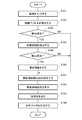
- the edge extraction unit 201 of the movement vector detection unit 121 pays attention to the top pixel of the current frame stored in the encoding target frame storage unit 111 (step S201 in FIG. 5), and determines whether the pixel under attention is an edge point. Determination is made (step S202). If it is not an edge point, attention is shifted to the next pixel in the order of the raster scan direction (step S206), and it is determined whether the pixel being noticed is an edge point (step S202).
- step S202 If the pixel of interest is an edge point (YES in step S202), the set of the coordinate value and pixel value of the pixel of interest is temporarily stored in the work area 113 as edge point information (step S203). Next, the distance to the immediately preceding edge point stored in the work area 113 is obtained, and the lower 11 bits of the distance are calculated as a hash value (step S204), corresponding to the current frame stored in the work area 113.
- the hash table to be updated is updated (step S205). For example, as illustrated in FIG.
- an example of a hash table corresponding to the current frame has an entry corresponding to each hash value from 0 to 2047 in a one-to-one correspondence, and each entry has an appearance frequency, a final appearance coordinate, and a pixel value. be registered.
- the initial value of the appearance frequency is 0, and the initial values of the final appearance coordinates and the pixel value are NULL.
- the edge extraction unit 201 increments the appearance frequency of the entry having the calculated hash value by 1, and sets the detected edge point coordinate value and pixel value to the final appearance coordinate and pixel value. Record in the column.
- the appearance frequency in the entry of the hash value 4 in FIG. 7 is incremented by 1, and the coordinate value and the pixel value of the pixel P (5, 1) are recorded in the same entry. Is done.
- the edge extraction unit 201 repeatedly executes the above processing up to the last pixel of the current frame.
- the feature point extraction unit 202 refers to the hash table corresponding to the current frame and sets the coordinate value and the pixel value to the entry whose appearance frequency is 1. Are extracted as feature points (step S208). For example, when the hash table corresponding to the current frame at the time when the processing of the edge extraction unit 201 is completed is the one shown in FIG. 7, the pixel P (5, 1) is extracted as one feature point.
- the feature point pair extraction unit 203 refers to the hash table corresponding to the current frame and the hash table corresponding to the previous frame, and extracts all pairs of feature points having the same hash value (step S209).
- the hash table corresponding to the previous frame is created by the edge extraction unit 201 when the previous frame is processed as the current frame, and is stored in the work area 113.
- the hash value is the same as the pixel P (5,1) extracted as the feature point from the current frame shown in FIG. Since the pixel P (5, 8) exists in the previous frame, the pair of the pixel P (5, 8) in the previous frame and the pixel P (5, 1) in the current frame is extracted as one feature point pair. .
- the feature point pair extraction unit 203 has a high possibility of correspondence among pairs of feature points extracted in step S209, in which the difference between the R, G, and B color components is less than or equal to a preset threshold value. Therefore, the remaining feature point pairs are excluded (step S210).
- the feature point pair extraction unit 203 records the remaining feature point pair information in the work area 113.
- the movement vector candidate generation unit 205 of the movement vector calculation unit 204 reads feature point pair information from the work area 113, and generates a coordinate value difference as a movement vector candidate for each pair (step S211). For example, in the case of the above-described pair of feature points P (5, 8) and P (5, 1), (0, -7) is generated as a motion vector candidate. Since still vectors are ignored, they are excluded from candidates when the difference is (0, 0).
- the movement vector candidate generation unit 205 records movement vector candidate information in the work area 113.
- the movement vector selection unit 206 reads out information on the movement vector candidates from the work area 113, counts the total number of the same movement vector candidates, obtains the appearance frequency of each movement vector candidate, and determines the most frequent movement vector candidate. It selects as an estimated value of the main movement vector (step S212).
- the movement vector selection unit 206 records the movement vector detection result in the work area 113 (step S213).
- FIG. 10 shows the relationship between an image obtained by plotting pairs of feature points included in the detection result in the previous frame and the current frame, and the estimated movement vector.
- the motion vector estimated from the most frequent motion vector candidate is the main motion vector among one or more motion vectors existing in the current frame.
- the movement vector detection unit 121 of the present embodiment it is possible to detect main movement vectors at high speed and with high accuracy from the video signal of the computer screen.
- the reason is that, firstly, it is not necessary to search various vectors in each pixel block, and the movement vector is obtained by extracting and comparing edge points and feature points, and secondly, the raster scan order in the frame. Because of this processing, the locality of memory access is high, and thirdly, since a comparison is made not on a block basis but on the entire screen, a movement vector in a relatively large object unit such as a window can be detected as a main movement vector. Fourthly, since the vector is detected based on the edge point, it is not necessary to accurately match the pixel value between the movement source and the movement destination, and it is possible to deal with a noisy video signal captured in analog. .
- the movement vector detection unit 121 of the present embodiment (1) does not detect a plurality of vectors at the same time, (2) does not detect a movement vector of an object accompanied by a sub-pixel unit or deformation, and (3) an object with few edges. There is a restriction that no motion vector is detected. However, (1) and (2) are unlikely to occur on a computer screen, and even if a region such as (3) is encoded as an image as it is, the amount of code becomes small, so that there is no big problem.
- the first example of the moving area detecting unit 122 includes an initial candidate determining unit 301 and a moving area determining unit 302. Each has the following functions in general.
- the initial candidate determination unit 301 has a function of determining an initial candidate for a moving area.
- the moving region determining unit 302 moves the motion compensation unit 123 from among the initial moving region candidate determined by the initial candidate determining unit 301 and one or more other moving region candidates whose sizes are changed. It has a function of determining a moving area to be used for compensation.
- the initial candidate determining unit 301 of the moving region detecting unit 122 determines the moving region of the initial candidate (step S301 in FIG. 12).
- a method for determining an initial candidate there is a method in which a rectangle circumscribing a feature point group that is a source of calculation of the motion vector candidate used by the motion vector detection unit 121 for estimating the motion vector is used as an initial candidate for the motion region. .
- the movement vector selection unit 206 of the movement vector detection unit 121 generates a detection result as illustrated in FIG. 9, the movement region detection unit 122 extracts the feature points described in the detection result from the work area 113. Read every previous frame and current frame.
- the movement area detection unit 122 sets a rectangle circumscribing the feature point group as the movement area before movement as shown in the previous frame of FIG. Then, the movement area detection unit 122 detects a rectangle circumscribing the feature point group as the movement area after movement as shown in the current frame in FIG. Information on the detected moving area of the initial candidate is temporarily recorded in the work area 113.
- a rectangle circumscribing any three or more feature points in the feature point group included in the motion vector candidate used by the motion vector detection unit 121 for estimating the motion vector is used.
- the moving region determining unit 302 of the moving region detecting unit 122 determines a moving region to be used for motion compensation from among the initial candidates and other candidates (step S302).
- a configuration example of the movement area determination unit 302 will be described in detail.
- Example 1 of the movement area determination unit 302 An example of processing performed by the movement region determination unit 302 in Example 1 is illustrated in FIGS. 14A and 14B.
- the moving region determination unit 302 actually performs motion compensation based on the determined moving region and moving vector of the initial candidate, compares the pixel values, and confirms whether or not they are correctly translated. Specifically, whether the code amount reduced by motion compensation or the code amount increased by motion compensation increases depends on whether the moving region is suitable as a moving region used for motion compensation or not. Using the merit values and demerit values shown as evaluation scales, estimation is performed by the following method (steps S311 and S312).
- the merit value is an evaluation scale indicating the degree to which the moving area is suitable as a moving area used for motion compensation
- the demerit value is an evaluation scale indicating the degree to which the moving area is not suitable as a moving area used for motion compensation.
- the initial value is 0.
- the reason for adding the condition that there is a luminance gradient equal to or greater than the threshold value between adjacent pixels is that a portion including a point having a luminance gradient generally increases the amount of code in encoding by difference. .
- the above-mentioned processes (a) and (b) are performed on the entire moving area of the initial candidate, and if the merit value is larger than the demerit value, it is adopted as the moving area, otherwise it is rejected.
- the process of adding the merit value and the demerit value according to the comparison result of the pixel value and comparing the final merit value and the demerit value is the addition using only one of the merit value and the demerit value. It is equivalent to using subtraction properly. Specifically, first, every time a pixel in which the difference between the pixel value after motion compensation and the true pixel value is equal to or greater than a predetermined threshold is detected, the merit value is subtracted by the predetermined value (or the demerit value is decreased by the predetermined value). to add. Next, every time a pixel is detected that has a difference between the pixel value after motion compensation and the true pixel value that is smaller than a predetermined threshold and has a luminance gradient greater than or equal to the threshold between adjacent pixels. A process of adding a value by a predetermined value (or subtracting a demerit value by a predetermined value) is performed. Thereby, the positive or negative value of the final merit value (or demerit value) may be determined.
- Step S312 When the initial candidate for the moving area is rejected (NO in step S312), the detection of the moving area is no longer performed in this example and the detection result indicating that the detection of the moving area has failed is recorded in the work area 113 ( Step S323), the processing of FIG. 14A and FIG. 14B ends.
- step S312 when the initial candidate for the moving area is adopted (YES in step S312), it is checked whether the area can be further expanded vertically and horizontally by the following procedure.
- step S313 For each line of the moving area, when the area is expanded to the right, the number of continuous pixels in which the “pixel value after motion compensation” and the “true pixel value” match (the difference is equal to or less than the threshold) is checked.
- the right end is determined by setting the minimum value of the number of continuous pixels as the maximum enlargement width to the right (step S313). For example, as shown in FIG. 15, when the right end of the initial candidate is expanded to the right, the first line and the third line are continuously 3 pixels, and all the remaining lines are 2 pixels consecutively. If the “pixel value” and the “true pixel value” match, the maximum enlargement width to the right is two pixels, which is the minimum value of the number of continuous pixels.
- step S315 to S318 The area is further expanded one line at a time with respect to the moving area after the processing of (I) and (II) described above (steps S315 to S318).
- the merit value and demerit value when one line is enlarged are calculated in the same manner as in the above (a) and (b) (steps S315 and S316), and if the merit value is larger than the demerit value ( YES in step S317), the process returns to step S315, and the same processing is performed for the next line. If the merit value is not larger than the demerit value, the upper end before the enlargement of one line is determined as the upper end of the moving area (step S318).
- the moving area determining unit 302 records the detection result including the coordinate information of the enlarged moving area in the work area 113 (step S323), and finishes the processes of FIGS. 14A and 14B.
- the reason for adopting different methods for the left and right expansion of the moving area and the vertical expansion is that the memory access to a plurality of pixels on the same line can be performed at a high speed, but the pixels on different lines can be accessed. This is because it takes time to access the memory. In other words, if the horizontal expansion is performed sequentially one column at a time in the same manner as the top and bottom, memory access over all lines of the moving area is required even if only one column is expanded. However, under such a situation where the memory access time does not become a problem, the movement region may be expanded to the left and right by the same method as the vertical expansion. On the contrary, the movement region may be enlarged up and down by a simple method used for right and left enlargement.
- the moving region determination unit 302 of Example 1 since the validity of the initial candidate determined by the initial candidate determination unit 301 can be quantitatively determined, motion compensation using an inappropriate moving region is prevented. can do. In addition, when the initial candidate is valid, it is possible to search for a moving region having a larger size and having a large code amount reduction effect.
- Example 2 of moving area determination unit 302 A processing example of the movement area determination unit 302 of Example 2 is shown in FIGS. 16A and 16B.
- the difference between Example 2 and Example 1 is as follows. In Example 1, only a moving region having a size larger than the initial candidate was searched. On the other hand, in Example 2, considering the possibility that the moving area is excessively detected as an area larger than the true moving area, first, the possibility of area reduction is determined for each side. Sides that have not been detected are enlarged as in Example 1.
- the moving area determination unit 302 determines the validity of the moving area of the initial candidate by the same method as in Example 1 (Steps S331 and S332).
- the initial candidate for the moving area is rejected (NO in step S332)
- the moving area is no longer detected in this example as in Example 1, and the detection result indicating that the moving area has failed to be detected is displayed in the work area 113. (Step S357), and the processing of FIGS. 16A and 16B is terminated.
- step S332 when the initial candidate for the moving area is adopted (YES in step S332), it is checked whether the area can be further reduced from the top, bottom, left, and right, and whether it can be expanded from top to bottom, left, and right by the following procedure.
- the moving area determination unit 302 calculates the maximum reduction width from the right of the moving area of the initial candidate (step S333). Specifically, for each line of the moving region, the number of consecutive pixels in which the “pixel value after motion compensation” does not match the “true pixel value” when the region is narrowed from the right (the difference is greater than or equal to the threshold value). And the right end is determined with the minimum value of the number of continuous pixels as the maximum reduction width from the right. For example, as shown in FIG. 17, when the right edge of the initial candidate is narrowed from the right, the first line, the fourth line, and the fifth line are three consecutive pixels, and the remaining lines are two consecutive pixels. If the “pixel value after motion compensation” and the “true pixel value” do not match, the maximum reduction width from the right is set to two pixels, which is the minimum value of the number of continuous pixels.
- the moving area determination unit 302 determines whether or not the maximum reduction width is 0 (step S334). If the maximum reduction width is not 0, for example, as shown in FIG. 17, the maximum reduction width is determined from the right end of the initial candidate. The portion narrowed by the distance is determined as the right end of the movement area (step S335). If the maximum reduction width is 0, the maximum enlargement width to the right of the moving area is calculated in the same manner as in Example 1, and the right end is determined (step S336).
- the moving area determination unit 302 calculates the maximum reduction width from the left end of the initial area in the same manner as the right end (step S337). If the maximum reduction width is not 0, the left end is determined from the maximum reduction width (step S338). 339). If the maximum reduction width is 0, the maximum extension width from the left end is calculated in the same manner as in Example 1, and the left end is determined (step S340).
- the moving area determination unit 302 reduces the moving area by one line from the top, and calculates the merit value and the demerit value when the line is reduced by the same method as the above-described (a) and (b) (steps). S341, S342). If the merit value is smaller than the demerit value (YES in step S343), the same reduction process is repeated for the next line (steps S344 to S346). If it is detected that the merit value is not smaller than the demerit value, the upper end before the reduction of one line is determined as the upper end of the movement region (step S347). On the other hand, if it is determined in step S343 that the merit value is not smaller than the demerit value, the maximum extension width above the moving region is calculated by the same method as in Example 1 and the upper end is determined (step S348).
- the movement area determination unit 302 performs the same process from the bottom of the movement area as from the top (steps S349 to S356).
- the moving area determination unit 302 records the detection result including the coordinate information of the moving area in which the upper, lower, left and right ends are determined in the work area 113 (step S357), and finishes the processes of FIGS. 16A and 16B.
- the reason why different methods are adopted for the reduction from the left and right of the moving region and the reduction from the top and bottom is that memory access to a plurality of pixels on the same line can be performed at a high speed, but to the pixels on different lines. This is because it takes time to access the memory. In other words, if the horizontal reduction is performed one column at a time in the same manner as the top and bottom, memory access over all the lines of the moving area is required even by reducing one column. However, under such a situation where the memory access time does not become a problem, the movement area may be reduced from the left and right by the same method as the reduction from the top and bottom. Conversely, reduction from the top and bottom of the moving area may be performed by a simple method used for reduction from the left and right.
- the moving region determination unit 302 of Example 2 since the validity of the initial candidate determined by the initial candidate determination unit 301 can be quantitatively determined, motion compensation using an inappropriate moving region is prevented. can do.
- the initial candidate when the initial candidate is valid, it tries to reduce from the top, bottom, left, and right, so if the initial candidate's moving area is excessively detected as a larger area than the true moving area, the excess detection amount should be reduced. Is possible.
- the side where there is no possibility of excessive detection can be expanded to a larger moving region with a large code amount reduction effect.
- Example 3 of moving area determination unit 302 A processing example of the movement area determination unit 302 of Example 3 is shown in FIG. The difference between Example 3 and Example 2 is that in Example 3, when the merit value calculated for the initial candidate was lower than the demerit value, detection of the moving region was no longer given, whereas in Example 3, the move In consideration of the possibility that the area is detected to be extremely larger than the true moving area, the possibility of reducing the area is determined for each side.
- the moving area determination unit 302 determines the validity of the moving area of the initial candidate by the same method as in Example 2 (Steps S361 and S362). Processing step S363 when the initial candidate for the moving area is not rejected (YES in step S362) is the same as steps S333 to S356 in example 2.
- step S362 if the initial candidate for the moving area is rejected (NO in step S362), it is checked whether the area can be further reduced from the top, bottom, left, and right by the following procedure.
- the moving area determination unit 302 calculates the maximum reduction width from the right of the moving area of the initial candidate by the same method as in Example 2 (step S364).
- the moving area determination unit 302 determines whether or not the maximum reduction width is equal to the horizontal width of the moving area (step S365). If the maximum reduction width is equal to the horizontal width of the moving area, it is determined that the detection of the moving area has failed. Then, a detection result to that effect is generated (YES in step S365, step S372), and the process in FIG. If the maximum reduction width is not equal to the horizontal width of the moving area, a portion narrowed by the maximum reduction width from the right end of the initial candidate is determined as the right end of the moving area (step S366).
- the moving area determination unit 302 calculates the maximum reduction width from the left end of the initial area in the same manner as the right end, and determines the left end (step S367).
- the movement area determination unit 302 calculates the maximum reduction width from above the movement area by the same method as in Example 2 (step S368). If the maximum reduction width is equal to the vertical width of the moving area, the detection result indicating that the moving area has failed is generated (YES in step S369, step S372), and the process in FIG. 18 is terminated. If the maximum reduction width is not equal to the vertical width of the movement area, the upper end of the movement area is determined from the maximum reduction width (step S370).
- the movement area determination unit 302 calculates the maximum reduction width from the bottom of the movement area in the same manner as above, and determines the lower end (step S371).
- the moving area determination unit 302 records the detection result including the coordinate information of the moving area in which the upper, lower, left, and right ends are determined in the work area 113 (step S372), and ends the process of FIG.
- the moving region determination unit 302 of Example 3 since the validity of the initial candidate determined by the initial candidate determination unit 301 can be quantitatively determined, motion compensation using an inappropriate moving region is prevented. can do. Even if the initial candidate is rejected, in order to search for the possibility of reduction, even if the moving area of the initial candidate is detected to be excessively larger than the true moving area, the moving area is set as much as possible. It becomes possible to detect. Further, as in Example 2, when the initial candidate is valid, first, the reduction from the top, bottom, left, and right is attempted. Therefore, if the initial candidate moving area is excessively detected as an area larger than the true moving area, excessive It is possible to reduce the amount of detection. Similarly, the side where there is no possibility of excessive detection can be expanded to a larger moving region that has a large code amount reduction effect.
- Example 4 of moving area determination unit 302 An example of processing performed by the movement region determination unit 302 in Example 4 is shown in FIGS. 19A and 19B.
- the difference between Example 4 and Example 2 is that in Example 2, the validity of the initial candidate is determined, and when it is determined to be valid, the moving region is reduced and expanded, whereas in Example 4, the initial candidate is It is in the point of omitting the determination of the validity of and trying to reduce or expand the initial candidate.
- the moving area determination unit 302 calculates the maximum reduction width from the right of the moving area of the initial candidate by the same method as in Example 2 (step S381). Next, the movement area determination unit 302 determines whether or not the maximum reduction width is equal to the horizontal width of the movement area (step S382). If the maximum reduction width is equal to the horizontal width of the movement area (NO in step S382), the movement area is determined. Is detected (step S399), the processing of FIGS. 19A and 19B is terminated.
- the movement area determination unit 302 determines whether the maximum reduction width is 0 (step S383). Then, the portion narrowed by the maximum reduction width is determined as the right end of the moving region (step S384). If the maximum reduction width is 0, the moving region determination unit 302 calculates the maximum enlargement width to the right by the same method as in Example 2 and determines the right end (step S385).
- the moving area determination unit 302 calculates the maximum reduction width from the left of the moving area of the initial candidate by the same method as in Example 2 (step S386), and if the maximum reduction width is not 0 (NO in step S387). Then, a portion narrowed by the maximum reduction width from the left end of the initial candidate is determined as the left end of the moving region (step S388). If the maximum reduction width is 0, the moving area determination unit 302 calculates the maximum enlargement width to the left by the same method as in Example 2 and determines the left end (step S389).
- the movement area determination unit 302 calculates the maximum reduction width from above the movement area by the same method as in Example 2 (step S390). If the maximum reduction width is equal to the vertical width of the moving area, it is determined that the detection of the moving area has failed, and a detection result to that effect is generated (YES in step S391, S399), and the processes in FIGS. 19A and 19B are terminated. To do. If the maximum reduction width is not equal to the vertical width of the moving area, it is determined whether or not the maximum reduction width is 0 (NO in step S391, step S392). If not, the maximum reduction width is narrowed from the upper end of the initial candidate by the maximum reduction width. The location is determined as the upper end of the movement area (step S393). If the maximum reduction width is 0, the moving area determination unit 302 calculates the maximum enlargement width upward using the same method as in Example 2 and determines the upper end (step S394).
- the movement area determination unit 302 calculates the maximum reduction width from the bottom of the movement area by the same method as in Example 2 (step S395). If it is not 0, a position narrowed by the maximum reduction width from the lower end of the initial candidate Is determined as the lower end of the movement area (NO in step S396, S397). If the maximum reduction width is 0, the moving area determination unit 302 calculates the maximum downward expansion width by the same method as in Example 2 and determines the lower end (step S398).
- the movement area determination unit 302 records the detection result including the coordinate information of the movement area where the end portions of the upper, lower, left, and right are determined in the work area 113 (step S399), and ends the processes of FIGS. 19A and 19B.
- the processing amount can be reduced. Further, since the reduction from the top, bottom, left, and right is first attempted, it is possible to reduce the amount of excess detection when the initial candidate movement area is excessively detected as a larger area than the true movement area. Similarly, the side where there is no possibility of excessive detection can be expanded to a larger moving region that has a large code amount reduction effect. However, since the validity of the moving area of the initial candidate is not determined, there is a possibility that an area where the donut-shaped hole part is completely different before and after the movement is detected as the moving area, for example.
- Update area detection area setting unit 124 includes a movement area presence / absence determination unit 401, a movement direction determination unit 402, and a division unit 403. Each has the following functions in general.
- the moving area presence / absence determining unit 401 has a function of determining whether or not a moving area is detected by the moving area detecting unit 122.
- the movement direction determination unit 402 has a function of determining the movement direction of the movement area detected by the movement area detection unit 122.
- the division unit 403 has a function of determining the necessity of screen division and setting an update region detection area by screen division according to the determination results of the movement region presence / absence determination unit 401 and the movement direction determination unit 402.
- the movement area presence / absence determination unit 401 of the update area detection area setting unit 124 reads out and analyzes the detection result of the movement area detection unit 122 from the work area 113 to determine whether or not a movement area has been detected, and determines the determination result. Notification is made to the moving direction determination unit 402 and the dividing unit 403 (step S501 in FIG. 21).
- the moving direction determination unit 402 determines the moving direction (step S502). Specifically, the movement direction determination unit 402 first receives a notification from the movement region presence determination unit 401 that a movement region has been detected. Next, the movement direction determination unit 402 compares the movement area coordinates before movement included in the detection result of the movement area detection unit 122 read from the work area 113 with the coordinates of the movement area after movement. Is a direction including a component from the top to the bottom of the screen (hereinafter referred to as “downward direction”) or a direction including a component from the bottom of the screen to the top (hereinafter referred to as “upward direction”). Then, the moving direction determination unit 402 notifies the division unit 403 of the determination result.
- the determination result includes the coordinates of the upper end of the movement area after movement in the case of the downward direction, and the coordinates of the lower end of the movement area after the movement in the case of the upward direction.
- a method of handling in the left-right direction that is neither downward nor upward for example, it can be considered to include either the downward or upward direction.
- the dividing unit 403 When the dividing unit 403 receives notification from the moving region presence / absence determining unit 401 that the moving region has not been detected, the dividing unit 403 sets the entire screen as one update region detecting region (step S503).
- the screen is divided in accordance with the notification from the moving direction determining unit 402 (steps S504 to S506). Specifically, if the movement direction is downward, the screen is divided into two at the upper end of the moved area after movement, and each divided area is set as one update area detection area. If the moving direction is upward, the screen is divided into two at the lower end of the moving area after movement, and each divided area is set as one update area detection area. Thereafter, the update area detection unit 125 detects the update area for each update area detection area.
- the upper left of FIG. 22 shows that the movement area R11 has moved to the movement area R12 on the screen R1, that is, the movement area has moved downward.
- the upper right of FIG. 22 shows the case where the entire screen R2 is set as the update region detection area. At this time, the entire area corresponding to the movement area R21 before movement is detected as the update area. In addition, the movement region R20 after the movement is not detected.
- the screen R3 is divided into two by the dividing line L221 at the upper end of the moving area R30 after movement, and the update areas R31 and R32 are detected in each update area detection area. As a result, the total area of the update region can be minimized and the amount of codes can be reduced.
- the moving region presence / absence determining unit 401 of the update region detecting region setting unit 124 determines whether or not a moving region has been detected, as in the first processing example, and notifies the moving direction determining unit 402 and the dividing unit 403 of the determination result. (Step S511 in FIG. 23).
- the movement direction determination unit 402 determines whether the movement direction is downward or upward. The determination is made and the determination result is notified to the dividing unit 403 (step S512).
- the determination result includes the coordinates of the upper and lower ends of the movement area after the movement in both the downward direction and the upward direction.
- the dividing unit 403 When the dividing unit 403 receives a notification from the moving region presence / absence determining unit 401 that the moving region has not been detected, the dividing unit 403 sets the entire screen as one update region detecting region as in the first processing example (step S513). ).
- the screen is divided in accordance with the notification from the moving direction determining unit 402 (steps S514 to S516). Specifically, the screen is divided into three at the upper and lower ends of the moving area after movement in both the downward direction and the upward direction, and each divided area is set as one update area detection area. Thereafter, the update area detection unit 125 detects the update area for each update area detection area.
- the upper left and upper right in FIG. 24 are the same as the upper left and upper right in FIG.
- the screen R3 is divided into three by dividing lines L241 and L242 at the upper and lower ends of the moving area R30 after the movement, and the update areas R31 and R32 in the respective update area detection areas. Therefore, the total area of the update region can be minimized, and the amount of codes can be reduced.
- the upper left of FIG. 25 shows a case where the moving area R13 detected on the screen R1 is smaller than the actual moving area R12.
- the upper right of FIG. 25 shows a case where the first processing example of FIG. 21 is applied and the screen R2 is divided into two by the dividing line L251 only at the upper end after the movement.
- the update areas R22 and R23 that are unnecessarily large are detected, including the movement area R20a detected as shown in the upper right of FIG.
- the screen R3 is divided into three by the dividing lines L252 and L253 at the upper and lower ends of the moving area R30a after the movement, and the update areas R331 and R332 in the respective update area detection areas. , R333 and R334 are detected, the total area of the update region can be reduced, and the amount of code can be reduced accordingly.
- the moving region presence / absence determining unit 401 of the update region detecting region setting unit 124 determines whether or not a moving region has been detected as in the second processing example, and notifies the moving direction determining unit 402 and the dividing unit 403 of the determination result. (Step S521 in FIG. 26).
- the movement direction determination unit 402 determines whether the movement direction is downward or upward. The determination is made and the determination result is notified to the dividing unit 403 (step S522).
- the judgment result includes the coordinates of the upper and lower ends of the moving area after moving and the lower end of the moving area before moving if the moving direction is downward. If the moving direction is upward, The coordinates of the upper and lower ends of the movement area after movement and the upper end of the movement area before movement are included.
- the dividing unit 403 When the dividing unit 403 receives a notification from the moving region presence / absence determining unit 401 that the moving region has not been detected, the dividing unit 403 sets the entire screen as one update region detecting region as in the second processing example (step S523). ).
- the screen is divided in accordance with the notification from the moving direction determining unit 402 (steps S524 to S526). Specifically, when the moving direction is downward, the screen is divided into four at the upper and lower ends of the moving area after moving and the lower end of the moving area before moving, and each divided area is set as one update area detection area. .
- the screen When the moving direction is upward, the screen is divided into four at the upper and lower ends of the moving area after moving and the upper end of the moving area before moving, and each divided area is set as one update area detecting area. Thereafter, the update area detection unit 125 detects the update area for each update area detection area.
- the upper left and upper right in FIG. 27 are the same as the upper left and upper right in FIG.
- the screen R3 is divided into four by dividing lines L271, L272, and L273 at the upper and lower ends of the moving region R30 after movement and the lower end of the moving region before movement. Since the update areas R31 and R32 are detected in the update area detection area, the total area of the update areas can be minimized and the code amount can be reduced.
- the upper left of FIG. 28 is the same as the upper left of FIG.
- the upper right of FIG. 28 shows a case where the first processing example of FIG. 21 is applied and the screen R2 is divided into two by the dividing line L281 only at the upper end after movement.
- the update areas R22 and R23 that are unnecessarily large are detected, including the movement area R20a detected as shown in the upper right of FIG.
- the screen R3 is divided into four by dividing lines L281, L282, and L283 at the upper and lower ends of the moving area R30b after movement and the lower end of the moving area before movement. Since the update area is detected in the update area detection area, the total area of the update area can be reduced, and the code amount can be reduced accordingly.
- the upper left of FIG. 29 shows a case where the movement area R14 detected on the screen R1 is larger than the actual movement area R12.
- the upper right of FIG. 29 shows a case where the first processing example of FIG. 21 is applied and the screen R2 is divided into two by the dividing line L291 only at the upper end after the movement.
- the update areas R24 and R25 that are unnecessarily large are detected, including the movement area R20b detected as shown in the upper right of FIG.
- the lower right part of FIG. 29 shows a case where the second processing example of FIG. 23 is applied and the screen R3 is divided into three by dividing lines L292 and L293 only at the upper and lower ends of the movement area R30c after movement.
- the update areas R351 and R352 are somewhat redundant, including the detected movement area R30c as shown in the lower right of FIG.
- the screen R4 is divided into four by dividing lines L294, L295, and L296 at the upper and lower ends of the moving area R40 after movement and the lower end of the moving area before movement. Since the update areas R41, R42, and R43 are detected in the area detection area, the total area of the update areas can be reduced compared to the second processing example, and the code amount can be reduced correspondingly. However, if the area of the excessively detected region is not so large, the second processing example has an advantage that the number of update regions is reduced.
- the second embodiment of the update region detection region setting unit 124 includes a moving region presence / absence determining unit 411, a moving region overlap determining unit 412, a moving direction determining unit 413, and a dividing unit 414. Is done. Each has the following functions in general.
- the movement region presence / absence determination unit 411 and the movement direction determination unit 413 have the same functions as the movement region presence / absence determination unit 401 and the movement direction determination unit 402 in the first embodiment of the update region detection area setting unit 124.
- the movement area overlap determination unit 412 has a function of determining whether or not there is a possibility of overlapping of the movement areas before and after the movement detected by the movement area detection unit 122.
- the dividing unit 414 has a function of determining the necessity of screen division and setting an update region detection area by screen division according to the determination results of the moving region presence / absence determining unit 411, the moving region overlap determining unit 412 and the moving direction determining unit 413. .
- the moving region presence / absence determination unit 411 of the update region detection region setting unit 124 determines whether or not a moving region has been detected in the same manner as the moving region presence / absence determination unit 401 of the first embodiment, and determines the determination result as a moving region overlap determination unit. 412 and the dividing unit 414 (step S531 in FIG. 31).
- the movement area overlap determination unit 412 determines whether or not the movement areas before and after the movement overlap (step S532). Specifically, the moving region overlap determination unit 412 first receives a notification from the moving region presence determination unit 401 that a moving region has been detected. Next, the movement area overlap determination unit 412 reads the coordinates of the movement area before the movement and the coordinates of the movement area after the movement included in the detection result of the movement area detection unit 122 from the work area 113. Then, the movement area overlap determination unit 412 includes at least a part of an area obtained by enlarging the movement area before movement vertically and horizontally by a predetermined width ⁇ and an area obtained by enlarging the movement area after movement vertically and horizontally by a predetermined width ⁇ .
- the moving region overlap determination unit 412 notifies the moving direction determination unit 413 and the dividing unit 414 of the determination result that there is overlapping of moving regions when they overlap, and the determination result that there is no overlapping of moving regions when they do not overlap.
- the predetermined width ⁇ is set in advance in accordance with the degree of insufficient detection of the moving area.
- the moving direction determination unit 413 determines the moving direction (step S533). Specifically, the movement direction determination unit 413 first receives from the movement region overlap determination unit 412 a notification that there is no overlap of movement regions. Next, the movement direction determination unit 413 compares the coordinates of the movement area before the movement included in the detection result of the movement area detection unit 122 read from the work area 113 with the coordinates of the movement area after the movement. Then, it is determined whether the moving direction is the downward direction or the upward direction. Then, the moving direction determination unit 413 notifies the determination unit 414 of the determination result (step S533).
- the determination result includes coordinates for dividing the screen in addition to the movement direction, as in the movement direction determination unit 402 in the first embodiment.
- the dividing unit 414 When the dividing unit 414 receives a notification that the moving region is not detected from the moving region presence / absence determining unit 411 and when the moving unit overlap determining unit 412 receives a notification indicating no overlapping of moving regions, the dividing unit 414 displays the entire screen.
- One update area detection area is set (step S534).
- the notification from the moving direction determining unit 413 is followed.
- the screen is divided and the update area detection area is set (steps S535 to S537). ). Thereafter, the update area detection unit 125 detects the update area for each update area detection area.
- the screen is not divided when there is no possibility that the movement areas before and after the movement overlap, so that an increase in the number of divisions of the update area is suppressed. Can do.
- the third embodiment of the update area detection area setting unit 124 includes a moving area presence / absence determination unit 501 and a division unit 502. Each has the following functions in general.
- the moving area presence / absence determining unit 501 has a function of determining whether or not a moving area is detected by the moving area detecting unit 122.
- the division unit 502 has a function of determining the necessity of screen division and setting an update region detection area by screen division according to the determination result of the moving region presence / absence determination unit 501.
- the moving region presence / absence determining unit 501 of the update region detecting region setting unit 124 reads out and analyzes the detection result of the moving region detecting unit 122 from the work area 113 to determine whether or not a moving region has been detected, and determines the determination result.
- the division unit 502 is notified (step S601 in FIG. 33).
- the dividing unit 502 When the dividing unit 502 receives a notification that the moving area has not been detected from the moving area presence / absence determining unit 501, the dividing unit 502 sets the entire screen as one update area detecting area (step S602). In addition, when the notification that the moving area is detected is received from the moving area presence / absence determining unit 401, the coordinates of the moving area after the movement included in the detection result of the moving area detecting unit 122 are read from the work area 113, and after the movement The screen is divided into three at the upper and lower ends of the moving area (step S603), and each divided area is set as one update area detection area (step S604). Thereafter, the update area detection unit 125 detects the update area for each update area detection area.
- the screen R3 is divided into three by dividing lines L341 and L342 at the upper and lower ends of the moving area R30 after the movement, and the update areas R31 and R32 in the respective update area detection areas. Therefore, the total area of the update region can be minimized, and the amount of codes can be reduced.
- the upper left of FIG. 35 is the same as the upper left of FIG.
- the upper right of FIG. 35 shows a case where the entire screen R2 is set as the update region detection area.
- the moving region R26 including the moving region R20c detected as shown in the upper right of FIG. 35 and including the moving region before and after the movement is detected.
- the screen R3 is divided into three by dividing lines L351 and L352 at the upper and lower ends of the moving area R30a after the movement, and the update areas R331 and R332 in the respective update area detection areas. , R333 and R334 are detected, the total area of the update region can be reduced, and the amount of code can be reduced accordingly.
- the moving region presence / absence determination unit 501 of the update region detection region setting unit 124 determines whether a moving region has been detected as in the first processing example, and notifies the division unit 502 of the determination result (step S611 in FIG. 36). ).
- the division unit 502 When the division unit 502 receives a notification from the movement region presence / absence determination unit 501 that the movement region has not been detected, the division unit 502 sets the entire screen as one update region detection region as in the first processing example (step S612). ). Further, when the notification that the moving area has been detected is received from the moving area presence / absence determining unit 501, the coordinates of the moving area before and after the movement included in the detection result of the moving area detecting unit 122 are read from the work area 113, and before the movement. The upper and lower ends of the moving area and the upper and lower ends of the moved moving area are divided into five (step S613), and each divided area is set as one update area detecting area (step S614). Thereafter, the update area detection unit 125 detects the update area for each update area detection area.
- the upper left and upper right of FIG. 37 are the same as the upper left and upper right of FIG.
- the screen R3 is divided into five by dividing lines L371, L372, L373 and L374 at the upper and lower ends of the moving area R30 before and after the movement, and updated in each update area detection area. Since the areas R31 and R32 are detected, the total area of the update area can be minimized and the code amount can be reduced.
- the upper left and upper right of FIG. 38 are the same as the upper left and upper right of FIG.
- the screen R3 is divided into five by dividing lines L381, L382, L383, and L384 at the upper and lower ends of the moving area R30d before and after the movement, and updated in each update area detection area. Since the areas R361, R362, R363, R364, R365, R366, and R367 are detected, the total area of the update area can be reduced, and the code amount can be reduced accordingly.
- the upper left of FIG. 39 is the same as the upper left of FIG.
- the upper right of FIG. 39 is the same as the upper right of FIG. 39 shows a case where the first processing example is applied and the screen R3 is divided into three by dividing lines L391 and L392 at the upper and lower ends of the moving area R30c after movement. In this case, redundant update areas R351 and R352 are detected including the movement area R30c detected as shown in the lower right of FIG.
- the screen R4 is divided into five by dividing lines L393, L394, L395, and L396 at the upper and lower ends of the moving region R40 before and after the movement, and the update region is detected in each update region detection region. Since R41, R42, and R43 are detected, the total area of the update region can be reduced, and the amount of code can be reduced accordingly.
- the fourth embodiment of the update area detection area setting unit 124 includes a movement area presence / absence determination unit 511, a movement area overlap determination unit 512, and a division unit 513. Each has the following functions in general.
- the moving area presence / absence determination unit 511 has the same function as the moving area presence / absence determination unit 501 in the third embodiment of the update area detection area setting unit 124.
- the movement area overlap determination unit 512 has a function of determining whether or not there is a possibility of overlapping of the movement areas before and after the movement detected by the movement area detection unit 122.
- the dividing unit 513 has a function of determining the necessity of screen division and setting an update region detection region by screen division according to the determination results of the moving region presence / absence determining unit 511 and the moving region overlap determining unit 512.
- the moving region presence / absence determination unit 511 of the update region detection region setting unit 124 determines whether or not a moving region has been detected in the same manner as the moving region presence / absence determination unit 501 of the third embodiment, and determines the determination result as a moving region overlap determination unit. 512 and the dividing unit 513 (step S621 in FIG. 41).
- the movement area overlap determination unit 512 determines whether or not the movement areas before and after the movement overlap (step S622). Specifically, the movement region overlap determination unit 512 first receives a notification that a movement region has been detected from the movement region presence / absence determination unit 511. Next, the movement area overlap determination unit 512 reads out the coordinates of the movement area before and after movement included in the detection result of the movement area detection unit 122 from the work area 113.
- the movement area overlap determination unit 512 includes at least a part of an area obtained by enlarging the movement area before movement vertically and horizontally by a predetermined width ⁇ and an area obtained by enlarging the movement area after movement vertically and horizontally by a predetermined width ⁇ . Check if they overlap.
- the moving region overlap determination unit 512 notifies the dividing unit 513 of the determination result that there is overlap of moving regions when they overlap, and the determination result that there is no overlap of moving regions when they do not overlap.
- the predetermined width ⁇ is set in advance in accordance with the degree of insufficient detection of the moving area.
- the dividing unit 513 When the dividing unit 513 receives a notification that the moving region has not been detected from the moving region presence / absence determining unit 512 and receives a notification that there is no overlapping of moving regions from the moving region overlap determining unit 512, the dividing unit 513 One update area detection area is set (step S623). On the other hand, when the notification that the moving area is detected is received from the moving area presence / absence determining unit 512 and the moving area overlap determining unit 512 is notified that the moving area is overlapped, the dividing unit 502 of the third embodiment. As in either of the first processing example and the second processing example, an update area detection area is set by dividing the screen into three or five (steps S624 and S625). Thereafter, the update area detection unit 125 detects the update area for each update area detection area.
- the screen is not divided when there is no possibility that the movement areas before and after the movement overlap, so that an increase in the number of divisions of the update area is suppressed. Can do.
- the first embodiment of the update region detection unit 125 includes a pixel comparison unit 601 and an update region extraction unit 602, and each update region detection region set by the update region detection region setting unit 124. Every time, an update area which is a difference area between the reference frame after motion compensation and the current frame is detected.
- the pixel comparison unit 601 and the update region extraction unit 602 generally have the following functions.
- the pixel comparison unit 601 increases, for each update region detection area to be processed, a difference between pixel values at the same position in the reference frame after motion compensation and the current frame, which is larger than the first threshold value and the first threshold value. It has a function of comparing with a second threshold value.
- the update area extraction unit 602 includes, for each update area detection area to be processed, a block including pixels in which a difference greater than the second threshold is detected among pixels in which a difference greater than the first threshold is detected. Is extracted as an update area.
- the update area detection unit 125 reads the update area detection area information set by the update area detection area setting unit 124 from the work area 113, and pays attention to one of the update area detection areas (step S701 in FIG. 43). Next, an update area is extracted from the update area detection area under attention, and the extraction result is stored in the work area 113 (step S702). When the update area detection unit 125 finishes the process of extracting the update area from one update area detection area, the update area detection unit 125 moves attention to the next one update area detection area (step S703), and repeats the same process as described above. . When the update area extraction process from all the update area detection areas is finished (YES in step S704), the process of FIG. 43 is finished.
- step S702 the process executed in step S702 will be described in detail with reference to the flowcharts of FIGS. 44A and 44B.
- the update area detection unit 125 initializes the upper end buffer, the lower end buffer, and the flag buffer used for the update area extraction process (step S711).
- Each buffer has a one-to-one entry in each column of the frame.
- the upper end buffer is used to hold the row number of the highest row in which a difference larger than the first threshold is detected for each column
- the lower end buffer detects a difference larger than the first threshold. It is used to hold the row number of the lowest row for each column.
- the flag buffer holds a flag indicating whether or not a difference larger than the second threshold is detected for each column.
- the pixel comparison unit 601 pays attention to the first pixel pair among a plurality of pixel pairs included in the update region detection area of the reference frame after the motion compensation and the current frame (S712). For example, as shown in FIG. 45, when the update area detection area under attention starts from the first row of the frame, the pixel P (0,0) of the reference frame after motion compensation and the pixel P (0,0) of the current frame )
- the pixel comparison unit 601 calculates the difference between the pixel values of the pixel pair of interest (step S713).
- the difference is compared with a first threshold (step S714), and if the difference is larger than the first threshold, the upper end buffer and the lower end buffer are updated (step S715).
- the upper end buffer if the upper end buffer entry corresponding to the column in which the pixel of interest is located is NULL, the number of the row in which the pixel of interest is located is recorded in the entry, not NULL If the line number has already been recorded, leave it as it is.
- the lower end buffer the number of the row where the pixel of interest is unconditionally recorded is recorded in the entry of the lower end buffer corresponding to the column where the pixel of interest is located.
- the pixel comparison unit 601 compares the difference with the second threshold (step S716), and updates the flag buffer if the difference is greater than the second threshold (step S717). Specifically, 1 is unconditionally recorded in the entry of the flag buffer corresponding to the column where the pixel of interest is located.
- the pixel comparison unit 601 shifts attention to the pixel pair of the next column in the same row in both frames (step S718), and returns to step S713. If the difference is not greater than the first threshold, the upper end buffer and the lower end buffer are not updated. If the difference is greater than the first threshold but not greater than the second threshold, the flag buffer is not updated.
- the calculation of the difference between the pixel values is performed for each of R, G, and B components, for example.
- the comparison with the first and second threshold values is performed for each component difference, and if the difference between at least one component is greater than the threshold value, it is determined that the pixel value difference is greater than the threshold value.
- the pixel comparison unit 601 finishes the processing for the pixel pair for one row in the update region detection area under attention (YES in step S719). Then, if the pixel comparison unit 601 has called the process start time or the update region extraction unit 602 in the past, the pixel comparison unit 601 does not detect any difference from the previous call time that is larger than the first threshold at all, that is, the non-continuation number. The number of consecutive update rows is counted (step S720). Subsequently, the pixel comparison unit 601 compares the preset threshold value L with the number of consecutive non-updated rows (step S721).
- the threshold value L is set to a value of 1 or more (for example, 8) in order to avoid excessive division of the update area.
- the update region extraction unit 602 is called by designating the first row and the last row of the update region extraction range, and update region detection processing by column division is performed. This is performed (step S722). If the update area extraction unit 602 has not been called in the past, the first line of the update area extraction range is the first line of the frame, and if it has been called, it is the next line after the last line specified at the previous call. In addition, the last row of the update area extraction range is a row that has been processed for the pixels in the last column at the present time.
- the pixel comparison unit 601 shifts attention to the first pixel pair in the next row of the frame (step S723), and returns to step S713.
- step S723 the pixel comparison unit 601 moves attention to the first pixel pair of the next row in the frame without calling the update region extraction unit 602 (step S723), the process returns to step S713.
- the pixel comparison unit 601 finishes the process up to the last pixel pair in the last row of the update area detection area under attention (YES in step S724). Then, the pixel comparison unit 601 determines whether there is a row in which a difference greater than the first threshold is detected after the previous call time if the process start time or the update region extraction unit 602 has been called in the past. (Step S725). Here, if it does not exist, the processing in FIGS. 44A and 44B is terminated. If the update region extraction range exists, the update region extraction unit 602 is designated and the update region extraction unit 602 is called (step S726). The process of FIG. 44B is terminated.
- the first line of the update area extraction range is the first line of the frame, and if it has been called, it is the next line after the last line specified at the previous call.
- the last row of the update area extraction range is the last row of the frame.
- the matrix drawn on the upper side of FIG. 45 shows an example of the difference situation between the reference frame after motion compensation and the current frame, and one square shows the difference situation of one pixel pair.
- a blank cell has a difference smaller than the first threshold
- a hatched cell has a difference larger than the first threshold and smaller than the second threshold
- a black cell has a difference. Indicates that it is greater than the second threshold.
- numerical values in the upper end buffer and the lower end buffer indicate row numbers, and a symbol “ ⁇ ” indicates NULL.
- 0 and 1 in the flag buffer indicate flag values, and a value 1 indicates that the second threshold value has been exceeded. For example, if the threshold L is 3 rows, the number of consecutive non-updated rows becomes 4 when the processing up to the 9th row is finished, and exceeds the threshold L, so the update region extraction unit 602 is called. .
- update region detection processing by column division executed by the update region extraction unit 602 will be described with reference to the flowchart of FIG.
- the update region extraction unit 602 refers to the upper end buffer or the lower end buffer, and updates columns (a group of columns in which difference pixels exist) and non-update columns (difference pixels exist) from the update region extraction range specified in the current call.
- a group of columns that have not been performed is extracted (step S731). For example, in the case of FIG. 45, when referring to the entries in the upper end buffer in order from column 0, since one NULL is consecutive, 0 column is extracted as a non-update column (0-0), and then the numerical value is recorded. Since five entries are continuous, the first column to the fifth column are extracted as the update column (1-5). Similarly, a non-update column (6-7), an update column (8-9), a non-update column (10-14), an update column (15-16), etc. are extracted.
- the update region extraction unit 602 combines adjacent update columns into one update column with non-update columns having a predetermined number W or less in order to avoid over-division of the update regions (step S732). For example, when W is 3, in the case of FIG. 45, the update sequence (1-5) and the update sequence (8-9) are combined as the update sequence (1-9).
- the update area extraction unit 602 refers to the flag buffer and changes the update sequence in which the flag values are all 0 to a non-update sequence (step S733).
- the flags corresponding to columns 1 to 9 in the flag buffer for the combined update column (1-9) the value 1 is included, so the update column (1-9) Is left as is.
- the flag corresponding to the column 15-16 in the flag buffer with respect to the update column (15-16) since all values are 0, it is determined that the update column (15-16) is likely to be caused by noise. Changed to a non-updated column.
- the update region extraction unit 602 examines the uppermost and lowermost rows where the difference pixels are generated, and determines the update rectangle that defines the update region, together with the left and right ends of the update column. (Step S734).
- the top end buffer is 2 when referring to the top buffer
- the bottom end is 5 when referring to the bottom buffer
- the left end of the update column is 1, and the right end is 9, so the update rectangle is When defined by the upper left and lower right end points, the upper left end point (2, 1) and the lower right end point (5, 9) are obtained.
- the information of the update area thus obtained (coordinates of the update rectangle) is recorded in the work area 113 as a part of the update area detection result.
- the update area extraction unit 602 initializes the upper end buffer, the lower end buffer, and the flag buffer (step S735), and ends the processing of FIG.
- the update area extraction unit 602 after updating columns adjacent to each other with a non-update column having a predetermined number of columns W or less are combined into one update column, an update column in which there is no pixel exceeding the second threshold value is not stored. Changed to update column. However, on the contrary, after changing an update column in which no pixel exceeding the second threshold exists to a non-update column, one update column adjacent to each other with a non-update column of the predetermined number W or less in between is updated. You may make it perform the process joined to a column.
- the update area of the analog captured computer screen can be detected with high accuracy.
- the reason is that, using two types of threshold values, a first threshold value and a second threshold value larger than the first threshold value, a difference larger than the second threshold value among the pixel clusters in which a difference larger than the first threshold value is detected.
- This is because a block including the pixels in which the detection is detected is extracted as an update region. Accordingly, it is possible to prevent excessive detection of the update area that is likely to occur when only the first threshold is used to detect the update area, and it is likely to occur when the update area is detected using only the second threshold. Insufficient detection of the update area can be prevented.
- the detection of the update area in the moving image may fail with a single threshold value.
- a single threshold value For example, in the experimental example shown in FIG. 47 in which only the moving image window at the center of the screen is updated in the preceding and following frames 1 and 2, it is desirable that the entire moving image window at the center is detected as the update region. However, if only a small value threshold is used, the detection area becomes excessive as shown in the lower left of FIG. 47.
- the detection area is insufficient as shown in the lower right of FIG. . If the detection becomes excessive, the amount of code increases even when the screen update is slight. Further, when a detection failure occurs over a plurality of frames, a boundary with a discontinuous luminance is perceived between a region where detection is successful and a region where detection is lost.
- the update area detection unit 125 of the present embodiment the update area is detected unnecessarily large compared to the method of detecting the update area with one rectangle circumscribing all the update areas existing in the update area detection area. Can be prevented.
- the update area of the computer screen can be detected at high speed.
- the reason is that the top and bottom buffers that hold the coordinates of the top and bottom edges of the difference pixels for each column of the frame, and the pixels of the reference frame and the current frame are compared in raster scan order, and the difference is greater than or equal to the first threshold.
- a pixel comparison unit 601 that rewrites the coordinates of the upper and lower ends of the corresponding column in the upper and lower end buffers when a pixel is found, and an update region extraction unit that determines an update region with reference to the upper and lower end buffers when a predetermined number of non-updated rows continue. This is because the update area can be detected by so-called one-pass processing.
- An edge point that is unique in the frame with respect to one or more other edge points is extracted from the previous frame and the current frame as a feature point, and a pair of feature points having the same unique positional relation in the previous frame and the current frame is extracted.
- a movement vector detection device that detects a coordinate difference as a movement vector.
- Edge extraction means for extracting edge points in the previous frame and the current frame;
- a feature point extracting means for extracting, as a feature point, an edge point having a unique positional relationship with one or more other edge points among edge points extracted from the previous frame and the current frame;
- Feature point pair extraction means for extracting a pair of feature points having the same positional relationship with other edge points from the previous frame and the current frame;
- the movement vector detection apparatus according to attachment 1, further comprising movement vector calculation means for calculating a difference between coordinate values of a pair of feature points extracted from the previous frame and the current frame as a movement vector.
- the edge extraction means extracts an edge point from the previous frame and the current frame, the corresponding point in the hash table of the previous frame and the current frame is updated according to the hash value and the appearance coordinates of the edge point,
- the feature point extracting means extracts an edge point paired with a hash value whose appearance frequency is 1 in the hash table of the current frame and the hash table of the previous frame as a feature point.
- the edge extraction means extracts an edge point from the previous frame and the current frame, the corresponding point in the hash table of the previous frame and the current frame is updated according to the hash value, the appearance coordinates, and the pixel value of the edge point.
- the feature point extracting means extracts an edge point paired with a hash value whose appearance frequency is 1 in the hash table of the current frame and the hash table of the previous frame as a feature point.
- the feature point pair extracting unit further selects a feature point pair that satisfies the condition that the difference in pixel values is equal to or less than a threshold value, and the previous frame and the current frame.
- the movement vector detection device according to attachment 2 wherein the movement vector detection device is extracted from the movement vector detection device.
- the movement vector detection device according to attachment 2 wherein the feature point extraction unit uses one or more edge points that appear immediately before as the other one or more edge points.
- the movement vector calculation means when there are a plurality of pairs of feature points extracted from the previous frame and the current frame, a movement vector candidate generation means for generating a difference of coordinate values as a movement vector candidate for each feature point pair;
- the movement vector detection device further comprising movement vector selection means for selecting a movement vector candidate that appears most frequently among the movement vector candidates as a movement vector.
- An edge point that is unique in the frame with respect to one or more other edge points is extracted from the previous frame and the current frame as a feature point, and a pair of feature points having the same unique positional relation in the previous frame and the current frame is extracted.
- a movement vector detection method for detecting a coordinate difference as a movement vector.
- (Appendix 12) a) an edge extracting means extracting edge points in the previous frame and the current frame; b) a step in which the feature point extracting means extracts an edge point having a unique positional relationship with one or more other edge points among the edge points extracted from the previous frame and the current frame as a feature point; c) a feature point pair extraction unit that extracts a pair of feature points having the same positional relationship with other edge points from the previous frame and the current frame; and d) a movement vector calculating means calculating a difference between coordinate values of feature point pairs extracted from the previous frame and the current frame as a movement vector. . (Appendix 13) 13.
- the movement vector detection method wherein the edge extraction unit extracts, as an edge point, a point where a difference in pixel value between adjacent pixels in two directions orthogonal to each other exceeds a threshold value.
- Appendix 14 13.
- the movement vector detecting method according to appendix 12, wherein the feature point extracting means extracts an edge point having a unique distance within one frame from one or more other edge points as a feature point.
- Appendix 15 13.
- the movement according to appendix 12, wherein the feature point extraction means extracts, as a feature point, an edge point at which a hash value calculated from a distance from one or more other edge points is a unique value within a frame.
- the edge extraction means extracts an edge point from the previous frame and the current frame, the corresponding point in the hash table of the previous frame and the current frame is updated according to the hash value and the appearance coordinates of the edge point, Item 15.
- the supplementary note 15 is characterized in that the feature point extracting means extracts, as a feature point, an edge point paired with a hash value whose appearance frequency is 1 in the hash table of the current frame and the hash table of the previous frame.
- Moving vector detection method is characterized in that the feature point extracting means extracts, as a feature point, an edge point paired with a hash value whose appearance frequency is 1 in the hash table of the current frame and the hash table of the previous frame.
- the edge extraction means extracts an edge point from the previous frame and the current frame, the corresponding point in the hash table of the previous frame and the current frame is updated according to the hash value, the appearance coordinates, and the pixel value of the edge point, Item 15.
- the supplementary note 15 is characterized in that the feature point extracting means extracts, as a feature point, an edge point paired with a hash value whose appearance frequency is 1 in the hash table of the current frame and the hash table of the previous frame.
- Moving vector detection method is characterized in that the feature point extracting means extracts, as a feature point, an edge point paired with a hash value whose appearance frequency is 1 in the hash table of the current frame and the hash table of the previous frame.
- the feature point pair extracting unit further selects a feature point pair that satisfies the condition that the difference in pixel values is equal to or less than a threshold value, and the previous frame and the current frame.
- the movement vector calculation means When there are a plurality of pairs of feature points extracted from the previous frame and the current frame, the movement vector calculation means generates a difference of coordinate values for each pair of feature points as a movement vector candidate, and the generated movement vector 13.
- Appendix 21 Computer An edge point that is unique in the frame with respect to one or more other edge points is extracted from the previous frame and the current frame as a feature point, and a pair of feature points having the same unique positional relation in the previous frame and the current frame is extracted.
- a program recording medium for recording a movement vector detection program for functioning as a means for detecting a coordinate difference as a movement vector in a readable manner on the computer.
- the computer Edge extraction means for extracting edge points in the previous frame and the current frame;
- a feature point extracting means for extracting, as a feature point, an edge point having a unique positional relationship with one or more other edge points among edge points extracted from the previous frame and the current frame;
- Feature point pair extraction means for extracting a pair of feature points having the same positional relationship with other edge points from the previous frame and the current frame;
- a program recording medium for recording the movement vector detection program according to attachment 21 for functioning as movement vector calculation means for calculating a difference between coordinate values of a pair of feature points extracted from a previous frame and a current frame as a movement vector.
- (Appendix 23) 23 The movement vector detection program according to appendix 22, wherein the edge extraction means extracts, as an edge point, a point where the difference in pixel value between adjacent pixels in two directions orthogonal to each other exceeds a threshold value. Program recording medium. (Appendix 24) 23. The movement vector detection program according to appendix 22, wherein the feature point extraction means extracts an edge point whose distance from one or more other edge points is a unique value within the frame as a feature point Program recording medium. (Appendix 25) 23. The movement according to appendix 22, wherein the feature point extracting means extracts, as a feature point, an edge point at which a hash value calculated from a distance from one or more other edge points is a unique value within a frame.
- a program recording medium for recording a vector detection program includes a hash table of a current frame and a previous frame in which a set of a hash value, an appearance frequency of an edge point having the hash value, and a final appearance coordinate value is registered, Each time the edge extraction means extracts an edge point from the previous frame and the current frame, the corresponding point in the hash table of the previous frame and the current frame is updated according to the hash value and the appearance coordinates of the edge point, Item 26.
- a program recording medium for recording a moving vector detection program includes a hash table of a current frame and a previous frame in which a set of a hash value and an appearance frequency of an edge point having the hash value, a final appearance coordinate, and a pixel value are registered, Each time the edge extraction means extracts an edge point from the previous frame and the current frame, the corresponding point in the hash table of the previous frame and the current frame is updated according to the hash value, the appearance coordinates, and the pixel value of the edge point, Item 26.
- the supplementary note 25 wherein the feature point extracting means extracts, as a feature point, an edge point paired with a hash value whose appearance frequency is 1 in the hash table of the current frame and the hash table of the previous frame.
- a program recording medium for recording a moving vector detection program. (Appendix 28)
- the feature point pair extracting unit further selects a feature point pair that satisfies the condition that the difference in pixel values is equal to or less than a threshold value, and the previous frame and the current frame.
- the movement vector calculation means When there are a plurality of pairs of feature points extracted from the previous frame and the current frame, the movement vector calculation means generates a difference of coordinate values for each pair of feature points as a movement vector candidate, and the generated movement vector.
- Moving area detecting means for detecting; Motion compensation means for copying the movement area detected by the movement area detection means to the movement destination indicated by the movement vector on the previous frame; Update region detection means for detecting a region where the previous frame after motion compensation is different from the current frame as an update region;
- a video signal encoding device comprising: an area encoding means for encoding the update area detected by the update area detecting means as an image;
- the video signal encoding apparatus according to supplementary note 31 further comprising update area detection area setting means for setting an update area detection area in which the update area detection means detects an update area on a frame.
- the present invention can be widely applied as a server device in a thin client system.
- the moving vector detection apparatus of the present invention can be used in various fields such as detection of moving objects in addition to encoding.
Abstract
Priority Applications (2)
| Application Number | Priority Date | Filing Date | Title |
|---|---|---|---|
| JP2009527635A JP4471039B2 (ja) | 2008-02-14 | 2009-02-13 | 移動ベクトル検出装置 |
| US12/865,174 US8681870B2 (en) | 2008-02-14 | 2009-02-13 | Motion vector detection device |
Applications Claiming Priority (2)
| Application Number | Priority Date | Filing Date | Title |
|---|---|---|---|
| JP2008033041 | 2008-02-14 | ||
| JP2008-033041 | 2008-02-14 |
Publications (1)
| Publication Number | Publication Date |
|---|---|
| WO2009102013A1 true WO2009102013A1 (fr) | 2009-08-20 |
Family
ID=40957044
Family Applications (1)
| Application Number | Title | Priority Date | Filing Date |
|---|---|---|---|
| PCT/JP2009/052403 WO2009102013A1 (fr) | 2008-02-14 | 2009-02-13 | Dispositif de détection de vecteur de mouvement |
Country Status (3)
| Country | Link |
|---|---|
| US (1) | US8681870B2 (fr) |
| JP (1) | JP4471039B2 (fr) |
| WO (1) | WO2009102013A1 (fr) |
Families Citing this family (21)
| Publication number | Priority date | Publication date | Assignee | Title |
|---|---|---|---|---|
| US8817071B2 (en) * | 2009-11-17 | 2014-08-26 | Seiko Epson Corporation | Context constrained novel view interpolation |
| WO2012142620A1 (fr) * | 2011-04-15 | 2012-10-18 | Kevin Smith | Systèmes et procédés pour une gestion énergétique et thermique équilibrée d'environnements critiques |
| US20140133554A1 (en) * | 2012-04-16 | 2014-05-15 | New Cinema | Advanced video coding method, apparatus, and storage medium |
| US9247271B2 (en) * | 2012-10-08 | 2016-01-26 | Inria Institut National De Recherche En Informatique Et En Automatique | Method and device for motion information prediction in multi-view video coding |
| CN103854292B (zh) * | 2012-11-28 | 2018-02-23 | 中兴通讯股份有限公司 | 一种人数及人群运动方向的计算方法及装置 |
| CN103533384B (zh) * | 2013-09-30 | 2016-09-28 | 广州华多网络科技有限公司 | 图像处理方法、图像复原方法、装置及系统 |
| US10264290B2 (en) | 2013-10-25 | 2019-04-16 | Microsoft Technology Licensing, Llc | Hash-based block matching in video and image coding |
| KR102197505B1 (ko) | 2013-10-25 | 2020-12-31 | 마이크로소프트 테크놀로지 라이센싱, 엘엘씨 | 비디오 및 이미지 코딩 및 디코딩에서의 해시 값을 갖는 블록의 표현 |
| TWI528790B (zh) * | 2013-12-13 | 2016-04-01 | 瑞昱半導體股份有限公司 | 多媒體系統之視窗偵測裝置與方法 |
| JP6468703B2 (ja) * | 2013-12-20 | 2019-02-13 | キヤノン株式会社 | 動き検出装置、動き検出方法及びプログラム |
| CN105556971B (zh) | 2014-03-04 | 2019-07-30 | 微软技术许可有限责任公司 | 针对帧内块复制预测中的块翻动和跳跃模式的编码器侧判定 |
| EP3114838B1 (fr) | 2014-03-04 | 2018-02-07 | Microsoft Technology Licensing, LLC | Construction de table de hachage et vérification de disponibilité pour une mise en correspondance de blocs par hachage |
| US10681372B2 (en) | 2014-06-23 | 2020-06-09 | Microsoft Technology Licensing, Llc | Encoder decisions based on results of hash-based block matching |
| MX2017004210A (es) | 2014-09-30 | 2017-11-15 | Microsoft Technology Licensing Llc | Decisiones de codificador basadas en hash para codificar video. |
| CN105096321B (zh) * | 2015-07-24 | 2018-05-18 | 上海小蚁科技有限公司 | 一种基于图像边缘的低复杂度视频移动侦测方法 |
| US9875552B1 (en) | 2016-07-26 | 2018-01-23 | Teradici Corporation | Content independent method of motion determination using sparse matrices |
| US10390039B2 (en) | 2016-08-31 | 2019-08-20 | Microsoft Technology Licensing, Llc | Motion estimation for screen remoting scenarios |
| US11095877B2 (en) | 2016-11-30 | 2021-08-17 | Microsoft Technology Licensing, Llc | Local hash-based motion estimation for screen remoting scenarios |
| JP6984001B2 (ja) * | 2017-04-21 | 2021-12-17 | ゼニマックス メディア インク.Zenimax Media Inc. | 動きベクトル予測のためのプレイヤ入力の動き補償のためのシステムおよび方法 |
| US11202085B1 (en) | 2020-06-12 | 2021-12-14 | Microsoft Technology Licensing, Llc | Low-cost hash table construction and hash-based block matching for variable-size blocks |
| US11367271B2 (en) * | 2020-06-19 | 2022-06-21 | Adobe Inc. | Similarity propagation for one-shot and few-shot image segmentation |
Citations (2)
| Publication number | Priority date | Publication date | Assignee | Title |
|---|---|---|---|---|
| JPH08149459A (ja) * | 1994-11-18 | 1996-06-07 | Sony Corp | 動画像処理装置および動画像符号化装置 |
| JP2006350618A (ja) * | 2005-06-15 | 2006-12-28 | Kddi Corp | 動画像処理装置 |
Family Cites Families (9)
| Publication number | Priority date | Publication date | Assignee | Title |
|---|---|---|---|---|
| EP0330455A3 (fr) * | 1988-02-22 | 1990-07-04 | Kabushiki Kaisha Toshiba | Dispositif de codage d'images |
| EP0557007A2 (fr) * | 1992-02-15 | 1993-08-25 | Sony Corporation | Dispositif de traitement d'image |
| US6020925A (en) * | 1994-12-30 | 2000-02-01 | Daewoo Electronics Co., Ltd. | Method and apparatus for encoding a video signal using pixel-by-pixel motion prediction |
| KR0181063B1 (ko) * | 1995-04-29 | 1999-05-01 | 배순훈 | 특징점을 이용한 움직임 보상에서의 그리드 형성방법 및 장치 |
| JP3679512B2 (ja) * | 1996-07-05 | 2005-08-03 | キヤノン株式会社 | 画像抽出装置および方法 |
| EP1292884A2 (fr) | 2000-06-12 | 2003-03-19 | Preworx ( Proprietary) Limited | Systeme de commande d'un affichage de l'interface utilisateur d'une application logicielle |
| US6983020B2 (en) * | 2002-03-25 | 2006-01-03 | Citrix Online Llc | Method and apparatus for fast block motion detection |
| JP2004129099A (ja) | 2002-10-07 | 2004-04-22 | Nec Corp | 動きベクトル探索方法および装置 |
| EP1589763A2 (fr) * | 2004-04-20 | 2005-10-26 | Sony Corporation | Méthode, appareil et programme de traitement des images |
-
2009
- 2009-02-13 WO PCT/JP2009/052403 patent/WO2009102013A1/fr active Application Filing
- 2009-02-13 JP JP2009527635A patent/JP4471039B2/ja not_active Expired - Fee Related
- 2009-02-13 US US12/865,174 patent/US8681870B2/en not_active Expired - Fee Related
Patent Citations (2)
| Publication number | Priority date | Publication date | Assignee | Title |
|---|---|---|---|---|
| JPH08149459A (ja) * | 1994-11-18 | 1996-06-07 | Sony Corp | 動画像処理装置および動画像符号化装置 |
| JP2006350618A (ja) * | 2005-06-15 | 2006-12-28 | Kddi Corp | 動画像処理装置 |
Also Published As
| Publication number | Publication date |
|---|---|
| JPWO2009102013A1 (ja) | 2011-06-16 |
| US20110026598A1 (en) | 2011-02-03 |
| JP4471039B2 (ja) | 2010-06-02 |
| US8681870B2 (en) | 2014-03-25 |
Similar Documents
| Publication | Publication Date | Title |
|---|---|---|
| JP4471039B2 (ja) | 移動ベクトル検出装置 | |
| JP5446878B2 (ja) | 更新領域検出装置 | |
| JP5471449B2 (ja) | 移動領域検出装置 | |
| TWI538488B (zh) | 視訊解碼裝置、視訊編碼裝置、視訊解碼方法、視訊編碼方法、及儲存媒體(一) | |
| US8073057B2 (en) | Motion vector estimating device, and motion vector estimating method | |
| JP5522174B2 (ja) | 動画像符号化装置 | |
| JP5003521B2 (ja) | 動き補償に伴う更新領域検出装置 | |
| JP2003324743A (ja) | 動きベクトル探索装置及び動きベクトル探索方法 | |
| US6169766B1 (en) | Method and apparatus for detecting motion vector and image coding apparatus | |
| JP4935705B2 (ja) | 動き補償に伴う更新領域検出装置 | |
| US9842260B2 (en) | Image processing apparatus and image processing method of performing image segmentation | |
| KR102429337B1 (ko) | 이미지를 안정화하는 이미지 처리 장치 및 이미지를 안정화하는 방법 | |
| JP2002152750A (ja) | 動きベクトル検出方法および装置 | |
| JP5662896B2 (ja) | 映像静止判定方法、映像静止判定装置、及びプログラム | |
| JPH05236452A (ja) | 動ベクトル検出方法及び検出装置 | |
| JP2006215657A (ja) | 動きベクトル検出方法、動きベクトル検出装置、動きベクトル検出プログラム及びプログラム記録媒体 | |
| JP2004179906A (ja) | 動きベクトル検出装置および動きベクトル検出方法 | |
| JP2008245016A (ja) | 画像符号化装置、画像符号化方法、及びプログラム | |
| JP4473736B2 (ja) | カメラワークパラメータ算出方法、この方法を実施する装置、プログラムおよびその記憶媒体 | |
| JPWO2016142965A1 (ja) | 映像処理装置、映像処理方法及び映像処理プログラムを記憶する記録媒体 | |
| JP2006217486A (ja) | 動き補償型ip変換処理装置及び動き補償型ip変換処理方法 | |
| US10063880B2 (en) | Motion detecting apparatus, motion detecting method and program | |
| JP2003141544A (ja) | 被写体の動き評価方法及び被写体の動き評価プログラム及び被写体の動き評価プログラムを格納した記憶媒体 | |
| JP2007151169A (ja) | 動ベクトル検出装置および記録媒体 | |
| US20230316732A1 (en) | Learning system, object detection system, learning method, and computer program |
Legal Events
| Date | Code | Title | Description |
|---|---|---|---|
| WWE | Wipo information: entry into national phase |
Ref document number: 2009527635 Country of ref document: JP |
|
| 121 | Ep: the epo has been informed by wipo that ep was designated in this application |
Ref document number: 09711440 Country of ref document: EP Kind code of ref document: A1 |
|
| NENP | Non-entry into the national phase |
Ref country code: DE |
|
| WWE | Wipo information: entry into national phase |
Ref document number: 12865174 Country of ref document: US |
|
| 122 | Ep: pct application non-entry in european phase |
Ref document number: 09711440 Country of ref document: EP Kind code of ref document: A1 |