WO2009098783A1 - 無線伝送装置及び無線伝送方法 - Google Patents
無線伝送装置及び無線伝送方法 Download PDFInfo
- Publication number
- WO2009098783A1 WO2009098783A1 PCT/JP2008/052188 JP2008052188W WO2009098783A1 WO 2009098783 A1 WO2009098783 A1 WO 2009098783A1 JP 2008052188 W JP2008052188 W JP 2008052188W WO 2009098783 A1 WO2009098783 A1 WO 2009098783A1
- Authority
- WO
- WIPO (PCT)
- Prior art keywords
- data
- lan
- wireless
- frame
- wireless transmission
- Prior art date
Links
- 238000000034 method Methods 0.000 title claims description 15
- 230000005540 biological transmission Effects 0.000 claims abstract description 166
- 108010076504 Protein Sorting Signals Proteins 0.000 claims description 32
- 238000013507 mapping Methods 0.000 claims description 21
- 239000000872 buffer Substances 0.000 claims description 15
- 230000001360 synchronised effect Effects 0.000 claims description 11
- 238000012545 processing Methods 0.000 claims description 7
- 238000009432 framing Methods 0.000 claims description 6
- 238000000926 separation method Methods 0.000 description 12
- 238000006243 chemical reaction Methods 0.000 description 5
- 238000010586 diagram Methods 0.000 description 5
- 101100488072 Sedimentibacter hydroxybenzoicus shdC gene Proteins 0.000 description 3
- 238000010521 absorption reaction Methods 0.000 description 1
- 230000004075 alteration Effects 0.000 description 1
- 238000012217 deletion Methods 0.000 description 1
- 230000037430 deletion Effects 0.000 description 1
- 239000000284 extract Substances 0.000 description 1
- 239000000203 mixture Substances 0.000 description 1
- 238000012986 modification Methods 0.000 description 1
- 230000004048 modification Effects 0.000 description 1
- 238000011160 research Methods 0.000 description 1
Images


Classifications
-
- H—ELECTRICITY
- H04—ELECTRIC COMMUNICATION TECHNIQUE
- H04J—MULTIPLEX COMMUNICATION
- H04J3/00—Time-division multiplex systems
- H04J3/16—Time-division multiplex systems in which the time allocation to individual channels within a transmission cycle is variable, e.g. to accommodate varying complexity of signals, to vary number of channels transmitted
- H04J3/1605—Fixed allocated frame structures
- H04J3/1623—Plesiochronous digital hierarchy [PDH]
-
- H—ELECTRICITY
- H04—ELECTRIC COMMUNICATION TECHNIQUE
- H04J—MULTIPLEX COMMUNICATION
- H04J3/00—Time-division multiplex systems
- H04J3/16—Time-division multiplex systems in which the time allocation to individual channels within a transmission cycle is variable, e.g. to accommodate varying complexity of signals, to vary number of channels transmitted
- H04J3/1682—Allocation of channels according to the instantaneous demands of the users, e.g. concentrated multiplexers, statistical multiplexers
-
- H—ELECTRICITY
- H04—ELECTRIC COMMUNICATION TECHNIQUE
- H04J—MULTIPLEX COMMUNICATION
- H04J2203/00—Aspects of optical multiplex systems other than those covered by H04J14/05 and H04J14/07
- H04J2203/0001—Provisions for broadband connections in integrated services digital network using frames of the Optical Transport Network [OTN] or using synchronous transfer mode [STM], e.g. SONET, SDH
- H04J2203/0028—Local loop
- H04J2203/003—Medium of transmission, e.g. fibre, cable, radio
- H04J2203/0035—Radio
Definitions
- the present invention relates to a wireless transmission apparatus and a wireless transmission method for transmitting a line data signal sequence and LAN data.
- Patent Document 1 discloses a configuration as shown in FIG. 6 as a wireless transmission device that simultaneously performs transmission of a line data signal sequence and transmission of LAN data.
- the wireless transmission apparatus A and the wireless transmission apparatus B have n (n is a natural number) PDH data signal string input / output interface and m (m is a natural number) LAN wired transmission line interface It is a transmission apparatus having a wireless transmission capacity capable of accommodating n PDH data signal sequences.
- each PDH data signal sequence input (line data input) 101-a to 10n-a is a wireless frame by the stuff circuits 11-a to 1n-a, respectively.
- the data is stuff-synchronized to the frequency, multiplexed to a radio frame by the radio frame multiplexer (MUX) 4-a, then modulated by the radio transmitter-receiver circuit 6-a, and transmitted to the opposite radio transmitter B via the radio transmission path. It is transmitted.
- the wireless transmission device B demodulates the data received from the wireless transmission device A by the wireless transmission / reception circuit 6-b, establishes wireless frame synchronization by the wireless frame separation circuit (DEMUX) circuit 5-b, and then generates a wireless frame.
- Demultiplexed PDH data signal sequences are extracted, destuffing processing is performed by destuffing circuits 21-b to 2n-b, and PDH data signal sequences (line data output) 201-b to 20n-b are output.
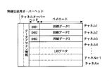
- the radio frame data is configured by overhead for radio transmission (also referred to as “radio frame header”) OHB, overheads OHB1 to OHBn for n channels, and a payload.
- Information necessary for wireless transmission such as frame bits, alarm information, and auxiliary signals, is multiplexed on the wireless transmission overhead OHB.
- one PDH data signal sequence is multiplexed in the payload of one channel, and stuff information and alarm information of one PDH data sequence which is multiplexed in the payload are multiplexed in overheads OHB1 to OHBn of the channel unit. Are multiplexed.
- n wireless PDH data signal sequence inputs (line data input) 101-a to 10 n-a are externally input in the wireless transmission device A.
- the stuff circuits 11-a to 1 n-a connected are synchronized with the radio frame frequency in a stuff synchronous manner, and multiplexed in each channel of the radio frame in the radio frame multiplexing circuit (MUX) 4-a.
- the signal is modulated via the wireless transmission / reception circuit 6-a and output to the wireless transmission path.
- Received data input from the wireless transmission path in the wireless transmission apparatus B is demodulated via the wireless transmission / reception circuit 6-b and input to the wireless frame separation circuit (DEMUX) 5-b.
- the radio frame separation circuit (DEMUX) 5-b extracts the PDH data signal sequence from each channel of the radio frame data, and performs the destuffing operation by the corresponding destuffing circuits 21-b to 2n-b, and the PDH data
- the signal train output (line data output) 201-b to 20n-b is output to the outside of the apparatus as signal line output.
- the LAN termination circuit 3-a receives the input input from the LAN wired transmission paths 301-a to 30m-a.
- Each data is temporarily stored in a reception buffer (not shown), and LAN reception data is output in packet units according to the read control signal, and multiplexed data to a wireless frame is generated according to the mapping control signal 7-a.
- the LAN reception data input from the LAN wired transmission paths 301-a to 30m-a via the reception buffer is output at the multiplex data rate of the channel unit set by the mapping control signal 7-a.
- the LAN reception data input from the LAN wired transmission path 301-a allocates the band of channel 1
- the LAN reception data input from the LAN wired transmission path 302-a is the channel 2 of the payload.
- 3 bands are allocated, and the channels of the remaining payload are allocated as PDH data signal trains.
- the mapping control signal 7-a it is possible to set an independent wireless band for each LAN wired transmission path, and secure a wireless band corresponding to each LAN wired transmission path.
- Patent Document 1 when LAN reception data is assigned to the channel of the wireless frame, not only the payload of the corresponding channel but also the overhead bits of the channel are in the data area of the LAN. It is described that it is possible to increase the transmission capacity of LAN data by assigning as.
- Patent Document 1 The disclosure of Patent Document 1 is incorporated herein by reference. The following gives an analysis of the related art according to the present invention.
- the line data signal sequence and the LAN data are multiplexed into a radio frame and can be transmitted.
- more efficient transmission can be achieved by performing some improvements. It turned out that high throughput can be realized.
- the receiving station for example, the wireless transmission device B in FIG. 6
- data separation serial-parallel conversion
- the mapping control signal is supplied from the upper device (management device) (not shown) to the wireless transmission device of the transmitting station and the receiving station, respectively, and between the transmitting station and the receiving station Inconsistencies may occur in channel assignment.
- a handshake or the like is required between radio frames, resulting in a decrease in throughput of radio frame transmission.
- an object of the present invention is to wirelessly transmit channel data and LAN data wirelessly using a wireless frame, enabling efficient and high-throughput transmission with respect to channel configuration change of the wireless frame.
- a wireless transmission method is provided.
- the invention disclosed in the present application is generally configured as follows in order to solve the above problems.
- a wireless transmission apparatus that transmits a plurality of channel data signal sequences by stuff multiplexing into a wireless frame and transmits the channel assignment information of data in the payload of the wireless frame to the overhead for wireless transmission.
- a wireless transmission device including: means for transmitting by wireless LAN data or LAN data and line data multiplexed in the payload of the wireless frame.
- the LAN data is not subjected to the framing processing performed on the line data signal sequence, and is mapped directly to a radio frame from a buffer storing the LAN data.
- a wireless transmission device comprising means for separating LAN data and line data.
- the payload of the corresponding channel and the overhead bits of the channel are allocated as a data area of the LAN.
- a mapping control signal for a wireless frame is input, and based on the mapping control signal, the PDH (PDH) is mapped by mapping LAN data input from the LAN wired transmission path to a designated transmission area on the wireless frame.
- PDH PDH
- Plesiochronous Digital Hierarchy or SDH (Synchronous Digital Hierarchy) data and LAN data can be simultaneously transmitted.
- the overhead for wireless transmission includes channel assignment information of data in the payload of the wireless frame, LAN data or LAN data and circuit data are multiplexed in the payload of the radio frame and transmitted by radio.
- a wireless transmission method including the above steps is provided.
- the LAN data is mapped to a radio frame directly from a buffer storing the LAN data without being subjected to the framing processing performed on the line data signal sequence.
- LAN data or LAN data multiplexed in the payload portion of the wireless frame based on the channel assignment information.
- a wireless transmission method including the above steps for separating line data and line data.
- the payload of the corresponding channel and the overhead bits of the channel are allocated as a data area of the LAN.
- the present invention by including the channel assignment information of data in the payload of the wireless frame in the wireless overhead, it becomes possible to transmit without interruption regardless of which channel the LAN data is assigned to, high efficiency, high throughput transmission Is possible.
- the overhead bit for radio transmission includes channel allocation information of data in the payload of the radio frame, and LAN data or LAN data and line data in the transmission area of the radio frame.
- Wireless transmission includes channel allocation information of data in the payload of the radio frame, and LAN data or LAN data and line data in the transmission area of the radio frame.
- the payload of the corresponding channel and the overhead bits of the channel are allocated as a data area of the LAN, and the LAN data transmission capacity is increased. Is dynamically assignable to any channel area.
- the LAN data is not directly subjected to PDH E1 framing or the like, and is directly mapped to a radio frame.
- the wireless transmission device on the receiving side separates (serial-to-parallel conversion) the data multiplexed in the wireless frame based on the channel assignment information of the overhead for wireless transmission. Further, according to one aspect of the present invention, a mapping control signal for a wireless frame is input, and based on the mapping control signal, mapping of LAN data input from a LAN wired transmission path to a designated transmission area on the wireless frame is performed. By doing this, it is possible to simultaneously transmit PDH / SDH data and LAN data.
- predetermining the transmission capacity (the number of channels of the PDH data string) and directly multiplexing it on the radio frame eliminates the need for data phasing.
- the read clock of the reception buffer may be changed in accordance with the transmission capacity.
- reception buffer data is read out at the same frequency as the transmission capacity in radio frame units, and multiplexed to the corresponding payload and OHB bit.
- assignment information of LAN data is multiplexed on a wireless transmission overhead.
- MUX serial-parallel conversion
- DEMUX parallel-serial conversion
- the amount of delay (transmission delay) can be reduced and minimized, the transmission capacity can be expanded, instantaneous disconnection due to capacity change can be prevented, and high efficiency and high throughput transmission can be realized.
- the present invention will be described based on the following examples.
- FIG. 1 is a diagram showing the configuration of an embodiment of the present invention.
- wireless transmission devices A and B are devices having a wireless transmission capacity capable of transmitting and receiving n PDH data signal sequences to each other.
- the wireless transmission apparatus A inputs line data, inserts stuff pulses, and performs stuff circuits 11-a to 1 n-a (where n is a predetermined positive integer) for performing synchronization between bit strings, and a wireless frame multiplexing circuit (MUX) ) 4-a, radio frame separation circuit (DEMUX) 5-a, radio transmission / reception circuit 6-a, de-stuffing circuits 21-a to 2 n-a for performing de-stuffing processing (stuff pulse deletion), and LAN termination A circuit 3-a is provided.
- the wireless transmission device B also has the same configuration.
- the transmission side of the wireless transmission device A will be described.
- the PDH data signal sequence input (line data input) 101-a is synchronized with the radio frame frequency in the stuff circuit 11-a in a stuff synchronous manner, and is output to the radio frame multiplex circuit (MUX) 4-a.
- PDH data signal sequence input (line data input) 10n-a is also stuff-synchronized to the radio frame frequency by the corresponding stuff circuit 1n-a and output to radio frame multiplexing circuit (MUX) 4-a.
- the wireless frame multiplexing circuit (MUX) 4-a multiplexes n pieces of PDH data signal sequences after stuff synchronization, which are input from the stuff circuits 11-a to 1 n-a, into a wireless frame transmission area, and transmits and receives wireless signals. Output to the circuit 6-a.
- the radio frame is configured to include overhead required for radio transmission, overhead in units of channels, and a payload, and one PDH data signal train portion is accommodated in the payload of one channel.
- stuff information of PDH data signal sequence multiplexed in the payload and alarm information are multiplexed in the overhead of the channel.
- the LAN termination circuit 3-a is a reception buffer (not shown) for each packet of LAN reception data input from a plurality of LAN wired transmission paths 301-a to 30 m-a (where m is a predetermined positive integer).
- the LAN termination circuit 3-a determines the transmission capacity on the wireless frame side with respect to the LAN wired transmission paths 301-a to 30m-a in units of channels of the wireless frame according to the mapping control signal 7-a.
- the LAN termination circuit 3-a encapsulates the LAN reception data respectively input from the LAN wired transmission paths 301-a to 30m-a in units of packets to generate multiplex data, and generates a wireless frame multiplexing circuit (MUX). ) Output to 4-a.
- MUX wireless frame multiplexing circuit
- the radio frame multiplexing circuit (MUX) 4-a multiplexes multiplexed data input from the LAN termination circuit 3-a into a radio frame transmission area defined by the mapping control signal 7-a. That is, the wireless frame multiplexing circuit (MUX) 4-a assigns each channel of the wireless frame to either the LAN data or the PDH data signal sequence in accordance with the mapping control signal 7-a set from the upper apparatus (not shown) or the like. Decide what to do. Then, the wireless frame multiplexing circuit (MUX) 4-a reads LAN reception data in packet units from the reception buffer of the LAN termination circuit 3-a at the speed of the channel to be assigned as LAN data, and the payload of the designated channel Multiplex.
- the wireless frame multiplexing circuit (MUX) 4-a accommodates a PDH data signal sequence after stuff processing input from the stuffing circuit in the channel assigned as the PDH data signal sequence to form a wireless frame, and wirelessly Output to the transmission / reception circuit 6-a.
- the PDH data signal train (line data) and the LAN data have the payload of the corresponding channel and the overhead bit of the channel when the LAN data is assigned to the channel of the radio frame. All assigned as LAN data area.
- LAN data stored in the buffer (not shown) of the LAN termination circuit is stored as it is in the corresponding channel of the LAN data of the wireless frame (without load on the overhead bits of the channel, phase alignment, etc.) Ru.
- channel assignment information (data assignment information) of data in the payload of the wireless frame is stored in the overhead for wireless transmission.
- radio frame data is generated by assigning as channel overhead + line data transmission area.
- the data assignment information of the overhead for wireless transmission is channel data 1 to 3 for channel data 1 to 3 and channel 4 to channel n for LAN data of a plurality of channels in the wireless frame to be transmitted. It includes information for notifying the opposite receiving apparatus that (the overhead of the channel is a transmission area) is allocated.
- the wireless header creation unit 41-a of the wireless frame multiplexing circuit (MUX) 4-a includes wireless frame configuration information including channel assignment information of the wireless frame in the overhead bit for wireless transmission (OHB).
- Set The created radio frame data (overhead bit for radio transmission and serial bit data of the payload portion) is output to the radio transmission / reception circuit 6-a.
- the radio transmission / reception circuit 6-a modulates the radio frame data, carries it to a radio frequency, and transmits it to the opposite radio transmission apparatus B.
- the data input from the wireless transmission apparatus A through the wireless transmission path is demodulated by the wireless transmission / reception circuit 6-b, synchronized with the wireless frame, and output wireless frame data to the wireless frame separation circuit (DEMUX) 5-b. .
- the radio frame separation circuit (DEMUX) 5-b After radio frame synchronization is established in the radio header analysis unit 51-b of the radio frame separation circuit (DEMUX) 5-b, data allocation of overhead bits (OHB) for radio transmission Assign) The configuration information is analyzed, and the channel to which the LAN data in the wireless frame is assigned and the channel to which the PDH data signal sequence is assigned are separately extracted. Then, the radio frame separation circuit (DEMUX) 5-b is a de-stuffing circuit that corresponds the channel data to which the LAN data is assigned to the LAN termination circuit 3-b and the channel data to which the PDH data signal sequence is assigned. Output to
- the LAN termination circuit 3-b stores LAN data input from the radio frame separation circuit (DEMUX) 5-b in the transmission buffer in units of packets, and outputs the LAN data to the LAN wired transmission paths 301-b to 30m-b.
- the transmission from the wireless transmission device B to A is the same as the transmission from the wireless transmission device A to B, so the description will be omitted.
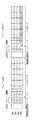
- FIG. 3 is a view for explaining a radio frame according to an embodiment of the present invention.
- LAN data is assigned to channels # 1 to # 4 in the overhead for wireless transmission.
- the numbers in the payload represent the order of serial conversion of parallel bit data.
- LAN data is assigned to channels # 1 to # 3
- line data is assigned to channel # 4.
- channels # 1 to # 3 are LAN and channel # 4 is E1 as data assignment information.
- serial LAN data multiplexed and transmitted in the radio frame separation unit (DEMUX) based on the data assignment information of the overhead for wireless transmission can be expanded to parallel data.
- FIG. 4 is a diagram showing the main part of the configuration of the LAN termination circuit 3-a of FIG.
- the LAN termination circuit 3-b of the wireless transmission device B is also configured in the same manner.
- LAN reception data input from the LAN wired transmission paths 301-a to 30m-a are stored in reception buffers 311 to 31m, respectively.
- the port distribution circuit 8 reads out LAN reception data from the reception buffers 311 to 31m in packet units and encapsulates the data. Then, in accordance with the mapping control signal 7-a, the port distribution circuit 8 designates transmission capacity on the wireless transmission path side with respect to each LAN wired transmission path in channel units of wireless frames, and generates multiplexed data to the payload.
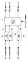
- FIGS. 5 (a) to 5 (c) are diagrams showing configuration examples of the port distribution circuit 8 of FIG. 4, respectively.
- the port distribution circuit 8 collectively outputs LAN reception data 701 to 70m input from a plurality of LAN wired transmission paths, as multiplexed data 801.
- the port distribution circuit 8 outputs individual multiplexed data 801 to 80 m to the LAN reception data 701 to 70 m of each LAN wired transmission line.
- the port distribution circuit 8 collectively outputs a plurality of LAN reception data in a designated combination, and outputs multiplexed data.
- two LAN reception data 701 and 702 are combined into one to output multiplexed data 801, and a plurality of LAN reception data 703 to 70m are aggregated to output one multiplexed data 802. ing.
- a user using a LAN wired transmission line is in the same network, it is possible to increase the utilization efficiency of the wireless band by collectively transmitting in one band of the wireless frame.
- the connection destinations of a plurality of LAN wired transmission paths are separate networks, by independently allocating the band on the wireless side in network units, it is possible to prevent a decrease in throughput due to inflow of unnecessary data from other networks, It is possible to guarantee the transmission band on the wireless side in network units.
- the wireless transmission device has the PDH data signal sequence interface and the LAN interface, and maps the respective data in the channel unit of the wireless frame to obtain the PDH data signal sequence and the LAN data.
- transmission is enabled, and wireless transmission is performed without instantaneous interruption even when the radio frame configuration (LAN data channel allocation, transmission capacity) is changed between the preceding and following radio frames.
- the band on the wireless transmission path side can be set individually for each LAN wired transmission path in channel units of the wireless frame. Can provide services with guaranteed bandwidth.
- PDH data is described as an example of a line data signal sequence multiplexed with LAN data in a wireless frame, but it is of course also applicable to SDH (Synchronous Digital Hierarchy) data as well. It is. That is, according to the present invention, SDH data and LAN data can be multiplexed and wirelessly transmitted to the opposite station.
Abstract
Description
前記無線フレームのペイロードに、LANデータ、又は、LANデータと回線データを多重して無線伝送する、
上記工程を含む無線伝送方法が提供される。
21-a、…2n-a、21-b、…2n-b デスタッフ回路
3-a、3-b LAN終端回路
4-a、4-b 無線フレーム多重回路(MUX)
41-a、41-b 無線ヘッダ作成部
5-a、5-b 無線フレーム分離回路(DEMUX)
51-a、51-b 無線ヘッダ解析部
6-a、6-b 無線送受信回路
7-a、7-b マッピング制御信号
8 ポート振り分け回路
101-a、…10n-a、101-b、…10n-b 回線データ入力
201-a、…20n-a、201-b、…20n-b 回線データ出力
301-a、…30m-a、301-b、…30m-b LAN有線伝送路
311、312、…31m 受信バッファ
701、702、…70m LAN受信データ
801、802、…80m 多重データ
Claims (13)
- 複数の回線データ信号列を無線フレームにスタッフ多重して伝送する無線伝送装置であって、
無線伝送用オーバーヘッドに、無線フレームのペイロードにおけるデータのチャネル割当情報を含ませ、前記無線フレームのペイロードに、LANデータ、又は、LANデータと回線データを多重して無線伝送する手段を備えている、ことを特徴とする無線伝送装置。 - 前記LANデータは、前記回線データ信号列に対して為されるフレーミング処理を受けず、前記LANデータを格納するバッファから、直接、無線フレームにマッピングされる、ことを特徴とする請求項1記載の無線伝送装置。
- 無線伝送用オーバーヘッドにデータのチャネル割当情報を含む無線フレームを受信した場合、前記チャネル割当情報に基づき、前記無線フレームのペイロードに多重された、LANデータ、又は、LANデータと回線データを分離する手段を備えている、ことを特徴とする無線伝送装置。
- 前記無線フレームにLANデータを割り当てる場合に、該当するチャネルのペイロードとチャネルのオーバーヘッドビットとがともにLANデータ領域として、割り当てられる、ことを特徴とする請求項1乃至3のいずれか1項に記載の無線伝送装置。
- 前記回線データは、PDH(Plesiochronous Digital Hierarchy)又はSDH(Synchronous Digital Hierarchy)データである、ことを特徴とする請求項1乃至4のいずれか1項に記載の無線伝送装置。
- 前記無線フレームに対するマッピング制御信号を入力し、前記マッピング制御信号に基づき、LAN有線伝送路から入力されるLANデータを、無線フレーム上の指定した伝送領域にマッピングするLAN終端回路を備え、PDH(Plesiochronous Digital Hierarchy)又はSDH(Synchronous Digital Hierarchy)データとLANデータとを同時に伝送可能としてなる、ことを特徴とする請求項1乃至5のいずれか1項に記載の無線伝送装置。
- 無線伝送用オーバーヘッドに、無線フレームのペイロードにおけるデータのチャネル割当情報を含ませ、
前記無線フレームのペイロードに、LANデータ、又は、LANデータと回線データを多重して無線伝送する、
ことを特徴とする無線伝送方法。 - 前記LANデータは、前記回線データ信号列に対して為されるフレーミング処理を受けず、前記LANデータを格納するバッファから、直接に、無線フレームにマッピングされる、ことを特徴とする請求項7記載の無線伝送方法。
- 前記無線フレームのオーバーヘッダにデータのチャネル割当情報を含む無線フレームを受信した場合、前記チャネル割当情報に基づき、前記無線フレームのペイロードに多重された、LANデータ、又は、LANデータと回線データを分離する、ことを特徴とする無線伝送方法。
- 前記無線フレームにLANデータを割り当てる場合に、該当するチャネルのペイロードとチャネルのオーバーヘッドビットとがLANのデータ領域として、割り当てられる、ことを特徴とする請求項7乃至9のいずれか1項に記載の無線伝送方法。
- 前記回線データは、PDH(Plesiochronous Digital Hierarchy)又はSDH(Synchronous Digital Hierarchy)データである、ことを特徴とする請求項7乃至10のいずれか1項に記載の無線伝送方法。
- 無線フレームに対するマッピング制御信号を入力し、前記マッピング制御信号に基づき、LAN有線伝送路から入力されるLANデータを、無線フレーム上の指定した伝送領域にマッピングすることにより、PDH(Plesiochronous Digital Hierarchy)又はSDH(Synchronous Digital Hierarchy)データとLANデータとを同時に伝送可能としてなる、ことを特徴とする請求項7乃至11のいずれか1項に記載の無線伝送方法。
- 無線伝送用オーバーヘッドに、無線フレームのペイロードにおける、少なくともLANデータのチャネル割当情報を含ませ、前記無線フレームのペイロードに、LANデータ、又は、LANデータと回線データを多重して無線伝送する送信装置と、
無線伝送用オーバーヘッドにチャネル割当情報を含む無線フレームを受信した場合、前記チャネル割当情報に基づき、前記無線フレームのペイロードに多重されたデータを分離する受信装置と、
を備えている、ことを特徴とする無線伝送システム。
Priority Applications (6)
| Application Number | Priority Date | Filing Date | Title |
|---|---|---|---|
| US12/866,221 US20100322221A1 (en) | 2008-02-08 | 2008-02-08 | Radio transmitting device and radio transmission method |
| CN2008801260761A CN101933262A (zh) | 2008-02-08 | 2008-02-08 | 无线传输装置以及无线传输方法 |
| JP2009552371A JP5610510B2 (ja) | 2008-02-08 | 2008-02-08 | 無線伝送装置及び無線伝送方法 |
| PCT/JP2008/052188 WO2009098783A1 (ja) | 2008-02-08 | 2008-02-08 | 無線伝送装置及び無線伝送方法 |
| RU2010137272/07A RU2476999C2 (ru) | 2008-02-08 | 2008-02-08 | Передающее устройство радиосвязи и способ радиопередачи |
| EP08711067.2A EP2247008A4 (en) | 2008-02-08 | 2008-02-08 | Radio transmitting device and radio transmitting method |
Applications Claiming Priority (1)
| Application Number | Priority Date | Filing Date | Title |
|---|---|---|---|
| PCT/JP2008/052188 WO2009098783A1 (ja) | 2008-02-08 | 2008-02-08 | 無線伝送装置及び無線伝送方法 |
Publications (1)
| Publication Number | Publication Date |
|---|---|
| WO2009098783A1 true WO2009098783A1 (ja) | 2009-08-13 |
Family
ID=40951871
Family Applications (1)
| Application Number | Title | Priority Date | Filing Date |
|---|---|---|---|
| PCT/JP2008/052188 WO2009098783A1 (ja) | 2008-02-08 | 2008-02-08 | 無線伝送装置及び無線伝送方法 |
Country Status (6)
| Country | Link |
|---|---|
| US (1) | US20100322221A1 (ja) |
| EP (1) | EP2247008A4 (ja) |
| JP (1) | JP5610510B2 (ja) |
| CN (1) | CN101933262A (ja) |
| RU (1) | RU2476999C2 (ja) |
| WO (1) | WO2009098783A1 (ja) |
Cited By (1)
| Publication number | Priority date | Publication date | Assignee | Title |
|---|---|---|---|---|
| KR20140053311A (ko) * | 2011-08-17 | 2014-05-07 | 텔레폰악티에볼라겟엘엠에릭슨(펍) | 인코더 역량의 동적인 시그날링 매카니즘 |
Families Citing this family (3)
| Publication number | Priority date | Publication date | Assignee | Title |
|---|---|---|---|---|
| US9602433B2 (en) * | 2012-07-26 | 2017-03-21 | Qualcomm Incorporated | Systems and methods for sharing a serial communication port between a plurality of communication channels |
| US8835310B2 (en) * | 2012-12-21 | 2014-09-16 | Intermolecular, Inc. | Two step deposition of molybdenum dioxide electrode for high quality dielectric stacks |
| JP6401062B2 (ja) | 2015-01-06 | 2018-10-03 | Kddi株式会社 | 無線通信装置、無線通信方法およびプログラム |
Citations (3)
| Publication number | Priority date | Publication date | Assignee | Title |
|---|---|---|---|---|
| JPH05316119A (ja) * | 1992-05-06 | 1993-11-26 | Fujitsu Ltd | バースト・データ通信方式 |
| JP2005244328A (ja) | 2004-02-24 | 2005-09-08 | Nec Corp | 無線伝送装置及び方法 |
| JP2006203439A (ja) * | 2005-01-19 | 2006-08-03 | Nec Corp | 無線伝送装置及び方法 |
Family Cites Families (5)
| Publication number | Priority date | Publication date | Assignee | Title |
|---|---|---|---|---|
| JPH01213043A (ja) * | 1988-02-22 | 1989-08-25 | Sumitomo Electric Ind Ltd | 高速データ多重化伝送方式 |
| JPH04207426A (ja) * | 1990-11-30 | 1992-07-29 | Hitachi Ltd | フレーム同期方式 |
| US6522671B1 (en) * | 1999-05-10 | 2003-02-18 | Nortel Networks Limited | Protocol independent sub-rate device |
| RU2213424C1 (ru) * | 2002-04-24 | 2003-09-27 | Военный университет связи | Устройство приема и обработки информации |
| US7483432B2 (en) * | 2002-09-23 | 2009-01-27 | Alcatel Lucent Usa Inc. | Packet transport arrangement for the transmission of multiplexed channelized packet signals |
-
2008
- 2008-02-08 EP EP08711067.2A patent/EP2247008A4/en not_active Withdrawn
- 2008-02-08 US US12/866,221 patent/US20100322221A1/en not_active Abandoned
- 2008-02-08 WO PCT/JP2008/052188 patent/WO2009098783A1/ja active Application Filing
- 2008-02-08 JP JP2009552371A patent/JP5610510B2/ja not_active Expired - Fee Related
- 2008-02-08 RU RU2010137272/07A patent/RU2476999C2/ru not_active IP Right Cessation
- 2008-02-08 CN CN2008801260761A patent/CN101933262A/zh active Pending
Patent Citations (3)
| Publication number | Priority date | Publication date | Assignee | Title |
|---|---|---|---|---|
| JPH05316119A (ja) * | 1992-05-06 | 1993-11-26 | Fujitsu Ltd | バースト・データ通信方式 |
| JP2005244328A (ja) | 2004-02-24 | 2005-09-08 | Nec Corp | 無線伝送装置及び方法 |
| JP2006203439A (ja) * | 2005-01-19 | 2006-08-03 | Nec Corp | 無線伝送装置及び方法 |
Non-Patent Citations (1)
| Title |
|---|
| See also references of EP2247008A4 |
Cited By (2)
| Publication number | Priority date | Publication date | Assignee | Title |
|---|---|---|---|---|
| KR20140053311A (ko) * | 2011-08-17 | 2014-05-07 | 텔레폰악티에볼라겟엘엠에릭슨(펍) | 인코더 역량의 동적인 시그날링 매카니즘 |
| KR102034321B1 (ko) * | 2011-08-17 | 2019-10-18 | 텔레폰악티에볼라겟엘엠에릭슨(펍) | 인코더 역량의 동적인 시그날링 매카니즘 |
Also Published As
| Publication number | Publication date |
|---|---|
| JPWO2009098783A1 (ja) | 2011-05-26 |
| EP2247008A1 (en) | 2010-11-03 |
| JP5610510B2 (ja) | 2014-10-22 |
| EP2247008A4 (en) | 2017-05-17 |
| RU2010137272A (ru) | 2012-03-20 |
| US20100322221A1 (en) | 2010-12-23 |
| RU2476999C2 (ru) | 2013-02-27 |
| CN101933262A (zh) | 2010-12-29 |
Similar Documents
| Publication | Publication Date | Title |
|---|---|---|
| US7822075B2 (en) | Method and system of signal transmission in base transceiver station based on remote radio head | |
| CN108353314B (zh) | 切换用于通过提供回程和前传两者(xhaul)连接性的传输网络的传输的至少两个类型的数据信号 | |
| US7817603B2 (en) | Method and apparatus for multi-antenna signal transmission in RF long-distance wireless BS | |
| EP2430804B1 (en) | Universal service transport transitional encoding | |
| US7590153B2 (en) | Protocol independent sub-rate device | |
| US7133415B2 (en) | SONET circuit emulation with VT compression | |
| JP2008042731A (ja) | 伝送装置 | |
| US20090245292A1 (en) | Clock recovery apparatus and method | |
| JP4740259B2 (ja) | Pdhおよびパケット・データを多重化するためのシステムおよび方法 | |
| US8514775B2 (en) | System and method for improving the use of radio spectrum in transmission of data | |
| WO2009098783A1 (ja) | 無線伝送装置及び無線伝送方法 | |
| EP1083692A2 (en) | Inter-chip port and method for supporting high rate data streams in SDH and SONET transport networks | |
| EP1701495B1 (en) | Hybrid digital cross-connect for switching circuit and packet based data traffic | |
| US20010021171A1 (en) | Transmission unit and two-way signal conversion method | |
| JP5320017B2 (ja) | 伝送装置 | |
| JP4800012B2 (ja) | 光通信システム及び端末装置 | |
| JP4586379B2 (ja) | 無線伝送装置及び方法 | |
| WO2010055547A1 (ja) | 伝送装置 | |
| US7778285B2 (en) | Method and apparatus for extraction and insertion of plesiochronous overhead data | |
| US7558260B2 (en) | Byte-timeslot-synchronous, dynamically switched multi-source-node data transport bus system | |
| US6915348B1 (en) | Validation of a connection between arbitrary end-points in a communications network using an augmented SPE | |
| KR100549596B1 (ko) | 이더넷 신호-ds3급 신호 다중/역다중 장치 | |
| JP5322029B2 (ja) | バーチャルコンカチネーションのsq処理方法、その伝送装置及び伝送システム |
Legal Events
| Date | Code | Title | Description |
|---|---|---|---|
| WWE | Wipo information: entry into national phase |
Ref document number: 200880126076.1 Country of ref document: CN |
|
| 121 | Ep: the epo has been informed by wipo that ep was designated in this application |
Ref document number: 08711067 Country of ref document: EP Kind code of ref document: A1 |
|
| WWE | Wipo information: entry into national phase |
Ref document number: 2009552371 Country of ref document: JP |
|
| WWE | Wipo information: entry into national phase |
Ref document number: 12866221 Country of ref document: US |
|
| NENP | Non-entry into the national phase |
Ref country code: DE |
|
| WWE | Wipo information: entry into national phase |
Ref document number: 5497/CHENP/2010 Country of ref document: IN |
|
| REEP | Request for entry into the european phase |
Ref document number: 2008711067 Country of ref document: EP |
|
| WWE | Wipo information: entry into national phase |
Ref document number: 2008711067 Country of ref document: EP |
|
| WWE | Wipo information: entry into national phase |
Ref document number: 2010137272 Country of ref document: RU |