WO2009096415A1 - 電子機器、遠隔制御システム、信号処理方法、制御プログラムおよび記録媒体 - Google Patents
電子機器、遠隔制御システム、信号処理方法、制御プログラムおよび記録媒体 Download PDFInfo
- Publication number
- WO2009096415A1 WO2009096415A1 PCT/JP2009/051331 JP2009051331W WO2009096415A1 WO 2009096415 A1 WO2009096415 A1 WO 2009096415A1 JP 2009051331 W JP2009051331 W JP 2009051331W WO 2009096415 A1 WO2009096415 A1 WO 2009096415A1
- Authority
- WO
- WIPO (PCT)
- Prior art keywords
- signal
- command signal
- unit
- remote control
- electronic device
- Prior art date
- Legal status (The legal status is an assumption and is not a legal conclusion. Google has not performed a legal analysis and makes no representation as to the accuracy of the status listed.)
- Ceased
Links
Images


Classifications
-
- G—PHYSICS
- G08—SIGNALLING
- G08C—TRANSMISSION SYSTEMS FOR MEASURED VALUES, CONTROL OR SIMILAR SIGNALS
- G08C17/00—Arrangements for transmitting signals characterised by the use of a wireless electrical link
-
- H—ELECTRICITY
- H04—ELECTRIC COMMUNICATION TECHNIQUE
- H04N—PICTORIAL COMMUNICATION, e.g. TELEVISION
- H04N1/00—Scanning, transmission or reproduction of documents or the like, e.g. facsimile transmission; Details thereof
- H04N1/00127—Connection or combination of a still picture apparatus with another apparatus, e.g. for storage, processing or transmission of still picture signals or of information associated with a still picture
- H04N1/00281—Connection or combination of a still picture apparatus with another apparatus, e.g. for storage, processing or transmission of still picture signals or of information associated with a still picture with a telecommunication apparatus, e.g. a switched network of teleprinters for the distribution of text-based information, a selective call terminal
- H04N1/00283—Connection or combination of a still picture apparatus with another apparatus, e.g. for storage, processing or transmission of still picture signals or of information associated with a still picture with a telecommunication apparatus, e.g. a switched network of teleprinters for the distribution of text-based information, a selective call terminal with a television apparatus
- H04N1/00297—Connection or combination of a still picture apparatus with another apparatus, e.g. for storage, processing or transmission of still picture signals or of information associated with a still picture with a telecommunication apparatus, e.g. a switched network of teleprinters for the distribution of text-based information, a selective call terminal with a television apparatus with a television signal recorder, e.g. for recording facsimile images on a VCR
-
- H—ELECTRICITY
- H04—ELECTRIC COMMUNICATION TECHNIQUE
- H04N—PICTORIAL COMMUNICATION, e.g. TELEVISION
- H04N21/00—Selective content distribution, e.g. interactive television or video on demand [VOD]
- H04N21/40—Client devices specifically adapted for the reception of or interaction with content, e.g. set-top-box [STB]; Operations thereof
- H04N21/41—Structure of client; Structure of client peripherals
- H04N21/4104—Peripherals receiving signals from specially adapted client devices
- H04N21/4126—The peripheral being portable, e.g. PDAs or mobile phones
- H04N21/41265—The peripheral being portable, e.g. PDAs or mobile phones having a remote control device for bidirectional communication between the remote control device and client device
-
- H—ELECTRICITY
- H04—ELECTRIC COMMUNICATION TECHNIQUE
- H04N—PICTORIAL COMMUNICATION, e.g. TELEVISION
- H04N21/00—Selective content distribution, e.g. interactive television or video on demand [VOD]
- H04N21/40—Client devices specifically adapted for the reception of or interaction with content, e.g. set-top-box [STB]; Operations thereof
- H04N21/41—Structure of client; Structure of client peripherals
- H04N21/4104—Peripherals receiving signals from specially adapted client devices
- H04N21/4135—Peripherals receiving signals from specially adapted client devices external recorder
-
- H—ELECTRICITY
- H04—ELECTRIC COMMUNICATION TECHNIQUE
- H04N—PICTORIAL COMMUNICATION, e.g. TELEVISION
- H04N21/00—Selective content distribution, e.g. interactive television or video on demand [VOD]
- H04N21/40—Client devices specifically adapted for the reception of or interaction with content, e.g. set-top-box [STB]; Operations thereof
- H04N21/41—Structure of client; Structure of client peripherals
- H04N21/414—Specialised client platforms, e.g. receiver in car or embedded in a mobile appliance
- H04N21/41407—Specialised client platforms, e.g. receiver in car or embedded in a mobile appliance embedded in a portable device, e.g. video client on a mobile phone, PDA, laptop
-
- H—ELECTRICITY
- H04—ELECTRIC COMMUNICATION TECHNIQUE
- H04N—PICTORIAL COMMUNICATION, e.g. TELEVISION
- H04N21/00—Selective content distribution, e.g. interactive television or video on demand [VOD]
- H04N21/40—Client devices specifically adapted for the reception of or interaction with content, e.g. set-top-box [STB]; Operations thereof
- H04N21/41—Structure of client; Structure of client peripherals
- H04N21/422—Input-only peripherals, i.e. input devices connected to specially adapted client devices, e.g. global positioning system [GPS]
- H04N21/42204—User interfaces specially adapted for controlling a client device through a remote control device; Remote control devices therefor
-
- H—ELECTRICITY
- H04—ELECTRIC COMMUNICATION TECHNIQUE
- H04N—PICTORIAL COMMUNICATION, e.g. TELEVISION
- H04N21/00—Selective content distribution, e.g. interactive television or video on demand [VOD]
- H04N21/40—Client devices specifically adapted for the reception of or interaction with content, e.g. set-top-box [STB]; Operations thereof
- H04N21/41—Structure of client; Structure of client peripherals
- H04N21/426—Internal components of the client ; Characteristics thereof
-
- H—ELECTRICITY
- H04—ELECTRIC COMMUNICATION TECHNIQUE
- H04N—PICTORIAL COMMUNICATION, e.g. TELEVISION
- H04N21/00—Selective content distribution, e.g. interactive television or video on demand [VOD]
- H04N21/40—Client devices specifically adapted for the reception of or interaction with content, e.g. set-top-box [STB]; Operations thereof
- H04N21/43—Processing of content or additional data, e.g. demultiplexing additional data from a digital video stream; Elementary client operations, e.g. monitoring of home network or synchronising decoder's clock; Client middleware
- H04N21/436—Interfacing a local distribution network, e.g. communicating with another STB or one or more peripheral devices inside the home
- H04N21/4363—Adapting the video stream to a specific local network, e.g. a Bluetooth® network
- H04N21/43637—Adapting the video stream to a specific local network, e.g. a Bluetooth® network involving a wireless protocol, e.g. Bluetooth, RF or wireless LAN [IEEE 802.11]
-
- H—ELECTRICITY
- H04—ELECTRIC COMMUNICATION TECHNIQUE
- H04N—PICTORIAL COMMUNICATION, e.g. TELEVISION
- H04N7/00—Television systems
- H04N7/16—Analogue secrecy systems; Analogue subscription systems
- H04N7/162—Authorising the user terminal, e.g. by paying; Registering the use of a subscription channel, e.g. billing
- H04N7/163—Authorising the user terminal, e.g. by paying; Registering the use of a subscription channel, e.g. billing by receiver means only
-
- G—PHYSICS
- G08—SIGNALLING
- G08C—TRANSMISSION SYSTEMS FOR MEASURED VALUES, CONTROL OR SIMILAR SIGNALS
- G08C2201/00—Transmission systems of control signals via wireless link
- G08C2201/40—Remote control systems using repeaters, converters, gateways
-
- H—ELECTRICITY
- H04—ELECTRIC COMMUNICATION TECHNIQUE
- H04N—PICTORIAL COMMUNICATION, e.g. TELEVISION
- H04N1/00—Scanning, transmission or reproduction of documents or the like, e.g. facsimile transmission; Details thereof
- H04N1/00127—Connection or combination of a still picture apparatus with another apparatus, e.g. for storage, processing or transmission of still picture signals or of information associated with a still picture
- H04N1/00281—Connection or combination of a still picture apparatus with another apparatus, e.g. for storage, processing or transmission of still picture signals or of information associated with a still picture with a telecommunication apparatus, e.g. a switched network of teleprinters for the distribution of text-based information, a selective call terminal
- H04N1/00283—Connection or combination of a still picture apparatus with another apparatus, e.g. for storage, processing or transmission of still picture signals or of information associated with a still picture with a telecommunication apparatus, e.g. a switched network of teleprinters for the distribution of text-based information, a selective call terminal with a television apparatus
- H04N1/00291—Connection or combination of a still picture apparatus with another apparatus, e.g. for storage, processing or transmission of still picture signals or of information associated with a still picture with a telecommunication apparatus, e.g. a switched network of teleprinters for the distribution of text-based information, a selective call terminal with a television apparatus with receiver circuitry
-
- H—ELECTRICITY
- H04—ELECTRIC COMMUNICATION TECHNIQUE
- H04N—PICTORIAL COMMUNICATION, e.g. TELEVISION
- H04N1/00—Scanning, transmission or reproduction of documents or the like, e.g. facsimile transmission; Details thereof
- H04N1/00127—Connection or combination of a still picture apparatus with another apparatus, e.g. for storage, processing or transmission of still picture signals or of information associated with a still picture
- H04N1/00281—Connection or combination of a still picture apparatus with another apparatus, e.g. for storage, processing or transmission of still picture signals or of information associated with a still picture with a telecommunication apparatus, e.g. a switched network of teleprinters for the distribution of text-based information, a selective call terminal
- H04N1/00307—Connection or combination of a still picture apparatus with another apparatus, e.g. for storage, processing or transmission of still picture signals or of information associated with a still picture with a telecommunication apparatus, e.g. a switched network of teleprinters for the distribution of text-based information, a selective call terminal with a mobile telephone apparatus
-
- H—ELECTRICITY
- H04—ELECTRIC COMMUNICATION TECHNIQUE
- H04N—PICTORIAL COMMUNICATION, e.g. TELEVISION
- H04N2201/00—Indexing scheme relating to scanning, transmission or reproduction of documents or the like, and to details thereof
- H04N2201/0008—Connection or combination of a still picture apparatus with another apparatus
- H04N2201/0013—Arrangements for the control of the connected apparatus by the still picture apparatus
-
- H—ELECTRICITY
- H04—ELECTRIC COMMUNICATION TECHNIQUE
- H04N—PICTORIAL COMMUNICATION, e.g. TELEVISION
- H04N2201/00—Indexing scheme relating to scanning, transmission or reproduction of documents or the like, and to details thereof
- H04N2201/0008—Connection or combination of a still picture apparatus with another apparatus
- H04N2201/0015—Control of image communication with the connected apparatus, e.g. signalling capability
-
- H—ELECTRICITY
- H04—ELECTRIC COMMUNICATION TECHNIQUE
- H04N—PICTORIAL COMMUNICATION, e.g. TELEVISION
- H04N2201/00—Indexing scheme relating to scanning, transmission or reproduction of documents or the like, and to details thereof
- H04N2201/0008—Connection or combination of a still picture apparatus with another apparatus
- H04N2201/0034—Details of the connection, e.g. connector, interface
- H04N2201/0037—Topological details of the connection
- H04N2201/0043—Point to multipoint
-
- H—ELECTRICITY
- H04—ELECTRIC COMMUNICATION TECHNIQUE
- H04N—PICTORIAL COMMUNICATION, e.g. TELEVISION
- H04N2201/00—Indexing scheme relating to scanning, transmission or reproduction of documents or the like, and to details thereof
- H04N2201/0008—Connection or combination of a still picture apparatus with another apparatus
- H04N2201/0034—Details of the connection, e.g. connector, interface
- H04N2201/0044—Connecting to a plurality of different apparatus; Using a plurality of different connectors
-
- H—ELECTRICITY
- H04—ELECTRIC COMMUNICATION TECHNIQUE
- H04N—PICTORIAL COMMUNICATION, e.g. TELEVISION
- H04N2201/00—Indexing scheme relating to scanning, transmission or reproduction of documents or the like, and to details thereof
- H04N2201/0008—Connection or combination of a still picture apparatus with another apparatus
- H04N2201/0034—Details of the connection, e.g. connector, interface
- H04N2201/0048—Type of connection
- H04N2201/0055—By radio
-
- H—ELECTRICITY
- H04—ELECTRIC COMMUNICATION TECHNIQUE
- H04N—PICTORIAL COMMUNICATION, e.g. TELEVISION
- H04N2201/00—Indexing scheme relating to scanning, transmission or reproduction of documents or the like, and to details thereof
- H04N2201/0077—Types of the still picture apparatus
- H04N2201/0084—Digital still camera
Definitions
- the present invention relates to an electronic device that processes a signal, a remote control system, a signal processing method, a control program, and a recording medium.
- command signals are transmitted from a remote control device (remote control) to a plurality of controlled devices by infrared data communication to perform remote operation.
- Non-Patent Document 1 Non-Patent Document 1
- the devices are interconnected via an interface realized by wire or wireless, and signal exchange is realized in one direction or in both directions by the connection between the devices.
- AV devices are connected using a digital video / audio input / output interface such as HDMI (High Definition Multimedia Interface), and video / audio / command signals can be transmitted and received.
- a digital video / audio input / output interface such as HDMI (High Definition Multimedia Interface)
- video / audio / command signals can be transmitted and received.
- the AV device can control other AV devices or operate according to instructions from other AV devices (for example, Non-Patent Document 2).
- a device A electronic device
- a device B controlled device
- signals command signals
- a remote control system connected via a specific interface so that a processing target signal such as a video / audio signal can be transmitted.
- each device when each device is installed in a state where both devices can receive one command signal from the remote controller (for example, each device is installed in a state where the infrared light receiving unit is very close).
- the device B is assumed to be a signal directed to itself, so that a problem of malfunction occurs in that the command signal is received and processed.
- the command of the command signal of the remote controller is, for example, the content “Make device A perform processing X”
- device A receives a plurality of signals in response to this one command. Accordingly, there arises a problem that the process X is executed once, multiple times.
- the device A transmits (1) a command signal for instructing the processing X transmitted from the remote controller and (2) the device B transmits to the device A via the interface according to the command signal from the remote controller.
- the command signal (or the processing target signal of the processing X) for instructing is received in duplicate.
- the command signal directly input to the device A is the original target command signal, wasteful processing occurs for the device A that performs processing repeatedly, which is not preferable for the entire system. Even if the original intended command signal is input to the device B, useless processing still occurs in each device.
- the above-mentioned problems are not limited to AV devices that process digital signals, but also occur in controlled devices that can receive a plurality of signals in duplicate for one command of the remote controller.
- the present invention has been made in view of the above-described problems, and an object of the present invention is to provide a remote operation system capable of receiving a plurality of command signals corresponding to electronic devices for one command signal of a remote controller.
- An electronic device, a remote control system, a signal processing method, a control program, and a recording medium capable of appropriately processing each signal received by the electronic device so that the electronic device operates only based on a signal to be followed It is to be realized.
- an electronic device of the present invention is an electronic device that constitutes a remote control system together with a remote control device and at least one controlled device that receives a direct command signal broadcast by the remote control device.
- a first receiving unit that receives a direct command signal broadcast from the remote control device to the electronic device and the one or more controlled devices; and the controlled device receives the remote control device from the remote control device.
- a second receiving unit that receives an indirect command signal generated according to the direct command signal from each of the one or more controlled devices, the direct command signal received by the first receiving unit, and the second From the signal group consisting of the one or more indirect command signals received by the receiving unit, the original command signal that requires a response is predetermined. It is characterized by comprising a control unit and a single selection signal selecting means in accordance with the rules.
- the electronic device and the controlled device installed within the command signal output range receive the same direct command signal. To do.
- the electronic device receives the direct command signal at the first receiving unit.
- the controlled device generates an indirect command signal according to the received direct command signal.
- the controlled device transmits the generated indirect command signal to the electronic device.
- the electronic device receives the indirect command signal at the second receiving unit.
- the indirect command signal is received by the number of controlled devices provided in the remote control system.
- one direct command signal directly received from the remote control device and one or more indirect command signals corresponding to the direct command signal are input to the electronic device.
- one command signal is transmitted from the remote control device. Therefore, in this signal group, there is only one original signal to be answered, and other signals are duplicate signals that should be ignored.
- the signal selection means selects one original command signal to be responded from among a plurality of command signals belonging to the signal group according to a predetermined rule.
- the electronic device receives a signal group including a plurality of overlapping command signals for one command signal of the remote control device, it is possible to appropriately select the original command signal to be followed by the electronic device. It becomes possible. Therefore, it is possible to prevent redundant processing from being performed in the electronic device.
- a remote control system of the present invention includes a remote control device, at least one controlled device that receives a direct command signal broadcast by the remote control device, and any one of the electronic devices described above. Equipment.
- the signal processing method of the present invention is an electronic device that constitutes a remote control system together with a remote control device and at least one controlled device that receives a direct command signal broadcast by the remote control device.
- a direct command signal receiving step for receiving a direct command signal broadcast-transmitted from the remote control device to the electronic device and the one or more controlled devices; and
- the indirect command signal generated according to the direct command signal received from the remote control device is received from each of the one or more controlled devices, and the direct command signal is received in the direct command signal receiving step.
- the direct command signal and the one or more received in the indirect command signal receiving step From the signal group consisting of contact instruction signal, it is characterized by comprising a signal selecting step of selecting one according to the response the inherent command signal a predetermined rule required.
- an electronic device of the present invention is an electronic device that constitutes a remote control system together with a remote control device and at least one controlled device that receives a direct command signal broadcast by the remote control device.
- a first receiving unit that receives a direct command signal broadcast from the remote control device to the electronic device and the one or more controlled devices; and the controlled device receives the remote control device from the remote control device.
- a second receiving unit that receives an indirect command signal generated according to the direct command signal from each of the one or more controlled devices, the direct command signal received by the first receiving unit, and the second From the signal group consisting of the one or more indirect command signals received by the receiving unit, the original command signal that requires a response is predetermined. It is characterized by comprising a control unit and a single selection signal selecting means in accordance with the rules.
- a remote control system of the present invention includes a remote control device, at least one controlled device that receives a direct command signal broadcast by the remote control device, and any one of the electronic devices described above. Equipment.
- the signal processing method of the present invention is an electronic device that constitutes a remote control system together with a remote control device and at least one controlled device that receives a direct command signal broadcast by the remote control device.
- a direct command signal receiving step for receiving a direct command signal broadcast-transmitted from the remote control device to the electronic device and the one or more controlled devices; and
- the indirect command signal generated according to the direct command signal received from the remote control device is received from each of the one or more controlled devices, and the direct command signal is received in the direct command signal receiving step.
- the direct command signal and the one or more received in the indirect command signal receiving step From the signal group consisting of contact instruction signal, it is characterized by comprising a signal selecting step of selecting one according to the response the inherent command signal a predetermined rule required.
- the electronic device operates based only on the signal to be followed. There is an effect that each signal received by the electronic device can be appropriately processed.
- FIG. 3 is a data structure diagram schematically showing a data structure of image data.
- 3 is a data structure diagram schematically showing a data structure of operation image data.
- FIG. It is a block diagram which shows schematic structure of the digital television in embodiment of this invention.
- FIG. 1 It is a sequence diagram which shows the transmission / reception timing of each signal of the mobile telephone, the digital television, HDD recorder, and STB which comprise the photograph display system in other embodiment of this invention. It is a flowchart which shows the flow of a process of the digital television in other embodiment of this invention.
- (A)-(c) is a figure which shows the specific example of the signal management table of a certain time in the digital television of other embodiment of this invention. It is a flowchart which shows the flow of a process of the digital television in other embodiment of this invention.
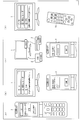
- (A)-(d) is a figure which shows the example of the menu screen for making a user specify the desired apparatus which should process operation image data before a mobile telephone transmits operation image data. .
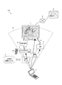
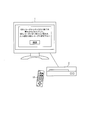
- FIG. 2 is a diagram showing a schematic configuration of the photograph display system 100 in the embodiment of the present invention.
- the photo display system 100 is a system for displaying a photo on the digital television 1, and any device that is communicably connected to the digital television 1 can provide the digital television 1 with a photo.
- the photograph display system 100 in the present embodiment includes a digital television 1, a hard disk (HDD) recorder 2, a set-top box (STB) 2 ′, a mobile phone 3, and a service providing server 4 as shown in FIG. Yes.
- the digital television 1, HDD recorder 2, and STB 2 ′ are AV devices installed in the home, and each device has a function of receiving infrared data transmitted from the mobile phone 3 and performing an operation corresponding thereto. ing.
- the mobile phone 3 transmits infrared data, that is, image data 7 or operation image data 7 ′ to each device using IrSS (registered trademark) communication, which is a high-speed infrared communication protocol.
- IrSS (registered trademark) communication is an example, and other wireless communication capable of broadcasting may be used.
- the digital TV 1 and other devices are connected via the HDMI cable 6, and the devices connected via the HDMI cable 6 are connected with video. Signals, audio signals, and command signals can be transmitted and received together.
- the HDD recorder 2 can convert an image or a moving image stored in its own device (or received from the mobile phone 3) into a video signal and output it as an HDMI signal 8 to the digital television 1.
- the connection using the HDMI cable is an example, and may be a wired connection such as an Ethernet (registered trademark) cable or a PLC, or a wireless connection such as a wireless LAN.
- the digital television 1 has a function of communicating with an external device such as the service providing server 4 via an external communication network such as the Internet 5. Thereby, the digital television 1 can receive various services provided by the service providing server 4.
- the service providing server 4 provides a “network album service” for displaying a photograph taken with a digital camera or the like on the digital television 1 like an album.
- the service providing server 4 provides the digital television 1 with an application (hereinafter referred to as a network photo application) for distributing photos or displaying photos via the Internet 5.
- each AV device installed in the home can also be operated by the operation unit 18 as a conventional remote controller.
- Complex functions recording reservation from the EPG of the digital television 1, program recording / playback of the HDD recorder 2, etc.
- each AV device may also be operated via the operation unit 18.
- the photo display system 100 it is possible to provide and display a photo on the digital television 1 through various communication means included in each device.
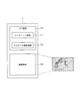
- FIG. 3 is a data structure diagram schematically showing the data structure of the image data 7.
- the image data 7 is JPEG format data including an image area 720 and an EXIF area 710.
- the image area 720 is an area for compressing and storing image information to be displayed.
- the EXIF information 710 is an area for storing meta information related to image information stored in the image area 720.
- the EXIF area 710 includes a manufacturer note area 711 that can be freely used by a manufacturer such as a digital camera.
- the EXIF area 710 includes a thumbnail image area 712 for storing a thumbnail image obtained by reducing the main image stored in the image area 720.
- the mobile phone 3 can display the image included in the image data 7 on the digital television 1 by directly transmitting the image data 7 in the JPEG format shown in FIG.
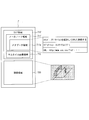
- FIG. 4 is a data structure diagram schematically showing the data structure of the operation image data (direct command signal) 7 '.
- the operation image data 7 ′ is JPEG format data including an image area 720 and an EXIF area 710 ′. This point is common to the image data 7.
- the difference between the image data 7 'for operation and the image data 7 is that it includes processing designation information which is a command for causing each AV device to execute a specific operation. That is, if the mobile phone 3 transmits the operation image data 7 ′ to the digital television 1, the AV device can perform all operations other than the operation of displaying the image stored in the image area 720. 3 can be used like a remote control.
- the operation image data 7 ′ used for operating each AV device is realized by storing the processing designation information in the maker note area 711 ′ described above.
- the process designation information is stored in a specific area (here, the metadata area 711a) secured in the maker note area 711 '.
- a specific area here, the metadata area 711a
- the processing designation information may be stored in another application area or comment area.
- the format of the operation image data 7 ′ including the processing designation information is not limited to JPEG format data.
- the mobile phone 3 can start the application on the digital television 1 and display the page of the URL by transmitting the operation image data 7 ′ shown in FIG. 4 to the digital television 1.
- the contents of the image area 720 and the thumbnail image area 712 may be irrelevant to the contents of the processing (processing designation information) that the digital television 1 wants to execute. That is, the image area 720 and the thumbnail image area 712 can be freely used when it is desired to transmit the processing designation information to the target device.
- an image expressing the content of the process specified by the process specifying information stored in the maker note area 711 ', that is, an icon image may be stored.
- the operation image data 7 ′ is displayed in the same manner as the normal image data 7 on the mobile phone 3, the user is informed of what is stored in the operation image data 7 ′. It becomes possible to do.
- the image area 720 and the thumbnail image area 712 may store images such as photographs to be displayed, just like the image data 7.
- the digital television 1 that has received the operation image data 7 ′ displays the image of the operation image data 7 ′ (the image stored in the image area 720) and displays the image. It is possible to perform image processing designated by the processing designation information of the operation image data 7 ′.
- both the conventional digital television 1 and the HDD recorder 2 are installed in a state where the image data 7 from the mobile phone 3 can be received, one problem arises. That is, as described above, there is a problem that a plurality of command signals are input to the digital television 1 in duplicate with respect to one command of the mobile phone 3.
- the digital television 1 that has received the image data 7 processes the image data 7 to process and display the image stored in the image area 720.
- the HDD recorder 2 processes the image stored in the image area 720 to generate a video signal, and outputs it to the digital television 1 as an HDMI signal 8 together with an input switching request signal for requesting switching of the input to the own device. To do.
- the digital television 1 performs a process of displaying a video signal from the HDD recorder 2 in accordance with the input switching request signal (for example, P171 of Non-Patent Document 3).
- the digital television 1 can directly respond to the infrared signal from the mobile phone 3 and display the video signal sent through the HDD recorder 2 even though the image can be displayed. An image will be displayed.
- the digital television 1 that has received the operation image data 7 ′ shown in FIG. 4 processes the operation image data 7 ′ and instructs “execute application and connect to URL”. Operates according to processing specification information. For example, the network photo application is activated, connected to the service providing server 4, and the album page designated by the URL is displayed (result A). On the other hand, if the HDD recorder 2 does not support the function of analyzing the processing designation information, the HDMI signal 8 is processed in order to process the image stored in the image area 720 and display it as described above. Is output to the digital television 1. The digital television 1 switches the input to the HDD recorder 2 in response to the input switching request signal from the HDD recorder 2 and displays the image in the image area 720 (result B).
- the result B is output instead of the result A by the input switching operation of the digital television 1. This means that the photo display system 100 is not operating as intended by the user, and the system is not established. Even if the result B is a result desired by the user, useless processing for outputting the result A occurs in the digital television 1, which is not preferable for the system.
- the digital television 1 includes a signal processing device for appropriately processing each signal.
- the schematic structure of the digital television 1 provided with the signal processing apparatus is demonstrated first.
- FIG. 5 is a block diagram showing a schematic configuration of the digital television 1 in the embodiment of the present invention.
- the digital television 1 includes a main control unit 10, a video switching unit 11, a display control unit 12, a display unit 13, an application group 14, an OSD processing unit 15, a storage unit 16, a temporary storage unit 17, an operation signal.
- Reception unit 19 infrared communication unit 20, image data analysis unit 21, video signal conversion unit 22, HDMI signal processing unit 23, communication unit 24, communication data processing unit 25, broadcast data reception unit 26, and broadcast data processing unit 27 It is the composition provided with.
- the main control unit 10 controls various operations of each unit included in the digital television 1.
- the main control unit 10 reads various programs recorded in the storage unit 16 or each application included in the application group 14 and controls each unit of the digital television 1 of the present invention to realize various functions provided in the digital television 1. To do. Details of the main control unit 10 operating as the signal processing apparatus of the present invention will be described later.
- the storage unit 16 is executed by the main control unit 10 (1) a control program for each unit, (2) an OS program, (3) an application program, (4) a signal processing function program as a signal processing device of the present invention, and Various data read when these programs are executed is recorded.
- the storage unit 16 is configured by a nonvolatile storage device such as a flash memory.
- the temporary storage unit 17 is composed of a volatile storage device such as a RAM, and is used as a work area for temporarily holding data in the course of the main control unit 10 executing the various programs described above.
- the application group 14 shows a specific example of applications stored in the storage unit 16.
- the digital television 1 has a web browser function, an image (photo) display function, an electronic program guide (EPG) output / processing function, and a network album display function.
- the main control unit 10 executes the image display application 142, the EPG application 143, and the network photo application 144.
- the network photo application 144 is one of services provided by the service providing server 4.
- the network photo application 144 of the service providing server 4 is not limited, and various network service applications 145 may be acquired from various external service providing servers.
- the execution result of each application is appropriately converted into a video signal and transmitted to the video switching unit 11.
- the result is transmitted to the OSD processing unit 15.
- the operation signal receiving unit 19 receives the operation signal transmitted from the operation unit 18 and transmits it to the main control unit 10.
- the operation signal is an infrared signal
- it is realized by an infrared light receiving unit that receives infrared light and converts it into an electrical signal.
- the infrared communication unit 20 receives image data (image data 7, operation image data 7 ') transmitted from the mobile phone 3. More specifically, the infrared communication unit 20 is configured to include an infrared light receiving unit that receives infrared light emitted from the mobile phone 3 and converts the infrared light into an electric signal. Image data transmitted from the mobile phone 3 is obtained by converting the signal into digital data according to a predetermined infrared communication protocol (for example, IrSS communication). Image data received by the infrared communication unit 20 is stored in the storage unit 16 and processed by the image data analysis unit 21 as necessary.
- a predetermined infrared communication protocol for example, IrSS communication
- the image data analysis unit 21 analyzes the image data received by the infrared communication unit 20. More specifically, the image data analysis unit 21 analyzes the data structure of the image data (FIGS. 3 and 4), and extracts an image to be displayed from the image area 720 or the thumbnail image area 712. The processing designation information is extracted from the metadata area 711a of the maker note area 711. The processing designation information extracted by the image data analysis unit 21 is transmitted to the main control unit 10. Further, the image extracted as a display target is transmitted to the video signal conversion unit 22. When the received image data does not include the processing designation information, the image data analysis unit 21 does not include the processing designation information instead of transmitting the processing designation information. The main control unit 10 is notified that the image in the image area 720 should be displayed. On the other hand, when the process designation information is included, if the contents of the process designated by the process designation information and the image stored in the image area 720 are completely unrelated, the image data analysis unit 21 The image may not be transmitted to the video signal converter 22.
- the video signal conversion unit 22 converts the image extracted by the image data analysis unit 21 into a video signal composed of RGB signals for display on the display unit 13 of the digital television 1.
- the image converted into the video signal by the video signal conversion unit 22 is transmitted to the video switching unit 11.
- the HDMI signal processing unit 23 is connected to an earlier device (for example, HDD recorder 2) connected via the HDMI cable 6 via an HDMI terminal (second receiving unit) (not shown) provided in the digital television 1.
- the HDMI signal 8 transmitted from is received and processed.
- the HDMI signal processing unit 23 acquires, from the HDMI signal, a command signal (such as the above input switching request) for controlling the operation of the digital television 1, a video signal to be processed, an audio signal, and the like.
- the command signal acquired by the HDMI signal processing unit 23 is transmitted to the main control unit 10.
- the video signal is transmitted to the video switching unit 11.
- the audio signal is transmitted to an audio output control unit and a speaker (not shown).
- the digital television 1 includes an HDMI terminal for receiving an HDMI signal and an HDMI signal processing unit 23 for each connected device.
- the HDMI signal from the STB 2 ′ is also input to the digital television 1 through the terminal for the HDMI signal and processed by the HDMI signal processing unit 23 for the HDMI signal.
- the HDMI signal processing unit 23 can grasp from which device the received signal is the HDMI signal based on the header information of the transmission source included in the HDMI signal.
- the communication unit 24 transmits / receives data to / from an external device via a wide-area communication network such as the Internet 5.
- various services provided from the service providing server 4 are received. Specifically, it receives data described in a page description language such as XML (eXtensible Markup Language) or HTML and photo data (display data) to be displayed.
- the display data received by the communication unit 24 is transmitted to the communication data processing unit 25.
- the communication unit 24 may receive communication data of any format that can be supported by each application of the application group 14 installed in the digital television 1.
- the communication data received via the communication unit 24 is appropriately transmitted by the communication data processing unit 25 to each unit capable of processing it according to the format.
- the communication data processing unit 25 analyzes display data and communication data received by the communication unit 24, transmits a command signal as a result of the analysis to the main control unit 10, a photograph or an image to be subjected to display processing, and the like Is transmitted to an appropriate application execution unit of the main control unit 10.
- the broadcast data receiving unit 26 receives a digital broadcast signal broadcast from the broadcast station 9 via an antenna. Specifically, it is composed of a channel selection unit, a digital tuner unit, a demodulation unit, and the like.
- the broadcast data processing unit 27 is a TS separation unit that decodes multiplexed digital data received by the broadcast data reception unit 26 and extracts a TS.
- Each TS packet includes data signals such as program information and information necessary for channel selection in addition to video / audio signals.
- the broadcast data processing unit 27 separates the TS packets according to purpose, and the TS signals including video / audio signals are processed by the video switching unit 11 and the audio output control unit, respectively, and by the application group 14. Is transmitted to the main control unit 10.
- the video switching unit 11 switches the input to an appropriate video signal in accordance with a command signal from the main control unit 10 (thick line) among a plurality of input video signals (one-dot chain line) and displays the video on the display unit 13
- the signal is output to the display control unit 12.
- the video signal input to the video switching unit 11 is, for example, a plurality of video signals from the above-described units (communication data processing unit 25 (application group 14), video signal conversion unit 22, HDMI signal processing unit 23, broadcast data processing unit 27, etc.). Is output.
- the OSD processing unit 15 performs a superimposition process for superimposing an OSD (on-screen display) image as a processing execution result of the application group 14 on a video signal output from the video switching unit 11.
- an electronic program guide (EPG) and a menu screen (GUI image) for the user to operate the digital television 1 are superimposed here.
- the display control unit 12 controls the display unit 13 to display the video signal output from the video switching unit 11 (the video signal on which the OSD image from the OSD processing unit 15 is superimposed as necessary) on the display unit 13. Is.
- the display control unit 12 temporarily writes display screen drawing data to be output to the display unit 13 to a temporary storage unit 17 constituted by a volatile storage device such as a RAM, and a frame buffer (not shown) for each screen. )).
- the display unit 13 displays various data such as photographs, OSD images, application execution results, and display data.
- an LCD liquid crystal display
- PDP plasma display panel
- CRT cathode-ray tube
- Consists of a display device such as a display.
- the signal processing apparatus of the present invention for solving the above-described problem is realized by the main control unit 10 reading the signal processing function program stored in the storage unit 16 into the temporary storage unit 17 and executing it.
- movement of the main-control part 10 as a signal processing apparatus are demonstrated in detail.
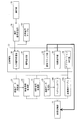
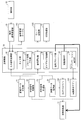
- FIG. 1 is a block diagram showing a main configuration of a main control unit 10 as a signal processing device of the present invention.
- the main control unit 10 includes an input signal management unit 30, a signal selection unit 31, a signal block unit 32, a switching instruction unit 33, and an application execution unit 34.
- the reference numerals given to the respective constituent elements shown in FIG. 1 correspond to the reference numerals given to the respective constituent elements in FIG. 5, and the same reference numerals indicate the same constituent elements. Therefore, the description about the component already demonstrated is not repeated.
- the input signal management unit 30 manages signals transmitted from the respective units of the digital television 1 to the main control unit 10. That is, the input signal management unit 30 manages input signals from all connected devices that can be connected to the digital television 1 in the home in the photo display system 100. More specifically, in the example shown in FIG. 2, all the above-mentioned connected devices are the mobile phone 3, the HDD recorder 2, and the STB 2 ′, so the input signal management unit 30 is stored in the storage unit 16.
- the signal management table 161 is used to manage input signals for each connected device.
- the main control unit 10 can grasp all of the video signals input to the video switching unit 11 in response to one command. Then, only one target signal that is the original one, that is, one original command signal (hereinafter referred to as a favorite signal) that requires a response is selected from the one signal group.
- the signal selection unit 31 receives a plurality of signals input to the digital television 1 (main control unit 10) by transmitting one command (image data 7 or operation image data 7 ′) from the mobile phone 3.
- a target signal that is an original one, that is, a favorite signal, is selected based on a predetermined rule from the signal group including the plurality of signals.
- each time the signal of each signal group is received it may be determined whether or not the signal is a favorite signal.
- the signal selection unit 31 performs signal selection or determination with reference to information in the signal management table 161 and predetermined rules.
- the signal block unit 32 blocks the input of a video signal derived from a signal other than the favorite signal selected by the signal selection unit 31 to the video switching unit 11 for a predetermined period.
- the block of the video signal is executed by controlling the video switching unit 11 to block the video signal output from each member such as the video signal conversion unit 22.
- the signal block unit 32 may control each member so that no video signal is output.
- the command signal itself may be discarded so that the command signal for instructing the output of the video signal is not supplied to each member that outputs the video signal.
- the signal block unit 32 may discard the video signal output by each member.
- the signal block unit 32 is a command signal that is not selected by the signal selection unit 31 during the period in which the digital television 1 is executing the processing of the favorite signal, that is, the non-fatal signal (and the Video signal) is blocked.
- the switching instruction unit 33 instructs the video switching unit 11 to switch the input to the video signal derived from the favorite signal selected by the signal selection unit 31 as necessary.
- the configuration may be such that only the member that outputs the favorite video signal is allowed to output the video signal to the video switching unit 11.
- the application execution unit 34 executes each application (for example, the network photo application 144, the image display application 142, etc.) included in the application group 14.
- the application execution unit 34 activates the image display application 142 and the image of the image data 7.
- a process of displaying the image stored in the area 720 is executed. If the image display application has already been activated, the activation process may be omitted.
- the operation image data 7 ′ includes process designation information, and the “Start Network Photo App and Connect to URL” process is designated, the application execution unit 34 performs the network photo.
- the application 144 is activated, the album page provided by the service providing server 4 is received via the communication data processing unit 25, and the network photo application 144 performs processing for displaying the album. If the network photo application is already activated, the activation process may be omitted.
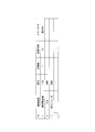
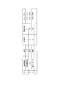
- FIG. 6 is a diagram illustrating a specific example of the signal management table 161 referred to by the signal selection unit 31.
- the state of the signal management table 161 at a certain time point (t1) after the command signal (image data 7 or operation image data 7 ′) is transmitted from the mobile phone 3 (t0) is shown. ing.
- signals from the three devices described above are managed as one signal group.
- the names “ID” and “connected device” may be anything as long as the digital television 1 can uniquely identify each device connected to the digital television 1.
- the “arrival order” represents the order in which signals arrive at the digital television 1 (input signal management unit 30) in one signal group.
- the “arrival time” represents the time when the signal reaches the input signal management unit 30.
- the arrival time shown in FIG. 6 may store the time indicated by a clock unit (not shown) provided in the digital television 1, or the time when the signal arrives first is set to 0, and the subsequent signals arrive. You may store the relative elapsed time of a time.
- the “status” stores status information indicating what state the digital television 1 has entered (what operation has been performed) when the signal arrives at the digital television 1.
- the status information stored in the “status” field and its definition are as follows, for example. “Executing” Processing is being executed to respond to the signal. “Execution completed” The above processing is completed, and the response to the signal is completed. “Blocking” Processing is being performed to respond to the signal, or the response to the signal has been completed, but blocking processing of the non-fatal signal of the same group is continuing (ie, the block period) Inside). “Blocked” The signal has been blocked for a non-fatal signal. “Hold” Since the signal cannot be determined to be true or non-fatal at that time, processing is suspended.
- the above-described status information is an example, and the present invention is not limited to this.
- the signal processing device of the present invention there are no particular restrictions on the rules that the signal selection unit 31 conforms to when selecting a favorite signal.
- the operation of the main control unit 10 is performed in the case of executing signal processing based on the rule 1 that “the first signal input to the digital television 1 in the signal group is a favorite signal”. This will be described in detail. In the following description, it is assumed that a predetermined period (block period) during which a signal is blocked is defined as “during execution of data processing for a favorite signal”.
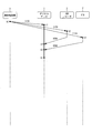
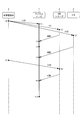
- FIG. 7 shows each period from the time when the command signal is transmitted from the mobile phone 3 (t0) until the digital television 1 completes the processing according to the favorite signal while blocking the non-critical signal (t6). It is a sequence diagram which shows the timing of transmission / reception of the signal of an apparatus.
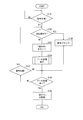
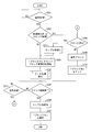
- FIG. 8 is a flowchart showing a processing flow of the digital television 1 from the time when the digital television 1 receives the first command signal (t1) until the processing is executed and completed according to the favorite signal (t6).
- a thick line from time t1 to time t6 in the digital television 1 indicates a period during which processing is executed in accordance with the received signal command.
- the digital television 1 receives the image data 7 from the mobile phone 3 as an IrSS signal at t1, the HDD recorder 2 at t2, and the STB 2 ′ at t3. To do.
- each AV device HDMI-connected to the digital television 1 processes the image data 7, when the digital television 1 receives a signal at t1 (here, the signal t1) as shown in FIG.
- the signal processing is started so as to appropriately respond to the signal (and other signals belonging to the signal group).
- the input signal management unit 30 detects that the IrSS signal is input from the mobile phone 3 at t1, and registers the information in the signal management table 161.
- the signal t1 is the first signal
- the input signal management unit 30 associates status information “in execution” indicating that data processing is being executed in response to the signal t 1 from the mobile phone 3 with the mobile phone 3, in the signal management table 161.
- the main control unit 10 executes data processing according to the instruction of the signal t1 (S104).
- the application execution unit 34 activates the image display application 142 and starts a process of displaying an image included in the image data 7 (thick lines t1 to t6 in FIG. 7).
- the input signal management unit 30 receives the signal t4.
- the signal selection unit 31 determines whether or not the signal t4 is a favorite signal in S102. In the example shown here, since the digital television 1 is already executing data processing on the signal t1, the signal selection unit 31 recognizes that the signal t4 is not the first signal in the signal group, and satisfies the above rule 1. Therefore, it is determined that the signal is a non-fatal signal to be blocked (YES in S102).
- the signal block unit 32 blocks the signal t4 so that the signal t4 is not processed in the digital television 1 (S108). Specifically, blocking the signal means discarding the signal t4 stored in the storage unit 16, instructing the video switching unit 11 not to switch the input to the video signal derived from the signal t4, For example, the signal t4 may be blocked from being supplied to each unit (the video signal conversion unit 22 and the image display application 142) that processes t4, or the processing of the signal t4 may be prohibited for each unit.
- the input signal management unit 30 sets status information “blocked” in association with the HDD recorder 2 in the signal management table 161.
- the input signal management unit 30 When the data processing ends (YES in S105, t6 in FIG. 7), the input signal management unit 30 initializes the signal management table 161 and cancels the “in-execution” information in the signal t1 (S106). .
- the block period is defined as “during the execution of data processing for the favorite signal”, that is, “data reception processing period + JPEG image development display processing period” has been described.
- the block period defined in the apparatus is not limited to this.
- only the IrSS signal reception processing period may be defined as the block period.
- the signal selection unit 31 may select the favorite signal based on the type of signal. For example, according to the rule 2 “Make IrSS signal a favorite signal”, another type of signal belonging to the same signal group as the IrSS signal, such as an HDMI signal, can be determined as a non-critical signal. A block period can be set during the IrSS signal processing period.
- the operation image data 7 ′ including the processing designation information is received by the digital television 1 instead of the mere image data 7, the operation image data 7 ′ is being processed. It can be a block period.
- Such operation image data 7 ′ is image data invited to a specific website, and is therefore referred to as an IrSS invitation.
- the period during which the IrSS invitation is being received or processed may be set as the block period.
- the processing period of the IrSS invitation includes a data analysis time, a corresponding application activation time, a meta information processing time (in the case of a browser, a display time of a specified URL page), and the like.
- FIG. 9 is a block diagram showing a main configuration of the main control unit 10 as the signal processing device of the present invention. As shown in FIG. 9, the main control unit 10 may further include a timer unit 35.
- the timer unit 35 measures an elapsed time after a predetermined event occurs. Specifically, a predetermined period from the time when processing of the favorite signal is completed, or a predetermined period after the first signal reaches the digital television 1 is measured.
- the predetermined period measured by the timer unit 35 is referred to as a block period.
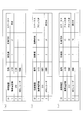
- FIG. 10 is a diagram illustrating another specific example of the signal management table 161 referred to by the signal selection unit 31.
- status information “in block” is stored in association with the signal t1 of the mobile phone 3. This is because the signal t1 is the first signal, so that it is determined as a favorite signal and data processing has been executed (being executed), or the execution of data processing has ended, but the timer unit 35 counts time. Indicates that it is in the block period.
- the input signal management unit 30 sets the “blocking” information until the timer unit 35 notifies the end of the block period. Based on this information, the signal selection unit 31 can recognize how long the received signal should be blocked.
- the main controller 10 of the present invention can be configured not to block the second round signal transmitted from the same device after blocking the non-fatal signal of the same signal group. This is based on the idea that only one signal per device is finally input to the digital television 1 by the IrSS signal output from the mobile phone 3 in one operation. That is, there is only one non-fatal signal in the same signal group as the main signal, and the signal processing is appropriately performed by blocking once. Even during the block period, when the signal is sent again from the same device that has already completed the signal block, it means that another operation is newly performed in the mobile phone 3. . That is, it is a signal of another signal group.
- the input signal management unit 30 determines that the signal group is different, the input signal management unit 30 resets the signal management table 161 in order to manage a new signal group. Thereby, the signal selection unit 31 can correctly determine the favorite / non-critical signal of the new signal group.
- FIG. 11 shows a period from the time when the command signal is transmitted from the mobile phone 3 (t0) until the process is executed and completed according to the favorite signal (t5), and a predetermined block period (t5 to t5) counted by the timer unit. It is a sequence diagram which shows the transmission / reception timing of the signal of each apparatus in t10).
- FIG. 12 shows the processing of the digital television 1 from the time when the digital television 1 receives the first command signal (t1) to the completion of the processing according to the favorite signal (t5) until the block period elapses (t10). It is a flowchart which shows the flow.
- a double line from time t5 to time t10 in the digital television 1 indicates a block period after completion of data processing.
- the infrared communication unit 20 transmits the IrSS signal as shown in FIG. Receive at t1 (YES in S201).
- the input signal management unit 30 registers the received IrSS signal in the signal management table 161 as the signal t1.
- the signal selection unit 31 determines whether or not the registered signal t1 is a favorite signal. That is, at time t1, it is determined whether or not the data processing of the favorite signal of the same signal group is already in progress or the block period is continued after the data processing is executed.
- the signal selection unit 31 determines that it is neither during the execution of the data processing nor during the block period based on the signal management table 161 and the rule 1 (NO in S202)
- the signal t1 is the first one. Since it is a signal, it is determined that it is a favorite signal.
- the input signal management unit 30 associates the status information “in block” indicating that the signal t1 is in the block period with the mobile phone 3 (signal t1) and performs signal management.
- the data is stored in the table 161 (S203).
- the timer unit 35 starts counting a predetermined block period (t1 to t10 in FIG. 11).
- the main control unit 10 (for example, the application execution unit 34) executes data processing according to the instruction of the signal t1 (S204, thick lines t1 to t5 in FIG. 11).
- the input signal management unit 30 receives the signal t6. Is registered in the signal management table 161 in association with the STB 2 ′.
- input signal management section 30 determines that signal t6 is in the second round (another signal group). .
- the signal selection unit 31 determines that the signal t6 is a favorite signal according to the determination of the input signal management unit 30.
- the input signal management unit 30 initializes the signal management table 161 and re-registers the signal t6 (S211). For the signal t6, the above-described steps after S203 are executed.
- the signal selection unit 31 determines that the signal t6 is not the first signal and determines that it is a non-fatal signal according to the rule 1.
- the signal block unit 32 blocks the signal t6 so that the signal t6 is not processed in the digital television 1 according to the determination of the signal selection unit 31 (S209).
- the input signal management unit 30 sets the status information “blocked” of the signal t6 in association with the STB 2 ′ in the signal management table 161 (S210, FIG. 10).
- the input signal management unit 30 initializes the signal management table 161 (S206), and releases the “in block” information in the signal t1. (S207).
- the input is performed at time t4. It is possible to appropriately block not only the HDMI signal to be input but also the HDMI signal input at t6.
- the input signal management unit 30 indicates that the second round is a signal of a new signal group. Therefore, the signal selection unit 31 can make an appropriate determination for a signal that should not be blocked.
- the storage unit 16 includes a mode storage unit 162.
- the mode storage unit 162 stores information on which device the digital television 1 has responded to immediately before (the operation mode of the digital television 1). Specifically, when the digital television 1 executes some data processing in response to the IrSS signal from the mobile phone 3 immediately before, the information of “IrSS response mode” is stored as the immediately preceding operation mode. When responding to the HDMI signal from the HDD recorder 2, information on the “recorder output mode” is stored. When responding to the HDMI signal from the STB 2 ', information on the "STB output mode" is stored.
- the signal selection unit 31 selects a favorite signal according to the immediately preceding operation mode stored in the mode storage unit 162 regardless of the arrival order of the signals. Specifically, among the signals of the same signal group received within a predetermined period (within the block period) counted by the timer unit 35, the signal is supplied from the same device as the device in the previous operation mode stored in the mode storage unit 162. The selected signal is selected as the favorite signal.
- the signal selection unit 31 If the signal selection unit 31 does not receive a signal from a device that matches the previous operation mode within the block period, the signal selection unit 31 regards the signal that has arrived first among the received signals as a favorite signal and performs data processing. Execute. Then, the signal selection unit 31 updates the mode storage unit 162 to the mode of the device that is the source of the favorite signal.
- the timer unit 35 starts timing from the time when the first signal is received, and continues timing until the predetermined block period expires.
- an appropriate time should be set so that the block period is not too short or too long. If the set block period is too short, a signal to be blocked is overlooked, and conversely, if it is too long, a signal that should not be blocked is blocked.
- Each signal belonging to the same signal group is normally input to the digital television 1 in a short period of time, so that the block has a natural length that can be regarded as a signal group within that period and can be said to have no problem. It is preferable to set the period in advance. For example, a fixed time parameter may be given to the timer unit 35 such as 5 seconds or 10 seconds after the first command is received.
- the switching instruction unit 33 when not receiving all the signals of the same signal group, gives an input switching instruction to the video signal derived from the favorite signal according to the specification of the signal selecting unit 31 when the favorite signal is specified. Transmit to the video switching unit 11.
- 13A to 13C are diagrams showing specific examples of the signal management table 161 at a certain point in time in the present embodiment.
- the input signal management unit 30 sets the status information “pending” of the IrSS signal ((a) of FIG. 13).
- the signal selection unit 31 When the signal selection unit 31 receives the HDMI signal from the HDD recorder 2, the signal selection unit 31 recognizes that the HDMI signal is from the device that matches the immediately preceding operation mode stored in the mode storage unit 162, and the HDMI signal is designated It is determined that the IrSS signal is a non-fatal signal.
- the input signal management unit 30 updates the status information of each signal according to the determination result ((b) in FIG. 13). After identifying the favorite signal, the signal selection unit 31 can immediately determine the subsequent signal of the same signal group as the non-designated signal ((c) in FIG. 13).
- FIG. 14 is a sequence diagram showing signal transmission / reception timing of each device from when the command signal is transmitted from the mobile phone 3 (t0) until the digital television 1 expires the block period (t7).
- FIG. 15 is a flowchart showing a processing flow of the digital television 1 from the time when the digital television 1 receives the first command signal to the time (t1) until the block period expires (t7).
- the infrared communication unit 20 receives the IrSS signal at t1 as shown in FIG. 15 (YES in S301).
- the input signal management unit 30 registers the received IrSS signal as the signal t1 in the signal management table 161, and the signal t1 is the first signal depending on whether the signal is already registered in the signal management table 161. It is determined whether it is a signal.
- the signal selection unit 31 determines whether or not the transmission source device (here, the mobile phone 3) of the signal t1 matches the device indicated in the previous operation mode stored in the mode storage unit 162. Determination is made (S304).
- the signal selection unit 31 determines that the signal t1 in S314. It is determined whether or not the favorite signal is confirmed in the signal group. That is, it is determined whether or not data processing is being executed or has been executed in response to the favorite signal.
- the signal selection unit 31 puts the determination on hold (S315, (a) of FIG. 13). If the block period counted by the timer unit 35 has not ended (NO in S310), the main control unit 10 returns to a state of waiting for a subsequent signal (S313).
- the HDD recorder 2 transmits an HDMI signal to the digital television 1 in response to the IrSS signal received at t2.
- the input signal management unit 30 registers the signal t4 in the signal management table 161.
- the signal selection unit 31 determines in S304 that the transmission source device (HDD recorder 2) of the signal t4 matches the device indicated in the previous operation mode of the mode storage unit 162 (YES in S304). According to the rule 3, the signal t4 is determined as a favorite signal.
- the input signal management unit 30 sets “in progress” to the status information associated with the HDD recorder 2 (signal t4) in the signal management table 161 based on the determination of the signal selection unit 31 (S305).
- the application execution unit 34 executes data processing according to the favorite signal selected by the signal selection unit 31 (S306).
- the signal blocking unit 32 blocks it (S307).
- the signal t1 that was “pending” in S315 is blocked.
- the input signal management unit 30 updates the status information of the signal t1 from “pending” to “blocked” (S308, (b) of FIG. 13).
- the application execution unit 34 completes the response to the signal t4
- the input signal management unit 30 may update the status information of the signal t4 from “being executed” to “executed” (S309). If the block period counted by the timer unit 35 has not ended (NO in S310), the main control unit 10 returns to a state of waiting for a subsequent signal (S313).
- the STB 2 transmits an HDMI signal to the digital television 1 in response to the IrSS signal received at t3.
- the input signal management unit 30 registers the signal t 5 in the signal management table 161.
- the transmission source device of the signal t5 does not match the device in the previous operation mode (NO in S304), and the favorite signal has already been determined and data processing is being executed (YES in S314).
- the signal selection unit 31 determines that the signal t5 is a candidate for a non-fatal signal that should be blocked.
- the signal selection unit 31 recognizes the signal t5 as the second cycle and recognizes it as the favorite signal, and sets the mode.
- the immediately preceding operation mode of the storage unit 162 is updated (S316). Further, the input signal management unit 30 initializes the signal management table 161. And the process after S303 is performed similarly to having mentioned above.
- the signal selection unit 31 determines that the signal t5 is a non-fatal signal.
- the signal block unit 32 blocks the signal t5 according to the determination of the signal selection unit 31 (S318).
- the input signal management unit 30 sets “blocked” in the status information associated with STB 2 ′ (signal t 5) in the signal management table 161 (S 319, (c) of FIG. 13).
- the signal selection unit 31 refers to the signal management table 161 and sets “pending”. It is checked whether the signal is not managed (S311).
- the “pending” signal remains (YES in S311), this means that the favorite signal having the same previous operation mode in the series of signals of the same signal group has not been received within the predetermined period. That is, a “pending” signal different from the previous operation mode is regarded as a favorite signal.
- the signal selection unit 31 selects a signal first input to the digital television 1 as a favorite signal from among the signals in “pending”, and transmits the selected signal as the previous operation mode of the mode storage unit 162.
- the operation mode is updated to the new previous operation mode corresponding to the original device (S316).
- the input signal management unit 30 appropriately selects the favorite signal and appropriately blocks the non-critical signal in the signal group within the block period. It is determined that the processing has been done, the signal management table 161 is initialized, and the process is terminated.
- the user even if duplicate signals are input to the digital TV 1 from various devices, the user appropriately specifies one favorite signal in the operation mode in which the user has used the digital TV 1 until immediately before, and It is possible to appropriately block the overlapping signals.
- the signal that is first input to the digital television 1 among the signals in the signal group is an IrSS signal when the operation image data 7 ′ transmitted from the mobile phone 3 is directly received.
- the data structure of the operation image data 7 ′ in this embodiment is as follows.
- device designation information is included in the metadata area 711 a of the operation image data 7 ′ transmitted from the mobile phone 3.
- the device designation information is information for designating which target device should process the operation image data 7 '.
- the image data analysis unit 21 shown in FIG. 9 analyzes the operation image data 7 ′ received from the mobile phone 3 and transmits the extracted device designation information to the main control unit 10.
- the main control unit 10 can appropriately process overlapping signals based on this device designation information.
- the timer unit 35 is given a fixed time parameter in advance, counts the time indicated by the time parameter after the first command is received, and determines the block period. Notify each part of the main control unit 10.
- the signal block unit 32 blocks a signal determined to be a non-fatal signal based on the determination of the signal selection unit 31.
- the switching instruction unit 33 transmits an input switching instruction to the video signal derived from the signal determined as the favorite signal by the signal selection unit 31 to the switching instruction unit 33.
- FIG. 16 are diagrams showing specific examples of the signal management table 161 at a certain point in time in this embodiment.
- FIG. 17 is a flowchart showing a processing flow of the digital television 1 from when the digital television 1 receives the IrSS signal as the first command signal until the block period expires.
- the infrared communication unit 20 receives the IrSS signal at t1, as shown in FIG. (YES in S401 and S402).
- the image data analysis unit 21 analyzes the operation image data 7 'received by the infrared communication unit 20, and extracts device designation information from the metadata area 711a (S403).
- the input signal management unit 30 initializes the signal management table 161 (S404), and registers the received IrSS signal in association with the mobile phone 3 as the signal t1. At this time, information about the target device may be registered for each device based on the device designation information analyzed by the image data analysis unit 21. For example, when the HDD recorder 2 is designated as the target device in the device designation information, the input signal management unit 30 sets a flag indicating that the device is the target device in the “target device” field of the HDD recorder 2. Set ((a) of FIG. 16). This determination is performed by the signal selection unit 31. Further, here, the timer unit 35 starts measuring time from t1, and the signal selection unit 31 starts an operation during the block period (S404).
- the signal selection unit 31 compares the transmission source device (mobile phone 3) of the signal t1 with the target device (HDD recorder 2) indicated in the supplied device designation information, and if they do not match, The signal t1 is determined as a non-fatal signal (NO in S405).
- the signal block unit 32 blocks the signal t1 according to the determination of the signal selection unit 31 (S413).
- the input signal management unit 30 sets the status information “blocked” in association with the mobile phone 3 (signal t1) in the signal management table 161 (S414). If the block period timed by the timer unit 35 has not ended (NO in S409), the main control unit 10 returns to a state of waiting for a subsequent signal (S411). As described above, when the received signal is already blocked in S412 (YES in S412), the input signal management unit 30 determines that the signal should not be blocked in another signal group. The timekeeping times of the signal management table 161 and the timer unit 35 are reset (S415), and are appropriately processed by new signal processing.
- the HDD recorder 2 transmits an HDMI signal to the digital television 1 in response to the IrSS signal received at t2.
- the input signal management unit 30 registers the signal t4 in the signal management table 161.
- the signal selection unit 31 determines that the transmission source device (HDD recorder 2) of the signal t4 matches the target device indicated in the device designation information (YES in S405), and the above rule 4 Accordingly, the signal t4 is determined as a favorite signal.
- the input signal management unit 30 sets “in progress” in the status information associated with the HDD recorder 2 (signal t4) in the signal management table 161 (S406, FIG. 16). (B)).
- the application execution unit 34 executes data processing according to the favorite signal selected by the signal selection unit 31 (S407).
- the input signal management unit 30 may update the status information of the signal t4 from “being executed” to “executed” (S408). If the block period timed by the timer unit 35 has not ended (NO in S411), the main control unit 10 returns to a state of waiting for a subsequent signal (S411).
- the input signal management unit 30 initializes the table assuming that only the signal from the device designated by the device designation information can be appropriately processed ( S410), the signal processing is terminated.
- each AV device connected to the digital television 1 via HDMI may be provided with a function (image data analysis unit 21) for analyzing device designation information. Accordingly, each AV device can determine whether the image data received by the own device is addressed to the own device. If it is determined that it is not addressed to the own device, the image data is not processed, and therefore the HDMI signal 8 is not transmitted to the digital television 1. According to the above configuration, the photographic display system 100 in which only the favorite signal is input to the digital television 1 can be obtained.
- the digital television 1 has a configuration in which signals of the same signal group are aggregated and a favorite signal is appropriately selected. With the above configuration, even if the number of conventional IrSS-compatible AV devices is connected to the digital television 1, only the favorite signal is appropriately processed without adding a new configuration to each AV device. It is possible to construct a photo display system 100 capable of
- the main control unit 10 may include a block period calculation unit 37 that calculates a block period.
- the block period calculation unit 37 depends on the amount of image data 7 (operation image data 7 ′) input to the digital television 1, the performance of the digital television 1 that processes the data, or the time required for the processing.
- the block period may be calculated as appropriate.
- the data amount of the IrSS signal received via the infrared communication unit 20 can be grasped by the block period calculation unit 37 using the OBEX protocol.
- the data amount is assumed to be xMB.
- the data processing capacity of the digital television 1 is 3.8 Mbps.
- the block period calculation unit 37 has the following formula: xMB ⁇ 8 bits / 3.8 Mbps (+ decoding time)
- the time required for data processing can be obtained dynamically according to the amount of data. During this processing time, at least the duplicate signal must be blocked. Therefore, the block period calculation unit 37 can calculate the block period according to the data amount so that the block period is equal to or longer than the required time.
- the longest possible processing time as a result of considering the data amount and the performance of the digital television 1 may be calculated, and the block period may be set accordingly.
- the block period calculation unit 37 can notify the timer unit 35 of the calculated 7.4 seconds (+ decoding time) as a block period.
- the signal selection unit 31 is always used as the operation signal. It can also be configured to determine that the signal is a favorite signal.
- the input signal management unit 30 receives an operation signal from the operation unit 18 via the operation signal reception unit 19, the input signal management unit 30 stores information indicating that the operation signal is from the operation unit 18 in the signal management table 161. Based on the information, the signal selection unit 31 determines that the operation signal is a favorite signal.
- purpose designation information for designating the purpose of the IrSS signal may be stored in the metadata area 711 a of the operation image data 7 ′ and transmitted to the digital television 1.
- the mobile phone 3 can transmit the operation image data 7 ′ to the digital television 1 by adding the purpose specifying information to the image by specifying the purpose when transmitting the image.
- the purpose is information indicating what the user wants to do by transmitting the operation image data 7 ′.
- a device that achieves the purpose is determined in advance. For example, “WEB browsing is in charge of the digital TV 1”, “photo storage is in charge of the HDD recorder 2”, and the like.
- a correspondence table in which such “purposes” and “devices” are associated with each other is stored in the storage unit 16 so that the signal selection unit 31 can refer to them.
- the signal selection unit 31 refers to the correspondence table stored in the storage unit 16, so that the favorite device matches the user's purpose. Since it is possible to specify which one is, the favorite signal can be appropriately selected. For example, when “purpose 1: WEB browsing” is added to the image received by the digital TV 1 as the purpose designation information, “WEB browsing is in charge of the digital TV 1”, so the received digital TV 1 Is identified as the favorite device.
- the signal selection unit 31 can be configured so as to be regarded as the intention of The signal selection unit 31 determines only the IrSS signal as a favorite signal until the application is closed by a user operation.
- a configuration may be conceived in which a mobile device 3 is designated in advance as a counterpart device for which the operation image data 7 ′ is to be processed.
- the user operates the cellular phone 3 and its menu screen (destination device list display), selects a desired device, and then transmits the operation image data 7 ′. Also good.
- FIG. 18B by simply displaying a menu screen of options connected via HDMI on the display unit 13 of the digital television 1, and pressing a button of a number assigned to a desired device, A desired device may be easily specified using the mobile phone 3.
- FIG. 18 (c) it may be possible to designate a preset device ID on the mobile phone 3 and send it to the digital television 1.
- the digital television 1 may determine a favorite device, that is, a favorite signal by looking at the device ID sent together with the operation image data 7 ′.
- a list of devices connected to the digital television 1 is displayed, and a desired device is selected in advance for the digital television 1 using the operation unit 18. It may be. Accordingly, it is possible to transmit a user-desired device to the digital television 1 in advance without being embedded in the operation image data 7 ′.
- the dialog processing unit 36 shown in FIG. 9 can output a dialog screen as shown in FIG. 19 or 20 to the display unit 13 via the OSD processing unit 15. Specifically, a dialog may be displayed to notify the user of the duplicate signal block (FIG. 19). Alternatively, after receiving the first signal, the signals sent from each device collectively within a certain period are temporarily held as one signal group, and the dialog processing unit 36 determines which signal is the favorite signal. May be displayed (FIG. 20).
- the input signal management unit 30 receives a plurality of signals of the same signal group, so even if the input signal management unit 30 does not know which signal should be used, the user is notified via the OSD screen displayed by the dialog processing unit 36. Can be known.
- the dialog processing unit 36 receives the user's specification and transmits it to the signal selection unit 31. Thereby, the signal selection part 31 can process only a favorite signal appropriately.
- the infrared signal reception intensity of the IrSS signal received by each device is detected and transmitted to the digital television 1 on the signal.
- the digital television 1 collects information on the signal reception intensity of each device.
- the signal selection unit 31 may determine that the signal of the device having the highest signal reception intensity among the signals of the same signal group is the favorite signal. This is based on the fact that the user of the mobile phone 3 will transmit image data closest to the desired device.
- the time (reception time, time stamp) at which each AV device (digital television 1, HDD recorder 2, STB 2 ′) received the IrSS signal from the mobile phone 3 is included in the signal sent to the digital television 1 and notified.
- a configuration in which the signal management unit 30 manages the reception time for each signal is conceivable. And the input signal management part 30 may recognize that it is the signals of the same signal group, if the reception time is the same or approximates within a certain threshold value.
- the input signal management unit 30 can determine that the signals are in the same signal group if the reasons for the signals match. For example, the command notification reason (command: input switching, reason: photo reception at IrSS, etc.) and command type (IrSS input switching, remote control input) added to the signal, such as “input switching by photo reception at IrSS” Switching) is included in the signal and input to the digital television 1.
- the digital television 1 manages this reason and command type for each received signal.
- the input signal management unit 30 can recognize signals that match each other as signals in the same signal group.
- a command ID (which may be a sequential number or a time stamp) for uniquely identifying the image data is assigned. Can be considered.
- the instruction ID is included in the signal (HDMI signal 8) output from each AV device to the digital television 1 to indicate which image data is derived from the HDMI signal.
- the input signal management unit 30 can recognize the signals having the same instruction ID as the same signal group.
- the digital television 1 grasps the binary of the entire IrSS image data (such as a photograph itself or music data) received by each device for each signal.
- the input signal management unit 30 can recognize the same signal group if they match at the binary level.
- a configuration in which location information is added when each AV device transmits a signal to the digital television 1 is conceivable.
- the input signal management unit 30 can recognize whether or not each signal is in the same signal group. Specifically, if the location information is within an area (for example, a device to which HDMI is connected, a device connected to the same outlet, a device to which the same location information (living) is set, etc.) It can be recognized that they are the same signal group.
- the signal processing apparatus of the present invention may control the audio output control unit so as to appropriately switch the audio signal when the audio signals output to the speakers overlap, for example.
- each block of the main control unit 10, in particular, the input signal management unit 30, the signal selection unit 31, and the signal block unit 32 may be configured by hardware logic, or by software using a CPU as follows. It may be realized.
- the main control unit 10 includes a CPU (central processing unit) that executes instructions of a control program for realizing each function, a ROM (read only memory) that stores the program, and a RAM (random access memory) that develops the program And a storage device (recording medium) such as a memory for storing the program and various data.
- An object of the present invention is a recording medium on which a program code (execution format program, intermediate code program, source program) of a control program of the main control unit 10 which is software for realizing the functions described above is recorded so as to be readable by a computer. This can also be achieved by supplying to the main control unit 10 and reading and executing the program code recorded on the recording medium by the computer (or CPU or MPU).
- Examples of the recording medium include tapes such as magnetic tapes and cassette tapes, magnetic disks such as floppy (registered trademark) disks / hard disks, and disks including optical disks such as CD-ROM / MO / MD / DVD / CD-R.
- Card system such as IC card, IC card (including memory card) / optical card, or semiconductor memory system such as mask ROM / EPROM / EEPROM / flash ROM.
- the main control unit 10 may be configured to be connectable to a communication network, and the program code may be supplied via the communication network.
- the communication network is not particularly limited.
- the Internet intranet, extranet, LAN, ISDN, VAN, CATV communication network, virtual private network, telephone line network, mobile communication network, satellite communication. A net or the like is available.
- the transmission medium constituting the communication network is not particularly limited. For example, even in the case of wired such as IEEE 1394, USB, power line carrier, cable TV line, telephone line, ADSL line, etc., infrared rays such as IrDA and remote control, Bluetooth ( (Registered trademark), 802.11 wireless, HDR, mobile phone network, satellite line, terrestrial digital network, and the like can also be used.
- the present invention can also be realized in the form of a computer data signal embedded in a carrier wave in which the program code is embodied by electronic transmission.
- control unit is selected by the signal selection means in the signal group for the command signal processing unit that performs processing in response to the direct command signal or the indirect command signal. It is preferable that signal block means for blocking the command signal is provided so that the missing command signal is not supplied.
- the control unit includes a time measuring unit that measures an elapsed time from when the first receiving unit or the second receiving unit receives a command signal, and the signal blocking unit has a predetermined elapsed time measured by the time measuring unit. It is preferable to block the instruction signal that has not been selected by the signal selection means during the period until this time is reached.
- the time measuring unit measures the elapsed time for a predetermined period from the time when either the direct command signal or the indirect command signal first reaches the electronic device.
- the signal blocking means blocks the signal only for a predetermined period which is timed by the time measuring means.
- a group of command signals input within a predetermined period after the first command signal reaches the electronic device is regarded as the same signal group, and one of the signal groups selected by the signal selection unit is selected. Only the command signal is processed and the others are blocked by the signal blocking means.
- the command signal is transmitted directly from the remote control device only once, the indirect command signal derived therefrom is expected to reach the electronic device within a certain period of time. Since such a set period is set as the predetermined time, the command signals can be grouped appropriately.
- the control unit is configured to determine a predetermined time to be measured by the time measuring unit according to a predicted required time determined in consideration of at least the processing capability of the electronic device and the data amount of the direct command signal or the indirect command signal. It is preferable to include a block period calculation means for calculating time.
- the selection of the original instruction signal and the block of the overlapping instruction signal can be performed more appropriately and accurately.
- the control unit includes input signal management means for managing the reception of the direct command signal in association with the remote control device of the transmission source, and managing the reception of the indirect command signal for each controlled device of the transmission source, Preferably, the input signal management means determines that the command signals received within a predetermined time counted by the time measuring means belong to the same signal group.
- the command signals input within the predetermined period counted by the timing unit are managed as the same signal group, and each command signal is transmitted from any device constituting the remote control system. It is possible for the electronic device to grasp whether or not it has been made.
- the input signal management means receives two command signals having the same source device within a predetermined time counted by the time measuring means, the command signal received later is It is preferable to determine that the command signal belongs to a different signal group.
- the input signal management means even when the command signal is input twice from the same device even within the predetermined period of time that the time measuring means counts, the input signal management means, the command signal input later, It is determined that the signal belongs to another signal group.
- the signal of the same group that reaches the electronic device by transmitting the direct command signal once from the remote control device is one from each device constituting the remote control system. Therefore, if a command signal from the same device has already arrived within the timing period, the command signal from the device has been selected as the original command signal within the signal group or One of the processes blocked as a duplicate signal is appropriately performed.
- the signal received from the device for the second time is determined as another signal group even within a predetermined period, and the selection / block is appropriately determined in the new signal group.
- a transmission source device either a remote control device or a controlled device.
- the indirect command signal includes a reception time at which the controlled device of the transmission source receives the direct command signal corresponding to the indirect command signal, and the input signal management means converts the direct command signal into the first command signal.
- the reception time received by the receiving unit and the reception time included in the indirect command signal are managed, and when the reception times are approximated within a predetermined threshold, the command signals received at the reception time are the same. May be determined as a signal group.
- the predetermined rule is a rule of selecting a command signal first received by the electronic device from command signals belonging to the same signal group.
- the signal selection means is configured to select the electronic signal according to the rule.
- the command signal first received by the device may be selected as the original command signal.
- the predetermined rule is a rule of selecting a direct command signal from the remote control device in one signal group, and the signal selection means receives from the remote control device according to the rule.
- the selected direct command signal may be selected as the original command signal.
- the electronic device further operates immediately before indicating which of the remote control device and the one or more controlled devices the command signal to which the electronic device has recently responded is transmitted.
- a mode storage unit for storing a mode, wherein the predetermined rule is a rule for selecting a command signal from a device indicated by the immediately preceding operation mode from among command signals belonging to the same signal group;
- the means may select the command signal received from the device indicated by the immediately preceding operation mode as the original command signal according to the rules.
- the predetermined rule is a rule of selecting a command signal from a device indicated by the device designation information among command signals belonging to the same signal group. According to the above rule, the command signal received from the device indicated by the device designation information may be selected as the original command signal.
- the direct command signal broadcast-transmitted from the remote control device includes purpose designation information for designating the purpose of the direct command signal, and the predetermined rule is a command signal belonging to the same signal group.
- the command selection means selects a command signal from a device that achieves the purpose indicated by the purpose specifying information, and the signal selecting means is received from a device that achieves the purpose indicated by the purpose specifying information according to the rule.
- the command signal may be selected as the original command signal.
- the remote control system includes an operation unit that outputs an operation signal capable of operating the electronic device and the controlled device, and the electronic device receives the operation signal from the operation unit.
- the predetermined rule is a rule that the operation signal is always selected as an original command signal, and the signal selection means is configured to receive the third reception unit according to the rule.
- the operation signal may be selected as the original command signal.
- the remote control system includes an operation unit that outputs an operation signal capable of operating the electronic device.
- the electronic device includes a third reception unit that receives the operation signal from the operation unit.
- the predetermined rule is that when the operation signal received by the third receiving unit is a signal instructing activation of an application related to an operation of receiving a direct command signal broadcast from the remote control device, the electronic rule While the device activates the application according to the operation signal, it is a rule to select a direct command signal from the remote control device in one signal group, and the signal selection means is based on the rule. Therefore, the direct command signal received from the remote control device is transmitted to the original command while the electronic device is running the application. It may be selected as No..
- the control unit determines whether the direct command signal transmitted from the remote control device is addressed to which of the electronic device and the one or more controlled devices. Dialog processing means for inquiring the operating user and generating a dialog for receiving an answer from the user, the signal selection means is based on the user's answer received through the dialog processing means A signal may be selected.
- the signal block means may block the instruction signal that has not been selected while the command signal processing section is processing the original command signal selected by the signal selection means.
- the signal blocking means blocks duplicate signals that have not been selected while the original command signal is being processed.
- the electronic device is a video display device that outputs a video signal to a display unit, wherein the control unit outputs a video signal according to any one of the direct command signal and the one or more indirect command signals.
- the direct command signal includes an image region for storing an image, and a metadata region for storing processing designation information that is a command for causing the electronic device or the controlled device to execute a specific operation. It is image data, and the indirect command signal includes a video signal for displaying the image on a display unit and a signal for requesting the electronic device to switch the input to the video signal. According to the selection by the signal selection means, (1) an operation for outputting a result of processing according to the processing designation information included in the direct command signal as a video signal. (2) video of the image according to the indirect command signal. Any of the operations of outputting a signal may be performed.
- the control unit of the electronic device may be realized by a computer.
- a computer-readable recording medium on which it is recorded also falls within the scope of the present invention.
- the signal processing apparatus of the present invention can appropriately select a signal to be followed even if the controlled device receives duplicate signals, so that the controlled device outputs a plurality of signals for one command of the remote controller.
- the present invention can be applied to a remote operation system that can receive redundantly.
- it can be suitably used for a remote control system in which a remote control device such as a remote controller broadcasts without specifying a destination and sends a command to a plurality of devices unilaterally, such as IrSS.
- the present invention can be suitably used for a controlled device having a system that directly receives a command from a remote control device such as a remote controller and a system that receives a command indirectly from another connected device.
Landscapes
- Engineering & Computer Science (AREA)
- Multimedia (AREA)
- Signal Processing (AREA)
- Human Computer Interaction (AREA)
- Computer Networks & Wireless Communication (AREA)
- General Engineering & Computer Science (AREA)
- Physics & Mathematics (AREA)
- General Physics & Mathematics (AREA)
- Computer Security & Cryptography (AREA)
- Selective Calling Equipment (AREA)
- Details Of Television Systems (AREA)
Priority Applications (2)
| Application Number | Priority Date | Filing Date | Title |
|---|---|---|---|
| CN2009801039186A CN101933339B (zh) | 2008-01-31 | 2009-01-28 | 电子设备、远程控制系统、信号处理方法、控制程序及记录介质 |
| US12/865,539 US8310391B2 (en) | 2008-01-31 | 2009-01-28 | Electronic device, remote control system, signal processing method, control program and recording medium |
Applications Claiming Priority (2)
| Application Number | Priority Date | Filing Date | Title |
|---|---|---|---|
| JP2008-022041 | 2008-01-31 | ||
| JP2008022041A JP5161599B2 (ja) | 2008-01-31 | 2008-01-31 | 電子機器、遠隔制御システム、信号処理方法、制御プログラムおよび記録媒体 |
Publications (1)
| Publication Number | Publication Date |
|---|---|
| WO2009096415A1 true WO2009096415A1 (ja) | 2009-08-06 |
Family
ID=40912767
Family Applications (1)
| Application Number | Title | Priority Date | Filing Date |
|---|---|---|---|
| PCT/JP2009/051331 Ceased WO2009096415A1 (ja) | 2008-01-31 | 2009-01-28 | 電子機器、遠隔制御システム、信号処理方法、制御プログラムおよび記録媒体 |
Country Status (4)
| Country | Link |
|---|---|
| US (1) | US8310391B2 (enExample) |
| JP (1) | JP5161599B2 (enExample) |
| CN (1) | CN101933339B (enExample) |
| WO (1) | WO2009096415A1 (enExample) |
Cited By (1)
| Publication number | Priority date | Publication date | Assignee | Title |
|---|---|---|---|---|
| JP2015195552A (ja) * | 2014-03-28 | 2015-11-05 | 株式会社インフォシティ | コンテンツ再生装置 |
Families Citing this family (9)
| Publication number | Priority date | Publication date | Assignee | Title |
|---|---|---|---|---|
| US9449500B2 (en) * | 2012-08-08 | 2016-09-20 | Universal Electronics Inc. | System and method for optimized appliance control |
| US8810737B1 (en) | 2011-12-28 | 2014-08-19 | Sanyo Electric Co., Ltd. | Video display device and external device |
| CN104348890A (zh) * | 2013-08-08 | 2015-02-11 | 上海斐讯数据通信技术有限公司 | 远程控制方法及系统 |
| CN104661069A (zh) * | 2015-03-16 | 2015-05-27 | 深圳市彩易生活科技有限公司 | 一种电视控制方法、系统及相关设备 |
| DE202017102949U1 (de) * | 2017-05-16 | 2018-08-17 | Dewertokin Gmbh | Steuerungseinrichtung und Steuerungssystem für einen elektromotorischen Verstellantrieb eines Möbels |
| JP6962158B2 (ja) | 2017-12-01 | 2021-11-05 | ヤマハ株式会社 | 機器制御システム、機器制御方法、及びプログラム |
| JP7067082B2 (ja) * | 2018-01-24 | 2022-05-16 | ヤマハ株式会社 | 機器制御システム、機器制御方法、及びプログラム |
| CN114530148B (zh) * | 2020-10-30 | 2025-10-24 | 华为终端有限公司 | 一种控制方法、装置及电子设备 |
| CN113282923B (zh) * | 2021-07-22 | 2021-11-09 | 统信软件技术有限公司 | 一种远程控制方法、计算设备及存储介质 |
Citations (4)
| Publication number | Priority date | Publication date | Assignee | Title |
|---|---|---|---|---|
| JPS62115992A (ja) * | 1985-11-14 | 1987-05-27 | Sony Corp | テレビジョン受像機 |
| JP2003224738A (ja) * | 2002-01-29 | 2003-08-08 | Toshiba Corp | 録画再生装置および操作排他制御方法 |
| JP2003274213A (ja) * | 2002-03-18 | 2003-09-26 | Nippon Telegr & Teleph Corp <Ntt> | 映像視聴装置の制御装置、その制御方法、プログラムおよび記録媒体 |
| WO2005064982A1 (ja) * | 2003-12-26 | 2005-07-14 | Matsushita Electric Industrial Co., Ltd. | 制御信号受信装置 |
Family Cites Families (6)
| Publication number | Priority date | Publication date | Assignee | Title |
|---|---|---|---|---|
| JPH07250386A (ja) * | 1994-03-08 | 1995-09-26 | Sony Corp | 電子機器制御方法 |
| JP2003179985A (ja) * | 2001-12-10 | 2003-06-27 | Matsushita Electric Ind Co Ltd | リモコン信号伝送方法 |
| GB2410638A (en) * | 2004-01-28 | 2005-08-03 | British Sky Broadcasting Ltd | Automatic formatting of signals sent to a plurality of outputs by a media device |
| US20060095596A1 (en) * | 2004-11-03 | 2006-05-04 | Yung Lin C | Solution for consumer electronics control |
| JP4038737B2 (ja) * | 2005-05-24 | 2008-01-30 | 船井電機株式会社 | リモートコントロール装置 |
| US8154381B2 (en) * | 2007-12-31 | 2012-04-10 | Universal Electronics Inc. | System and method for interactive appliance control |
-
2008
- 2008-01-31 JP JP2008022041A patent/JP5161599B2/ja not_active Expired - Fee Related
-
2009
- 2009-01-28 CN CN2009801039186A patent/CN101933339B/zh not_active Expired - Fee Related
- 2009-01-28 WO PCT/JP2009/051331 patent/WO2009096415A1/ja not_active Ceased
- 2009-01-28 US US12/865,539 patent/US8310391B2/en not_active Expired - Fee Related
Patent Citations (4)
| Publication number | Priority date | Publication date | Assignee | Title |
|---|---|---|---|---|
| JPS62115992A (ja) * | 1985-11-14 | 1987-05-27 | Sony Corp | テレビジョン受像機 |
| JP2003224738A (ja) * | 2002-01-29 | 2003-08-08 | Toshiba Corp | 録画再生装置および操作排他制御方法 |
| JP2003274213A (ja) * | 2002-03-18 | 2003-09-26 | Nippon Telegr & Teleph Corp <Ntt> | 映像視聴装置の制御装置、その制御方法、プログラムおよび記録媒体 |
| WO2005064982A1 (ja) * | 2003-12-26 | 2005-07-14 | Matsushita Electric Industrial Co., Ltd. | 制御信号受信装置 |
Cited By (1)
| Publication number | Priority date | Publication date | Assignee | Title |
|---|---|---|---|---|
| JP2015195552A (ja) * | 2014-03-28 | 2015-11-05 | 株式会社インフォシティ | コンテンツ再生装置 |
Also Published As
| Publication number | Publication date |
|---|---|
| CN101933339B (zh) | 2013-12-11 |
| US8310391B2 (en) | 2012-11-13 |
| JP2009182896A (ja) | 2009-08-13 |
| JP5161599B2 (ja) | 2013-03-13 |
| US20100328133A1 (en) | 2010-12-30 |
| CN101933339A (zh) | 2010-12-29 |
Similar Documents
| Publication | Publication Date | Title |
|---|---|---|
| JP5161599B2 (ja) | 電子機器、遠隔制御システム、信号処理方法、制御プログラムおよび記録媒体 | |
| TWI517689B (zh) | 多重畫面切換方法及其系統 | |
| US20150172743A1 (en) | Remote operation system and terminal device | |
| JP5284494B2 (ja) | 携帯端末とテレビジョン装置による通信システム、携帯端末、テレビジョン装置、携帯端末の通信方法、携帯端末の動作プログラム | |
| JP5113935B1 (ja) | 再生装置、テレビジョン受像機、機器選択方法、プログラムおよび記録媒体 | |
| US20150113564A1 (en) | Core Device, Audio/Video Control System, Portable Terminal Device, Audio/Video Control Program, and Audio/Video Control Method | |
| JP5524246B2 (ja) | 携帯端末、携帯端末のアドレス送信方法及び情報処理プログラム | |
| CN102362506A (zh) | 到外部显示装置的依据基于接收列表的特定输入资源的影像节目请求信号 | |
| JP5296229B2 (ja) | 携帯端末とテレビジョン装置による通信システム、携帯端末、テレビジョン装置、携帯端末の通信方法、携帯端末の動作プログラム | |
| KR20120076483A (ko) | 복수의 컨텐츠 제공자로부터 제공되는 컨텐츠를 제공/수신하기 위한 방법 및 그 방법을 이용한 시스템 및 장치 | |
| CN101352040A (zh) | 影像声音系统、控制装置、输出装置、以及程序 | |
| JP5624643B2 (ja) | 電子機器、電子機器の制御方法、電子機器の制御プログラム、電子機器の通信システム | |
| JP6302062B2 (ja) | 電子機器及び方法及びプログラム | |
| WO2006033338A1 (ja) | 放送処理システム | |
| JP2022115870A (ja) | 表示装置 | |
| US20130060910A1 (en) | Content reproducing apparatus, content reproducing system, and control method thereof | |
| EP2101484A1 (en) | Electronic device and method for providing a combined data set relating to program information | |
| JP6212615B2 (ja) | 表示装置 | |
| KR20120041601A (ko) | 영상 표시 기기의 통합 검색 방법 | |
| US20090113470A1 (en) | Content management method, and broadcast receiving apparatus and video apparatus using the same | |
| KR20160071835A (ko) | 디스플레이 장치 및 그 제어 방법 | |
| KR101760943B1 (ko) | 네트워크 서비스 제공 방법 및 그를 이용한 영상 표시 기기 | |
| JP5709555B2 (ja) | デジタル放送受信装置及び情報処理方法 | |
| KR20120029052A (ko) | 영상 표시 기기의 사용자 환경 자동 설정 방법 | |
| JP2008131376A (ja) | コンテンツ管理システム |
Legal Events
| Date | Code | Title | Description |
|---|---|---|---|
| WWE | Wipo information: entry into national phase |
Ref document number: 200980103918.6 Country of ref document: CN |
|
| 121 | Ep: the epo has been informed by wipo that ep was designated in this application |
Ref document number: 09706559 Country of ref document: EP Kind code of ref document: A1 |
|
| DPE1 | Request for preliminary examination filed after expiration of 19th month from priority date (pct application filed from 20040101) | ||
| WWE | Wipo information: entry into national phase |
Ref document number: 12865539 Country of ref document: US |
|
| NENP | Non-entry into the national phase |
Ref country code: DE |
|
| 122 | Ep: pct application non-entry in european phase |
Ref document number: 09706559 Country of ref document: EP Kind code of ref document: A1 |