WO2009096220A1 - Enclosed compressor - Google Patents
Enclosed compressor Download PDFInfo
- Publication number
- WO2009096220A1 WO2009096220A1 PCT/JP2009/050322 JP2009050322W WO2009096220A1 WO 2009096220 A1 WO2009096220 A1 WO 2009096220A1 JP 2009050322 W JP2009050322 W JP 2009050322W WO 2009096220 A1 WO2009096220 A1 WO 2009096220A1
- Authority
- WO
- WIPO (PCT)
- Prior art keywords
- compressor
- bearing
- oil
- cylinder
- chamber
- Prior art date
Links
Images


Classifications
-
- F—MECHANICAL ENGINEERING; LIGHTING; HEATING; WEAPONS; BLASTING
- F04—POSITIVE - DISPLACEMENT MACHINES FOR LIQUIDS; PUMPS FOR LIQUIDS OR ELASTIC FLUIDS
- F04C—ROTARY-PISTON, OR OSCILLATING-PISTON, POSITIVE-DISPLACEMENT MACHINES FOR LIQUIDS; ROTARY-PISTON, OR OSCILLATING-PISTON, POSITIVE-DISPLACEMENT PUMPS
- F04C23/00—Combinations of two or more pumps, each being of rotary-piston or oscillating-piston type, specially adapted for elastic fluids; Pumping installations specially adapted for elastic fluids; Multi-stage pumps specially adapted for elastic fluids
- F04C23/008—Hermetic pumps
-
- F—MECHANICAL ENGINEERING; LIGHTING; HEATING; WEAPONS; BLASTING
- F04—POSITIVE - DISPLACEMENT MACHINES FOR LIQUIDS; PUMPS FOR LIQUIDS OR ELASTIC FLUIDS
- F04C—ROTARY-PISTON, OR OSCILLATING-PISTON, POSITIVE-DISPLACEMENT MACHINES FOR LIQUIDS; ROTARY-PISTON, OR OSCILLATING-PISTON, POSITIVE-DISPLACEMENT PUMPS
- F04C23/00—Combinations of two or more pumps, each being of rotary-piston or oscillating-piston type, specially adapted for elastic fluids; Pumping installations specially adapted for elastic fluids; Multi-stage pumps specially adapted for elastic fluids
- F04C23/005—Combinations of two or more pumps, each being of rotary-piston or oscillating-piston type, specially adapted for elastic fluids; Pumping installations specially adapted for elastic fluids; Multi-stage pumps specially adapted for elastic fluids of dissimilar working principle
-
- F—MECHANICAL ENGINEERING; LIGHTING; HEATING; WEAPONS; BLASTING
- F04—POSITIVE - DISPLACEMENT MACHINES FOR LIQUIDS; PUMPS FOR LIQUIDS OR ELASTIC FLUIDS
- F04C—ROTARY-PISTON, OR OSCILLATING-PISTON, POSITIVE-DISPLACEMENT MACHINES FOR LIQUIDS; ROTARY-PISTON, OR OSCILLATING-PISTON, POSITIVE-DISPLACEMENT PUMPS
- F04C29/00—Component parts, details or accessories of pumps or pumping installations, not provided for in groups F04C18/00 - F04C28/00
- F04C29/02—Lubrication; Lubricant separation
- F04C29/028—Means for improving or restricting lubricant flow
-
- F—MECHANICAL ENGINEERING; LIGHTING; HEATING; WEAPONS; BLASTING
- F01—MACHINES OR ENGINES IN GENERAL; ENGINE PLANTS IN GENERAL; STEAM ENGINES
- F01C—ROTARY-PISTON OR OSCILLATING-PISTON MACHINES OR ENGINES
- F01C21/00—Component parts, details or accessories not provided for in groups F01C1/00 - F01C20/00
- F01C21/02—Arrangements of bearings
-
- F—MECHANICAL ENGINEERING; LIGHTING; HEATING; WEAPONS; BLASTING
- F04—POSITIVE - DISPLACEMENT MACHINES FOR LIQUIDS; PUMPS FOR LIQUIDS OR ELASTIC FLUIDS
- F04C—ROTARY-PISTON, OR OSCILLATING-PISTON, POSITIVE-DISPLACEMENT MACHINES FOR LIQUIDS; ROTARY-PISTON, OR OSCILLATING-PISTON, POSITIVE-DISPLACEMENT PUMPS
- F04C18/00—Rotary-piston pumps specially adapted for elastic fluids
- F04C18/02—Rotary-piston pumps specially adapted for elastic fluids of arcuate-engagement type, i.e. with circular translatory movement of co-operating members, each member having the same number of teeth or tooth-equivalents
-
- F—MECHANICAL ENGINEERING; LIGHTING; HEATING; WEAPONS; BLASTING
- F04—POSITIVE - DISPLACEMENT MACHINES FOR LIQUIDS; PUMPS FOR LIQUIDS OR ELASTIC FLUIDS
- F04C—ROTARY-PISTON, OR OSCILLATING-PISTON, POSITIVE-DISPLACEMENT MACHINES FOR LIQUIDS; ROTARY-PISTON, OR OSCILLATING-PISTON, POSITIVE-DISPLACEMENT PUMPS
- F04C18/00—Rotary-piston pumps specially adapted for elastic fluids
- F04C18/30—Rotary-piston pumps specially adapted for elastic fluids having the characteristics covered by two or more of groups F04C18/02, F04C18/08, F04C18/22, F04C18/24, F04C18/48, or having the characteristics covered by one of these groups together with some other type of movement between co-operating members
- F04C18/34—Rotary-piston pumps specially adapted for elastic fluids having the characteristics covered by two or more of groups F04C18/02, F04C18/08, F04C18/22, F04C18/24, F04C18/48, or having the characteristics covered by one of these groups together with some other type of movement between co-operating members having the movement defined in group F04C18/08 or F04C18/22 and relative reciprocation between the co-operating members
- F04C18/356—Rotary-piston pumps specially adapted for elastic fluids having the characteristics covered by two or more of groups F04C18/02, F04C18/08, F04C18/22, F04C18/24, F04C18/48, or having the characteristics covered by one of these groups together with some other type of movement between co-operating members having the movement defined in group F04C18/08 or F04C18/22 and relative reciprocation between the co-operating members with vanes reciprocating with respect to the outer member
- F04C18/3562—Rotary-piston pumps specially adapted for elastic fluids having the characteristics covered by two or more of groups F04C18/02, F04C18/08, F04C18/22, F04C18/24, F04C18/48, or having the characteristics covered by one of these groups together with some other type of movement between co-operating members having the movement defined in group F04C18/08 or F04C18/22 and relative reciprocation between the co-operating members with vanes reciprocating with respect to the outer member the inner and outer member being in contact along one line or continuous surfaces substantially parallel to the axis of rotation
- F04C18/3564—Rotary-piston pumps specially adapted for elastic fluids having the characteristics covered by two or more of groups F04C18/02, F04C18/08, F04C18/22, F04C18/24, F04C18/48, or having the characteristics covered by one of these groups together with some other type of movement between co-operating members having the movement defined in group F04C18/08 or F04C18/22 and relative reciprocation between the co-operating members with vanes reciprocating with respect to the outer member the inner and outer member being in contact along one line or continuous surfaces substantially parallel to the axis of rotation the surfaces of the inner and outer member, forming the working space, being surfaces of revolution
-
- F—MECHANICAL ENGINEERING; LIGHTING; HEATING; WEAPONS; BLASTING
- F04—POSITIVE - DISPLACEMENT MACHINES FOR LIQUIDS; PUMPS FOR LIQUIDS OR ELASTIC FLUIDS
- F04C—ROTARY-PISTON, OR OSCILLATING-PISTON, POSITIVE-DISPLACEMENT MACHINES FOR LIQUIDS; ROTARY-PISTON, OR OSCILLATING-PISTON, POSITIVE-DISPLACEMENT PUMPS
- F04C2240/00—Components
- F04C2240/80—Other components
- F04C2240/809—Lubricant sump
-
- F—MECHANICAL ENGINEERING; LIGHTING; HEATING; WEAPONS; BLASTING
- F04—POSITIVE - DISPLACEMENT MACHINES FOR LIQUIDS; PUMPS FOR LIQUIDS OR ELASTIC FLUIDS
- F04C—ROTARY-PISTON, OR OSCILLATING-PISTON, POSITIVE-DISPLACEMENT MACHINES FOR LIQUIDS; ROTARY-PISTON, OR OSCILLATING-PISTON, POSITIVE-DISPLACEMENT PUMPS
- F04C29/00—Component parts, details or accessories of pumps or pumping installations, not provided for in groups F04C18/00 - F04C28/00
- F04C29/02—Lubrication; Lubricant separation
- F04C29/023—Lubricant distribution through a hollow driving shaft
-
- F—MECHANICAL ENGINEERING; LIGHTING; HEATING; WEAPONS; BLASTING
- F04—POSITIVE - DISPLACEMENT MACHINES FOR LIQUIDS; PUMPS FOR LIQUIDS OR ELASTIC FLUIDS
- F04C—ROTARY-PISTON, OR OSCILLATING-PISTON, POSITIVE-DISPLACEMENT MACHINES FOR LIQUIDS; ROTARY-PISTON, OR OSCILLATING-PISTON, POSITIVE-DISPLACEMENT PUMPS
- F04C29/00—Component parts, details or accessories of pumps or pumping installations, not provided for in groups F04C18/00 - F04C28/00
- F04C29/06—Silencing
Definitions
- the present invention relates to a hermetic compressor in which a first compressor and a second compressor driven by an electric motor are respectively disposed at a lower part and an upper part in a hermetic housing.
- a compressor what is shown to patent document 1 is proposed.
- the hermetic compressor disclosed in Patent Document 1 is provided with a low-stage rotary compressor constituting the first compressor at the lower part of the electric motor and a high-stage scroll compressor constituting the second compressor at the upper part. This is a hermetic multistage compressor installed.
- the intermediate-pressure refrigerant gas compressed by the low-stage rotary compressor is discharged into the hermetic housing, and this refrigerant gas is sucked into the high-stage scroll compressor and compressed to a high pressure. Then, it is comprised so that it may send out the exterior of a compressor.
- an oil supply pump is provided at the lower end of the crankshaft in order to lubricate the sliding portion of the second compressor. It is indispensable to supply the second compressor with the lubricating oil filled in the bottom of the hermetic housing by the oil pump.
- the first compressor disposed in the lower portion is a rotary compressor.
- the configuration around the lower bearing becomes complicated, and the processing man-hours, assembly man-hours and cost increase are It was inevitable.
- it is necessary to secure a mounting allowance for attaching the components of the lower muffler chamber to the lower bearing there is a problem that the volume of the lower muffler chamber is correspondingly reduced and the function of the discharge muffler is reduced. is doing.
- first and second compressors are respectively disposed at a lower portion and an upper portion in a hermetic housing, and the lower first compressor is a rotary compressor.
- a hermetic compressor capable of reducing the number of parts constituting the oil pump and the lower muffler chamber and facilitating parts processing, simplifying the construction and reducing costs. For the purpose.
- the hermetic compressor of the present invention employs the following means. That is, the hermetic compressor according to one aspect of the present invention is disposed between the first and second compressors disposed at the lower and upper portions in the hermetic housing, and the first and second compressors.
- a double cylinder shape is provided.
- a lid on the lower end surface of the lower bearing A lower muffler chamber of the rotary compressor and the cylinder chamber is partitioned and formed by mounting the wood.
- the double bearing type is provided with the bearing boss portion in which the lower bearing supports the lower end portion of the rotating shaft, the cylinder chamber of the oil supply pump is provided on the lower end surface, and the outer cylinder surrounding the outer periphery thereof.
- the cylinder chamber and the lower muffler chamber are partitioned and formed by attaching a lid member to the lower end surface of the lower bearing.
- both the cylinder chamber of the oil pump and the lower muffler chamber of the rotary compressor can be partitioned by using a lower cylindrical bearing.
- the lower muffler chamber can be simply configured by the outer cylinder of the lower bearing having a double cylinder shape, the effective volume can be ensured to the maximum without the need for mounting the lower muffler chamber.
- a hermetic compressor according to one aspect of the present invention is the above-described hermetic compressor, wherein the lower end surface of the bearing boss portion and the lower end surface of the outer cylinder are formed on the same plane, and the lower end surface is flat.
- the cylinder chamber and the lower muffler chamber are partitioned by the lid member.
- the lower end surface of the bearing boss part and the lower end surface of the outer cylinder are formed on the same plane, and the lower end surface is covered with the flat lid member to form the cylinder chamber and the lower muffler chamber. ing. Therefore, it is possible to process the lower end surface of the bearing boss portion and the outer cylinder and the flat surface processing of the flat lid member attached to the lower end surface in one step. For this reason, the processing man-hour of a lower bearing and a cover member can be reduced, and improvement of productivity and cost reduction can be aimed at.
- the hermetic compressor according to one aspect of the present invention is the hermetic compressor according to any one of the above-described hermetic compressors, wherein the oil supply pump is attached to a lower end portion of the rotating shaft and is rotated in the cylinder chamber. And a positive displacement pump that includes a suction port and a discharge port that communicate with the cylinder chamber, and that feeds the lubricating oil to an oil supply hole formed in the rotating shaft.
- the oil supply pump is mounted on the lower end portion of the rotating shaft and includes the rotor rotated in the cylinder chamber, the suction port and the discharge port communicating with the cylinder chamber, and the lubricating oil is supplied to the rotating shaft. It is comprised with the positive displacement pump which sends out to the oil supply hole drilled in.
- a positive displacement oil supply pump for supplying lubricating oil to the second compressor can be provided by using the lower bearing and the lower end portion of the rotating shaft with a minimum number of components. Therefore, both the lower muffler chamber and the positive displacement oil pump can be configured simply and inexpensively with a minimum number of parts.
- a hermetic compressor is the above-described hermetic compressor, wherein a discharge port and a discharge valve that discharge compressed gas to the lower muffler chamber are disposed between the oil pump and the shaft of the rotary shaft.
- the suction port and the discharge port are disposed on the opposite side.
- the discharge port and the discharge valve for discharging the compressed gas to the lower muffler chamber are arranged on the opposite side to the suction port and the discharge port of the oil supply pump with the axis of the rotating shaft interposed therebetween. Therefore, the space on the side where the discharge port and the discharge valve are disposed in the lower muffler chamber can be made wider than the space on the side where the suction port and the discharge port of the oil supply pump are disposed. For this reason, it is possible to easily install a discharge valve in which an elongated reed valve is generally used, and the oil supply pump and the discharge valve can be accommodated and installed without increasing the size of the lower bearing.
- both the cylinder chamber of the oil supply pump and the lower muffler chamber of the rotary compressor can be defined by using the lower cylindrical bearing. For this reason, the number of parts can be reduced and the parts can be easily processed, and the configuration can be simplified and the cost can be reduced. Since the lower muffler chamber can be simply configured by the outer cylinder of the lower bearing having a double cylinder shape, the effective volume can be secured to the maximum without the need for the mounting cost of the lower muffler chamber.
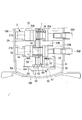
- FIG. 1 is a longitudinal sectional view of a hermetic compressor according to an embodiment of the present invention.
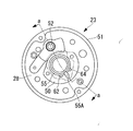
- FIG. 2 is an enlarged longitudinal sectional view of a main part of the hermetic compressor shown in FIG. 1. It is the top view which looked at the lower bearing of the hermetic compressor shown in Drawing 2 from the lower part.
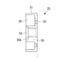
- FIG. 4 is a cross-sectional view corresponding to aa of the lower bearing shown in FIG. 3. It is a cross-sectional view of the oil supply pump part of the hermetic compressor shown in FIG.
- FIG. 1 is a longitudinal sectional view of a hermetic compressor 1 according to an embodiment of the present invention.
- a low-stage two-cylinder rotary compressor that constitutes the first compressor 2 is disposed in the lower portion of the hermetic housing 10, and a high-stage scroll compressor that constitutes the second compressor 3 in the upper portion.
- the hermetic compressor 1 according to the present invention will be described by taking a hermetic multistage compressor provided with an example as an example.
- the present invention is not limited to this, and the first compressor 2 is a single-cylinder rotary compressor.
- the second compressor 3 does not need to be a scroll compressor, and may be a compressor of another type.
- the hermetic compressor (sealed multistage compressor) 1 includes a hermetic housing 10.
- the sealed housing 10 includes a cylindrical center housing 10A, an annular bearing bracket 11 provided by welding all around the center housing 10A, a lower housing 10B that seals the lower portion of the center housing 10A, and the bearing bracket 11
- the upper housing 10C is provided at the upper portion by welding all around and seals the upper portion of the center housing 10A.
- An electric motor 4 including a stator 5 and a rotor 6 is fixedly installed at a substantially central portion in the center housing 10A.
- a rotating shaft (crankshaft) 7 is integrally coupled to the rotor 6.
- a low-stage two-cylinder rotary compressor 2 constituting the first compressor 2 is installed below the electric motor 4, a low-stage two-cylinder rotary compressor 2 constituting the first compressor 2 is installed.
- the two-cylinder rotary compressor 2 includes cylinder chambers 20A and 20B.
- the cylinder main bodies 21A and 21B are fixedly installed in the center housing 10A, and are fixedly installed on the upper part of the cylinder main body 21A and the lower part of the cylinder main body 21B.
- the two-cylinder rotary compressor 2 sucks a low-pressure refrigerant gas (working gas) into the cylinder chambers 20A and 20B via the suction pipes 26A and 26B, and this refrigerant gas is rotated by the rotors 25A and 25B to an intermediate pressure.
- refrigerant gas working gas
- This refrigerant gas is rotated by the rotors 25A and 25B to an intermediate pressure.
- This intermediate-pressure refrigerant gas flows through a gas passage hole (not shown) provided in the rotor 6 of the electric motor 4 and is guided to the upper space of the electric motor 4, and further the high-pressure refrigerant gas constituting the second compressor 3. It is sucked into the stage side scroll compressor 3 and compressed by two stages.
- the high-stage scroll compressor 3 constituting the second compressor 3 is provided in the upper housing 10C.
- the scroll compressor 3 is provided with a bearing 30 that supports a rotating shaft (crankshaft) 7, and a bearing case 31 (also referred to as a frame member or a supporting member) fixedly installed on the upper surface of the bearing bracket 11 via bolts 12.
- a bearing case 31 also referred to as a frame member or a supporting member
- the spiral wraps 32B and 33B standing on the end plates 32A and 33A, respectively, and the spiral wraps 32B and 33B are engaged with each other and assembled on the bearing case 31 to constitute a pair of compression chambers 34.
- a fixed scroll member 32 and an orbiting scroll member 33 are provided.
- the scroll compressor 3 further couples the orbiting scroll member 33 and the eccentric pin 7C of the rotating shaft 7 via the drive bush 13 to rotate the orbiting scroll member 33 so as to revolve and drive, and the orbiting scroll member 33.
- a rotation prevention mechanism 35 that is provided between the bearing case 31 and prevents the rotation of the orbiting scroll member 33 to rotate and revolves, and a discharge reed valve 36 that is provided on the back side of the fixed scroll member 32 and opens and closes the discharge port 32C.
- a fixed cover so as to surround the discharge reed valve 36 on the back side of the fixed scroll member 32, a discharge cover 38 forming an oil separation chamber 37, and a compressed high-pressure gas connected to the center of the discharge cover 38 Is installed in the oil separation chamber 37 and the discharge pipe 39 for discharging the oil to the outside, and the oil is centrifuged from the compressed gas.
- the oil separation mechanism 40 configured to include a.
- the scroll compressor 3 sucks the intermediate-pressure refrigerant gas compressed by the two-cylinder rotary compressor 2 and discharged into the sealed housing 10 into the compression chamber 34. After being compressed to a higher pressure state by a compression operation by revolving turning drive, it is configured to discharge to the oil separation chamber 37 in the discharge cover 38 via the discharge reed valve 36.
- the high-temperature and high-pressure refrigerant gas is sent to the outside of the hermetic compressor 1, that is, to the refrigeration cycle side through the discharge pipe 39 after the oil in the gas is separated by the oil separation mechanism 40 in the oil separation chamber 37. It has become so.
- a positive displacement oil pump 14 is incorporated between the lowermost end of the rotary shaft (crankshaft) 7 and the lower bearing 23 of the low-stage rotary compressor 2.
- the oil pump 14 pumps up the lubricating oil 15 filled in the bottom of the hermetic housing 10, and through the oil holes 16 provided in the rotary shaft 7, the bearing portions of the two-cylinder rotary compressor 2 and the scroll compressor 3.
- the lubricating oil 15 is forcibly supplied to a required lubricating portion.
- the oil supplied by the oil supply pump 14 and lubricated the scroll compressor 3 and the oil separated by the oil separation mechanism 40 are oil drop holes 41 and 42 provided in the fixed scroll member 32 and the bearing case 31, respectively. , 43, the oil is discharged from an oil discharge pipe 44 connected to the bearing bracket 11 to the bottom of the hermetic housing 10. It is assumed that a pressure reduction mechanism (not shown) is interposed in the oil drain hole 41 from the oil separation mechanism 40.
- the lower bearing 23, the lower muffler chamber 28, and the oil supply pump 14 described above are configured as follows.
- the lower bearing 23 is provided with a bearing boss portion 50 that supports the shaft end of the rotating shaft (crankshaft) 7 at the center portion, and surrounds the bearing boss portion 50 on the outer periphery thereof.
- it is set as the double cylinder shape provided with the outer cylinder 51 with the lower part opened.
- An annular space formed between the bearing boss portion 50 of the lower bearing 23 and the outer cylinder 51 is configured as a lower muffler chamber 28.
- the lower bearing 23 is provided with a discharge port 52 that allows the cylinder chamber 20B and the lower muffler chamber 28 to communicate with each other.
- the discharge port 52 includes a leaf spring-like reed valve on the lower muffler chamber 28 side.
- a discharge valve 53 is installed.
- the lower bearing 23 is fixedly installed on the cylinder body 21 ⁇ / b> B by a plurality of bolts 54.
- a cylinder chamber 55 having a predetermined dimension in the axial direction constituting the oil supply pump 14 is formed concentrically with the rotary shaft 7 on the lower end surface of the bearing boss portion 50.
- the cylinder chamber 54 is provided with a blade groove 55A extending in the radial direction.
- the lower end surface of the bearing boss portion 50 in the lower bearing 23 and the lower end surface of the outer cylinder 51 are formed on the same plane, and the lower end surface includes a thin plate member 56 and a thick plate presser member 57.
- a flat lid member 58 is fixedly installed via a bolt 59. As a result, the lower muffler chamber 28 and the cylinder chamber 55 are covered and sealed with a common flat lid member 58.
- the cylinder chamber 55 defined by the lid member 58 is attached to an eccentric portion 7 ⁇ / b> D provided at the shaft end of the rotating shaft 7.
- a rotor 60 that is rotated on the inner peripheral surface is accommodated.
- a blade 60A that is slidably fitted in a blade groove 55A of the cylinder chamber 55 is integrally provided on the outer periphery of the rotor 60, and partitions the inside of the cylinder chamber 55 into a suction side and a discharge side of the lubricating oil.
- a suction port 62 communicating with a suction pipe 61 suspended in the lubricant 15 filled in the bottom of the sealed housing 10 is opened on the lubricant suction side of the cylinder chamber 55, and the lubricant discharge side
- a discharge port 64 communicating with an oil supply hole 16 provided in the rotary shaft 7 is opened through an oil passage 63 provided in the lid member 58.
- an oil supply pump 14 for forcibly supplying the lubricating oil 15 to the two-cylinder rotary compressor 2 and the scroll compressor 3 is configured.
- the oil passage 63 is provided on the mating surface of the plate member 56 and the plate pressing member 57 constituting the lid member 58 so as to communicate with the discharge port 64 and the oil supply hole 16.
- the discharge port 52 provided in the lower bearing 23 and the suction port 62, the discharge port 64 and the blade groove 55 ⁇ / b> A constituting the oil supply pump 14 provided in the bearing boss 50 are opposite to each other across the axis of the rotating shaft 7. (See FIG. 3).
- the outer diameter of the bearing boss portion 50 is increased to provide the suction port 62, the discharge port 64, and the blade groove 55A, and the radial space between the outer cylinder 51 and the rotary shaft 7 is reduced.
- the space between the bearing boss 50 and the outer cylinder 51 on the side where the discharge port 52 on the opposite side is provided across the shaft core can be widened. For this reason, the installation space of the discharge valve 53 comprised by a reed valve can fully be ensured.
- the low-temperature and low-pressure refrigerant gas sucked into the cylinder chambers 20A and 20B of the two-cylinder rotary compressor 2 constituting the first compressor 2 through the suction pipes 26A and 26B reaches the intermediate pressure by the rotation of the rotors 25A and 25B. After being compressed, the air is discharged into the upper muffler chamber 27 and the lower muffler chamber 28, and the pulsation is attenuated.
- the intermediate pressure refrigerant gas is merged in the upper muffler chamber 27 and then discharged into the lower space of the electric motor 4, from which gas passage holes (not shown) provided in the rotor 6 of the electric motor 4, etc. And flows into the upper space of the electric motor 4.
- the intermediate-pressure refrigerant gas that has flowed into the upper space of the electric motor 4 passes through a suction gas passage (not shown) formed between the outer surface of the bearing case 31 and the upper surface of the bearing bracket 11 from the center region of the center housing 10A. Then, the air is sucked into the compression chamber 34 formed between the fixed scroll member 32 and the orbiting scroll member 33.
- the intermediate-pressure refrigerant gas is compressed into a high-temperature and high-pressure state by a compression operation caused by the orbiting scroll member 33 being driven to revolve orbit, and then discharged into the discharge cover 38 from the discharge port 32C via the discharge reed valve 36. It is.
- part of the lubricating oil 15 supplied by the oil supply pump 14 and used for lubrication of the two-cylinder rotary compressor 2 dissolves in the refrigerant gas, and enters the center housing 10A together with the intermediate-pressure refrigerant gas. Vomited. Further, the intermediate pressure refrigerant gas is supplied to the scroll compressor 3 through the oil supply hole 16, lubricates the scroll compressor 3, and then passes through the oil drain holes 43 and 42 and the oil discharge pipe 44 to enter the sealed housing 10. Part of the lubricating oil 15 that flows down to the bottom of the melted.
- the intermediate pressure refrigerant gas in which the lubricating oil 15 is dissolved in this way is sucked into the scroll compressor 3 while containing the oil and compressed, becomes high-temperature high-pressure gas, and is discharged from the discharge port 32C together with the oil.
- the high-temperature and high-pressure compressed gas containing oil is connected to the center of the discharge cover 38 after the oil is centrifuged by a centrifugal oil separation mechanism 40 provided in an oil separation chamber 37 in the discharge cover 38.
- the discharge pipe 39 is discharged to the refrigeration cycle side.
- OCR oil circulation rate
- the oil separated in the oil separation chamber 37 is depressurized to a low pressure in the oil dropping hole 41 by a pressure reducing mechanism, and then flows down to the bottom in the sealed housing 10 through the oil dropping hole 42 and the oil discharge pipe 44.
- the lower bearing 23 provided with the cylinder chamber 55 of the oil pump 14 for supplying the lubricating oil 15 is formed in a double cylinder shape, and the cylinder chamber 55 is provided on the lower end surface of the bearing boss portion 50 formed at the center portion thereof.
- An annular lower muffler chamber 28 is provided between the bearing boss portion 50 and an outer cylinder 51 formed so as to surround the outer periphery thereof.
- the lower muffler chamber 28 and the cylinder chamber 55 are defined by forming the lower end surfaces of the bearing boss portion 50 and the outer cylinder 51 on the same plane and covering the lower end surfaces with a common flat lid member 58. .
- both the lower muffler chamber 28 and the cylinder chamber 55 can be defined by the double-cylindrical lower bearing 23 and the flat lid member 58.
- the number of components of the lower muffler chamber 28 and the oil pump 14 can be reduced, and the configuration can be simplified and the cost can be reduced. Since it is possible to process the lower end surface of the bearing boss portion 50 and the outer cylinder 51 and the flat surface processing of the flat lid member 58 attached to the lower end surface in one step, the lower bearing 23 and the lid The number of processing steps for the member 58 (the plate member 56 and the plate pressing member 57) can be reduced, and the productivity can be improved and the cost can be reduced.
- the lower muffler chamber 28 can be simply configured by the outer cylinder 51 of the lower bearing 23 having a double cylinder shape, it is not necessary to install a lower muffler part as a separate part. it can. As a result, the effective volume of the lower muffler chamber 28 can be ensured to the maximum, and the effect of reducing discharge pulsation can be enhanced.
- the positive displacement oil pump 14 is configured to send the lubricating oil 15 to the oil hole 16 formed in the rotating shaft 7, the minimum components using the lower bearing 23 and the lower end of the rotating shaft 7 are used.
- the oil supply pump 14 to the second compressor (scroll compressor) 3 disposed in the upper part of the hermetic housing 10 can be configured.
- both the lower muffler chamber 28 and the positive displacement oil pump 14 can be configured simply and inexpensively with a minimum number of parts.
- the hermetic compressor 1 of the present invention is not limited to one using an HFC refrigerant such as R410A as a working gas, but can be similarly applied to one using a CO2 refrigerant or another refrigerant.
- the first compressor 2 disposed in the lower portion of the hermetic housing 10 may be a single-cylinder rotary compressor. Even in this case, providing the lower muffler chamber 28 in the lower bearing 23 is effective in reducing the pressure loss during discharge.
- the oil supply pump 14 not only the thing of the said embodiment but of course, you may use the positive displacement pump of another type.
Landscapes
- Engineering & Computer Science (AREA)
- Mechanical Engineering (AREA)
- General Engineering & Computer Science (AREA)
- Applications Or Details Of Rotary Compressors (AREA)
Abstract
An enclosed compressor having first and second compressors arranged at the upper and lower portions in an enclosed housing, with the first compressor at the lower part being a rotary compressor. The enclosed compressor is simplified in structure and reduced in cost by reducing the number of parts which construct an oil supply pump and a lower muffler chamber and adapting the parts to be easily worked. In an enclosed compressor (1) having first and second compressors (2, 3) arranged at the upper and lower portions in an enclosed housing (10) with the first compressor (2) at the lower portion being a rotary compressor, a lower bearing (23) of the rotary compressor (2) supports the lower end of a rotating shaft (7) on the center side of the lower bearing, has a bearing boss (50) having at the lower end surface thereof a cylinder chamber (55) of the oil supply pump (14), and is formed in a double-tube shape having an outer tube (51) located on the outer peripheral side of the bearing boss (50) so as to surround the bearing boss. A lid (58) is mounted to the lower end surface of the lower bearing (23) to define the cylinder chamber (55) and the lower muffler chamber (28) of the rotary compressor (2).
Description
本発明は、密閉ハウジング内の下部および上部にそれぞれ電動モータによって駆動される第1圧縮機および第2圧縮機が配設された密閉型圧縮機に関するものである。
The present invention relates to a hermetic compressor in which a first compressor and a second compressor driven by an electric motor are respectively disposed at a lower part and an upper part in a hermetic housing.
密閉ハウジング内の中央部位に電動モータを設置し、その下部および上部に電動モータに連結されたクランク軸を介して回転駆動される第1圧縮機および第2圧縮機を配設した構成の密閉型圧縮機としては、特許文献1に示すものが提案されている。この特許文献1に示された密閉型圧縮機は、電動モータの下部に第1圧縮機を構成する低段側ロータリ圧縮機、上部に第2圧縮機を構成する高段側スクロール圧縮機を配設した密閉型の多段圧縮機であり、低段側ロータリ圧縮機で圧縮した中間圧の冷媒ガスを密閉ハウジング内に吐き出し、この冷媒ガスを高段側スクロール圧縮機に吸入して高圧まで圧縮した後、圧縮機の外部へと送出するように構成されている。このように、密閉ハウジング内の上部に第2圧縮機を配設している密閉型圧縮機では、第2圧縮機の摺動部位を潤滑するために、クランク軸の下端部に給油ポンプを設け、この給油ポンプによって密閉ハウジングの底部に充填されている潤滑油を第2圧縮機に給油することが不可欠となる。
A sealed type having a configuration in which an electric motor is installed at a central portion in a hermetic housing, and a first compressor and a second compressor that are rotationally driven via a crankshaft connected to the electric motor are disposed below and above the motor. As a compressor, what is shown to patent document 1 is proposed. The hermetic compressor disclosed in Patent Document 1 is provided with a low-stage rotary compressor constituting the first compressor at the lower part of the electric motor and a high-stage scroll compressor constituting the second compressor at the upper part. This is a hermetic multistage compressor installed. The intermediate-pressure refrigerant gas compressed by the low-stage rotary compressor is discharged into the hermetic housing, and this refrigerant gas is sucked into the high-stage scroll compressor and compressed to a high pressure. Then, it is comprised so that it may send out the exterior of a compressor. Thus, in the hermetic compressor in which the second compressor is disposed in the upper part of the hermetic housing, an oil supply pump is provided at the lower end of the crankshaft in order to lubricate the sliding portion of the second compressor. It is indispensable to supply the second compressor with the lubricating oil filled in the bottom of the hermetic housing by the oil pump.
一方、密閉ハウジングの下部にロータリ圧縮機を配設して構成された密閉型圧縮機において、下部軸受側に下部マフラ室を設けたものが多数提案されている。下部軸受側に下部マフラ室を設けた密閉型圧縮機としては、特許文献2,3に示されているように、2気筒ロータリ圧縮機(ツインロータリとも云う。)が多い。しかし、これに限らずに、単気筒ロータリ圧縮機にあって、吐出時の圧損を低減することを目的に上下の軸受にそれぞれマフラ室を設け、上下2箇所から圧縮ガスを吐出するように構成としたものが知られている。
On the other hand, many sealed compressors configured by disposing a rotary compressor at the lower part of a hermetic housing and having a lower muffler chamber on the lower bearing side have been proposed. As hermetic compressors having a lower muffler chamber on the lower bearing side, there are many two-cylinder rotary compressors (also referred to as twin rotary) as disclosed in Patent Documents 2 and 3. However, the present invention is not limited to this, and in a single cylinder rotary compressor, a muffler chamber is provided in each of the upper and lower bearings for the purpose of reducing pressure loss at the time of discharge, and the compressed gas is discharged from the upper and lower portions. Is known.
しかしながら、密閉ハウジング内の下部および上部にそれぞれ第1圧縮機および第2圧縮機を配設した密閉型圧縮機において、下部に配設される第1圧縮機がロータリ圧縮機とされたものでは、下部軸受の周りに吐出弁および下部マフラ室と、第2圧縮機への給油ポンプとを設けた場合に、下部軸受周りの構成が複雑化するとともに、加工工数、組み立て工数の増加およびコストアップは避けられなかった。また、下部軸受に対して下部マフラ室の構成部材を取り付ける取り付け代の確保が必要となることから、その分下部マフラ室の容積が小さくなり、吐出マフラの機能が低下してしまうという問題を有している。
However, in the hermetic compressor in which the first compressor and the second compressor are respectively disposed in the lower and upper portions in the hermetic housing, the first compressor disposed in the lower portion is a rotary compressor. When a discharge valve and a lower muffler chamber and an oil pump for the second compressor are provided around the lower bearing, the configuration around the lower bearing becomes complicated, and the processing man-hours, assembly man-hours and cost increase are It was inevitable. In addition, since it is necessary to secure a mounting allowance for attaching the components of the lower muffler chamber to the lower bearing, there is a problem that the volume of the lower muffler chamber is correspondingly reduced and the function of the discharge muffler is reduced. is doing.
本発明は、このような事情に鑑みてなされたものであって、密閉ハウジング内の下部および上部にそれぞれ第1および第2圧縮機が配設され、下部の第1圧縮機がロータリ圧縮機とされた密閉型圧縮機において、給油ポンプおよび下部マフラ室を構成する部品点数の削減と部品加工の容易化を図り、構成のシンプル化およびコストダウンを実現することができる密閉型圧縮機を提供することを目的とする。
The present invention has been made in view of such circumstances, and first and second compressors are respectively disposed at a lower portion and an upper portion in a hermetic housing, and the lower first compressor is a rotary compressor. Provided is a hermetic compressor capable of reducing the number of parts constituting the oil pump and the lower muffler chamber and facilitating parts processing, simplifying the construction and reducing costs. For the purpose.
上記課題を解決するために、本発明の密閉型圧縮機は、以下の手段を採用する。
すなわち、本発明の一態様にかかる密閉型圧縮機は、密閉ハウジング内の下部および上部に配設された第1および第2圧縮機と、該第1および第2圧縮機間に配設された電動モータと、該電動モータにより駆動され、両端部がそれぞれ前記第1および第2圧縮機に連結された回転軸と、該回転軸の下端部に設けられ、前記第2圧縮機に密閉ハウジング内に充填された潤滑油を給油する給油ポンプとを備え、前記第1圧縮機がロータリ圧縮機により構成された密閉型圧縮機において、前記ロータリ圧縮機の下部軸受が、中心側に前記回転軸の下端部を支持し、下端面に前記給油ポンプのシリンダ室が設けられた軸受ボス部を備え、その外周側に前記軸受ボス部を包囲する外筒を備えた二重筒型形状とされるとともに、前記下部軸受の下端面に蓋部材を装着することにより前記シリンダ室と前記ロータリ圧縮機の下部マフラ室とが区画形成されている。 In order to solve the above problems, the hermetic compressor of the present invention employs the following means.
That is, the hermetic compressor according to one aspect of the present invention is disposed between the first and second compressors disposed at the lower and upper portions in the hermetic housing, and the first and second compressors. An electric motor, a rotary shaft driven by the electric motor and having both ends connected to the first and second compressors, and a lower end portion of the rotary shaft; A hermetic pump in which the first compressor is constituted by a rotary compressor, and the lower bearing of the rotary compressor is arranged on the center side of the rotary shaft. While having a bearing boss portion that supports the lower end portion and has a cylinder chamber of the oil supply pump provided on the lower end surface, and has an outer cylinder that surrounds the bearing boss portion on the outer peripheral side thereof, a double cylinder shape is provided. A lid on the lower end surface of the lower bearing A lower muffler chamber of the rotary compressor and the cylinder chamber is partitioned and formed by mounting the wood.
上記態様によれば、下部軸受が回転軸の下端部を支持し、下端面に給油ポンプのシリンダ室が設けられた軸受ボス部と、その外周を包囲する外筒とを備えた二重筒型形状とされるとともに、この下部軸受の下端面に蓋部材を装着することによりシリンダ室と下部マフラ室とが区画形成されている。このため、二重筒型形状とした下部軸受を利用して給油ポンプのシリンダ室とロータリ圧縮機の下部マフラ室の双方を区画形成することができる。これによって、部品点数の削減と部品加工の容易化を図り、構成のシンプル化およびコストダウンを実現することができる。また、下部マフラ室を二重筒型形状とされた下部軸受の外筒によりシンプルに構成することができるため、下部マフラ室の取り付け代を不要としてその有効容積を最大限確保することができる。
According to the above aspect, the double bearing type is provided with the bearing boss portion in which the lower bearing supports the lower end portion of the rotating shaft, the cylinder chamber of the oil supply pump is provided on the lower end surface, and the outer cylinder surrounding the outer periphery thereof. The cylinder chamber and the lower muffler chamber are partitioned and formed by attaching a lid member to the lower end surface of the lower bearing. For this reason, both the cylinder chamber of the oil pump and the lower muffler chamber of the rotary compressor can be partitioned by using a lower cylindrical bearing. As a result, the number of parts can be reduced and parts processing can be facilitated, and the configuration can be simplified and the cost can be reduced. In addition, since the lower muffler chamber can be simply configured by the outer cylinder of the lower bearing having a double cylinder shape, the effective volume can be ensured to the maximum without the need for mounting the lower muffler chamber.
本発明の一態様に係る密閉型圧縮機は、上記の密閉型圧縮機において、前記軸受ボス部の下端面と前記外筒の下端面とを同一平面上に形成し、該下端面を平板状の前記蓋部材により蓋って前記シリンダ室および前記下部マフラ室を区画形成している。
A hermetic compressor according to one aspect of the present invention is the above-described hermetic compressor, wherein the lower end surface of the bearing boss portion and the lower end surface of the outer cylinder are formed on the same plane, and the lower end surface is flat. The cylinder chamber and the lower muffler chamber are partitioned by the lid member.
上記態様によれば、軸受ボス部の下端面と外筒の下端面とを同一平面上に形成し、その下端面を平板状の蓋部材により蓋ってシリンダ室および下部マフラ室を区画形成している。したがって、軸受ボス部および外筒の下端面の加工、ならびに下端面に装着される平板状の蓋部材の平面加工をそれぞれ一工程で加工することが可能となる。このため、下部軸受および蓋部材の加工工数を低減し、生産性の向上およびコストダウンを図ることができる。
According to the above aspect, the lower end surface of the bearing boss part and the lower end surface of the outer cylinder are formed on the same plane, and the lower end surface is covered with the flat lid member to form the cylinder chamber and the lower muffler chamber. ing. Therefore, it is possible to process the lower end surface of the bearing boss portion and the outer cylinder and the flat surface processing of the flat lid member attached to the lower end surface in one step. For this reason, the processing man-hour of a lower bearing and a cover member can be reduced, and improvement of productivity and cost reduction can be aimed at.
本発明のの一態様に係る密閉型圧縮機は、上述のいずれかの密閉型圧縮機において、前記給油ポンプを、前記回転軸の下端部に装着され、前記シリンダ室内で回動されるロータと、前記シリンダ室に連通される吸入口および吐出口とを備え、前記潤滑油を前記回転軸に穿設されている給油孔に送出する容積形ポンプにより構成されている。
The hermetic compressor according to one aspect of the present invention is the hermetic compressor according to any one of the above-described hermetic compressors, wherein the oil supply pump is attached to a lower end portion of the rotating shaft and is rotated in the cylinder chamber. And a positive displacement pump that includes a suction port and a discharge port that communicate with the cylinder chamber, and that feeds the lubricating oil to an oil supply hole formed in the rotating shaft.
上記態様によれば、給油ポンプを、回転軸の下端部に装着され、シリンダ室内で回動されるロータと、そのシリンダ室に連通される吸入口および吐出口とを備え、潤滑油を回転軸に穿設されている給油孔に送出する容積形ポンプにより構成している。このため、下部軸受および回転軸の下端部を利用して最小限の構成部品により、第2圧縮機に潤滑油を給油する容積形の給油ポンプを設けることができる。従って、下部マフラ室および容積形の給油ポンプを共に最小限の部品点数でシンプルにかつ安価に構成することができる。
According to the above aspect, the oil supply pump is mounted on the lower end portion of the rotating shaft and includes the rotor rotated in the cylinder chamber, the suction port and the discharge port communicating with the cylinder chamber, and the lubricating oil is supplied to the rotating shaft. It is comprised with the positive displacement pump which sends out to the oil supply hole drilled in. For this reason, a positive displacement oil supply pump for supplying lubricating oil to the second compressor can be provided by using the lower bearing and the lower end portion of the rotating shaft with a minimum number of components. Therefore, both the lower muffler chamber and the positive displacement oil pump can be configured simply and inexpensively with a minimum number of parts.
本発明の一態様に係る密閉型圧縮機は、上記の密閉型圧縮機において、前記下部マフラ室に圧縮ガスを吐き出す吐出ポートおよび吐出弁を、前記回転軸の軸芯を挟んで前記給油ポンプの前記吸入口および前記吐出口とは反対側に配設している。
A hermetic compressor according to one aspect of the present invention is the above-described hermetic compressor, wherein a discharge port and a discharge valve that discharge compressed gas to the lower muffler chamber are disposed between the oil pump and the shaft of the rotary shaft. The suction port and the discharge port are disposed on the opposite side.
上記態様によれば、下部マフラ室に圧縮ガスを吐き出す吐出ポートおよび吐出弁を、回転軸の軸芯を挟んで給油ポンプの吸入口および吐出口とは反対側に配設している。したがって、下部マフラ室内の吐出ポートおよび吐出弁が配設される側のスペースを、給油ポンプの吸入口および吐出口が配設される側のスペースよりも広くすることができる。このため、一般に細長いリード弁が使用される吐出弁を設置し易くすることができ、下部軸受を大きくすることなく、コンパクト化したまま給油ポンプおよび吐出弁を収容設置することができる。
According to the above aspect, the discharge port and the discharge valve for discharging the compressed gas to the lower muffler chamber are arranged on the opposite side to the suction port and the discharge port of the oil supply pump with the axis of the rotating shaft interposed therebetween. Therefore, the space on the side where the discharge port and the discharge valve are disposed in the lower muffler chamber can be made wider than the space on the side where the suction port and the discharge port of the oil supply pump are disposed. For this reason, it is possible to easily install a discharge valve in which an elongated reed valve is generally used, and the oil supply pump and the discharge valve can be accommodated and installed without increasing the size of the lower bearing.
本発明によると、二重筒型形状とした下部軸受を用いることにより給油ポンプのシリンダ室とロータリ圧縮機の下部マフラ室の双方を区画形成することができる。このため、部品点数の削減と部品加工の容易化を図り、構成のシンプル化およびコストダウンを実現することができる。下部マフラ室を二重筒型形状とされた下部軸受の外筒によりシンプルに構成することができるため、下部マフラ室の取り付け代を不要としてその有効容積を最大限確保することができる。
According to the present invention, both the cylinder chamber of the oil supply pump and the lower muffler chamber of the rotary compressor can be defined by using the lower cylindrical bearing. For this reason, the number of parts can be reduced and the parts can be easily processed, and the configuration can be simplified and the cost can be reduced. Since the lower muffler chamber can be simply configured by the outer cylinder of the lower bearing having a double cylinder shape, the effective volume can be secured to the maximum without the need for the mounting cost of the lower muffler chamber.
1 密閉型圧縮機
2 第1圧縮機(2気筒ロータリ圧縮機)
3 第2圧縮機(スクロール圧縮機)
4 電動モータ
7 回転軸(クランク軸)
10 密閉ハウジング
14 給油ポンプ
16 給油孔
23 下部軸受
28 下部マフラ室
50 軸受ボス部
51 外筒
52 吐出ポート
53 吐出弁
55 シリンダ室
58 蓋部材
60 ロータ
62 吸入口
64 吐出口 1hermetic compressor 2 first compressor (2-cylinder rotary compressor)
3 Second compressor (scroll compressor)
4Electric motor 7 Rotating shaft (Crank shaft)
DESCRIPTION OFSYMBOLS 10 Sealing housing 14 Oil supply pump 16 Oil supply hole 23 Lower bearing 28 Lower muffler chamber 50 Bearing boss part 51 Outer cylinder 52 Discharge port 53 Discharge valve 55 Cylinder chamber 58 Lid member 60 Rotor 62 Intake port 64 Discharge port
2 第1圧縮機(2気筒ロータリ圧縮機)
3 第2圧縮機(スクロール圧縮機)
4 電動モータ
7 回転軸(クランク軸)
10 密閉ハウジング
14 給油ポンプ
16 給油孔
23 下部軸受
28 下部マフラ室
50 軸受ボス部
51 外筒
52 吐出ポート
53 吐出弁
55 シリンダ室
58 蓋部材
60 ロータ
62 吸入口
64 吐出口 1
3 Second compressor (scroll compressor)
4
DESCRIPTION OF
以下に、本発明にかかる一実施形態について、図1ないし図5を参照して説明する。
図1には、本発明の一実施形態に係る密閉型圧縮機1の縦断面図が示されている。本実施形態では、便宜上、密閉ハウジング10の下部に第1圧縮機2を構成する低段側2気筒ロータリ圧縮機を配設し、上部に第2圧縮機3を構成する高段側スクロール圧縮機を配設した密閉型多段圧縮機を例に本発明の密閉型圧縮機1について説明するが、本発明は、これに限られるものではなく、第1圧縮機2が単気筒ロータリ圧縮機であってもよく、さらに第2圧縮機3はスクロール圧縮機である必要はなく、他形式の圧縮機であってもよい。 An embodiment according to the present invention will be described below with reference to FIGS. 1 to 5.
FIG. 1 is a longitudinal sectional view of a hermetic compressor 1 according to an embodiment of the present invention. In the present embodiment, for convenience, a low-stage two-cylinder rotary compressor that constitutes thefirst compressor 2 is disposed in the lower portion of the hermetic housing 10, and a high-stage scroll compressor that constitutes the second compressor 3 in the upper portion. The hermetic compressor 1 according to the present invention will be described by taking a hermetic multistage compressor provided with an example as an example. However, the present invention is not limited to this, and the first compressor 2 is a single-cylinder rotary compressor. Further, the second compressor 3 does not need to be a scroll compressor, and may be a compressor of another type.
図1には、本発明の一実施形態に係る密閉型圧縮機1の縦断面図が示されている。本実施形態では、便宜上、密閉ハウジング10の下部に第1圧縮機2を構成する低段側2気筒ロータリ圧縮機を配設し、上部に第2圧縮機3を構成する高段側スクロール圧縮機を配設した密閉型多段圧縮機を例に本発明の密閉型圧縮機1について説明するが、本発明は、これに限られるものではなく、第1圧縮機2が単気筒ロータリ圧縮機であってもよく、さらに第2圧縮機3はスクロール圧縮機である必要はなく、他形式の圧縮機であってもよい。 An embodiment according to the present invention will be described below with reference to FIGS. 1 to 5.
FIG. 1 is a longitudinal sectional view of a hermetic compressor 1 according to an embodiment of the present invention. In the present embodiment, for convenience, a low-stage two-cylinder rotary compressor that constitutes the
密閉型圧縮機(密閉型多段圧縮機)1は、密閉ハウジング10を備えている。密閉ハウジング10は、円筒状のセンターハウジング10Aと、センターハウジング10Aの上部に全周溶接により設けられた環状のベアリングブラケット11と、センターハウジング10Aの下部を密閉する下部ハウジング10Bと、ベアリングブラケット11の上部に全周溶接により設けられ、センターハウジング10Aの上部を密閉する上部ハウジング10Cとから構成されている。
The hermetic compressor (sealed multistage compressor) 1 includes a hermetic housing 10. The sealed housing 10 includes a cylindrical center housing 10A, an annular bearing bracket 11 provided by welding all around the center housing 10A, a lower housing 10B that seals the lower portion of the center housing 10A, and the bearing bracket 11 The upper housing 10C is provided at the upper portion by welding all around and seals the upper portion of the center housing 10A.
センターハウジング10A内の略中央部には、ステータ5とロータ6とから構成される電動モータ4が固定設置されている。ロータ6には、回転軸(クランク軸)7が一体に結合されている。この電動モータ4の下部には、第1圧縮機2を構成する低段側2気筒ロータリ圧縮機2が設置されている。この2気筒ロータリ圧縮機2は、シリンダ室20A,20Bを備え、センターハウジング10A内に固定設置されるシリンダ本体21A,21Bと、シリンダ本体21Aの上部およびシリンダ本体21Bの下部に固定設置され、シリンダ室20Aの上部およびシリンダ室20Bの下部を密閉する上部軸受22および下部軸受23と、シリンダ本体21Aとシリンダ本体21Bとの間に介在された中間仕切り板24と、回転軸7のクランク部7A,7Bに嵌合され、シリンダ室20A,20Bの内周面を回動するロータ25A,25Bと、シリンダ室20A,20B内を吸入側と吐出側とに仕切る図示省略のブレードおよびブレード押えバネ等とを備えた構成とされている。
An electric motor 4 including a stator 5 and a rotor 6 is fixedly installed at a substantially central portion in the center housing 10A. A rotating shaft (crankshaft) 7 is integrally coupled to the rotor 6. Below the electric motor 4, a low-stage two-cylinder rotary compressor 2 constituting the first compressor 2 is installed. The two-cylinder rotary compressor 2 includes cylinder chambers 20A and 20B. The cylinder main bodies 21A and 21B are fixedly installed in the center housing 10A, and are fixedly installed on the upper part of the cylinder main body 21A and the lower part of the cylinder main body 21B. An upper bearing 22 and a lower bearing 23 for sealing the upper portion of the chamber 20A and the lower portion of the cylinder chamber 20B, an intermediate partition plate 24 interposed between the cylinder body 21A and the cylinder body 21B, the crank portion 7A of the rotary shaft 7, 7B, rotors 25A and 25B that rotate on the inner peripheral surfaces of the cylinder chambers 20A and 20B, blades and blade pressing springs (not shown) that partition the cylinder chambers 20A and 20B into a suction side and a discharge side It is set as the structure provided with.
上記2気筒ロータリ圧縮機2は、吸入管26A,26Bを介してシリンダ室20A,20B内に低圧の冷媒ガス(作動ガス)を吸入し、この冷媒ガスをロータ25A,25Bの回動により中間圧まで圧縮した後、上部軸受22および下部軸受23を利用して上下に形成されている上部マフラ室27および下部マフラ室28内に吐出し、上部マフラ室27内で合流した後、センターハウジング10A内に吐き出すように構成されている。この中間圧冷媒ガスは、電動モータ4のロータ6に設けられているガス通路孔(図示省略)等を流通して電動モータ4の上部空間に導かれ、さらに第2圧縮機3を構成する高段側スクロール圧縮機3へと吸入されて2段圧縮されるようになっている。
The two-cylinder rotary compressor 2 sucks a low-pressure refrigerant gas (working gas) into the cylinder chambers 20A and 20B via the suction pipes 26A and 26B, and this refrigerant gas is rotated by the rotors 25A and 25B to an intermediate pressure. Are compressed into the upper muffler chamber 27 and the lower muffler chamber 28 that are formed vertically using the upper bearing 22 and the lower bearing 23, merge in the upper muffler chamber 27, and then in the center housing 10A. It is configured to exhale. This intermediate-pressure refrigerant gas flows through a gas passage hole (not shown) provided in the rotor 6 of the electric motor 4 and is guided to the upper space of the electric motor 4, and further the high-pressure refrigerant gas constituting the second compressor 3. It is sucked into the stage side scroll compressor 3 and compressed by two stages.
第2圧縮機3を構成する高段側スクロール圧縮機3は、上部ハウジング10C内に設けられている。スクロール圧縮機3は、回転軸(クランク軸)7を支持する軸受30が設けられ、ベアリングブラケット11の上面にボルト12を介して固定設置されるベアリングケース31(フレーム部材または支持部材とも云う。)と、それぞれ端板32A,33A上に立設される渦巻き状ラップ32B,33Bを備え、渦巻き状ラップ32B,33B同士を噛み合わせてベアリングケース31上に組み付けることにより一対の圧縮室34を構成する固定スクロール部材32および旋回スクロール部材33とを備えている。
The high-stage scroll compressor 3 constituting the second compressor 3 is provided in the upper housing 10C. The scroll compressor 3 is provided with a bearing 30 that supports a rotating shaft (crankshaft) 7, and a bearing case 31 (also referred to as a frame member or a supporting member) fixedly installed on the upper surface of the bearing bracket 11 via bolts 12. And the spiral wraps 32B and 33B standing on the end plates 32A and 33A, respectively, and the spiral wraps 32B and 33B are engaged with each other and assembled on the bearing case 31 to constitute a pair of compression chambers 34. A fixed scroll member 32 and an orbiting scroll member 33 are provided.
スクロール圧縮機3は、さらに旋回スクロール部材33と回転軸7の偏心ピン7Cとをドライブブッシュ13を介して結合し、旋回スクロール部材33を公転旋回駆動する旋回ボス部33Cと、旋回スクロール部材33とベアリングケース31との間に設けられ、旋回スクロール部材33を自転を阻止して公転旋回させる自転阻止機構35と、固定スクロール部材32の背面側に設けられ、吐出ポート32Cを開閉する吐出リード弁36と、固定スクロール部材32の背面側に吐出リード弁36を包囲するように固定設置され、油分離室37を形成するディスチャージカバー38と、ディスチャージカバー38の中心部に接続され、圧縮された高圧ガスを外部に吐き出す吐出管39と、油分離室37内に設置され、圧縮ガスから油を遠心分離する油分離機構40とを備えた構成とされている。
The scroll compressor 3 further couples the orbiting scroll member 33 and the eccentric pin 7C of the rotating shaft 7 via the drive bush 13 to rotate the orbiting scroll member 33 so as to revolve and drive, and the orbiting scroll member 33. A rotation prevention mechanism 35 that is provided between the bearing case 31 and prevents the rotation of the orbiting scroll member 33 to rotate and revolves, and a discharge reed valve 36 that is provided on the back side of the fixed scroll member 32 and opens and closes the discharge port 32C. A fixed cover so as to surround the discharge reed valve 36 on the back side of the fixed scroll member 32, a discharge cover 38 forming an oil separation chamber 37, and a compressed high-pressure gas connected to the center of the discharge cover 38 Is installed in the oil separation chamber 37 and the discharge pipe 39 for discharging the oil to the outside, and the oil is centrifuged from the compressed gas. Is the oil separation mechanism 40 configured to include a.
上記のスクロール圧縮機3は、2気筒ロータリ圧縮機2により圧縮されて密閉ハウジング10に吐き出された中間圧の冷媒ガスを圧縮室34内に吸入し、この中間圧冷媒ガスを旋回スクロール部材33の公転旋回駆動による圧縮動作によって更に高圧状態に圧縮した後、吐出リード弁36を介してディスチャージカバー38内の油分離室37に吐き出すように構成されている。この高温高圧冷媒ガスは、油分離室37内で油分離機構40によりガス中の油が分離された後、吐出管39を介して密閉型圧縮機1の外部、すなわち冷凍サイクル側へと送出されるようになっている。
The scroll compressor 3 sucks the intermediate-pressure refrigerant gas compressed by the two-cylinder rotary compressor 2 and discharged into the sealed housing 10 into the compression chamber 34. After being compressed to a higher pressure state by a compression operation by revolving turning drive, it is configured to discharge to the oil separation chamber 37 in the discharge cover 38 via the discharge reed valve 36. The high-temperature and high-pressure refrigerant gas is sent to the outside of the hermetic compressor 1, that is, to the refrigeration cycle side through the discharge pipe 39 after the oil in the gas is separated by the oil separation mechanism 40 in the oil separation chamber 37. It has become so.
回転軸(クランク軸)7の最下端部と低段側ロータリ圧縮機2の下部軸受23との間には、容積形の給油ポンプ14が組み込まれている。この給油ポンプ14は、密閉ハウジング10の底部に充填されている潤滑油15を汲み上げ、回転軸7内に設けられている給油孔16を経て2気筒ロータリ圧縮機2およびスクロール圧縮機3の軸受部等の所要潤滑箇所に潤滑油15を強制給油するように構成されている。
A positive displacement oil pump 14 is incorporated between the lowermost end of the rotary shaft (crankshaft) 7 and the lower bearing 23 of the low-stage rotary compressor 2. The oil pump 14 pumps up the lubricating oil 15 filled in the bottom of the hermetic housing 10, and through the oil holes 16 provided in the rotary shaft 7, the bearing portions of the two-cylinder rotary compressor 2 and the scroll compressor 3. For example, the lubricating oil 15 is forcibly supplied to a required lubricating portion.
給油ポンプ14により給油され、スクロール圧縮機3を潤滑した油、および上記の油分離機構40によって分離された油は、それぞれ固定スクロール部材32およびベアリングケース31に設けられている油落し孔41,42,43を経てベアリングブラケット11に接続されている油排出パイプ44から密閉ハウジング10の底部へと流下されるようになっている。なお、油分離機構40からの油落し孔41には、図示省略の減圧機構が介装されているものとする。
The oil supplied by the oil supply pump 14 and lubricated the scroll compressor 3 and the oil separated by the oil separation mechanism 40 are oil drop holes 41 and 42 provided in the fixed scroll member 32 and the bearing case 31, respectively. , 43, the oil is discharged from an oil discharge pipe 44 connected to the bearing bracket 11 to the bottom of the hermetic housing 10. It is assumed that a pressure reduction mechanism (not shown) is interposed in the oil drain hole 41 from the oil separation mechanism 40.
本実施形態では、上記した下部軸受23、下部マフラ室28および給油ポンプ14が以下のとおり構成されている。
下部軸受23は、図2ないし図4に示されるように、中心部位に回転軸(クランク軸)7の軸端を支持する軸受ボス部50が設けられ、その外周に軸受ボス部50を包囲するように下方が開放されている外筒51が設けられた二重筒型形状とされている。この下部軸受23の軸受ボス部50と外筒51との間に形成される環状の空間が下部マフラ室28とされるように構成されている。 In the present embodiment, thelower bearing 23, the lower muffler chamber 28, and the oil supply pump 14 described above are configured as follows.
As shown in FIGS. 2 to 4, thelower bearing 23 is provided with a bearing boss portion 50 that supports the shaft end of the rotating shaft (crankshaft) 7 at the center portion, and surrounds the bearing boss portion 50 on the outer periphery thereof. Thus, it is set as the double cylinder shape provided with the outer cylinder 51 with the lower part opened. An annular space formed between the bearing boss portion 50 of the lower bearing 23 and the outer cylinder 51 is configured as a lower muffler chamber 28.
下部軸受23は、図2ないし図4に示されるように、中心部位に回転軸(クランク軸)7の軸端を支持する軸受ボス部50が設けられ、その外周に軸受ボス部50を包囲するように下方が開放されている外筒51が設けられた二重筒型形状とされている。この下部軸受23の軸受ボス部50と外筒51との間に形成される環状の空間が下部マフラ室28とされるように構成されている。 In the present embodiment, the
As shown in FIGS. 2 to 4, the
下部軸受23には、シリンダ室20Bと下部マフラ室28とを連通する吐出ポート52が穿設されており、この吐出ポート52の下部マフラ室28側には、板バネ状のリード弁により構成される吐出弁53が設置されている。下部軸受23は、複数本のボルト54によってシリンダ本体21Bに固定設置されるようになっている。軸受ボス部50の下端面には、給油ポンプ14を構成する軸方向に所定寸法を有するシリンダ室55が回転軸7と同心円状に形成されている。シリンダ室54には、放射方向に延伸するブレード溝55Aが設けられている。
The lower bearing 23 is provided with a discharge port 52 that allows the cylinder chamber 20B and the lower muffler chamber 28 to communicate with each other. The discharge port 52 includes a leaf spring-like reed valve on the lower muffler chamber 28 side. A discharge valve 53 is installed. The lower bearing 23 is fixedly installed on the cylinder body 21 </ b> B by a plurality of bolts 54. A cylinder chamber 55 having a predetermined dimension in the axial direction constituting the oil supply pump 14 is formed concentrically with the rotary shaft 7 on the lower end surface of the bearing boss portion 50. The cylinder chamber 54 is provided with a blade groove 55A extending in the radial direction.
下部軸受23における軸受ボス部50の下端面と外筒51の下端面とは、同一平面上に形成されており、その下端面に薄いプレート部材56と板厚の厚いプレート押え部材57とからなる平板状の蓋部材58がボルト59を介して固定設置されている。これによって下部マフラ室28とシリンダ室55とが共通の平板状蓋部材58により蓋われて密閉された構成とされている。
The lower end surface of the bearing boss portion 50 in the lower bearing 23 and the lower end surface of the outer cylinder 51 are formed on the same plane, and the lower end surface includes a thin plate member 56 and a thick plate presser member 57. A flat lid member 58 is fixedly installed via a bolt 59. As a result, the lower muffler chamber 28 and the cylinder chamber 55 are covered and sealed with a common flat lid member 58.
蓋部材58により区画形成されたシリンダ室55内には、図5に示されるように、回転軸7の軸端に設けられた偏心部7Dに装着され、回転軸7の回転に伴いシリンダ室55の内周面を回動されるロータ60が収容されている。ロータ60の外周には、シリンダ室55のブレード溝55Aに摺動自在に嵌合されるブレード60Aが一体に設けられ、シリンダ室55内を潤滑油の吸い込み側と吐き出し側とに仕切っている。このシリンダ室55の潤滑油吸い込み側には、密閉ハウジング10の底部に充填された潤滑油15中に垂下される吸入パイプ61に連通されている吸入口62が開口されるとともに、潤滑油吐き出し側には、蓋部材58に設けられている油路63を介して回転軸7中に設けられている給油孔16に連通される吐出口64が開口されている。
As shown in FIG. 5, the cylinder chamber 55 defined by the lid member 58 is attached to an eccentric portion 7 </ b> D provided at the shaft end of the rotating shaft 7. A rotor 60 that is rotated on the inner peripheral surface is accommodated. A blade 60A that is slidably fitted in a blade groove 55A of the cylinder chamber 55 is integrally provided on the outer periphery of the rotor 60, and partitions the inside of the cylinder chamber 55 into a suction side and a discharge side of the lubricating oil. A suction port 62 communicating with a suction pipe 61 suspended in the lubricant 15 filled in the bottom of the sealed housing 10 is opened on the lubricant suction side of the cylinder chamber 55, and the lubricant discharge side A discharge port 64 communicating with an oil supply hole 16 provided in the rotary shaft 7 is opened through an oil passage 63 provided in the lid member 58.
これによって、2気筒ロータリ圧縮機2およびスクロール圧縮機3に潤滑油15を強制給油する給油ポンプ14が構成されている。なお、油路63は、蓋部材58を構成するプレート部材56とプレート押え部材57との合わせ面に吐出口64および給油孔16と連通するように設けられている。下部軸受23に設けられる吐出ポート52と、軸受ボス部50に設けられる給油ポンプ14を構成する吸入口62、吐出口64およびブレード溝55Aとは、回転軸7の軸芯を挟んで互いに反対側に配設されている(図3参照)。つまり、吸入口62、吐出口64およびブレード溝55Aを設けるために軸受ボス部50の外径が大きくなり、外筒51との間の放射方向スペースが狭くなるのに対して、回転軸7の軸芯を挟んで反対側の吐出ポート52を設ける側の軸受ボス部50と外筒51との間のスペースを広くすることができる。このため、リード弁により構成される吐出弁53の設置スペースを十分に確保することができる。
Thus, an oil supply pump 14 for forcibly supplying the lubricating oil 15 to the two-cylinder rotary compressor 2 and the scroll compressor 3 is configured. The oil passage 63 is provided on the mating surface of the plate member 56 and the plate pressing member 57 constituting the lid member 58 so as to communicate with the discharge port 64 and the oil supply hole 16. The discharge port 52 provided in the lower bearing 23 and the suction port 62, the discharge port 64 and the blade groove 55 </ b> A constituting the oil supply pump 14 provided in the bearing boss 50 are opposite to each other across the axis of the rotating shaft 7. (See FIG. 3). That is, the outer diameter of the bearing boss portion 50 is increased to provide the suction port 62, the discharge port 64, and the blade groove 55A, and the radial space between the outer cylinder 51 and the rotary shaft 7 is reduced. The space between the bearing boss 50 and the outer cylinder 51 on the side where the discharge port 52 on the opposite side is provided across the shaft core can be widened. For this reason, the installation space of the discharge valve 53 comprised by a reed valve can fully be ensured.
以上に説明の構成により、本実施形態によれば、以下の作用効果を奏する。
吸入管26A,26Bを介して第1圧縮機2を構成する2気筒ロータリ圧縮機2のシリンダ室20A,20Bに吸入された低温低圧の冷媒ガスは、ロータ25A,25Bの回動により中間圧まで圧縮された後、上部マフラ室27および下部マフラ室28内に吐き出され、脈動が減衰される。この中間圧冷媒ガスは、上部マフラ室27内で合流された後、電動モータ4の下部空間内に吐き出され、そこから電動モータ4のロータ6に設けられているガス通路孔(図示省略)等を流通して電動モータ4の上部空間に流動される。 With the configuration described above, according to the present embodiment, the following operational effects can be obtained.
The low-temperature and low-pressure refrigerant gas sucked into the cylinder chambers 20A and 20B of the two-cylinder rotary compressor 2 constituting the first compressor 2 through the suction pipes 26A and 26B reaches the intermediate pressure by the rotation of the rotors 25A and 25B. After being compressed, the air is discharged into the upper muffler chamber 27 and the lower muffler chamber 28, and the pulsation is attenuated. The intermediate pressure refrigerant gas is merged in the upper muffler chamber 27 and then discharged into the lower space of the electric motor 4, from which gas passage holes (not shown) provided in the rotor 6 of the electric motor 4, etc. And flows into the upper space of the electric motor 4.
吸入管26A,26Bを介して第1圧縮機2を構成する2気筒ロータリ圧縮機2のシリンダ室20A,20Bに吸入された低温低圧の冷媒ガスは、ロータ25A,25Bの回動により中間圧まで圧縮された後、上部マフラ室27および下部マフラ室28内に吐き出され、脈動が減衰される。この中間圧冷媒ガスは、上部マフラ室27内で合流された後、電動モータ4の下部空間内に吐き出され、そこから電動モータ4のロータ6に設けられているガス通路孔(図示省略)等を流通して電動モータ4の上部空間に流動される。 With the configuration described above, according to the present embodiment, the following operational effects can be obtained.
The low-temperature and low-pressure refrigerant gas sucked into the
電動モータ4の上部空間に流動された中間圧冷媒ガスは、センターハウジング10Aの中心領域からベアリングケース31の外面とベアリングブラケット11の上面との間に形成されている図示省略の吸入ガス流路を経て固定スクロール部材32および旋回スクロール部材33間に形成される圧縮室34内へと吸入される。この中間圧冷媒ガスは、旋回スクロール部材33が公転旋回駆動されることによる圧縮動作によって高温高圧状態に2段圧縮された後、吐出ポート32Cから吐出リード弁36を介してディスチャージカバー38内に吐き出される。
The intermediate-pressure refrigerant gas that has flowed into the upper space of the electric motor 4 passes through a suction gas passage (not shown) formed between the outer surface of the bearing case 31 and the upper surface of the bearing bracket 11 from the center region of the center housing 10A. Then, the air is sucked into the compression chamber 34 formed between the fixed scroll member 32 and the orbiting scroll member 33. The intermediate-pressure refrigerant gas is compressed into a high-temperature and high-pressure state by a compression operation caused by the orbiting scroll member 33 being driven to revolve orbit, and then discharged into the discharge cover 38 from the discharge port 32C via the discharge reed valve 36. It is.
上記の2段圧縮過程において、給油ポンプ14により給油されて2気筒ロータリ圧縮機2の潤滑に供された潤滑油15の一部は、冷媒ガス中に溶け込み、中間圧冷媒ガスと共にセンターハウジング10A内に吐き出される。さらに、この中間圧冷媒ガスには、スクロール圧縮機3に給油孔16を介して給油され、スクロール圧縮機3を潤滑した後、油落し孔43および42、油排出パイプ44を経て密閉ハウジング10内の底部へと流下される潤滑油15の一部が溶け込む。こうして潤滑油15が溶解された中間圧冷媒ガスは、油を含んだままスクロール圧縮機3に吸入されて圧縮され、高温高圧ガスとなって油と共に吐出ポート32Cから吐き出される。
In the above-described two-stage compression process, part of the lubricating oil 15 supplied by the oil supply pump 14 and used for lubrication of the two-cylinder rotary compressor 2 dissolves in the refrigerant gas, and enters the center housing 10A together with the intermediate-pressure refrigerant gas. Vomited. Further, the intermediate pressure refrigerant gas is supplied to the scroll compressor 3 through the oil supply hole 16, lubricates the scroll compressor 3, and then passes through the oil drain holes 43 and 42 and the oil discharge pipe 44 to enter the sealed housing 10. Part of the lubricating oil 15 that flows down to the bottom of the melted. The intermediate pressure refrigerant gas in which the lubricating oil 15 is dissolved in this way is sucked into the scroll compressor 3 while containing the oil and compressed, becomes high-temperature high-pressure gas, and is discharged from the discharge port 32C together with the oil.
この油を含む高温高圧の圧縮ガスは、ディスチャージカバー38内の油分離室37に設けられている遠心式油分離機構40で油が遠心分離された後、ディスチャージカバー38の中心部に接続されている吐出管39より冷凍サイクル側へと吐き出される。これによって、冷凍サイクル側に循環される潤滑油15の油循環率(OCR)を低減し、システム効率を向上させるとともに、密閉型圧縮機1での潤滑油不足の発生を解消している。油分離室37で分離された油は、油落し孔41内で減圧機構により低圧に減圧された後、油落し孔42、油排出パイプ44を経て密閉ハウジング10内の底部へと流下させる。
The high-temperature and high-pressure compressed gas containing oil is connected to the center of the discharge cover 38 after the oil is centrifuged by a centrifugal oil separation mechanism 40 provided in an oil separation chamber 37 in the discharge cover 38. The discharge pipe 39 is discharged to the refrigeration cycle side. As a result, the oil circulation rate (OCR) of the lubricating oil 15 circulated to the refrigeration cycle side is reduced, the system efficiency is improved, and the occurrence of insufficient lubricating oil in the hermetic compressor 1 is eliminated. The oil separated in the oil separation chamber 37 is depressurized to a low pressure in the oil dropping hole 41 by a pressure reducing mechanism, and then flows down to the bottom in the sealed housing 10 through the oil dropping hole 42 and the oil discharge pipe 44.
上述の密閉型圧縮機1にあって、2気筒ロータリ圧縮機2の下部シリンダ室20Bで圧縮された中間圧冷媒ガスが吐き出される下部マフラ室28と、2気筒ロータリ圧縮機2およびスクロール圧縮機3に潤滑油15を給油する給油ポンプ14のシリンダ室55とが設けられる下部軸受23を二重筒型形状とし、その中心部位に形成される軸受ボス部50の下端面にシリンダ室55を設けるとともに、該軸受ボス部50とその外周を包囲するように形成された外筒51との間に環状の下部マフラ室28を設けている。そして、軸受ボス部50と外筒51との下端面を同一平面とし、その下端面を共通の平板状蓋部材58により蓋うことによって、下部マフラ室28およびシリンダ室55を区画形成している。
In the above-described hermetic compressor 1, the lower muffler chamber 28 into which the intermediate-pressure refrigerant gas compressed in the lower cylinder chamber 20B of the two-cylinder rotary compressor 2 is discharged, the two-cylinder rotary compressor 2, and the scroll compressor 3 The lower bearing 23 provided with the cylinder chamber 55 of the oil pump 14 for supplying the lubricating oil 15 is formed in a double cylinder shape, and the cylinder chamber 55 is provided on the lower end surface of the bearing boss portion 50 formed at the center portion thereof. An annular lower muffler chamber 28 is provided between the bearing boss portion 50 and an outer cylinder 51 formed so as to surround the outer periphery thereof. And the lower muffler chamber 28 and the cylinder chamber 55 are defined by forming the lower end surfaces of the bearing boss portion 50 and the outer cylinder 51 on the same plane and covering the lower end surfaces with a common flat lid member 58. .
このため、二重筒型形状とした下部軸受23と平板状蓋部材58とにより下部マフラ室28とシリンダ室55との双方を区画形成することができる。これによって、下部マフラ室28および給油ポンプ14の構成部品数を削減し、構成のシンプル化およびコストダウンを実現することができる。
軸受ボス部50および外筒51の下端面の加工、ならびにその下端面に装着される平板状の蓋部材58の平面加工をそれぞれ一工程で加工することが可能となるため、下部軸受23および蓋部材58(プレート部材56およびプレート押え部材57)の加工工数を低減し、生産性の向上およびコストダウンを図ることができる。 For this reason, both thelower muffler chamber 28 and the cylinder chamber 55 can be defined by the double-cylindrical lower bearing 23 and the flat lid member 58. Thereby, the number of components of the lower muffler chamber 28 and the oil pump 14 can be reduced, and the configuration can be simplified and the cost can be reduced.
Since it is possible to process the lower end surface of the bearingboss portion 50 and the outer cylinder 51 and the flat surface processing of the flat lid member 58 attached to the lower end surface in one step, the lower bearing 23 and the lid The number of processing steps for the member 58 (the plate member 56 and the plate pressing member 57) can be reduced, and the productivity can be improved and the cost can be reduced.
軸受ボス部50および外筒51の下端面の加工、ならびにその下端面に装着される平板状の蓋部材58の平面加工をそれぞれ一工程で加工することが可能となるため、下部軸受23および蓋部材58(プレート部材56およびプレート押え部材57)の加工工数を低減し、生産性の向上およびコストダウンを図ることができる。 For this reason, both the
Since it is possible to process the lower end surface of the bearing
下部マフラ室28を二重筒型形状とされた下部軸受23の外筒51によりシンプルに構成することができるため、別部品とされた下部マフラ部品を取り付ける場合の取り付け代を不要とすることができる。これによって、下部マフラ室28の有効容積を最大限確保することができ、吐出脈動の低減効果を高めることができる。
Since the lower muffler chamber 28 can be simply configured by the outer cylinder 51 of the lower bearing 23 having a double cylinder shape, it is not necessary to install a lower muffler part as a separate part. it can. As a result, the effective volume of the lower muffler chamber 28 can be ensured to the maximum, and the effect of reducing discharge pulsation can be enhanced.
回転軸7の下端に設けられた偏心部7Dに装着され、シリンダ室55内で回動されるロータ60と、このシリンダ室55に連通される吸入口62および吐出口64とを設けることによって、回転軸7に穿設されている給油孔16に潤滑油15を送出する容積形の給油ポンプ14を構成しているため、下部軸受23および回転軸7の下端部を利用した最小限の構成部品で密閉ハウジング10内の上部に配設される第2圧縮機(スクロール圧縮機)3への給油ポンプ14を構成することができる。これにより、下部マフラ室28および容積形の給油ポンプ14を共に最小限の部品点数でシンプルにかつ安価に構成することができる。
By providing a rotor 60 that is mounted on an eccentric portion 7D provided at the lower end of the rotary shaft 7 and rotated in the cylinder chamber 55, and a suction port 62 and a discharge port 64 that communicate with the cylinder chamber 55, Since the positive displacement oil pump 14 is configured to send the lubricating oil 15 to the oil hole 16 formed in the rotating shaft 7, the minimum components using the lower bearing 23 and the lower end of the rotating shaft 7 are used. Thus, the oil supply pump 14 to the second compressor (scroll compressor) 3 disposed in the upper part of the hermetic housing 10 can be configured. Thereby, both the lower muffler chamber 28 and the positive displacement oil pump 14 can be configured simply and inexpensively with a minimum number of parts.
下部マフラ室28内に下部シリンダ室20Bで圧縮された中間圧の圧縮ガスを吐き出す吐出ポート52および吐出弁53を、回転軸7の軸芯を挟んで給油ポンプ14の吸入口62および吐出口64とは反対側に配設している。このため、下部マフラ室28内の吐出ポート52および吐出弁53が配設される側のスペースを、給油ポンプ14の吸入口62および吐出口63が配設される側のスペースよりも広くすることができる。これによって、一般に細長いリード弁が使用される吐出弁53を設置し易くすることができ、下部軸受23を大きくすることなく、コンパクト化したまま給油ポンプ14および吐出弁53を収容することができる。
A discharge port 52 and a discharge valve 53 for discharging intermediate pressure compressed gas compressed in the lower cylinder chamber 20 </ b> B into the lower muffler chamber 28, and a suction port 62 and a discharge port 64 of the oil supply pump 14 across the axis of the rotary shaft 7. It is arrange | positioned on the opposite side. For this reason, the space on the side where the discharge port 52 and the discharge valve 53 are disposed in the lower muffler chamber 28 is made wider than the space on the side where the suction port 62 and the discharge port 63 of the fuel pump 14 are disposed. Can do. As a result, it is possible to easily install the discharge valve 53 in which an elongated reed valve is generally used, and the oil supply pump 14 and the discharge valve 53 can be accommodated without increasing the size of the lower bearing 23.
なお、本発明は、上記実施形態にかかる発明に限定されるものではなく、その要旨を逸脱しない範囲において、適宜変形が可能である。例えば、本発明の密閉型圧縮機1は、作動ガスとしてR410A等のHFC冷媒を使用するものに限らず、CO2冷媒やその他の冷媒を使用するものにも同様に適用することができる。特に、密度の高いCO2冷媒を使用した場合には、密閉ハウジング10の下部に配設される第1圧縮機2を単気筒ロータリ圧縮機としてもよい。この場合でも、下部軸受23に下部マフラ室28を設けることは、吐出時の圧損を低減する上で有効である。
また、給油ポンプ14としては、上記実施形態のものに限らず、他形式の容積形ポンプを用いてもよいことはもちろんである。 In addition, this invention is not limited to the invention concerning the said embodiment, In the range which does not deviate from the summary, it can change suitably. For example, the hermetic compressor 1 of the present invention is not limited to one using an HFC refrigerant such as R410A as a working gas, but can be similarly applied to one using a CO2 refrigerant or another refrigerant. In particular, when a high-density CO 2 refrigerant is used, the first compressor 2 disposed in the lower portion of the hermetic housing 10 may be a single-cylinder rotary compressor. Even in this case, providing the lower muffler chamber 28 in the lower bearing 23 is effective in reducing the pressure loss during discharge.
Moreover, as theoil supply pump 14, not only the thing of the said embodiment but of course, you may use the positive displacement pump of another type.
また、給油ポンプ14としては、上記実施形態のものに限らず、他形式の容積形ポンプを用いてもよいことはもちろんである。 In addition, this invention is not limited to the invention concerning the said embodiment, In the range which does not deviate from the summary, it can change suitably. For example, the hermetic compressor 1 of the present invention is not limited to one using an HFC refrigerant such as R410A as a working gas, but can be similarly applied to one using a CO2 refrigerant or another refrigerant. In particular, when a high-
Moreover, as the
Claims (4)
- 密閉ハウジング内の下部および上部に配設された第1および第2圧縮機と、該第1および第2圧縮機間に配設された電動モータと、該電動モータにより駆動され、両端部がそれぞれ前記第1および第2圧縮機に連結された回転軸と、該回転軸の下端部に設けられ、前記第2圧縮機に密閉ハウジング内に充填された潤滑油を給油する給油ポンプとを備え、前記第1圧縮機がロータリ圧縮機により構成された密閉型圧縮機において、
前記ロータリ圧縮機の下部軸受が、中心側に前記回転軸の下端部を支持し、下端面に前記給油ポンプのシリンダ室が設けられた軸受ボス部を備え、その外周側に前記軸受ボス部を包囲する外筒を備えた二重筒型形状とされるとともに、前記下部軸受の下端面に蓋部材を装着することにより前記シリンダ室と前記ロータリ圧縮機の下部マフラ室とが区画形成されている密閉型圧縮機。 First and second compressors disposed in the lower and upper portions of the hermetic housing, an electric motor disposed between the first and second compressors, and driven by the electric motor, both ends thereof are respectively A rotating shaft connected to the first and second compressors, and an oil supply pump that is provided at a lower end of the rotating shaft and supplies lubricating oil filled in a sealed housing to the second compressor, In the hermetic compressor in which the first compressor is constituted by a rotary compressor,
The lower bearing of the rotary compressor includes a bearing boss portion that supports a lower end portion of the rotating shaft on the center side and a cylinder chamber of the oil pump on the lower end surface, and the bearing boss portion on the outer peripheral side thereof. The cylinder chamber and the lower muffler chamber of the rotary compressor are sectioned by mounting a lid member on the lower end surface of the lower bearing, with a double cylinder shape having an outer cylinder to surround. Hermetic compressor. - 前記軸受ボス部の下端面と前記外筒の下端面とを同一平面上に形成し、該下端面を平板状の前記蓋部材により蓋って前記シリンダ室および前記下部マフラ室を区画形成している請求項1に記載の密閉型圧縮機。 A lower end surface of the bearing boss portion and a lower end surface of the outer cylinder are formed on the same plane, and the lower end surface is covered with a flat plate-like lid member to define the cylinder chamber and the lower muffler chamber. The hermetic compressor according to claim 1.
- 前記給油ポンプを、前記回転軸の下端部に装着され、前記シリンダ室内で回動されるロータと、前記シリンダ室に連通される吸入口および吐出口とを備え、前記潤滑油を前記回転軸に穿設されている給油孔に送出する容積形ポンプにより構成した請求項1または2に記載の密閉型圧縮機。 The oil supply pump is provided at a lower end portion of the rotating shaft and includes a rotor that is rotated in the cylinder chamber, and a suction port and a discharge port that are communicated with the cylinder chamber, and the lubricating oil is supplied to the rotating shaft. The hermetic compressor according to claim 1, wherein the hermetic compressor is constituted by a positive displacement pump that feeds through a provided oil hole.
- 前記下部マフラ室に圧縮ガスを吐き出す吐出ポートおよび吐出弁を、前記回転軸の軸芯を挟んで前記給油ポンプの前記吸入口および前記吐出口とは反対側に配設した請求項3に記載の密閉型圧縮機。
The discharge port and discharge valve for discharging compressed gas to the lower muffler chamber are disposed on the opposite side of the suction port and the discharge port of the oil pump with the shaft core of the rotating shaft interposed therebetween. Hermetic compressor.
Priority Applications (1)
| Application Number | Priority Date | Filing Date | Title |
|---|---|---|---|
| EP09705410.0A EP2253849B1 (en) | 2008-01-29 | 2009-01-13 | Hermetic compressor |
Applications Claiming Priority (2)
| Application Number | Priority Date | Filing Date | Title |
|---|---|---|---|
| JP2008-018204 | 2008-01-29 | ||
| JP2008018204A JP5276332B2 (en) | 2008-01-29 | 2008-01-29 | Hermetic compressor |
Publications (1)
| Publication Number | Publication Date |
|---|---|
| WO2009096220A1 true WO2009096220A1 (en) | 2009-08-06 |
Family
ID=40912573
Family Applications (1)
| Application Number | Title | Priority Date | Filing Date |
|---|---|---|---|
| PCT/JP2009/050322 WO2009096220A1 (en) | 2008-01-29 | 2009-01-13 | Enclosed compressor |
Country Status (3)
| Country | Link |
|---|---|
| EP (1) | EP2253849B1 (en) |
| JP (1) | JP5276332B2 (en) |
| WO (1) | WO2009096220A1 (en) |
Cited By (1)
| Publication number | Priority date | Publication date | Assignee | Title |
|---|---|---|---|---|
| JP2012202353A (en) * | 2011-03-28 | 2012-10-22 | Daikin Industries Ltd | Compression element and compressor |
Families Citing this family (2)
| Publication number | Priority date | Publication date | Assignee | Title |
|---|---|---|---|---|
| CN105332888A (en) * | 2014-07-22 | 2016-02-17 | 珠海格力节能环保制冷技术研究中心有限公司 | Compressor and air conditioner with same |
| CN105986987A (en) * | 2015-02-12 | 2016-10-05 | 珠海格力节能环保制冷技术研究中心有限公司 | Compressor and air conditioner |
Citations (11)
| Publication number | Priority date | Publication date | Assignee | Title |
|---|---|---|---|---|
| JPH0272383U (en) * | 1988-11-18 | 1990-06-01 | ||
| JPH0367094A (en) * | 1989-08-07 | 1991-03-22 | Mitsubishi Electric Corp | Rotary compressor |
| JPH0587074A (en) | 1991-07-30 | 1993-04-06 | Mitsubishi Heavy Ind Ltd | Two stage compressor |
| JPH07103167A (en) * | 1993-09-30 | 1995-04-18 | Mitsubishi Heavy Ind Ltd | Two-stage compressor |
| JPH08200223A (en) * | 1995-01-31 | 1996-08-06 | Daikin Ind Ltd | Oil pumping device of compressor |
| JPH09151866A (en) * | 1995-11-30 | 1997-06-10 | Sanyo Electric Co Ltd | Scroll compressor |
| JPH109175A (en) * | 1996-06-25 | 1998-01-13 | Mitsubishi Heavy Ind Ltd | Lubrication pump device for compressor |
| JP2000087892A (en) * | 1998-09-08 | 2000-03-28 | Daikin Ind Ltd | Two-stage compressor and air conditioner |
| JP2002250292A (en) * | 2001-02-22 | 2002-09-06 | Hitachi Ltd | Closed type rotary compressor and refrigeration/air- conditioning device |
| JP2006083842A (en) | 2004-09-15 | 2006-03-30 | Samsung Electronics Co Ltd | Multi-cylinder compressor |
| JP2007177624A (en) | 2005-12-27 | 2007-07-12 | Mitsubishi Electric Corp | Two cylinder rotation type hermetic compressor and its manufacturing method |
Family Cites Families (1)
| Publication number | Priority date | Publication date | Assignee | Title |
|---|---|---|---|---|
| WO2007052510A1 (en) * | 2005-10-31 | 2007-05-10 | Matsushita Electric Industrial Co., Ltd. | Expander and heat pump using the same |
-
2008
- 2008-01-29 JP JP2008018204A patent/JP5276332B2/en active Active
-
2009
- 2009-01-13 EP EP09705410.0A patent/EP2253849B1/en active Active
- 2009-01-13 WO PCT/JP2009/050322 patent/WO2009096220A1/en active Application Filing
Patent Citations (11)
| Publication number | Priority date | Publication date | Assignee | Title |
|---|---|---|---|---|
| JPH0272383U (en) * | 1988-11-18 | 1990-06-01 | ||
| JPH0367094A (en) * | 1989-08-07 | 1991-03-22 | Mitsubishi Electric Corp | Rotary compressor |
| JPH0587074A (en) | 1991-07-30 | 1993-04-06 | Mitsubishi Heavy Ind Ltd | Two stage compressor |
| JPH07103167A (en) * | 1993-09-30 | 1995-04-18 | Mitsubishi Heavy Ind Ltd | Two-stage compressor |
| JPH08200223A (en) * | 1995-01-31 | 1996-08-06 | Daikin Ind Ltd | Oil pumping device of compressor |
| JPH09151866A (en) * | 1995-11-30 | 1997-06-10 | Sanyo Electric Co Ltd | Scroll compressor |
| JPH109175A (en) * | 1996-06-25 | 1998-01-13 | Mitsubishi Heavy Ind Ltd | Lubrication pump device for compressor |
| JP2000087892A (en) * | 1998-09-08 | 2000-03-28 | Daikin Ind Ltd | Two-stage compressor and air conditioner |
| JP2002250292A (en) * | 2001-02-22 | 2002-09-06 | Hitachi Ltd | Closed type rotary compressor and refrigeration/air- conditioning device |
| JP2006083842A (en) | 2004-09-15 | 2006-03-30 | Samsung Electronics Co Ltd | Multi-cylinder compressor |
| JP2007177624A (en) | 2005-12-27 | 2007-07-12 | Mitsubishi Electric Corp | Two cylinder rotation type hermetic compressor and its manufacturing method |
Non-Patent Citations (1)
| Title |
|---|
| See also references of EP2253849A4 * |
Cited By (1)
| Publication number | Priority date | Publication date | Assignee | Title |
|---|---|---|---|---|
| JP2012202353A (en) * | 2011-03-28 | 2012-10-22 | Daikin Industries Ltd | Compression element and compressor |
Also Published As
| Publication number | Publication date |
|---|---|
| EP2253849A4 (en) | 2015-05-06 |
| EP2253849A1 (en) | 2010-11-24 |
| JP5276332B2 (en) | 2013-08-28 |
| JP2009180108A (en) | 2009-08-13 |
| EP2253849B1 (en) | 2018-02-21 |
Similar Documents
| Publication | Publication Date | Title |
|---|---|---|
| AU776646B2 (en) | Horizontal scroll compressor | |
| EP2177768A1 (en) | Multi-stage compressor | |
| JP5232595B2 (en) | Multistage compressor | |
| JP5781019B2 (en) | Rotary compressor | |
| JP5112090B2 (en) | Scroll compressor | |
| US8118563B2 (en) | Tandem compressor system and method | |
| JP5244407B2 (en) | Hermetic scroll compressor and manufacturing method thereof | |
| JP5276332B2 (en) | Hermetic compressor | |
| EP1947292B1 (en) | Fluid machine with crankshaft | |
| US7866962B2 (en) | Two-stage rotary compressor | |
| JP4306771B2 (en) | Compressor | |
| EP2685106B1 (en) | Two-stage compressor and two-stage compression system | |
| JP5999922B2 (en) | Scroll compressor | |
| KR101015016B1 (en) | Scroll compressor | |
| WO2013015215A1 (en) | Fluid machine | |
| KR200382914Y1 (en) | Accumulator structure for twin rotary compressor | |
| JP3574904B2 (en) | Closed displacement compressor | |
| KR200382995Y1 (en) | Accmulator for twin rotary compressor | |
| JP2012219700A (en) | Multistage compressor |
Legal Events
| Date | Code | Title | Description |
|---|---|---|---|
| 121 | Ep: the epo has been informed by wipo that ep was designated in this application |
Ref document number: 09705410 Country of ref document: EP Kind code of ref document: A1 |
|
| WWE | Wipo information: entry into national phase |
Ref document number: 2009705410 Country of ref document: EP |
|
| NENP | Non-entry into the national phase |
Ref country code: DE |