EP2685106B1 - Two-stage compressor and two-stage compression system - Google Patents
Two-stage compressor and two-stage compression system Download PDFInfo
- Publication number
- EP2685106B1 EP2685106B1 EP13176012.6A EP13176012A EP2685106B1 EP 2685106 B1 EP2685106 B1 EP 2685106B1 EP 13176012 A EP13176012 A EP 13176012A EP 2685106 B1 EP2685106 B1 EP 2685106B1
- Authority
- EP
- European Patent Office
- Prior art keywords
- stage
- compressor
- blade
- low
- pressure
- Prior art date
- Legal status (The legal status is an assumption and is not a legal conclusion. Google has not performed a legal analysis and makes no representation as to the accuracy of the status listed.)
- Active
Links
- 238000007906 compression Methods 0.000 title claims description 60
- 230000006835 compression Effects 0.000 title claims description 59
- 239000003507 refrigerant Substances 0.000 claims description 82
- 239000000463 material Substances 0.000 claims description 15
- 229910000838 Al alloy Inorganic materials 0.000 claims description 10
- 230000004044 response Effects 0.000 claims description 7
- 238000000638 solvent extraction Methods 0.000 claims description 6
- 229910000851 Alloy steel Inorganic materials 0.000 claims description 5
- OKTJSMMVPCPJKN-UHFFFAOYSA-N Carbon Chemical compound [C] OKTJSMMVPCPJKN-UHFFFAOYSA-N 0.000 claims description 5
- 229910001018 Cast iron Inorganic materials 0.000 claims description 5
- 229910018104 Ni-P Inorganic materials 0.000 claims description 5
- 229910018536 Ni—P Inorganic materials 0.000 claims description 5
- 229910052799 carbon Inorganic materials 0.000 claims description 5
- 230000009191 jumping Effects 0.000 description 23
- 238000005299 abrasion Methods 0.000 description 5
- 239000000314 lubricant Substances 0.000 description 4
- 230000000694 effects Effects 0.000 description 3
- 238000005461 lubrication Methods 0.000 description 3
- CBENFWSGALASAD-UHFFFAOYSA-N Ozone Chemical compound [O-][O+]=O CBENFWSGALASAD-UHFFFAOYSA-N 0.000 description 2
- 238000006073 displacement reaction Methods 0.000 description 2
- 238000005057 refrigeration Methods 0.000 description 2
- LVGUZGTVOIAKKC-UHFFFAOYSA-N 1,1,1,2-tetrafluoroethane Chemical compound FCC(F)(F)F LVGUZGTVOIAKKC-UHFFFAOYSA-N 0.000 description 1
- 230000009471 action Effects 0.000 description 1
- 238000005516 engineering process Methods 0.000 description 1
- 230000007246 mechanism Effects 0.000 description 1
- 238000000034 method Methods 0.000 description 1
- 230000004048 modification Effects 0.000 description 1
- 238000012986 modification Methods 0.000 description 1
- 238000005192 partition Methods 0.000 description 1
- 230000002265 prevention Effects 0.000 description 1
- 238000007789 sealing Methods 0.000 description 1
- 238000000926 separation method Methods 0.000 description 1
- 125000006850 spacer group Chemical group 0.000 description 1
Images

Classifications
-
- F—MECHANICAL ENGINEERING; LIGHTING; HEATING; WEAPONS; BLASTING
- F04—POSITIVE - DISPLACEMENT MACHINES FOR LIQUIDS; PUMPS FOR LIQUIDS OR ELASTIC FLUIDS
- F04C—ROTARY-PISTON, OR OSCILLATING-PISTON, POSITIVE-DISPLACEMENT MACHINES FOR LIQUIDS; ROTARY-PISTON, OR OSCILLATING-PISTON, POSITIVE-DISPLACEMENT PUMPS
- F04C18/00—Rotary-piston pumps specially adapted for elastic fluids
- F04C18/30—Rotary-piston pumps specially adapted for elastic fluids having the characteristics covered by two or more of groups F04C18/02, F04C18/08, F04C18/22, F04C18/24, F04C18/48, or having the characteristics covered by one of these groups together with some other type of movement between co-operating members
- F04C18/34—Rotary-piston pumps specially adapted for elastic fluids having the characteristics covered by two or more of groups F04C18/02, F04C18/08, F04C18/22, F04C18/24, F04C18/48, or having the characteristics covered by one of these groups together with some other type of movement between co-operating members having the movement defined in group F04C18/08 or F04C18/22 and relative reciprocation between the co-operating members
- F04C18/356—Rotary-piston pumps specially adapted for elastic fluids having the characteristics covered by two or more of groups F04C18/02, F04C18/08, F04C18/22, F04C18/24, F04C18/48, or having the characteristics covered by one of these groups together with some other type of movement between co-operating members having the movement defined in group F04C18/08 or F04C18/22 and relative reciprocation between the co-operating members with vanes reciprocating with respect to the outer member
- F04C18/3562—Rotary-piston pumps specially adapted for elastic fluids having the characteristics covered by two or more of groups F04C18/02, F04C18/08, F04C18/22, F04C18/24, F04C18/48, or having the characteristics covered by one of these groups together with some other type of movement between co-operating members having the movement defined in group F04C18/08 or F04C18/22 and relative reciprocation between the co-operating members with vanes reciprocating with respect to the outer member the inner and outer member being in contact along one line or continuous surfaces substantially parallel to the axis of rotation
- F04C18/3564—Rotary-piston pumps specially adapted for elastic fluids having the characteristics covered by two or more of groups F04C18/02, F04C18/08, F04C18/22, F04C18/24, F04C18/48, or having the characteristics covered by one of these groups together with some other type of movement between co-operating members having the movement defined in group F04C18/08 or F04C18/22 and relative reciprocation between the co-operating members with vanes reciprocating with respect to the outer member the inner and outer member being in contact along one line or continuous surfaces substantially parallel to the axis of rotation the surfaces of the inner and outer member, forming the working space, being surfaces of revolution
-
- F—MECHANICAL ENGINEERING; LIGHTING; HEATING; WEAPONS; BLASTING
- F01—MACHINES OR ENGINES IN GENERAL; ENGINE PLANTS IN GENERAL; STEAM ENGINES
- F01C—ROTARY-PISTON OR OSCILLATING-PISTON MACHINES OR ENGINES
- F01C21/00—Component parts, details or accessories not provided for in groups F01C1/00 - F01C20/00
- F01C21/08—Rotary pistons
- F01C21/0809—Construction of vanes or vane holders
-
- F—MECHANICAL ENGINEERING; LIGHTING; HEATING; WEAPONS; BLASTING
- F04—POSITIVE - DISPLACEMENT MACHINES FOR LIQUIDS; PUMPS FOR LIQUIDS OR ELASTIC FLUIDS
- F04C—ROTARY-PISTON, OR OSCILLATING-PISTON, POSITIVE-DISPLACEMENT MACHINES FOR LIQUIDS; ROTARY-PISTON, OR OSCILLATING-PISTON, POSITIVE-DISPLACEMENT PUMPS
- F04C23/00—Combinations of two or more pumps, each being of rotary-piston or oscillating-piston type, specially adapted for elastic fluids; Pumping installations specially adapted for elastic fluids; Multi-stage pumps specially adapted for elastic fluids
- F04C23/005—Combinations of two or more pumps, each being of rotary-piston or oscillating-piston type, specially adapted for elastic fluids; Pumping installations specially adapted for elastic fluids; Multi-stage pumps specially adapted for elastic fluids of dissimilar working principle
-
- F—MECHANICAL ENGINEERING; LIGHTING; HEATING; WEAPONS; BLASTING
- F04—POSITIVE - DISPLACEMENT MACHINES FOR LIQUIDS; PUMPS FOR LIQUIDS OR ELASTIC FLUIDS
- F04C—ROTARY-PISTON, OR OSCILLATING-PISTON, POSITIVE-DISPLACEMENT MACHINES FOR LIQUIDS; ROTARY-PISTON, OR OSCILLATING-PISTON, POSITIVE-DISPLACEMENT PUMPS
- F04C18/00—Rotary-piston pumps specially adapted for elastic fluids
- F04C18/02—Rotary-piston pumps specially adapted for elastic fluids of arcuate-engagement type, i.e. with circular translatory movement of co-operating members, each member having the same number of teeth or tooth-equivalents
- F04C18/0207—Rotary-piston pumps specially adapted for elastic fluids of arcuate-engagement type, i.e. with circular translatory movement of co-operating members, each member having the same number of teeth or tooth-equivalents both members having co-operating elements in spiral form
- F04C18/0215—Rotary-piston pumps specially adapted for elastic fluids of arcuate-engagement type, i.e. with circular translatory movement of co-operating members, each member having the same number of teeth or tooth-equivalents both members having co-operating elements in spiral form where only one member is moving
-
- F—MECHANICAL ENGINEERING; LIGHTING; HEATING; WEAPONS; BLASTING
- F04—POSITIVE - DISPLACEMENT MACHINES FOR LIQUIDS; PUMPS FOR LIQUIDS OR ELASTIC FLUIDS
- F04C—ROTARY-PISTON, OR OSCILLATING-PISTON, POSITIVE-DISPLACEMENT MACHINES FOR LIQUIDS; ROTARY-PISTON, OR OSCILLATING-PISTON, POSITIVE-DISPLACEMENT PUMPS
- F04C2210/00—Fluid
- F04C2210/26—Refrigerants with particular properties, e.g. HFC-134a
-
- F—MECHANICAL ENGINEERING; LIGHTING; HEATING; WEAPONS; BLASTING
- F04—POSITIVE - DISPLACEMENT MACHINES FOR LIQUIDS; PUMPS FOR LIQUIDS OR ELASTIC FLUIDS
- F04C—ROTARY-PISTON, OR OSCILLATING-PISTON, POSITIVE-DISPLACEMENT MACHINES FOR LIQUIDS; ROTARY-PISTON, OR OSCILLATING-PISTON, POSITIVE-DISPLACEMENT PUMPS
- F04C23/00—Combinations of two or more pumps, each being of rotary-piston or oscillating-piston type, specially adapted for elastic fluids; Pumping installations specially adapted for elastic fluids; Multi-stage pumps specially adapted for elastic fluids
- F04C23/008—Hermetic pumps
Definitions
- the present invention relates to a two-stage compressor and a two-stage compression system in which refrigerant gas is compressed from a low pressure to a high pressure through two stages.
- a differential pressure in each compressor can be made small. This allows leakage loss in each compressor to be made small and the compression efficiency to be enhanced.
- Patent Literature 1 discloses a two-stage compressor which includes two compressors provided in a single hermetic housing.
- One of the two compressors is a rotary compressor on a low-stage-side and the other is a scroll compressor on a high-stage-side, and a refrigerant compressed to an intermediate pressure in the low-stage-side rotary compressor is discharged to the housing and the intermediate-pressure refrigerant is sucked into the high-stage-side scroll compressor, and thus the refrigerant is compressed through two stages.
- Patent Literature 2 discloses a substantially similar two-stage compressor in which low-stage-side and high-stage-side compressors are both configured as a rotary compressor.
- Patent Literature 3 discloses an example of a two-stage compression system, in which two independent compressors, i.e. low-stage-side compressor and high-pressure-stage-side compressor, are connected in series to perform two-stage compression.
- the low-stage-side compressor of the two-stage compressor or the two-stage compression system serves to compress a low-pressure refrigerant to an intermediate pressure. Therefore, when the intermediate-pressure-housing type rotary compressor is adopted as the low-stage-side compressor, a back pressure applied to a back surface of the blade corresponds to the differential pressure between the low pressure inside the cylinder chamber and the intermediate pressure outside the cylinder chamber. It is thus conceivable that the aforementioned blade jumping has been caused by the fact that the back pressure applied to the back surface of the blade is lower compared to the single-stage rotary compressor where the differential pressure between the low pressure and the high pressure is applied as the back pressure.
- the present invention is made in view of such circumstances, and the object is to provide a two-stage compressor and a two-stage compression system capable of, even when the intermediate-pressure-housing type rotary compressor is used as the low-stage-side compressor of the two-stage compressor or the two-stage compression system, enabling compressors to be operated efficiently at sufficiently wide range without blade jumping.
- the two-stage compressor and the two-stage compression system of the present invention employ the solutions defined by the appended claims.
- the two-stage compressor according to the present invention is an intermediate-pressure-housing type two-stage compressor comprising a low-stage-side compressor and a high-stage-side compressor both provided in a housing, wherein a refrigerant gas compressed to an intermediate pressure by the low-stage-side compressor is discharged inside the housing, and the refrigerant gas compressed to the intermediate pressure is sucked into the high-stage-side compressor to be compressed to a high pressure
- the low-stage-side compressor is a rotary compressor provided with a blade partitioning an inside of a cylinder chamber into a suction side and a compression side, and the blade reciprocates in response to rotation of a rotor and wherein the blade is formed of a material having a density of 3 g/cm 3 or less so as to reduce inertial force of the blade in consideration of a low back pressure acting on a back surface of the blade.
- the low-stage-side compressor is the rotary compressor provided with the blade partitioning the inside of the cylinder chamber into the suction side and the compression side, the blade reciprocating in response to rotation of the rotor, the blade being formed of a material having a density of 3 g/cm 3 or less so as to reduce the blade's inertial force in consideration of the lower back pressure acting on the back surface of the blade.
- the blade is made of a material having a density of 3 g/cm 3 or less and lightweight enough to reduce the inertial force during reciprocating motion and suppress so-called blade jumping, despite the fact that the lower back pressure corresponding to the differential pressure between the intermediate pressure and the low pressure is applied to the back surface of the blade.
- the two-stage compression system is a two-stage compression system comprising: a low-stage-side compressor having a compression system housed in a housing; and a high-stage-side compressor having a compression system housed in another housing and connected in series with the low-stage-side compressor, wherein a refrigerant gas is compressed to an intermediate-pressure in the low-stage-side compressor and it is discharged inside the housing, and then it is sucked into the high-stage-side compressor to be compressed to a high pressure
- the low-stage-side compressor is an intermediate-pressure-housing type and also is a rotary compressor provided with a blade partitioning an inside of a cylinder chamber into a suction side and a compression side, and the blade reciprocates in response to rotation of a rotor, and wherein the blade is formed of a material having a density of 3 g/cm 3 or less so as to reduce inertial force of the blade in consideration of a low back pressure acting on a back surface of the
- the intermediate-pressure-housing type low-stage-side compressor is the rotary compressor provided with the blade partitioning the inside of the cylinder chamber into the suction side and the compression side, the blade reciprocating in response to rotation of the rotor, the blade being formed of a material having a density of 3 g/cm 3 or less so as to reduce the blade's inertial force in response to the lower back pressure acting on the back surface of the blade.
- the blade is made of a material having a density of 3 g/cm 3 or less and lightweight enough to reduce the inertial force during reciprocating motion and suppress so-called blade jumping, despite the fact that the lower back pressure corresponding to the differential pressure between the intermediate pressure and the low pressure is applied to the back surface of the blade.
- the low-stage-side compressor is the rotary compressor and the high-stage-side compressor is a scroll compressor or a rotary compressor.
- the low-stage-side compressor is the rotary compressor and the high-stage-side compressor is a scroll compressor or a rotary compressor. Therefore, by adopting a scroll compressor or a rotary compressor, which have conventionally been used in wide-ranging applications, as the high-stage-side compressor, and adopting the rotary compressor as described above provided with the blade made of a material having a density of 3 g/cm 3 or less as the low-stage-side compressor, it is possible to configure the two-stage compressor or the two-stage compression system in which leakage loss is made small in both the low-stage-side compressor and the high-stage-side compressor. Thus, the efficiency of the two-stage compressor or the two-stage compression system can be enhanced.
- the blade is a carbon blade, an aluminum alloy blade, or an aluminum alloy blade plated with SiC-dispersed Ni-P, and the rotor and a cylinder main body are made of alloy steel or cast iron.
- the blade is the carbon blade, the aluminum alloy blade, or the aluminum alloy blade plated with SiC-dispersed Ni-P, and the rotor and the cylinder main body are made of alloy steel or cast iron. Therefore, the blade, the rotor, and the cylinder main body can be configured in such a manner in which those elements are excellent in heat resistance and abrasion resistance. Accordingly, it is possible to provide the highly reliable two-stage compressor and two-stage compression system in which heat resistance and abrasion resistance of the low-stage-side rotary compressor are sufficiently secured.
- the refrigerant is an HFC refrigerant, an HFO refrigerant, an HC refrigerant, or a mixed refrigerant of two or more of the aforementioned refrigerants.
- the refrigerant is the HFC refrigerant, the HFO refrigerant, the HC refrigerant, or the mixed refrigerant of these refrigerants. Therefore, by using the HFC refrigerant, the HFO refrigerant, the HC refrigerant, which are considered not to destroy the ozone layer, or the mixed refrigerant of these refrigerants, even when, in the two-stage compressor and the two-stage compression system where the differential pressure between the low pressure and the intermediate pressure is small, and even when the low-stage-side compressor of the intermediate-pressure-housing type two-stage compressor and the intermediate-pressure-housing type low-stage-side compressor of the two-stage compression system is each configured with a rotary compressor, it is possible to sufficiently reduce the blade's inertial force during reciprocating motion and suppress blade jumping.
- the two-stage compressor or the two-stage compression system which uses the HFC refrigerant, the HFO refrigerant, the HC refrigerant, or the mixed refrigerant of these refrigerants, it is possible to operate without blade jumping, and accordingly without large gas leakage inside the cylinder, and then, it is possible to secure the sufficiently wide range where compressor efficiency is high, and thereby to enhance the compression efficiency of the two-stage compressor or the two-stage compression system.
- the blade is made of a material having a density of 3 g/cm 3 or less and lightweight enough to reduce the inertial force during reciprocating motion and suppress so-called blade jumping, despite the fact that the lower back pressure corresponding to the differential pressure between the intermediate pressure and the low pressure is applied to the back surface of the blade.
- FIG. 1 A first embodiment of the present invention will be described using Figs. 1 to 3 .
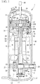
- Fig. 1 is a longitudinal cross-sectional view of a two-stage compressor according to the first embodiment of the present invention
- Fig. 2 is a cross-sectional view of a low-stage-side rotary compressor of the two-stage compressor.
- the high-stage-side compressor 3 is not limited to the scroll-type compressor 3.
- the below described two-stage compressor 1 is preferably used as a two-stage compressor which uses an HFC refrigerant, an HFO refrigerant, an HC refrigerant, or a mixed refrigerant of these refrigerants.
- the refrigerant described hereinafter refers to the HFC, the HFO, the HC, or the mixed refrigerant of these refrigerants.
- the two-stage compressor 1 includes a housing 10 having a hermetic structure.
- An electric motor 4 which has a stator 5 and a rotor 6 is installed and fixed at an approximately center part of the inside of the housing 10, and a rotary shaft (crank shaft) 7 is integrally connected to the rotor 6.
- a rotary compressor 2 which is the low-stage-side compressor (hereinafter referred to as low-stage-side rotary compressor 2) is installed under the electric motor 4.
- the low-stage-side rotary compressor 2 includes a cylinder chamber 20, and also includes the following elements: a cylinder main body 21 installed and fixed in the housing 10; an upper bearing 22 and a lower bearing 23 installed and fixed on and under the cylinder main body 21, and sealing an upper part and an lower part of the cylinder chamber 20; a rotor 24 fitted to a crank part 7A of the rotary shaft 7, for rotating along an inner circumferential surface of the cylinder chamber 20; a blade 26 fitted into a blade groove 25 of the cylinder main body 21 and reciprocating along the groove and having a tip in contact with an outer circumference of the rotor 24 so as to partition the inside of the cylinder chamber 20 into a suction side and a compression side; and a blade pressing spring 27 pressing a rear end of the blade 26, and the like.
- the low-stage-side rotary compressor 2 which may have known components, is configured to suck a low-pressure refrigerant gas (working gas) into the cylinder chamber 20 through a suction pipe 28, and after compressing the refrigerant gas to an intermediate pressure by rotation of the rotor 24, discharge the gas into the inside of the housing 10 through a discharge chamber 29.
- This intermediate-pressure refrigerant gas flows through a gas passage hole 6A and so on provided in the rotor 6 of the electric motor 4 into an upper space of the electric motor 4, and is sucked into the high-stage-side compressor 3 and compressed thus in two stages.
- the high-stage-side compressor 3 is a scroll compressor including a pair of a fixed scroll 32 and an orbiting scroll 33 (hereinafter referred to as high-stage-side scroll compressor 3).
- the high-stage-side scroll compressor 3 is connected to the rotary shaft 7 above the electric motor 4 inside the housing 10, and installed so as to be driven through the rotary shaft 7 by rotation of the electric motor 4.
- the high-stage-side scroll compressor 3 includes a bearing 30 supporting the rotary shaft 7.
- the high-stage-side scroll compressor 3 also includes a support member 31 fixed and installed in the housing 10, and the fixed scroll 32 and the orbiting scroll 33, which have spiral laps 32B and 33B erected on end plates 32A and 33A, respectively, and which are installed on the support member 31 with the spiral laps 32B and 33B engaged with each other so as to constitute a pair of compression chambers 34.
- the high-stage-side scroll compressor 3 further includes the following elements: a orbiting boss part 35 for connecting the orbiting scroll 33 and an eccentric pin 7B provided at a shaft end of the rotary shaft 7 and for driving the orbiting scroll 33 to move in an orbiting manner; a rotation prevention mechanism 36, such as an Oldham's link, which is disposed between the orbiting scroll 33 and the support member 31 and causes the orbiting scroll 33 to move in the orbiting manner while preventing the orbiting scroll 33 from rotating; a discharge valve 37 disposed on a back surface of the fixed scroll 32; and a discharge cover 39 fixed and installed on the back surface of the fixed scroll 32 and forming a discharge chamber 38 between the fixed scroll 32 and the discharge cover 39.
- a rotation prevention mechanism 36 such as an Oldham's link
- the high-stage-side scroll compressor 3 which may be known, is configured to suck the refrigerant gas which is compressed to an intermediate pressure in the low-stage-side rotary compressor 2 and discharged inside the housing 10 into the compression chamber 34. And then, after compressing the gas to a discharge pressure (high pressure) by driving the orbiting scroll 33 in the orbiting manner, the high-stage-side scroll compressor 3 discharge the gas through the discharge valve 37 into the discharge chamber 38.
- the high-pressure refrigerant gas is discharged from the discharge chamber 38 through a discharge pipe 40 to the outside of the compressor, namely, to a refrigeration cycle side.
- the support member 31 constituting the high-stage-side scroll compressor 3 is fixed and installed with a screw to a bracket 41 provided inside the housing 10.
- a known positive-displacement lubrication pump 11 is installed between a lower end portion of the rotary shaft 7 and the lower bearing 23 of the low-stage-side rotary compressor 2.
- the positive-displacement lubrication pump 11 pumps up lubricant oil 12 housed in a bottom part of the housing 10, and feeds the lubricant oil 12, through an oil feed hole 13 provided inside the rotary shaft 7, to parts requiring lubrication such as the bearing parts of the low-stage-side rotary compressor 2 and the high-stage-side scroll compressor 3.
- an oil separating plate 42 rotated integrally with the rotor 6 is provided at an upper end of the rotor 6 of the electric motor 4.
- This oil separating plate 42 is a disc installed on a balance weight 43 provided on the upper end of the rotor 6 (if the balance weight is not installed, the oil separating plate is installed through a spacer, etc.), and has an outer diameter such that a slight gap is made between the oil separating plate and an inner circumference of a stator coil end 5A of the electric motor 4.
- the oil separating plate 42 has a through-hole (not shown) provided at a center part so as to allow the rotary shaft 7 to pass through the separating plate 42.
- the through-hole has a diameter such that the inner circumferential edge thereof is positioned on a center side relative to the gas passage holes 6A provided in the rotor 6, and that the gap between the through-hole and the outer circumferential surface of the rotary shaft 7 is made as small as possible.
- the two-stage compressor 1 is configured to discharge the refrigerant compressed to an intermediate pressure in the low-stage-side rotary compressor 2 inside the housing 10, the two-stage compressor 1 itself is an intermediate-pressure-housing type two-stage compressor 1.
- the back pressure applied to the back surface of the blade 26 corresponds to the intermediate pressure which is the pressure inside the housing 10.
- the back pressure applied to the blade 26 corresponds to the differential pressure between the low pressure inside the cylinder chamber 20 and the intermediate pressure outside the cylinder chamber 20, which is approximately half of that in a single-stage rotary compressor where the differential pressure between the low pressure and the high pressure is applied to the blade.
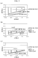
- Fig. 3 is a chart comparing a single-stage rotary compressor and the low-stage-side rotary compressor.
- Fig. 3 (A) shows a case of a common single-stage rotary compressor.
- the back pressure applied to the blade 26 corresponds to a differential pressure between a low pressure LP and a high pressure HP, and the compressor can be operated at an operating point within ranges above the blade jumping line, that is, where gas leakage in the cylinder is not caused due to blade jumping.
- the back pressure applied to the blade 26 corresponds to a differential pressure between a low pressure LP and a high pressure HP
- the compressor can be operated at an operating point within ranges above the blade jumping line, that is, where gas leakage in the cylinder is not caused due to blade jumping.
- Fig. 3 shows a case as shown in Fig.
- the back pressure applied to the blade 26 corresponds to a differential pressure between the low pressure LP and an intermediate pressure MP, which is approximately half of that in Fig. 3 (A) .
- the blade 26 here is an example using a material having a density of 7 g/cm 3 .
- the blade 26 is configured with a material having a density of 3 g/cm 3 or less to make the blade lighter and sufficiently reduce the inertial force during reciprocating motion, so that, as shown in Fig. 3 (C) , the blade jumping ranges are reduced and sufficiently wide ranges are secured where it is possible to operate at high efficiency.
- a carbon blade, an aluminum alloy blade, an aluminum alloy blade plated with SiC-dispersed Ni-P, or the like can be adopted as the blade 26.
- the rotor 24, which has sliding contact with the blade 26, and the cylinder main body 21 are made of alloy steel or cast iron.
- the present embodiment provides the following effects.
- the low-pressure refrigerant gas directly sucked through the suction pipe 28 into the cylinder chamber 20 of the low-stage-side rotary compressor 2 is compressed to an intermediate pressure by rotation of the rotor 24, and thereafter discharged into the discharge chamber 29.
- the intermediate-pressure refrigerant gas flows through the gas passage hole 6A and the like provided in the rotor 6 of the electric motor 4 into the upper space provided above the electric motor 4.
- the refrigerant gas having flowed into the upper space collides against the rotating oil separating plate 42, so that the lubricant oil 12 is separated by centrifugal separation action and the lubricant oil 12 falls in drops to the bottom part of the housing 10.
- the intermediate-pressure refrigerant gas having flowed into the upper space of the electric motor 4 is guided through gaps between the housing 10 and the support member 31 constituting part of the high-stage-side scroll compressor 3 and the like, to a suction port of the high-stage-side scroll compressor 3 configured in the fixed scroll 32, and sucked into the compression chamber 34.
- the intermediate-pressure refrigerant gas sucked into the compression chamber 34 is compressed to a high pressure by the high-stage-side scroll compressor 3 thus in two stages, and thereafter discharged from the discharge valve 37 into the discharge chamber 38 and delivered through the discharge pipe 40 to the outside of the compressor, namely, to the refrigeration cycle side.
- the inside of the housing 10, where the refrigerant compressed to an intermediate pressure in the low-stage-side rotary compressor 2 is discharged is at an intermediate pressure.
- the back pressure applied to the blade 26 corresponds to the differential pressure between the low pressure and the intermediate pressure.
- the blade 26 is made of a material having a density of 3 g/cm 3 or less and lightweight enough to reduce the inertial force during reciprocating motion, despite the lower differential pressure. Accordingly, as shown in Fig. 3 (C) , the blade jumping ranges can be reduced so as to sufficiently secure the sufficiently wide ranges where it is possible to operate at high efficiency.
- the above-described blade 26 is a carbon blade, an aluminum alloy blade, or an aluminum alloy blade plated with SiC-dispersed Ni-P, and the rotor 24, which the blade 26 has sliding contact with, and the cylinder main body 21 are made of alloy steel or cast iron.
- the blade 26, the rotor 24, and the cylinder main body 21 can be configured in such a manner that those elements are excellent in heat resistance and abrasion resistance. Accordingly, it is possible to provide the highly reliable two-stage compressor 1 in which heat resistance and abrasion resistance of the low-stage-side rotary compressor 2 are sufficiently secured.
- the low-stage-side compressor of the two-stage compressor 1 is the rotary compressor 2 and the high-stage-side compressor thereof is the scroll compressor 3.
- the high efficiency scroll compressor 3 which has been used in wide-ranging applications and causes little compression leakage, is adopted as the high-stage-side compressor
- the rotary compressor 2 which is equipped with the blade 26 as described above made of a material having a density of 3 g/cm 3 or less, is adopted as the low-stage-side compressor, it is possible to configure the two-stage compressor 1 in which leakage loss is made small in both the low-stage-side compressor and the high-stage-side compressor.
- the efficiency of the two-stage compressor 1 can be enhanced.
- the refrigerant applied to the two-stage compressor 1 is the HFC refrigerant, the HFO refrigerant, the HC refrigerant, which are considered not to destroy the ozone layer, or a mixed refrigerant of these refrigerants. Therefore, even when, in the two-stage compressor 1 where the differential pressure between the low pressure and the intermediate pressure is small, and even when the rotary compressor 2 is adopted as the low-stage-side compressor of the intermediate-pressure-housing type two-stage compressor, it is possible to reduce the inertial force of the blade 26 during reciprocating motion sufficiently and to suppress blade jumping.
- the two-stage compressor 1 which uses the HFC refrigerant, the HFO refrigerant, the HC refrigerant, or the mixed refrigerant of these refrigerants, it is possible to reduce the operating range where blade jumping, and accordingly gas leakage, occurs inside the cylinder so as to secure the range where high efficient operation is possible, and thereby to enhance the efficiency of the two-stage compressor 1.
- This embodiment is different from the above-described first embodiment, this embodiment has a different configuration in which the low-stage-side compressor and the high-stage-side compressor are connected in series to configure a two-stage compression system. As other configurations are similar to those of the first embodiment, descriptions for those configurations will be omitted below.
- the two-stage compression system is configured by the low-stage-side rotary compressor, which is the above-described rotary compressor 2 provided in an independent housing, and the high-stage-side scroll compressor, which is the above-described scroll compressor 3 provided in another independent housing, connected in series through a pipe.
- the low-stage-side rotary compressor is an intermediate-pressure-housing type compressor in which a refrigerant compressed to an intermediate-pressure is discharged inside the housing, and the intermediate-pressure refrigerant gas discharged inside the intermediate-pressure housing is sucked through the pipe into the high-stage-side scroll compressor and compressed thus in two stages.
- the low-stage-side compressor is the rotary compressor and the high-stage-side compressor is the scroll compressor.
- the high-stage-side compressor does not necessarily have to be the scroll compressor, and other types of compressors, including a rotary compressor, may be employed.
- the blade of the high-stage-side rotary compressor in which the housing has a high-pressure structure, does not necessarily have to be configured as described above to suppress blade jumping.
Landscapes
- Engineering & Computer Science (AREA)
- Mechanical Engineering (AREA)
- General Engineering & Computer Science (AREA)
- Applications Or Details Of Rotary Compressors (AREA)
- Compressors, Vaccum Pumps And Other Relevant Systems (AREA)
Description
- The present invention relates to a two-stage compressor and a two-stage compression system in which refrigerant gas is compressed from a low pressure to a high pressure through two stages.
- In a two-stage compressor and a two-stage compression system, since low-pressure refrigerant gas is compressed through two stages, that is, a low-stage-side compressor for compression from a low pressure to an intermediate pressure, and a high-stage-side compressor for compression from the intermediate pressure to a high pressure, a differential pressure in each compressor can be made small. This allows leakage loss in each compressor to be made small and the compression efficiency to be enhanced.
- As a specific example,
Patent Literature 1 discloses a two-stage compressor which includes two compressors provided in a single hermetic housing. One of the two compressors is a rotary compressor on a low-stage-side and the other is a scroll compressor on a high-stage-side, and a refrigerant compressed to an intermediate pressure in the low-stage-side rotary compressor is discharged to the housing and the intermediate-pressure refrigerant is sucked into the high-stage-side scroll compressor, and thus the refrigerant is compressed through two stages.Patent Literature 2 discloses a substantially similar two-stage compressor in which low-stage-side and high-stage-side compressors are both configured as a rotary compressor. Further,Patent Literature 3 discloses an example of a two-stage compression system, in which two independent compressors, i.e. low-stage-side compressor and high-pressure-stage-side compressor, are connected in series to perform two-stage compression. - On the other hand, in a single-stage rotary compressor in which a low-pressure refrigerant is compressed to a high pressure by a single compressor, since the compressor rotating speed is higher by the inverter control, a blade, which reciprocates with contacting an outer circumferential surface of the rotor fails to follow the rotation due to an increase in its own inertial force at higher speed. This leads to so-called blade jumping, which causes gas leakage inside the cylinder. To cope with this phenomenon, various technologies, including one for making the blade lighter, have been proposed by Patent Literatures 4 to 6 and the like.
-
- {PTL 1} Japanese Unexamined Patent Application, Publication No.
2008-190377 - {PTL 2} Japanese Unexamined Patent Application, Publication No.
2008-286037 - {PTL 3} Japanese Unexamined Patent Application, Publication No.
2009-192164 - {PTL 4} Japanese Unexamined Utility Model Application, Publication No.
S62-193194 - {PTL 5} Japanese Unexamined Utility Model Application, Publication No.
H1-152090 - {PTL 6} Japanese Unexamined Patent Application, Publication No.
H3-197628 - As described above, efforts have been made in the single-stage rotary compressor, and one of them was making the blade lighter so as to reduce the inertial force of the blade itself and prevent the blade from causing blade jumping at an operating point. However, even though the blade is made lighter to such a degree as to prevent blade jumping in the single-stage rotary compressor where a low-pressure refrigerant is compressed to a high pressure, when the rotary compressor is used as a low-stage-side compressor of an intermediate-pressure-housing type two-stage compressor or two-stage compression system, in which the inside of the housing is at an intermediate pressure, gas leakage is caused inside the cylinder due to blade jumping.
- The low-stage-side compressor of the two-stage compressor or the two-stage compression system serves to compress a low-pressure refrigerant to an intermediate pressure. Therefore, when the intermediate-pressure-housing type rotary compressor is adopted as the low-stage-side compressor, a back pressure applied to a back surface of the blade corresponds to the differential pressure between the low pressure inside the cylinder chamber and the intermediate pressure outside the cylinder chamber. It is thus conceivable that the aforementioned blade jumping has been caused by the fact that the back pressure applied to the back surface of the blade is lower compared to the single-stage rotary compressor where the differential pressure between the low pressure and the high pressure is applied as the back pressure.
- The present invention is made in view of such circumstances, and the object is to provide a two-stage compressor and a two-stage compression system capable of, even when the intermediate-pressure-housing type rotary compressor is used as the low-stage-side compressor of the two-stage compressor or the two-stage compression system, enabling compressors to be operated efficiently at sufficiently wide range without blade jumping.
- In order to solve the above problems, the two-stage compressor and the two-stage compression system of the present invention employ the solutions defined by the appended claims.
- The two-stage compressor according to the present invention is an intermediate-pressure-housing type two-stage compressor comprising a low-stage-side compressor and a high-stage-side compressor both provided in a housing, wherein a refrigerant gas compressed to an intermediate pressure by the low-stage-side compressor is discharged inside the housing, and the refrigerant gas compressed to the intermediate pressure is sucked into the high-stage-side compressor to be compressed to a high pressure, wherein the low-stage-side compressor is a rotary compressor provided with a blade partitioning an inside of a cylinder chamber into a suction side and a compression side, and the blade reciprocates in response to rotation of a rotor and wherein the blade is formed of a material having a density of 3 g/cm3 or less so as to reduce inertial force of the blade in consideration of a low back pressure acting on a back surface of the blade.
- According to the present invention, in the intermediate-pressure-housing type two-stage compressor where a refrigerant compressed to an intermediate pressure in the low-stage-side compressor is discharged inside the housing and the inside of the housing is at the intermediate pressure, the low-stage-side compressor is the rotary compressor provided with the blade partitioning the inside of the cylinder chamber into the suction side and the compression side, the blade reciprocating in response to rotation of the rotor, the blade being formed of a material having a density of 3 g/cm3 or less so as to reduce the blade's inertial force in consideration of the lower back pressure acting on the back surface of the blade. Therefore, even when the low-stage-side compressor of the two-stage compressor which compresses a refrigerant from a low pressure to an intermediate pressure is configured with the rotary compressor, the blade is made of a material having a density of 3 g/cm3 or less and lightweight enough to reduce the inertial force during reciprocating motion and suppress so-called blade jumping, despite the fact that the lower back pressure corresponding to the differential pressure between the intermediate pressure and the low pressure is applied to the back surface of the blade. Accordingly, it is possible to operate without blade jumping, and accordingly without large gas leakage inside the cylinder, and then, it is possible to secure the sufficiently wide range where compressor efficiency is high, and thereby to reduce leakage loss in the low-stage-side rotary compressor in order to enhance the compression efficiency of the two-stage compressor.
- Further, the two-stage compression system according to the present invention is a two-stage compression system comprising: a low-stage-side compressor having a compression system housed in a housing; and a high-stage-side compressor having a compression system housed in another housing and connected in series with the low-stage-side compressor, wherein a refrigerant gas is compressed to an intermediate-pressure in the low-stage-side compressor and it is discharged inside the housing, and then it is sucked into the high-stage-side compressor to be compressed to a high pressure, wherein the low-stage-side compressor is an intermediate-pressure-housing type and also is a rotary compressor provided with a blade partitioning an inside of a cylinder chamber into a suction side and a compression side, and the blade reciprocates in response to rotation of a rotor, and wherein the blade is formed of a material having a density of 3 g/cm3 or less so as to reduce inertial force of the blade in consideration of a low back pressure acting on a back surface of the blade.
- According to the present invention, in the two-stage compression system in which the low-stage-side compressor and the high-stage-side compressor are connected in series, and the low-stage-side compressor is the intermediate-pressure-housing type compressor, the intermediate-pressure-housing type low-stage-side compressor is the rotary compressor provided with the blade partitioning the inside of the cylinder chamber into the suction side and the compression side, the blade reciprocating in response to rotation of the rotor, the blade being formed of a material having a density of 3 g/cm3 or less so as to reduce the blade's inertial force in response to the lower back pressure acting on the back surface of the blade. Therefore, even when the low-stage-side compressor of the two-stage compression system which compresses a refrigerant from a low pressure to an intermediate pressure is configured as a rotary compressor, the blade is made of a material having a density of 3 g/cm3 or less and lightweight enough to reduce the inertial force during reciprocating motion and suppress so-called blade jumping, despite the fact that the lower back pressure corresponding to the differential pressure between the intermediate pressure and the low pressure is applied to the back surface of the blade. Accordingly, it is possible to operate without blade jumping, and accordingly without large gas leakage inside the cylinder, and then, it is possible to secure the sufficiently wide range where compressor efficiency is high, and thereby to reduce leakage loss in the low-stage-side rotary compressor in order to enhance the compression efficiency of the two-stage compression system.
- Furthermore, according to the present invention, in the two-stage compressor or the two-stage compression system described above, the low-stage-side compressor is the rotary compressor and the high-stage-side compressor is a scroll compressor or a rotary compressor.
- According to the present invention, the low-stage-side compressor is the rotary compressor and the high-stage-side compressor is a scroll compressor or a rotary compressor. Therefore, by adopting a scroll compressor or a rotary compressor, which have conventionally been used in wide-ranging applications, as the high-stage-side compressor, and adopting the rotary compressor as described above provided with the blade made of a material having a density of 3 g/cm3 or less as the low-stage-side compressor, it is possible to configure the two-stage compressor or the two-stage compression system in which leakage loss is made small in both the low-stage-side compressor and the high-stage-side compressor. Thus, the efficiency of the two-stage compressor or the two-stage compression system can be enhanced.
- Moreover, according to the present invention, in either one of the two-stage compressor or the two-stage compression system described above, the blade is a carbon blade, an aluminum alloy blade, or an aluminum alloy blade plated with SiC-dispersed Ni-P, and the rotor and a cylinder main body are made of alloy steel or cast iron.
- According to the present invention, the blade is the carbon blade, the aluminum alloy blade, or the aluminum alloy blade plated with SiC-dispersed Ni-P, and the rotor and the cylinder main body are made of alloy steel or cast iron. Therefore, the blade, the rotor, and the cylinder main body can be configured in such a manner in which those elements are excellent in heat resistance and abrasion resistance. Accordingly, it is possible to provide the highly reliable two-stage compressor and two-stage compression system in which heat resistance and abrasion resistance of the low-stage-side rotary compressor are sufficiently secured.
- In addition, according to the present invention, in either one of the two-stage compressor or the two-stage compression system described above, the refrigerant is an HFC refrigerant, an HFO refrigerant, an HC refrigerant, or a mixed refrigerant of two or more of the aforementioned refrigerants.
- According to the present invention, the refrigerant is the HFC refrigerant, the HFO refrigerant, the HC refrigerant, or the mixed refrigerant of these refrigerants. Therefore, by using the HFC refrigerant, the HFO refrigerant, the HC refrigerant, which are considered not to destroy the ozone layer, or the mixed refrigerant of these refrigerants, even when, in the two-stage compressor and the two-stage compression system where the differential pressure between the low pressure and the intermediate pressure is small, and even when the low-stage-side compressor of the intermediate-pressure-housing type two-stage compressor and the intermediate-pressure-housing type low-stage-side compressor of the two-stage compression system is each configured with a rotary compressor, it is possible to sufficiently reduce the blade's inertial force during reciprocating motion and suppress blade jumping. Accordingly, in the two-stage compressor or the two-stage compression system which uses the HFC refrigerant, the HFO refrigerant, the HC refrigerant, or the mixed refrigerant of these refrigerants, it is possible to operate without blade jumping, and accordingly without large gas leakage inside the cylinder, and then, it is possible to secure the sufficiently wide range where compressor efficiency is high, and thereby to enhance the compression efficiency of the two-stage compressor or the two-stage compression system.
- According to the two-stage compressor and the two-stage compression system of the present invention, even when the low-stage-side compressor of the two-stage compressor or the two-stage compression system which compresses a refrigerant from a low pressure to an intermediate pressure is configured with the rotary compressor, the blade is made of a material having a density of 3 g/cm3 or less and lightweight enough to reduce the inertial force during reciprocating motion and suppress so-called blade jumping, despite the fact that the lower back pressure corresponding to the differential pressure between the intermediate pressure and the low pressure is applied to the back surface of the blade. Accordingly, it is possible to operate without blade jumping, and accordingly without large gas leakage inside the cylinder, and then, it is possible to secure the sufficiently wide range where compressor efficiency is high, and thereby to reduce leakage loss in the low-stage-side rotary compressor in order to enhance the compression efficiency of the two-stage compressor or the two-stage compression system.
-
- {
Fig. 1} Fig. 1 is a longitudinal cross-sectional view of a two-stage compressor according to a first embodiment of the present invention. - {
Fig. 2} Fig. 2 is a cross-sectional view of a low-stage-side rotary compressor of the two-stage compressor shown inFig. 1 . - {
Fig. 3} Figs. 3 (A), (B), and (C) are charts showing compression operations with a lower differential pressure as a back pressure of a blade. - Hereinbelow, embodiments according to the present invention will be described with reference to the drawings.
- A first embodiment of the present invention will be described using
Figs. 1 to 3 . -
Fig. 1 is a longitudinal cross-sectional view of a two-stage compressor according to the first embodiment of the present invention, andFig. 2 is a cross-sectional view of a low-stage-side rotary compressor of the two-stage compressor. - In this embodiment, a description is made for an example of a two-
stage compressor 1 in which a rotary compressor is adopted as a low-stage-side compressor 2 and a scroll compressor is adopted as a high-stage-side compressor 3. However, the high-stage-side compressor 3 is not limited to the scroll-type compressor 3. The below described two-stage compressor 1 is preferably used as a two-stage compressor which uses an HFC refrigerant, an HFO refrigerant, an HC refrigerant, or a mixed refrigerant of these refrigerants. The refrigerant described hereinafter refers to the HFC, the HFO, the HC, or the mixed refrigerant of these refrigerants. - The two-
stage compressor 1 includes ahousing 10 having a hermetic structure. An electric motor 4 which has a stator 5 and arotor 6 is installed and fixed at an approximately center part of the inside of thehousing 10, and a rotary shaft (crank shaft) 7 is integrally connected to therotor 6. Arotary compressor 2 which is the low-stage-side compressor (hereinafter referred to as low-stage-side rotary compressor 2) is installed under the electric motor 4. - The low-stage-
side rotary compressor 2 includes acylinder chamber 20, and also includes the following elements: a cylindermain body 21 installed and fixed in thehousing 10; anupper bearing 22 and alower bearing 23 installed and fixed on and under the cylindermain body 21, and sealing an upper part and an lower part of thecylinder chamber 20; arotor 24 fitted to a crankpart 7A of therotary shaft 7, for rotating along an inner circumferential surface of thecylinder chamber 20; ablade 26 fitted into ablade groove 25 of the cylindermain body 21 and reciprocating along the groove and having a tip in contact with an outer circumference of therotor 24 so as to partition the inside of thecylinder chamber 20 into a suction side and a compression side; and ablade pressing spring 27 pressing a rear end of theblade 26, and the like. - The low-stage-
side rotary compressor 2, which may have known components, is configured to suck a low-pressure refrigerant gas (working gas) into thecylinder chamber 20 through asuction pipe 28, and after compressing the refrigerant gas to an intermediate pressure by rotation of therotor 24, discharge the gas into the inside of thehousing 10 through adischarge chamber 29. This intermediate-pressure refrigerant gas flows through agas passage hole 6A and so on provided in therotor 6 of the electric motor 4 into an upper space of the electric motor 4, and is sucked into the high-stage-side compressor 3 and compressed thus in two stages. - The high-stage-
side compressor 3 is a scroll compressor including a pair of a fixedscroll 32 and an orbiting scroll 33 (hereinafter referred to as high-stage-side scroll compressor 3). The high-stage-side scroll compressor 3 is connected to therotary shaft 7 above the electric motor 4 inside thehousing 10, and installed so as to be driven through therotary shaft 7 by rotation of the electric motor 4. - The high-stage-
side scroll compressor 3 includes abearing 30 supporting therotary shaft 7. The high-stage-side scroll compressor 3 also includes asupport member 31 fixed and installed in thehousing 10, and the fixedscroll 32 and the orbitingscroll 33, which havespiral laps end plates support member 31 with thespiral laps compression chambers 34. The high-stage-side scroll compressor 3 further includes the following elements: a orbitingboss part 35 for connecting the orbitingscroll 33 and aneccentric pin 7B provided at a shaft end of therotary shaft 7 and for driving theorbiting scroll 33 to move in an orbiting manner; arotation prevention mechanism 36, such as an Oldham's link, which is disposed between the orbitingscroll 33 and thesupport member 31 and causes theorbiting scroll 33 to move in the orbiting manner while preventing the orbitingscroll 33 from rotating; adischarge valve 37 disposed on a back surface of the fixedscroll 32; and a discharge cover 39 fixed and installed on the back surface of the fixedscroll 32 and forming adischarge chamber 38 between the fixedscroll 32 and the discharge cover 39. - The high-stage-
side scroll compressor 3, which may be known, is configured to suck the refrigerant gas which is compressed to an intermediate pressure in the low-stage-side rotary compressor 2 and discharged inside thehousing 10 into thecompression chamber 34. And then, after compressing the gas to a discharge pressure (high pressure) by driving theorbiting scroll 33 in the orbiting manner, the high-stage-side scroll compressor 3 discharge the gas through thedischarge valve 37 into thedischarge chamber 38. The high-pressure refrigerant gas is discharged from thedischarge chamber 38 through adischarge pipe 40 to the outside of the compressor, namely, to a refrigeration cycle side. Thesupport member 31 constituting the high-stage-side scroll compressor 3 is fixed and installed with a screw to abracket 41 provided inside thehousing 10. - A known positive-
displacement lubrication pump 11 is installed between a lower end portion of therotary shaft 7 and thelower bearing 23 of the low-stage-side rotary compressor 2. The positive-displacement lubrication pump 11 pumps uplubricant oil 12 housed in a bottom part of thehousing 10, and feeds thelubricant oil 12, through anoil feed hole 13 provided inside therotary shaft 7, to parts requiring lubrication such as the bearing parts of the low-stage-side rotary compressor 2 and the high-stage-side scroll compressor 3. In addition, anoil separating plate 42 rotated integrally with therotor 6 is provided at an upper end of therotor 6 of the electric motor 4. - This
oil separating plate 42 is a disc installed on abalance weight 43 provided on the upper end of the rotor 6 (if the balance weight is not installed, the oil separating plate is installed through a spacer, etc.), and has an outer diameter such that a slight gap is made between the oil separating plate and an inner circumference of astator coil end 5A of the electric motor 4. Theoil separating plate 42 has a through-hole (not shown) provided at a center part so as to allow therotary shaft 7 to pass through the separatingplate 42. It is preferable that the through-hole has a diameter such that the inner circumferential edge thereof is positioned on a center side relative to the gas passage holes 6A provided in therotor 6, and that the gap between the through-hole and the outer circumferential surface of therotary shaft 7 is made as small as possible. - Since the above-described two-
stage compressor 1 is configured to discharge the refrigerant compressed to an intermediate pressure in the low-stage-side rotary compressor 2 inside thehousing 10, the two-stage compressor 1 itself is an intermediate-pressure-housing type two-stage compressor 1. By providing the low-stage-side rotary compressor 2 inside thehousing 10 having such a structure with an intermediate-pressure, the back pressure applied to the back surface of theblade 26 corresponds to the intermediate pressure which is the pressure inside thehousing 10. Thus, the back pressure applied to theblade 26 corresponds to the differential pressure between the low pressure inside thecylinder chamber 20 and the intermediate pressure outside thecylinder chamber 20, which is approximately half of that in a single-stage rotary compressor where the differential pressure between the low pressure and the high pressure is applied to the blade. -
Fig. 3 is a chart comparing a single-stage rotary compressor and the low-stage-side rotary compressor.Fig. 3 (A) shows a case of a common single-stage rotary compressor. InFig. 3 (A) , the back pressure applied to theblade 26 corresponds to a differential pressure between a low pressure LP and a high pressure HP, and the compressor can be operated at an operating point within ranges above the blade jumping line, that is, where gas leakage in the cylinder is not caused due to blade jumping. On the other hand, in a case as shown inFig. 3 (B) where this single-stage rotary compressor is applied as the low-stage-side rotary compressor 2, the back pressure applied to theblade 26 corresponds to a differential pressure between the low pressure LP and an intermediate pressure MP, which is approximately half of that inFig. 3 (A) . For this reason, even the operating points, which are within the operating range in the case of the single-stage rotary compressor, fall within the blade jumping range. Note that, theblade 26 here is an example using a material having a density of 7 g/cm3. - Therefore, in the present embodiment, the
blade 26 is configured with a material having a density of 3 g/cm3 or less to make the blade lighter and sufficiently reduce the inertial force during reciprocating motion, so that, as shown inFig. 3 (C) , the blade jumping ranges are reduced and sufficiently wide ranges are secured where it is possible to operate at high efficiency. In consideration of heat resistance and abrasion resistance, a carbon blade, an aluminum alloy blade, an aluminum alloy blade plated with SiC-dispersed Ni-P, or the like can be adopted as theblade 26. It is preferable that therotor 24, which has sliding contact with theblade 26, and the cylindermain body 21 are made of alloy steel or cast iron. - Due to the above-described configuration, the present embodiment provides the following effects.
- The low-pressure refrigerant gas directly sucked through the
suction pipe 28 into thecylinder chamber 20 of the low-stage-side rotary compressor 2 is compressed to an intermediate pressure by rotation of therotor 24, and thereafter discharged into thedischarge chamber 29. After being discharged from thedischarge chamber 29 into the lower space provided below the electric motor 4, the intermediate-pressure refrigerant gas flows through thegas passage hole 6A and the like provided in therotor 6 of the electric motor 4 into the upper space provided above the electric motor 4. The refrigerant gas having flowed into the upper space collides against the rotatingoil separating plate 42, so that thelubricant oil 12 is separated by centrifugal separation action and thelubricant oil 12 falls in drops to the bottom part of thehousing 10. - The intermediate-pressure refrigerant gas having flowed into the upper space of the electric motor 4 is guided through gaps between the
housing 10 and thesupport member 31 constituting part of the high-stage-side scroll compressor 3 and the like, to a suction port of the high-stage-side scroll compressor 3 configured in the fixedscroll 32, and sucked into thecompression chamber 34. The intermediate-pressure refrigerant gas sucked into thecompression chamber 34 is compressed to a high pressure by the high-stage-side scroll compressor 3 thus in two stages, and thereafter discharged from thedischarge valve 37 into thedischarge chamber 38 and delivered through thedischarge pipe 40 to the outside of the compressor, namely, to the refrigeration cycle side. - In this two-stage compression process, the inside of the
housing 10, where the refrigerant compressed to an intermediate pressure in the low-stage-side rotary compressor 2 is discharged, is at an intermediate pressure. This means that the intermediate pressure is also applied to the back surface of theblade 26 of the low-stage-side rotary compressor 2. Thus, the back pressure applied to theblade 26 corresponds to the differential pressure between the low pressure and the intermediate pressure. Here, theblade 26 is made of a material having a density of 3 g/cm3 or less and lightweight enough to reduce the inertial force during reciprocating motion, despite the lower differential pressure. Accordingly, as shown inFig. 3 (C) , the blade jumping ranges can be reduced so as to sufficiently secure the sufficiently wide ranges where it is possible to operate at high efficiency. - Thus, it is possible to operate without blade jumping, and accordingly without large gas leakage inside the cylinder, and then, it is possible to secure the sufficiently wide range where compressor efficiency is high, and thereby to reduce leakage loss in the low-stage-
side rotary compressor 2 in order to enhance the compression efficiency of the two-stage compressor 1. - Further, the above-described
blade 26 is a carbon blade, an aluminum alloy blade, or an aluminum alloy blade plated with SiC-dispersed Ni-P, and therotor 24, which theblade 26 has sliding contact with, and the cylindermain body 21 are made of alloy steel or cast iron. Thus, theblade 26, therotor 24, and the cylindermain body 21 can be configured in such a manner that those elements are excellent in heat resistance and abrasion resistance. Accordingly, it is possible to provide the highly reliable two-stage compressor 1 in which heat resistance and abrasion resistance of the low-stage-side rotary compressor 2 are sufficiently secured. - Furthermore, the low-stage-side compressor of the two-
stage compressor 1 is therotary compressor 2 and the high-stage-side compressor thereof is thescroll compressor 3. As the highefficiency scroll compressor 3, which has been used in wide-ranging applications and causes little compression leakage, is adopted as the high-stage-side compressor, and therotary compressor 2, which is equipped with theblade 26 as described above made of a material having a density of 3 g/cm3 or less, is adopted as the low-stage-side compressor, it is possible to configure the two-stage compressor 1 in which leakage loss is made small in both the low-stage-side compressor and the high-stage-side compressor. Thus, the efficiency of the two-stage compressor 1 can be enhanced. - Moreover, the refrigerant applied to the two-
stage compressor 1 is the HFC refrigerant, the HFO refrigerant, the HC refrigerant, which are considered not to destroy the ozone layer, or a mixed refrigerant of these refrigerants. Therefore, even when, in the two-stage compressor 1 where the differential pressure between the low pressure and the intermediate pressure is small, and even when therotary compressor 2 is adopted as the low-stage-side compressor of the intermediate-pressure-housing type two-stage compressor, it is possible to reduce the inertial force of theblade 26 during reciprocating motion sufficiently and to suppress blade jumping. Thus, in the two-stage compressor 1 which uses the HFC refrigerant, the HFO refrigerant, the HC refrigerant, or the mixed refrigerant of these refrigerants, it is possible to reduce the operating range where blade jumping, and accordingly gas leakage, occurs inside the cylinder so as to secure the range where high efficient operation is possible, and thereby to enhance the efficiency of the two-stage compressor 1. - Next, a second embodiment of the present invention will be described.
- This embodiment is different from the above-described first embodiment, this embodiment has a different configuration in which the low-stage-side compressor and the high-stage-side compressor are connected in series to configure a two-stage compression system. As other configurations are similar to those of the first embodiment, descriptions for those configurations will be omitted below.
- In the present embodiment, the two-stage compression system is configured by the low-stage-side rotary compressor, which is the above-described
rotary compressor 2 provided in an independent housing, and the high-stage-side scroll compressor, which is the above-describedscroll compressor 3 provided in another independent housing, connected in series through a pipe. - The low-stage-side rotary compressor is an intermediate-pressure-housing type compressor in which a refrigerant compressed to an intermediate-pressure is discharged inside the housing, and the intermediate-pressure refrigerant gas discharged inside the intermediate-pressure housing is sucked through the pipe into the high-stage-side scroll compressor and compressed thus in two stages.
- As described above, also in the two-stage compression system configured with two independent single-stage compressors connected in series, when the rotary compressor is adopted as the low-stage-side compressor, the aforementioned situation arises in the low-stage-
side rotary compressor 2. This problem can be solved by adopting a blade made of a material having a density of 3 g/cm3 or less as theblade 26 of this low-stage-side rotary compressor, and the effects of the two-stage compressor 1 of the first embodiment can be achieved. - The present invention is not limited to the invention according to the above-described embodiments, and modifications can be made as necessary without departing from the scope of the present invention.
- For example, in the above-described embodiments, a description has been given as an example where the low-stage-side compressor is the rotary compressor and the high-stage-side compressor is the scroll compressor. However, the high-stage-side compressor does not necessarily have to be the scroll compressor, and other types of compressors, including a rotary compressor, may be employed.
- In addition, when the rotary compressor is adopted as the high-stage-side compressor, the blade of the high-stage-side rotary compressor, in which the housing has a high-pressure structure, does not necessarily have to be configured as described above to suppress blade jumping.
-
- 1 Two-stage compressor
- 2 Low-stage-side compressor (low-stage-side rotary compressor)
- 3 High-stage-side compressor (high-stage-side scroll compressor)
- 10 Housing
- 20 Cylinder chamber
- 21 Cylinder main body
- 24 Rotor
- 26 Blade
Claims (4)
- An intermediate-pressure-housing type two-stage compressor comprising a low-stage-side compressor (2) and a high-stage-side compressor (3) both provided in a housing (10),
wherein a refrigerant gas compressed to an intermediate pressure in the low-stage-side compressor (2) is discharged inside the housing (10), and the refrigerant gas compressed to the intermediate pressure is sucked into the high-stage-side compressor (3) to be compressed to a high pressure,
wherein the low-stage-side compressor (2) is a rotary compressor provided with a blade (26) partitioning an inside of a cylinder chamber (20) into a suction side and a compression side, and the blade reciprocates in response to rotation of a rotor (24),
characterized in that the blade (26) is formed of a material having a density of 3 g/cm3 or less so as to reduce inertial force of the blade in consideration of a low back pressure acting on a back surface of the blade, and
in that the refrigerant is an HFO refrigerant or a mixed refrigerant including the HFO refrigerant. - A two-stage compression system comprising:a low-stage-side compressor having a compression system housed in a housing; anda high-stage-side compressor having a compression system housed in another housing and connected in series with the low-stage-side compressor,wherein a refrigerant gas is compressed to an intermediate-pressure in the low-stage-side compressor and it is discharged inside the housing, and then it is sucked into the high-stage-side compressor to be compressed to a high pressure,wherein the low-stage-side compressor is an intermediate-pressure-housing type and also is a rotary compressor provided with a blade (26) partitioning an inside of a cylinder chamber (20) into a suction side and a compression side, and the blade reciprocates in response to rotation of a rotor (24),characterized in that the blade (26) is formed of a material having a density of 3 g/cm3 or less so as to reduce inertial force of the blade in consideration of a low back pressure acting on a back surface of the blade, andin that the refrigerant is an HFO refrigerant or a mixed refrigerant including the HFO refrigerant.
- The two-stage compressor or the two-stage compression system according to Claim 1 or 2, wherein
the low-stage-side compressor is the rotary compressor, and the high-stage-side compressor is a scroll compressor or a rotary compressor. - The two-stage compressor or the two-stage compression system according to any one of Claims 1 to 3, wherein
the blade (26) is a carbon blade, an aluminum alloy blade, or an aluminum alloy blade plated with SiC-dispersed Ni-P, and the rotor (24) and a cylinder main body (21) are made of alloy steel or cast iron.
Applications Claiming Priority (1)
| Application Number | Priority Date | Filing Date | Title |
|---|---|---|---|
| JP2012156430A JP2014020209A (en) | 2012-07-12 | 2012-07-12 | Two-stage compressor and two-stage compression system |
Publications (3)
| Publication Number | Publication Date |
|---|---|
| EP2685106A2 EP2685106A2 (en) | 2014-01-15 |
| EP2685106A3 EP2685106A3 (en) | 2014-04-02 |
| EP2685106B1 true EP2685106B1 (en) | 2017-05-31 |
Family
ID=48877006
Family Applications (1)
| Application Number | Title | Priority Date | Filing Date |
|---|---|---|---|
| EP13176012.6A Active EP2685106B1 (en) | 2012-07-12 | 2013-07-11 | Two-stage compressor and two-stage compression system |
Country Status (2)
| Country | Link |
|---|---|
| EP (1) | EP2685106B1 (en) |
| JP (1) | JP2014020209A (en) |
Families Citing this family (2)
| Publication number | Priority date | Publication date | Assignee | Title |
|---|---|---|---|---|
| CN112032048B (en) * | 2020-09-09 | 2022-05-24 | 上海海立新能源技术有限公司 | Pressure guiding method of scroll machine |
| JP7227530B1 (en) * | 2021-09-30 | 2023-02-22 | ダイキン工業株式会社 | Compressor unit and refrigeration equipment |
Family Cites Families (16)
| Publication number | Priority date | Publication date | Assignee | Title |
|---|---|---|---|---|
| JPS58154896U (en) * | 1982-04-12 | 1983-10-17 | 松下冷機株式会社 | Rotary compressor vane |
| JPS61155687A (en) * | 1984-12-28 | 1986-07-15 | Toshiba Corp | Rotor of rotary compressor |
| JPS62193194U (en) | 1986-05-28 | 1987-12-08 | ||
| JPH0742951B2 (en) * | 1987-03-19 | 1995-05-15 | 三洋電機株式会社 | Rotary compressor member |
| JPH01152090U (en) | 1988-04-11 | 1989-10-19 | ||
| JPH02104996A (en) * | 1988-10-14 | 1990-04-17 | Furukawa Electric Co Ltd:The | Compound vane for compressor and manufacture thereof |
| JPH03197628A (en) | 1989-12-25 | 1991-08-29 | Daikin Ind Ltd | Sliding member |
| WO1992018772A1 (en) * | 1991-04-15 | 1992-10-29 | Sanyo Electric Co., Ltd. | Rotary compressor |
| US6053716A (en) * | 1997-01-14 | 2000-04-25 | Tecumseh Products Company | Vane for a rotary compressor |
| FR2890418A1 (en) * | 2005-09-02 | 2007-03-09 | Atlas Copco Crepelle S A S | HIGH PRESSURE COMPRESSION INSTALLATION WITH MULTIPLE FLOORS |
| JP4859694B2 (en) * | 2007-02-02 | 2012-01-25 | 三菱重工業株式会社 | Multistage compressor |
| JP4858207B2 (en) * | 2007-02-09 | 2012-01-18 | ダイキン工業株式会社 | Multistage compressor |
| JP2008286037A (en) * | 2007-05-16 | 2008-11-27 | Fujitsu General Ltd | Rotary compressor and heat pump system |
| JP4989507B2 (en) | 2008-02-15 | 2012-08-01 | 三菱電機株式会社 | Refrigeration equipment |
| JP2009222033A (en) * | 2008-03-18 | 2009-10-01 | Daikin Ind Ltd | Refrigerating apparatus |
| CN105907376B (en) * | 2010-12-20 | 2019-12-13 | 日立江森自控空调有限公司 | compressor for refrigeration and air-conditioning and refrigeration and air-conditioning device |
-
2012
- 2012-07-12 JP JP2012156430A patent/JP2014020209A/en active Pending
-
2013
- 2013-07-11 EP EP13176012.6A patent/EP2685106B1/en active Active
Also Published As
| Publication number | Publication date |
|---|---|
| EP2685106A2 (en) | 2014-01-15 |
| JP2014020209A (en) | 2014-02-03 |
| EP2685106A3 (en) | 2014-04-02 |
Similar Documents
| Publication | Publication Date | Title |
|---|---|---|
| EP3263900B1 (en) | Scroll-type compressor | |
| CN113279958A (en) | Scroll compressor having a discharge port | |
| EP2538083A1 (en) | Scroll compressor | |
| US10233928B2 (en) | Two-cylinder hermetic compressor | |
| EP2913531B1 (en) | Scroll compressor with balance weight | |
| JP5232595B2 (en) | Multistage compressor | |
| US11703052B2 (en) | High pressure scroll compressor | |
| JP2006152839A (en) | Rotary two-stage compressor and air conditioner using the compressor | |
| EP2236828B1 (en) | Scroll compressor | |
| EP2685106B1 (en) | Two-stage compressor and two-stage compression system | |
| EP3572670B1 (en) | Scroll compressor | |
| US9695823B2 (en) | Compressor with unloader counterweight assembly | |
| EP2253849B1 (en) | Hermetic compressor | |
| US11286936B2 (en) | Scroll compressor | |
| EP2735742B1 (en) | Fluid machine | |
| US10883501B2 (en) | Two-stage rotary compressor | |
| CN107131126B (en) | Double-cylinder type hermetic compressor | |
| JP5863263B2 (en) | Multistage compressor | |
| KR20060034548A (en) | Assembly structure of scroll compressor |
Legal Events
| Date | Code | Title | Description |
|---|---|---|---|
| PUAI | Public reference made under article 153(3) epc to a published international application that has entered the european phase |
Free format text: ORIGINAL CODE: 0009012 |
|
| AK | Designated contracting states |
Kind code of ref document: A2 Designated state(s): AL AT BE BG CH CY CZ DE DK EE ES FI FR GB GR HR HU IE IS IT LI LT LU LV MC MK MT NL NO PL PT RO RS SE SI SK SM TR |
|
| AX | Request for extension of the european patent |
Extension state: BA ME |
|
| PUAL | Search report despatched |
Free format text: ORIGINAL CODE: 0009013 |
|
| AK | Designated contracting states |
Kind code of ref document: A3 Designated state(s): AL AT BE BG CH CY CZ DE DK EE ES FI FR GB GR HR HU IE IS IT LI LT LU LV MC MK MT NL NO PL PT RO RS SE SI SK SM TR |
|
| AX | Request for extension of the european patent |
Extension state: BA ME |
|
| RIC1 | Information provided on ipc code assigned before grant |
Ipc: F04C 23/00 20060101ALN20140224BHEP Ipc: F01C 21/08 20060101ALN20140224BHEP Ipc: F04C 18/356 20060101ALI20140224BHEP Ipc: F04C 18/02 20060101AFI20140224BHEP |
|
| 17P | Request for examination filed |
Effective date: 20140912 |
|
| RBV | Designated contracting states (corrected) |
Designated state(s): AL AT BE BG CH CY CZ DE DK EE ES FI FR GB GR HR HU IE IS IT LI LT LU LV MC MK MT NL NO PL PT RO RS SE SI SK SM TR |
|
| RIC1 | Information provided on ipc code assigned before grant |
Ipc: F04C 18/02 20060101AFI20160705BHEP Ipc: F04C 23/00 20060101ALN20160705BHEP Ipc: F04C 18/356 20060101ALI20160705BHEP Ipc: F01C 21/08 20060101ALN20160705BHEP |
|
| GRAP | Despatch of communication of intention to grant a patent |
Free format text: ORIGINAL CODE: EPIDOSNIGR1 |
|
| INTG | Intention to grant announced |
Effective date: 20160916 |
|
| RIC1 | Information provided on ipc code assigned before grant |
Ipc: F04C 23/00 20060101ALN20160905BHEP Ipc: F04C 18/356 20060101ALI20160905BHEP Ipc: F04C 18/02 20060101AFI20160905BHEP Ipc: F01C 21/08 20060101ALN20160905BHEP |
|
| GRAJ | Information related to disapproval of communication of intention to grant by the applicant or resumption of examination proceedings by the epo deleted |
Free format text: ORIGINAL CODE: EPIDOSDIGR1 |
|
| GRAP | Despatch of communication of intention to grant a patent |
Free format text: ORIGINAL CODE: EPIDOSNIGR1 |
|
| INTG | Intention to grant announced |
Effective date: 20161223 |
|
| RIC1 | Information provided on ipc code assigned before grant |
Ipc: F01C 21/08 20060101ALN20161214BHEP Ipc: F04C 18/356 20060101ALI20161214BHEP Ipc: F04C 18/02 20060101AFI20161214BHEP Ipc: F04C 23/00 20060101ALN20161214BHEP |
|
| GRAS | Grant fee paid |
Free format text: ORIGINAL CODE: EPIDOSNIGR3 |
|
| GRAA | (expected) grant |
Free format text: ORIGINAL CODE: 0009210 |
|
| AK | Designated contracting states |
Kind code of ref document: B1 Designated state(s): AL AT BE BG CH CY CZ DE DK EE ES FI FR GB GR HR HU IE IS IT LI LT LU LV MC MK MT NL NO PL PT RO RS SE SI SK SM TR |
|
| REG | Reference to a national code |
Ref country code: CH Ref legal event code: EP Ref country code: GB Ref legal event code: FG4D |
|
| REG | Reference to a national code |
Ref country code: AT Ref legal event code: REF Ref document number: 897742 Country of ref document: AT Kind code of ref document: T Effective date: 20170615 |
|
| REG | Reference to a national code |
Ref country code: IE Ref legal event code: FG4D |
|
| REG | Reference to a national code |
Ref country code: FR Ref legal event code: PLFP Year of fee payment: 5 |
|
| REG | Reference to a national code |
Ref country code: DE Ref legal event code: R096 Ref document number: 602013021623 Country of ref document: DE |
|
| REG | Reference to a national code |
Ref country code: DE Ref legal event code: R082 Ref document number: 602013021623 Country of ref document: DE Representative=s name: CBDL PATENTANWAELTE, DE Ref country code: DE Ref legal event code: R081 Ref document number: 602013021623 Country of ref document: DE Owner name: MITSUBISHI HEAVY INDUSTRIES THERMAL SYSTEMS, L, JP Free format text: FORMER OWNER: MITSUBISHI HEAVY INDUSTRIES, LTD., TOKYO, JP |
|
| REG | Reference to a national code |
Ref country code: NL Ref legal event code: MP Effective date: 20170531 |
|
| REG | Reference to a national code |
Ref country code: LT Ref legal event code: MG4D |
|
| REG | Reference to a national code |
Ref country code: AT Ref legal event code: MK05 Ref document number: 897742 Country of ref document: AT Kind code of ref document: T Effective date: 20170531 |
|
| PG25 | Lapsed in a contracting state [announced via postgrant information from national office to epo] |
Ref country code: ES Free format text: LAPSE BECAUSE OF FAILURE TO SUBMIT A TRANSLATION OF THE DESCRIPTION OR TO PAY THE FEE WITHIN THE PRESCRIBED TIME-LIMIT Effective date: 20170531 Ref country code: LT Free format text: LAPSE BECAUSE OF FAILURE TO SUBMIT A TRANSLATION OF THE DESCRIPTION OR TO PAY THE FEE WITHIN THE PRESCRIBED TIME-LIMIT Effective date: 20170531 Ref country code: AT Free format text: LAPSE BECAUSE OF FAILURE TO SUBMIT A TRANSLATION OF THE DESCRIPTION OR TO PAY THE FEE WITHIN THE PRESCRIBED TIME-LIMIT Effective date: 20170531 Ref country code: NO Free format text: LAPSE BECAUSE OF FAILURE TO SUBMIT A TRANSLATION OF THE DESCRIPTION OR TO PAY THE FEE WITHIN THE PRESCRIBED TIME-LIMIT Effective date: 20170831 Ref country code: FI Free format text: LAPSE BECAUSE OF FAILURE TO SUBMIT A TRANSLATION OF THE DESCRIPTION OR TO PAY THE FEE WITHIN THE PRESCRIBED TIME-LIMIT Effective date: 20170531 Ref country code: GR Free format text: LAPSE BECAUSE OF FAILURE TO SUBMIT A TRANSLATION OF THE DESCRIPTION OR TO PAY THE FEE WITHIN THE PRESCRIBED TIME-LIMIT Effective date: 20170901 Ref country code: HR Free format text: LAPSE BECAUSE OF FAILURE TO SUBMIT A TRANSLATION OF THE DESCRIPTION OR TO PAY THE FEE WITHIN THE PRESCRIBED TIME-LIMIT Effective date: 20170531 |
|
| PG25 | Lapsed in a contracting state [announced via postgrant information from national office to epo] |
Ref country code: IS Free format text: LAPSE BECAUSE OF FAILURE TO SUBMIT A TRANSLATION OF THE DESCRIPTION OR TO PAY THE FEE WITHIN THE PRESCRIBED TIME-LIMIT Effective date: 20170930 Ref country code: RS Free format text: LAPSE BECAUSE OF FAILURE TO SUBMIT A TRANSLATION OF THE DESCRIPTION OR TO PAY THE FEE WITHIN THE PRESCRIBED TIME-LIMIT Effective date: 20170531 Ref country code: NL Free format text: LAPSE BECAUSE OF FAILURE TO SUBMIT A TRANSLATION OF THE DESCRIPTION OR TO PAY THE FEE WITHIN THE PRESCRIBED TIME-LIMIT Effective date: 20170531 Ref country code: SE Free format text: LAPSE BECAUSE OF FAILURE TO SUBMIT A TRANSLATION OF THE DESCRIPTION OR TO PAY THE FEE WITHIN THE PRESCRIBED TIME-LIMIT Effective date: 20170531 Ref country code: LV Free format text: LAPSE BECAUSE OF FAILURE TO SUBMIT A TRANSLATION OF THE DESCRIPTION OR TO PAY THE FEE WITHIN THE PRESCRIBED TIME-LIMIT Effective date: 20170531 Ref country code: BG Free format text: LAPSE BECAUSE OF FAILURE TO SUBMIT A TRANSLATION OF THE DESCRIPTION OR TO PAY THE FEE WITHIN THE PRESCRIBED TIME-LIMIT Effective date: 20170831 |
|
| REG | Reference to a national code |
Ref country code: GB Ref legal event code: 732E Free format text: REGISTERED BETWEEN 20171116 AND 20171122 |
|
| PG25 | Lapsed in a contracting state [announced via postgrant information from national office to epo] |
Ref country code: SK Free format text: LAPSE BECAUSE OF FAILURE TO SUBMIT A TRANSLATION OF THE DESCRIPTION OR TO PAY THE FEE WITHIN THE PRESCRIBED TIME-LIMIT Effective date: 20170531 Ref country code: EE Free format text: LAPSE BECAUSE OF FAILURE TO SUBMIT A TRANSLATION OF THE DESCRIPTION OR TO PAY THE FEE WITHIN THE PRESCRIBED TIME-LIMIT Effective date: 20170531 Ref country code: RO Free format text: LAPSE BECAUSE OF FAILURE TO SUBMIT A TRANSLATION OF THE DESCRIPTION OR TO PAY THE FEE WITHIN THE PRESCRIBED TIME-LIMIT Effective date: 20170531 Ref country code: DK Free format text: LAPSE BECAUSE OF FAILURE TO SUBMIT A TRANSLATION OF THE DESCRIPTION OR TO PAY THE FEE WITHIN THE PRESCRIBED TIME-LIMIT Effective date: 20170531 Ref country code: CZ Free format text: LAPSE BECAUSE OF FAILURE TO SUBMIT A TRANSLATION OF THE DESCRIPTION OR TO PAY THE FEE WITHIN THE PRESCRIBED TIME-LIMIT Effective date: 20170531 |
|
| PG25 | Lapsed in a contracting state [announced via postgrant information from national office to epo] |
Ref country code: SM Free format text: LAPSE BECAUSE OF FAILURE TO SUBMIT A TRANSLATION OF THE DESCRIPTION OR TO PAY THE FEE WITHIN THE PRESCRIBED TIME-LIMIT Effective date: 20170531 Ref country code: IT Free format text: LAPSE BECAUSE OF FAILURE TO SUBMIT A TRANSLATION OF THE DESCRIPTION OR TO PAY THE FEE WITHIN THE PRESCRIBED TIME-LIMIT Effective date: 20170531 Ref country code: PL Free format text: LAPSE BECAUSE OF FAILURE TO SUBMIT A TRANSLATION OF THE DESCRIPTION OR TO PAY THE FEE WITHIN THE PRESCRIBED TIME-LIMIT Effective date: 20170531 |
|
| REG | Reference to a national code |
Ref country code: CH Ref legal event code: PL |
|
| REG | Reference to a national code |
Ref country code: DE Ref legal event code: R097 Ref document number: 602013021623 Country of ref document: DE |
|
| REG | Reference to a national code |
Ref country code: FR Ref legal event code: TP Owner name: MITSUBISHI HEAVY INDUSTRIES THERMAL SYSTEMS, L, JP Effective date: 20180206 |
|
| PLBE | No opposition filed within time limit |
Free format text: ORIGINAL CODE: 0009261 |
|
| STAA | Information on the status of an ep patent application or granted ep patent |
Free format text: STATUS: NO OPPOSITION FILED WITHIN TIME LIMIT |
|
| REG | Reference to a national code |
Ref country code: IE Ref legal event code: MM4A |
|
| PG25 | Lapsed in a contracting state [announced via postgrant information from national office to epo] |
Ref country code: IE Free format text: LAPSE BECAUSE OF NON-PAYMENT OF DUE FEES Effective date: 20170711 Ref country code: CH Free format text: LAPSE BECAUSE OF NON-PAYMENT OF DUE FEES Effective date: 20170731 Ref country code: LI Free format text: LAPSE BECAUSE OF NON-PAYMENT OF DUE FEES Effective date: 20170731 |
|
| 26N | No opposition filed |
Effective date: 20180301 |
|
| PG25 | Lapsed in a contracting state [announced via postgrant information from national office to epo] |
Ref country code: SI Free format text: LAPSE BECAUSE OF FAILURE TO SUBMIT A TRANSLATION OF THE DESCRIPTION OR TO PAY THE FEE WITHIN THE PRESCRIBED TIME-LIMIT Effective date: 20170531 |
|
| REG | Reference to a national code |
Ref country code: BE Ref legal event code: MM Effective date: 20170731 |
|
| PG25 | Lapsed in a contracting state [announced via postgrant information from national office to epo] |
Ref country code: LU Free format text: LAPSE BECAUSE OF NON-PAYMENT OF DUE FEES Effective date: 20170711 |
|
| REG | Reference to a national code |
Ref country code: FR Ref legal event code: PLFP Year of fee payment: 6 |
|
| PG25 | Lapsed in a contracting state [announced via postgrant information from national office to epo] |
Ref country code: BE Free format text: LAPSE BECAUSE OF NON-PAYMENT OF DUE FEES Effective date: 20170731 |
|
| PG25 | Lapsed in a contracting state [announced via postgrant information from national office to epo] |
Ref country code: MT Free format text: LAPSE BECAUSE OF NON-PAYMENT OF DUE FEES Effective date: 20170711 |
|
| PG25 | Lapsed in a contracting state [announced via postgrant information from national office to epo] |
Ref country code: HU Free format text: LAPSE BECAUSE OF FAILURE TO SUBMIT A TRANSLATION OF THE DESCRIPTION OR TO PAY THE FEE WITHIN THE PRESCRIBED TIME-LIMIT; INVALID AB INITIO Effective date: 20130711 Ref country code: MC Free format text: LAPSE BECAUSE OF FAILURE TO SUBMIT A TRANSLATION OF THE DESCRIPTION OR TO PAY THE FEE WITHIN THE PRESCRIBED TIME-LIMIT Effective date: 20170531 |
|
| PG25 | Lapsed in a contracting state [announced via postgrant information from national office to epo] |
Ref country code: CY Free format text: LAPSE BECAUSE OF NON-PAYMENT OF DUE FEES Effective date: 20170531 |
|
| PG25 | Lapsed in a contracting state [announced via postgrant information from national office to epo] |
Ref country code: MK Free format text: LAPSE BECAUSE OF FAILURE TO SUBMIT A TRANSLATION OF THE DESCRIPTION OR TO PAY THE FEE WITHIN THE PRESCRIBED TIME-LIMIT Effective date: 20170531 |
|
| PG25 | Lapsed in a contracting state [announced via postgrant information from national office to epo] |
Ref country code: TR Free format text: LAPSE BECAUSE OF FAILURE TO SUBMIT A TRANSLATION OF THE DESCRIPTION OR TO PAY THE FEE WITHIN THE PRESCRIBED TIME-LIMIT Effective date: 20170531 |
|
| PG25 | Lapsed in a contracting state [announced via postgrant information from national office to epo] |
Ref country code: PT Free format text: LAPSE BECAUSE OF FAILURE TO SUBMIT A TRANSLATION OF THE DESCRIPTION OR TO PAY THE FEE WITHIN THE PRESCRIBED TIME-LIMIT Effective date: 20170531 |
|
| PG25 | Lapsed in a contracting state [announced via postgrant information from national office to epo] |
Ref country code: AL Free format text: LAPSE BECAUSE OF FAILURE TO SUBMIT A TRANSLATION OF THE DESCRIPTION OR TO PAY THE FEE WITHIN THE PRESCRIBED TIME-LIMIT Effective date: 20170531 |
|
| REG | Reference to a national code |
Ref country code: DE Ref legal event code: R082 Ref document number: 602013021623 Country of ref document: DE Representative=s name: CBDL PATENTANWAELTE GBR, DE |
|
| PGFP | Annual fee paid to national office [announced via postgrant information from national office to epo] |
Ref country code: DE Payment date: 20230531 Year of fee payment: 11 |
|
| PGFP | Annual fee paid to national office [announced via postgrant information from national office to epo] |
Ref country code: GB Payment date: 20240530 Year of fee payment: 12 |
|
| PGFP | Annual fee paid to national office [announced via postgrant information from national office to epo] |
Ref country code: FR Payment date: 20240611 Year of fee payment: 12 |