WO2009096184A1 - 通信システム - Google Patents
通信システム Download PDFInfo
- Publication number
- WO2009096184A1 WO2009096184A1 PCT/JP2009/000344 JP2009000344W WO2009096184A1 WO 2009096184 A1 WO2009096184 A1 WO 2009096184A1 JP 2009000344 W JP2009000344 W JP 2009000344W WO 2009096184 A1 WO2009096184 A1 WO 2009096184A1
- Authority
- WO
- WIPO (PCT)
- Prior art keywords
- communication
- communication terminal
- connection information
- access point
- communication system
- Prior art date
Links
Images


Classifications
-
- H—ELECTRICITY
- H04—ELECTRIC COMMUNICATION TECHNIQUE
- H04W—WIRELESS COMMUNICATION NETWORKS
- H04W12/00—Security arrangements; Authentication; Protecting privacy or anonymity
- H04W12/06—Authentication
-
- H—ELECTRICITY
- H04—ELECTRIC COMMUNICATION TECHNIQUE
- H04W—WIRELESS COMMUNICATION NETWORKS
- H04W4/00—Services specially adapted for wireless communication networks; Facilities therefor
- H04W4/02—Services making use of location information
-
- H—ELECTRICITY
- H04—ELECTRIC COMMUNICATION TECHNIQUE
- H04W—WIRELESS COMMUNICATION NETWORKS
- H04W4/00—Services specially adapted for wireless communication networks; Facilities therefor
- H04W4/02—Services making use of location information
- H04W4/029—Location-based management or tracking services
Definitions
- the present invention relates to a communication system that enables communication via a network when a communication terminal exists in a predetermined facility.
- public wireless LAN services have been put into practical use, in which an unspecified number of communication terminals are connected to the Internet via a wireless LAN (Local Area Network) access point.
- the access point SSID Service Set Identifier
- the existence of the access point is concealed, the communication between the communication terminal and the access point is encrypted, and access is performed by authentication processing. Limiting the communication terminals that can be connected to the point has been performed.
- Patent Document 1 discloses a technique related to authentication processing of an IP telephone terminal connected to a wireless LAN access point.
- JP 2007-221481 A discloses a technique related to authentication processing of an IP telephone terminal connected to a wireless LAN access point.
- the public wireless LAN service when the public wireless LAN service is performed at a restaurant such as a coffee shop or fast food, it is difficult to implement the above security measures in order to provide the public wireless LAN service to unspecified customers.
- the public wireless LAN service can be enjoyed even by a communication terminal outside the store as long as the radio waves of the access point can be received, and the public wireless LAN service cannot be limited only to the visitors.
- the public wireless LAN service can be limited to only the provider's use registrants. Even in this case, the public wireless LAN service can be enjoyed as long as the radio waves of the access point can be received. Therefore, in this case as well, the public wireless LAN service cannot be limited only to the store visitor.
- the present invention has been made in view of the above-described conventional problems, and an object thereof is to provide a communication system capable of connecting only communication terminals existing in a predetermined facility such as a restaurant to the Internet.
- the invention of the communication system according to claim 1 is characterized in that a communication terminal having a wireless communication function and a network are connected to an access point as a wireless communication base station, Position information acquisition means for acquiring position information, which is information relating to whether or not it exists in a facility, authentication processing means for performing authentication processing of the communication terminal based on the position information, and the communication by the authentication processing means Connection information providing means for providing connection information necessary for connection to the access point to the communication terminal when authentication of the terminal is successful.
- the encryption information included in the connection information is changed every predetermined time
- the authentication processing unit is configured to change the communication information when the encryption information is changed.
- Terminal authentication processing is performed, and the connection information providing means provides connection information including the changed encryption information to the communication terminal that has succeeded in the authentication.
- the invention according to claim 3 is the communication system according to claim 1, wherein the encryption information included in the connection information is changed when access from the communication terminal to the access point is lost, and the authentication processing means When the encryption information is changed, authentication processing of the communication terminal is performed, and the connection information providing means provides connection information including the changed encryption information to the communication terminal that has been successfully authenticated.
- the position information acquisition unit includes an ultra wideband wireless (UWB) device, a visible light communication device, a wireless LAN device, It is characterized by using either a short-range wireless communication device or a contactless IC card reader.
- UWB ultra wideband wireless
- the connection information providing means is an ultra-wideband wireless device, a visible light communication device, a short-range wireless communication device, or a non-wireless communication device. Any one of contact IC card lighters is used.
- Connection information providing means for providing connection information necessary for connection to the access point to the communication terminal.
- a seventh aspect of the present invention is the communication system according to the sixth aspect, wherein the connection information providing means uses a visible light communication device and connects the access point to the communication terminal capable of communicating with the visible light communication device. It is characterized by providing connection information necessary for.
- connection information providing means uses a reader / writer of a non-contact IC card, and the access point is connected to the communication terminal close to the reader / writer. It is characterized by providing connection information necessary for connection.
- the invention according to claim 9 is the communication system according to any one of claims 1 to 8, wherein the communication terminal is a mobile phone terminal.
- a tenth aspect of the present invention is the communication system according to any one of the first to eighth aspects, wherein the communication terminal is a mobile phone terminal, and the mobile phone terminal transmits the connection information by short-range wireless communication. Is provided to a personal computer, and the access point connects the personal computer to a network. *
- the communication terminals connectable to the access point can be more precisely selected by changing the encryption information.
- a more convenient communication system can be provided by using a mobile phone terminal.
- FIG. 1 It is a figure which shows the apparatus structural example of the communication system concerning this invention. It is a figure which shows the structural example of the communication apparatus in a facility. It is a figure which shows the example of the hardware constitutions of the computer which operates a user position authentication server and a connection information provision server. It is a functional block diagram of one Embodiment of the communication system concerning this invention. It is a flowchart of the operation example of the communication system concerning this invention. It is a flowchart of the other operation example of the communication system concerning this invention.
- 10 access point 12 communication terminal, 14 in-facility communication device, 14a UWB wireless communication device, 14b visible light communication device, 16 user location authentication server, 18 connection information providing server, 20 internet, 22 processing unit, 24 input device, 26 Display device, 28 storage device, 30 communication device, 32 CPU, 34 memory, 36 location information acquisition unit, 38 authentication processing unit, 40 connection information providing unit.
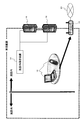
- FIG. 1 shows a device configuration example of a communication system according to the present invention.
- the communication system includes an access point 10, a communication terminal 12, an in-facility communication device 14, a user location authentication server 16, and a connection information providing server 18.
- the access point 10 is a wireless communication base station for connecting to the Internet 20, and is provided in a restaurant or other predetermined facility.
- the access point 10 performs wireless communication with a communication terminal 12 having a wireless communication function such as a portable terminal or a personal computer in a facility, and a connection service (public wireless LAN) between the communication terminal 12 and the Internet 20. Service).
- Examples of the mobile terminal include a mobile phone terminal and a personal digital assistant (PDA).
- PDA personal digital assistant
- the personal computer is equipped with a communication card for performing wireless communication.
- the range (reception range) in which the communication terminal 12 can receive the radio waves of the access point 10 is determined by the function of the access point 10, but the reception range usually does not fit within the facility. That is, as indicated by a broken line in FIG. 1, the reception range partially reaches outside the facility.
- the access point 10 may be an ultra-small base station device that covers an area called a “femtocell” having a radius of several tens of meters.
- the in-facility communication device 14 is also installed in the facility, wirelessly communicates with the communication terminal 12, and notifies the user position authentication server 16 of the communication result.
- the user location authentication server 16 operates on an appropriate computer, receives the communication result from the in-facility communication device 14, determines whether the communication terminal 12 exists in the facility, and performs a predetermined authentication process. Do. Details of the authentication process will be described later.
- the connection information providing server 18 also operates on an appropriate computer, and connects to the access point 10 to the communication terminal 12 via the in-facility communication device 14 according to the result of the authentication processing of the user location authentication server 16. Provide the connection information necessary for.
- This connection information includes, for example, the SSID of the access point 10, encryption information, and the like.
- the encryption information may be configured such that the encryption key is changed at predetermined time intervals or when access to the access point 10 is lost.
- the connection information providing server 18 may operate on the same computer as the user location authentication server 16 or may operate on a different computer.
- the in-facility communication device 14 uses an ultra wideband (UWB) UWB wireless communication device 14a.
- UWB ultra wideband
- distance measurement can also be performed.
- a plurality of UWB wireless communication devices 14a are installed as a base station, and the base station and the communication terminal 12 are based on the difference in communication time (radio wave arrival time) between each base station and the communication terminal 12. It measures the distance to. For this reason, distance information between the communication terminal 12 and the UWB wireless communication device 14a can be transmitted to the user location authentication server 16 as the communication result.
- the user location authentication server 16 can calculate the location information of the communication terminal 12 from the distance information.
- the position information is information regarding whether or not the communication terminal 12 exists in a predetermined facility, including the direction and distance from the wall of the facility, for example. If the user location authentication server 16 has the location information of the wall of the facility as authentication information in advance, the location information of the communication terminal 12 is compared to determine whether the communication terminal 12 exists in the facility. Can be determined.
- a short-range wireless communication device such as a wireless LAN device or Bluetooth (registered trademark) may be used.
- radio waves transmitted from the communication terminal 12 are received by a plurality of wireless LAN access points or short-range wireless communication devices installed as base stations, and the communication time between each base station and the communication terminal 12 ( The distance between the base station and the communication terminal 12 can be measured based on the difference in radio wave arrival time, radio wave phase difference, radio wave attenuation, and the like.
- the visible light communication device 14 b is used as the in-facility communication device 14.
- the visible light communication device 14b uses, for example, light from a lighting device such as a fluorescent lamp provided on the ceiling of a facility or a light emitting diode (LED) provided separately from the lighting device to human eyes. Communication is performed by blinking at a period that is not felt by the user.
- the connection information providing server 18 transmits connection information necessary for connection with the access point 10 by flashing light through the visible light communication device 14b.
- connection information can be received, that is, only the communication terminal 12 existing in the facility can connect to the Internet 20 via the access point 10.
- the user location authentication server 16 can be dispensed with.
- the user location authentication server 16 may determine whether or not the communication terminal 12 exists in the facility depending on whether or not the visible light communication between the visible light communication device 14b and the communication terminal 12 is possible.
- the in-facility communication device 14 a reader and writer for non-contact IC cards such as FeliCa (registered trademark) and NFC may be used.
- the connection information providing server 18 provides connection information necessary for connection to the access point 10 to the communication terminal 12 via the writer.
- the user location authentication server 16 can be omitted.
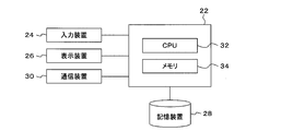
- FIG. 3 shows an example of a hardware configuration of a computer that operates the user location authentication server 16 and the connection information providing server 18.
- the computer includes a processing unit 22, an input device 24, a display device 26, a storage device 28, and a communication device 30.
- the processing unit 22 includes a central processing unit (for example, a CPU can be used) 32, a memory 34, and the like.
- the processing unit 22 executes a program for controlling the processing operation of the CPU 32 to realize each function described later.
- the input device 24 includes a keyboard and a pointing device, and is used by a user to input operation instructions and the like.
- the display device 26 is configured by a liquid crystal display (LCD) or a CRT (Cathode Ray Tube), and displays information necessary for controlling the communication system.
- LCD liquid crystal display
- CRT Cathode Ray Tube
- the input device 24 and the display device 26 may be omitted depending on the operation status of the user location authentication server 16 and the connection information providing server 18.
- the storage device 28 is constituted by a hard disk device (HDD) device or the like, and stores a program for controlling the processing operation of the CPU 32 and other information necessary for controlling the communication system.
- HDD hard disk device
- the communication device 30 is configured by an appropriate communication interface such as a network card, and is used by the processing unit 22 to exchange data with an external device via communication means such as a network.
- FIG. 4 shows a functional block diagram of an embodiment of a communication system according to the present invention.
- the communication system includes the functions of the access point 10, the position information acquisition unit 36, the authentication processing unit 38, and the connection information providing unit 40.
- the access point 10 is as described in FIG.
- the functions of the position information acquisition unit 36, the authentication processing unit 38, and the connection information providing unit 40 are realized by the CPU 32 and a program that controls the processing operation of the CPU 32.
- the location information acquisition unit 36 is realized in the user location authentication server 16, receives a communication result with the communication terminal 12 from the in-facility communication device 14 via the communication device 30, and whether the communication terminal 12 exists in a predetermined facility.
- the position information which is information regarding whether or not is acquired.
- the communication result received from the UWB wireless communication device 14a includes distance information between the communication terminal 12 and the UWB wireless communication device 14a. Therefore, the position information acquisition unit 36 calculates the position information of the communication terminal 12 from the distance information. If the location information of the facility wall is stored as authentication information in the storage device 28 or the like in advance, the location information acquisition unit 36 compares the location information of the communication terminal 12 with the location information of the facility wall, and the communication terminal 12 Can be determined in the facility.
- the position information acquisition unit 36 can determine whether or not the communication terminal 12 exists in the facility in the same manner as when the UWB wireless communication device 14a is used.
- the user location authentication server 16 can be dispensed with as described above, so that the location information acquisition unit realized on the user location authentication server 16 36 can also be omitted.
- the communication terminal 12 and the visible light communication device 14b can communicate with each other, the position information is acquired when visible light communication is possible between the visible light communication device 14b and the communication terminal 12.
- the unit 36 can acquire the position information that the communication terminal 12 exists in the facility.
- the position information acquisition unit 36 can acquire position information from the reader. That is, since the leader is installed in the facility, the communication terminal 12 in the vicinity of the leader exists in the facility. Therefore, the position information acquisition unit 36 can acquire position information that the communication terminal 12 close to the reader exists in the facility.
- the devices used by the position information acquisition unit 36 to acquire position information include the UWB wireless communication device 14a, visible light communication device 14b, wireless LAN device, short-range wireless communication device, and contactless IC card. Any means / device having a function of acquiring position information can be used without being limited to the reader.
- the authentication processing unit 38 is also realized in the user location authentication server 16 and performs authentication processing of the communication terminal 12 based on the location information acquired by the location information acquisition unit 36. In this authentication process, if the communication terminal 12 is present in the facility as the location information, the authentication is successful, and if the communication terminal 12 is not present in the facility, the authentication fails. And When the result of the authentication processing is successful, the authentication processing unit 38 notifies the connection information providing unit 40 of the authentication result. As described above, in the configuration in which the user location authentication server 16 can be omitted, the authentication processing unit 38 can also be omitted.
- connection information providing unit 40 is realized in the connection information providing server 18.
- the connection information providing unit 40 When receiving a notification of successful authentication from the authentication processing unit 38, the connection information providing unit 40 is connected to the communication terminal 12 via the communication device 30 and the in-facility communication device 14. 10 provides connection information necessary for connection with the terminal 10.
- the connection information providing unit 40 provides the connection information to the communication terminal 12 that can communicate with the in-facility communication device 14 via the in-facility communication device 14.
- the UWB wireless communication device 14a, the visible light communication device 14b, the short-range wireless communication device, the lighter for the non-contact IC card, etc. are used as the in-facility communication device 14.
- the in-facility communication device 14 used by the connection information providing unit 40 to provide connection information is not limited to these, and all means and devices having a function for communicating with the communication terminal 12 are used. be able to.
- the communication terminal 12 provided with the connection information from the connection information providing unit 40 sets the connection information and connects to the Internet 20 via the access point 10.
- the connection information may be set manually by the user, or may be automatically set by an appropriate program.
- the communication terminal 12 is a personal computer
- communication with the in-facility communication device 14 is performed by a portable terminal
- connection information provided by the portable terminal is personalized by short-range wireless communication such as Bluetooth (registered trademark). It is good also as a structure provided to a computer.
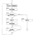
- FIG. 5 shows a flow of an operation example of the communication system according to the present invention.
- the position information acquisition unit 36 analyzes the distance information included in the communication result with the communication terminal 12 received from the in-facility communication device 14, and whether or not the communication terminal 12 exists in the predetermined facility.
- Position information which is information relating to the above, is acquired (S101).
- the authentication processing unit 38 starts the authentication process of the communication terminal 12 based on the position information acquired by the position information acquiring unit 36 (S102).
- the authentication processing unit 38 confirms whether or not the communication terminal 12 is present in the facility as the position information (S103). (S104).
- the result of successful authentication is notified to the connection information providing unit 40.
- the connection information providing unit 40 provides the communication terminal 12 with connection information necessary for connection with the access point 10 via the in-facility communication device 14 (S105).
- FIG. 6 shows a flow of another operation example of the communication system according to the present invention.
- the steps from S201 to S206 are the same as the steps from S101 to S106 in FIG.
- WPA WPA or the like is used as the encryption information
- the access point 10 itself or the connection information providing unit 40 changes the encryption key of the encryption information.
- the encryption key can be changed at an appropriate timing such as every predetermined time or when access from the communication terminal 12 to the access point 10 is lost.
- the authentication processing unit 38 monitors whether or not the encryption key of the encryption information included in the connection information has been changed (S207). If the encryption key has been changed, the steps from S201 are repeated. Thereby, the acquisition and authentication processing of the position information is performed again, and the connection information providing unit 40 provides the connection information including the changed encryption key to the communication terminal that has been successfully authenticated.
- the connection to the access point 10 can be refused when the communication terminal 12 existing in the facility at one time is subsequently moved out of the facility. Thereby, the communication terminals 12 that exist in the facility and can be connected to the access point 10 can be more precisely selected.
Abstract
飲食店等の所定の施設内に存在する通信端末のみをインターネットに接続可能な通信システムであって、ユーザ位置認証サーバ16が、施設内通信装置14から受け取った通信端末12との通信結果に含まれる距離情報等を解析して、通信端末12が所定の施設内に存在するか否かを判定し、通信端末12が施設内に存在していると判定された場合に認証成功とする。接続情報提供部40は、上記認証が成功した場合に、通信端末12に施設内通信装置14を介してアクセスポイント10との接続に必要な接続情報を提供する。これにより、施設内に存在する通信端末12のみがアクセスポイント10を介してインターネットに接続することができる。
Description
本発明は、通信端末が所定の施設内に存在するときにネットワークを介した通信を可能とする通信システムに関する。
近年、無線LAN(Local Area Network)のアクセスポイントを介して、不特定多数の通信端末をインターネットに接続する、いわゆる公衆無線LANサービスが実用化されている。このような公衆無線LANサービスにおけるセキュリティ対策として、例えばアクセスポイントのSSID(Service Set Identifier)を隠蔽し、アクセスポイントの存在を隠す、通信端末とアクセスポイントとの通信を暗号化する、認証処理によりアクセスポイントに接続できる通信端末を制限すること等が行われている。
例えば、下記特許文献1には、無線LANアクセスポイントと接続されるIP電話端末の認証処理に関する技術が開示されている。
特開2007-221481号公報
ところで、公衆無線LANサービスを喫茶店やファストフード等の飲食店で行う場合、不特定の来店者に対して公衆無線LANサービスを提供するためには、上記セキュリティ対策を実施することが困難である。この場合、アクセスポイントの電波が受信できる範囲であれば店外の通信端末でも公衆無線LANサービスを享受でき、来店者のみに公衆無線LANサービスを限定することができない。
また、公衆無線LANプロバイダのサービスを利用し、店内に当該プロバイダのアクセスポイントを設置すれば、プロバイダの利用登録者のみに公衆無線LANサービスの対象者を限定できるが、上記利用登録者が店外にいても、アクセスポイントの電波が受信できる範囲であれば公衆無線LANサービスを享受することができる。従って、この場合も来店者のみに公衆無線LANサービスを限定することができない。
本発明は、上記従来の課題に鑑みなされたものであり、その目的は、飲食店等の所定の施設内に存在する通信端末のみをインターネットに接続可能な通信システムを提供することにある。
上記目的を達成するために、請求項1記載の通信システムの発明は、無線通信機能を有する通信端末とネットワークとを接続する、無線通信の基地局としてのアクセスポイントと、前記通信端末が所定の施設内に存在するか否かに関する情報である位置情報を取得する位置情報取得手段と、前記位置情報に基づいて、前記通信端末の認証処理を行う認証処理手段と、前記認証処理手段による前記通信端末の認証が成功した場合に、前記通信端末に前記アクセスポイントとの接続に必要な接続情報を提供する接続情報提供手段と、を備えることを特徴とする。
請求項2記載の発明は、請求項1記載の通信システムにおいて、前記接続情報に含まれる暗号情報が所定の時間毎に変更され、前記認証処理手段は、前記暗号情報が変更されると前記通信端末の認証処理を行い、前記接続情報提供手段は、前記認証が成功した通信端末に、変更後の暗号情報が含まれる接続情報を提供することを特徴とする。
請求項3記載の発明は、請求項1記載の通信システムにおいて、前記接続情報に含まれる暗号情報が、前記通信端末から前記アクセスポイントへのアクセスが無くなったときに変更され、前記認証処理手段は、前記暗号情報が変更されると前記通信端末の認証処理を行い、前記接続情報提供手段は、前記認証が成功した通信端末に、変更後の暗号情報が含まれる接続情報を提供することを特徴とする。
請求項4記載の発明は、請求項1から請求項3のいずれか一項記載の通信システムにおいて、前記位置情報取得手段が、超広帯域無線(UWB)装置、可視光通信装置、無線LAN装置、短距離無線通信装置または非接触ICカードのリーダーのいずれかを使用することを特徴とする。
請求項5記載の発明は、請求項1から請求項4のいずれか一項記載の通信システムにおいて、前記接続情報提供手段が、超広帯域無線装置、可視光通信装置、短距離無線通信装置または非接触ICカードのライターのいずれかを使用することを特徴とする。
請求項6記載の通信システムの発明は、無線通信機能を有する通信端末とネットワークとを接続する、無線通信の基地局としてのアクセスポイントと、前記通信端末が所定の施設内に存在する場合に、前記通信端末に前記アクセスポイントとの接続に必要な接続情報を提供する接続情報提供手段と、を備えることを特徴とする。
請求項7記載の発明は、請求項6記載の通信システムにおいて、前記接続情報提供手段が可視光通信装置を使用し、前記可視光通信装置と通信可能な前記通信端末に前記アクセスポイントとの接続に必要な接続情報を提供することを特徴とする。
請求項8記載の発明は、請求項6記載の通信システムにおいて、前記接続情報提供手段が非接触ICカードのリーダー及びライターを使用し、前記リーダー及びライターに近接した前記通信端末に前記アクセスポイントとの接続に必要な接続情報を提供することを特徴とする。
請求項9記載の発明は、請求項1から請求項8のいずれか一項記載の通信システムにおいて、前記通信端末が携帯電話端末であることを特徴とする。
請求項10記載の発明は、請求項1から請求項8のいずれか一項記載の通信システムにおいて、前記通信端末が携帯電話端末であり、前記携帯電話端末は、短距離無線通信により前記接続情報をパーソナルコンピュータに提供し、前記アクセスポイントは、前記パーソナルコンピュータとネットワークとを接続することを特徴とする。
請求項1、請求項4及び請求項5の発明によれば、所定の施設内に存在する通信端末のみにアクセスポイントとの接続に必要な接続情報を提供し、インターネットに接続可能とすることができる。
また、請求項2及び請求項3の発明によれば、暗号情報の変更により、アクセスポイントへ接続可能な通信端末を、より精密に選別することができる。
請求項6から請求項8の発明によれば、より簡易な構成により施設内に存在する通信端末を選別することができる。
請求項9及び請求項10の発明によれば、携帯電話端末の利用により、より利便性の高い通信システムを提供できる。
10 アクセスポイント、12 通信端末、14 施設内通信装置、14a UWB無線通信装置、14b 可視光通信装置、16 ユーザ位置認証サーバ、18 接続情報提供サーバ、20 インターネット、22 処理部、24 入力装置、26 表示装置、28 記憶装置、30 通信装置、32 CPU、34 メモリ、36 位置情報取得部、38 認証処理部、40 接続情報提供部。
以下、本発明を実施するための最良の形態(以下、実施形態という)を、図面に従って説明する。
図1には、本発明にかかる通信システムの装置構成例が示される。図1において、通信システムは、アクセスポイント10、通信端末12、施設内通信装置14、ユーザ位置認証サーバ16及び接続情報提供サーバ18を含んで構成されている。
アクセスポイント10は、インターネット20に接続するための無線通信の基地局であり、飲食店その他の所定の施設内に設けられている。このアクセスポイント10は、施設内にある携帯端末、パーソナルコンピュータ等の無線通信機能を有する通信端末12との間で無線通信を行い、これらの通信端末12とインターネット20との接続サービス(公衆無線LANサービス)を提供している。上記携帯端末としては、例えば携帯電話端末あるいは携帯情報端末(PDA)等があげられる。また、パーソナルコンピュータには、無線通信を行うための通信用カードが装着されている。
ここで、上記通信端末12がアクセスポイント10の電波を受信できる範囲(受信範囲)はアクセスポイント10の機能により決まるが、通常は上記施設内に受信範囲が収まることはない。すなわち、図1に破線で示されるように、受信範囲が一部施設外まで達している。なお、上記アクセスポイント10は、「フェムトセル」と呼ばれる半径数十メートルのエリアを対象とする超小型基地局装置であってもよい。
また、施設内通信装置14も上記施設内に設置されており、上記通信端末12と無線通信し、通信結果をユーザ位置認証サーバ16に通知する。
ユーザ位置認証サーバ16は、適宜なコンピュータ上で動作し、施設内通信装置14から上記通信結果を受信して通信端末12が上記施設内に存在するか否かを判定し、所定の認証処理を行う。認証処理の詳細については後述する。また、接続情報提供サーバ18も適宜なコンピュータ上で動作し、ユーザ位置認証サーバ16の認証処理の結果に応じて、施設内通信装置14を介して通信端末12に対し、アクセスポイント10との接続に必要な接続情報を提供する。この接続情報には、例えばアクセスポイント10のSSID,暗号情報等が含まれる。暗号情報は、所定の時間毎またはアクセスポイント10へのアクセスが無くなったとき等のタイミングで暗号鍵を変更する構成としてもよい。なお、接続情報提供サーバ18は、ユーザ位置認証サーバ16と同一のコンピュータ上で動作してもよく、また異なるコンピュータ上で動作してもよい。
図2(a),(b)には、施設内通信装置14の構成例が示される。図2(a)において、施設内通信装置14には、超広帯域無線(UWB)方式のUWB無線通信装置14aが使用されている。超広帯域無線方式では、情報の送受信に加えて、距離測定も行うことができる。この距離測定は、例えばUWB無線通信装置14aを基地局として複数台設置し、それぞれの基地局と通信端末12との通信時間(電波の到達時間)の差等に基づいて基地局と通信端末12との距離を測定するものである。このため、ユーザ位置認証サーバ16に対して、上記通信結果として通信端末12とUWB無線通信装置14aとの距離情報を送信することができる。ユーザ位置認証サーバ16はその距離情報から通信端末12の位置情報を計算することができる。ここで、位置情報は、例えば施設の壁からの方向及び距離を含み、通信端末12が所定の施設内に存在するか否かに関する情報である。ユーザ位置認証サーバ16が、施設の壁の位置情報を予め認証情報として有していれば、通信端末12の位置情報と比較することにより、当該通信端末12が施設内に存在するか否かを判定することができる。
なお、施設内通信装置14としては、無線LAN装置あるいはブルートゥース(Bluetooth 登録商標)等の短距離無線通信装置を使用することもできる。この場合、例えば通信端末12から発信される電波を、基地局として複数台設置された無線LANのアクセスポイントまたは短距離無線通信装置で受信し、それぞれの基地局と通信端末12との通信時間(電波の到達時間)の差、電波の位相差、電波減衰量等に基づいて基地局と通信端末12との距離を測定することができる。
また、図2(b)では、施設内通信装置14として可視光通信装置14bが使用されている。本実施形態の場合、可視光通信装置14bは、例えば施設の天井等に設けられた蛍光灯等の照明装置または照明装置とは別に設けられた発光ダイオード(LED)等の光を、人間の目に感じない程度の周期で点滅させて通信を行う。ここで、可視光が施設の外に漏洩しないように構成すれば、可視光通信装置14bから信号を受信できる通信端末12は、施設内に存在することになる。そこで、図2(b)の実施形態では、接続情報提供サーバ18が可視光通信装置14bを介して光の点滅によりアクセスポイント10との接続に必要な接続情報を送信する。これにより、接続情報を受信できた、すなわち施設内に存在する通信端末12のみがアクセスポイント10を介してインターネット20に接続することができる。この場合、上記接続情報を受信できることが施設内に存在してることを意味するので、ユーザ位置認証サーバ16は不要とすることができる。なお、通信端末12からも通信用の可視光を出射できる構成としておけば、可視光通信装置14bとの間で相互通信ができる。従って、可視光通信装置14bと通信端末12との間の可視光通信の可否によりユーザ位置認証サーバ16に通信端末12が施設内に存在しているか否かを判定させてもよい。
また、施設内通信装置14として、フェリカ(FeliCa 登録商標),NFC等の非接触ICカード用のリーダー及びライターを使用してもよい。この場合、上記リーダー及びライターは施設内に設置されているので、これに近接した通信端末12は施設内に存在していることを意味する。従って、接続情報提供サーバ18は、上記ライターを介して通信端末12にアクセスポイント10との接続に必要な接続情報を提供する。なお、この場合には、ユーザ位置認証サーバ16は不要とすることができる。また、上記リーダーに近接した通信端末12は施設内に存在しているとユーザ位置認証サーバ16が判定する構成としてもよい。
図3には、上記ユーザ位置認証サーバ16及び接続情報提供サーバ18を動作させるコンピュータのハードウェア構成の例が示される。図3において、コンピュータは、処理部22、入力装置24、表示装置26、記憶装置28及び通信装置30を含んで構成されている。
処理部22は、中央処理装置(例えばCPUを使用することができる)32及びメモリ34等を含んで構成され、CPU32の処理動作を制御するプログラムを実行して後述する各機能を実現する。
入力装置24は、キーボード及びポインティングデバイス等を含んで構成され、利用者が動作指示等を入力するために使用する。
表示装置26は、液晶ディスプレイ(LCD)あるいはCRT(Cathode Ray Tube)等により構成され、通信システムの制御に必要な情報等を表示する。
なお、上記入力装置24及び表示装置26は、ユーザ位置認証サーバ16及び接続情報提供サーバ18の運用状況に応じて省略することもできる。
記憶装置28は、ハードディスク装置(HDD)装置等により構成され、上記CPU32の処理動作を制御するプログラムその他の通信システムの制御に必要な情報等を格納する。
通信装置30は、ネットワークカード等の適宜な通信インターフェースにより構成され、処理部22がネットワーク等の通信手段を介して外部の装置とデータをやり取りするために使用する。
図4には、本発明にかかる通信システムの一実施形態の機能ブロック図が示される。図4において、通信システムは、アクセスポイント10、位置情報取得部36、認証処理部38及び接続情報提供部40の各機能を含んで構成されている。これらのうち、アクセスポイント10は、図1で説明した通りである。また、位置情報取得部36、認証処理部38及び接続情報提供部40の機能はCPU32及びCPU32の処理動作を制御するプログラムにより実現される。
位置情報取得部36は、ユーザ位置認証サーバ16において実現され、通信装置30を介して施設内通信装置14から通信端末12との通信結果を受け取り、通信端末12が所定の施設内に存在するか否かに関する情報である位置情報を取得する。施設内通信装置14として上述したUWB無線通信装置14aを使用した場合には、UWB無線通信装置14aから受け取る通信結果に、通信端末12とUWB無線通信装置14aとの距離情報が含まれる。そこで、位置情報取得部36は、上記距離情報から通信端末12の位置情報を計算する。記憶装置28等に、施設の壁の位置情報を予め認証情報として格納しておけば、位置情報取得部36は、通信端末12の位置情報と施設の壁の位置情報を比較し、通信端末12が施設内に存在するか否かを判定することができる。
また、施設内通信装置14として上述した無線LAN装置あるいは短距離無線通信装置を使用した場合にも、施設内通信装置14から受け取る通信結果に、通信端末12と施設内通信装置14との距離情報を含ませることができる。従って、この場合にも位置情報取得部36は、UWB無線通信装置14aを使用する場合と同様にして、通信端末12が施設内に存在するか否かを判定することができる。
また、施設内通信装置14として可視光通信装置14bを使用した場合には、上述したように、ユーザ位置認証サーバ16を不要とできるので、ユーザ位置認証サーバ16上で実現される位置情報取得部36も省略することができる。ただし、通信端末12と可視光通信装置14bとの間で相互通信ができる構成の場合には、可視光通信装置14bと通信端末12との間の可視光通信が可能なときに、位置情報取得部36が施設内に通信端末12が存在しているとの位置情報を取得することができる。
さらに、施設内通信装置14としてNFC等の非接触ICカード用のリーダー及びライターを使用した場合には、位置情報取得部36は、そのリーダーから位置情報を取得することができる。すなわち、上記リーダーは施設内に設置されているので、これに近接した通信端末12は施設内に存在していることになる。そこで、位置情報取得部36は、リーダーに近接した通信端末12が施設内に存在しているとの位置情報を取得することができる。
なお、位置情報取得部36が位置情報を取得するために使用する装置としては、上記UWB無線通信装置14a、可視光通信装置14b、無線LAN装置、短距離無線通信装置、非接触ICカード用のリーダーに限定されず、位置情報を取得する機能を有する全ての手段・装置を使用することができる。
認証処理部38もユーザ位置認証サーバ16において実現され、上記位置情報取得部36が取得した位置情報に基づいて通信端末12の認証処理を行う。この認証処理では、上記位置情報として通信端末12が施設内に存在しているとされている場合に認証成功とし、通信端末12が施設内に存在していないとされている場合には認証失敗とする。認証処理の結果が認証成功の場合には、認証処理部38から接続情報提供部40に認証結果が通知される。なお、上述したように、ユーザ位置認証サーバ16を不要とできる構成では、認証処理部38も省略することができる。
接続情報提供部40は、接続情報提供サーバ18において実現され、上記認証処理部38から認証成功の通知を受け取った場合に、通信端末12に通信装置30及び施設内通信装置14を介してアクセスポイント10との接続に必要な接続情報を提供する。なお、ユーザ位置認証サーバ16を不要とできる構成では、接続情報提供部40が施設内通信装置14と通信可能な通信端末12に施設内通信装置14を介して接続情報を提供する構成とする。
この場合に施設内通信装置14として使用されるものとしては、上述したUWB無線通信装置14a、可視光通信装置14b、短距離無線通信装置、非接触ICカード用のライター等がある。ただし、接続情報提供部40が接続情報を提供するために使用する施設内通信装置14としては、これらに限定されず、通信端末12と通信するための機能を有する全ての手段・装置を使用することができる。
接続情報提供部40から接続情報を提供された通信端末12は、その接続情報を設定し、アクセスポイント10を介してインターネット20に接続する。上記接続情報の設定は、利用者が手動で行ってもよいし、適宜なプログラムにより自動設定としてもよい。なお、通信端末12がパーソナルコンピュータである場合において、施設内通信装置14との通信を携帯端末で行い、携帯端末が提供された接続情報をブルートゥース(Bluetooth 登録商標)等の短距離無線通信によりパーソナルコンピュータに提供する構成としてもよい。
図5には、本発明にかかる通信システムの動作例のフローが示される。図5において、位置情報取得部36が、施設内通信装置14から受け取った通信端末12との通信結果に含まれる距離情報等を解析して、通信端末12が所定の施設内に存在するか否かに関する情報である位置情報を取得する(S101)。
認証処理部38は、位置情報取得部36が取得した位置情報に基づいて通信端末12の認証処理を開始する(S102)。認証処理部38は、上記位置情報として通信端末12が施設内に存在しているとされているか否かを確認し(S103)、施設内に存在しているとされている場合に認証成功とする(S104)。認証成功の結果は、接続情報提供部40に通知される。この場合、接続情報提供部40は、通信端末12に施設内通信装置14を介してアクセスポイント10との接続に必要な接続情報を提供する(S105)。
一方、S103において、通信端末12が施設内に存在していないとされている場合には、認証失敗とし(S106)、処理を終了する。
図6には、本発明にかかる通信システムの他の動作例のフローが示される。図6において、S201からS206までのステップは、図5におけるS101からS106までのステップと共通であるので、説明を省略する。
本実施形態においては、暗号情報として例えばWPA等を使用し、アクセスポイント10自身で、あるいは接続情報提供部40が暗号情報の暗号鍵を変更する構成とする。なお、暗号鍵の変更は、例えば所定時間毎、あるいは通信端末12からアクセスポイント10へのアクセスが無くなったとき等の適宜なタイミングとすることができる。
S205において通信端末12に接続情報を提供された後、認証処理部38は、接続情報に含まれる暗号情報の暗号鍵が変更されたか否かを監視する(S207)。暗号鍵が変更された場合には、S201からのステップを繰り返す。これにより、位置情報の取得、認証処理が再度行われ、認証が成功した通信端末に、接続情報提供部40が変更後の暗号鍵が含まれる接続情報を提供する。
本実施形態では、所定のタイミングで暗号鍵が変更されるので、あるときに施設内に存在した通信端末12が、その後施設外に移動された場合に、アクセスポイント10への接続を拒否できる。これにより、施設内に存在し、アクセスポイント10へ接続可能な通信端末12を、より精密に選別することができる。
以上、本発明の実施形態をいくつか紹介したが、本発明は上記実施形態に限定されるものではない。
Claims (10)
- 無線通信機能を有する通信端末とネットワークとを接続する、無線通信の基地局としてのアクセスポイントと、
前記通信端末が所定の施設内に存在するか否かに関する情報である位置情報を取得する位置情報取得手段と、
前記位置情報に基づいて、前記通信端末の認証処理を行う認証処理手段と、
前記認証処理手段による前記通信端末の認証が成功した場合に、前記通信端末に前記アクセスポイントとの接続に必要な接続情報を提供する接続情報提供手段と、
を備えることを特徴とする通信システム。 - 請求項1記載の通信システムにおいて、前記接続情報に含まれる暗号情報が所定の時間毎に変更され、前記認証処理手段は、前記暗号情報が変更されると前記通信端末の認証処理を行い、前記接続情報提供手段は、前記認証が成功した通信端末に、変更後の暗号情報が含まれる接続情報を提供することを特徴とする通信システム。
- 請求項1記載の通信システムにおいて、前記接続情報に含まれる暗号情報が、前記通信端末から前記アクセスポイントへのアクセスが無くなったときに変更され、前記認証処理手段は、前記暗号情報が変更されると前記通信端末の認証処理を行い、前記接続情報提供手段は、前記認証が成功した通信端末に、変更後の暗号情報が含まれる接続情報を提供することを特徴とする通信システム。
- 請求項1から請求項3のいずれか一項記載の通信システムにおいて、前記位置情報取得手段は、超広帯域無線装置、可視光通信装置、無線LAN装置、短距離無線通信装置または非接触ICカードのリーダーのいずれかを使用することを特徴とする通信システム。
- 請求項1から請求項4のいずれか一項記載の通信システムにおいて、前記接続情報提供手段は、超広帯域無線装置、可視光通信装置、短距離無線通信装置または非接触ICカードのライターのいずれかを使用することを特徴とする通信システム。
- 無線通信機能を有する通信端末とネットワークとを接続する、無線通信の基地局としてのアクセスポイントと、
前記通信端末が所定の施設内に存在する場合に、前記通信端末に前記アクセスポイントとの接続に必要な接続情報を提供する接続情報提供手段と、
を備えることを特徴とする通信システム。 - 請求項6記載の通信システムにおいて、前記接続情報提供手段が可視光通信装置を使用し、前記可視光通信装置と通信可能な前記通信端末に前記アクセスポイントとの接続に必要な接続情報を提供することを特徴とする通信システム。
- 請求項6記載の通信システムにおいて、前記接続情報提供手段は、非接触ICカードのリーダー及びライターを使用し、前記リーダー及びライターに近接した前記通信端末に前記アクセスポイントとの接続に必要な接続情報を提供することを特徴とする通信システム。
- 請求項1から請求項8のいずれか一項記載の通信システムにおいて、前記通信端末は、携帯電話端末であることを特徴とする通信システム。
- 請求項1から請求項8のいずれか一項記載の通信システムにおいて、前記通信端末は、携帯電話端末であり、前記携帯電話端末は、短距離無線通信により前記接続情報をパーソナルコンピュータに提供し、前記アクセスポイントは、前記パーソナルコンピュータとネットワークとを接続することを特徴とする通信システム。
Applications Claiming Priority (2)
| Application Number | Priority Date | Filing Date | Title |
|---|---|---|---|
| JP2008017266A JP2009182391A (ja) | 2008-01-29 | 2008-01-29 | 通信システム |
| JP2008-017266 | 2008-01-29 |
Publications (1)
| Publication Number | Publication Date |
|---|---|
| WO2009096184A1 true WO2009096184A1 (ja) | 2009-08-06 |
Family
ID=40912539
Family Applications (1)
| Application Number | Title | Priority Date | Filing Date |
|---|---|---|---|
| PCT/JP2009/000344 WO2009096184A1 (ja) | 2008-01-29 | 2009-01-29 | 通信システム |
Country Status (2)
| Country | Link |
|---|---|
| JP (1) | JP2009182391A (ja) |
| WO (1) | WO2009096184A1 (ja) |
Cited By (6)
| Publication number | Priority date | Publication date | Assignee | Title |
|---|---|---|---|---|
| DE202012003802U1 (de) | 2012-03-28 | 2013-04-02 | BLüCHER GMBH | Adsorptives Filtermedium |
| DE202013003676U1 (de) | 2013-03-15 | 2014-03-19 | BLüCHER GMBH | Neue Konzepte für die Wasserbehandlung, insbesondere Wasseraufbereitung und/oder -aufreinigung |
| DE202015104218U1 (de) | 2015-07-25 | 2016-07-26 | BLüCHER GMBH | Neuartiges textiles Schutzmaterial |
| DE202016100020U1 (de) | 2015-11-30 | 2016-12-01 | BLüCHER GMBH | Funktionelle Fußbekleidungseinheit |
| DE202018100242U1 (de) | 2017-11-28 | 2018-12-07 | BLüCHER GMBH | Luftdurchlässiges Flächenfiltermaterial |
| WO2022244704A1 (ja) * | 2021-05-20 | 2022-11-24 | LocationMind株式会社 | 屋内位置認証方法、屋内位置認証システム、及び屋内位置認証装置 |
Families Citing this family (10)
| Publication number | Priority date | Publication date | Assignee | Title |
|---|---|---|---|---|
| JP5725532B2 (ja) * | 2010-09-24 | 2015-05-27 | 日本電気通信システム株式会社 | 無線通信装置、無線通信システム及び無線通信方法 |
| KR101341256B1 (ko) * | 2011-09-19 | 2013-12-12 | 주식회사 팬택 | 네트워크의 접속 보안 강화 장치 및 방법 |
| JP6347107B2 (ja) * | 2013-01-18 | 2018-06-27 | 株式会社リコー | 通信管理システム、通信制御システム、通信システム、中継装置、通信方法、及びプログラム |
| JP6294814B2 (ja) * | 2014-11-18 | 2018-03-14 | 日本電信電話株式会社 | 無線通信方法、無線通信システム、無線通信装置、およびプログラム |
| JP6294815B2 (ja) * | 2014-11-18 | 2018-03-14 | 日本電信電話株式会社 | 無線通信方法、無線通信システム、無線通信装置、およびプログラム |
| JP6728723B2 (ja) * | 2015-03-12 | 2020-07-22 | 株式会社リコー | 通信装置、通信システム、プログラム及び通信制御方法 |
| CN106330843B (zh) * | 2015-07-02 | 2020-01-14 | 株式会社理光 | 用于区域受限访问的系统和方法 |
| JP6512982B2 (ja) * | 2015-07-30 | 2019-05-15 | キヤノン株式会社 | 通信装置、通信装置の制御方法及びプログラム |
| US10051003B2 (en) | 2015-07-30 | 2018-08-14 | Apple Inc. | Privacy enhancements for wireless devices |
| JP6404274B2 (ja) * | 2016-06-24 | 2018-10-10 | コグニティブリサーチラボ株式会社 | 位置情報を利用した通信セキュリティシステム |
Citations (7)
| Publication number | Priority date | Publication date | Assignee | Title |
|---|---|---|---|---|
| JP2002351766A (ja) * | 2001-05-29 | 2002-12-06 | Denso Corp | 設定ファイル送信システムおよび設定ファイルの送信方法 |
| WO2003047173A1 (fr) * | 2001-11-27 | 2003-06-05 | Sony Corporation | Dispositif et procede de communication |
| JP2005065018A (ja) * | 2003-08-18 | 2005-03-10 | Nec Corp | 無線lan接続システム、無線lan接続方法及び無線端末 |
| JP2005341254A (ja) * | 2004-05-27 | 2005-12-08 | Denso Corp | 車載用無線lan接続端末 |
| JP2006238343A (ja) * | 2005-02-28 | 2006-09-07 | Nec Commun Syst Ltd | 暗号キー配信装置、無線通信端末、無線アクセスポイント、無線データ通信システム、無線データ通信方法、プログラム、記録媒体 |
| JP2007150984A (ja) * | 2005-11-30 | 2007-06-14 | Sony Corp | 無線通信システム,通信装置,設定情報提供方法,設定情報取得方法,およびコンピュータプログラム |
| JP2007336010A (ja) * | 2006-06-12 | 2007-12-27 | Canon Inc | 通信装置およびその方法 |
Family Cites Families (1)
| Publication number | Priority date | Publication date | Assignee | Title |
|---|---|---|---|---|
| US7042867B2 (en) * | 2002-07-29 | 2006-05-09 | Meshnetworks, Inc. | System and method for determining physical location of a node in a wireless network during an authentication check of the node |
-
2008
- 2008-01-29 JP JP2008017266A patent/JP2009182391A/ja active Pending
-
2009
- 2009-01-29 WO PCT/JP2009/000344 patent/WO2009096184A1/ja active Application Filing
Patent Citations (7)
| Publication number | Priority date | Publication date | Assignee | Title |
|---|---|---|---|---|
| JP2002351766A (ja) * | 2001-05-29 | 2002-12-06 | Denso Corp | 設定ファイル送信システムおよび設定ファイルの送信方法 |
| WO2003047173A1 (fr) * | 2001-11-27 | 2003-06-05 | Sony Corporation | Dispositif et procede de communication |
| JP2005065018A (ja) * | 2003-08-18 | 2005-03-10 | Nec Corp | 無線lan接続システム、無線lan接続方法及び無線端末 |
| JP2005341254A (ja) * | 2004-05-27 | 2005-12-08 | Denso Corp | 車載用無線lan接続端末 |
| JP2006238343A (ja) * | 2005-02-28 | 2006-09-07 | Nec Commun Syst Ltd | 暗号キー配信装置、無線通信端末、無線アクセスポイント、無線データ通信システム、無線データ通信方法、プログラム、記録媒体 |
| JP2007150984A (ja) * | 2005-11-30 | 2007-06-14 | Sony Corp | 無線通信システム,通信装置,設定情報提供方法,設定情報取得方法,およびコンピュータプログラム |
| JP2007336010A (ja) * | 2006-06-12 | 2007-12-27 | Canon Inc | 通信装置およびその方法 |
Cited By (16)
| Publication number | Priority date | Publication date | Assignee | Title |
|---|---|---|---|---|
| DE202012003802U1 (de) | 2012-03-28 | 2013-04-02 | BLüCHER GMBH | Adsorptives Filtermedium |
| DE102012007503A1 (de) | 2012-03-28 | 2013-10-02 | BLüCHER GMBH | Adsorptives Filtermedium |
| WO2013143570A1 (de) | 2012-03-28 | 2013-10-03 | BLüCHER GMBH | Adsorptives filtermedium |
| DE202013003676U1 (de) | 2013-03-15 | 2014-03-19 | BLüCHER GMBH | Neue Konzepte für die Wasserbehandlung, insbesondere Wasseraufbereitung und/oder -aufreinigung |
| DE102013006711A1 (de) | 2013-03-15 | 2014-09-18 | BLüCHER GMBH | Neue Konzepte für die Wasserbehandlung, insbesondere Wasseraufbereitung und/oder -aufreinigung |
| WO2017016694A1 (de) | 2015-07-25 | 2017-02-02 | BLüCHER GMBH | Neuartiges textiles schutzmaterial und verfahren zu dessen herstellung |
| DE102015113213A1 (de) | 2015-07-25 | 2017-01-26 | BLüCHER GMBH | Neuartiges textiles Schutzmaterial und Verfahren zu dessen Herstellung |
| DE202015104218U1 (de) | 2015-07-25 | 2016-07-26 | BLüCHER GMBH | Neuartiges textiles Schutzmaterial |
| DE202016100020U1 (de) | 2015-11-30 | 2016-12-01 | BLüCHER GMBH | Funktionelle Fußbekleidungseinheit |
| DE102016100159A1 (de) | 2015-11-30 | 2017-06-01 | BLüCHER GMBH | Funktionelle Fußbekleidungseinheit |
| DE202018100242U1 (de) | 2017-11-28 | 2018-12-07 | BLüCHER GMBH | Luftdurchlässiges Flächenfiltermaterial |
| DE102018100935A1 (de) | 2017-11-28 | 2019-05-29 | BLüCHER GMBH | Luftdurchlässiges Flächenfiltermaterial und seine Verwendung |
| WO2019105611A1 (de) | 2017-11-28 | 2019-06-06 | BLüCHER GMBH | Luftdurchlässiges flächenfiltermaterial, seine herstellungsverfahren und seine verwendung |
| WO2022244704A1 (ja) * | 2021-05-20 | 2022-11-24 | LocationMind株式会社 | 屋内位置認証方法、屋内位置認証システム、及び屋内位置認証装置 |
| JP2022178708A (ja) * | 2021-05-20 | 2022-12-02 | LocationMind株式会社 | 屋内位置認証方法、屋内位置認証システム、及び屋内位置認証装置 |
| JP7331039B2 (ja) | 2021-05-20 | 2023-08-22 | LocationMind株式会社 | 屋内位置認証方法、屋内位置認証システム、及び屋内位置認証装置 |
Also Published As
| Publication number | Publication date |
|---|---|
| JP2009182391A (ja) | 2009-08-13 |
Similar Documents
| Publication | Publication Date | Title |
|---|---|---|
| WO2009096184A1 (ja) | 通信システム | |
| US8891422B2 (en) | Communication system, communication terminal, communication device, communication control method, and communication control program | |
| JP3875196B2 (ja) | サービス提供装置、サービス受信装置、サービス提供プログラム、サービス受信プログラム、近接無線通信装置、サービス提供方法及びサービス受信方法 | |
| EP2151104B1 (en) | Portable wireless mesh point | |
| US8305935B2 (en) | Method and system for dynamic information exchange on location aware mesh network devices | |
| US20080101400A1 (en) | Managing attachment of a wireless terminal to local area networks | |
| CN111556216A (zh) | 配置无线连接的方法及执行该方法的图像形成装置 | |
| CN107005803B (zh) | 定位服务 | |
| US20060075075A1 (en) | Method and system to contextually initiate synchronization services on mobile terminals in an enterprise environment | |
| US8188857B2 (en) | Authentication system and method thereof for wireless networks | |
| KR20110126359A (ko) | 단말기 및 그 단말기에서 테더링 서비스 수행 방법 | |
| CN102832976A (zh) | Nfc通信方法及装置 | |
| CN105007257A (zh) | 一种基于蓝牙技术的现场身份验证方法和系统 | |
| CN103491217B (zh) | 一种分体手机 | |
| WO2006062194A1 (ja) | 無線通信端末及び無線通信方法 | |
| US20120122447A1 (en) | System and Method for On-Demand Diagnostics of a Device Utilizing Secure Data to Interact Wirelessly with One or More Third Party Systems | |
| CN105530589A (zh) | 一种蓝牙信标装置、无线局域网终端认证接入系统和方法 | |
| JP2005502274A (ja) | 合意のサービスの登録および配送 | |
| KR20140117107A (ko) | 근거리 통신용 태그를 이용한 사물 인터넷 서비스 실행 방법 및 시스템 | |
| JP6076939B2 (ja) | 通信端末装置及びサービス提供装置 | |
| KR101795248B1 (ko) | 근거리 무선통신 모듈을 포함하는 전자 장치 및 전자 장치에서 근거리 무선통신 모듈을 제어하는 방법 | |
| US20050216728A1 (en) | Integration of credit card into mobile terminal | |
| KR101580909B1 (ko) | 오프라인 매장에서의 개인화된 쿠폰 제공 방법 | |
| JP2009224876A (ja) | 携帯端末装置、そのアクセス方法、およびプログラム | |
| KR20160031083A (ko) | 엔에프씨를 이용한 통신망 접속 방법 |
Legal Events
| Date | Code | Title | Description |
|---|---|---|---|
| 121 | Ep: the epo has been informed by wipo that ep was designated in this application |
Ref document number: 09705156 Country of ref document: EP Kind code of ref document: A1 |
|
| NENP | Non-entry into the national phase |
Ref country code: DE |
|
| 122 | Ep: pct application non-entry in european phase |
Ref document number: 09705156 Country of ref document: EP Kind code of ref document: A1 |