WO2009042877A2 - Lightweight transparent armor window - Google Patents
Lightweight transparent armor window Download PDFInfo
- Publication number
- WO2009042877A2 WO2009042877A2 PCT/US2008/077873 US2008077873W WO2009042877A2 WO 2009042877 A2 WO2009042877 A2 WO 2009042877A2 US 2008077873 W US2008077873 W US 2008077873W WO 2009042877 A2 WO2009042877 A2 WO 2009042877A2
- Authority
- WO
- WIPO (PCT)
- Prior art keywords
- layer
- glass
- layers
- laminate
- ceramic
- Prior art date
Links
Classifications
-
- F—MECHANICAL ENGINEERING; LIGHTING; HEATING; WEAPONS; BLASTING
- F41—WEAPONS
- F41H—ARMOUR; ARMOURED TURRETS; ARMOURED OR ARMED VEHICLES; MEANS OF ATTACK OR DEFENCE, e.g. CAMOUFLAGE, IN GENERAL
- F41H5/00—Armour; Armour plates
- F41H5/02—Plate construction
- F41H5/04—Plate construction composed of more than one layer
- F41H5/0407—Transparent bullet-proof laminatesinformative reference: layered products essentially comprising glass in general B32B17/06, e.g. B32B17/10009; manufacture or composition of glass, e.g. joining glass to glass C03; permanent multiple-glazing windows, e.g. with spacing therebetween, E06B3/66
-
- B—PERFORMING OPERATIONS; TRANSPORTING
- B32—LAYERED PRODUCTS
- B32B—LAYERED PRODUCTS, i.e. PRODUCTS BUILT-UP OF STRATA OF FLAT OR NON-FLAT, e.g. CELLULAR OR HONEYCOMB, FORM
- B32B17/00—Layered products essentially comprising sheet glass, or glass, slag, or like fibres
- B32B17/06—Layered products essentially comprising sheet glass, or glass, slag, or like fibres comprising glass as the main or only constituent of a layer, next to another layer of a specific material
- B32B17/10—Layered products essentially comprising sheet glass, or glass, slag, or like fibres comprising glass as the main or only constituent of a layer, next to another layer of a specific material of synthetic resin
- B32B17/10005—Layered products essentially comprising sheet glass, or glass, slag, or like fibres comprising glass as the main or only constituent of a layer, next to another layer of a specific material of synthetic resin laminated safety glass or glazing
- B32B17/10009—Layered products essentially comprising sheet glass, or glass, slag, or like fibres comprising glass as the main or only constituent of a layer, next to another layer of a specific material of synthetic resin laminated safety glass or glazing characterized by the number, the constitution or treatment of glass sheets
- B32B17/10036—Layered products essentially comprising sheet glass, or glass, slag, or like fibres comprising glass as the main or only constituent of a layer, next to another layer of a specific material of synthetic resin laminated safety glass or glazing characterized by the number, the constitution or treatment of glass sheets comprising two outer glass sheets
- B32B17/10045—Layered products essentially comprising sheet glass, or glass, slag, or like fibres comprising glass as the main or only constituent of a layer, next to another layer of a specific material of synthetic resin laminated safety glass or glazing characterized by the number, the constitution or treatment of glass sheets comprising two outer glass sheets with at least one intermediate layer consisting of a glass sheet
-
- B—PERFORMING OPERATIONS; TRANSPORTING
- B32—LAYERED PRODUCTS
- B32B—LAYERED PRODUCTS, i.e. PRODUCTS BUILT-UP OF STRATA OF FLAT OR NON-FLAT, e.g. CELLULAR OR HONEYCOMB, FORM
- B32B17/00—Layered products essentially comprising sheet glass, or glass, slag, or like fibres
- B32B17/06—Layered products essentially comprising sheet glass, or glass, slag, or like fibres comprising glass as the main or only constituent of a layer, next to another layer of a specific material
- B32B17/10—Layered products essentially comprising sheet glass, or glass, slag, or like fibres comprising glass as the main or only constituent of a layer, next to another layer of a specific material of synthetic resin
- B32B17/10005—Layered products essentially comprising sheet glass, or glass, slag, or like fibres comprising glass as the main or only constituent of a layer, next to another layer of a specific material of synthetic resin laminated safety glass or glazing
- B32B17/10009—Layered products essentially comprising sheet glass, or glass, slag, or like fibres comprising glass as the main or only constituent of a layer, next to another layer of a specific material of synthetic resin laminated safety glass or glazing characterized by the number, the constitution or treatment of glass sheets
- B32B17/10082—Properties of the bulk of a glass sheet
- B32B17/10119—Properties of the bulk of a glass sheet having a composition deviating from the basic composition of soda-lime glass, e.g. borosilicate
-
- B—PERFORMING OPERATIONS; TRANSPORTING
- B32—LAYERED PRODUCTS
- B32B—LAYERED PRODUCTS, i.e. PRODUCTS BUILT-UP OF STRATA OF FLAT OR NON-FLAT, e.g. CELLULAR OR HONEYCOMB, FORM
- B32B17/00—Layered products essentially comprising sheet glass, or glass, slag, or like fibres
- B32B17/06—Layered products essentially comprising sheet glass, or glass, slag, or like fibres comprising glass as the main or only constituent of a layer, next to another layer of a specific material
- B32B17/10—Layered products essentially comprising sheet glass, or glass, slag, or like fibres comprising glass as the main or only constituent of a layer, next to another layer of a specific material of synthetic resin
- B32B17/10005—Layered products essentially comprising sheet glass, or glass, slag, or like fibres comprising glass as the main or only constituent of a layer, next to another layer of a specific material of synthetic resin laminated safety glass or glazing
- B32B17/1055—Layered products essentially comprising sheet glass, or glass, slag, or like fibres comprising glass as the main or only constituent of a layer, next to another layer of a specific material of synthetic resin laminated safety glass or glazing characterized by the resin layer, i.e. interlayer
- B32B17/10761—Layered products essentially comprising sheet glass, or glass, slag, or like fibres comprising glass as the main or only constituent of a layer, next to another layer of a specific material of synthetic resin laminated safety glass or glazing characterized by the resin layer, i.e. interlayer containing vinyl acetal
-
- B—PERFORMING OPERATIONS; TRANSPORTING
- B32—LAYERED PRODUCTS
- B32B—LAYERED PRODUCTS, i.e. PRODUCTS BUILT-UP OF STRATA OF FLAT OR NON-FLAT, e.g. CELLULAR OR HONEYCOMB, FORM
- B32B17/00—Layered products essentially comprising sheet glass, or glass, slag, or like fibres
- B32B17/06—Layered products essentially comprising sheet glass, or glass, slag, or like fibres comprising glass as the main or only constituent of a layer, next to another layer of a specific material
- B32B17/10—Layered products essentially comprising sheet glass, or glass, slag, or like fibres comprising glass as the main or only constituent of a layer, next to another layer of a specific material of synthetic resin
- B32B17/10005—Layered products essentially comprising sheet glass, or glass, slag, or like fibres comprising glass as the main or only constituent of a layer, next to another layer of a specific material of synthetic resin laminated safety glass or glazing
- B32B17/1055—Layered products essentially comprising sheet glass, or glass, slag, or like fibres comprising glass as the main or only constituent of a layer, next to another layer of a specific material of synthetic resin laminated safety glass or glazing characterized by the resin layer, i.e. interlayer
- B32B17/1077—Layered products essentially comprising sheet glass, or glass, slag, or like fibres comprising glass as the main or only constituent of a layer, next to another layer of a specific material of synthetic resin laminated safety glass or glazing characterized by the resin layer, i.e. interlayer containing polyurethane
-
- B—PERFORMING OPERATIONS; TRANSPORTING
- B32—LAYERED PRODUCTS
- B32B—LAYERED PRODUCTS, i.e. PRODUCTS BUILT-UP OF STRATA OF FLAT OR NON-FLAT, e.g. CELLULAR OR HONEYCOMB, FORM
- B32B2333/00—Polymers of unsaturated acids or derivatives thereof
- B32B2333/04—Polymers of esters
- B32B2333/12—Polymers of methacrylic acid esters, e.g. PMMA, i.e. polymethylmethacrylate
-
- B—PERFORMING OPERATIONS; TRANSPORTING
- B32—LAYERED PRODUCTS
- B32B—LAYERED PRODUCTS, i.e. PRODUCTS BUILT-UP OF STRATA OF FLAT OR NON-FLAT, e.g. CELLULAR OR HONEYCOMB, FORM
- B32B2369/00—Polycarbonates
-
- Y—GENERAL TAGGING OF NEW TECHNOLOGICAL DEVELOPMENTS; GENERAL TAGGING OF CROSS-SECTIONAL TECHNOLOGIES SPANNING OVER SEVERAL SECTIONS OF THE IPC; TECHNICAL SUBJECTS COVERED BY FORMER USPC CROSS-REFERENCE ART COLLECTIONS [XRACs] AND DIGESTS
- Y10—TECHNICAL SUBJECTS COVERED BY FORMER USPC
- Y10T—TECHNICAL SUBJECTS COVERED BY FORMER US CLASSIFICATION
- Y10T428/00—Stock material or miscellaneous articles
- Y10T428/24—Structurally defined web or sheet [e.g., overall dimension, etc.]
- Y10T428/24942—Structurally defined web or sheet [e.g., overall dimension, etc.] including components having same physical characteristic in differing degree
-
- Y—GENERAL TAGGING OF NEW TECHNOLOGICAL DEVELOPMENTS; GENERAL TAGGING OF CROSS-SECTIONAL TECHNOLOGIES SPANNING OVER SEVERAL SECTIONS OF THE IPC; TECHNICAL SUBJECTS COVERED BY FORMER USPC CROSS-REFERENCE ART COLLECTIONS [XRACs] AND DIGESTS
- Y10—TECHNICAL SUBJECTS COVERED BY FORMER USPC
- Y10T—TECHNICAL SUBJECTS COVERED BY FORMER US CLASSIFICATION
- Y10T428/00—Stock material or miscellaneous articles
- Y10T428/31504—Composite [nonstructural laminate]
- Y10T428/31507—Of polycarbonate
-
- Y—GENERAL TAGGING OF NEW TECHNOLOGICAL DEVELOPMENTS; GENERAL TAGGING OF CROSS-SECTIONAL TECHNOLOGIES SPANNING OVER SEVERAL SECTIONS OF THE IPC; TECHNICAL SUBJECTS COVERED BY FORMER USPC CROSS-REFERENCE ART COLLECTIONS [XRACs] AND DIGESTS
- Y10—TECHNICAL SUBJECTS COVERED BY FORMER USPC
- Y10T—TECHNICAL SUBJECTS COVERED BY FORMER US CLASSIFICATION
- Y10T428/00—Stock material or miscellaneous articles
- Y10T428/31504—Composite [nonstructural laminate]
- Y10T428/31511—Of epoxy ether
- Y10T428/31515—As intermediate layer
- Y10T428/31518—Next to glass or quartz
-
- Y—GENERAL TAGGING OF NEW TECHNOLOGICAL DEVELOPMENTS; GENERAL TAGGING OF CROSS-SECTIONAL TECHNOLOGIES SPANNING OVER SEVERAL SECTIONS OF THE IPC; TECHNICAL SUBJECTS COVERED BY FORMER USPC CROSS-REFERENCE ART COLLECTIONS [XRACs] AND DIGESTS
- Y10—TECHNICAL SUBJECTS COVERED BY FORMER USPC
- Y10T—TECHNICAL SUBJECTS COVERED BY FORMER US CLASSIFICATION
- Y10T428/00—Stock material or miscellaneous articles
- Y10T428/31504—Composite [nonstructural laminate]
- Y10T428/31551—Of polyamidoester [polyurethane, polyisocyanate, polycarbamate, etc.]
- Y10T428/31598—Next to silicon-containing [silicone, cement, etc.] layer
- Y10T428/31601—Quartz or glass
Definitions
- glass-based transparent armor typically consists of multiple glass and polymer layers, which are laminated together to form a relatively thick composite.
- the resulting composite must be transparent and essentially free of optical distortion while providing maximum protection against ballistic impact of projectiles and fragments at minimum weight and minimum cost.
- transparent laminates which restrict the destruction caused by the projectile locally to ensure maximum residual vision and provide protection against multiple hits.
- a multi-layer transparent laminate having a plurality of layers bound together by polymer interlayers.
- the multi-layer laminate has an outer soda-lime or borosilicate glass strike face layer, a plurality of glass- ceramic layers, at least one internal soda-lime or borosilicate glass layer, and a polymer spall layer.
- the glass-ceramic and internal soda-lime or borosilicate glass layers are disposed between the strike face layer and the spall layer.
- Overall the thickness of the composite is preferably less than 80 mm, whereas the overall areal density is preferably less than 30 psf.
- a multi-layer transparent laminate having a plurality of layers bound together by polymer interlayers.
- the multi-layer laminate has an outer glass-ceramic strike face layer, at least one additional glass-ceramic layer, at least one internal soda-lime or borosilicate glass layer, and a polymer spall layer.
- the glass- ceramic and internal soda-lime or borosilicate glass layers are disposed between the strike face layer and the spall layer.
- Overall the thickness of the composite is preferably less than 80 mm, whereas the overall areal density is preferably less than 30 psf.
- a multi-layer transparent laminate having a plurality of layers bound together by polymer interlayers.
- the multi-layer laminate has a soda-lime or borosilicate glass layer disposed between two glass-ceramic layers and a polymer spall layer. Overall the thickness of the composite is preferably less than 80 mm.
- the multi-layer laminate may comprise an outer soda-lime or borosilicate glass strike face layer, a plurality of glass-ceramic layers, at least one internal soda-lime or borosilicate glass layer, and a polymer spall layer. The glass-ceramic and glass layers are disposed between the strike face and the spall layer.
- the overall thickness of the composite is preferably less than 80 mm.
- Present State-of-the-Art glass-based systems provide single-hit protection against armor piercing projectiles (STANAG Level 3 or similar) at oblique impact at areal densities of about 30 psf.
- the designs disclosed provide multi-hit protection against 0.30 cal.
- AP-M2 or similar projectiles at impact speeds of up to 2750 fps at a thickness of less than 80 mm and an areal density of less than 30 psf.
- Single-hit protection against the same threat is achievable at an areal density of less than 25 psf by removing one of the glass ceramic layers.
- the composites are useful, for example, as transparent armor structures in military and security vehicles as well as for windows in secured buildings applications.
- the strike face is a 3-6 mm thick layer of BOROFLOAT ® glass.
- at least three glass-ceramic layers are disposed between the strike face and the spall layer.
- Each glass-ceramic layer is from about 6-14 mm thick.
- Preferred glass ceramics are lithium-alumo- silicate glass ceramics such as SCHOTT' s ROB AX ® or ZERODUR®, or a lithium-disilicate glass ceramic such as ALSTOM' s TRANSARM ® .
- the outer strike face layer may be a glass-ceramic layer.
- the internal soda-lime or borosilicate glass layer is from about 14 - 25 mm thick and is disposed between two of the glass-ceramic layers.
- the internal soda-lime or borosilicate glass layer can be monolithic, or a multi-layer laminate consisting of individual layers with thicknesses between about 6-19mm, most preferably between about 7-14mm and bound together by a polymer interlayer.
- Preferred glasses are borosilicates such as PYREX ® or BOROFLOAT ® .
- the spall layer is preferably made out of polycarbonate, polymethyl-methacrylate, or a combination thereof.
- the spall layer has a thickness in the range of aboutlO-20 mm, and consists of a single layer of polymethyl-methacrylate laminated to a single layer of polycarbonate, e.g., by a polymer interlayer. All laminate layers are joined together with polymer interlayers. Each interlayer may range from about 10 to 80 mil thick in the finished laminate.
- the polymer interlayer is polyurethane or polyvinylbutyral. Select interlayers may be reinforced, for example by incorporating a tear-resistant PET film.
- a thin glass layer may be laminated to the backside of the spall layer to protect the polymer surface against degradation including scratches and chemical attack by window cleaning agents.
- Figure 1 shows an isometric view of a multi-layer laminate of Glass/Glass Ceramic and Polymers with an optional thin glass sheet laminated to backside of the spall layer;
- Figure 2 shows a cross-section through one edge of the multi-layer laminate according to the invention; the multi-layer laminate is surrounded by a gasket, which is surrounded by a frame (not depicted) made out of a high-strength aluminum alloy;
- Figure 3 shows a cross-section through a preferred embodiment of the multi-layer laminate according to the invention. A preferred thickness designation (mm) for each layer is indicated;
- Figure 4 shows another preferred embodiment, where the monolithic internal glass layer is replaced by a double-layer glass laminate. A preferred thickness designation (mm) for each layer is indicated;
- Figure 5 shows another preferred embodiment, where the polycarbonate layer is replaced by a thin-glass/polycarbonate laminate. A preferred thickness designation (mm) for each layer is indicated;
- Figure 6 shows various views of a small-size (250mm x 250mm) window with gasket
- Figure 7 shows critical areal densities for traditional glass-based systems depending on impact obliquity as disclosed in the US Military Specification MIL-G-5485D (22-Feb-1993);
- Figure 8 shows common failure modes and defeat mechanisms in ballistic impact situations
- Figure 9 shows the typical appearance of a ballistic test coupon mounted on an oversized polycarbonate backing before and after the ballistic impact test.
- Figure 10 shows the appearance of 0.30 cal. AP-M2 cores after impact with various laminates according to the invention.
- Figure 11 shows the strikeface of sample No 3 in Example 3 after the test. No bulging or other deformation of the spall layer is observed.
- Figure 12 shows the back spall layer of sample No 3 in Example 3. No bulging or other deformation of the spall layer was observed.
- the strike face is the side of the laminate that is most likely to encounter the initial impact of a projectile.
- the preferred material for the strike face is a borosilicate glass, most preferably BOROFLOAT® from SCHOTT Germany.
- Preferred is a glass layer having a thickness of more than about 3 mm but less than about 6 mm, which is able to withstand the impact of debris in every-day use (e.g., rock strikes, etc.).
- soda-lime glass or a polymer sheet or multiple tear-resistant films with scratch-resistant coating can also be used for the strike face material.
- a glass-ceramic can also be used for the strike face material.
- the strike face layer has multiple functions.
- the use of a high-surface quality material in combination with standard polymer interlayers enable the use of glass-ceramic material as-rolled, i.e without grinding and polishing, to achieve an essentially distortion-free, transparent view.
- the strike face protects the surface of layer 1 against scratches, and acts in combination with layer 1 and layer 2 to slow- down and destabilize (i.e. tip or turn) the projectile in order to induce fragmentation by side- impact.
- the adhesive interlayers are preferably made from a material such as polyvinyl butyral (PVB) or polyurethane (PU).
- the interlayers are optically transparent, provide strength and add only a minimal thickness and weight to the overall laminate.
- Polyurethane resins provide not only good bonding to glass but also provide excellent internal strength. Polyurethane resins are much lighter than glass and have been found to expand and contract at rates close to that of standard glass, thus leading to minimal cracking or delamination during thermal expansion and contraction of the laminate. Trade names for suitable polyurethane films include: Huntsman KrystalFlex®, and Deerfield DureFlex®.
- Polyvinyl butyral (or PVB) is also an excellent choice for interlayer. It provides bonding between the laminate layers.
- Polyvinyl butyral is a resin usually used for applications that require strong binding, optical clarity, and adhesion to many surfaces, toughness and flexibility. It is prepared from polyvinyl alcohol by reaction with butyraldehyde. The major application is laminated safety glass for automobile windshields. Trade names for PVB-films include: BUTACITE®, SAFLEX®, S-Lec® and TROSIFOL®.
- each interlayer film thickness is around 25 mil to accommodate thermal expansion mismatches between the layers and to accommodate uneven gaps caused by thickness variations and/or surface figure deviations of the individual layers.
- 50 mil or 75 mil thick interlayer films may replace the 25 mil interlayer films.
- one or more of the interlayer films may be an optical TPU laminates incorporating a PET film, such as, for example STEVENS SECURSHEILD®.
- each polymer interlayer performs a specific function. Interlayer 1 acts to bond the strike face to a first layer (e.g., ROBAX).
- the interlayer is a soft material having good adhesion to BOROFLOAT® (preferred strike face) and ROBAX® (preferred first layer).
- Interlayer 1 accounts for the slight difference in thermal expansion between the layers and enables flexing of the strike face upon impact to destabilize the projectile.
- Interlayer 1 can be reinforced with a tear-resistant film to keep comminuted material in the laminate.
- Interlayer 2 acts to bond a first layer to a second layer. If, for example, both layers are ROBAX® and have the same thermal expansion, then preferably the chosen interlayer is hard with good adhesion to ROBAX®, such that both layers behave together like a monolithic piece upon impact.
- interlayer 2 The ballistic function of interlayer 2 is to arrest cracks and to hold comminuted material in place thus slowing and/or deflecting the projectile.
- Interlayer 3 acts to bond a second layer to a third layer. If both layers have a slightly different thermal expansion, then preferably the interlayer is soft and has good adhesion to both materials.
- the ballistic function of interlayer 3 is to arrest cracks, hold comminuted material in place, and promote slowing and/or deflection of the projectile.
- Interlayer 4 acts to bond a third layer to a fourth layer. If both layers have a slightly different thermal expansion then preferably the interlayer is soft and has good adhesion to both materials.
- interlayer 4 The ballistic function of interlayer 4 is to arrest cracks, hold the comminuted material in place and to promote slowing and/or deflection of the projectile.
- Interlayer 5 bonds the back of a fourth layer to the Spall-Layer. To account for the difference in thermal expansion (about one order of magnitude), a thicker, preferably soft interlayer is preferably used.
- thermoplastics or thermosets such as acrylonitrile-butadien-styrene (BS), acetyl resins, cellulose acetate, cellulose acetate butyrate, cellulose acetate propionate, cellulose tri-acetate, acrylics and modified acrylics, allyl resins, chlorinated polyethers, ethyl cellulose, epoxy, fluoroplastics, ionomers (e.g., Dupont Surlyn A®), melamines, nylons, parylene polymers, transparent phenolics, phenoxy resins, polybutylene, polycarbonates, polyesters, polyethylenes, polyphenylenes, polypropylenes, polystyrenes, polyurethanes, polysolphones, polyvinyl-acetate, polyvinyl butyral, silicones, as well as styrene-acrylonitride and styrene-butadiene copolymers.
- BS acrylonit
- the spall layer is a combination of PMMA on PC then an interlayer 6 is used to bond the two spall layers together.
- This interlayer has to be stiff and provide good adhesion.
- the combination of PMMA on PC is known to improve the ballistic performance of systems due to the stiffening of PMMA under high strain rates with PC providing a more stretchable support. Further, the gradual change in acoustic impedance provides a better impedance-match to the last layer.
- an interlayer 7 with a thickness of 50 mil or 75 mil is used to bond the thin glass sheet to the back of the polycarbonate.
- the thin glass sheet might be chemically strengthened.
- thermoplasts or thermosets such as acrylonitrile-butadien-styrene (BS), acetyl resins, cellulose acetate, cellulose acetate butyrate, cellulose acetate propionate, cellulose tri-acetate, acrylics and modified acrylics, allyl resins, chlorinated polyethers, ethyl cellulose, epoxy, fluoroplastics, ionomers (e.g., Dupont Surlyn A®), melamines, nylons, parylene polymers, transparent phenolics, phenoxy resins, polybutylene, polycarbonates, polyesters, polyethylenes, polyphenylenes, polypropylenes, polystyrenes, polyurethanes, polysolphones, polyvinyl-acetate, polyvinyl butyral, silicones, as well as styrene-acrylonitride and styrene-butadiene copolymers
- BS acrylonitrile
- ballistic performance of a system is improved if the interlayer is strong enough to hold comminuted material in place and prevent ejection; in that case, the tightly packed, broken material is typically able to provide about 70% of the penetration resistance of intact material.
- the multi-layer laminate of the present invention preferably contains at least three glass- ceramic layers each of which is preferably from about 6-14 mm thick.
- Glass-ceramic materials exhibit a unique microstructure, and share many properties with both glass and more traditional crystalline ceramics. They are formed as a glass, and then made to crystallize partly by heat treatment. Unlike sintered ceramics, glass-ceramics have no pores between crystals.
- Some well- known brands of glass-ceramics are PYROCERAM®, CERAN®, NEOCERAM®, EUROKERA®, or MACOR®.
- the preferred glass-ceramic of the present invention is ROBAX® glass ceramic from SCHOTT, which can be in the glassy or the ceramized state.
- glass ceramic materials such as ZERODUR® from SCHOTT, TRANSARM® from ALSTOM, CLEARCERAM® from OHARA, KERALITE®, PYROCERAM®, PYROCERAM III® AND VISION® from CORNING, NEOCERAM® from NEG, and CDM glass Ceramic.
- the glass-ceramic layers act to slow-down and/or catch projectile fragments as well as provide support to the neighboring layers.
- Table 1 Typical Properties of Select Glasses and Glass-Ceramics
- the internal soda-lime or borosilicate-glass layer is positioned within the laminate between two glass-ceramic layers, and may comprise one or more individual layers.
- Borosilicate glass is less dense than ordinary glass and has a very low thermal expansion coefficient, about one-third that of ordinary glass. This reduces material stresses caused by temperature gradients, thus making it more resistant to breaking. Due to the smaller CTE mismatch to the neighboring glass-ceramic layers, their lower density and their ballistic properties, borosilicate glasses are preferred. Due to its optical quality and transparency, BOROFLO AT ® is the preferred borosilicate glass, however other borosilicate glasses such as ENDURAL® or BOMEX® are also contemplated. In certain applications soda-lime glass may be used.
- the internal soda-lime or borosilicate layer provides support to the preceding layers, and acts to slow-down and/or catch projectile fragments.
- the internal soda-lime or borosilicate glass layer comprises two individual sub-layers laminated together and is from is 14 to 25 mm thick. Each individual sub-layer of may be from 6- 19mm thick, most preferably between about 7- 14mm. The sub-layers are bound together by a polymer interlayer.
- the spall layer which entraps and/or catches shattering material, may be polycarbonate, polymethyl-methacrylate, or preferably a laminate of polycarbonate and polymethyl- methacrylate bound together via a polymer interlayer.
- the spall layer is preferably from about 10-20 mm thick.
- Polymethyl methacrylate (PMMA), or poly (methyl 2-methylpropenoate) is the polymer of methyl methacrylate.
- thermoplastic and transparent plastic is sold by the trade names PLEXIGLASS®, PLEXIGLAS-G®, R-CAST®, PERSPEX®, PLAZCR YL®, LIMACRYL®, ACRYLEX®, ACRYLITE®, ACRYLPLAST®, ALTUGLAS®, POLYCAST® and LUCITE®. It is often also commonly called acrylic glass or simply acrylic.
- Polycarbonate is lightweight and highly fracture resistant particularly when compared to silica glass. This polymer also is highly transparent to visible light and is sold by the trade names LEXAN® from General Electric, CALIBRE® from Dow Chemicals, MAKROLON® from Bayer and PANLITE® from Teijin Chemical Limited.
- the spall layer is a laminate of polycarbonate and polymethyl-methacrylate bound together via a polymer interlayer. The polycarbonate layer provides a stretchable support to the PMMA layer, which undergoes stiffening/hardening at high strain rates.
- the laminate may also incorporate other conventional functional thin layers to provide coloring, optical, anti-glare, anti-dirt, anti-scratch, and anti-frost functions. Additionally, a network of antenna conductors or heating wires and/or any peripheral cladding of enamel or opaque paint may also be added to the laminate. Glass and glass-ceramic layers are typically not hard enough to cause the erosion of armor-piercing projectiles or projectile cores. In order to defeat an armor-piercing round like, for example, 0.30 cal. AP-M2 at 2750fps, one has to engage different failure/defeat mechanisms by selecting the thickness and the sequence of the materials employed accordingly.
- brittle fraction brittle fraction, plugging/cone fracture, radial fracture and fragmentation for glass and glass-ceramic layers
- ductile hole growth for polymers like polycarbonates
- radial fracture and brittle fracture for polymers like polymethyl-methacrylate.
- the thickness of the individual layers maybe important to consider. As a rule-of-thumb, the thinner the layer(s), the smaller is the diameter of the destruction zone perpendicular to the projectile path. However, in general, the ballistic performance will suffer, if the layers are too thin or too thick for the given material. If the layers are too thin, individual layers can break from the back face of each layer in rapid succession upon or shortly after impact, thereby decreasing resistance against the projectile which passes through already destroyed layers. If, on the other hand, the layers are too thick for the given material the failure wave traveling in front of the projectile comminutes material in advance over a greater distance, thereby decreasing resistance against the projectile.
- sequence of the various layers can be an important factor to consider. In the wrong sequence, the kinetic energy loss induced by preceding layers is not high enough so that subsequent layers are able to hold-up to the progressing projectile. Sequence is also important for projectile destabilization (tipping, turning) and to induce projectile fragmentation by side-impact and deformation (blunting, etc.).
- the multi-layer laminate according to the invention has the following layer sequence: Layer Material Thickness a) Strike face BOROFLOAT ® 3mm - 6mm b) ROBAX ® 8mm -12mm b) ROBAX ® 8mm -12mm c) BOROFLOAT ® 9mm -11mm c) BOROFLOAT ® 9mm -11mm b) ROBAX ® 8mm- 12mm d) Spall Layer- Polymethylmethacrylate laminated to Polycarbonate 12mm- 18mm
- Laj !QX Material Thickness range a) Strike face-BOROFLOAT ® 3mm - 6mm b) ALSTOM TRANSARM ® 8mm -12mm b) ALSTOM TRANSARM ® 8mm -12mm c) BOROFLOAT ® 9mm -11mm c) BOROFLOAT ® 9mm -11mm b) ALSTOM TRANSARM ® 8mm- 12mm d) Spall Layer- Polymethylmethacrylate laminated to Polycarbonate 12mm- 18mm
- La ⁇ /er Material Thickness range a) Strike face PYREX ® 3mm - 6mm b) ROBAX ® 8mm -12mm b) ROBAX ® 8mm -12mm c) BOROFLOAT ® 18mm -25mm b) ROBAX ® 8mm- 12mm d) Spall Layer- Polymethylmethacrylate laminated to Polycarbonate 12mm -18mm
- the multi-layer transparent laminate of the present invention can be made by conventional methods such as, for example, by assembling the interlayers and layers in the desired sequence, and feeding them through an autoclave to apply heat and pressure.
- the multi-layer transparent laminate of the present invention can be made by the methods taught in WO93/22136, which is hereby incorporated by reference.
- a combination of DOP (Depth-of-Penetration) and Vs/Vr (strike velocity versus residual velocity) is conducted to determine the kinetic energy loss, the critical areal density and the limit thickness for monolithic layers under different failure modes and defeat mechanisms. The results of these tests are then used as a guideline to determine thickness ranges for individual layers, as well as the number of layers needed to successfully defeat a 0.30 cal.
- the projectile is launched against the target with a powder- actuated, universal gun.
- the projectile speed is measured using two sets of lightscreens; reported are the individual speeds as well as the average.
- the small-size samples are mounted against different types of backings.
- the sample is mounted with epoxy on a rigid, semi-infinite backing.
- tests are conducted against RHA Steel as well as an aluminum alloy.
- the monolithic sample itself is confined with a tight-fitting frame.
- the sample is uniformly supported, and fails mainly in compression.
- the depth-of -penetration of the projectile into the rigid backing is measured.
- the sample is mounted either (a) with a polymer film on an oversized polycarbonate backing, or (b) with epoxy on an oversized backing made from a high-strength aluminum alloy. In both cases, the monolithic sample is unconfined.
- FIG. 9 shows the typical appearance of a monolithic sample mounted on an oversized polycarbonate backing before and after ballistic testing; the sample successfully defeated a 0.30 cal. AP-M2 round.
- Example 1 By using a combination of these tests it is possible to estimate the kinetic energy loss of the projectile for different impact scenarios, and derive for a given threat thickness ranges for individual layers as well as layer combinations which serve as a starting point for the design and optimization of a multi-layer system.
- Example 1
- the following arrangement of laminate layers provides protection against 0.30 cal.
- AP- M2 projectiles at speeds of up to 2750 fps.
- the window, without frame, exhibits an areal density of 30 psf or less.
- Strike face SCHOTT BOROFLOAT with a thickness between 4mm to 6mm
- 2nd Interlayer 25mil PU film (Huntsman PE501 or similar), or 25mil PVB (Polyvinylbutyral) film
- 3rd Interlayer 25mil PU film (Huntsman PE501 or similar), or 25mil PVB film (Polyvinylbutyral)
- Option B double-layer SCHOTT BOROFLOAT with a thickness of each individual layer between 9mm to 1 lmm, bonded with 25mil PVB or PU film
- 1st Spall layer 6mm or 9mm PMMA (Polymethyl-methacrylate) Bonding layer 25mil PU film, or similar 2nd Spall layer: 6mm, 9mm or 12mm PC (Polycarbonate)
- PB ⁇ 1200 pages.
- Samples are considered to pass if and only if the spall layer is not pierced by fragments (i.e., penetration).
- CP denotes "Complete Penetration”. If at least one fragment pierced the spall layer then the layer failed.
- PP denotes "Partial Penetration”. If the projectile penetrated into the laminate and was stopped, and no fragments pierced the spall layer, the sample passed.
- the ROBAX 8mm/BOROFLOAT 21mm/ROBAX8mm samples passed at both impact velocities (9-17566, 9-17574).
- the ROBAX 8mm/ROBAX 8mm/ROBAX 8mm/BOROFLOAT 21mm samples (9-17570, 9-17578) induced different defeat modes.
- One preferred design is a combination of ROBAX 8mm/ROBAX 8mm/BOROFLOAT 21mm (9- 17579), which almost passed and induced core fragmentation by tipping the projectile and ROBAX 8mm/BOROFLOAT 21mm/ROBAX8mm(9-17566, 9-17574).
- the combination of both designs is desired in order to achieve comparable ballistic performance of the full-scale window, and to achieve multi-hit capability (three shots placed in a 120mm triangle).
- Three 500mm x 500mm test coupons for multi-hit testing are prepared, and tested against an 0.30 cal.
- AP-M2 round at nominal 2750fps; the shot pattern is a 120mm triangle, the shot sequence is 12 O'clock, 4 O'clock and 8 O'clock.
- the nominal areal density of the samples is 29 psf; due to slight variations in the thickness of the individual glass and glass-ceramic layers, the areal density of the samples as manufactured is 29.7psf (samples 1 and 2) and 30psf (sample 3).
- the samples have the following structure:
Abstract
The invention relates to a lightweight transparent armor laminate comprising layers of borosilicate glass, layers of transparent glass-ceramics and a polymer spall layer of polycarbonate and/or polymethyl methacrylate. The layers are bound by polyurethane and/or polyvinylbutyral interlayer films.
Description
Lightweight Transparent Armor Window
This application claims the benefit of the filing date of U.S. Provisional Application Serial No. 60/975,661 filed 27 September 2007 and US Application Serial No. 12/052,021 filed 20 March 2008.
Commercially available, glass-based transparent armor typically consists of multiple glass and polymer layers, which are laminated together to form a relatively thick composite. The resulting composite must be transparent and essentially free of optical distortion while providing maximum protection against ballistic impact of projectiles and fragments at minimum weight and minimum cost. Of particular interest are transparent laminates, which restrict the destruction caused by the projectile locally to ensure maximum residual vision and provide protection against multiple hits.
To successfully stop a projectile, impact resistant transparent laminates typically engage various defeat mechanisms, including projectile fragmentation and mass removal by projectile erosion. Systems employing transparent ceramic materials such as, for example, transparent spinel, sapphire, or AlON, show superior ballistic performance over traditional glass-based systems, but are often not available in larger sizes and volumes. Currently, the cost per square inch for these systems is typically more than 5 times higher than for glass-based systems offering comparable protection.
Summary of the Invention
According to one aspect of the invention there is provided a multi-layer transparent laminate having a plurality of layers bound together by polymer interlayers. The multi-layer laminate has an outer soda-lime or borosilicate glass strike face layer, a plurality of glass- ceramic layers, at least one internal soda-lime or borosilicate glass layer, and a polymer spall layer. The glass-ceramic and internal soda-lime or borosilicate glass layers are disposed between the strike face layer and the spall layer. Overall the thickness of the composite is preferably less than 80 mm, whereas the overall areal density is preferably less than 30 psf.
According to another aspect of the invention there is provided a multi-layer transparent laminate having a plurality of layers bound together by polymer interlayers. The multi-layer laminate has an outer glass-ceramic strike face layer, at least one additional glass-ceramic layer,
at least one internal soda-lime or borosilicate glass layer, and a polymer spall layer. The glass- ceramic and internal soda-lime or borosilicate glass layers are disposed between the strike face layer and the spall layer. Overall the thickness of the composite is preferably less than 80 mm, whereas the overall areal density is preferably less than 30 psf. According to another aspect of the invention there is provided a multi-layer transparent laminate having a plurality of layers bound together by polymer interlayers. The multi-layer laminate has a soda-lime or borosilicate glass layer disposed between two glass-ceramic layers and a polymer spall layer. Overall the thickness of the composite is preferably less than 80 mm Thus, the present invention relates to a multi-layer transparent laminate having a plurality of layers joined together by polymer interlayers. All layers are commercially available. The multi-layer laminate may comprise an outer soda-lime or borosilicate glass strike face layer, a plurality of glass-ceramic layers, at least one internal soda-lime or borosilicate glass layer, and a polymer spall layer. The glass-ceramic and glass layers are disposed between the strike face and the spall layer. The overall thickness of the composite is preferably less than 80 mm. Present State-of-the-Art glass-based systems provide single-hit protection against armor piercing projectiles (STANAG Level 3 or similar) at oblique impact at areal densities of about 30 psf. In comparison to other glass-based impact-resistant laminates, the designs disclosed provide multi-hit protection against 0.30 cal. AP-M2 or similar projectiles at impact speeds of up to 2750 fps at a thickness of less than 80 mm and an areal density of less than 30 psf. Single-hit protection against the same threat is achievable at an areal density of less than 25 psf by removing one of the glass ceramic layers. The composites are useful, for example, as transparent armor structures in military and security vehicles as well as for windows in secured buildings applications.
Preferably the strike face is a 3-6 mm thick layer of BOROFLOAT ® glass. Preferably, at least three glass-ceramic layers are disposed between the strike face and the spall layer. Each glass-ceramic layer is from about 6-14 mm thick. Preferred glass ceramics are lithium-alumo- silicate glass ceramics such as SCHOTT' s ROB AX® or ZERODUR®, or a lithium-disilicate glass ceramic such as ALSTOM' s TRANSARM®. Alternatively, the outer strike face layer may be a glass-ceramic layer.
The internal soda-lime or borosilicate glass layer is from about 14 - 25 mm thick and is disposed between two of the glass-ceramic layers. The internal soda-lime or borosilicate glass layer can be monolithic, or a multi-layer laminate consisting of individual layers with thicknesses between about 6-19mm, most preferably between about 7-14mm and bound together by a polymer interlayer. Preferred glasses are borosilicates such as PYREX® or BOROFLOAT®.
The spall layer is preferably made out of polycarbonate, polymethyl-methacrylate, or a combination thereof. Preferably, the spall layer has a thickness in the range of aboutlO-20 mm, and consists of a single layer of polymethyl-methacrylate laminated to a single layer of polycarbonate, e.g., by a polymer interlayer. All laminate layers are joined together with polymer interlayers. Each interlayer may range from about 10 to 80 mil thick in the finished laminate. Most preferably the polymer interlayer is polyurethane or polyvinylbutyral. Select interlayers may be reinforced, for example by incorporating a tear-resistant PET film. Optionally, a thin glass layer may be laminated to the backside of the spall layer to protect the polymer surface against degradation including scratches and chemical attack by window cleaning agents.
Brief Description of the Drawings
Various other features and attendant advantages of the present invention will be more fully appreciated as the same becomes better understood when considered in conjunction with the accompanying drawings, in which like reference characters designate the same or similar parts throughout the several views, and wherein:
Figure 1 shows an isometric view of a multi-layer laminate of Glass/Glass Ceramic and Polymers with an optional thin glass sheet laminated to backside of the spall layer;
Figure 2 shows a cross-section through one edge of the multi-layer laminate according to the invention; the multi-layer laminate is surrounded by a gasket, which is surrounded by a frame (not depicted) made out of a high-strength aluminum alloy;
Figure 3 shows a cross-section through a preferred embodiment of the multi-layer laminate according to the invention. A preferred thickness designation (mm) for each layer is indicated;
Figure 4 shows another preferred embodiment, where the monolithic internal glass layer is replaced by a double-layer glass laminate. A preferred thickness designation (mm) for each layer is indicated;
Figure 5 shows another preferred embodiment, where the polycarbonate layer is replaced by a thin-glass/polycarbonate laminate. A preferred thickness designation (mm) for each layer is indicated;
Figure 6 shows various views of a small-size (250mm x 250mm) window with gasket;
Figure 7 shows critical areal densities for traditional glass-based systems depending on impact obliquity as disclosed in the US Military Specification MIL-G-5485D (22-Feb-1993);
Figure 8 shows common failure modes and defeat mechanisms in ballistic impact situations;
Figure 9 shows the typical appearance of a ballistic test coupon mounted on an oversized polycarbonate backing before and after the ballistic impact test; and
Figure 10 shows the appearance of 0.30 cal. AP-M2 cores after impact with various laminates according to the invention.
Figure 11 shows the strikeface of sample No 3 in Example 3 after the test. No bulging or other deformation of the spall layer is observed; and
Figure 12 shows the back spall layer of sample No 3 in Example 3. No bulging or other deformation of the spall layer was observed.
Detailed Description of the Invention
The abbreviations used herein shall mean the following unless otherwise specified. 0.30 cal. AP-M2 Projectile type/designation; Armor Piercing M2
ALSTOM Company name
CTE coefficient of thermal expansion
DOP Depth-of-Penetration (ballistic test) fps Feet per second mil one thousands of an inch (1 mil=25.4 microns) mm millimeter
PC Polycarbonate
PMMA Polymethyl methacrylate
PU Polyurethane PVB Poly-Vinylbutyral psf pounds per square foot
SCHOTT Company name
TPU thermoplastic Polyurethane
Vs Striking velocity Vr Residual velocity
Vs/Vr Striking versus residual velocity (ballistic test)
The strike face is the side of the laminate that is most likely to encounter the initial impact of a projectile. The preferred material for the strike face is a borosilicate glass, most preferably BOROFLOAT® from SCHOTT Germany. Preferred is a glass layer having a thickness of more than about 3 mm but less than about 6 mm, which is able to withstand the impact of debris in every-day use (e.g., rock strikes, etc.). Alternatively, soda-lime glass or a polymer sheet or multiple tear-resistant films with scratch-resistant coating can also be used for the strike face material. Alternatively, a glass-ceramic can also be used for the strike face material. In the disclosed design, the strike face layer has multiple functions. First and foremost, it was found that the use of a high-surface quality material in combination with standard polymer interlayers enable the use of glass-ceramic material as-rolled, i.e without grinding and polishing, to achieve an essentially distortion-free, transparent view. Mechanically, the strike face protects the surface of layer 1 against scratches, and acts in combination with layer 1 and layer 2 to slow- down and destabilize (i.e. tip or turn) the projectile in order to induce fragmentation by side- impact.
The adhesive interlayers are preferably made from a material such as polyvinyl butyral (PVB) or polyurethane (PU). The interlayers are optically transparent, provide strength and add only a minimal thickness and weight to the overall laminate.
Polyurethane resins provide not only good bonding to glass but also provide excellent internal strength. Polyurethane resins are much lighter than glass and have been found to expand and contract at rates close to that of standard glass, thus leading to minimal cracking or delamination during thermal expansion and contraction of the laminate. Trade names for suitable polyurethane films include: Huntsman KrystalFlex®, and Deerfield DureFlex®.
Polyvinyl butyral (or PVB) is also an excellent choice for interlayer. It provides bonding between the laminate layers. Polyvinyl butyral is a resin usually used for applications that require strong binding, optical clarity, and adhesion to many surfaces, toughness and flexibility. It is prepared from polyvinyl alcohol by reaction with butyraldehyde. The major application is laminated safety glass for automobile windshields. Trade names for PVB-films include: BUTACITE®, SAFLEX®, S-Lec® and TROSIFOL®.
In a preferred embodiment, preferably each interlayer film thickness is around 25 mil to accommodate thermal expansion mismatches between the layers and to accommodate uneven gaps caused by thickness variations and/or surface figure deviations of the individual layers. In certain layers, 50 mil or 75 mil thick interlayer films may replace the 25 mil interlayer films. Alternatively, to increase multi-hit performance, one or more of the interlayer films may be an optical TPU laminates incorporating a PET film, such as, for example STEVENS SECURSHEILD®. In general each polymer interlayer performs a specific function. Interlayer 1 acts to bond the strike face to a first layer (e.g., ROBAX). Preferably, the interlayer is a soft material having good adhesion to BOROFLOAT® (preferred strike face) and ROBAX® (preferred first layer). Interlayer 1 accounts for the slight difference in thermal expansion between the layers and enables flexing of the strike face upon impact to destabilize the projectile. Interlayer 1 can be reinforced with a tear-resistant film to keep comminuted material in the laminate. Interlayer 2 acts to bond a first layer to a second layer. If, for example, both layers are ROBAX® and have the same thermal expansion, then preferably the chosen interlayer is hard with good adhesion to ROBAX®, such that both layers behave together like a monolithic piece
upon impact. The ballistic function of interlayer 2 is to arrest cracks and to hold comminuted material in place thus slowing and/or deflecting the projectile. Interlayer 3 acts to bond a second layer to a third layer. If both layers have a slightly different thermal expansion, then preferably the interlayer is soft and has good adhesion to both materials. The ballistic function of interlayer 3 is to arrest cracks, hold comminuted material in place, and promote slowing and/or deflection of the projectile. Interlayer 4 acts to bond a third layer to a fourth layer. If both layers have a slightly different thermal expansion then preferably the interlayer is soft and has good adhesion to both materials. The ballistic function of interlayer 4 is to arrest cracks, hold the comminuted material in place and to promote slowing and/or deflection of the projectile. Interlayer 5 bonds the back of a fourth layer to the Spall-Layer. To account for the difference in thermal expansion (about one order of magnitude), a thicker, preferably soft interlayer is preferably used.
Additional suitable materials for the interlayer include transparent thermoplastics or thermosets such as acrylonitrile-butadien-styrene (BS), acetyl resins, cellulose acetate, cellulose acetate butyrate, cellulose acetate propionate, cellulose tri-acetate, acrylics and modified acrylics, allyl resins, chlorinated polyethers, ethyl cellulose, epoxy, fluoroplastics, ionomers (e.g., Dupont Surlyn A®), melamines, nylons, parylene polymers, transparent phenolics, phenoxy resins, polybutylene, polycarbonates, polyesters, polyethylenes, polyphenylenes, polypropylenes, polystyrenes, polyurethanes, polysolphones, polyvinyl-acetate, polyvinyl butyral, silicones, as well as styrene-acrylonitride and styrene-butadiene copolymers.
If the spall layer is a combination of PMMA on PC then an interlayer 6 is used to bond the two spall layers together. This interlayer has to be stiff and provide good adhesion. The combination of PMMA on PC is known to improve the ballistic performance of systems due to the stiffening of PMMA under high strain rates with PC providing a more stretchable support. Further, the gradual change in acoustic impedance provides a better impedance-match to the last layer.
If the spall layer is protected by a thin glass layer against abrasion or chemical attack, then an interlayer 7 with a thickness of 50 mil or 75 mil is used to bond the thin glass sheet to the back of the polycarbonate. To improve mechanical performance, the thin glass sheet might be chemically strengthened.
Additional suitable materials for the spall layer include transparent thermoplasts or thermosets such as acrylonitrile-butadien-styrene (BS), acetyl resins, cellulose acetate, cellulose acetate butyrate, cellulose acetate propionate, cellulose tri-acetate, acrylics and modified acrylics, allyl resins, chlorinated polyethers, ethyl cellulose, epoxy, fluoroplastics, ionomers (e.g., Dupont Surlyn A®), melamines, nylons, parylene polymers, transparent phenolics, phenoxy resins, polybutylene, polycarbonates, polyesters, polyethylenes, polyphenylenes, polypropylenes, polystyrenes, polyurethanes, polysolphones, polyvinyl-acetate, polyvinyl butyral, silicones, as well as styrene-acrylonitride and styrene-butadiene copolymers.
In general, ballistic performance of a system is improved if the interlayer is strong enough to hold comminuted material in place and prevent ejection; in that case, the tightly packed, broken material is typically able to provide about 70% of the penetration resistance of intact material.
The multi-layer laminate of the present invention preferably contains at least three glass- ceramic layers each of which is preferably from about 6-14 mm thick. Glass-ceramic materials exhibit a unique microstructure, and share many properties with both glass and more traditional crystalline ceramics. They are formed as a glass, and then made to crystallize partly by heat treatment. Unlike sintered ceramics, glass-ceramics have no pores between crystals. Some well- known brands of glass-ceramics are PYROCERAM®, CERAN®, NEOCERAM®, EUROKERA®, or MACOR®. The preferred glass-ceramic of the present invention is ROBAX® glass ceramic from SCHOTT, which can be in the glassy or the ceramized state. Alternatively, it can be replaced by other glass ceramic materials such as ZERODUR® from SCHOTT, TRANSARM® from ALSTOM, CLEARCERAM® from OHARA, KERALITE®, PYROCERAM®, PYROCERAM III® AND VISION® from CORNING, NEOCERAM® from NEG, and CDM glass Ceramic. Mechanically, the glass-ceramic layers act to slow-down and/or catch projectile fragments as well as provide support to the neighboring layers.
Table 1: Typical Properties of Select Glasses and Glass-Ceramics

The internal soda-lime or borosilicate-glass layer is positioned within the laminate between two glass-ceramic layers, and may comprise one or more individual layers. Borosilicate glass is less dense than ordinary glass and has a very low thermal expansion coefficient, about one-third that of ordinary glass. This reduces material stresses caused by temperature gradients, thus making it more resistant to breaking. Due to the smaller CTE mismatch to the neighboring glass-ceramic layers, their lower density and their ballistic properties, borosilicate glasses are preferred. Due to its optical quality and transparency, BOROFLO AT® is the preferred borosilicate glass, however other borosilicate glasses such as ENDURAL® or BOMEX® are also contemplated. In certain applications soda-lime glass may be used. Mechanically, the internal soda-lime or borosilicate layer provides support to the preceding layers, and acts to slow-down and/or catch projectile fragments. Preferably, the internal soda-lime or borosilicate glass layer comprises two individual sub-layers laminated together and is from is 14 to 25 mm thick. Each individual sub-layer of may be from 6- 19mm thick, most preferably between about 7- 14mm. The sub-layers are bound together by a polymer interlayer.
The spall layer, which entraps and/or catches shattering material, may be polycarbonate, polymethyl-methacrylate, or preferably a laminate of polycarbonate and polymethyl- methacrylate bound together via a polymer interlayer. The spall layer is preferably from about 10-20 mm thick. Polymethyl methacrylate (PMMA), or poly (methyl 2-methylpropenoate) is the polymer of methyl methacrylate. The thermoplastic and transparent plastic is sold by the trade names PLEXIGLASS®, PLEXIGLAS-G®, R-CAST®, PERSPEX®, PLAZCR YL®,
LIMACRYL®, ACRYLEX®, ACRYLITE®, ACRYLPLAST®, ALTUGLAS®, POLYCAST® and LUCITE®. It is often also commonly called acrylic glass or simply acrylic.
Polycarbonate is lightweight and highly fracture resistant particularly when compared to silica glass. This polymer also is highly transparent to visible light and is sold by the trade names LEXAN® from General Electric, CALIBRE® from Dow Chemicals, MAKROLON® from Bayer and PANLITE® from Teijin Chemical Limited. Most preferably, the spall layer is a laminate of polycarbonate and polymethyl-methacrylate bound together via a polymer interlayer. The polycarbonate layer provides a stretchable support to the PMMA layer, which undergoes stiffening/hardening at high strain rates.
In certain circumstances it is desirable to bond an additional glass layer to the outer surface of the spall layer. This allows the transparent laminate to be cleaned using solvents or abrasive cleaners without substantial degradation of the optical properties of the laminate.
The laminate may also incorporate other conventional functional thin layers to provide coloring, optical, anti-glare, anti-dirt, anti-scratch, and anti-frost functions. Additionally, a network of antenna conductors or heating wires and/or any peripheral cladding of enamel or opaque paint may also be added to the laminate. Glass and glass-ceramic layers are typically not hard enough to cause the erosion of armor-piercing projectiles or projectile cores. In order to defeat an armor-piercing round like, for example, 0.30 cal. AP-M2 at 2750fps, one has to engage different failure/defeat mechanisms by selecting the thickness and the sequence of the materials employed accordingly. In multi-layer glass/glass-ceramic/polymer systems one typically observes different failure modes for each layer: brittle fraction, plugging/cone fracture, radial fracture and fragmentation for glass and glass-ceramic layers; ductile hole growth for polymers like polycarbonates; and radial fracture and brittle fracture for polymers like polymethyl-methacrylate.
In certain embodiments, the thickness of the individual layers maybe important to consider. As a rule-of-thumb, the thinner the layer(s), the smaller is the diameter of the
destruction zone perpendicular to the projectile path. However, in general, the ballistic performance will suffer, if the layers are too thin or too thick for the given material. If the layers are too thin, individual layers can break from the back face of each layer in rapid succession upon or shortly after impact, thereby decreasing resistance against the projectile which passes through already destroyed layers. If, on the other hand, the layers are too thick for the given material the failure wave traveling in front of the projectile comminutes material in advance over a greater distance, thereby decreasing resistance against the projectile.
In certain embodiments the sequence of the various layers can be an important factor to consider. In the wrong sequence, the kinetic energy loss induced by preceding layers is not high enough so that subsequent layers are able to hold-up to the progressing projectile. Sequence is also important for projectile destabilization (tipping, turning) and to induce projectile fragmentation by side-impact and deformation (blunting, etc.).
The experimental results obtained with small samples on a PC backing as support show that samples with BOROFLOAT® perform best when BOROFLOAT® is positioned in the middle of the laminate lay up. It was found, that systems incorporating a sequence of ROB AX® layers in the glassy or the glass-ceramic state have the ability to erode the tip of 0.30 cal AP-M2 steel cores (see Figure 10). Furthermore, if the thickness and the sequence of the individual layers are selected right, the projectile will deviate from the original trajectory, and is fragmented inside the laminate.
In a preferred embodiment the multi-layer laminate according to the invention has the following layers:

In another preferred embodiment the multi-layer laminate according to the invention has the following layer sequence:
/er Material Thickness a) Strike face BOROFLOAT® 3mm - 6mm b) ROBAX® 8mm -12mm b) ROBAX® 8mm -12mm c) BOROFLOAT® 18mm -25mm b) ROBAX® 8mm- 12mm d) Spall Layer- Polymethylmetaacrylate laminated to Polycarbonate 12mm -18mm
In another preferred embodiment the multi-layer laminate according to the invention has the following layer sequence: Layer Material Thickness a) Strike face BOROFLOAT® 3mm - 6mm b) ROBAX® 8mm -12mm b) ROBAX® 8mm -12mm c) BOROFLOAT® 9mm -11mm c) BOROFLOAT® 9mm -11mm b) ROBAX® 8mm- 12mm d) Spall Layer- Polymethylmethacrylate laminated to Polycarbonate 12mm- 18mm
In another preferred embodiment the multi-layer laminate according to the invention has the following layer sequence:
Layer Material Thickness a) Strike face BOROFLOAT® 3mm - 6mm b) ZERODUR® 8mm -12mm b) ZERODUR® 8mm -12mm c) BOROFLOAT® 9mm -11mm
c) BOROFLOAT® 9mm -11mm b) ZERODUR® 8mm-12mm d) Spall Layer- Polymethylmethacrylate laminated to Polycarbonate 12mm- 18mm
In another preferred embodiment the multi-layer laminate according to the invention has the following layer sequence:
Laj !QX Material Thickness range a) Strike face-BOROFLOAT® 3mm - 6mm b) ALSTOM TRANSARM® 8mm -12mm b) ALSTOM TRANSARM® 8mm -12mm c) BOROFLOAT® 9mm -11mm c) BOROFLOAT® 9mm -11mm b) ALSTOM TRANSARM® 8mm- 12mm d) Spall Layer- Polymethylmethacrylate laminated to Polycarbonate 12mm- 18mm
In another preferred embodiment the multi-layer laminate according to the invention has the following layer sequence:
Laλ /er Material Thickness range a) Strike face PYREX® 3mm - 6mm b) ROBAX® 8mm -12mm b) ROBAX® 8mm -12mm c) BOROFLOAT® 18mm -25mm b) ROBAX® 8mm- 12mm d) Spall Layer- Polymethylmethacrylate laminated to Polycarbonate 12mm -18mm
In another preferred embodiment the multi-layer laminate according to the invention has the following layers:

/er Material Thickness a) Strike face ROB AX® 8mm -12mm b) ROBAX® 8mm -12mm c) BOROFLOAT® 18mm -25mm b) ROBAX® 8mm- 12mm d) Spall Layer- Polymethylmethacrylate laminated to Polycarbonate 12mm -18mm.
In another preferred embodiment the multi-layer laminate according to the invention has the following layer sequence:
Material Thickness
ROBAX® 8mm -12mm
BOROFLOAT® 18mm -25mm
ROBAX® 8mm-12mm
Spall Layer- Polymethylmethacrylate laminated to Polycarbonate 12mm -18mm.
In another preferred embodiment the multi-layer laminate according to the invention has the following layer sequence:
Material Thickness
ROBAX® 8mm -12mm
Borosilicate 18mm -25mm
ROBAX® 8mm-12mm
Spall Layer- Polymethylmethacrylate laminated to Polycarbonate 12mm -18mm.
In another preferred embodiment the multi-layer laminate according to the invention has the following layer sequence:
Material Thickness TRANS ARM® 8mm -12mm
BOROFLOAT® 9mm -1 lmm
BOROFLOAT® 9mm -1 lmm
TRANSARM® 8mm-12mm
Spall Layer- Polymethylmethacrylate laminated to Polycarbonate 12mm- 18mm.
The multi-layer transparent laminate of the present invention can be made by conventional methods such as, for example, by assembling the interlayers and layers in the desired sequence, and feeding them through an autoclave to apply heat and pressure.
Alternatively, the multi-layer transparent laminate of the present invention can be made by the methods taught in WO93/22136, which is hereby incorporated by reference.
Without further elaboration, it is believed that one skilled in the art can, using the preceding description, utilize the present invention to its fullest extent. The following preferred specific embodiments are, therefore, to be construed as merely illustrative, and not limitative of the remainder of the disclosure in any way whatsoever.
In the foregoing and in the following examples, all temperatures are set forth uncorrected in degrees Celsius and, all parts and percentages are by weight, unless otherwise indicated.
EXAMPLES
A combination of DOP (Depth-of-Penetration) and Vs/Vr (strike velocity versus residual velocity) is conducted to determine the kinetic energy loss, the critical areal density and the limit thickness for monolithic layers under different failure modes and defeat mechanisms. The results of these tests are then used as a guideline to determine thickness ranges for individual layers, as well as the number of layers needed to successfully defeat a 0.30 cal. AP-M2 projectile at impact speeds of up to 2750fps.
The projectile is launched against the target with a powder- actuated, universal gun. The projectile speed is measured using two sets of lightscreens; reported are the individual speeds as well as the average.
To engage different failure and defeat modes, the small-size samples are mounted against different types of backings.
In the first type of tests, the sample is mounted with epoxy on a rigid, semi-infinite backing. To determine the influence of the impedance mismatch between sample and backing, tests are conducted against RHA Steel as well as an aluminum alloy. In both cases, the monolithic sample itself is confined with a tight-fitting frame. The sample is uniformly supported, and fails mainly in compression. The depth-of -penetration of the projectile into the rigid backing is measured. In the second type of test, the sample is mounted either (a) with a polymer film on an oversized polycarbonate backing, or (b) with epoxy on an oversized backing made from a high-strength aluminum alloy. In both cases, the monolithic sample is unconfined. The backing flexes upon impact, and the samples fails in a combination of compression and tension. Measured is the residual velocity of the projectile by using a high-speed camera. Figure 9 shows the typical appearance of a monolithic sample mounted on an oversized polycarbonate backing before and after ballistic testing; the sample successfully defeated a 0.30 cal. AP-M2 round.
By using a combination of these tests it is possible to estimate the kinetic energy loss of the projectile for different impact scenarios, and derive for a given threat thickness ranges for individual layers as well as layer combinations which serve as a starting point for the design and optimization of a multi-layer system.
Example 1:
The following arrangement of laminate layers provides protection against 0.30 cal. AP- M2 projectiles at speeds of up to 2750 fps. The window, without frame, exhibits an areal density of 30 psf or less.
Strike face: SCHOTT BOROFLOAT with a thickness between 4mm to 6mm
1st Interlayer: 25mil PU (Polyurethane) film (Huntsman PE501 or similar)
1st Layer (b): SCHOTT ROBAX Glass Ceramic with a thickness between 7mm to 8mm
2nd Interlayer: 25mil PU film (Huntsman PE501 or similar), or 25mil PVB (Polyvinylbutyral) film
2nd Layer (b): SCHOTT ROBAX Glass Ceramic with a thickness between 7mm to 8mm
3rd Interlayer: 25mil PU film (Huntsman PE501 or similar), or 25mil PVB film (Polyvinylbutyral)
3rd Layer (c): Option A: single-layer SCHOTT BOROFLOAT with a thickness between 18mm to
21mm or
Option B: double-layer SCHOTT BOROFLOAT with a thickness of each individual layer between 9mm to 1 lmm, bonded with 25mil PVB or PU film
4th Interlayer: 25mil PU film (Huntsman PE501 or similar), or 25mil PVB film
(Polyvinylbutyral)
4th Layer(b): ROBAX Glass Ceramic with a thickness between 7mm to 8mm 5th Interlayer: 75mil PU film (Huntsman PE501 or similar)
1st Spall layer: 6mm or 9mm PMMA (Polymethyl-methacrylate) Bonding layer 25mil PU film, or similar 2nd Spall layer: 6mm, 9mm or 12mm PC (Polycarbonate)
Optional: 2mm thin glass sheet bonded with 75mil PU film to the 2nd spall layer for scratch protection
Example 2:
Ballistic Test Results
Small, multi-layer test coupons (100mm x 100mm) are mounted on a 12" x 12" x 12mm thick polycarbonate backing. The samples are tested in a configuration similar to the one shown in Figure 9. The test projectile is 0.30 cal. AP-M2 at the indicated nominal speed (2250fps or 2750fps). Based on the test results, the design described in Example 1 is derived combining the two multi-layer sequences marked with an asterisk in Table 2 to accommodate for scaling.
Table IA: Ballistic Test Results - 2250fps impacts by 0.30 cal. AP-M2
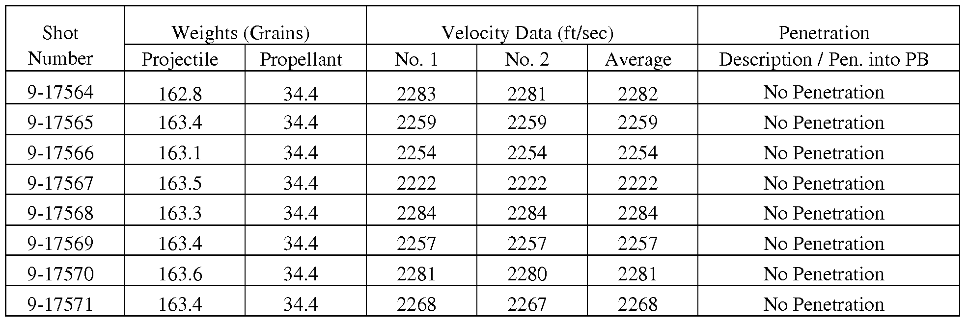
Table IB: Ballistic Test Results - 2750fps impacts by 0.30 CAL AP-M2

-(PB) Denotes phone book and value indicates the No. of pages penetrated. 1 PB = ~ 1200 pages.
- Single center tile impacts at two velocities: 2250 + 30 fps and 2750 + 30 fps.
-(1) Denotes the recovered projectile was fractured, not intact.
-(2) Denotes the projectile was thrown to the far left exiting the target and missed the phone books.
Table 2: Layer Sequence vs. Result of Ballistic Impact Test

ROBAX SCHOTTROBAX - ceramized
ROBAXG SCHOTTROBAX - glassy
PC GE LEXAN Polycarbonate backing
BOROFLOAT SCHOTT BOROFLOAT
Samples are considered to pass if and only if the spall layer is not pierced by fragments (i.e., penetration). In the tables, CP denotes "Complete Penetration". If at least one fragment pierced the spall layer then the layer failed. PP denotes "Partial Penetration". If the projectile penetrated into the laminate and was stopped, and no fragments pierced the spall layer, the sample passed. The ROBAX 8mm/BOROFLOAT 21mm/ROBAX8mm samples passed at both impact velocities (9-17566, 9-17574). The ROBAX 8mm/ROBAX 8mm/ROBAX 8mm/BOROFLOAT 21mm samples (9-17570, 9-17578) induced different defeat modes. One preferred design is a combination of ROBAX 8mm/ROBAX 8mm/BOROFLOAT 21mm (9- 17579), which almost passed and induced core fragmentation by tipping the projectile and ROBAX 8mm/BOROFLOAT 21mm/ROBAX8mm(9-17566, 9-17574). The combination of both designs is desired in order to achieve comparable ballistic performance of the full-scale window, and to achieve multi-hit capability (three shots placed in a 120mm triangle).
Example 3: Multi-hit Example
Three 500mm x 500mm test coupons for multi-hit testing are prepared, and tested against an 0.30 cal. AP-M2 round at nominal 2750fps; the shot pattern is a 120mm triangle, the shot sequence is 12 O'clock, 4 O'clock and 8 O'clock. The nominal areal density of the samples is 29 psf; due to slight variations in the thickness of the individual glass and glass-ceramic layers, the areal density of the samples as manufactured is 29.7psf (samples 1 and 2) and 30psf (sample 3).
The samples have the following structure:
Samplel
500mm x 500mm, edges sealed, frameless
Strikeface 6mm Borofloat
Interlayer Huntsman PE-501 - 25mil
PIy Ol 8mm Robax Glass-ceramic
Interlayer Huntsman PE-501 - 25mil
Ply 02 8mm Robax Glass-Ceramic
Interlayer Huntsman PE-501 - 25mil
Ply 03 21mm Borofloat
Interlayer Huntsman PE-501 - 25mil
Ply 04 8mm Robax
Interlayer Huntsman PE-501 - 75mil
Spall-Layer 9mm PMMA laminated to 9mm PC (Lexan)
Sample 2
500mm x 500mm, edges sealed, frameless
Strikeface 6mm Borofloat
Interlayer Huntsman PE-501 - 25mil
PIy Ol 8mm Robax Glassceramic
Interlayer PVB - 25mil
Ply 02 8mm Robax Glass-Ceramic
Interlayer Huntsman PE-501 - 25mil
Ply 03 21mm Borofloat
Interlayer Huntsman PE-501 - 25mil
Ply 04 8mm Robax
Interlayer Huntsman PE-501 - 75mil
Spall-Layer 9mm PMMA laminated to 9mm PC (Lexan)
Sample 3
500mm x 500mm, edges sealed, frameless
Strikeface 6mm Borofloat
Interlayer Huntsman PE-501 - 25mil
PIy Ol 8mm Robax Glassceramic
Interlayer PVB - 25mil
Ply 02 8mm Robax Glass-Ceramic
Interlayer Huntsman PE-501 - 25mil
Ply 03a 11mm Borofloat
Interlayer Huntsman PE-501 - 25mil
Ply 03b 11mm Borofloat
Interlayer Huntsman PE-501 - 25mil
Ply 04 8mm Robax
Interlayer Huntsman PE-501 - 75mil
Spall-Layer 9mm PMMA laminated to 9mm PC (Lexan)
Test Results (Multi-Hit Test)


Whereas sample No 1 failed on the 2n and the 3r shot, samples No. 2 and No. 3 according to the present invention withstood all three shots. Figure 11 shows the strike face of sample No. 3 after the test, Figure 12 shows the back (spall layer) of sample No 3. For samples No. 2 and No. 3, no bulging or other deformation of the spall layer is observed.
The entire disclosures of all applications, patents and publications, cited herein are incorporated by reference herein.
Additionally, the following five references provide background and general knowledge to one skilled in the art and are incorporated herein by reference.
1. NATO AEP-55 Volume 1 (Edition 1) Feb. 2005 (PROCEDURES FOR EVALUATING THE PROTECTION LEVELS OF LOGISTIC AND LIGHT ARMOURED VEHICLES FOR KE AND ARTILLERY THREATS).
2. US Military Specification MIL-G-5485D (22-Feb-1993).
3. Horsfall et al. A Comparison of the Performance of Various Light Armour Piercing Ammunition, Journal of Battlefield Technology, VoI 3, No 3, November 2000.
4. Moy, P. et al. Dynamic stress-strain response and failure behaviour of PMMA. Proceedings of the ASME International Mechanical Engineering Conference, Washington, DC, November 2003.
5. Kinloch A.I. Fracture Behavior of Polymers, Applied Science Publishers, New York, NY.
The preceding examples can be repeated with similar success by substituting the generically or specifically described reactants and/or operating conditions of this invention for those used in the preceding examples.
Without further elaboration, it is believed that one skilled in the art can, using the preceding description, utilize the present invention to its fullest extent. The preceding preferred specific embodiments are, therefore, to be construed as merely illustrative, and not limitative of the remainder of the disclosure in any way whatsoever.
From the foregoing description, one skilled in the art can easily ascertain the essential characteristics of this invention and, without departing from the spirit and scope thereof, can make various changes and modifications of the invention to adapt it to various usages and conditions.
Claims
1. A transparent multi-layer laminate comprising: a glass-ceramic layer, a soda-lime or borosilicate glass layer, a glass-ceramic layer, a polymer spall layer and wherein said soda-lime or borosilicate glass layer is disposed between said glass-ceramic layers and the layers are bound together by polymer interlayers and the overall thickness of the composite is less than 80 mm.
2. A laminate according to claim 1, wherein said glass ceramic layers are each independently a lithium-alumo-silicate glass ceramic or a lithium-disilicate glass ceramic.
3. A laminate according to claim 1, wherein said spall layer is polycarbonate, polymethylmethacrylate, or a laminate of polycarbonate and polymethyl methacrylate.
4. A laminate according to claim 1, wherein said interlayer is a polyurethane or polyvinylbutyral film.
5. A laminate according to claim 1, wherein the soda-lime or borosilicate glass layer is 14 to 25 mm thick.
6. A laminate according to claim 1, wherein each glass-ceramic layer is 6-14 mm thick.
7. A glass based transparent armour comprising a laminate of claim 1.
8. A laminate according to claim 5, wherein the soda-lime or borosilicate glass layer is two individual layers bound together by a polymer interlayer.
9.A transparent multi-layer laminate comprising:
a) an outer strike face layer, b) at least three glass-ceramic layers,
c) a soda-lime or borosilicate glass layer,
d) a polymer spall layer having a backside,
wherein layers b) and c) are disposed between said strike face layer a) and said polymer spall layer d), the layers are bound together by polymer interlayers and the overall thickness of the composite is less than 80 mm.
10. A laminate according to claim 9, wherein said strike face is 3-6 mm thick borosilicate glass.
1 LA laminate according to claim 9, wherein said glass ceramic layers are each independently a lithium-alumo-silicate glass ceramic or a lithium-disilicate glass ceramic.
12. A laminate according to claim 9, wherein said spall layer is polycarbonate, polymethylmethacrylate, or a laminate of polycarbonate and polymethyl methacrylate.
13. A laminate according to claim 9, wherein said interlayer is a polyurethane or polyvinylbutyral film.
14. A laminate according to claim 9, wherein the strike face is 3-6 mm thick, each layer b) is 6-14 mm thick, layer c) is 14 to 25 mm thick, the spall layer d) is 10-20 mm thick, and each of said interlayers is 10-80 mil thick.
15. A laminate according to claim 9, wherein the overall thickness of the composite is less than 70 mm.
16. A glass based transparent armour comprising a laminate of claim 9.
17. An armour of claim 16, which can defeat an 0.30 cal. AP-M2 projectile at an impact speed of up to 2750 fps.
18. A method of securing a space from a projectile comprising placing an armour according to claim 17 between said space and said projectile.
19. A transparent multi-layer laminate comprising:
at least three glass-ceramic layers,
a soda-lime or borosilicate glass layer disposed between two of said glass ceramic layers,
a polymer spall layer having a backside,
the layers are bound together by polymer interlayers and the overall thickness of the composite is less than 80 mm.
20. A glass based transparent armour comprising a laminate of claim 19.
21. A laminate according to claim 19, wherein the soda-lime or borosilicate glass layer is 14 to 25 mm thick.
22. A laminate according to claim 19, wherein each glass-ceramic layer is 6-14 mm thick.
23. A laminate according to claim 19, wherein the overall thickness of the composite is less than 70 mm thick.
24. A method of securing a space from a projectile comprising placing an armour according to claim 20 between said space and said projectile.
25. A laminate according to claim 19, wherein said glass ceramic layers are each independently a lithium-alumo-silicate glass ceramic or a lithium-disilicate glass ceramic.
Priority Applications (3)
| Application Number | Priority Date | Filing Date | Title |
|---|---|---|---|
| EP08834214.2A EP2244988B1 (en) | 2007-09-27 | 2008-09-26 | Lightweight transparent armor window |
| CN2008801095001A CN101815688B (en) | 2007-09-27 | 2008-09-26 | Lightweight transparent armor window |
| IL204586A IL204586A (en) | 2007-09-27 | 2010-03-18 | Transparent multi-layer laminates, transparent armors comprising them and method of securing a space from projectiles |
Applications Claiming Priority (4)
| Application Number | Priority Date | Filing Date | Title |
|---|---|---|---|
| US97566107P | 2007-09-27 | 2007-09-27 | |
| US60/975,661 | 2007-09-27 | ||
| US12/052,021 | 2008-03-20 | ||
| US12/052,021 US8603616B1 (en) | 2007-09-27 | 2008-03-20 | Lightweight transparent armor window |
Publications (2)
| Publication Number | Publication Date |
|---|---|
| WO2009042877A2 true WO2009042877A2 (en) | 2009-04-02 |
| WO2009042877A3 WO2009042877A3 (en) | 2009-05-28 |
Family
ID=40512120
Family Applications (1)
| Application Number | Title | Priority Date | Filing Date |
|---|---|---|---|
| PCT/US2008/077873 WO2009042877A2 (en) | 2007-09-27 | 2008-09-26 | Lightweight transparent armor window |
Country Status (6)
| Country | Link |
|---|---|
| US (1) | US8603616B1 (en) |
| EP (1) | EP2244988B1 (en) |
| CN (1) | CN101815688B (en) |
| IL (1) | IL204586A (en) |
| TW (1) | TWI450869B (en) |
| WO (1) | WO2009042877A2 (en) |
Cited By (16)
| Publication number | Priority date | Publication date | Assignee | Title |
|---|---|---|---|---|
| US20100154622A1 (en) * | 2008-11-13 | 2010-06-24 | Thilo Zachau | Highly transparent impact-resistant glass ceramic |
| WO2011150047A1 (en) * | 2010-05-28 | 2011-12-01 | Corning Incorporated | Transparent laminates comprising intermediate or anomalous glass |
| EP2409834A1 (en) | 2010-07-23 | 2012-01-25 | Schott AG | Laminated transparent glazing, method for producing and bending the same and use of same |
| US8176831B2 (en) | 2009-04-10 | 2012-05-15 | Nova Research, Inc. | Armor plate |
| US20120198989A1 (en) * | 2006-08-30 | 2012-08-09 | Varshneya Arun K | Transparent armor systems, methods for making and methods for using |
| WO2012044385A3 (en) * | 2010-06-30 | 2012-08-09 | Corning Incorporated | Transparent armor with improved multi-hit performance by use of a thin cover glass |
| WO2012145664A1 (en) * | 2011-04-22 | 2012-10-26 | Schott Corporation | Light weight temperature resistant transparent laminate structure |
| WO2013064491A1 (en) * | 2011-10-31 | 2013-05-10 | Jan Hampel | Bullet-resistant transparent composite pane |
| US8695476B2 (en) | 2011-03-14 | 2014-04-15 | The United States Of America, As Represented By The Secretary Of The Navy | Armor plate with shock wave absorbing properties |
| DE102012220009A1 (en) | 2012-11-02 | 2014-05-08 | Schott Ag | Monolithic breakdown-resistant laminated glass useful as viewing panel in architectural glazing, comprises drive side cover panel, drive opposite cover panel, additional panel, panel made of impact-resistant plastic, and composite layer |
| US20150024165A1 (en) * | 2013-07-22 | 2015-01-22 | U.S. Army Research Laboratory Attn: Rdrl-Loc-I | Transparent armor construction |
| US20150258750A1 (en) * | 2012-08-31 | 2015-09-17 | Corning Incorporated | Strengthened thin glass-polymer laminates |
| US20150354923A1 (en) * | 2011-04-08 | 2015-12-10 | Schott Corporation | Multilayer armor |
| EP3309500A1 (en) * | 2016-10-11 | 2018-04-18 | Saint-Gobain Glass France | Framed, transparent and bullet resistant glasing with enforced boundary |
| EP3309501A1 (en) * | 2016-10-11 | 2018-04-18 | Saint-Gobain Glass France | Framed, transparent and bullet resistant glasing with enforced boundary |
| WO2019186115A1 (en) | 2018-03-27 | 2019-10-03 | Pilkington Group Limited | Laminated glazing |
Families Citing this family (21)
| Publication number | Priority date | Publication date | Assignee | Title |
|---|---|---|---|---|
| US20150132560A9 (en) * | 2008-11-13 | 2015-05-14 | Thilo Zachau | Highly transparent impact-resistant plate laminate and armored or bulletproof glass and articles made with same |
| US20140290473A1 (en) * | 2011-06-21 | 2014-10-02 | Bayer Materialscience Llc | Polycarbonate laminate for close-proximity blast events |
| US10041767B2 (en) | 2013-11-14 | 2018-08-07 | The Regents Of The University Of Michigan | Blast/impact frequency tuning and mitigation |
| JP6426180B2 (en) * | 2013-11-14 | 2018-11-21 | ザ・リージェンツ・オブ・ザ・ユニバーシティ・オブ・ミシガンThe Regents Of The University Of Michigan | Blast / impact frequency tuning and mitigation |
| CN104057666B (en) * | 2014-06-30 | 2015-09-30 | 江苏中电振华晶体技术有限公司 | A kind of monocrystalline sapphire bulletproof glass and processing method thereof being easy to processing |
| US9285191B2 (en) | 2014-07-01 | 2016-03-15 | The United States Of America, As Represented By The Secretary Of The Navy | Polymer coatings for enhanced and field-repairable transparent armor |
| ITUB20154221A1 (en) * | 2015-10-08 | 2017-04-08 | Gregorio Vincenzo Di | TRANSPARENT SUPPORT SLAB FOR CONSTRUCTION AND FURNISHING |
| US10293582B2 (en) | 2016-03-11 | 2019-05-21 | Solutia Inc. | Cellulose ester multilayer interlayers |
| US10293580B2 (en) | 2016-03-11 | 2019-05-21 | Solutia Inc. | Cellulose ester multilayer interlayers |
| US10293585B2 (en) | 2016-03-11 | 2019-05-21 | Solutia Inc. | Cellulose ester multilayer interlayers |
| US10195826B2 (en) | 2016-03-11 | 2019-02-05 | Solutia Inc. | Cellulose ester multilayer interlayers |
| US10293584B2 (en) | 2016-03-11 | 2019-05-21 | Solutia Inc. | Cellulose ester multilayer interlayers |
| US10300682B2 (en) | 2016-03-11 | 2019-05-28 | Solutia Inc. | Cellulose ester multilayer interplayers |
| US10293583B2 (en) | 2016-03-11 | 2019-05-21 | Solutia Inc. | Cellulose ester multilayer interlayers |
| US10293579B2 (en) | 2016-03-11 | 2019-05-21 | Solutia Inc. | Cellulose ester multilayer interlayers |
| CN106273907B (en) * | 2016-08-05 | 2019-01-04 | 安徽金星包装有限公司 | A kind of compound glass bottle cap and preparation method thereof |
| CO2017012225A1 (en) | 2017-08-23 | 2018-02-20 | Agp America Sa | Transparent multi impact shield |
| CO2018000469A1 (en) * | 2017-11-30 | 2018-04-30 | Agp America Sa | Automotive laminate with invisible solid edge substrate compensation layer |
| KR102252182B1 (en) * | 2018-01-10 | 2021-05-14 | 주식회사 엘지화학 | Manufacturing method for curved laminated glass and curved laminated glass manufactured by the same |
| CN111038045A (en) * | 2019-12-12 | 2020-04-21 | 中国建筑材料科学研究总院有限公司 | Transparent armor plate and manufacturing method thereof |
| CN111521066A (en) * | 2020-05-13 | 2020-08-11 | 中国电子科技集团公司第三十三研究所 | Light double-waveband transparent armor and preparation method thereof |
Family Cites Families (72)
| Publication number | Priority date | Publication date | Assignee | Title |
|---|---|---|---|---|
| US2391353A (en) | 1941-12-04 | 1945-12-18 | Hiram W Sheridan | Armor |
| US3291623A (en) | 1965-04-29 | 1966-12-13 | Electro Refractories & Abrasiv | Refractory body and method of making same |
| US3765300A (en) | 1967-05-22 | 1973-10-16 | Carborundum Co | Dense carbide composite for armor and abrasives |
| USH1567H (en) | 1967-09-07 | 1996-08-06 | The United States Of America As Represented By The Secretary Of The Army | Transparent ceramic armor |
| US3573150A (en) | 1968-07-24 | 1971-03-30 | Us Army | Transparent armor |
| US3796564A (en) | 1969-06-19 | 1974-03-12 | Carborundum Co | Dense carbide composite bodies and method of making same |
| US3857744A (en) | 1970-01-19 | 1974-12-31 | Coors Porcelain Co | Method for manufacturing composite articles containing boron carbide |
| US3671374A (en) | 1970-05-20 | 1972-06-20 | Goodyear Aerospace Corp | Composite armor |
| US3725015A (en) | 1970-06-08 | 1973-04-03 | Norton Co | Process for forming high density refractory shapes and the products resulting therefrom |
| GB1325204A (en) | 1970-10-07 | 1973-08-01 | United States Borax Chem | Production of hard articles of a boron-carbon compound |
| US3808012A (en) | 1971-04-19 | 1974-04-30 | Carborundum Co | Dense composite ceramic bodies |
| US3730827A (en) | 1971-11-22 | 1973-05-01 | Norton Research Corp Ltd | Boron carbide ballistic armor modified with copper |
| US3947550A (en) | 1973-08-20 | 1976-03-30 | Ford Motor Company | Method of making a silicon carbide article of less than full density |
| US4028476A (en) | 1974-07-18 | 1977-06-07 | Phillips Petroleum Company | Transparent polyamide armor |
| US4154787A (en) | 1977-07-25 | 1979-05-15 | Coors Porcelain Company | Method for manufacturing silicon carbide bodies |
| US4209474A (en) | 1977-08-31 | 1980-06-24 | General Electric Company | Process for preparing semiconducting silicon carbide sintered body |
| US4704943A (en) | 1981-06-15 | 1987-11-10 | Mcdougal John A | Impact structures |
| US4473653A (en) | 1982-08-16 | 1984-09-25 | Rudoi Boris L | Ballistic-resistant glass-ceramic and method of preparation |
| US4494342A (en) | 1982-12-21 | 1985-01-22 | Decker G Warren | Insulated glass adaptive method and apparatus |
| US4737327A (en) | 1983-02-07 | 1988-04-12 | Kurosaki Refractories Co., Ltd. | Process for producing silicon carbide sintered product |
| GB8323994D0 (en) | 1983-09-07 | 1983-10-12 | Atomic Energy Authority Uk | Reaction-bonded silicon carbide artefacts |
| US4633756A (en) | 1984-05-21 | 1987-01-06 | Rudoi Boris L | Bullet proof armor shield |
| US4869175A (en) | 1985-01-25 | 1989-09-26 | Mcdougal John A | Impact structures |
| US4953442A (en) | 1986-01-07 | 1990-09-04 | Harsco Corporation | Magnetized ceramic armor system |
| GB2190077B (en) * | 1987-11-10 | 1990-12-19 | Ceramic Developments | Armour materials. |
| IT1223485B (en) | 1987-12-16 | 1990-09-19 | Eniricerche Spa | PROCEDURE FOR THE PREPARATION OF CERAMIC COMPONENTS |
| JPH02129071A (en) | 1988-11-07 | 1990-05-17 | Tone Boring Co | Production of silicon carbide ceramics |
| US4911061A (en) | 1989-03-22 | 1990-03-27 | General Dynamics Land Systems, Inc. | Composite ceramic armor and method for making same |
| DE4025239C1 (en) | 1990-08-09 | 1991-12-19 | Hoechst Ceramtec Ag, 8672 Selb, De | |
| US5502011A (en) | 1991-10-21 | 1996-03-26 | Sumitomo Electric Industries, Ltd. | Silicon nitride sintered body |
| US5567529A (en) | 1991-11-27 | 1996-10-22 | E. I. Du Pont De Nemours And Company | Multilayered glass laminate having enhanced resistance to penetration by high velocity projectiles |
| US5640666A (en) | 1993-06-01 | 1997-06-17 | University Of Florida | Composite silicide/silicon carbide mechanical alloy |
| GB9319450D0 (en) | 1993-09-21 | 1995-03-08 | Gec Alsthom Ltd | Transparent glass ceramic |
| US5496640A (en) * | 1994-08-15 | 1996-03-05 | Artistic Glass Products Company | Fire resistant transparent laminates |
| US5783297A (en) | 1995-08-16 | 1998-07-21 | Cemcom Corporation | Materials for shock attenuation |
| JPH10279376A (en) | 1997-03-31 | 1998-10-20 | Toyo Tanso Kk | Member for continuous casting using carbon-silicon carbide composite material |
| KR100497723B1 (en) | 1997-04-03 | 2005-06-23 | 코닝 인코포레이티드 | Transparent apatite glass-ceramics |
| FR2764841B1 (en) | 1997-06-18 | 1999-07-16 | Saint Gobain Vitrage | ARMORED WINDOWS, ESPECIALLY FIXED OR MOBILE SIDE FOR MOTOR VEHICLE |
| US6197429B1 (en) | 1998-02-26 | 2001-03-06 | Corning Incorporated | Method for making transparent glass-ceramics with high temperature dimensional stability |
| EP1208150A4 (en) | 1999-06-11 | 2005-01-26 | Sydney Hyman | Image making medium |
| FR2795365B1 (en) | 1999-06-25 | 2002-07-12 | Saint Gobain Vitrage | ARMORED SHEET GLASS, PARTICULARLY FOR MOTOR VEHICLES |
| US7104177B1 (en) | 2000-01-11 | 2006-09-12 | Aghajanian Michael K | Ceramic-rich composite armor, and methods for making same |
| US6609452B1 (en) | 2000-01-11 | 2003-08-26 | M Cubed Technologies, Inc. | Silicon carbide armor bodies, and methods for making same |
| US6408733B1 (en) | 2000-02-14 | 2002-06-25 | William J. Perciballi | Ceramic armor apparatus for multiple bullet protection |
| US6555173B1 (en) | 2000-11-08 | 2003-04-29 | Honeywell International Inc. | Carbon barrier controlled metal infiltration layer for enhanced oxidation protection |
| CA2428958A1 (en) | 2000-11-21 | 2002-09-06 | M Cubed Technologies, Inc. | Boron carbide composite bodies, and methods for making same |
| US6995103B2 (en) | 2000-11-21 | 2006-02-07 | M Cubed Technologies, Inc. | Toughness enhanced silicon-containing composite bodies, and methods for making same |
| US6862970B2 (en) | 2000-11-21 | 2005-03-08 | M Cubed Technologies, Inc. | Boron carbide composite bodies, and methods for making same |
| US7284469B2 (en) | 2001-01-08 | 2007-10-23 | Glasscerax Ltd. | Protection from kinetic threats using glass-ceramic material |
| DE10110225C2 (en) | 2001-03-02 | 2003-07-17 | Schott Glas | Glass-ceramic support material, process for its preparation and its use |
| BR0211579A (en) | 2001-08-02 | 2004-07-13 | 3M Innovative Properties Co | Glass-ceramic, beads, plurality of abrasive particles, abrasive article, and methods for abrading a surface, for making glass-ceramic, for making a glass-ceramic article, and for making abrasive particles |
| GB2379659A (en) * | 2001-09-13 | 2003-03-19 | Alstom | Making a transparent glass-ceramic armour |
| US6699412B2 (en) | 2001-11-20 | 2004-03-02 | Corning Incorporated | Compression-molded silicon carbide structures |
| IL149479A0 (en) | 2002-05-06 | 2004-02-19 | Plasan Sasa | Composite armor structure |
| US20040157720A1 (en) | 2002-08-20 | 2004-08-12 | Nippon Electric Glass Co., Ltd. | Crystallized glass |
| US6895851B1 (en) | 2003-06-16 | 2005-05-24 | Ceramics Process Systems | Multi-structure metal matrix composite armor and method of making the same |
| FR2863607B1 (en) | 2003-12-11 | 2006-09-29 | Snc Eurokera | VITROCERAMICS WITH MODIFIED SURFACE AND THEIR PREPARATION |
| US6952530B2 (en) | 2003-12-19 | 2005-10-04 | The Aerospace Corporation | Integrated glass ceramic systems |
| CO5680113A1 (en) * | 2004-09-28 | 2006-09-29 | Glass Tehcnology Invest | SHIELDED GLASS COMPOSITION WITH PERIMETER REINFORCEMENT |
| KR20070107678A (en) | 2004-12-03 | 2007-11-07 | 씨씨씨아이피 엘엘씨 | Optically transmissive armor composite |
| US7335331B1 (en) | 2005-03-01 | 2008-02-26 | Husnay Dana M | Method for making ceramic plates |
| MX2007015574A (en) | 2005-06-10 | 2008-02-25 | Saint Gobain Ceramics | Transparent ceramic composite. |
| US8304078B2 (en) | 2005-09-12 | 2012-11-06 | Saxon Glass Technologies, Inc. | Chemically strengthened lithium aluminosilicate glass having high strength effective to resist fracture upon flexing |
| CA2654845A1 (en) | 2006-06-13 | 2007-12-21 | D&D Salomon Investment Ltd. | Glass-ceramic materials having a predominant spinel-group crystal phase |
| IL179592A (en) | 2006-11-26 | 2012-03-29 | Moshe Ravid | Armor panel |
| US8161862B1 (en) * | 2007-01-08 | 2012-04-24 | Corning Incorporated | Hybrid laminated transparent armor |
| DE202007001565U1 (en) * | 2007-02-02 | 2007-04-05 | Isoclima Gmbh | Armoured glass comprises at least one optically transparent sintered glass material made of aluminium oxynitride |
| US8176828B2 (en) | 2007-03-21 | 2012-05-15 | Schott Corporation | Glass-ceramic with laminates |
| US9091510B2 (en) | 2007-03-21 | 2015-07-28 | Schott Corporation | Transparent armor system and method of manufacture |
| US20080280034A1 (en) | 2007-05-11 | 2008-11-13 | 3M Innovative Properties Company | Pavement marking and reflective elements having microspheres comprising lanthanum oxide and aluminum oxide with zirconia, titania, or mixtures thereof |
| US20100275767A1 (en) * | 2007-08-31 | 2010-11-04 | Linda Ruth Pinckney | Multi-hit capable transparent, multi-stack armor system |
| DE102008043718B9 (en) * | 2008-11-13 | 2012-05-31 | Schott Ag | Highly transparent impact-resistant disc laminate comprising at least one slice of a lithium alumino-silicate glass-ceramic and its use |
-
2008
- 2008-03-20 US US12/052,021 patent/US8603616B1/en active Active
- 2008-09-26 TW TW97137341A patent/TWI450869B/en not_active IP Right Cessation
- 2008-09-26 EP EP08834214.2A patent/EP2244988B1/en active Active
- 2008-09-26 WO PCT/US2008/077873 patent/WO2009042877A2/en active Application Filing
- 2008-09-26 CN CN2008801095001A patent/CN101815688B/en not_active Expired - Fee Related
-
2010
- 2010-03-18 IL IL204586A patent/IL204586A/en not_active IP Right Cessation
Non-Patent Citations (1)
| Title |
|---|
| None |
Cited By (28)
| Publication number | Priority date | Publication date | Assignee | Title |
|---|---|---|---|---|
| US9162426B2 (en) * | 2006-08-30 | 2015-10-20 | Saxon Glass Technologies, Inc. | Transparent armor systems, methods for making and methods for using |
| US20120198989A1 (en) * | 2006-08-30 | 2012-08-09 | Varshneya Arun K | Transparent armor systems, methods for making and methods for using |
| US8404350B2 (en) * | 2008-11-13 | 2013-03-26 | Schott Ag | Highly transparent impact-resistant glass ceramic |
| US20100154622A1 (en) * | 2008-11-13 | 2010-06-24 | Thilo Zachau | Highly transparent impact-resistant glass ceramic |
| US8176831B2 (en) | 2009-04-10 | 2012-05-15 | Nova Research, Inc. | Armor plate |
| WO2011150047A1 (en) * | 2010-05-28 | 2011-12-01 | Corning Incorporated | Transparent laminates comprising intermediate or anomalous glass |
| WO2012044385A3 (en) * | 2010-06-30 | 2012-08-09 | Corning Incorporated | Transparent armor with improved multi-hit performance by use of a thin cover glass |
| US8640591B2 (en) | 2010-06-30 | 2014-02-04 | Corning Incorporated | Transparent armor with improved multi-hit performance by use of a thin cover glass |
| DE102010032092A1 (en) | 2010-07-23 | 2012-01-26 | Schott Ag | Laminated, transparent disc set, method for its production and bending and its use |
| EP2409834A1 (en) | 2010-07-23 | 2012-01-25 | Schott AG | Laminated transparent glazing, method for producing and bending the same and use of same |
| US8695476B2 (en) | 2011-03-14 | 2014-04-15 | The United States Of America, As Represented By The Secretary Of The Navy | Armor plate with shock wave absorbing properties |
| US20150354923A1 (en) * | 2011-04-08 | 2015-12-10 | Schott Corporation | Multilayer armor |
| US10030941B2 (en) * | 2011-04-08 | 2018-07-24 | Oran Safety Glass Inc. | Multilayer armor |
| EP2699405A4 (en) * | 2011-04-22 | 2015-05-13 | Schott Corp | Light weight temperature resistant transparent laminate structure |
| WO2012145664A1 (en) * | 2011-04-22 | 2012-10-26 | Schott Corporation | Light weight temperature resistant transparent laminate structure |
| US10046540B2 (en) | 2011-04-22 | 2018-08-14 | Oran Safety Glass Inc. | Light weight temperature resistant transparent laminate structure |
| WO2013064491A1 (en) * | 2011-10-31 | 2013-05-10 | Jan Hampel | Bullet-resistant transparent composite pane |
| DE102011117340B4 (en) * | 2011-10-31 | 2017-05-11 | Iabg Industrieanlagen-Betriebsgesellschaft Mbh | Bullet resistant transparent composite disc |
| US20150258750A1 (en) * | 2012-08-31 | 2015-09-17 | Corning Incorporated | Strengthened thin glass-polymer laminates |
| US10953633B2 (en) * | 2012-08-31 | 2021-03-23 | Corning Incorporated | Strengthened thin glass-polymer laminates |
| DE102012220009A1 (en) | 2012-11-02 | 2014-05-08 | Schott Ag | Monolithic breakdown-resistant laminated glass useful as viewing panel in architectural glazing, comprises drive side cover panel, drive opposite cover panel, additional panel, panel made of impact-resistant plastic, and composite layer |
| DE102012220009B4 (en) | 2012-11-02 | 2018-08-16 | Schott Ag | Bullet-resistant and break-through resistant laminated glass and its use |
| US20150024165A1 (en) * | 2013-07-22 | 2015-01-22 | U.S. Army Research Laboratory Attn: Rdrl-Loc-I | Transparent armor construction |
| US9383173B2 (en) * | 2013-07-22 | 2016-07-05 | The United States Of America As Represented By The Secretary Of The Army | Transparent armor construction |
| EP3309500A1 (en) * | 2016-10-11 | 2018-04-18 | Saint-Gobain Glass France | Framed, transparent and bullet resistant glasing with enforced boundary |
| EP3309501A1 (en) * | 2016-10-11 | 2018-04-18 | Saint-Gobain Glass France | Framed, transparent and bullet resistant glasing with enforced boundary |
| WO2019186115A1 (en) | 2018-03-27 | 2019-10-03 | Pilkington Group Limited | Laminated glazing |
| US11511525B2 (en) | 2018-03-27 | 2022-11-29 | Pilkington Group Limited | Laminated glazing |
Also Published As
| Publication number | Publication date |
|---|---|
| TWI450869B (en) | 2014-09-01 |
| EP2244988B1 (en) | 2019-12-25 |
| IL204586A0 (en) | 2010-11-30 |
| WO2009042877A3 (en) | 2009-05-28 |
| IL204586A (en) | 2015-06-30 |
| EP2244988A4 (en) | 2014-04-02 |
| US8603616B1 (en) | 2013-12-10 |
| CN101815688A (en) | 2010-08-25 |
| EP2244988A2 (en) | 2010-11-03 |
| TW200930674A (en) | 2009-07-16 |
| CN101815688B (en) | 2013-07-17 |
| US20130305912A1 (en) | 2013-11-21 |
Similar Documents
| Publication | Publication Date | Title |
|---|---|---|
| US8603616B1 (en) | Lightweight transparent armor window | |
| AU2006257867B2 (en) | Transparent ceramic composite | |
| JP6070969B2 (en) | Multilayer transparent lightweight safety glazing | |
| EP2699405B1 (en) | Light weight temperature resistant transparent laminate structure | |
| WO2008147391A2 (en) | Transparent ballistic resistant armor | |
| JP3073524B2 (en) | Multilayer glass laminates with enhanced resistance to penetration by high velocity projectiles | |
| US20100126336A1 (en) | Optically transmissive armor composite and method of manufacture | |
| AU2012244085B2 (en) | Transparent ceramic composite | |
| WO2004055468A1 (en) | Bulletproof transparent plate |
Legal Events
| Date | Code | Title | Description |
|---|---|---|---|
| WWE | Wipo information: entry into national phase |
Ref document number: 200880109500.1 Country of ref document: CN |
|
| 121 | Ep: the epo has been informed by wipo that ep was designated in this application |
Ref document number: 08834214 Country of ref document: EP Kind code of ref document: A2 |
|
| WWE | Wipo information: entry into national phase |
Ref document number: 204586 Country of ref document: IL |
|
| NENP | Non-entry into the national phase |
Ref country code: DE |
|
| WWE | Wipo information: entry into national phase |
Ref document number: 2008834214 Country of ref document: EP |