明 細 書 Specification
スピーカシステム 技術分野 Speaker system technology
[0001] 本発明は、少なくとも 2個のスピーカを含むスピーカユニットを 2対含むスピーカシス テムに関する。 [0001] The present invention relates to a speaker system including two pairs of speaker units including at least two speakers.
背景技術 Background art
[0002] 従来のスピーカシステムとしては、例えば、 Lチャンネルスピーカユニットと、 Rチャン ネルスピーカユニットと、センタースピーカユニットとを備えるものがある(例えば、特許 文献 1参照)。上記 3つのスピーカユニットは、車両の運転席及び助手席の前方中央 にそれぞれ配置される。 Lチャンネルスピーカユニットは、水平方向においてその指 向軸が車両の直進方向を基準として反時計回りの方向に回動した向きとされ、且つ 垂直方向において指向軸が車両の直進方向に対して所定の角度傾斜した向きとさ れる。 Rチャンネルスピーカユニットは、水平方向においてその指向軸が車両の直進 方向から時計回りの方向に回動した向きとされ、且つ垂直方向において指向軸が車 両の進行方向に所定の角度傾斜した向きとされる。センタースピーカユニットは、 Lチ ヤンネル信号の逆相信号である L信号と Rチャンネル信号の逆相信号である R 信号とを加算した L— R信号を出力する。 [0002] A conventional speaker system includes, for example, an L channel speaker unit, an R channel speaker unit, and a center speaker unit (see, for example, Patent Document 1). The three speaker units are arranged in the front center of the driver's seat and front passenger seat, respectively. The L-channel speaker unit has a direction in which the pointing axis in the horizontal direction rotates counterclockwise with respect to the straight traveling direction of the vehicle, and the pointing shaft in the vertical direction has a predetermined direction with respect to the straight traveling direction of the vehicle. The direction is inclined at an angle. The R channel speaker unit has a direction in which the directional axis rotates in a clockwise direction from the straight traveling direction of the vehicle in the horizontal direction, and a direction in which the directional axis inclines by a predetermined angle in the traveling direction of the vehicle in the vertical direction. Is done. The center speaker unit outputs an LR signal obtained by adding the L signal, which is the reverse phase signal of the L channel signal, and the R signal, which is the reverse phase signal of the R channel signal.
特許文献 1 :特開 2004— 289341号公報 Patent Document 1: Japanese Patent Application Laid-Open No. 2004-289341
発明の開示 Disclosure of the invention
発明が解決しょうとする課題 Problems to be solved by the invention
[0003] このような従来の車載用のスピーカシステムにあっては、運転席の聴者に届くまで の Lチャンネル信号の経路長と Rチャンネル信号の経路長との間に差 (経路長差)が 生じるため、両チャンネル信号の間には聴者に届くまでに位相差及び遅延が生じる 。これについては、助手席側の聴者側でも同様である。上記の位相差及び遅延によ り、各聴者はオーディオを聴レ、て!/、て違和感を覚えるとレ、う問題点がある。 [0003] In such a conventional in-vehicle speaker system, there is a difference (path length difference) between the path length of the L channel signal and the path length of the R channel signal until reaching the listener at the driver's seat. As a result, there is a phase difference and delay between the two channel signals before reaching the listener. The same applies to the passenger side of the passenger seat. Due to the above phase difference and delay, each listener has a problem when listening to audio and feeling uncomfortable.
[0004] 本発明は、力、かる点に鑑みてなされたものであり、複数の聴者に違和感を与えない リスニング環境を同時に提供可能なスピーカシステムを提供することを目的とする。
課題を解決するための手段 [0004] The present invention has been made in view of power and strength, and an object of the present invention is to provide a speaker system that can simultaneously provide a listening environment that does not cause discomfort to a plurality of listeners. Means for solving the problem
[0005] 上記目的を達成するために、本発明のスピーカシステムは、第 1の聴取位置で聴取 される音を出力する第 1のスピーカと、第 2の聴取位置で聴取される音を出力する第 2のスピーカとを含む第 1のスピーカユニットと、第 1の聴取位置で聴取される音を出 力する第 3のスピーカと、第 2の聴取位置で聴取される音を出力する第 4のスピーカと を含む第 2のスピーカユニットと、第 1のスピーカとその指向軸との交点と、第 2のスピ 一力とその指向軸との交点とを結ぶ線の垂直二等分面に、現在の第 1の聴取位置が 実質的に含まれるよう、少なくとも該第 1のスピーカを駆動し、さらに、第 3のスピーカ とその指向軸との交点と、第 4のスピーカとその指向軸との交点とを結ぶ線の垂直二 等分面に、現在の第 2の聴取位置が実質的に含まれるよう、少なくとも該第 4のスピー 力を駆動する駆動部とを備える構成を採る。 In order to achieve the above object, a speaker system of the present invention outputs a first speaker that outputs a sound that is heard at a first listening position and a sound that is heard at a second listening position. A first speaker unit including a second speaker, a third speaker that outputs a sound heard at the first listening position, and a fourth speaker that outputs a sound heard at the second listening position. The second speaker unit including the speaker, the perpendicular bisector of the line connecting the intersection of the first speaker and its directional axis, and the intersection of the second force and its directional axis. At least the first speaker is driven so that the first listening position is substantially included, and further, the intersection between the third speaker and its directional axis, and the intersection between the fourth speaker and its directional axis So that the vertical bisector of the line connecting A configuration and a driving unit for driving the speaker force of at least fourth.
発明の効果 The invention's effect
[0006] 上記スピーカシステムでは、少なくとも第 1及び第 4のスピーカが上記の通り駆動さ れる。その結果、第 1の聴取位置に居る聴者及び第 2の聴取位置に居る聴者に向け て、位相差及び遅延の無い音響を同時に提供しやすくなる。このように、本発明によ れば、複数の聴者に違和感を与えないリスニング環境を同時に提供可能なスピーカ システムを提供することができる。 [0006] In the above speaker system, at least the first and fourth speakers are driven as described above. As a result, it becomes easy to simultaneously provide sound having no phase difference and no delay to the listener at the first listening position and the listener at the second listening position. Thus, according to the present invention, it is possible to provide a speaker system that can simultaneously provide a listening environment that does not give a sense of discomfort to a plurality of listeners.
図面の簡単な説明 Brief Description of Drawings
[0007] [図 1]本発明の実施の形態 1に係るスピーカシステムを搭載する車両内を上方から見 た図 [0007] [FIG. 1] A view of a vehicle mounted with a speaker system according to Embodiment 1 of the present invention, as viewed from above.
[図 2]上記実施の形態 1に係るスピーカシステムの全体構成図 FIG. 2 is an overall configuration diagram of the speaker system according to the first embodiment.
[図 3]上記実施の形態 1に係るスピーカシステムのスピーカユニットと聴者との配置を 説明する平面図 FIG. 3 is a plan view for explaining the arrangement of the speaker unit and the listener in the speaker system according to the first embodiment.
[図 4]上記実施の形態 1に係るスピーカシステムのスピーカユニットの向きと聴者との 位置関係を説明する模式図 FIG. 4 is a schematic diagram for explaining the positional relationship between the orientation of the speaker unit of the speaker system according to Embodiment 1 and the listener.
[図 5]上記実施の形態 1に係るスピーカシステムの聴者の位置が前後方向に変化し た場合のスピーカユニットと聴者との位置関係を説明する模式図 FIG. 5 is a schematic diagram illustrating the positional relationship between the speaker unit and the listener when the position of the listener in the speaker system according to Embodiment 1 changes in the front-rear direction.
[図 6]上記実施の形態 1に係るスピーカシステムの聴者の位置が左右方向に変化し
た場合のスピーカユニットと聴者との位置関係を説明する模式図 [FIG. 6] The position of the listener of the speaker system according to Embodiment 1 changes in the left-right direction. Schematic explaining the positional relationship between the speaker unit and the listener
園 7]上記実施の形態 1に係るスピーカシステムの聴者の位置が上下方向に変化し た場合のスピーカの指向軸を説明する図 7] A diagram for explaining the directivity axis of the speaker when the position of the listener of the speaker system according to Embodiment 1 changes in the vertical direction.
園 8]上記実施の形態 1に係るスピーカシステムの聴者の位置が左右方向に変化し た場合のスピーカユニットと聴者との位置関係を説明する斜視図 8] A perspective view illustrating the positional relationship between the speaker unit and the listener when the position of the listener in the speaker system according to Embodiment 1 changes in the left-right direction.
[図 9]上記実施の形態 1に係るスピーカシステムのスピーカ及びスピーカユニットの動 作を説明する模式図 FIG. 9 is a schematic diagram for explaining the operation of the speaker and the speaker unit of the speaker system according to the first embodiment.
園 10]上記実施の形態 1に係るスピーカシステムの聴者の位置の変化に対応する「 回転」「開き角」「仰角」の制御内容を表にして示す図 10] A table showing control details of “rotation”, “opening angle”, and “elevation angle” corresponding to a change in the position of the listener of the speaker system according to the first embodiment.
園 11]上記実施の形態 1に係るスピーカシステムの 2つの音源から等距離である面に 形成される Null面を説明する図 11] A diagram for explaining a null surface formed on a surface that is equidistant from two sound sources of the speaker system according to the first embodiment.
園 12]上記実施の形態 1に係るスピーカシステムの 2つの音源から等距離である面に 形成される Null面を説明する図 12] A diagram for explaining a null surface formed on a surface that is equidistant from two sound sources of the speaker system according to the first embodiment.
園 13]上記実施の形態 1に係るスピーカシステムの仰角差がない状態におけるスピ 一力の Null面を説明する図 13] A diagram for explaining the null surface of the spin force in the state where there is no elevation angle difference of the speaker system according to the first embodiment.
園 14]上記実施の形態 1に係るスピーカシステムの仰角差がある状態におけるスピー 力の Null面を説明する図 14] A diagram for explaining the null surface of the speaker force when there is a difference in elevation angle of the speaker system according to the first embodiment.
園 15]上記実施の形態 1に係るスピーカシステムの位相差による経路長の補正を説 明する図 15] A diagram for explaining the correction of the path length due to the phase difference of the speaker system according to the first embodiment.
園 16]上記実施の形態 1に係るスピーカシステム適用する調整方法を説明する模式 図 16] A schematic diagram for explaining an adjustment method applied to the speaker system according to the first embodiment.
[図 17]上記実施の形態 1に係るスピーカシステムの聴者の位置(頭の位置)の仰角差 の制御内容を表にして示す図 FIG. 17 is a table showing the control details of the elevation angle difference of the listener position (head position) of the speaker system according to Embodiment 1 above.
園 18]上記実施の形態 1に係るスピーカシステムの自動調整処理を示すフロー図 園 19]本発明の実施の形態 2に係るスピーカシステムを搭載する車両内を上方から 見た図 18] Flow chart showing the automatic adjustment processing of the speaker system according to the first embodiment. 19] A view of the inside of the vehicle mounting the speaker system according to the second embodiment of the present invention as viewed from above.
[図 20]上記実施の形態 2に係るスピーカシステムの全体構成図 FIG. 20 is an overall configuration diagram of the speaker system according to the second embodiment.
園 21]上記実施の形態 2に係るスピーカシステムの自動調整処理を示すフロー図
発明を実施するための最良の形態 21] Flow chart showing the automatic adjustment processing of the speaker system according to the second embodiment. BEST MODE FOR CARRYING OUT THE INVENTION
[0008] 以下、本発明の実施の形態について図面を参照して詳細に説明する。 Hereinafter, embodiments of the present invention will be described in detail with reference to the drawings.
[0009] (実施の形態 1 ) [0009] (Embodiment 1)
図 1は、本発明の実施の形態 1に係るスピーカシステム 100及びそれを搭載する車 両内を上方から見た模式図、図 2は、図 1に示すスピーカシステム 100及びその周辺 の構成を示すブロック図である。 FIG. 1 is a schematic diagram of a speaker system 100 according to Embodiment 1 of the present invention and a vehicle in which the speaker system 100 is mounted as viewed from above, and FIG. 2 shows a configuration of the speaker system 100 shown in FIG. 1 and its surroundings. It is a block diagram.
[0010] 図 1及び図 2において、スピーカシステム 100は、それぞれが中高域(約 200Hz〜[0010] In FIG. 1 and FIG. 2, each of the speaker systems 100 has a middle-high range (about 200 Hz to
20kHz)の音響を出力する第 1の Rチャンネルスピーカ 101、第 2の Rチャンネルスピ 一力 102、第 3の Lチャンネルスピーカ 103、及び第 4の Lチャンネルスピーカ 104を 備える。 20 kHz), a first R channel speaker 101, a second R channel speaker 102, a third L channel speaker 103, and a fourth L channel speaker 104 are provided.
[0011] 第 1の Rチャンネルスピーカ 101は、初期状態において、車両の運転席のほぼ正面 [0011] The first R-channel speaker 101 is substantially in front of the driver's seat of the vehicle in the initial state.
(例えば、ダッシュボード 200内又はダッシュボード 200上)に配置され、音源からの R チャンネル信号の正相信号 (以下、正相信号 (R)という)に基づく音響を出力する。 (For example, in the dashboard 200 or on the dashboard 200), the sound based on the positive phase signal of the R channel signal from the sound source (hereinafter referred to as the positive phase signal (R)) is output.
[0012] 第 2の Rチャンネルスピーカ 102は、初期状態において、第 1の仮想的な面を基準 として第 1の Rチャンネルスピーカ 101と面対称な位置であって運転席のほぼ正面に 配置され、上記正相信号 (R)に対して位相が反転している逆相信号 (以下、逆相信 号 (R)とレ、う)に基づく音響を出力する。 [0012] In the initial state, the second R-channel speaker 102 is positioned in front of the driver's seat, in a position symmetrical to the first R-channel speaker 101 with respect to the first virtual plane. It outputs sound based on the negative phase signal (hereinafter referred to as the negative phase signal (R)).
[0013] 以下の説明では、上記第 1の仮想的な面を、第 1の基準面 cと称する。この第 1の基 準面 cは、本実施の形態では、車両の縦中心面 eに略平行であって、運転席に着座 する聴者の聴取位置(以下、第 1の聴取位置という)を含み、第 1及び第 2の Rチャン ネルスピーカ 101と 102との中間点を通過する面である。また、本実施形態では例示 的に、第 1の聴取位置は、予め定められ、運転席に着座する聴者の頭部辺りである。 In the following description, the first virtual surface is referred to as a first reference surface c. In the present embodiment, this first reference plane c is substantially parallel to the longitudinal center plane e of the vehicle and includes the listening position of the listener seated in the driver's seat (hereinafter referred to as the first listening position). This is a plane passing through the midpoint between the first and second R channel speakers 101 and 102. In the present embodiment, for example, the first listening position is determined in advance and is around the head of the listener sitting in the driver's seat.
[0014] 第 3の Lチャンネルスピーカ 103は、初期状態において、運転席の隣にある助手席 のほぼ正面(例えば、ダッシュボード 200内、又はダッシュボード 200上)に配置され 、上記と同一音源の Lチャンネル信号の正相信号 (以下、正相信号 (L)という)に基 づく音響を出力する。 [0014] In an initial state, the third L-channel speaker 103 is disposed almost in front of the passenger seat next to the driver's seat (for example, in the dashboard 200 or on the dashboard 200), and has the same sound source as described above. Outputs sound based on the positive phase signal of the L channel signal (hereinafter referred to as positive phase signal (L)).
[0015] 第 4の Lチャンネルスピーカ 104は、初期状態において、第 2の仮想的な面を基準と して第 3の Lチャンネルスピーカ 103と面対称な位置であって、助手席のほぼ正面に
配置され、上記正相信号 (L)に対して位相が反転している逆相信号 (以下、逆相信 号 (L)という)に基づく音響を出力する。 [0015] In the initial state, the fourth L-channel speaker 104 is positioned symmetrically with the third L-channel speaker 103 with respect to the second virtual plane, and is almost in front of the passenger seat. It is arranged and outputs sound based on a negative phase signal (hereinafter referred to as negative phase signal (L)) whose phase is inverted with respect to the normal phase signal (L).
[0016] 以下の説明では、上記第 2の仮想的な面を、第 2の基準面 dと称する。この第 2の基 準面 dは、本実施の形態では、車両の縦中心面 eに略平行であって、助手席に着座 する聴者の聴取位置(以下、第 2の聴取位置という)を含み、第 3及び第 4の Lチャン ネルスピーカ 103と 104との中間点を通過する面である。また、本実施形態では例示 的に、第 2の聴取位置は、予め定められ、助手席に着座する聴者の頭部辺りである。 In the following description, the second virtual surface is referred to as a second reference surface d. In the present embodiment, the second reference plane d is substantially parallel to the longitudinal center plane e of the vehicle, and includes the listening position of the listener sitting on the passenger seat (hereinafter referred to as the second listening position). In other words, this is a plane passing through the midpoint between the third and fourth L channel speakers 103 and 104. In the present embodiment, for example, the second listening position is determined in advance and is around the head of the listener sitting in the passenger seat.
[0017] 上述のように、第 1の Rチャンネルスピーカ 101は正相信号 (R)に基づく音響を出 力し、第 2の Rチャンネル信号 102は逆相信号 (R)に基づく音響を出力する。そのた め、第 1の基準面 c上及びその周辺では、正相信号 (R)に基づく音響と、逆相信号( R)に基づく音響とが互いに打ち消し合って、運転席に着座する聴者は、音響が正面 力、ら出力されていないように感じる。以下、正相信号に基づく音響と、その逆相信号 に基づく音響とが互いに打ち消し合う面を、 Null面と呼ぶ。この Null面については、 図 11乃至図 14により後述する。図 1では、第 1の基準面 cが、正相信号 (R)に基づく 音響と、逆相信号 (R)に基づく音響とが互いに打ち消し合う Null面である。聴者が N ull面に居ると、聴感上は、聴者のほぼ正面に設置されているスピーカは存在しない ようになり、左右のスピーカ(一方は虚像)から音が出ているように感じる。第 1の Lチヤ ンネルスピーカ 103及び第 2の Lチャンネルスピーカ 104でも同様の現象が起こるた め、助手席に着座する聴者は、自分の正面から音響が出力されていないかのように 感じる。図 1では、第 2の基準面 dが、正相信号 (Uに基づく音響と、逆相信号 (ひに 基づく音響とが互いに打ち消し合う Null面である。 [0017] As described above, the first R channel speaker 101 outputs sound based on the positive phase signal (R), and the second R channel signal 102 outputs sound based on the negative phase signal (R). . Therefore, on the first reference plane c and around it, the sound based on the positive phase signal (R) and the sound based on the negative phase signal (R) cancel each other, and the listener sitting in the driver's seat I feel that the sound is not being output from the front force. In the following, the surface where the sound based on the positive phase signal and the sound based on the negative phase signal cancel each other is referred to as a null surface. This Null plane will be described later with reference to FIGS. In FIG. 1, the first reference plane c is a null plane where the sound based on the positive phase signal (R) and the sound based on the negative phase signal (R) cancel each other. When the listener is on the null surface, there is no speaker installed almost in front of the listener, and it feels as if sound is coming from the left and right speakers (one is a virtual image). Since the same phenomenon occurs in the first L channel speaker 103 and the second L channel speaker 104, the listener sitting in the passenger seat feels as if sound is not being output from his / her front. In FIG. 1, the second reference plane d is a null plane where the normal phase signal (acoustic based on U and the negative phase signal (acoustic based on hiji) cancel each other.
[0018] 第 1の Rチャンネルスピーカ 101と第 2の Rチャンネルスピーカ 102とは 1対で運転 席側のスピーカユニット SP1を構成し、第 3の Lチャンネルスピーカ 103と第 4の Lチヤ ンネルスピーカ 104とは 1対で助手席側のスピーカユニット SP2を構成する。したがつ て、スピーカユニット SP1及び SP2は、ダッシュボード 200の運転席側及び助手席側 にそれぞれ配置される。なお、第 1の Rチャンネルスピーカ 101と第 3の Lチャンネル スピーカ 103とが運転席側の聴者 (運転者)用のスピーカを、また第 2の Rチャンネル スピーカ 102と第 4の Lチャンネルスピーカ 104とが助手席側の聴者用のスピーカを
構成することになる。 [0018] The first R-channel speaker 101 and the second R-channel speaker 102 constitute a pair of speaker units SP1 on the driver's seat, and a third L-channel speaker 103 and a fourth L-channel speaker 104 And the speaker unit SP2 on the passenger side. Therefore, the speaker units SP1 and SP2 are arranged on the driver seat side and the passenger seat side of the dashboard 200, respectively. The first R-channel speaker 101 and the third L-channel speaker 103 are speakers for the listener (driver) on the driver's seat side, and the second R-channel speaker 102 and the fourth L-channel speaker 104 are Speaker for the passenger on the passenger side Will be composed.
[0019] また、第 1の Rチャンネルスピーカ 101には、第 1の基準面 cに対する角度(以下、開 き角という)を変える駆動用モータ 111と、第 2の Rチャンネルスピーカ 102の指向軸 に対する第 1の Rチャンネルスピーカ 101の指向軸につき、少なくとも鉛直方向の角 度の差 (以下、仰角差という)を変える駆動用モータ 112とが設置されている。スピー 力ユニット SP1には、第 1の Rチャンネルスピーカ 101の指向軸と第 2の Rチャンネル スピーカ 102の指向軸との仰角差は一定のまま、スピーカユニット SP1の設置面に対 して第 1の Rチャンネルスピーカ 101の指向軸の向き及び第 2の Rチャンネルスピーカ 102の指向軸の向きを共に変える駆動用モータ 113が設置されている。このように、 スピーカユニット SP1にお!/、ては、第 1の Rチャンネルスピーカ 101につ!/、てのみ開き 角を変える駆動用モータ 111と、上記の仰角差を変える駆動用モータ 112とが設置 され、第 2の Rチャンネルスピーカ 102には、これら開き角及び仰角差を変える駆動 用モータは設置しない。また、スピーカユニット SP1全体の仰角は駆動用モータ 113 により変えられる。 In addition, the first R channel speaker 101 includes a drive motor 111 that changes an angle with respect to the first reference plane c (hereinafter referred to as an opening angle) and a directional axis of the second R channel speaker 102. A driving motor 112 that changes at least a vertical angle difference (hereinafter referred to as an elevation angle difference) is provided for the directivity axis of the first R channel speaker 101. The speaker unit SP1 has a constant elevation angle difference between the directivity axis of the first R-channel speaker 101 and the directivity axis of the second R-channel speaker 102, while maintaining a constant elevation angle with respect to the installation surface of the speaker unit SP1. A drive motor 113 that changes both the direction of the directional axis of the R channel speaker 101 and the direction of the directional axis of the second R channel speaker 102 is installed. In this way, the speaker unit SP1 is connected to the first R-channel speaker 101! /, The driving motor 111 that changes the opening angle only, and the driving motor 112 that changes the above elevation angle difference. The second R channel speaker 102 is not provided with a driving motor for changing the difference between the opening angle and the elevation angle. The elevation angle of the entire speaker unit SP1 can be changed by the driving motor 113.
[0020] 同様に、第 4の Lチャンネルスピーカ 104には、第 2の基準面 dに対する角度(開き 角)を変える駆動用モータ 121と、第 3の Lチャンネルスピーカ 103の指向軸に対する 第 4の Lチャンネルスピーカ 104の指向軸につき、少なくとも鉛直方向の角度の差 (仰 角差)を変える駆動用モータ 122とが設置されている。スピーカユニット SP2には、第 4の Lチャンネルスピーカ 104の指向軸と第 3の Lチャンネルスピーカ 103の指向軸と の仰角差は一定のまま、スピーカユニット SP2の設置面に対して第 4の Lチャンネル スピーカ 104の指向軸の向き及び第 3の Lチャンネルスピーカ 103の指向軸の向きを 共に変える駆動用モータ 123が設置されている。このように、スピーカユニット SP2に おいては、第 4の Lチャンネルスピーカ 104についてのみ開き角を変える駆動用モー タ 121と、仰角差を変える駆動用モータ 122とが設置され、第 3の Lチャンネルスピー 力 103には、これら開き角及び仰角差を変える駆動用モータは設置しない。また、ス ピー力ユニット SP2全体の仰角は駆動用モータ 123により変えられる。上記駆動用モ ータ 111乃至 113及び 121乃至 123は、例えばステッピングモータから構成され、精 密な制御が可能である。
[0021] 上記開き角、仰角差、及び仰角については、図 9乃至図 14、及び図 16により後述 する。 Similarly, the fourth L-channel speaker 104 includes a drive motor 121 that changes an angle (opening angle) with respect to the second reference plane d, and a fourth L-channel speaker 103 with respect to the directivity axis of the third L-channel speaker 103. A driving motor 122 that changes at least a vertical angle difference (elevation angle difference) is installed on the directivity axis of the L channel speaker 104. The speaker unit SP2 has a fourth elevation of the fourth L channel with respect to the installation surface of the speaker unit SP2, while the elevation angle difference between the orientation axis of the fourth L channel speaker 104 and the orientation axis of the third L channel speaker 103 remains constant. A drive motor 123 that changes both the direction of the directional axis of the speaker 104 and the direction of the directional axis of the third L-channel speaker 103 is installed. Thus, in the speaker unit SP2, the driving motor 121 that changes the opening angle only for the fourth L-channel speaker 104 and the driving motor 122 that changes the elevation angle difference are installed, and the third L-channel speaker 104 is installed. No driving motor for changing the difference between the opening angle and the elevation angle is installed in the speaker 103. Further, the elevation angle of the entire speaker force unit SP2 can be changed by the drive motor 123. The driving motors 111 to 113 and 121 to 123 are composed of, for example, stepping motors, and can be precisely controlled. [0021] The opening angle, the elevation angle difference, and the elevation angle will be described later with reference to FIGS.
[0022] また、図 1及び図 2において、スピーカシステム 100は、開き角を変える駆動用モー タ 111 , 121、仰角差を変える駆動用モータ 112, 122、スピーカユニット SPの仰角 を変える駆動用モータ 113, 123を駆動するモータドライバ部 130と、 2チャンネル(L チャンネルと Rチャンネル)信号から構成される音響ソースが入力される音入力部 14 0からの 2チャンネル信号を信号処理して、上述の正相信号 (R)、逆相信号 (R)、正 相信号 (L)及び逆相信号 (L)を生成する音響処理部 141とを備える。 1 and 2, speaker system 100 includes drive motors 111 and 121 for changing the opening angle, drive motors 112 and 122 for changing the elevation angle difference, and a drive motor for changing the elevation angle of speaker unit SP. Two-channel signals from the motor driver unit 130 for driving 113 and 123 and the sound input unit 140 to which an acoustic source composed of two-channel (L channel and R channel) signals are input are processed, And an acoustic processing unit 141 that generates a normal phase signal (R), a negative phase signal (R), a normal phase signal (L), and a negative phase signal (L).
[0023] 音響処理部 141により生成された正相信号 (R)、逆相信号 (R)、正相信号 (U及 び逆相信号(L)は、第 1の Rチャンネルスピーカ 101、第 2の Rチャンネルスピーカ 10 2、第 1の Lチャンネルスピーカ 103及び第 2の Lチャンネルスピーカ 104に出力され [0023] The positive-phase signal (R), the negative-phase signal (R), and the positive-phase signal (U and negative-phase signal (L)) generated by the acoustic processing unit 141 are the first R-channel speaker 101 and the second R channel speaker 102, first L channel speaker 103, and second L channel speaker 104
[0024] 音入力部 140は、 CDプレーヤ, DVDプレーヤ, MDプレーヤ,カセットデッキ,ラ ジォ,テレビジョン受像機,半導体メモリオーディオ機器などの音響機器、又はマイク 口フォンのような音声入力装置から、音響ソースが入力される入力端子である。また、 音入力部 140は、音響機器又は音声入力装置そのものであってもよい。 [0024] The sound input unit 140 is a CD player, a DVD player, an MD player, a cassette deck, a radio, a television receiver, an audio device such as a semiconductor memory audio device, or a sound input device such as a microphone. An input terminal to which an acoustic source is input. The sound input unit 140 may be an acoustic device or a sound input device itself.
[0025] また、音響処理部 141は、図示しない遅延器を備えており、この遅延器により第 1の Rチャンネルスピーカ 101と第 2の Rチャンネルスピーカ 102、又は第 3の Lチャンネ ノレスピーカ 103と第 4の Lチャンネルスピーカ 104の出力にそれぞれ位相差 (遅延)を 付けることが可能である。位相差 (遅延)を調整することで、左右経路差による音のず れを調整すること力 Sできる。 [0025] Further, the acoustic processing unit 141 includes a delay unit (not shown), and the first R channel speaker 101 and the second R channel speaker 102 or the third L channel speaker 103 and the first delay channel speaker are connected to the delay unit. It is possible to add a phase difference (delay) to the output of each of the four L channel speakers 104. By adjusting the phase difference (delay), it is possible to adjust the sound shift due to the left-right path difference.
[0026] 図 2において、車両には、スピーカシステム 100に対して、複数の聴者の聴取位置 に応じて、開き角等を制御する制御部 150と、座席の前後位置及び傾き角を検出す る接点スィッチ 161及び 162からの信号を受けて着座した聴者の頭部位置を検出す る位置検出部 160とが備わる。 In FIG. 2, the vehicle detects a front-rear position and an inclination angle of the seat, and a control unit 150 that controls an opening angle and the like with respect to the speaker system 100 according to the listening positions of a plurality of listeners. A position detector 160 for detecting the head position of the seated listener in response to signals from the contact switches 161 and 162 is provided.
[0027] 制御部 150は、マイクロプロセッサを含み、図 18を参照して後述する制御プロダラ ムを実行することにより、位置検出部 160からの聴者の頭部位置情報を取得し、図示 しなレ、記憶媒体 (例えば、半導体メモリ)に記憶した各種設定情報及びテーブルを参
照して、現在の聴取位置に応じて、スピーカ 101乃至 104の開き角及び仰角差と、ス ピー力ユニット SP1及び SP2の仰角とを調整する制御コマンドをモータドライバ部 13 0に出力するとともに、スピーカ 101乃至 104からの出力音量及びスピーカ 101乃至 104からの出力音の位相を調整する制御信号を音響処理部 141に出力する。モー タドライバ部 130は、上記制御コマンドに従って対応する駆動用モータの駆動量を精 密に制御し、スピーカ 101乃至 104の開き角及び仰角差と、スピーカユニット SP1及 び SP2の仰角とを目標値に変える。また、音響処理部 141は、制御部 150からの制 御信号に従ってスピーカ 101乃至 104からの出力音量と、これらスピーカ 101乃至 1 04からの出力音の位相とを変える。なお、この場合の音響処理部 141による音量及 び位相の制御は、上述の開き角、仰角差及び仰角の調整による音圧レベルと位相の ずれを調整するためのものである。 [0027] The control unit 150 includes a microprocessor and acquires a head position information of the listener from the position detection unit 160 by executing a control program described later with reference to FIG. Refer to the various setting information and tables stored in the storage medium (for example, semiconductor memory). In addition, according to the current listening position, a control command for adjusting the opening angle and the elevation angle difference of the speakers 101 to 104 and the elevation angle of the speaker force units SP1 and SP2 is output to the motor driver unit 130, and A control signal for adjusting the output volume from the speakers 101 to 104 and the phase of the output sound from the speakers 101 to 104 is output to the acoustic processing unit 141. The motor driver unit 130 precisely controls the drive amount of the corresponding drive motor in accordance with the control command, and sets the opening angle and elevation angle difference of the speakers 101 to 104 and the elevation angles of the speaker units SP1 and SP2 as target values. Change. The acoustic processing unit 141 changes the output volume from the speakers 101 to 104 and the phase of the output sound from the speakers 101 to 104 in accordance with the control signal from the control unit 150. Note that the sound volume and phase control by the acoustic processing unit 141 in this case is for adjusting the difference between the sound pressure level and the phase by adjusting the opening angle, the elevation angle difference, and the elevation angle.
[0028] また、制御部 150は、スピーカシステム 100を制御する制御装置であり、スピーカシ ステム 100外部に設置されていてもよいし、内部に組み込まれる構成であってもよい 。また、カーオーディオ機器などの音響機器に組み込まれる構成であってもよい。こ の場合は、カーオーディオ機器などの音響機器の制御部が図 18で後述する制御プ ログラムを実 fiする。 [0028] Further, the control unit 150 is a control device that controls the speaker system 100, and may be installed outside the speaker system 100 or may be configured to be incorporated inside. Moreover, the structure integrated in audio equipments, such as a car audio apparatus, may be sufficient. In this case, a control unit of an audio device such as a car audio device executes a control program described later in FIG.
[0029] また、本実施の形態では、位置検出部 160は、座席に設置した接点スィッチ 161及 び 162からの検出信号により、現在の聴取位置(例えば、聴者の頭部の位置)を検出 している。座席位置力 聴者の頭部位置を検出する方法は、低コストで実施が容易 である利点がある。なお、図 2では、 1つの座席における接点スィッチ 161及び 162し か図示されていないが、実際は、運転席及び助手席のそれぞれに、接点スィッチ 16 1及び 162の組が設置される。つまり、運転席側の接点スィッチ 161及び 162から出 力される検出信号に基づき、現在の第 1の聴取位置が検出され、助手席側の接点ス イッチの組からの検出信号に基づき、現在の第 2の聴取位置が検出される。 [0029] In the present embodiment, the position detection unit 160 detects the current listening position (for example, the position of the listener's head) based on detection signals from the contact switches 161 and 162 installed in the seat. ing. Seat position force The method of detecting the listener's head position has the advantage of being easy to implement at low cost. In FIG. 2, only the contact switches 161 and 162 in one seat are shown, but in reality, a set of contact switches 161 and 162 is installed in the driver seat and the passenger seat, respectively. In other words, the current first listening position is detected based on the detection signals output from the driver side contact switches 161 and 162, and the current detection position is detected based on the detection signals from the passenger side contact switch set. A second listening position is detected.
[0030] なお、位置検出部 160に代えて、例えば聴者の頭部近傍を撮像するカメラと、この 撮像画像から頭部及び耳の位置を画像認識する画像処理部とを設置し、聴者の頭 部及び耳の位置を直接検出する構成でもよレ、。 [0030] It should be noted that instead of the position detection unit 160, for example, a camera that captures the vicinity of the head of the listener and an image processing unit that recognizes the position of the head and ears from the captured image are installed. It can be configured to detect the position of the head and ear directly.
[0031] 〔スピーカ及びスピーカユニットの基本設置〕
第 1の Rチャンネルスピーカ 101及び第 2の Rチャンネルスピーカ 102は、以下に述 ベる開き角と仰角を持つようにダッシュボード 200の運転席側に取り付けられる。第 3 の Lチャンネルスピーカ 103及び第 4の Lチャンネルスピーカ 104についても同様に、 以下に述べる開き角と仰角を持つようにダッシュボード 200の助手席側に取り付けら れる。 [Basic installation of speaker and speaker unit] The first R-channel speaker 101 and the second R-channel speaker 102 are attached to the driver seat side of the dashboard 200 so as to have an opening angle and an elevation angle described below. Similarly, the third L-channel speaker 103 and the fourth L-channel speaker 104 are attached to the passenger seat side of the dashboard 200 so as to have the following opening angle and elevation angle.
[0032] (1)第 1の Rチャンネルスピーカ 101の指向軸と第 2の Rチャンネルスピーカ 102の 指向軸とがなす開き角の 2等分線 170の延長線力 車両の縦中心面 eに対して略平 行で、かつ第 1の聴取位置を通過する位置に、第 1のスピーカユニット SP1は配置さ れる。なお、 2等分線 170の延長線は、正相信号 (R)とその逆相信号 (R)が打ち消し あう第 1の基準面 cに含まれる。同様に、第 3の Lチャンネルスピーカ 103の指向軸と 第 4の Lチャンネルスピーカ 104の指向軸とがなす開き角の 2等分線 180の延長線が 、車両の縦中心面 eに対して略平行で、かつ第 2の聴取位置を通過する位置に、第 2 のスピーカユニット SP2は配置される。 2等分線 180の延長線は、正相信号 (Uとそ の逆相信号 (L)が打ち消しあう第 2の基準面 dに含まれる。これにより、第 1の Rチャン ネルスピーカ 101及び第 2の Rチャンネルスピーカ 102は、運転者の前方ほぼ正面 に配置され、第 3の Lチャンネルスピーカ 103及び第 4の Lチャンネルスピーカ 104は 、助手席の聴者の前方ほぼ正面に配置されることになる。よって、上述のように、運転 席及び助手席に着座する各聴者は、自分の正面から音響が出力されていないかの ように感じる。 (1) Extension line force of bisector 170 of the opening angle formed by the directivity axis of first R channel speaker 101 and the directivity axis of second R channel speaker 102 with respect to the longitudinal center plane e of the vehicle Thus, the first speaker unit SP1 is arranged at a position that is substantially parallel and passes through the first listening position. Note that the extension line of the bisector 170 is included in the first reference plane c where the normal phase signal (R) and the negative phase signal (R) cancel each other. Similarly, the extension line of the bisector 180 of the opening angle formed by the directional axis of the third L-channel speaker 103 and the directional axis of the fourth L-channel speaker 104 is approximately the longitudinal center plane e of the vehicle. The second speaker unit SP2 is arranged at a position that is parallel and passes through the second listening position. The extension line of the bisector 180 is included in the second reference plane d where the normal phase signal (U and its negative phase signal (L) cancels each other. As a result, the first R channel speaker 101 and the first The second R-channel speaker 102 is arranged almost in front of the driver, and the third L-channel speaker 103 and the fourth L-channel speaker 104 are arranged almost in front of the front passenger. Therefore, as described above, each listener seated in the driver's seat and passenger seat feels as if sound is not being output from the front.
[0033] (2)第 1の Rチャンネルスピーカ 101から右サイドガラス 210で反射して運転者の右 耳に到達するまでの音響の経路 171と、第 3の Lチャンネルスピーカ 103から運転者 の左耳に直接到達するまでの音響の経路 172との距離が等しくなるように、第 1のス ピー力ユニット SP1の位置が定められる。同様に、第 2の Rチャンネルスピーカ 102か ら助手席の聴者の右耳に直接到達するまでの音響の経路 173と、第 4の Lチャンネ ルスピーカ 104から左サイドガラス 220で反射して運転者の左耳に到達するまでの音 響の経路 174との距離が等しくなるように、第 2のスピーカユニット SP2の位置が定め られる。 [0033] (2) The acoustic path 171 from the first R channel speaker 101 to the driver's right ear after being reflected by the right side glass 210 and from the third L channel speaker 103 to the driver's left ear The position of the first speech force unit SP1 is determined so that the distance from the acoustic path 172 until it reaches directly is equal. Similarly, the acoustic path 173 from the second R-channel speaker 102 to the right ear of the passenger in the passenger seat is reflected on the left side glass 220 from the fourth L-channel speaker 104 and the driver's left side. The position of the second speaker unit SP2 is determined so that the distance from the sound path 174 until reaching the ear is equal.
[0034] (3)第 1のスピーカユニット SP1及び第 2のスピーカユニット SP2は、車両の縦中心
線を含む縦中心面 eに対して互いに面対称な位置に配置される。 [0034] (3) The first speaker unit SP1 and the second speaker unit SP2 They are arranged in plane symmetry with respect to the longitudinal center plane e including the line.
[0035] ここで、車内の大きさや座席の位置、ダッシュボードの形状等によっては、上記(1) 一(3)の配置条件が必ずしも全部満たされない場合がある。この場合にも上記(1) (3)の配置条件ができるだけ満足されるように、第 1の Rチャンネルスピーカ 101、第 2 の Rチャンネルスピーカ 102、第 3の Lチャンネルスピーカ 103、及び第 4の Lチャンネ ノレスピーカ 104の配置と向きを調整して取り付ける。聴感上重要となるのは、上記(2 )のサイドガラス 210, 220による反射音が聴者に届く経路と直接音が聴者に届く経 路との距離が等距離となる条件である。この条件を優先するために、第 1の Rチャンネ ノレスピーカ 101及び第 2の Rチャンネルスピーカ 102と、第 3の Lチャンネルスピーカ 1 03及び第 4の Lチャンネルスピーカ 104とをダッシュボード 200上で、運転者又は助 手席の聴者の前方正面から僅かに左右又は前後方向にずらして配置する方法を採 つても良い。この場合、第 1の Rチャンネルスピーカ 101、第 2の Rチャンネルスピーカ 102、第 3の Lチャンネルスピーカ 103、及び第 4の Lチャンネルスピーカ 104は、運 転席側の聴者 (運転者)と助手席側の聴者と正対して!/、なくても可能である。 [0035] Here, depending on the size in the vehicle, the position of the seat, the shape of the dashboard, and the like, the above arrangement conditions (1), (1) and (3) may not always be satisfied. In this case as well, the first R channel speaker 101, the second R channel speaker 102, the third L channel speaker 103, and the fourth R channel speaker 103 are arranged so that the arrangement conditions (1) and (3) are satisfied as much as possible. Adjust the position and orientation of the L channel speaker 104 and attach it. What is important for hearing is the condition that the distance between the reflected sound from the side glasses 210 and 220 in (2) above and the path through which the direct sound reaches the listener is equidistant. In order to prioritize this condition, the first R channel speaker 101 and the second R channel speaker 102, and the third L channel speaker 103 and the fourth L channel speaker 104 are operated on the dashboard 200. A method may be adopted in which the driver or the passenger at the passenger seat is slightly shifted from the front front to the left or right or in the front-rear direction. In this case, the first R-channel speaker 101, the second R-channel speaker 102, the third L-channel speaker 103, and the fourth L-channel speaker 104 are the listener (driver) on the driver side and the passenger seat. It's possible even if you don't face the other listener!
[0036] 上記(1)及び(2)の配置条件を満足して、第 1の Rチャンネルスピーカ 101、第 2の Rチャンネルスピーカ 102、第 3の Lチャンネルスピーカ 103、及び第 4の Lチャンネル スピーカ 104がダッシュボード 200上に適切に配置されていると、運転者は、第 1の R チャンネルスピーカ 101からの直接音を聴くのではなぐサイドガラス 210の反射音を 聴くことになる。よって、聴者は、右側前方の車外に第 1の Rチャンネルスピーカ 101 の虚像 105から、正相信号 (R)に基づく音響が聴こえてくるように感じる。この第 1の Rチャンネルスピーカ 101の虚像 105は、第 1の基準面 cを基準にして第 3の Lチャン ネルスピーカ 103と対称な位置にあるように、運転席に着座する聴者は感じる。この ような、この第 1の Rチャンネルスピーカ 101の虚像 105からの音響と、第 3の Lチャン ネルスピーカ 103からの音響を聴くことにより、運転席に着座する聴者は、スピーカの 設置に制約が大きレ、車両とレ、う狭空間で、広 、ステレオ感の音響を聴くことが可能に なる。 [0036] The first R channel speaker 101, the second R channel speaker 102, the third L channel speaker 103, and the fourth L channel speaker satisfying the arrangement conditions (1) and (2) above. If 104 is properly placed on the dashboard 200, the driver will hear the reflected sound of the side glass 210 rather than the direct sound from the first R-channel speaker 101. Therefore, the listener feels that the sound based on the positive phase signal (R) is heard from the virtual image 105 of the first R channel speaker 101 outside the vehicle on the right front side. The listener sitting in the driver's seat feels that the virtual image 105 of the first R channel speaker 101 is in a position symmetrical to the third L channel speaker 103 with respect to the first reference plane c. By listening to the sound from the virtual image 105 of the first R-channel speaker 101 and the sound from the third L-channel speaker 103, the listener seated in the driver's seat has restrictions on speaker installation. It is possible to listen to a wide, stereo sound in a large space, a vehicle, and a narrow space.
[0037] 第 2のスピーカユニット SP2は、車両の縦中心面 eを基準として、第 1のスピーカュニ ット SP1と対称な位置に配置されるので、助手席側の聴者もまた、車両の左前方の車
外に第 4の Lチャンネルスピーカ 104の虚像 106があるものと認識する。よって、運転 席に着座する聴者と同様、助手席に着座する聴者も、広いステレオ感の音響を聴くこ とが可能となる。 [0037] Since the second speaker unit SP2 is arranged at a position symmetrical to the first speaker unit SP1 with respect to the longitudinal center plane e of the vehicle, the passenger on the front passenger seat also has a left front of the vehicle. Car It is recognized that there is a virtual image 106 of the fourth L-channel speaker 104 outside. Therefore, the listener seated in the passenger seat as well as the listener seated in the driver's seat can listen to a wide stereo sound.
[0038] このように、スピーカシステム 100は、 Rチャンネル信号の正相を放射する第 1の R チャンネルスピーカ 101と Rチャンネル信号の逆相を放射する第 2の Rチャンネルスピ 一力 102とからなるスピーカユニット SP1と、 Lチャンネル信号の正相を放射する第 3 の Lチャンネルスピーカ 103と Lチャンネル信号の逆相を放射する第 4の Lチャンネル スピーカ 104とからなるスピーカユニット SP2とを備える。ここで、スピーカユニット SP1 について、第 1の Rチャンネルスピーカ 101及び第 2の Rチャンネルスピーカ 102は、 運転者の現在の第 1の聴取位置を含む第 1の基準面 cに対して面対称にあり、第 1の Rチャンネルスピーカ 101から出力された音響がサイドガラス 210に反射してから、第 1の聴取位置に到達するように配置される。スピーカユニット SP2は、車両の縦中心 面 eを基準として、第 1のスピーカユニット SP1と面対称な位置に配置され、第 3の Lチ ヤンネルスピーカ 103及び第 4の Lチャンネルスピーカ 104は、同乗者につき現在の 第 2の聴取位置を含む第 2の基準面 dに対して面対称にあり、第 4の Lチャンネルスピ 一力 104から出力された音響がサイドガラス 220に反射してから、第 2の聴取位置に 到達するように配置される。 [0038] As described above, the speaker system 100 includes the first R channel speaker 101 that emits the positive phase of the R channel signal and the second R channel force 102 that emits the reverse phase of the R channel signal. The speaker unit SP1 includes a speaker unit SP2 including a third L-channel speaker 103 that radiates the positive phase of the L-channel signal and a fourth L-channel speaker 104 that radiates the reverse phase of the L-channel signal. Here, for the speaker unit SP1, the first R-channel speaker 101 and the second R-channel speaker 102 are plane-symmetric with respect to the first reference plane c including the driver's current first listening position. The sound output from the first R channel speaker 101 is arranged so as to reach the first listening position after being reflected by the side glass 210. The speaker unit SP2 is disposed at a position symmetrical to the first speaker unit SP1 with respect to the longitudinal center plane e of the vehicle, and the third L channel speaker 103 and the fourth L channel speaker 104 are on the same plane. The second reference plane d, including the current second listening position, is symmetrical with respect to the user, and the sound output from the fourth L-channel force 104 is reflected by the side glass 220 before the second reference plane d. It is arranged to reach the listening position.
[0039] また、第 1の Rチャンネルスピーカ 101の出力音響力 サイドガラス 210に反射して 力、ら第 1の聴取位置に到達する距離と、第 3の Lチャンネルスピーカ 103の出力音響 が直接第 1の聴取位置に到達する距離とが同じとなる位置に、第 1の Rチャンネルス ピー力 101及び第 3の Lチャンネルスピーカ 103は配置される。第 2の Rチャンネルス ピー力 102及び第 4の Lチャンネルスピーカ 104も、第 1の Rチャンネルスピーカ 101 及び第 3の Lチャンネルスピーカ 103と同様の位置関係で配置される。 [0039] Further, the output acoustic force of the first R channel speaker 101 is reflected by the side glass 210, and the distance from the first R channel speaker 101 to the first listening position and the output sound of the third L channel speaker 103 are directly The first R-channel speaker 101 and the third L-channel speaker 103 are arranged at a position where the distance to reach the listening position is the same. The second R channel speaker 102 and the fourth L channel speaker 104 are also arranged in the same positional relationship as the first R channel speaker 101 and the third L channel speaker 103.
[0040] 上記によって、各聴者には、位相差及び遅延が実質無!/、Rチャンネル側の音響及 び Lチャンネル側の音響を与えることが可能となる。各聴者はオーディオを聴!/、て!/ヽ ても違和感を持たない。また、運転席に着座する聴者と同様、助手席に着座する聴 者も、より広いステレオ感の音響を聴くことが可能となる。 [0040] According to the above, it is possible to give each listener substantially no phase difference and no delay, and sound on the R channel side and sound on the L channel side. Each listener has no sense of incompatibility even when listening to audio! In addition, as with a listener seated in the driver's seat, a listener seated in the passenger seat can listen to a wider stereo sound.
[0041] 〔スピーカ及びスピーカユニットの詳細配置〕
図 3は、スピーカユニットと聴者との配置を説明する平面図であり、運転席側のスピ 一力ユニット SP 1と運転席側の聴者 (運転者) P 1との位置関係を例に採る。 [Detailed Arrangement of Speaker and Speaker Unit] FIG. 3 is a plan view for explaining the arrangement of the speaker unit and the listener, taking as an example the positional relationship between the driver's side spinning unit SP 1 and the driver's side listener (driver) P 1.
[0042] 図 3に示すように、スピーカユニット SP1と運転席側の聴者 P1は、ほぼ正対している 。また、正相信号 (R)に基づく音響を放射する第 1の Rチャンネルスピーカ 101の指 向軸に「a」という参照符号を付け、逆相信号 (R)に基づく音響を放射する第 2の Rチ ヤンネルスピーカ 102の指向軸に「b」という参照符号を付けている。前述の第 1の基 準面には「c」という参照符号を付けている。第 1の基準面 cが、正相信号 (R)に基づく 音響と、逆相信号 (R)に基づく音響とが互いに打ち消し合う Null面である。また、指 向軸 aと第 1の基準面 cがなす角度を rvl、指向軸 bと第 1の基準面 cがなす角度を rv2 とすると、運転席に着座する聴者 P1が自分の正面から音響が出力されていないかの ように感じるという効果を得るには、次式(1)の条件が成立する。 [0042] As shown in FIG. 3, the speaker unit SP1 and the listener P1 on the driver's seat are almost facing each other. In addition, a reference sign “a” is attached to the direction axis of the first R channel speaker 101 that emits sound based on the positive phase signal (R), and the second axis that emits sound based on the negative phase signal (R). The reference sign “b” is attached to the directivity axis of the R channel speaker 102. The reference plane “c” is attached to the first reference plane. The first reference plane c is a null plane in which the sound based on the normal phase signal (R) and the sound based on the reverse phase signal (R) cancel each other. Also, assuming that the angle formed by the pointing axis a and the first reference plane c is rvl and the angle formed by the pointing axis b and the first reference plane c is rv2, the listener P1 sitting in the driver's seat can hear sound from his front. In order to obtain the effect of feeling as if no is output, the condition of the following equation (1) is satisfied.
[0043] rvl =rv2 …ひ) [0043] rvl = rv2… hi)
なお、上記式(1)が満足されていれば、例えば図 1に示すようにスピーカユニット SP 1と聴者 P1とは正対していなくてもよい。 If the above formula (1) is satisfied, for example, as shown in FIG. 1, the speaker unit SP1 and the listener P1 do not have to face each other.
[0044] 以上、運転席側のスピーカユニット SP1と運転席側の聴者 (運転者) P1との配置を 説明したが、助手席側の聴者と助手席側のスピーカユニット SP2、すなわち正相信 号 (L)と逆相信号 (R)につ!/、ても同様である。 [0044] While the arrangement of the speaker unit SP1 on the driver's seat and the listener (driver) P1 on the driver's seat has been described above, the listener on the passenger seat side and the speaker unit SP2 on the passenger seat side, that is, the positive phase signal ( The same applies to L) and negative phase signal (R)! /.
[0045] 図 4は、スピーカユニットの向きと聴者との位置関係を説明する模式図であり、運転 席側のスピーカユニット SP1と運転席側の聴者 (運転者) P1及び助手席側の聴者 P2 との位置関係を例に採る。 FIG. 4 is a schematic diagram for explaining the positional relationship between the orientation of the speaker unit and the listener. The speaker unit SP1 on the driver's seat side and the listener (driver) P1 on the driver seat side and the listener P2 on the passenger seat side Take the positional relationship with
[0046] 図 4において、運転席側のスピーカユニット SP1は、図 1に示すダッシュボード 200 上に設置される。また、図 4の反射面 Aは、図 1のサイドガラス 210である。この車内空 間を Xと Yで表す。車内空間の幅 Xにおいて、運転席側のスピーカユニット SP1は反 射面 Aを基点として距離 x3、運転席側の聴者 PIは距離 xl、助手席側の聴者 P2は 距離 x2とする。また、車内空間の奥行 Yにおいて、運転席側の聴者 P1はスピーカュ ニット SP1を基点として距離 yl、助手席側の聴者 P2もスピーカュュット SP1を基点と して距離 y2とする。 In FIG. 4, the speaker unit SP1 on the driver's seat side is installed on the dashboard 200 shown in FIG. 4 is the side glass 210 of FIG. This interior space is represented by X and Y. With respect to the width X of the interior space, the speaker unit SP1 on the driver's seat side is the distance x3 from the reflecting surface A, the distance PI is the listener PI on the driver's side, and the distance x2 is the listener P2 on the passenger side. In the interior space Y, the listener P1 on the driver's seat has a distance yl from the speaker unit SP1, and the listener P2 on the passenger side has a distance y2 from the speaker SP1.
[0047] スピーカユニット SP1を構成する第 1の Rチャンネルスピーカ 101から出力された音
響(正相信号 (R) )が反射面 Aにより反射され運転席側の聴者 PIに届く経路に α (点 線部分参照)という参照符号を振り、第 2の Rチャンネルスピーカ 102から出力された 音響 (逆相信号 (R) )が直接助手席側の聴者 Ρ2に届く経路に /3 (点線部分参照)と いう参照符号を振る。なお、図 4の場合も図 3で説明したようにスピーカユニット SP1と 運転席側の聴者 P1とはほぼ正対しており、運転席側の聴者 P1にとつては、第 1の R チャンネルスピーカ 101及び第 2の Rチャンネルスピーカ 102から放射される音響が 第 1の基準面 c辺りで互いに打ち消しあい、運転席に着座する聴者 P1は自分の正面 から音響が出力されてレ、なレ、かのように感じる。 [0047] Sound output from first R channel speaker 101 constituting speaker unit SP1 The reverberation (regular phase signal (R)) is reflected by the reflecting surface A and assigned to the route that reaches the listener PI on the driver's seat, α (see dotted line), and output from the second R channel speaker 102 A reference symbol of / 3 (see dotted line) is given to the path where the sound (reverse phase signal (R)) reaches the listener Ρ2 on the passenger side directly. Also in the case of FIG. 4, as explained in FIG. 3, the speaker unit SP1 and the listener P1 on the driver's seat are almost directly facing each other, and the first R channel speaker 101 is attached to the listener P1 on the driver's seat. And the sound radiated from the second R channel speaker 102 cancels each other around the first reference plane c, and the listener P1 sitting in the driver's seat outputs sound from his / her front, Feel like.
[0048] V、ま、車内空間 X, Υにお!/、て、運転席側の聴者 P1の距離 ylと助手席側の聴者 Ρ 2の距離 y2が同じで、かつスピーカユニット SP1の第 1の Rチャンネルスピーカ 101か ら反射面 Aを反射して運転席側の聴者 P1に届く経路 αと第 2の Rチャンネルスピー 力 102から直接助手席側の聴者 Ρ2に届く経路 /3との距離が同じとなる関係は、以下 のようになる。 [0048] V, car interior space X, Υ! /, The distance yl of the listener P1 on the driver's seat side and the distance y2 of the passenger 側 2 on the passenger seat side are the same, and the first of the speaker unit SP1 The distance from the R channel speaker 101 that reflects the reflection surface A and reaches the listener P1 on the driver's seat side and the path / 3 that reaches the listener の 2 on the passenger seat side directly from the second R channel speaker 102 The same relationship is as follows.
[0049] 条件 l :yl =y2=y [0049] Condition l: yl = y2 = y
条件 2 :経路 α =経路 /3 Condition 2: Path α = Path / 3
経路 α = ( (xl +x3) 2+ (yl) 2) 0 5 …(2) Path α = ((xl + x3) 2 + (yl) 2 ) 0 5 … (2)
経路 /3 = ( (x2-x3) 2 + (y2) 2)。■ 5 … ) Path / 3 = ((x2-x3) 2 + (y2) 2 ). ■ 5 …)
条件 2と、上記式(2) , (3)から次式 (4)が導かれ、式 (4)に条件 1を当てはめ、 x3 について解くと式(5)が得られる。 The following formula (4) is derived from condition 2 and the above formulas (2) and (3). When formula 1 is applied to formula (4) and x3 is solved, formula (5) is obtained.
[0050] ( (xl +x3) 2+ (yl) 2)。■ 5= ( (χ2-χ3) 2+ (y2) 2)。■ 5 [0050] ((xl + x3) 2 + (yl) 2 ). ■ 5 = ((χ2-χ3) 2 + (y2) 2 ). ■ 5
-•(4) -•(Four)
x3 = 0. 5水 (x2-xl) · ' · (5) x3 = 0.5 water (x2-xl) · '· (5)
上記式(5)から、スピーカユニット SP1は、 2人の聴者 PI , P2の間の距離の 1/2だ け反射面 Aから離れた距離 x3の位置に配置すればよい。 From the above equation (5), the speaker unit SP1 may be disposed at a position of a distance x3 away from the reflecting surface A by a half of the distance between the two listeners PI and P2.
[0051] 以上は運転席側のスピーカユニット S P 1と運転席側の聴者 P 1及び助手席側の聴 者 P2との配置である力 助手席側のスピーカユニット SP2の配置についても同様で ある。 The same applies to the arrangement of the speaker unit SP2 on the passenger seat side, which is the arrangement of the speaker unit SP1 on the driver seat side, the listener P1 on the driver seat side, and the listener P2 on the passenger seat side.
[0052] 図 4に示す配置が実現される限り、聴者 PI , P2それぞれにとって、違和感を与えな
いリスニング環境を提供することができる。し力、しながら、図 4は聴者 PI , P2が移動し ていない場合の例であり、聴者 PI , P2の頭部位置(以下、聴者の位置又は単に聴 者 PI , P2という)が前後方向又は左右方向に移動すると、上記最適な聴取位置がず れ、本スピーカシステム 100からの音響を聴いた聴者 PI , P2が違和感を感じる場合 がある。具体的には、聴者の位置が Null面(正相信号に基づく音響とその逆相信号 に基づく音響とが互いに打ち消し合う面)からずれてしまうと、聴感上存在しないよう にしようとしていたスピーカユニットから、音が聞こえてきてしまい、左右のスピーカ(一 方は虚像)によるステレオ感が損なわれる。また、移動する前後の音量レベル、及び 左右の音量レベルに差が生じることも違和感となる。 [0052] As long as the arrangement shown in Fig. 4 is realized, the listeners PI and P2 should not feel uncomfortable. Can provide a good listening environment. However, Fig. 4 shows an example in which the listeners PI and P2 are not moving. The head position of the listeners PI and P2 (hereinafter referred to as the listener's position or simply the listeners PI and P2) is the front-rear direction. Alternatively, when moving in the left-right direction, the optimal listening position is shifted, and the listeners PI and P2 who have heard the sound from the speaker system 100 may feel uncomfortable. Specifically, if the listener's position deviates from the null plane (the plane where the sound based on the normal phase signal and the sound based on the reverse phase signal cancel each other), the speaker unit intended to avoid the presence in the sense of hearing. Sound is heard, and the stereo effect of the left and right speakers (one is a virtual image) is lost. It is also uncomfortable that there is a difference between the volume level before and after moving and the volume level on the left and right.
[0053] 例えば、図 1のスピーカシステム 100において、運転者又は助手席に着座している 聴者が、図 2に示すようにシートを前後させたり、リクライニング角度を変えたりすると、 運転者又は助手席の聴者の頭部は前後し、従って聴取位置も前後に移動する。以 上の背景から、本スピーカシステム 100は、聴者の位置が変わると、現在の第 1及び /又は第 2の聴取位置を検出し、検出結果に応じて、スピーカ 101乃至 104の開き 角及び仰角差、並びにスピーカユニット SP1及び SP2の仰角(以下、スピーカ 101乃 至 104の向き等という)を自動調整する。以下詳細に説明する。 [0053] For example, in the speaker system 100 of FIG. 1, if a listener sitting on the driver or passenger seat moves the seat back and forth or changes the reclining angle as shown in FIG. 2, the driver or passenger seat The listener's head moves back and forth, so the listening position also moves back and forth. From the above background, when the position of the listener is changed, the speaker system 100 detects the current first and / or second listening position, and the opening angle and elevation angle of the speakers 101 to 104 are determined according to the detection result. The difference and the elevation angle of the speaker units SP1 and SP2 (hereinafter referred to as the direction of the speakers 101 to 104, etc.) are automatically adjusted. This will be described in detail below.
[0054] 〔聴取位置の自動調整〕 [0054] [Automatic adjustment of listening position]
[調整要素] [Adjustment factors]
聴者の位置が移動した場合に、各スピーカ 101乃至 104の向き等を調整するため には、次に掲げる要素に着目する必要がある。 1.前後への変化時 *Null面のずれ( 小) 'スピーカの指向軸の変化(中) ·反射面で反射して聴者に届くまでの経路長の変 化(小) 2·左右方向への変化時 'Null面のずれ (大) 'スピーカの指向軸の変化(小) •反射面で反射して聴者に届くまでの経路長の変化(大) 3.上下方向への変化時'ス ピー力の指向軸の変化 In order to adjust the orientation of each speaker 101 to 104 when the position of the listener moves, it is necessary to pay attention to the following elements. 1. When moving back and forth * Null surface deviation (small) 'Speaker directional axis change (middle) · Path length reflected from the reflection surface to reach the listener (small) 2 · Left and right 'Null surface deviation (Large)' Speaker pointing axis change (Small) • Path length change from reflection surface to reach the listener (Large) 3. Up and down direction change Changes in the directivity axis of peak power
さらに、上記 1.乃至 3.は、音響を反射面に反射させて聴者に伝える一方のスピー 力(例えば、第 1の Rチャンネルスピーカ 101)から見た場合の要素である。 Null面の ずれを除ぐスピーカの指向軸の変化、経路長の変化、及び左右経路差の変化は、 音量の変化となる。また、上記スピーカの音量の変化は、音響を直接聴者に伝える
他方のスピーカ(例えば、第 3の Rチャンネルスピーカ 103)との音量差に波及する。 Further, items 1 to 3 above are elements when viewed from one of the speaker forces (for example, the first R channel speaker 101) that reflects the sound on the reflecting surface and transmits it to the listener. Changes in the speaker's directional axis, path length, and left / right path difference, excluding the null plane shift, are volume changes. In addition, the change in the volume of the speaker conveys the sound directly to the listener. It affects the volume difference with the other speaker (for example, the third R channel speaker 103).
[0055] 図 5は、聴者の位置が前後方向に変化した場合のスピーカユニットと聴者との位置 関係を説明する模式図である。図 6は、聴者の位置が左右方向に変化した場合のス ピー力ユニットと聴者との位置関係を説明する模式図である。図中 は聴者 PI , P2 を示し、 P1 'は聴者 P1の移動後の位置を示す。また、スピーカユニットと聴者を結ぶ 実線は、スピーカユニットから聴者までの経路を示す。但し、この実線はスピーカの指 向軸を示すものではない。また、図中太破線は、変化前の Null面を示し、図中太鎖 線は変化後の Null面を示す。 FIG. 5 is a schematic diagram for explaining the positional relationship between the speaker unit and the listener when the position of the listener changes in the front-rear direction. FIG. 6 is a schematic diagram illustrating the positional relationship between the speaker unit and the listener when the listener's position changes in the left-right direction. In the figure, listeners PI and P2 are shown, and P1 'indicates the position of listener P1 after movement. The solid line connecting the speaker unit and the listener indicates the route from the speaker unit to the listener. However, this solid line does not indicate the direction axis of the speaker. The thick broken line in the figure indicates the null surface before the change, and the thick chain line in the figure indicates the null surface after the change.
[0056] まず、聴者 P1の位置が前後方向に変化した場合の、上記要素(すなわち、「Null 面のずれ」「スピーカの指向軸の変化」「反射面で反射して聴者に届くまでの経路長 の変化」)について説明する。 [0056] First, when the position of the listener P1 changes in the front-rear direction, the above-described elements (ie, “shift of the null surface”, “change of the speaker's directional axis”, “the path from the reflection surface to the listener) Change in length ”).
[0057] 図 5に示すように、運転席側の聴者 (運転者) P1が前に移動し P1 '位置にいる。助 手席側の聴者 P2は移動していない。前への移動の場合、スピーカから聴者 P1まで の左右の経路長が等しい Null面(正相信号に基づく音響とその逆相信号に基づく音 響とが互いに打ち消し合う面)は前に移動する。この Null面の移動を、 Null軸により 見ると Null軸の角度が変わる(図中太破線→図中太鎖線参照)。左右の経路差は変 わらない。また、聴者 P1 'へのスピーカの指向軸は中央からずれるため、左右のスピ 一力はスピーカ特性の低い領域での使用となる。このように、聴者 P1が前後に移動し た場合には、「Null面のずれ」の調整と、「スピーカの指向軸の変化」の調整が必要と なる。 [0057] As shown in FIG. 5, the listener (driver) P1 on the driver's seat side has moved forward and is in the P1 'position. The passenger P2 on the passenger side is not moving. In the case of moving forward, the null plane (surface where the sound based on the normal phase signal and the sound based on the opposite phase signal cancel each other) with the same left and right path length from the speaker to the listener P1 moves forward. When the movement of the Null plane is viewed from the Null axis, the angle of the Null axis changes (see thick broken line in the figure → thick chain line in the figure). The left and right path difference does not change. In addition, since the directivity axis of the speaker toward the listener P1 'is off-center, the left and right force is used in areas where the speaker characteristics are low. As described above, when the listener P1 moves back and forth, it is necessary to adjust the “shift of the null surface” and the “change of the directivity axis of the speaker”.
[0058] 次に、聴者 P1の位置が左右方向に変化した場合の、上記要素について説明する [0058] Next, the above elements when the position of the listener P1 changes in the left-right direction will be described.
[0059] 図 6に示すように、聴者 P1が前に移動し P1 '位置にいる。聴者 P2は移動していな い。左右への移動の場合、スピーカから聴者 P1までの左右の経路長は大きく変わり 左右経路差が生じ、また Null面は左右に大きく移動する。この Null面の移動を、 Nul 1軸により見ると Null軸の角度が大きく変わる(図中太破線→図中太鎖線参照)。さら に、聴者 P1 'へのスピーカの指向軸も中央からずれる。したがって、聴者 P1が左右 に移動した場合には、 「Null面のずれ」の調整と、「スピーカの指向軸の変化」の調整
と、「経路長の変化」の調整とがそれぞれ必要になる。特に、「Null面のずれ」は、前 後への変化の場合と比べてかなり大きいので充分な調整が必要となる。 [0059] As shown in FIG. 6, the listener P1 has moved forward and is in the P1 'position. Listener P2 is not moving. When moving left and right, the length of the left and right paths from the speaker to the listener P1 changes greatly, resulting in a difference in the left and right paths, and the null plane moves greatly to the left and right. When the movement of the Null plane is viewed from the Nul 1 axis, the angle of the Null axis changes significantly (see thick broken line in the figure → thick chain line in the figure). In addition, the directivity axis of the speaker toward the listener P1 'is also shifted from the center. Therefore, when the listener P1 moves to the left or right, the adjustment of “shift of the null surface” and the adjustment of “change of the directivity axis of the speaker” And adjustment of “change in path length” are required. In particular, the “shift of the Null surface” is considerably larger than the change in the front and back, so sufficient adjustment is required.
[0060] 図 7A— Bは、聴者の位置が上下方向に変化した場合のスピーカの指向軸を説明 する図であり、図 7Aは、その水平方向から見た図、図 7Bは、その垂直方向から見た 図である。図 7Aにおいて、聴者 P0はスピーカの指向軸 301の中心(最もスピーカ特 性が良い)位置を、聴者 PI , P2は聴者の上下移動により指向軸 301中心からからず れた位置を示す。また、図 7Bに示すように、聴者の位置が上下方向に移動しても垂 直方向のサイドガラス 210には変化はないので仰角のみ調整すればよい。 [0060] FIGS. 7A-B are diagrams for explaining the directivity axis of the speaker when the listener's position changes in the vertical direction. FIG. 7A is a view seen from the horizontal direction, and FIG. 7B is the vertical direction. It is the figure seen from. In FIG. 7A, the listener P0 indicates the center of the directional axis 301 of the speaker (the speaker has the best characteristics), and the listeners PI and P2 indicate the positions deviated from the center of the directional axis 301 by the vertical movement of the listener. Further, as shown in FIG. 7B, even if the position of the listener moves up and down, the vertical side glass 210 does not change, so only the elevation angle needs to be adjusted.
[0061] 図 8は、聴者の位置が左右方向に変化した場合のスピーカユニットと聴者との位置 関係を説明する斜視図である。図中 P0乃至 P2は聴者の位置を示し、 P0は元の聴者 の位置、 PI , P2は聴者が左右に移動した場合の聴者の位置を示す。図 8において、 左右 (X軸方向)が変化した場合、サイドガラス (Y軸方向)に反射してスピーカと P0、 Pl、 P2をそれぞれ結ぶ最短の経路 311は、図 8破線で囲んだ面 312上に形成され ることになるので、仰角は変わることはない。 FIG. 8 is a perspective view for explaining the positional relationship between the speaker unit and the listener when the position of the listener changes in the left-right direction. In the figure, P0 to P2 indicate the position of the listener, P0 indicates the position of the original listener, and PI and P2 indicate the position of the listener when the listener moves left and right. In Fig. 8, when the left and right (X-axis direction) changes, the shortest path 311 that reflects the side glass (Y-axis direction) and connects the speaker and P0, Pl, and P2 is on the surface 312 surrounded by the broken line in Fig. 8 The elevation angle does not change.
[0062] [調整方法] [0062] [Adjustment method]
上述した Null面のずれ、スピーカの指向軸の変化、経路長の変化、及び左右経路 差の変化は、まずスピーカ及びスピーカユニットの動作 (駆動用モータによる駆動系) で調整する。スピーカ及びスピーカユニットの動作には、「回転」「開き角」「仰角差」「 仰角」がある。また、スピーカ及びスピーカユニットの動作では調整できない音量変化 及び音量差は、スピーカの信号処理 (音響処理部 141による信号処理系)で調整す る。言い換えれば、スピーカ及びスピーカユニットの動作調整後に残る音量変化及び 音量差については、スピーカの信号処理で調整する。 The above-mentioned deviation of the null surface, change of the speaker directing axis, change of the path length, and change of the left / right path difference are first adjusted by the operation of the speaker and the speaker unit (drive system by the drive motor). The operation of the speaker and the speaker unit includes “rotation”, “opening angle”, “elevation angle difference”, and “elevation angle”. Volume changes and volume differences that cannot be adjusted by the operation of the speaker and speaker unit are adjusted by speaker signal processing (signal processing system by the sound processing unit 141). In other words, volume changes and volume differences remaining after adjusting the operation of the speaker and speaker unit are adjusted by speaker signal processing.
[0063] まず、「回転」、「開き角」、「仰角差」及び「仰角」について説明する。 First, “rotation”, “opening angle”, “elevation angle difference”, and “elevation angle” will be described.
[0064] 図 9A—Dは、スピーカ及びスピーカユニットの動作を説明する模式図である。スピ 一力ユニット SP1を例にとる力 S、スピーカユニット SP2についても同様である。 [0064] FIGS. 9A to 9D are schematic views for explaining operations of the speaker and the speaker unit. The same applies to the force S and the speaker unit SP2 taking the spin unit SP1 as an example.
[0065] 図 9Aに示すように、「回転」は、スピーカユニット SP1全体を点 Oを中心に右回転又 は左回転させる。理論上消音となる Null面の向きは、駆動用モータ 712 (図 20を参 照、)変えること力 Sできる。
[0066] 図 9Bに示すように、「開き角」は、基準面 401に対し面対称を維持したまま、第 1の Rチャンネルスピーカ 101及び第 2の Rチャンネルスピーカ 102の指向軸と、基準面 4 01の角度を、駆動用モータ 111を駆動することで広めたり狭めたりすることで、サイド ガラスにより反射し聴者に届く経路及び角度を変えることができる。 [0065] As shown in FIG. 9A, "rotation" rotates the entire speaker unit SP1 around the point O to the right or left. The direction of the null surface, which theoretically silences, can be changed by changing the driving motor 712 (see Fig. 20). [0066] As shown in FIG. 9B, the "open angle" is the directional axis of the first R channel speaker 101 and the second R channel speaker 102 and the reference plane while maintaining plane symmetry with respect to the reference plane 401. By widening or narrowing the angle of 01 by driving the driving motor 111, the path and angle reflected by the side glass and reaching the listener can be changed.
[0067] 図 9Cに示すように、「仰角差」は、スピーカユニット SP1の第 1の Rチャンネルスピー 力 101の指向軸 411と第 2の Rチャンネルスピーカ 102の指向軸 412の水平面 402 からの角度(以下、仰角という)の差である。 「仰角差」を駆動用モータ 112の駆動す ることで調整し、 Null面を、水平面 402に対して垂直から所定の角度を持つように傾 斜させること力でき、これによつて Null面の向きを変えることができる。ここで、 Null面 の向きを変えることができるのは、上述の「回転」を用いる方法と、この「仰角差」を用 いる方法のみである。本実施の形態では、 Null面の向きは「仰角差」を用いて調整し 、後述する実施の形態 2では「回転」を用いて調整する。なお、仰角差による Null面 の制御は、やや複雑であるため図 11乃至図 14により補足して説明する。 [0067] As shown in FIG. 9C, the “elevation angle difference” is the angle from the horizontal plane 402 of the directivity axis 411 of the first R channel speaker 101 of the speaker unit SP1 and the directivity axis 412 of the second R channel speaker 102. (Hereinafter referred to as elevation angle). The “elevation angle difference” can be adjusted by driving the drive motor 112, and the Null surface can be tilted so as to have a predetermined angle with respect to the horizontal plane 402 from the vertical plane. You can change the direction. Here, only the method using the above-mentioned “rotation” and the method using this “elevation angle difference” can change the direction of the null surface. In the present embodiment, the direction of the null surface is adjusted using “elevation angle difference”, and in the second embodiment to be described later, adjustment is performed using “rotation”. Note that the control of the null surface by the elevation angle difference is somewhat complicated and will be described supplementarily with reference to FIGS.
[0068] 図 9Dに示すように、「仰角」は、スピーカユニット SP1の第 1の Rチャンネルスピーカ [0068] As shown in FIG. 9D, the “elevation angle” is the first R channel speaker of the speaker unit SP1.
101の指向軸 411と第 2の Rチャンネルスピーカ 102の指向軸 412 (図 9Dでは不図 示)の仰角差は一定のまま、水平面 402との間で両方の仰角 403を広めたり狭めたり することで、サイドガラスにより反射し聴者に届く経路及び角度を変えることができる。 上記仰角差は一定のまま「仰角」を変える方法として、スピーカユニット SP1全体を駆 動用モータ 113により駆動する。 Widen or narrow both elevation angles 403 with respect to the horizontal plane 402 while the elevation angle difference between the 101 directional axis 411 and the second R channel speaker 102 directional axis 412 (not shown in FIG. 9D) remains constant. Thus, the path and angle reflected by the side glass and reaching the listener can be changed. As a method of changing the “elevation angle” while maintaining the above elevation angle difference, the entire speaker unit SP1 is driven by the drive motor 113.
[0069] 図 10は、聴者の位置 (頭の位置)の変化に対応する「回転」「開き角」「仰角」の制御 内容を表にして示す図であり、運転席 (右座席)の聴者 P1を例に採る。また、 Null面 の向きを「回転」を用レ、て制御する例であるため、「仰角差」は記載されて!/、なレ、。 [0069] FIG. 10 is a diagram showing the control contents of “rotation”, “opening angle”, and “elevation angle” corresponding to changes in the listener's position (head position), and shows the listener in the driver's seat (right seat). Take P1 as an example. Also, since this is an example of controlling the direction of the Null surface using “rotation”, “elevation angle difference” is described! /, Nare.
[0070] 図 10において、例えば聴者位置が元位置より「前」に移動した場合は、回転は「左 へ」、開き角は「広げる」、仰角は「広げる」制御となる。同様に、聴者位置が元位置よ り「後」に移動した場合は、回転は「右へ」、開き角は「狭める」、仰角は「狭める」制御 となる。なお、助手席(左座席)の聴者 P2の場合は、聴者 P1の場合と反転する。 In FIG. 10, for example, when the listener position moves “forward” from the original position, the rotation is “to the left”, the opening angle is “expanded”, and the elevation angle is “expanded”. Similarly, when the listener position moves “backward” from the original position, the rotation is “right”, the opening angle is “narrowed”, and the elevation angle is “narrowed”. In the case of the listener P2 in the passenger seat (left seat), the case of the listener P1 is reversed.
[0071] 〔仰角差による Null面の制御〕 [0071] [Control of null surface by elevation angle difference]
次に、図 11乃至図 14を参照して、仰角差による Null面の制御について説明する。
[0072] 1. Null面の発生について Next, the control of the null surface by the elevation angle difference will be described with reference to FIGS. [0072] 1. About the generation of Null surface
図 11及び図 12は、 2つの音源から等距離である面に形成される Null面を説明する 図であり、図 11はその 3次元図、図 12はその 2次元図である。 11 and 12 are diagrams for explaining a null surface formed on a surface equidistant from two sound sources. FIG. 11 is a three-dimensional view thereof, and FIG. 12 is a two-dimensional view thereof.
[0073] 図 11及び図 12において、 2つの点音源 501 , 502から逆相の音を同相で出力した 場合、両音源 501 , 502から同じ距離の場所では音圧は等しぐまた符号が逆の音 波が到来することになり、そういう場所においては 2つの音源からの音が互いに打ち 消しあい無音になる。また、両音源 501 , 502から同じ距離である点を集めた面は、 2 つの音源 501 , 502を結ぶ線分の垂直二等分面となる。このように 2つの音源 501 , 502からの音が互いに打ち消しあい無音となる面を Null面 500と定義する。 In FIG. 11 and FIG. 12, when two phase sound sources 501 and 502 output sounds in opposite phase, the sound pressures are equal and the signs are reversed at the same distance from both sound sources 501 and 502. In such a place, the sound from the two sound sources cancel each other and become silent. Further, a surface obtained by collecting points having the same distance from both sound sources 501 and 502 becomes a perpendicular bisector of a line segment connecting the two sound sources 501 and 502. The surface where the sounds from the two sound sources 501 and 502 cancel each other and become silent is defined as a null surface 500.
[0074] 2.仰角差を変えることによる音源の変位 [0074] 2. Displacement of sound source by changing elevation difference
図 13A—Bは、仰角差がない状態におけるスピーカの仰角差による Null面を説明 する図であり、図 13Aは、その斜視図、図 13Bはその正面図である。図 14A—Bは、 仰角差がある状態におけるスピーカの仰角差による Null面を説明する図であり、図 1 4Aは、その斜視図、図 14Bはその正面図である。 FIGS. 13A and 13B are views for explaining a null surface due to a difference in elevation angle of a speaker in a state where there is no elevation angle difference, FIG. 13A is a perspective view thereof, and FIG. 13B is a front view thereof. FIGS. 14A and 14B are diagrams for explaining the null surface due to the difference in elevation angle of the speaker in a state where there is an elevation angle difference, FIG. 14A is a perspective view thereof, and FIG. 14B is a front view thereof.
[0075] 図 13及び図 14において、上記スピーカ 511及び 512が一般的なダイナミック型の スピーカの場合、スピーカ 511は、自身が有するスピーカコーン 521の中心が仮想的 な点音源 501となる。また、スピーカ 511と対をなすスピーカ 512は、自身が有するス ピー力コーン 522の中心が仮想的な点音源 502となる。スピーカ 511とスピーカ 512 は、図 1及び図 2のスピーカシステム 100では、第 1の Rチャンネルスピーカ 101と第 3 の Lチャンネルスピーカ 103に、また第 2の Lチャンネルスピーカ 102と第 4の Lチャン ネルスピーカ 104に対応する。 13 and 14, when the speakers 511 and 512 are general dynamic speakers, the speaker 511 has a virtual point sound source 501 at the center of the speaker cone 521 of the speaker 511. In addition, the speaker 512 that makes a pair with the speaker 511 has a virtual point sound source 502 at the center of its own speaker force cone 522. In the speaker system 100 of FIGS. 1 and 2, the speaker 511 and the speaker 512 are connected to the first R channel speaker 101 and the third L channel speaker 103, and the second L channel speaker 102 and the fourth L channel. Corresponds to speaker 104.
[0076] また、図 13に示すように、仰角差がない状態で、かつ同時に逆相の信号を出力し た場合、スピーカコーン 522の中心である点音源 502とスピーカコーン 521の中心で ある点音源 501を結ぶ線分に対する垂直二等分面に Null面 500が形成される。図 1 3の状態から一方のスピーカ 512に仰角をつけて、図 14に示すような仰角差がある 状態にした場合、スピーカコーン 522の中心である点音源 502の位置が上方向に移 動する。これにより、図 14Bに示すように音源 502とスピーカコーン 521の中心である 点音源 501を結ぶ線分の垂直二等分面もおのずと傾き、その結果 Null面 500を傾
けることカできる。このように、 Null面 500は、 2つのスピーカ 511, 512のイ卬角差によ りその傾きを変えることができ、傾きを変えることで Null面 500上に、第 1又は第 2の 聴取位置を置くことが可能になる。なお、スピーカユニットの回転によっても Null面 5 00を変えることができるが、回転による Null面 500の調整は、傾きによるものではなく 、スピーカユニットを軸とする垂直状態を維持したままの Null面 500の移動である。 [0076] Also, as shown in FIG. 13, when signals of opposite phase are output in a state where there is no difference in elevation angle, a point sound source 502 that is the center of the speaker cone 522 and a point that is the center of the speaker cone 521 A null plane 500 is formed on the perpendicular bisector with respect to the line segment connecting the sound sources 501. When the angle of elevation is set to one speaker 512 from the state of FIG. 13 and there is a difference in elevation angle as shown in FIG. 14, the position of the point sound source 502 that is the center of the speaker cone 522 moves upward. . As a result, as shown in FIG. 14B, the vertical bisector of the line segment connecting the sound source 502 and the point sound source 501 that is the center of the speaker cone 521 is naturally inclined, and as a result, the null surface 500 is inclined. I can do it. In this way, the slope of the null surface 500 can be changed by the angle difference between the two speakers 511 and 512, and the first or second listening position can be changed on the null surface 500 by changing the inclination. It becomes possible to put. Note that the Null surface 500 can also be changed by rotating the speaker unit. However, the adjustment of the Null surface 500 by rotation is not by tilting, but the Null surface 500 while maintaining the vertical state with the speaker unit as an axis. Is a move.
[0077] 〔位相差による経路長の補正について〕 [Regarding Correction of Path Length by Phase Difference]
次に、位相差による経路長の補正につ!/、て説明する。 Next, the path length correction based on the phase difference will be described.
[0078] 図 15は、位相差による経路長の補正を説明する図である。図中 PI, P2は聴者位 置、 P1'は左移動後の聴者 P1位置、 Ul, U2はスピーカユニット SPl, SP2の酉己置 位置である。また、反射面 A600,反射面 C620は、図 1のスピーカシステム 100では 、サイドガラス 210, 220に対応する。 FIG. 15 is a diagram for explaining the correction of the path length by the phase difference. In the figure, PI and P2 are the listener positions, P1 'is the listener P1 position after the left movement, and Ul and U2 are the self-placement positions of the speaker units SPl and SP2. In addition, the reflective surface A600 and the reflective surface C620 correspond to the side glasses 210 and 220 in the speaker system 100 of FIG.
[0079] 1.聴者 P1が左右に移動した場合 [0079] 1. When listener P1 moves left and right
U1から P1までの距離 1と、 U2から P1までの距離 1の距離は P1点においては同じ Distance 1 from U1 to P1 and distance 1 from U2 to P1 are the same at point P1
1 3 13
距離だが、移動後の P1'においては距離に差ができる。ここで、 1,は、スピーカュニ ット SP1からの出力音が位置 U1から反射面 Aで反射して移動後の P1 'に到達するま での距離であり、 1 'は、スピーカユニット SP2からの出力音が位置 U2から直接 P1' The distance is different in P1 'after movement. Here, 1 is the distance until the output sound from the speaker unit SP1 is reflected by the reflecting surface A from the position U1 and reaches P1 ′ after movement, and 1 ′ is the distance from the speaker unit SP2. Output sound directly from position U2 P1 '
3 Three
に到達するまでの距離である。 1 'と 1 'の差 ALについての関係式は以下の通りであ Is the distance to reach The relational expression for the difference AL between 1 'and 1' is
1 3 13
[0080] [数 1] [0080] [Equation 1]
X, + X X, + X
厶 X 1 + y (6) 厶 X 1 + y (6)
2 2
1Q! = J( X2 £L_ A X + y2. (7) 1Q! = J ( X2 £ L_ AX + y 2. (7)
2 2
AL= — 13 AL = — 1 3
1 ' 2 + Δ χ + y2 - レ Δ x + y5 (8) 1 ' 2 + Δ χ + y 2 -Les Δ x + y 5 (8)
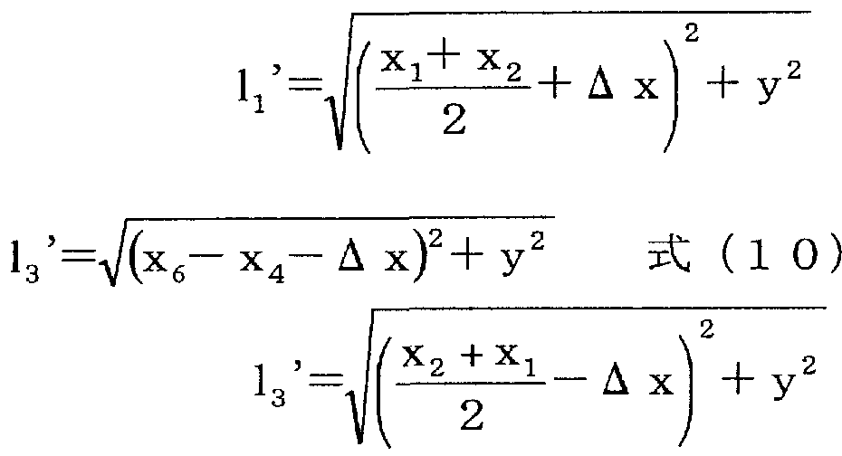
2 2 上記式(6)乃至(8)中、 Δχの符号は、図 15における左側の方向が正である。 2 2 In the above formulas (6) to (8), the sign of Δχ is positive in the left direction in FIG.
[0081] 2.上記式(6)乃至(8)の導出について
PIと P2は、面 B610より £巨離 y離れている。 [0081] 2. Derivation of the above equations (6) to (8) PI and P2 are far apart from plane B610.
[0082] P1は、反射面 A600より距離 X、また P2は反射面 A600より距離 X離れた位置に [0082] P1 is a distance X away from the reflective surface A600, and P2 is a distance X away from the reflective surface A600.
1 2 1 2
いる。 Yes.
[0083] また、 U1より反射面 A600を反射して P1に至るまでの距離 1と、 U2より直接 P1を 結んだ距離 1が同じとなる U1の反射面 A600からの距離 Xの位置は次式(9)で示さ [0083] The distance 1 from the reflection surface A600 reflected from U1 to P1 is the same as the distance 1 directly connecting P1 from U2, and the distance X from the reflection surface A600 of U1 is Indicated by (9)
3 3 3 3
れる。 It is.
[0084] [数 2] [0084] [Number 2]
― x— ― X—
χ 3,-― ^ · · · · ( 9 ) χ 3,-^ (9)
2 2
同様に、 U2より反射面 C620を反射して P2に至るまでの距離 1と、 U1より直接 P2 Similarly, the distance from U2 to the reflection surface C620 and reaching P2 is 1, and U2 directly from P2
4 Four
を結んだ距離 1が同じとなる U2の反射面 C620からの距離 Xは次式(10)で示される The distance X from the U2 reflecting surface C620 is expressed by the following equation (10).
2 4 twenty four
。なお、次式(10)において、 Xは、 P2と反射面 C620との間の距離であり、 Xは、 P1 . In the following equation (10), X is the distance between P2 and the reflecting surface C620, and X is P1
5 6 と反射面 C620とを間の距離である。 The distance between 5 6 and the reflective surface C620.
[0085] [数 3] [0085] [Equation 3]
X6~ Xi X 6 to X i
X ( 1 0 ) X (1 0)
2 2
距離 1と距離 1が等しくなるためには、式(13)を満足することが必要である。ここで In order for distance 1 and distance 1 to be equal, it is necessary to satisfy equation (13). here
2 3 twenty three
式(13)を導出するための式(11) , (12)は、前述した式(9)及び(10)を用いる。 The expressions (9) and (10) described above are used as the expressions (11) and (12) for deriving the expression (13).
[数 4] [Equation 4]
12= 13 を解くと Solving 1 2 = 1 3
x2+ x1 r= χΓ ( 1 3 )
また、 PIと P2の間の距離は同じなので、次式(14)が成り立つ。 x 2 + x 1 r = χ Γ (1 3) Also, since the distance between PI and P2 is the same, the following equation (14) holds.
[0087] X ― X =x ― X …、丄 4) [0087] X ― X = x ― X…, 丄 4)
6 5 2 1 6 5 2 1
したがって、上記式(13)と式(14)から以下の関係式(15), (16)が得られる。
Therefore, the following relational expressions (15) and (16) are obtained from the above expressions (13) and (14).
X =x -•(16) X = x-• (16)
6 2 6 2
一方、 P1から Δχだけずれた点 P1'において、 U1から反射面 Αに反射して P1'ま での距離 1 'と、 U2から直接 P1'までの距離 1 'とした場合、以下の関係式となる。 On the other hand, at the point P1 'that is shifted from P1 by Δχ, when the distance 1' from U1 to the reflecting surface し て 1 to P1 'and the distance 1' from U2 directly to P1 'is set as It becomes.
1 3 13
[0089] [数 5] [0089] [Equation 5]
'=^+ χ Δ x)2+ y2 式 (9) '= ^ + χ Δ x) 2 + y 2 formula (9)
、 (1 5) 及び (1 6) より
したがって、 PIから距離 Δχだけ X方向に移動した PI'における距離 1,と距離 1,の From (1 5) and (1 6) Therefore, the distance 1 and the distance 1 in PI 'moved in the X direction by a distance Δχ from PI
1 3 差 は、以下の関係式となる。 1 3 The difference is as follows.
[0090] [¾6] [0090] [¾6]
Δ Ι^し 13' より Δ Ι ^ し 1 3 '
Xj + x。 , +: Xj + x. , +:
.·. Δ L = Δ X + y2 -. 厶 X + y2 と式 (8) が求まる。 .. Δ L = Δ X + y 2- . 厶 X + y 2 and equation (8) are obtained.
2 2 twenty two
3.距離差が発生することによる到達時間のずれの補正 3. Correction of time lag due to distance difference
P1 'におレ、て U1から反射面 Aに反射して P1 'までの距離 1,と、 U2から直接 P1,ま At P1 ', the distance from U1 to reflection surface A to P1' is 1, and directly from U2 to P1,
1 1
での距離 1 'に差があると、 U1が発せられた音(例えば Rch音声)と U2から発せられ If there is a difference in the distance 1 'at U, the sound from U1 (eg Rch sound) and U2
3 Three
た音(例えば Lch音声)が同時に届かず、ずれてしまう。このときのずれる時間 ΔΤ [秒 ]は経路差 AL[m]と音速 S[m/s]から次式(17)のように求まる。なお、 ALには、符 号があるため ΔΤにも符号がある。 The sound (for example, Lch sound) does not reach at the same time and shifts. The deviation time ΔΤ [sec] at this time can be obtained from the path difference AL [m] and the sound velocity S [m / s] as shown in the following equation (17). Since AL has a sign, ΔΤ also has a sign.
[0091] △ T=AL/S [秒] ·'·(17)
したがって、このずれ ΔΤを補正するためには、第 1の Rチャンネルスピーカ 101か ら出力される音を他のスピーカ(第 2の Rチャンネルスピーカ 102から第 4の Lチャンネ ルスピーカ 104)力も出力される音より ΔΤ [秒]進める力、、または他のスピーカ(第 2の Rチャンネルスピーカ 102から第 4の Lチャンネルスピーカ 104)から出力される音を、 第 1の Rチャンネルスピーカ 101から出力される音より ΔΤ [秒]遅らせればよい。 [0091] △ T = AL / S [sec] · '· (17) Therefore, in order to correct this deviation ΔΤ, the sound output from the first R channel speaker 101 is also output from the power of the other speakers (from the second R channel speaker 102 to the fourth L channel speaker 104). Sound that is advanced ΔΤ [seconds] from the sound, or the sound output from the other speaker (the second R channel speaker 102 to the fourth L channel speaker 104), the sound output from the first R channel speaker 101 It should be delayed by ΔΤ [sec].
[0092] 以上、聴者位置が変わった場合の調整方法の各要素について説明した。以下、実 際のスピーカシステム 100 (図 1)に適用する場合について説明する。本実施の形態 は、図 16及び図 17に示す条件に従って調整が行われる。 In the above, each element of the adjustment method when the listener position is changed has been described. Hereinafter, a case where the present invention is applied to an actual speaker system 100 (FIG. 1) will be described. In the present embodiment, the adjustment is performed according to the conditions shown in FIGS.
[0093] 図 16A—Bは、スピーカシステム 100に適用する調整方法を説明する模式図、図 1 7は、聴者の位置(頭の位置)の位相差の制御内容を表にして示す図である。図 9と 同一構成部分には同一符号を付してレ、る。 [0093] FIGS. 16A and 16B are schematic diagrams for explaining an adjustment method applied to the speaker system 100, and FIG. 17 is a table showing the control content of the phase difference of the listener position (head position). . Components that are the same as those in FIG.
[0094] (1) 本実施の形態のスピーカシステム 100では、理論上消音となる Null面のずれ の調整を、スピーカユニット全体を回転させる「回転」ではなぐ図 13及び図 14で詳 述したスピーカの「仰角差」を用いて調整する。 (1) In the speaker system 100 according to the present embodiment, the speaker described in detail with reference to FIGS. 13 and 14 is not adjusted by “rotation” in which the entire speaker unit is rotated by adjusting the displacement of the null surface that is theoretically muted. Adjust using the “elevation difference”.
[0095] (2) 本実施の形態のスピーカシステム 100では、図 9に示す基準面 401に対し面 対称を維持したまま、基準面 401の角度を広めたり狭めたりする「開き角」の調整に 代えて、図 16Aに示すように、基準面 401に対して一方の第 1の Rチャンネルスピー 力 101のみの開き角を調整する「開き角 A450」制御を行う。 Lchについても同様に、 第 4の Lチャンネルスピーカ 104のみの開き角を調整する。 (2) In the speaker system 100 according to the present embodiment, the “opening angle” is adjusted to widen or narrow the angle of the reference surface 401 while maintaining the plane symmetry with respect to the reference surface 401 shown in FIG. Instead, as shown in FIG. 16A, “opening angle A450” control is performed to adjust the opening angle of only one first R channel speaker force 101 with respect to the reference plane 401. Similarly, for Lch, the opening angle of only the fourth L-channel speaker 104 is adjusted.
[0096] (3) 本実施の形態のスピーカシステム 100では、図 16Bに示すように、スピーカュ ニット全体の仰角を調整する「仰角 B460」制御を行う。 (3) In the speaker system 100 of the present embodiment, as shown in FIG. 16B, “elevation angle B460” control for adjusting the elevation angle of the entire speaker unit is performed.
[0097] したがって、スピーカユニット SP1 , SP2全体は、駆動用モータ 113, 123によって 仰角 B460制御される。また、スピーカユニット SP1 , SP2に載置される第 1の Rチャン ネルスピーカ 101と第 2の Rチャンネルスピーカ 102の仰角差、及び第 3の Lチャンネ ルスピーカ 103と第 4の Lチャンネルスピーカ 104の仰角差力 それぞれ駆動用モー タ 112, 122によって制卸される。 Therefore, the entire speaker units SP 1 and SP 2 are controlled by the elevation angle B 460 by the drive motors 113 and 123. Also, the elevation angle difference between the first R channel speaker 101 and the second R channel speaker 102 placed on the speaker units SP1 and SP2, and the elevation angle between the third L channel speaker 103 and the fourth L channel speaker 104. Differential force is controlled by driving motors 112 and 122, respectively.
[0098] このように、本実施の形態では、開き角 Α450と仰角 Β460のみを調整する。開き角 Α450と仰角 Β460のみを調整する方法を採ることで、機構の複雑度を減らしコスト低
減を図ること力 Sできる。また、回転による理論上消音となる Null軸を調整する範囲より も、開き角を調整しサイドガラス 210, 220により反射してくる経路を調整する方が効 果が高い。 Thus, in the present embodiment, only the opening angle Α450 and the elevation angle Β460 are adjusted. By adjusting only the opening angle Α450 and elevation angle Β460, the complexity of the mechanism is reduced and the cost is reduced. Power S can be reduced. In addition, it is more effective to adjust the opening angle and adjust the path reflected by the side glasses 210 and 220 than to adjust the null axis, which is theoretically silenced by rotation.
[0099] 本実施の形態では、仰角差をつけることによって理論上消音となる Null面の傾きを 制御する。したがって、実際のシステムのように動きに制限力 Sかかる場合、仰角 B460 を聴者に対しやや下又は上にずらし、仰角差を、図 17に示す表に従って調整するこ とで理論上消音となる Null面を聴者の位置に合わせる。このとき、スピーカユニットの 指向軸上に聴者を配置した場合、位相差をつけても理論上消音となる Null面を調整 できないので注意が必要である。なお、図 17の表の位相差の正負の定義について、 「正」とは、外側のスピーカ 101又は 104の仰角が内側のスピーカ 102又は 103の仰 角より大きいことを示し、「負」とは外側のスピーカ 101又は 104の仰角が内側のスピ 一力 102又は 103の仰角より小さいことを示す。 [0099] In the present embodiment, the inclination of the null surface that is theoretically muffled is controlled by giving an elevation angle difference. Therefore, when the limit force S is applied to the movement as in the actual system, the elevation angle B460 is shifted slightly downward or upward with respect to the listener, and the elevation angle difference is adjusted according to the table shown in Fig. 17. Align the face with the listener. At this time, if the listener is placed on the directivity axis of the speaker unit, it should be noted that the null surface, which theoretically silences even if a phase difference is added, cannot be adjusted. Regarding the definition of positive / negative phase difference in the table of FIG. 17, “positive” means that the elevation angle of the outer speaker 101 or 104 is larger than the elevation angle of the inner speaker 102 or 103, and “negative” means It indicates that the elevation angle of the outer speaker 101 or 104 is smaller than the elevation angle of the inner spin force 102 or 103.
[0100] 図 18は、スピーカシステム 100における自動調整処理を示すフローチャートである 。本フローは、制御部 150内部の CPUにより所定タイミング周期で繰り返し実行され る。また、本フローは、聴者 P1の位置の移動を例に採っている力 S、聴者 P2の位置の 移動につ!/、ても同様の調整処理を実行する。 FIG. 18 is a flowchart showing an automatic adjustment process in the speaker system 100. This flow is repeatedly executed at a predetermined timing cycle by the CPU in the control unit 150. In addition, this flow executes the same adjustment process for the force S taking the movement of the position of the listener P1 as an example and the movement of the position of the listener P2.
[0101] 聴者 P1の位置変化により本プログラムはスタートし(ステップ S1)、ステップ S 11で 聴者 P1の位置の移動が前後か否かを判別する。聴者 P1の位置の移動は、位置検 出部 160 (図 2参照)からの聴者の頭部位置情報を取得することにより判定する。聴 者 P1が前後方向に移動する代表例は、聴者 P1が座席を前又は後に移動したり、座 席のリクライニング角度を変えたりする場合である。また、後述する聴者 P1の左右位 置の移動は、座席に設置された接点スィッチ 161 , 162からの信号だけでは検出し にくいが、座席背に接点スィッチを増やすなどの対応により検出は可能である。また 、接点スィッチなどの位置検出に代えて、聴者の頭部近傍を撮像するカメラと画像処 理部による位置検出手段を用いれば、より精度良く聴者の頭部位置情報を取得でき る。なお、聴者 P1が運転席の運転者である場合、左右方向への移動は少ないものと 考えられる。また、斜めの移動についても前後位置の移動を伴っており前後位置の 移動に含まれる。
[0102] 上記ステップ SI 1で聴者 PIの位置の移動が前後の場合は、ステップ S12で Null 面の調整を行う。制御部 150は、聴者 P1の前後位置の移動量に基づいて、聴者 P1 の位置を Null面上に置くための Null面調整の演算を行い、演算結果を制御パラメ ータに変換してモータドライバ部 130に出力する。モータドライバ部 130は、制御部 1 50からの制御コマンドを基に該当する駆動用モータ(ここでは駆動用モータ 112)を 、 目標値になるよう駆動する。 Null面の調整は、前述したように「回転」と「仰角差」を 変化させる 2つの方法がある力 S、本実施の形態では「仰角差」を変化させて Null面を 調整する。制御部 150は、モータドライバ部 130に、スピーカ 101乃至 104及びスピ 一力ユニット SP1 , SP2の開き角、仰角差及び仰角を制御する制御コマンドを送信し ている。この制御コマンドのうち、「仰角差」を示す目標値を供給することで、モータド ライバ部 130は、駆動用モータ 112を所定量駆動して、第 1の Rチャンネルスピーカ 1 01の指向軸と第 2の Rチャンネルスピーカ 102の指向軸との間で仰角差を生じさせ、 Null面を傾けることによって(図 14参照)、聴者 P1の移動位置に Null面を置くことが できる。 [0101] This program starts when the position of the listener P1 changes (step S1). In step S11, it is determined whether or not the position of the listener P1 has moved back and forth. The movement of the position of the listener P1 is determined by acquiring the listener's head position information from the position detection unit 160 (see FIG. 2). A typical example of listener P1 moving in the front-rear direction is when listener P1 moves forward or backward from the seat or changes the reclining angle of the seat. In addition, the movement of the left and right positions of the listener P1, which will be described later, is difficult to detect only by signals from the contact switches 161 and 162 installed in the seat, but can be detected by measures such as increasing the contact switch on the back of the seat. . Also, instead of detecting the position of the contact switch or the like, the position of the listener's head can be obtained with higher accuracy by using a camera that captures the vicinity of the head of the listener and a position detection means using an image processing unit. When listener P1 is a driver in the driver's seat, it is considered that there is little movement in the left-right direction. In addition, the oblique movement is accompanied by the movement of the front and rear position, and is included in the movement of the front and rear position. [0102] If the position of the listener PI moves back and forth in step SI 1 above, the null plane is adjusted in step S12. Based on the amount of movement of the front and rear positions of the listener P1, the control unit 150 performs a null surface adjustment calculation to place the position of the listener P1 on the null surface, converts the calculation result into control parameters, and converts the calculation result into a motor driver. Output to part 130. The motor driver unit 130 drives the corresponding drive motor (in this case, the drive motor 112) based on the control command from the control unit 150 so as to reach the target value. As described above, there are two methods for adjusting the Null surface, the force S having two methods of changing the “rotation” and the “elevation angle difference”. In this embodiment, the “Elevation angle difference” is changed to adjust the Null surface. The control unit 150 transmits to the motor driver unit 130 control commands for controlling the opening angles, the elevation angle differences, and the elevation angles of the speakers 101 to 104 and the spin force units SP1 and SP2. By supplying a target value indicating the “elevation angle difference” among the control commands, the motor driver unit 130 drives the driving motor 112 by a predetermined amount, and the directivity axis of the first R-channel speaker 101 and the first axis. The null plane can be placed at the moving position of the listener P1 by creating an elevation angle difference with the directional axis of the second R channel speaker 102 and tilting the null plane (see Fig. 14).
[0103] 次いで、ステップ S13でスピーカユニット SP1において開き角を変化させ、反射して 聴者 P1に届く音の音質が良くなるように調整する反射音の調整を行う。この調整の 判断基準には、音圧、歪み、周波数特性などがある。制御部 150は、あらかじめ内部 メモリ内に、聴者 P1の位置と聴者 P1への反射音が最もよく聞こえる開き角との関係を テーブルとして保持しており、このテーブルを参照して開き角を変える。本実施の形 態における開き角とは、図 16に示す第 1の Rチャンネルスピーカ 101のみの開き角の 調整である。モータドライバ部 130は、駆動用モータ 111を所定量駆動して、第 1の R チャンネルスピーカ 101の開き角を変えて、反射音の調整を行う。ここまでの処理に より、図 5に示す前後への変化時のように、 Null面が調整され、反射音の調整が行わ れる。 [0103] Next, in step S13, the opening angle is changed in the speaker unit SP1, and the reflected sound is adjusted so as to improve the quality of the sound reflected and reaching the listener P1. The criteria for this adjustment include sound pressure, distortion, and frequency characteristics. The control unit 150 stores in advance in the internal memory a relationship between the position of the listener P1 and the opening angle at which the reflected sound to the listener P1 is best heard, and changes the opening angle with reference to this table. The opening angle in the present embodiment is an adjustment of the opening angle of only the first R channel speaker 101 shown in FIG. The motor driver unit 130 drives the driving motor 111 by a predetermined amount, changes the opening angle of the first R channel speaker 101, and adjusts the reflected sound. Through the processing up to this point, the null surface is adjusted and the reflected sound is adjusted as in the case of the forward / backward change shown in FIG.
[0104] 次いで、ステップ S14で聴者 P1の位置における左右音量差を調整してステップ S2 1に進む。上記開き角の制御により反射音(ここでは Rch)については調整が済んだ 1S 反射音 (Rch)について調整したことにより、反射音 (Rch)に対応する直接音(Lc h)についても調整が必要になる。そこで、及び第 3の Lチャンネルスピーカ 103の音
量を変化させ、左右の音量が同じになるように調整する。制御部 150は、スピーカ 10 1乃至 104の出力音量及び出力音の位相を制御する制御コマンドを音響処理部 14 1に出力している。制御部 150は、音響処理部 141に第 3の Lチャンネルスピーカ 10 3の音量を変える制御コマンドを出力して第 3の Lチャンネルスピーカ 103の音量を変 化させ、左右の音量が同じになるように調整する。 [0104] Next, in step S14, the left-right volume difference at the position of the listener P1 is adjusted, and the process proceeds to step S21. The reflected sound (Rch) has been adjusted by controlling the opening angle. By adjusting the 1S reflected sound (Rch), the direct sound (Lch) corresponding to the reflected sound (Rch) must also be adjusted. become. Therefore, and the sound of the third L-channel speaker 103 Adjust the volume so that the left and right volume are the same. The control unit 150 outputs a control command for controlling the output volume and the phase of the output sound of the speakers 101 to 104 to the acoustic processing unit 141. The control unit 150 outputs a control command for changing the volume of the third L-channel speaker 103 to the acoustic processing unit 141 to change the volume of the third L-channel speaker 103 so that the left and right volume are the same. Adjust to.
[0105] 上記ステップ S 11乃至ステップ S 14の処理を、処理 Aという。 [0105] The processing from step S11 to step S14 is referred to as processing A.
[0106] 上記ステップ S11で聴者 P1の位置の移動が前後でないとき、あるいは上記ステツ プ S14の処理を行ったとき、ステップ S21で聴者 P1の位置の移動が左右か否かを判 別する。聴者 P1の位置の移動が左右の場合は、ステップ S22で左右の経路差を補 正する。具体的には、スピーカユニット SP1を構成する第 1の Rチャンネルスピーカ 1 01からの出力音の位相を、その他のスピーカ 102乃至 104のそれに対して進めたり 遅らせたりすることで左右経路差を調整する。図 6に示すように、聴者 P1の位置が左 右方向に変化した場合には、スピーカから聴者 P1までの左右の経路長は大きく変わ り左右経路差が生じる。左右経路差は左右の音の到達時間の差となり左右の音のず れとなる。このステップ S22では、左右経路差を、出力音の位相を変えることで調整 する。 [0106] When the movement of the position of the listener P1 is not back and forth in the above step S11, or when the processing of the above step S14 is performed, it is determined whether or not the movement of the position of the listener P1 is right or left in the step S21. If the movement of the listener P1 is right or left, the left and right path difference is corrected in step S22. Specifically, the left / right path difference is adjusted by advancing or delaying the phase of the output sound from the first R channel speaker 101 constituting the speaker unit SP1 relative to that of the other speakers 102 to 104. . As shown in Fig. 6, when the position of the listener P1 changes to the left and right, the left and right path length from the speaker to the listener P1 changes greatly, resulting in a difference between the left and right paths. The left / right path difference is the difference between the arrival times of the left and right sounds, and the left and right sounds are shifted. In step S22, the left / right path difference is adjusted by changing the phase of the output sound.
[0107] 次いで、ステップ S23で Null面の調整を行う。調整方法は、上記ステップ S 12の場 合と同様である。但し、左右方向への変化時は、図 6に示すように、前後への変化時 と比べて Null面は左右に大きく移動するので、大きな調整が必要である。 [0107] Next, in step S23, the null surface is adjusted. The adjustment method is the same as in step S12 above. However, when changing to the left and right, as shown in Fig. 6, the Null surface moves more to the left and right compared to when changing to the front and back, so a great adjustment is required.
[0108] 次いで、ステップ S24でスピーカユニット SP1において開き角を変化させ、反射して 聴者 P1に届く音の音質が良くなるように調整する反射音の調整を行う。調整方法は 、上記ステップ S 13の場合と同様である。 [0108] Next, in step S24, the opening angle is changed in the speaker unit SP1, and the reflected sound is adjusted so as to improve the quality of the sound reflected and reaching the listener P1. The adjustment method is the same as in step S13.
[0109] 次いで、ステップ S25で聴者 P1の位置における左右音量差を調整してステップ S3 1に進む。調整方法は、上記ステップ S14の場合と同様である。 [0109] Next, in step S25, the left-right volume difference at the position of the listener P1 is adjusted, and the process proceeds to step S31. The adjustment method is the same as in step S14.
[0110] 上記ステップ S21乃至ステップ S25の処理を、処理 Bという。 [0110] The processing from step S21 to step S25 is referred to as processing B.
[0111] 上記ステップ S21で聴者 P1の位置の移動が左右でないとき、あるいは上記ステツ プ S25の処理を行ったとき、ステップ S31で Null面の調整を行う。調整方法は、上記 ステップ S 12の場合と同様である。この場合の Null面の調整量は小さい。
[0112] 次いで、ステップ S32でスピーカユニット SP1において開き角を変化させ、反射して 聴者 P1に届く音の音質が良くなるように調整する反射音の調整を行う。調整方法は 、上記ステップ S 13の場合と同様である。 [0111] When the movement of the position of the listener P1 is not left or right in step S21, or when the process of step S25 is performed, the null plane is adjusted in step S31. The adjustment method is the same as in step S12 above. In this case, the amount of adjustment on the null surface is small. [0112] Next, in step S32, the opening angle is changed in the speaker unit SP1, and the reflected sound is adjusted so as to improve the quality of the sound reflected and reaching the listener P1. The adjustment method is the same as in step S13.
[0113] 次いで、ステップ S33で聴者 P1の位置における左右音量差を調整し、ステップ S3 4で聴者 P2の位置における左右音量差を調整して本フローを終了する。聴者 P1の 位置が上下すると、調整が済んだ一方のスピーカ(第 1の Rチャンネルスピーカ 101) と他方のスピーカ(第 3の Lチャンネルスピーカ 103)とで聴者 P1に対する指向軸に 差が生じる。そこでステップ S33では、この左右音量差を、スピーカュュット SP2の内 側のスピーカ(第 3の Lチャンネルスピーカ 103)の音量を変化させることで、聴者 P1 について左右チャンネルの音量が同じになるように調整する。同様に、ステップ S34 では、左右音量差を、スピーカユニット SP1の内側のスピーカ(第 2のすチャンネルス ピー力 102)の音量を変化させることで、聴者 P2について左右チャンネルの音量が 同じになるように調整する。 Next, in step S33, the left / right volume difference at the position of the listener P1 is adjusted, and in step S34, the left / right volume difference at the position of the listener P2 is adjusted, and this flow is finished. When the position of the listener P1 moves up and down, a difference occurs in the directivity axis with respect to the listener P1 between the one speaker (first R channel speaker 101) and the other speaker (third L channel speaker 103) that have been adjusted. Therefore, in step S33, this left and right volume difference is adjusted so that the volume of the left and right channels is the same for the listener P1 by changing the volume of the inner speaker (third L channel speaker 103) of the speaker unit SP2. . Similarly, in step S34, the volume of the left and right channels is made the same for listener P2 by changing the volume of the left and right volume by changing the volume of the speaker inside the speaker unit SP1 (second channel speaker power 102). Adjust to.
[0114] 上記ステップ S31乃至ステップ S34の処理を、処理 Cという。 [0114] The processing from step S31 to step S34 is referred to as processing C.
[0115] 上記処理 A、処理 B、及び処理 Cの実行順番は入れ替え可能である。また、本フロ 一の実行タイミングは任意である。例えば、聴者の位置が所定以上変化したときにプ ログラムを開始してもよいし、常時実行しリアルタイムで調整してもよい。さらには、聴 者が着座したとき、音響入力があつたとき、又は音響機器に通電されたときなどに自 動実行する態様でもよい。勿論、聴者の指示により実行してもよいことは言うまでもな い。 [0115] The execution order of process A, process B, and process C can be interchanged. The execution timing of this flow is arbitrary. For example, the program may be started when the listener's position changes by more than a predetermined value, or may be always executed and adjusted in real time. Further, it may be automatically executed when a listener is seated, when an acoustic input is received, or when an acoustic device is energized. Of course, it may be performed according to the instruction of the listener.
[0116] 以上詳細に説明したように、本実施の形態によれば、スピーカシステム 100は、第 1 の聴取位置で聴取される音を出力する第 1の Rチャンネルスピーカ 101と、第 2の聴 取位置で聴取される音を出力する第 2の Rチャンネルスピーカ 102とを含む第 1のス ピー力ユニット SP1と、第 1の聴取位置で聴取される音を出力する第 3の Lチャンネル スピーカ 103と、第 2の聴取位置で聴取される音を出力する第 4の Lチャンネルスピー 力 104とを含む第 2のスピーカユニット SP2と、第 1の Rチャンネルスピーカ 101とその 指向軸との交点と、第 2の Rチャンネルスピーカ 102とその指向軸との交点とを結ぶ 線の垂直二等分面に、現在の第 1の聴取位置が実質的に含まれるよう、少なくとも第
1の Rチャンネルスピーカ 101を駆動し、さらに、第 3の Lチャンネルスピーカ 103とそ の指向軸との交点と、第 4の Lチャンネルスピーカ 104とその指向軸との交点とを結ぶ 線の垂直二等分面に、現在の第 2の聴取位置が実質的に含まれるよう、少なくとも第 4の Lチャンネルスピーカ 104を駆動する駆動用モータ 111乃至 113, 121乃至 123 及びそのモータドライバ部 130とを備えている。この構成により、聴者の位置が前後 方向,左右方向又は上下方向に移動しても、本スピーカシステム 100は、現在の聴 取位置に合うように少なくとも各スピーカ 101乃至 104の向き等を自動調整すること ができる。これによつて、複数の聴者に違和感を与えないリスニング環境を同時に提 供可能なスピーカシステムを実現することができる。すなわち、車両の車室内に 2人 の聴者がいる環境において、 2人の聴者に対して、それぞれの聴取位置にかかわら ず同時に(1)音像が正面に定位される、(2)広いステレオ感を提供できる、(3) Rチヤ ンネルの音と Lチャンネルの音とが同時に到来する、という優れた効果を得ることがで き、最適な音響環境を実現することができる。 [0116] As described in detail above, according to the present embodiment, the speaker system 100 includes the first R channel speaker 101 that outputs the sound heard at the first listening position, and the second listening sound. A first speaker unit SP1 including a second R-channel speaker 102 that outputs a sound heard at the listening position, and a third L-channel speaker 103 that outputs the sound heard at the first listening position. A second speaker unit SP2 including a fourth L-channel speaker power 104 that outputs a sound heard at the second listening position, an intersection of the first R-channel speaker 101 and its directional axis, At least the first listening position is substantially included in the vertical bisector of the line connecting the second R-channel speaker 102 and the intersection of its directional axis. 1 R-channel speaker 101 is driven, and the vertical line between the intersection of the third L-channel speaker 103 and its directional axis and the intersection of the fourth L-channel speaker 104 and its directional axis Driving motors 111 to 113, 121 to 123 for driving at least the fourth L-channel speaker 104 and motor driver section 130 thereof are provided so that the current second listening position is substantially included on the equal dividing plane. ing. With this configuration, even if the position of the listener moves in the front-rear direction, the left-right direction, or the up-down direction, the present speaker system 100 automatically adjusts at least the orientation of each speaker 101 to 104 so as to match the current listening position. be able to. As a result, it is possible to realize a speaker system that can simultaneously provide a listening environment that does not cause discomfort to a plurality of listeners. In other words, in an environment where there are two listeners in the vehicle cabin, (1) the sound image is localized in front of the two listeners at the same time regardless of their listening position. It can provide an excellent effect that (3) the sound of the R channel and the sound of the L channel arrive at the same time, and an optimal acoustic environment can be realized.
[0117] また、本実施の形態では、理論上消音となる Null面の向きを変える場合、第 2の R チャンネルスピーカ 102に対する第 1の Rチャンネルスピーカ 101の仰角差と、第 3の Lチャンネルスピーカ 102に対する第 4の Lチャンネルスピーカ 104の仰角差とをそれ ぞれ用いて調整しているので、第 2の Rチャンネルスピーカ 102及び第 3の Lチャンネ ノレスピーカ 103を固定的に設置しておくことができ、低コストで実施することができる 効果がある。 [0117] Further, in this embodiment, when changing the direction of the null surface that is theoretically silenced, the elevation angle difference of the first R-channel speaker 101 with respect to the second R-channel speaker 102 and the third L-channel speaker Therefore, the second R-channel speaker 102 and the third L-channel speaker 103 can be fixedly installed. Can be implemented at low cost.
[0118] (実施の形態 2) [0118] (Embodiment 2)
実施の形態 1では、理論上消音となる Null面のずれの調整をスピーカの「仰角差」 を用いて調整する例について説明した。本実施の形態は、 Null面のずれをスピーカ ユニット全体を回転させる「回転」により調整する。また、スピーカユニット全体を回転 させる「回転」により調整することで、より精密な調整を可能にする。 In the first embodiment, an example has been described in which the adjustment of the shift of the null surface, which is theoretically muted, is adjusted using the “elevation angle difference” of the speaker. In this embodiment, the deviation of the null surface is adjusted by “rotation” that rotates the entire speaker unit. In addition, more precise adjustments can be made by adjusting the “rotation” that rotates the entire speaker unit.
[0119] 図 19は、本発明の実施の形態 2に係るスピーカシステム 700及びそれを搭載する 車両内を上方から見た模式図、図 20は、図 19に示すスピーカシステム 700及びそ の周辺の構成を示すブロック図である。本実施の形態の説明にあたり、図 1及び図 2 と同一構成部分には同一符号を付して重複箇所の説明を省略する。
[0120] 図 19及び図 20において、スピーカシステム 700は、開き角を変える駆動用モータ 1 11 , 121 , 714, 724、スピーカユニット SPの回転を変える駆動用モータ 712, 722、 スピーカユニット SPの仰角を変える駆動用モータ 113及び 123を駆動するモータドラ ィバ部 730と、 2チャンネル (Lチャンネルと Rチャンネル)信号から構成される音響ソ ースが入力される音入力部 140からの 2チャンネル信号を信号処理して、上述の正 相信号 (R)、逆相信号 (R)、正相信号 (L)及び逆相信号 (L)を生成する音響処理部 141とを備える。 FIG. 19 is a schematic view of the speaker system 700 according to Embodiment 2 of the present invention and the vehicle in which the speaker system 700 is mounted, as viewed from above. FIG. 20 is a schematic view of the speaker system 700 shown in FIG. It is a block diagram which shows a structure. In the description of the present embodiment, the same components as those in FIG. 1 and FIG. In FIG. 19 and FIG. 20, the speaker system 700 includes a drive motor 1 11, 121, 714, 724 that changes the opening angle, a drive motor 712, 722 that changes the rotation of the speaker unit SP, and the elevation angle of the speaker unit SP. Motor driver unit 730 that drives motors 113 and 123 for changing the sound, and two-channel signals from the sound input unit 140 to which an acoustic source composed of two-channel (L channel and R channel) signals is input. And an acoustic processing unit 141 that performs signal processing to generate the above-described normal phase signal (R), negative phase signal (R), normal phase signal (L), and negative phase signal (L).
[0121] 図 20において、車両には、スピーカシステム 700に対して、複数の聴者の聴者位 置に応じて、開き角等を制御する制御部 750と、座席の前後位置及び傾き角を検出 する接点スィッチ 161及び 162からの信号を受けて着座した聴者の頭部位置を検出 する位置検出部 160が備わる。 [0121] In FIG. 20, the vehicle detects a front-rear position and an inclination angle of the seat, and a control unit 750 that controls an opening angle and the like according to the listener positions of a plurality of listeners with respect to the speaker system 700. A position detector 160 for detecting the head position of the seated listener in response to signals from the contact switches 161 and 162 is provided.
[0122] 制御部 750は、マイクロプロセッサからなり図 21で後述する制御プログラムを実行 することにより、位置検出部 160からの聴者の頭部位置情報を取得し、現在の第 1又 は第 2の聴者位置に応じて、スピーカ 101乃至 104及びスピーカユニット SP1 , SP2 の開き角、回転及び仰角を制御する制御コマンドをモータドライバ部 730に出力する とともに、スピーカ 101乃至 104からの出力音量、及び出力音の位相を制御する制 御信号を音響処理部 141に出力する。モータドライバ部 730は、上記制御コマンドに 従って対応する駆動用モータの駆動量を精密に制御し、スピーカ 101乃至 104及び スピーカユニット SP1 , SP2の開き角、回転及び仰角を現在の値から目標値に変える 。また、音響処理部 141は、制御部 750からの制御信号に従ってスピーカ 101乃至 1 04からの出力音量及び出力音の位相を変える。音響処理部 141による音量及び位 相の制御は、駆動用モータによりスピーカ 101乃至 104の開き角、並びにスピーカュ ニット SP1 , SP2の回転及び仰角を変えたことによる音圧レベルと位相のずれを調整 するためのものである。 [0122] The control unit 750 is formed of a microprocessor and acquires a listener's head position information from the position detection unit 160 by executing a control program described later with reference to FIG. Control commands for controlling the opening angle, rotation, and elevation angle of the speakers 101 to 104 and the speaker units SP1 and SP2 are output to the motor driver unit 730 according to the listener position, and the output volume and output sound from the speakers 101 to 104 are output. A control signal for controlling the phase of the sound is output to the acoustic processing unit 141. The motor driver unit 730 precisely controls the driving amount of the corresponding driving motor in accordance with the control command, and changes the opening angle, rotation, and elevation angle of the speakers 101 to 104 and speaker units SP1 and SP2 from the current values to the target values. Change. In addition, the acoustic processing unit 141 changes the output volume and the phase of the output sound from the speakers 101 to 104 in accordance with the control signal from the control unit 750. The sound processing unit 141 controls the volume and phase by adjusting the sound pressure level and the phase shift caused by changing the opening angles of the speakers 101 to 104 and the rotation and elevation angles of the speaker units SP1 and SP2 by the driving motor. Is for.
[0123] 図 21は、本スピーカシステム 700の自動調整処理を示すフローチャートである。本 フローは、制御部 750内部の CPUにより所定タイミング周期で繰り返し実行される。 図 18に示すフローと同一処理を行うステップには同一符号を番号を付している。また 、相違するステップのステップ番号には、「A」を付している。
[0124] また、本フローは、聴者 P1の位置の移動を例に採っている力 聴者 P2の位置の移 動につ!/、ても同様の調整処理を実行する。 FIG. 21 is a flowchart showing an automatic adjustment process of the speaker system 700. This flow is repeatedly executed at a predetermined timing cycle by the CPU in the control unit 750. Steps that perform the same processing as the flow shown in FIG. 18 are given the same reference numerals. Further, “A” is added to the step numbers of the different steps. [0124] In addition, this flow executes the same adjustment process even if the movement of the position of the listener P2 is taken as an example of the movement of the position of the listener P1.
[0125] 聴者 P1の位置変化により本プログラムはスタートし(ステップ S1)、ステップ S 11で 聴者 P1の位置の移動が前後か否かを判別する。聴者 P1の位置の移動は、位置検 出部 160 (図 20参照)からの聴者の頭部位置情報を取得により判定する。聴者 P1の 位置の移動が前後の場合は、ステップ S 12Aで Null面の調整を行う。制御部 750は 、聴者 P1の前後位置の移動量に基づいて、第 1の聴取位置を Null面上に置くため の Null面調整の演算を行!/、、演算結果を制御パラメータに変換してモータドライバ 部 730に出力する。モータドライバ部 730は、制御部 750からの制御コマンドを基に 該当する駆動用モータ(ここでは駆動用モータ 712)をこの目標値になるよう駆動する 。 Null面の調整は、スピーカユニット SP2を「回転」を変化させて Null面を調整する。 回転による Null面の調整は、 Null面を Null軸を基準に傾ける「仰角差」を用いる場 合よりも要求精度を確保できる点で優れている。また、スピーカユニット SP2を「回転」 を変化させることは、左右の音量差をより細かに調整できる点で効果がある。 [0125] This program starts when the position of the listener P1 changes (step S1). In step S11, it is determined whether or not the position of the listener P1 has moved back and forth. The movement of the position of the listener P1 is determined by acquiring the listener's head position information from the position detection unit 160 (see FIG. 20). If the position of the listener P1 is back and forth, adjust the null plane in step S12A. Based on the amount of movement of the front and rear position of the listener P1, the control unit 750 calculates the null surface adjustment to place the first listening position on the null surface! /, And converts the calculation result into control parameters. Output to motor driver 730. The motor driver unit 730 drives the corresponding drive motor (in this case, the drive motor 712) based on the control command from the control unit 750 so as to reach this target value. To adjust the null surface, change the “rotation” of the speaker unit SP2 and adjust the null surface. Adjustment of the null surface by rotation is superior in that the required accuracy can be ensured compared to using an “elevation difference” in which the null surface is tilted with respect to the null axis. Also, changing the “rotation” of the speaker unit SP2 is effective in that the difference in volume between the left and right can be adjusted more finely.
[0126] 次いで、ステップ S13Aでスピーカユニット SP1において開き角を変化させ、反射し て聴者 P1に届く音の音質が良くなるように調整する反射音の調整を行う。この調整の 判断基準には、音圧、歪み、周波数特性などがある。制御部 750は、あらかじめ内部 メモリ内に、聴者 P1の位置と聴者 P1への反射音が最もよく聞こえる開き角との関係を テーブルとして保持しており、このテーブルを参照して開き角を変える。本実施の形 態における開き角とは、図 16に示す第 1の Rチャンネルスピーカ 101と、第 2の Lチヤ ンネルスピーカ 102の開き角の調整である。モータドライバ部 730は、駆動用モータ 1 11を所定量駆動して、第 1の Rチャンネルスピーカ 101及び第 2の Lチャンネルスピ 一力 102の開き角を変えて、反射音の調整を行う。 [0126] Next, in step S13A, the opening angle is changed in the speaker unit SP1, and the reflected sound is adjusted so as to improve the quality of the sound that is reflected and reaches the listener P1. The criteria for this adjustment include sound pressure, distortion, and frequency characteristics. The control unit 750 previously stores in the internal memory a relationship between the position of the listener P1 and the opening angle at which the reflected sound to the listener P1 is best heard, and changes the opening angle with reference to this table. The opening angle in the present embodiment is adjustment of the opening angle of first R channel speaker 101 and second L channel speaker 102 shown in FIG. The motor driver unit 730 drives the driving motor 111 by a predetermined amount, changes the opening angle of the first R channel speaker 101 and the second L channel force 102, and adjusts the reflected sound.
[0127] 次いで、ステップ S14で聴者 P1の位置における左右音量差を調整し、ステップ S1 5で聴者 P2の位置における左右音量差を調整してステップ S21に進む。上記開き角 の制御により反射音(ここでは Rch)については調整が済んだが、反射音 (Rch)につ いて調整したことにより、反射音 (Rch)に対応する直接音(Lch)についても調整が 必要になる。そこで、スピーカユニット SP2の開き角及び第 3の Lチャンネルスピーカ 1
03の音量を変化させ、聴者 P1について左右チャンネルの音量が同じになるように調 整する。さらに、聴者 P2についても左右チャンネルの音量が同じになるように、第 2の Rチャンネルスピーカ 102及び/又は第 4の Lチャンネルスピーカ 104の音量が調整 される。制御部 750は、スピーカ 101乃至 104の出力音量及び出力音の位相を制御 する制御コマンドを音響処理部 141に出力している。制御部 750は、音響処理部 14 1に第 3の Lチャンネルスピーカ 103の音量を変える制御コマンドを出力して第 3の L チャンネルスピーカ 103の音量を変化させ、左右の音量が同じになるように調整する 。実施の形態 1では、スピーカユニットの「回転」を用いていないので、聴者 P2につい ては、聴者 P1の位置における左右音量差を調整後にスピーカユニット SP1及び第 3 の Lチャンネルスピーカ 103の音量調整に合わせる、調整し力、行えな力、つた力 本実 施の形態では、 Null面の調整のために用いる「回転」を、スピーカユニット SP2の指 向軸(それに伴う音量レベル,スピーカ特性)を調整することにも用いることで、更なる 音響効果を向上を図っている。 [0127] Next, in step S14, the left / right volume difference at the position of the listener P1 is adjusted, and in step S15, the left / right volume difference at the position of the listener P2 is adjusted, and the process proceeds to step S21. Although the reflected sound (Rch) has been adjusted by controlling the opening angle, the direct sound (Lch) corresponding to the reflected sound (Rch) can be adjusted by adjusting the reflected sound (Rch). I need it. Therefore, the opening angle of the speaker unit SP2 and the third L channel speaker 1 Change the volume of 03 and adjust the volume of the left and right channels for listener P1 to be the same. Further, the volume of the second R channel speaker 102 and / or the fourth L channel speaker 104 is adjusted so that the volume of the left and right channels is the same for the listener P2. The control unit 750 outputs a control command for controlling the output volume of the speakers 101 to 104 and the phase of the output sound to the acoustic processing unit 141. The control unit 750 outputs a control command for changing the volume of the third L-channel speaker 103 to the sound processing unit 141 to change the volume of the third L-channel speaker 103 so that the left and right volume are the same. adjust . Since Embodiment 1 does not use “rotation” of the speaker unit, the listener P2 adjusts the volume of the speaker unit SP1 and the third L-channel speaker 103 after adjusting the left-right volume difference at the position of the listener P1. In this embodiment, the “rotation” used to adjust the null surface is adjusted to the direction axis of the speaker unit SP2 (volume level and speaker characteristics associated therewith). This is also used to improve the sound effect.
[0128] 上記ステップ S 11乃至ステップ S 154の処理を、処理 Aという。 [0128] The processing from step S11 to step S154 is referred to as processing A.
[0129] 上記ステップ S11で聴者 P1の位置の移動が前後でないとき、あるいは上記ステツ プ S15の処理を行ったとき、ステップ S21で聴者 P1の位置の移動が左右か否かを判 別する。聴者 P1の位置の移動が左右の場合は、ステップ S22で左右の経路差を補 正する。具体的には、スピーカユニット SP1の第 1の Rチャンネルスピーカ 101からの 出力音の位相を、その他のスピーカ 102乃至 104のそれに対して進めたり遅らせたり することで左右経路差を位相を変えることで調整する。 [0129] When the movement of the position of the listener P1 is not back and forth in the above step S11, or when the process of the above step S15 is performed, it is determined in step S21 whether the movement of the position of the listener P1 is left or right. If the movement of the listener P1 is right or left, the left and right path difference is corrected in step S22. Specifically, by changing the phase of the left-right path difference by advancing or delaying the phase of the output sound from the first R channel speaker 101 of the speaker unit SP1 relative to that of the other speakers 102 to 104. adjust.
[0130] 次いで、ステップ S23Aで Null面の調整を行う。調整方法は、上記ステップ S12A の場合と同様に「回転」を用いる。左右方向への変化時は、前後への変化時と比べ て Null面は左右に大きく移動するので、「回転」を用いるとより調整が容易である。 [0130] Next, the null surface is adjusted in step S23A. As the adjustment method, “rotation” is used as in step S12A. When changing to the left and right, the Null surface moves more to the left and right than when changing to the front and back, so adjustment is easier with “rotation”.
[0131] 次いで、ステップ S24でスピーカユニット SP1において開き角を変化させ、反射して 聴者 P1に届く音の音質が良くなるように調整する反射音の調整を行う。調整方法は 、上記ステップ S13Aの場合と同様である。 [0131] Next, in step S24, the opening angle is changed in the speaker unit SP1, and the reflected sound is adjusted so as to improve the quality of the sound reflected and reaching the listener P1. The adjustment method is the same as in step S13A above.
[0132] 次いで、ステップ S25で聴者 P1の位置における左右音量差を調整し、ステップ S2 6で聴者 P2の位置における左右音量差を調整してステップ S31Aに進む。調整方法
は、上記ステップ S14,ステップ S15の場合と同様である。左右方向への変化時の場 合もは、前後への変化時の場合と同様に、ステップ S26でスピーカユニット SP2の指 向軸(それに伴う音量レベル,スピーカ特性)を調整することにも用いることで、更なる 音響効果を向上を図っている。 Next, in step S25, the left / right volume difference at the position of the listener P1 is adjusted, and in step S26, the left / right volume difference at the position of the listener P2 is adjusted, and the process proceeds to step S31A. Adjustment method Is the same as in steps S14 and S15. When changing to the left and right, as in the case of changing to the front and back, it is also used to adjust the direction axis of the speaker unit SP2 (the volume level and speaker characteristics associated therewith) in step S26. In order to further improve the acoustic effect.
[0133] 上記ステップ S21乃至ステップ S26の処理を、処理 Bという。 [0133] The processing from step S21 to step S26 is referred to as processing B.
[0134] 上記ステップ S21で聴者 P1の位置の移動が左右でないとき、あるいは上記ステツ プ S26の処理を行ったとき、ステップ S31Aで Null面の調整を行う。調整方法は、上 記ステップ S 12Aの場合と同様に「回転」を用いる。 [0134] When the movement of the position of the listener P1 is not left or right in step S21 or when the process of step S26 is performed, the null surface is adjusted in step S31A. As the adjustment method, “rotation” is used in the same manner as in step S12A.
[0135] 次いで、ステップ S32でスピーカユニット SP1において開き角を変化させ、反射して 聴者 P1に届く音の音質が良くなるように調整する反射音の調整を行う。調整方法は[0135] Next, in step S32, the opening angle is changed in the speaker unit SP1, and the reflected sound is adjusted so as to improve the sound quality of the sound that is reflected and reaches the listener P1. Adjustment method
、上記ステップ S 13の場合と同様である。 This is the same as in step S13 above.
[0136] 次いで、ステップ S33及び S34にて、ステップ S25及び S26と同様の処理を行い、 本フローを終了する。 [0136] Next, in steps S33 and S34, the same processing as in steps S25 and S26 is performed, and this flow is ended.
[0137] 上記ステップ S31乃至ステップ S34の処理を、処理 Cという。 [0137] The processing from step S31 to step S34 is referred to as processing C.
[0138] 上記処理 A、処理 B、及び処理 Cの実行順番は入れ替え可能である。また、実施の 形態 1と同様に、本フローの実行タイミングは任意であり、例えば、聴者の位置が所 定以上変化したときにプログラムを開始してもよいし、常時実行しリアルタイムで調整 してもよい。 [0138] The execution order of the processing A, the processing B, and the processing C can be switched. As in the first embodiment, the execution timing of this flow is arbitrary. For example, the program may be started when the position of the listener changes more than a predetermined value, or may be always executed and adjusted in real time. Also good.
[0139] このように、本実施の形態によれば、スピーカシステム 700は、第 1のスピーカュニッ ト SP1を回転させる駆動用モータ 712と、第 1のスピーカユニット SP2を回転させる駆 動用モータ 722とさらに備えているので、実施の形態 1と同様に、第 1及び第 2の聴取 位置が、前後方向,左右方向又は上下方向に移動しても、各スピーカ 101乃至 104 の向き及び出力音を自動調整することができ、複数の聴者に違和感を与えないリス ユング環境を同時に提供可能なスピーカシステムを実現することができる。 Thus, according to the present embodiment, speaker system 700 includes a drive motor 712 that rotates first speaker unit SP1, a drive motor 722 that rotates first speaker unit SP2, and a drive motor 722 that rotates first speaker unit SP2. As in the first embodiment, the orientation and output sound of each speaker 101 to 104 are automatically adjusted even if the first and second listening positions move in the front-rear direction, left-right direction, or up-down direction. Therefore, it is possible to realize a speaker system that can simultaneously provide a listening environment that does not cause discomfort to a plurality of listeners.
[0140] また、本実施の形態では、理論上消音となる Null面の向きを変える場合、スピーカ [0140] Also, in this embodiment, when changing the direction of the null surface, which is theoretically muted, the speaker
101乃至 104を駆動しているので、 Null面とスピーカ 101乃至 104の指向軸をより精 度良く調整することができ、より一層優れた音響効果を得ることができる。 Since 101 to 104 are driven, the null plane and the directivity axes of the speakers 101 to 104 can be adjusted with higher accuracy, and a further excellent acoustic effect can be obtained.
[0141] なお、以上の説明では、第 1及び第 2の聴取位置は、予め定められ、運転席及び助
手席に着座する聴者の頭部辺りであるとして説明した。より好ましくは、車両がいわゆ る右ハンドル車の場合には、第 1の聴取位置は、運転席に着座する聴者の左耳辺り に設定され、第 2の聴取位置は、助手席に着座する聴者の右耳辺りに設定される。 車両がいわゆる左ハンドル車の場合には、第 1の聴取位置は、運転席に着座する聴 者の右耳辺りに設定され、第 2の聴取位置は、助手席に着座する聴者の左耳辺りに 設定される。 [0141] In the above description, the first and second listening positions are predetermined, and the driver's seat and assistant It was described as being around the head of the listener sitting in the hand seat. More preferably, when the vehicle is a so-called right-hand drive vehicle, the first listening position is set around the left ear of the listener seated in the driver's seat and the second listening position is seated in the passenger seat. Set around the listener's right ear. If the vehicle is a so-called left-hand drive vehicle, the first listening position is set around the right ear of the listener seated in the driver's seat, and the second listening position is around the left ear of the listener seated in the passenger seat. Set to.
[0142] 以上の説明は本発明の好適な実施の形態の例証であり、本発明の範囲はこれに 限定されることはない。 [0142] The above description is an illustration of a preferred embodiment of the present invention, and the scope of the present invention is not limited to this.
[0143] また、上記各実施の形態では、車両のダッシュボードに配置するスピーカシステム に適用した例について説明している力 車内において他の位置に搭載するものでも よい。また、車室以外にも、例えば狭い室内に設置されるスピーカシステムにも適用 可能である。 [0143] Further, in each of the above-described embodiments, it may be mounted in another position in the rickshaw that describes an example applied to a speaker system arranged on a dashboard of a vehicle. In addition to the vehicle compartment, the present invention can also be applied to a speaker system installed in a narrow room, for example.
[0144] また、上記各実施の形態ではスピーカシステムという名称を用いた力 これは説明 の便宜上であり、オーディオシステム、音響再生システム、車載用スピーカ装置、車 載用音響機器等であってもよいことは勿論である。 [0144] In the above embodiments, the force using the name of the speaker system is for convenience of explanation, and may be an audio system, a sound reproduction system, a vehicle-mounted speaker device, a vehicle-mounted acoustic device, or the like. Of course.
[0145] さらに、上記スピーカシステムを構成する各回路部、例えば音響処理部、位置検出 部等の種類、数及び接続方法などは前述した実施の形態に限られない。 [0145] Furthermore, the type, number, connection method, and the like of each circuit unit constituting the speaker system, for example, the acoustic processing unit and the position detection unit, are not limited to the above-described embodiment.
[0146] 本明細書は、 2006年 7月 14曰出願の特願 2006— 194812に基づく。この内容は すべてここに含めておく。 [0146] This specification is based on Japanese Patent Application No. 2006-194812 filed on Jul. 14, 2006. All this content is included here.
産業上の利用可能性 Industrial applicability
[0147] 本発明に係るスピーカシステムは、車室内に設置される車載用スピーカシステムと して有用である。スピーカユニットを複数持つ製品等の用途にも応用できる。また、車 室以外にも、狭い空間に設置されるスピーカシステムに好適である。
[0147] The speaker system according to the present invention is useful as an in-vehicle speaker system installed in a vehicle interior. It can also be applied to products such as products with multiple speaker units. Moreover, it is suitable for a speaker system installed in a narrow space other than the passenger compartment.