WO2007146644A2 - Downhole flow improvement - Google Patents
Downhole flow improvement Download PDFInfo
- Publication number
- WO2007146644A2 WO2007146644A2 PCT/US2007/070329 US2007070329W WO2007146644A2 WO 2007146644 A2 WO2007146644 A2 WO 2007146644A2 US 2007070329 W US2007070329 W US 2007070329W WO 2007146644 A2 WO2007146644 A2 WO 2007146644A2
- Authority
- WO
- WIPO (PCT)
- Prior art keywords
- additive
- drag reducer
- fluid
- production
- conduit
- Prior art date
Links
Classifications
-
- E—FIXED CONSTRUCTIONS
- E21—EARTH DRILLING; MINING
- E21B—EARTH DRILLING, e.g. DEEP DRILLING; OBTAINING OIL, GAS, WATER, SOLUBLE OR MELTABLE MATERIALS OR A SLURRY OF MINERALS FROM WELLS
- E21B43/00—Methods or apparatus for obtaining oil, gas, water, soluble or meltable materials or a slurry of minerals from wells
- E21B43/12—Methods or apparatus for controlling the flow of the obtained fluid to or in wells
Definitions
- the present invention relates generally to systems for producing fluids from subterranean formations.
- the invention involves downhole introduction of a drag reducer into a hydrocarbon-containing host fluid (e.g., crude oil) produced from a subterranean formation.
- a hydrocarbon-containing host fluid e.g., crude oil
- Drag reducers have been used in the past to reduce pressure loss associated with turbulent flow of a fluid through a pipeline.
- Ultra-high molecular weight polymers are known to function well as drag reducers.
- increasing the molecular weight and concentration of the polymer in the drag reducer increases the effectiveness of the drag reducer, with the limitation that the polymer must be capable of dissolving into the host fluid.
- drag reducers containing large concentrations of high molecular weight polymers generally can not be transported through small lines over large distances because the high viscosity of such drag reducers requires unacceptably high line pressures and/or the polymer particle size of such drag reducers can cause the lines to plug.
- drag reducers have not been delivered to remote (e.g., subsea and/or downhole) locations because economical delivery to such remote locations typically requires passage through long conduits having small diameters.
- a method that includes the step of introducing a drag reducer into a host fluid at an injection point located at least about 500 feet below ground surface.
- a method of producing a hydrocarbon-containing fluid from a subterranean formation includes the following steps: (a) transporting a latex drag reducer downwardly to an injection point located at least about 500 feet below ground surface; (b) introducing said latex drag reducer into said hydrocarbon-containing fluid at said injection point to thereby form a treated fluid comprising said latex drag reducer and said hydrocarbon- containing fluid; and (c) transporting at least a portion of said treated fluid upwardly toward the ground surface.
- a production system for extracting a fluid from a subterranean formation.
- the production system generally comprises a well and an additive injection system.
- the well includes production tubing extending into the subterranean formation.
- the additive injection system includes an additive source and an additive passageway.
- the additive source contains an additive comprising a drag reducer.
- the additive passageway extends into the subterranean formation and is operable to transport the additive.
- the additive passageway includes a discharge opening for discharging at least a portion of the additive out of the passageway. The discharge opening is located at least about 500 feet below ground.
- FIG. 1 is a simplified depiction of a well used to produce a fluid from a subterranean formation, where the well is equipped with a treater string for introducing one or more additives (including a drag reducer) into the produced fluid prior to transporting the fluid to the ground surface;
- a treater string for introducing one or more additives (including a drag reducer) into the produced fluid prior to transporting the fluid to the ground surface;
- FIG. 2 is a simplified depiction of a production well equipped with a gas-lift valve that permits additives (including a drag reducer) to flow downwardly in the annulus between the casing and the production tubing of the well;
- FIG.3 is a simplified depiction of an offshore production system including a plurality of subsea wells connected to a common production manifold which is tied back to an offshore platform via a subsea flowline, particularly illustrating an umbilical line running from the offshore platform to the production manifold;
- FIG. 4 is a partial cut-away view of an umbilical line, particularly illustrating the various electrical and fluid conduits contained in the umbilical line;
- FIG. 5 is a schematic diagram of an Engineering Loop Re-circulation Test apparatus used to measure the effectiveness of drag reducers;
- FIG. 6 is a schematic illustration of a test apparatus used to perform dissolution rate tests on various drag reducers
- FIG. 7 is an isometric view of the stirrer employed in the dissolution rate tests
- FIG. 8 is a top view of the stirrer employed in the dissolution rate tests
- FIG. 9 is a side view of the stirrer employed in the dissolution rate tests.
- FIG. 10 is a graph showing the effect that modification of the initial latex has on the hydrocarbon dissolution rate constant of the drag reducer over a range of temperatures;
- FIG. 1 1 is a graph of the dissolution rate constant for various drag reducer formulations over a range of temperatures.
- FIG. 12 is a plot of the drag reduction in the Engineering Loop Re-circulation Test apparatus using various drag reducing materials.
- production fluid 24 contains at least one hydrocarbon-containing fluid such as, for example, crude oil and/or natural gas.
- production fluid 24 can contain at least about 10, at least about 25, or at least 50 weight percent crude oil.
- Well 20 generally includes an outer casing 26 and an inner production tubing 28 extending downwardly from the ground surface 30 into subterranean formation 22.
- Casing 26 can have a plurality of perforations 32 located near the deposit of production fluid 24, During operation of production well 20, production fluid 24 flows from subterranean formation 22, through perforations 32, and into casing 28, from which it can be extracted via production tubing 28.
- additive 36 contains a drag reducer, which will be described in detail below.
- additive 36 can contain at least about 10, at least about 50, at least about 75, or at least 90 weight percent drag reducer.
- additive 36 consists essentially of the drag reducer alone.
- additive 36 contains the drag reducer in combination with one or more conventional flow assurance chemicals.
- Typical flow assurance chemicals include, but are not limited to, hydrate inhibitors, corrosion inhibitors, paraffin inhibitors, scale inhibitors, biocides, demulsif ⁇ ers, hydrogen sulfide scavengers, oxygen scavengers, water treatments, and asphaltene inhibitors.
- additive 36 comprises in the range of from about 5 to about 75 weight percent of solid polymer particles, or in the range of from about 10 to about 60 weight percent of solid polymer particles, or in the range of from 15 to 45 weight percent of solid polymer particles.
- additive 36 is introduced into production fluid 24, at least about 50 weight percent, at least about 75 weight percent, or at least 95 weight percent of the solid polymer particles are dissolved by production fluid 24.
- the amount of drag reducer injected can be expressed in terms of concentration of drag-reducing polymer in the hydrocarbon- containing liquid component of the produced fluid.
- concentration of the drag- reducing polymer in the hydrocarbon-containing liquid component can be in the range of from about 0.1 to about 100 ppmw, or in the range of from about 0.5 to about 50 ppmw, or in the range of from about 1 to about 20 ppmw, or in the range of from 1 to 5 ppmw.
- Additive injection system 34 generally includes at least one additive source 38, an additive pump 40, and an additive injection conduit 42. Injection conduit 42 extends downwardly through a passageway (e.g., an annulus) defined between casing 26 and tubing 28.
- Injection conduit 42 includes at least one outlet 44 for discharging additive 36 into production fluid 24.
- additive 36 is introduced into production fluid 24 at an injection location inside casing 26 and outside tubing 28.
- additive 36 can be introduced into production fluid 24 outside casing 26 and/or inside tubing 28.
- FIG. 1 depicts pipeline 50 as being an above-ground pipeline.
- pipeline 50 can be a buried pipeline.
- Treated fluid 46 can be transported in pipeline 50 for a distance of at least about 1 mile, at least about 10 miles, or at least 100 miles. Since treated fluid 46 contains a drag reducer, the pressure drop associated with the flow of treated fluid 46 through production tubing 28 and pipeline 50 is reduced relative to the pressure drop that would be associated with the flow of the untreated production fluid 24.
- At least a portion of additive 36 is introduced into production fluid 24 at an injection location that is a substantial distance below ground surface 30.
- the injection location can be at least about 500 feet, at least about 1,000 feet, or at least 2,000 feet below ground surface.
- injection conduit 42 can have a length of at least about 500 feet, at least about 1,000 feet, or at least 2,000 feet.
- the average inside diameter or injection conduit 42 can be about 2.5 inches or less, about 1 inch or less, about 0.5 inches or less, or even 0.25 inches or less.
- the downhole additive can include a drag reducer that is capable of being transported via a long injectipn conduit having a small diameter.
- the drag reducer employed in the present invention can be a latex drag reducer comprising a high molecular weight polymer dispersed in an aqueous continuous phase.
- the polymer of the latex drag reducer can be prepared via emulsion polymerization of a reaction mixture comprising one or more monomers, a continuous phase, at least one surfactant, and an initiation system.
- the continuous phase generally comprises at least one component selected from the group consisting of water, polar organic liquids, and mixtures thereof.
- the reaction mixture can also comprise at least one of a solvent and buffer.
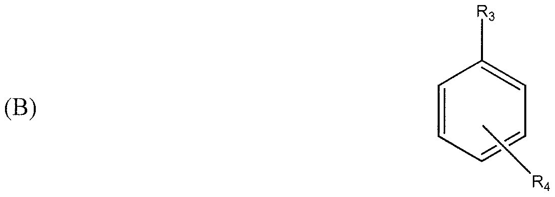
- the monomer used in formation of the high molecular weight polymer can include, but is not limited to, one or more of the monomers selected from the group consisting of:
- Rj is H or a Cl-ClO alkyl radical, more preferably Ri is H, CH 3 , or C 2 H 5 , and R 2 is H or a C1-C30 alkyl radical, more preferably R 2 is a C4-C18 alkyl radical, and is most preferably represented by formula (i) as follows
- R 5 is H or a C1-C30 alkyl radical, and preferably R 5 is a C4-C18 alkyl radical;
- R 6 is H or a C1-C30 alkyl radical, preferably R 6 is a C4-C18 alkyl radical;
- R 7 is H or a Cl-Cl 8 alkyl radical, more preferably R 7 is H or a C1-C6 alkyl radical, and R 8 is H or a Cl-Cl 8 alkyl radical, more preferably R 8 is H or a C1-C6 alkyl radical, and most preferably Rg is H or CH 3 , also, the H 2 1 S on the 1 and 4 carbons depicted above could be replaced by Cl-Cl 8 alkyl radicals or C1-C6 alkyl radicals;
- R 9 and Rj 0 are independently H, C1-C30 alkyl, aryl, cycloalkyl, or heterocyclic radicals;
- Rn and R 12 are independently H, C1-C30 alkyl, aryl, cycloalkyl, or heterocyclic radicals;
- Rn and R H are independently H, C1-C30 alkyl, aryl, cycloalkyl, or heterocyclic radicals;
- R ⁇ is H, a C1-C30 alkyl, aryl, cycloalkyl, or heterocyclic radical.
- monomers of formula (A) are preferred, especially methacrylate monomers of formula (A), and most especially 2-ethylhexyl methacrylate monomers of formula (A).
- the surfactant used in the reaction mixture can include at least one high HLB anionic or nonionic surfactant.
- HLB number refers to the hydrophile- lipophile balance of a surfactant in an emulsion. The HLB number is determined by the method described by W.C. Griffin in J. Soc. Cosmet. Chem., 1, 31 1 (1949) and J. Soc.
- high HLB shall denote an HLB number of 7 or more.
- the HLB number of surfactants for use with forming the reaction mixture can be at least about 8, about 10, or 12.
- Exemplary high HLB anionic surfactants include high HLB alkyl sulfates, alkyl ether sulfates, dialkyl sulfosuccinates, alkyl phosphates, alkyl aryl sulfonates, and sarcosinates.
- high HLB anionic surfactants include sodium lauryl sulfate (available as RHODAPON rM LSB from Rhodia Incorporated, Cranbury, NJ), dioctyl sodium sulfosuccinate (available as AEROSOLTM OT from Cytec Industries, Inc., West Paterson, NJ), 2-ethylhexyl polyphosphate sodium salt (available from Jarchem Industries Inc., Newark, NJ), sodium dodecylbenzene sulfonate (available as NORFOXTM 40 from Norman, Fox & Co., Vernon, CA), and sodium lauroylsarcosinic (available as HAMPOSYLTM L-30 from Hampshire Chemical Corp., Lexington, MA).
- sodium lauryl sulfate available as RHODAPON rM LSB from Rhodia Incorporated, Cranbury, NJ
- dioctyl sodium sulfosuccinate available as AEROSOLTM OT from Cytec Industries, Inc., West Paterson,
- Exemplary high HLB nonionic surfactants include high HLB sorbitan esters, PEG fatty acid esters, ethoxylated glycerine esters, ethoxylated fatty amines, ethoxylated sorbitan esters, block ethylene oxide/propylene oxide surfactants, alcohol/fatty acid esters, ethoxylated alcohols, ethoxylated fatty acids, alkoxylated castor oils, glycerine esters, linear alcohol ethoxylates, and alkyl phenol ethoxylates.
- nonionic surfactants include nonylphenoxy and octylphenoxy poly(ethyleneoxy) ethanols (available as the IGEP ALTM CA and CO series, respectively from Rhodia, Cranbury, NJ), C8 to Cl 8 ethoxylated primary alcohols (such as RHODASURFTM LA-9 from Rhodia Inc., Cranbury, NJ), CI l to Cl 5 secondary-alcohol ethoxylates (available as the TERGITOLTM 15-S series, including 15-S-7, 15-S-9, 15-S- 12, from Dow Chemical Company, Midland, MI), polyoxyethylene sorbitan fatty acid esters (available as the TWEEN 1 M series of surfactants from Uniquema, Wilmington, DE), polyethylene oxide (25) oleyl ether (available as SIPONICTM Y-500-70 from Americal Alcolac Chemical Co., Baltimore, MD), alkylaryl polyether alcohols (available as the TRITONTM X series, including X-IOO, X
- the initiation system for use in the reaction mixture can be any suitable system for generating free radicals necessary to facilitate emulsion polymerization.
- Possible initiators include persulfates (e.g., ammonium persulfate, sodium persulfate, potassium persulfate), peroxy persulfates, and peroxides (e.g., tert-butyl hydroperoxide) used alone or in combination with one or more reducing components and/or accelerators.
- Possible reducing components include, but are not limited to, bisulfites, metabi sulfites, ascorbic acid, erythorbic acid, and sodium formaldehyde sulfoxylate.
- Possible accelerators include, but are not limited to, any composition containing a transition metal having two oxidation states such as, for example, ferrous sulfate and ferrous ammonium sulfate.
- known thermal and radiation initiation techniques can be employed to generate the free radicals.
- the water can be a purified water such as distilled or deionized water.
- the continuous phase of the emulsion can also comprise polar organic liquids or aqueous solutions of polar organic liquids, such as those listed below.
- the reaction mixture optionally can include at least one solvent and/or a buffer.
- the at least one solvent can be an organic solvent such as a hydrocarbon solvent (e.g., pentane, hexane, heptane, benzene, toluene, xylene), a halogenated solvent (e.g., carbon tetrachloride), a glycol (e.g., ethylene glycol, propylene glycol, glycerine), an ether (e.g., diethyl ether, diglyme, polyglycols, glycol ethers).
- the solvent is a hydrocarbon solvent, such as toluene.
- the buffer can comprise any known buffer that is compatible with the initiation system such as, for example, carbonate, phosphate, and/or borate buffers.
- the monomer, water, the at least one surfactant, and optionally the at least one solvent can be combined under a substantially oxygen- free atmosphere that is maintained at less than about 1000 ppmw oxygen or less than about 100 ppmw oxygen.
- the oxygen-free atmosphere can be maintained by continuously purging the reaction vessel with an inert gas such as nitrogen and/or argon.
- the temperature of the system can kept at a level from the freezing point of the continuous phase up to about 60 0 C, or from about 0 0 C to about 45°C, or from 0 0 C to 30 0 C.
- the system pressure can be maintained in the range of from about 5 to about 100 psia, or about 10 to about 25 psia, or about atmospheric.
- a buffer can be added, if required, followed by addition of the initiation system, either all at once or over time.
- the polymerization reaction is carried out for a sufficient amount of time to achieve at least 90 percent conversion by weight of the monomers. Typically, this time period is in the range of from between about 1 to about 10 hours, or 3 to 5 hours.
- the reaction mixture can be continuously agitated.
- the emulsion polymerization reaction yields an initial latex composition comprising a dispersed phase of solid particles and a liquid continuous phase.
- the initial latex can be a stable colloidal dispersion comprising a dispersed phase of high molecular weight polymer particles and a continuous phase comprising water.
- the colloidal particles can form in the range of from about 10 to about 60 percent by weight of the initial latex, or in the range of from 40 to 50 percent by weight of the initial latex.
- the continuous phase can comprise water, the at least one high HLB surfactant, the at least one solvent (if present), and buffer as needed. Water comprises in the range of from about 20 to about 80 percent by weight of the initial latex, or about 40 to about 60 percent by weight of the initial latex.
- the high HLB surfactant comprises in the range of from about 0.1 to about 10 percent by weight of the initial latex, or from 0.25 to 6 percent by weight of the initial latex.
- the buffer is present in an amount necessary to reach the pH required for initiation of the polymerization reaction and is initiator dependent.
- the pH required to initiate a reaction is in the range of from 6.5 to 10.
- the polymer of the dispersed phase can have a weight average molecular weight (M w ) of at least about 1 x 10 6 g/mol, or at least about 2 x 10 6 g/mol, or at least 5 x 10 6 g/mol.
- the colloidal particles can have a mean particle size of less than about 10 microns, less than about 1000 nm (1 micron), in the range of from about 10 to about 500 nm, or in the range of from 50 to 250 nm. At least about 95 percent by weight of the colloidal particles can be larger than about 10 nm and smaller than about 500 nm. At least about 95 percent by weight of the particles can be larger than about 25 nm and smaller than about 250 nm.
- the polymer of the dispersed phase can exhibit little or no branching or crosslinking.
- the continuous phase can have a pH in the range of from about 4 to about 10, or from about 6 to about 8, and contains few if any multi-valent cations.
- the polymer In order for the polymer to function as a drag reducer, the polymer should dissolve or be substantially solvated in the produced fluid (e.g., crude oil and/or water).
- the produced fluid e.g., crude oil and/or water.
- the efficacy of the high molecular weight polymer particles as drag reducers when added directly to the produced fluid is largely dependent upon the temperature of the produced fluid. For example, at lower temperatures, the polymer dissolves at a lower rate in the produced fluid, therefore, less drag reduction can be achieved. However, when the temperature of the produced fluid is above about 30 0 C, or above 40 0 C, the polymer is more rapidly solvated and appreciable drag reduction is achieved.
- the initial latex can be modified to increase the dissolution rate of the polymer.
- Such modification can also provide a stable colloidal dispersion that will not significantly flocculate or agglomerate over time, thereby ensuring that the latex will not become fully broken or inverted.
- the modified latex can be formed by adding at least one low HLB surfactant and/or at least one solvent to the initial latex.
- the initial latex can be modified with both a low HLB surfactant and a solvent.
- low HLB shall denote an HLB number less than 7.
- the low HLB surfactant can have an HLB number of less than about 6, less than about 5, or in the range of from 1 to 4.
- Exemplary suitable low HLB surfactants include low HLB sorbitan esters, PEG fatty acid esters, ethoxylated glycerine esters, ethoxylated fatty amines, ethoxylated sorbitan esters, block ethylene oxide/propylene oxide surfactants, alcohol/fatty acid esters, ethoxylated alcohols, ethoxylated fatty acids, alkoxylated castor oils, glycerine esters, polyethylene glycols, linear alcohol ethoxylates, alkyl phenol ethoxylates, and oil soluble polymeric emulsifiers such as polyisobutylene succinic anhydride copolymer diethanol amine salt/amide or salt/amide mixtures, and Hypermer B-206, and mixtures thereof.
- nonanionic low HLB surfactants include sorbitan trioleate (available as SPAN T 85 from Uniqema, Wilmington, DE), sorbitan tristearate (available as SPANTM 65 from Uniqema, Wilmington, DE), sorbitan sesquioleate (available as LUMISORBTM SSO from Lambent Technologies, Skokie, IL), sorbitan monooleate (available as ALKAMULSTM SMO from Rhodia Inc., Cranbury, NJ), sorbitan monostearate (available as SPANTM 60 from Uniqema, Wilmington, DE), ethylene glycol fatty acid ester (available as MONOSTRIOLTM EN-C from Undesa, Barcelona, Spain), polyethylene glycol dioleate (such as ALKAMULSTM 600 DO from Rhodia Inc., Cranbury, NJ) propylene glycol monostearate (available as MONOSTRIOLTM PR-A from Undesa, Barcelona, Spain), glycerol monostearate (available as
- the amount of the at least one low HLB surfactant required to modify the initial latex depends on the desired dissolution rate for the polymer as well as the amount of solvent used, in order to provide the flexibility needed to adjust the dissolution rate to pipeline conditions.
- the finished formulation i.e., the modified latex drag reducer
- Suitable solvents for use in forming the modified latex drag reducer include aromatic solvents (such as benzene, toluene, xylene, ethylbenzene, dibenzyl toluene, benzyltoluene, butylxylene, diphenylethane, diisopropylbiphenyl, triisopropylbiphenyl, etc.), partially or fully hydrogenated aromatic solvents (such as tetrahydronaphthalene or decahydronaphthalene), glycols (such as ethylene glycol, propylene glycol, butylenes glycol, hexylene glycol, polyglycols such as diethylene glycol, triethylene glycol, polyethylene glycol, polypropylene glycol and ethylene oxide propylene oxide block copolymers, glycol ethers, polypropylene glycol butyl ether, ethylene glycol butyl ether, propylene glycol methyl ether, propy
- low molecular weight glycols having a molecular weight of less than about 1000, or having a molecular weight in the range of from about 100 to about 600, or in the range of from 200 to 500.
- Polyethylene glycol having a molecular weight of about 200 can also be used.
- the amount of solvent required depends on the desired dissolution rate for the polymer. The minimum amount of solvent is that which is necessary to provide the minimum desired dissolution rate in the conduit(s) carrying the treated fluid in order to maximize the amount of active drag reducing polymer.
- the modified latex drag reducer can contain in the range of from about 1 to about 95 percent by weight of the solvent, or in the range of from about 1 to about 50 percent by weight of the solvent, or in the range of from about 10 to about 30 percent by weight of the solvent, or in the range of from 15 to 25 percent by weight of the solvent.
- Modification of the initial latex can be accomplished through a simple mixing operation.
- Mixing can be accomplished using a simple overhead mixer, or the materials can be metered and proportionately fed into a continuous or static mixer depending on the viscosity of the materials selected for the modification.
- the order of addition of the modification materials has been observed to have an effect on the ease of preparation in the case of materials that have a high viscosity. In this situation, it is generally easiest to add the solvent first followed by the surfactant and lastly the latex. However, in most cases, the order of addition does not appear to have an impact on the properties of the finished mixture.
- Mixing can occur at a temperature in the of from about 5 to about 60 0 C, or in the range of from 15 to 30 0 C, under about atmospheric pressure.
- a dispersion mixer can be employed such as those used to prepare pigment dispersions.
- the time of mixing depends largely on the viscosity of the materials being used. Low viscosity mixtures can be prepared within minutes, however, mixtures of high viscosity surfactants can require extended mixing periods.
- the molecular weight of the polymer from the initial latex is substantially unaffected by the addition of the at least one modifying low HLB surfactant and the at least one solvent.
- the particle size of the colloidal particles are generally the same as in the initial latex, however, it is possible that some swelling of the particles can occur depending on the type of solvent used in the modification step. Because of this swelling, the particle size distribution can also be affected.
- the viscosity of the latex drag reducer can be increased by the addition of the surfactant and solvent.
- the maximum concentration of surfactant and solvent should be selected so that the modified latex composition remains relatively easy to pump.
- the solubility of the modified and initial latexes in a hydrocarbon-containing liquid is described herein in terms of a hydrocarbon dissolution rate constant "k.”
- the hydrocarbon dissolution rate constant (k) is determined in the manner described in Example 2, below.
- the modified latex, described above, has a hydrocarbon dissolution rate constant (k m ) that is greater than the hydrocarbon dissolution rate constant of the initial (i.e., unmodified) latex (k,).
- the hydrocarbon dissolution rate constant of the modified latex (k m ) in kerosene at 20, 40, and/or 60 0 C can be at least about 10, 25, 50, 100, or 500 percent greater than the hydrocarbon dissolution rate constant of the initial latex (k,) in kerosene at the same temperature (i.e., 20, 40, and/or 60 0 C).
- the hydrocarbon dissolution rate constant of the modified latex (k m ) in kerosene at 20 0 C can be at least about 0.004 min "1 , at least about 0.008 min "1 , or at least 0.012 min '1 .
- the hydrocarbon dissolution rate constant of the modified latex (k m ) in kerosene at 40 0 C can be at least about 0.01 min "1 , at least about 0.02 min “1 , or at least 0.04 min " '.
- the hydrocarbon dissolution rate constant of the modified latex (k m ) in kerosene at 60 0 C can be at least about 0.05 min "1 , at least about 0.2 min "1 , or at least 0.4 min “1 .
- the hydrocarbon dissolution rate constant of the initial latex (k,) in kerosene at 20 0 C can be less than about 0.004 min "1 , less than about 0.002 min "1 , or less than 0.001 min "1 .
- the hydrocarbon dissolution rate constant of the initial latex (k,) in kerosene at 40 0 C can be less than about 0.01 min "1 , less than about 0.008 min “1 , or less than 0.006 min "1 .
- the hydrocarbon dissolution rate constant of the initial latex (k,) in kerosene at 60 0 C can be less than about 0.005 min "1 , than about 0.004 min "1 , or less than 0.003 min "1 .
- the drag reducer employed in the present invention should be relatively stable so that it can be stored for long periods of time and thereafter employed as an effective drag reducer without further modification.
- shelf stability shall denote the ability of a colloidal dispersion to be stored for significant periods of time without a significant amount of the dispersed solid phase dissolving in the liquid continuous phase.
- the modified drag reducer can exhibit a shelf stability such that less than about 25, about 10, or 5 weight percent of the solid particles of high molecular weight polymer dissolves in the continuous phase over a 6-month storage period, where the modified drag reducer is stored without agitation at standard temperature and pressure (STP) during the 6- month storage period.
- dissolution rate stability shall denote the ability of a drag reducer to be stored for significant periods of time without significantly altering the hydrocarbon dissolution rate constant of the drag reducer.
- the drag reducer employed in the present invention can exhibit a dissolution rate stability such that the hydrocarbon dissolution rate constant of the drag reducer at the end of a 6-month storage period, defined above, is within about 25, about 10, or 5 percent of the hydrocarbon dissolution rate constant of the modified latex drag reducer at the beginning of the 6-month storage period.
- the drag reducers employed in the present invention can provide significant percent drag reduction.
- the drag reducers can provide at least about a 2 percent drag reduction, at least about 5 percent drag reduction, or at least 8 percent drag reduction. Percent drag reduction and the manner in which it is calculated are more fully described in Example 2, below.
- FIG. 2 there is illustrated a well 100 similar to well 20 of FIG. 1 and including an outer casing 102 and an inner production tubing 104.
- Well 100 is equipped with an alternative additive injection system 106 having a different configuration than the additive injection system of FIG. 1.
- Additive injection system 106 generally includes an additive source 108, an additive pump 110, an additive feeder conduit 1 12, and a valved sealing device 114.
- Valved sealing device 1 14 can be any device that controls fluid flow through the passageway (e.g., annulus) defined between casing 102 and tubing 104.
- valved sealing device 114 can be a conventional gas-lift valve.
- FIG. 2 illustrates only a single valved sealing device 1 14, it should be understood that well 100 can be equipped with multiple vertically-spaced valved sealing devices.
- the additive (which includes a drag reducer, as discussed above) is pumped from additive source 108 to additive feeder conduit 112 by additive pump 110.
- the outlet of additive feeder conduit 112 is in fluid communication with the passageway defined between casing 102 and packing 104.
- the additive is permitted to fall down the passageway until it reaches valved sealing device 1 14.
- the pressure in the passageway can be controlled to selectively open and close the valve of sealing device 114.
- Passageway pressure can be controlled by additive injection pump 110 or by a separate pressure control system (not shown). After the additive passes through valved sealing means 114, it can fall down into the produced fluid.
- the resulting treated fluid can thereafter be extracted and transported in the manner described above with reference to FIG. 1.
- a simplified offshore production system is illustrated as including a plurality of subsea wells 200, a common production manifold 202, an offshore platform 204, a subsea flowline 206, and an umbilical line 208.
- Each well 200 can have a configuration similar to wells 20 and 100, described above with reference to FIGS. 1 and 2.
- Each well 200 is operable to produce a hydrocarbon-containing fluid from a subterranean formation.
- the hydrocarbon-containing fluids produced by each well 200 are combined in production manifold 202 and are thereafter transported via flowline 206 to platform 204.
- a first end of umbilical line 208 is connected to a control facility on platform 204, while a second end of umbilical line 208 is connected to wells 200, manifold 202, and/or flowline 206.
- umbilical line 208 generally includes a plurality of electrical conduits 214, a plurality of fluid conduits 216, and a plurality of protective layers 218 surrounding electrical conduits 214 and fluid conduits 216.
- electrical conduits 214 carry power from platform 204 to wells 200 and/or manifold 202.
- Fluid conduits 216 commonly referred to as chemical injection lines, are typically used to inject low-viscosity flow assurance chemicals into the produced hydrocarbon-containing fluids transported back to platform 204 via flowline 206.
- Typical flow assurance chemicals which are injected through fluid conduits 216 include, but are not limited to, hydrate inhibitors, corrosion inhibitors, paraffin inhibitors, scale inhibitors, biocides, demulsifiers, hydrogen sulfide scavengers, oxygen scavengers, water treatments, and asphaltene inhibitors.
- an additive comprising a drag reducer is transported through chemical injection lines (such as fluid conduits 216) in umbilicals (such as umbilical line 208).
- the drag reducer can thereafter be employed downhole in the manner described above with respect to wells 20 and 100 of FIGS. 1 and 2.
- the "ground surface" can be the surface of the sea or the sea floor.
- the length of umbilical line 208 can be at least about 500 feet, or at least about
- each fluid conduit 216 can be about 5 inches or less, or about 2.5 inches or less, or about 1 inch or less, or about 0.5 inches or less, or about 0.25 inches or less.
- a drag reducer such as one of those described above, is transported from platform 204 to production manifold 202 via at least one of the fluid conduits 216 making up umbilical line 208. At least one fluid conduit
- the inventive drag reducers described in detail above can possess physical properties which allow them to be pumped through fluid conduit 216 of umbilical line 208 at typical operating conditions with a pressure drop of less than about 5 psi (pounds per square inch) per foot, less than about 2.5 psi per foot, or less than 1 psi per foot.
- the temperature at which the drag reducer will be transported through fluid conduit 216 is relatively low due to the cool ocean-bottom environment around umbilical line 208.
- the temperature of the drag reducer during transportation through fluid conduit 26 is generally less than about 6O 0 F, more typically less than about 40 0 F for deep sea systems.
- a drag-reducing initial latex was prepared.
- 2- ethylhexyl methacrylate was polymerized in an emulsion comprising water, surfactant, initiator, and a buffer.
- the polymerization was performed in a 300 niL jacketed reaction kettle with a condenser, mechanical stirrer, thermocouple, septum ports, and nitrogen inlets/outlets.
- the kettle was charged with 0.231 g of disodium hydro genphosphate, 0.230 g of potassium dihydrogenphosphate, and 4.473 g of sodium dodecyl sulfonate.
- the kettle was purged with nitrogen overnight.
- the kettle was charged with 125 g of deoxygenated HPLC-grade water, the kettle contents were stirred at 300 rpm, and the kettle temperature set to 5 0 C using the circulating bath.
- the 2- ethylhexyl methacrylate monomer (100 niL, 88.5 g) was then purified to remove any polymerization inhibitor present, deoxygenated (by bubbling nitrogen gas through the solution), and transferred to the kettle.
- four initiators were prepared for addition to the kettle: an ammonium persulfate (APS) solution by dissolving 0.131 g of APS in 50.0 mL of water; a sodium formaldehyde sulfoxylate (SFS) solution by dissolving 0.175 g of SFS in 100.0 mL of water; a ferrous sulfate solution by dissolving 0.021 g Of FeSO 4 ⁇ 7H 2 O in 10.0 mL water; and a tert-butyl hydroperoxide (TBHP) solution by dissolving 0.076 g of 70% TBHP in 50.0 mL of water.
- APS ammonium persulfate
- SFS sodium formaldehyde sulfoxy
- the kettle was then charged with 1.0 mL of ferrous sulfate solution and over a two-hour period, 1.0 mL of APS solution and 1.0 mL of SFS solution were added concurrently. Following APS and SFS addition, 1.0 mL of TBHP solution and 1.0 mL of SFS solution were added concurrently over a two-hour period.
- the final latex was collected after the temperature cooled back to the starting temperature.
- the final latex (216.58 g) comprised 38.3% polymer and a small amount of coagulum (0.41 g).
- Example 2 In this example, the drag reduction capabilities of the 38% poly-2-ethylhexyl methacrylate polymer emulsion prepared in Example 1 were evaluated in a #2 diesel fuel system.
- the test device used in this example was a two inch Engineering Loop Recirculation Test apparatus as shown in FIG. 5. This test allowed for the evaluation of drag reducer performance when injected in non-predissolved form into a hydrocarbon fluid in the flow loop. The test was used to simulate performance profiles and drag reducer behavior in field pipelines over a three-hour time period in terms of dissolution, peak performance, and degradation of the drag-reducing polymer.
- sample material was injected for a 2 -minute period into the pipe just downstream of the reservoir and pump, with the volume of material injected being equal to that required to obtain the target ppm for the full 600 gallon reservoir.
- Monitoring of pressure drop continued for a 3-hour period following injection.
- sufficient drag reducer polymer emulsion was injected into the test loop to yield a 5 ppm concentration of poly-2-ethylhexylmethacrylate (w/w) based on the Wl diesel fuel. No measurable drop in pressure was recorded in 3 hours of recirculation. This was equal to 0% drag reduction (% DR).
- the rate at which the polymer dissolves into the hydrocarbon stream is a very important property. The most effective drag reduction cannot occur until the polymer is dissolved or substantially solvated in the conduit.
- the rate at which the polymer dissolves can be determined by a vortex inhibition test in kerosene at various temperatures. At a constant stirring speed, the depth of the vortex is proportional to the amount of dissolved polymer in the kerosene.
- the time ,T, for a certain fraction of the polymer to be dissolved is a function of k as follows:
- FIG. 6 schematically illustrates the dissolution rate test apparatus used to determine the dissolution rate constant.
- the dissolution rate test apparatus included a rotating stirrer that was placed in a jacketed graduated 250 niL cylinder having an internal diameter of
- the rotating stirrer employed in the dissolution rate tests was a Black & Decker paint stirrer made from a casting of oil resistant plastic.
- the stirrer head was formed of a 45 mm diameter disk made up of a central disk and an outer ring.
- the central disk was 20 mm in diameter and 1.5 mm thick and was centered on a hub that was 12 mm in diameter and 12 mm thick.
- the hub was drilled in the center for attachment of the stirring head to a 4 mm diameter shaft.
- the shaft was threaded for 27 mm so that two small nuts held the stirring head to the shaft.
- the outer ring was 45 mm in diameter, 9 mm wide, and 1.5 mm thick.
- the outer ring was attached to the inner disk by 13 evenly spaced arcs 13 mm long and 1 mm thick.
- the outer disk resided 6 mm below the level of the inner disk.
- the arcs that attached the outer ring to the inner disk acted as paddles to stir the fluid in the test cylinder.
- the shaft that attached the stirring head to the stirring motor (not shown) was 300 mm long. It should be noted that dissolution rate test results can vary somewhat if different stirrer configurations are used. To conduct the dissolution rate test, the stirrer was positioned inside the cylinder and adjusted so that the bottom of stirrer head was about 5 millimeters from the bottom of the cylinder.
- the cylinder jacket was then filled with water recirculated from a recirculating water bath with controlled heating and cooling capability. The desired temperature was selected and the bath was allowed to reach that temperature.
- the jacketed graduated cylinder was filled with kerosene to the 200 niL line with the stirrer in place. The circulation of cooling fluid through the graduated cylinder jacket was initiated.
- the kerosene inside the graduated cylinder was stirred for sufficient time to allow the temperature to equilibrate at the set temperature, usually 10-15 minutes.
- the kerosene temperature was checked with a thermometer to insure that the kerosene was at the desired test temperature.
- the speed of the motor was adjusted to stir rapidly enough to form a vortex in the kerosene that reached to the 125 niL graduation in the cylinder.
- pre-dissolved polymer containing the desired concentration of polymer was added to the kerosene while the vortex was formed.
- the pre-dissolved polymer was prepared by mixing the latex emulsion with a solvent having suitable solubility parameters to achieve full dissolution.
- the container with the emulsion and solvent was rolled overnight.
- a mixture of 20% isopropanol and 80% kerosene (v/v) allowed full dissolution of the polymer at room temperature within this time period.
- a 3% solution of poly-2-ethylhexylmethacrylate was prepared by adding 7.83 grams of a 38.3% polymer emulsion into 92.17 grams of 20% isopropanol and 80% kerosene (v/v) and followed by shaking to disperse the emulsion in an 8 ounce jar. The solvent system rapidly became viscous. The jar was then placed onto a roller rotating at a slow speed and allowed to homogenize overnight.
- Emulsions which had not been pre-dissolved had their dissolution rates measured using the same polymer concentration required for full vortex closure for the pre- dissolved polymer by the following procedure.
- An aliquot of the emulsion, either modified or unmodified, was added to the kerosene at the desired concentration and temperature.
- a timer was used to monitor and record the time that the vortex reached the 130, 135, 140, 145, 150, 155, 160, 165, 170, and 175 mL marks on the cylinder. However, the determination was stopped when the time exceeded 30 minutes.
- the dissolution constant, k was calculated by first determining the relative vortex, Rv, and then plotting the time required to reach the various vortex marks vs. the log of the relative vortex.
- the relative vortex is the decimal fraction of the full vortex at
- the full vortex is the difference between 200 mL (the volume in the graduated cylinder) and the vortex at 125 mL (i.e., 75 mL).
- the relative vortex is 0.833.
- the time required to reach the various vortex marks was plotted versus the log of the relative vortex.
- a data trendline was then developed and a regression was performed on the trendline.
- the slope of the trendline was multiplied by -2.303 to convert the data back to linear values. This was the dissolution rate constant, k, for a given temperature and concentration of active polymer.
- the dissolution rate of the 38.3% poly-2-ethylhexylmethacrylate emulsion prepared in Example 1 was measured using the dissolution rate test at 500 ppm active polymer. Results show that the emulsion polymer had virtually no dissolution at 20 0 C and 30 0 C and very low dissolution rates at temperatures up to 60 0 C.
- Example 3-5 various solvents and surfactants were incorporated into the latex emulsion prepared in Example 1 in order to determine the effect thereof on the dissolution rate of the emulsion polymer in a hydrocarbon.
- Toluene (104.15 g) was added to a 600 ml beaker and the beaker placed under an overhead stirrer equipped with a 2 inch diameter 3-blade propeller. The stirrer was adjusted to 250 rpm and 41.675 grams of sorbitan sesquioleate (available as Lumisorb ®
- Example 1 SSO from Lambent Technologies, Skokie, IL was added and mixed for 10 minutes until it dissolved. A portion of the emulsion prepared in Example 1 (104.175 g) was then added and the system mixed for 20 minutes. The composition had a density of 0.939 g/ml and a Brookfield LVDVII+ viscosity of 3700 mPa-s using a # 4 spindle at 12 rpm.
- composition in terms of percent by weight was as follows: Emulsion from Example 1 41.67%
- the dissolution rate of this material was measured using the dissolution rate test described above. The results show that the modified emulsion polymer had good dissolution properties which improve with increasing temperature.
- Example 4 Toluene (104.15 g) was added to a 600 ml beaker and the beaker placed under an overhead stirrer equipped with a 2 inch diameter 3-blade propeller. The stirrer was adjusted to 250 rpm. A quantity of the emulsion prepared in Example 1 (145.85 g) was then added and the system mixed for 20 minutes. The composition had a density of 0.937 g/ml. The Brookfield LVDV1I+ viscosity was too high to be measured using this instrument at 12 rpm. The composition in terms of percent by weight was as follows:
- Sorbitan sesquioleate 0% The dissolution rate this material was measured using the dissolution rate test described above. Results show that the emulsion polymer had no dissolution at 20 0 C and 30 0 C and very low dissolution rates at temperatures up to 6O 0 C.
- Example 1 A quantity of the emulsion prepared in Example 1 (208.325 g) was added to a 600 ml beaker and the beaker placed under an overhead stirrer equipped with a 2 inch diameter 3-blade propeller. The stirrer was adjusted to 250 rpm and 41.675 g of sorbitan sesquioleate was then added and the system mixed for 20 minutes.
- the composition had a density of 0.991 g/ml and the Brookfield L VD VII+ viscosity was too high to be measured using this instrument at 12 rpm.
- the mixture had a smooth, paste-like consistency.
- the composition in terms of percent by weight is as follows:
- Examples 3, 4 and 5 illustrate the dramatic improvement in dissolution rate realized by using both a surfactant and a solvent to modify the dissolution properties of the subject emulsion polymers in hydrocarbons. Much faster dissolution can be obtained by using both a surfactant and a solvent than can be obtained by the use of either class of additive singly.
- a plot of the dissolution rate factor, k, vs. the temperature of the hydrocarbon used (kerosene) is presented in FIG. 10.
- Example 6 In this example, 75 g of acetone was added to a 600 mL beaker and the beaker placed under an overhead stirrer equipped with a 2 inch diameter 3-blade propeller. The stirrer was adjusted to 250 rpm and 50 g of sorbilan sesquioleate was added and mixed for 10 minutes until it dissolved. A quantity of the emulsion prepared in Example 1 (125 g) was then added and the system mixed for 20 minutes. The composition had a density of 0.94 g/niL and a Brookfield LVDVII+ viscosity of 6700 mPa-s using a # 4 spindle at 12 rpm. The composition in terms of percent by weight was as follows:
- Sorbitan sesquioleate 20% The dissolution rate this material was measured using the dissolution rate test described above. Results show that the modified emulsion polymer had good dissolution properties which improve with increasing temperature.
- This example illustrates how an alternate solvent can be used to achieve faster dissolution properties at a lower temperature. This can be important in many pipeline applications where the crude oil or refined products are transported at lower temperatures.
- a quantity of polyethylene glycol (96.15 g) having a molecular weight of 200 (PEG-200) was added to a 600 niL beaker and the beaker placed under an overhead stirrer equipped with a 2 inch diameter 3-blade propeller.
- the stirrer was adjusted to 250 rpm and 57.7 g of polyisobutylene succinnic anhydride copolymer dicthanolamine salt (PIBSA) was added and the system mixed for 30 minutes until the PIBSA dissolved.
- PIBSA polyisobutylene succinnic anhydride copolymer dicthanolamine salt
- the composition had a density of 0.971 g/ml and a Brookfield LVDVII+ viscosity of 32000 mPa-s using a # 4 spindle at 6 rpm.
- the composition had a thick, paste-like consistency.
- the composition in terms of percent by weight was as follows:
- the dissolution rate of this material was measured using the dissolution rate test described above. The results show that the modified emulsion polymer had good dissolution properties which improve with increasing temperature.
- Example 8 In this example, 50 g of PEG-200 was added to a 600 mL beaker and the beaker placed under an overhead stirrer equipped with a 2 inch diameter 3 -blade propeller. The stirrer was adjusted to 250 rpm and 12.5 g of an ethoxylated tallow amine (Rhodameen" PN-430) and 37.5 g of polyisobutylene succinnic anhydride copolymer, diethanolamine salt were added and mixed for 20 minutes until dissolved. Next, 150 g of the emulsion prepared in Example 1 was then added and the system mixed for 20 minutes.
- Rhodameen ethoxylated tallow amine
- the composition had a density of 1.0078 g/ml and a Brookfield LVDVII+ viscosity of 1120 niPa-s using a # 4 spindle at 30 rpm.
- the composition in terms of percent by weight was as follows: Emulsion from Example 1 60% PEG-200 20%
- the dissolution rate of this material was measured using the dissolution rate test described above. The results show that the modified emulsion polymer had good dissolution properties which improve with increasing temperature.
- This example illustrates the use of more than one low HLB surfactant to achieve an enhanced dissolution rate over the emulsion alone and allows the use of a lower concentration of solvent and low HLB surfactants to achieve a given dissolution rate at certain temperatures.
- the composition had a density of 0.9979 g/ml and a Brookfield LVDVII+ viscosity of 3071 mPa-s using a # 4 spindle at 30 rpm.
- the composition in terms of percent by weight was as follows:
- This example illustrates the use of more than one low HLB surfactant and more than one solvent to achieve an enhanced dissolution rate over the emulsion alone and allows the use of a lower concentration of solvent and low HLB surfactants to achieve a given dissolution rate at certain temperatures.
- FIG. 11 is a plot of dissolution rate vs temperature for Examples 7, 8 and 9. This comparison of the dissolution rates of the various systems illustrates that the use of more than one solvent and or low HLB surfactant can be used to achieve similar dissolution properties. In the case of Example 7, much higher additive concentrations were needed using a single surfactant and solvent to achieve only marginal improvements in dissolution rates. By using multiple surfactants and/or solvents to enable the use of a lower concentration of additives one can also achieve a mixture with a lower viscosity.
- the mixture prepared above was injected into the two inch Engineering Loop Recirculation Test apparatus described in Example 2 in a sufficient amount to yield a concentration of 3 ppm of poly-2-ethylhexylmethacrylate (w/w) based on the weight of the #2 diesel fuel. After injection, the pressure of the test loop quickly began to drop. A pressure drop equal to 10.75% DR was measured after 600 seconds (10 minutes).
- Example 1 was then added and mixed for 20 minutes.
- the composition had a density of 0.937 g/ml and the Brookfield LVDVII+ viscosity was too high to be measured using this instrument at 12 rpm.
- the composition in terms of percent by weight is as follows:
- the mixture prepared above was injected into the two inch Engineering Loop Recirculation Test apparatus as described in Example 2 in a sufficient amount to yield a concentration of 3 ppm of poly-2-ethylhexylmethacrylate (w/w) based on the weight of the #2 diesel fuel. During the 3 hour test no significant drag reduction was measured.
- Example 2 208.325 g of the emulsion prepared in Example 1 was added to a 600 mL beaker and the beaker placed under an overhead stirrer equipped with a 2 inch diameter 3-blade propeller. The stirrer was adjusted to 250 rpm and 41.675 g of sorbitan sesquioleate was then added and mixed for 20 minutes.
- the composition had a density of 0.991 g/ml and the Brookfield LVDVII+ viscosity was too high to be measured using this instrument at 12 rpm.
- the mixture had a smooth, paste-like consistency.
- the composition in terms of percent by weight was as follows:
- FIG. 12 is a plot of the drag reduction in the 2-inch Engineering Loop Recirculation Test for Examples 2, 10, 11 and 12. In this plot of % Drag reduction vs circulation time, the injection into the recirculating fluid occurred at 100 seconds.
- modified emulsions were injected at a higher concentration (21.5 ppm polymer for the modified and 35.8 ppm for the unmodified emulsion) and at a rate proportional to the flow of one pass of the diesel fuel through the loop calculated as:
- This plot illustrates the rapid rate of drag reduction of an emulsion modified with both toluene and sorbitan sesquioleate (Example 10) compared to the emulsion modified with either toluene alone (Example 1 1) or sorbitan sesquioleate alone (example 12) at an equilibrium polymer concentration of 3 ppm. Additionally the drag reduction performance of an unmodified emulsion at an equilibrium polymer concentration of 5 ppm is illustrated.
- the present description uses specific numerical values to quantify certain parameters relating to the invention, where the specific numerical values are not expressly part of a numerical range. It should be understood that each specific numerical value provided is to be construed as providing literal support for a broad, intermediate, and narrow range.
- the broad range associated with each specific numerical value is the numerical value plus and minus 60 percent of the numerical value, rounded to two significant digits.
- the intermediate range associated with each specific numerical value is the numerical value plus and minus 30 percent of the numerical value, rounded to two significant digits.
- the narrow range associated with each specific numerical value is the numerical value plus and minus 15 percent of the numerical value, rounded to two significant digits.
- drag reducer denotes a composition that when added to a host fluid is effective to reduce pressure loss associated with turbulent flow of the host fluid though a conduit.
- latex drag reducer denotes a composition containing a liquid continuous phase and a dispersed phase comprising particles of a drag reducing polymer.
- the continuous phase of the latex drag reducer can be formed at least partly of the liquid employed for emulsion polymerization or the continuous phase can be formed of a liquid entirely different from the liquid employed for emulsion polymerization.
- the continuous phase of the latex drag reducer should be a non-solvent for the dispersed phase.
- the term “average inside diameter” denotes the inside diameter of a conduit averaged along the length of the conduit.
- the terms “comprising,” “comprises,” and “comprise” are open- ended transition terms used to transition from a subject recited before the term to one or elements recited after the term, where the element or elements listed after the transition term are not necessarily the only elements that make up of the subject.
- the term "and/or,” when used in a list of two or more items, means that any one of the listed items can be employed by itself or any combination of two or more of the listed items can be employed. For example, if a composition is described as containing components A, B, and/or C, the composition can contain A alone; B alone; C alone; A and B in combination; A and C in combination; B and C in combination; or A, B, and C in combination.
Abstract
Description


Claims
Priority Applications (5)
| Application Number | Priority Date | Filing Date | Title |
|---|---|---|---|
| MX2008013492A MX2008013492A (en) | 2006-06-08 | 2007-06-04 | Downhole flow improvement. |
| BRPI0711052-9A BRPI0711052A2 (en) | 2006-06-08 | 2007-06-04 | bottom flow enhancement |
| EA200870601A EA200870601A1 (en) | 2006-06-08 | 2007-06-04 | IMPROVEMENT OF DRILLING WELLS SOLUTION |
| CA002646290A CA2646290A1 (en) | 2006-06-08 | 2007-06-04 | Downhole flow improvement |
| AU2007257979A AU2007257979A1 (en) | 2006-06-08 | 2007-06-04 | Downhole flow improvement |
Applications Claiming Priority (2)
| Application Number | Priority Date | Filing Date | Title |
|---|---|---|---|
| US11/422,922 | 2006-06-08 | ||
| US11/422,922 US20070284110A1 (en) | 2006-06-08 | 2006-06-08 | Downhole flow improvement |
Publications (2)
| Publication Number | Publication Date |
|---|---|
| WO2007146644A2 true WO2007146644A2 (en) | 2007-12-21 |
| WO2007146644A3 WO2007146644A3 (en) | 2008-10-23 |
Family
ID=38820718
Family Applications (1)
| Application Number | Title | Priority Date | Filing Date |
|---|---|---|---|
| PCT/US2007/070329 WO2007146644A2 (en) | 2006-06-08 | 2007-06-04 | Downhole flow improvement |
Country Status (7)
| Country | Link |
|---|---|
| US (1) | US20070284110A1 (en) |
| AU (1) | AU2007257979A1 (en) |
| BR (1) | BRPI0711052A2 (en) |
| CA (1) | CA2646290A1 (en) |
| EA (1) | EA200870601A1 (en) |
| MX (1) | MX2008013492A (en) |
| WO (1) | WO2007146644A2 (en) |
Families Citing this family (11)
| Publication number | Priority date | Publication date | Assignee | Title |
|---|---|---|---|---|
| CA2791492C (en) * | 2011-09-30 | 2022-08-09 | Khalil Zeidani | Hydrocarbon recovery from bituminous sands with injection of surfactant vapour |
| US9169723B2 (en) | 2012-01-25 | 2015-10-27 | Baker Hughes Incorporated | System and method for treatment of well completion equipment |
| EA201491319A1 (en) * | 2012-02-02 | 2015-02-27 | Лубризол Спешиалти Продактс, Инк. | ANTI-TURBULENT ADDITIVES ON AQUATIC BASIS FOR APPLICATION IN ARCTIC CLIMATE CONDITIONS |
| US10094201B2 (en) * | 2014-04-07 | 2018-10-09 | Abb Schweiz Ag | Chemical injection to increase production from gas wells |
| RU2018146416A (en) | 2016-06-21 | 2020-06-26 | Дау Глоубл Текнолоджиз Ллк | COMPOSITION FOR STEAM EXTRACTION OF BITUMEN |
| CN111164185B (en) | 2017-10-06 | 2022-08-23 | 陶氏环球技术有限责任公司 | Alkanolamine and glycol ether compositions for enhanced extraction of bitumen |
| CA3134708A1 (en) * | 2019-03-28 | 2020-10-01 | Championx Usa Inc. | Self-inverting polymer emulsions |
| CN111197473A (en) * | 2019-11-15 | 2020-05-26 | 王凯 | Multi-pipe polymer injection device |
| WO2022170041A1 (en) | 2021-02-04 | 2022-08-11 | Aramco Services Company | Development of ultra-high molecular weight (uhmw) branched block copolymer drag reducer with improved mechanical and chemical stability |
| US11840662B2 (en) | 2021-02-04 | 2023-12-12 | Saudi Arabian Oil Company | Development of ultra-high molecular weight (UHMW) branched block copolymer shale inhibitor for water based drilling fluid |
| US11473033B1 (en) * | 2022-01-04 | 2022-10-18 | Iris Tech, Inc. | Drag reducing agent containing a great amount of an active base |
Citations (6)
| Publication number | Priority date | Publication date | Assignee | Title |
|---|---|---|---|---|
| US3196947A (en) * | 1962-06-14 | 1965-07-27 | Marathon Oil Co | Method for facilitating the production of viscous petroleum through a well |
| US3654994A (en) * | 1970-08-06 | 1972-04-11 | Calgon Corp | Friction reducing in flowing hydrocarbon fluids |
| US3730276A (en) * | 1971-02-08 | 1973-05-01 | Cities Service Oil Co | Method of increasing productivity and the injectivity of oil wells |
| US4347899A (en) * | 1980-12-19 | 1982-09-07 | Mobil Oil Corporation | Downhold injection of well-treating chemical during production by gas lift |
| US4881566A (en) * | 1988-10-11 | 1989-11-21 | Conoco Inc. | Method for reducing pressure drop in the transportation of drag reducer |
| US20060144595A1 (en) * | 2004-12-30 | 2006-07-06 | Milligan Stuart N | Remote delivery of latex drag-reducing agent |
Family Cites Families (12)
| Publication number | Priority date | Publication date | Assignee | Title |
|---|---|---|---|---|
| US3711405A (en) * | 1969-11-19 | 1973-01-16 | Union Oil Co | Low fluid loss well treating composition and method |
| US3758406A (en) * | 1971-10-22 | 1973-09-11 | Halliburton Co | Flow of hydrocarbon liquids methods and compositions for reducing frictional pressure loss in the |
| US3748266A (en) * | 1971-11-01 | 1973-07-24 | Halliburton Co | Methods and compositions for reducing frictional pressure loss in theflow of hydrocarbon liquids |
| US3857402A (en) * | 1972-08-31 | 1974-12-31 | Nalco Chemical Co | Transmission of oil |
| FR2522359A1 (en) * | 1982-02-26 | 1983-09-02 | Petroles Cie Francaise | PROCESS AND DEVICE FOR CONVERTING A PETROLEUM WELL INTO A WINDOW OF THE EFFLUENT BY GAS LIGHTENING |
| US4635723A (en) * | 1983-07-07 | 1987-01-13 | Spivey Melvin F | Continuous injection of corrosion-inhibiting liquids |
| US4625803A (en) * | 1985-05-20 | 1986-12-02 | Shell Western E&P Inc. | Method and apparatus for injecting well treating liquid into the bottom of a reservoir interval |
| FR2621071B1 (en) * | 1987-09-29 | 1996-01-12 | Inst Francais Du Petrole | METHOD AND SYSTEM FOR PRODUCING AN EFFLUENT CONTAINED IN AN UNDERWATER GEOLOGICAL FORMATION |
| DE3807395A1 (en) * | 1988-03-07 | 1989-09-21 | Henkel Kgaa | USE OF SELECTED COPOLYMER TYPES OF ACRYLIC AND / OR METHACRYLIC ACID ESTERS AS FLOW-IMPROVERS IN PARAFFIN-LIKE PETROLEUM AND PETROLEUM FRACTIONS (II) |
| US4983186A (en) * | 1989-07-18 | 1991-01-08 | Petrolite Corporation | Methods and compositions for reduction of drag in hydrocarbon fluids |
| US5110874A (en) * | 1989-07-18 | 1992-05-05 | Petrolite Corporation | Methods and compositions for reduction of drag in hydrocarbon fluids |
| BR9705076A (en) * | 1997-10-17 | 2000-05-09 | Petroleo Brasileiro Sa | Process for the thermo-hydraulic control of gas hydrate |
-
2006
- 2006-06-08 US US11/422,922 patent/US20070284110A1/en not_active Abandoned
-
2007
- 2007-06-04 AU AU2007257979A patent/AU2007257979A1/en not_active Abandoned
- 2007-06-04 EA EA200870601A patent/EA200870601A1/en unknown
- 2007-06-04 BR BRPI0711052-9A patent/BRPI0711052A2/en not_active IP Right Cessation
- 2007-06-04 CA CA002646290A patent/CA2646290A1/en not_active Abandoned
- 2007-06-04 MX MX2008013492A patent/MX2008013492A/en not_active Application Discontinuation
- 2007-06-04 WO PCT/US2007/070329 patent/WO2007146644A2/en active Application Filing
Patent Citations (6)
| Publication number | Priority date | Publication date | Assignee | Title |
|---|---|---|---|---|
| US3196947A (en) * | 1962-06-14 | 1965-07-27 | Marathon Oil Co | Method for facilitating the production of viscous petroleum through a well |
| US3654994A (en) * | 1970-08-06 | 1972-04-11 | Calgon Corp | Friction reducing in flowing hydrocarbon fluids |
| US3730276A (en) * | 1971-02-08 | 1973-05-01 | Cities Service Oil Co | Method of increasing productivity and the injectivity of oil wells |
| US4347899A (en) * | 1980-12-19 | 1982-09-07 | Mobil Oil Corporation | Downhold injection of well-treating chemical during production by gas lift |
| US4881566A (en) * | 1988-10-11 | 1989-11-21 | Conoco Inc. | Method for reducing pressure drop in the transportation of drag reducer |
| US20060144595A1 (en) * | 2004-12-30 | 2006-07-06 | Milligan Stuart N | Remote delivery of latex drag-reducing agent |
Also Published As
| Publication number | Publication date |
|---|---|
| WO2007146644A3 (en) | 2008-10-23 |
| EA200870601A1 (en) | 2009-04-28 |
| CA2646290A1 (en) | 2007-12-21 |
| US20070284110A1 (en) | 2007-12-13 |
| AU2007257979A1 (en) | 2007-12-21 |
| MX2008013492A (en) | 2008-10-29 |
| BRPI0711052A2 (en) | 2011-08-23 |
Similar Documents
| Publication | Publication Date | Title |
|---|---|---|
| AU2005323129B2 (en) | Remote delivery of latex drag-reducing agent | |
| WO2007146644A2 (en) | Downhole flow improvement | |
| CA2586695C (en) | Modified latex drag reducer and processes therefor and therewith | |
| CA2650876C (en) | Hydrate inhibited latex flow improver | |
| US8022118B2 (en) | Drag reduction of asphaltenic crude oils | |
| EP2313682B1 (en) | Drag reducing copolymers for cold fluid applications | |
| US8124673B2 (en) | Low-viscosity drag reducer | |
| US8656950B2 (en) | Drag reduction of asphaltenic crude oils | |
| US8616236B2 (en) | Drag reduction of asphaltenic crude oils | |
| US11808112B2 (en) | Exothermic and/or gas-generating treatment for subterranean and pipeline operations |
Legal Events
| Date | Code | Title | Description |
|---|---|---|---|
| 121 | Ep: the epo has been informed by wipo that ep was designated in this application |
Ref document number: 07798073 Country of ref document: EP Kind code of ref document: A2 |
|
| WWE | Wipo information: entry into national phase |
Ref document number: 2007257979 Country of ref document: AU |
|
| WWE | Wipo information: entry into national phase |
Ref document number: 2646290 Country of ref document: CA |
|
| ENP | Entry into the national phase |
Ref document number: 2007257979 Country of ref document: AU Date of ref document: 20070604 Kind code of ref document: A |
|
| WWE | Wipo information: entry into national phase |
Ref document number: 08105188 Country of ref document: CO |
|
| WWE | Wipo information: entry into national phase |
Ref document number: MX/a/2008/013492 Country of ref document: MX |
|
| WWE | Wipo information: entry into national phase |
Ref document number: 200870601 Country of ref document: EA |
|
| NENP | Non-entry into the national phase |
Ref country code: RU |
|
| 122 | Ep: pct application non-entry in european phase |
Ref document number: 07798073 Country of ref document: EP Kind code of ref document: A2 |
|
| ENP | Entry into the national phase |
Ref document number: PI0711052 Country of ref document: BR Kind code of ref document: A2 Effective date: 20081028 |