WO2007066044A2 - Dynamic interleaving method and device - Google Patents

Dynamic interleaving method and device Download PDF

Info

Publication number
WO2007066044A2
WO2007066044A2 PCT/FR2006/051302 FR2006051302W WO2007066044A2 WO 2007066044 A2 WO2007066044 A2 WO 2007066044A2 FR 2006051302 W FR2006051302 W FR 2006051302W WO 2007066044 A2 WO2007066044 A2 WO 2007066044A2
Authority
WO
WIPO (PCT)
Prior art keywords
interleaving
symbols
law
frequency
carriers
Prior art date
Application number
PCT/FR2006/051302
Other languages
French (fr)
Other versions
WO2007066044A3 (en
Inventor
Isabelle Siaud
Anne-Marie Ulmer-Moll
Original Assignee
France Telecom
Priority date (The priority date is an assumption and is not a legal conclusion. Google has not performed a legal analysis and makes no representation as to the accuracy of the date listed.)
Filing date
Publication date
Application filed by France Telecom filed Critical France Telecom
Priority to JP2008543879A priority Critical patent/JP5209488B2/en
Priority to CN2006800519549A priority patent/CN101336534B/en
Priority to EP06842113.0A priority patent/EP1969792B1/en
Priority to KR1020087016395A priority patent/KR101324136B1/en
Priority to US12/086,237 priority patent/US8462612B2/en
Publication of WO2007066044A2 publication Critical patent/WO2007066044A2/en
Publication of WO2007066044A3 publication Critical patent/WO2007066044A3/en

Links

Classifications

    • HELECTRICITY
    • H04ELECTRIC COMMUNICATION TECHNIQUE
    • H04LTRANSMISSION OF DIGITAL INFORMATION, e.g. TELEGRAPHIC COMMUNICATION
    • H04L1/00Arrangements for detecting or preventing errors in the information received
    • H04L1/004Arrangements for detecting or preventing errors in the information received by using forward error control
    • H04L1/0056Systems characterized by the type of code used
    • H04L1/0071Use of interleaving
    • HELECTRICITY
    • H04ELECTRIC COMMUNICATION TECHNIQUE
    • H04JMULTIPLEX COMMUNICATION
    • H04J11/00Orthogonal multiplex systems, e.g. using WALSH codes
    • HELECTRICITY
    • H04ELECTRIC COMMUNICATION TECHNIQUE
    • H04LTRANSMISSION OF DIGITAL INFORMATION, e.g. TELEGRAPHIC COMMUNICATION
    • H04L1/00Arrangements for detecting or preventing errors in the information received
    • H04L1/02Arrangements for detecting or preventing errors in the information received by diversity reception
    • H04L1/04Arrangements for detecting or preventing errors in the information received by diversity reception using frequency diversity
    • HELECTRICITY
    • H04ELECTRIC COMMUNICATION TECHNIQUE
    • H04LTRANSMISSION OF DIGITAL INFORMATION, e.g. TELEGRAPHIC COMMUNICATION
    • H04L27/00Modulated-carrier systems
    • H04L27/26Systems using multi-frequency codes
    • H04L27/2601Multicarrier modulation systems
    • H04L27/2602Signal structure
    • HELECTRICITY
    • H04ELECTRIC COMMUNICATION TECHNIQUE
    • H04LTRANSMISSION OF DIGITAL INFORMATION, e.g. TELEGRAPHIC COMMUNICATION
    • H04L27/00Modulated-carrier systems
    • H04L27/26Systems using multi-frequency codes
    • H04L27/2601Multicarrier modulation systems
    • H04L27/2626Arrangements specific to the transmitter only
    • HELECTRICITY
    • H04ELECTRIC COMMUNICATION TECHNIQUE
    • H04LTRANSMISSION OF DIGITAL INFORMATION, e.g. TELEGRAPHIC COMMUNICATION
    • H04L27/00Modulated-carrier systems
    • H04L27/26Systems using multi-frequency codes
    • H04L27/2601Multicarrier modulation systems
    • H04L27/2647Arrangements specific to the receiver only
    • HELECTRICITY
    • H04ELECTRIC COMMUNICATION TECHNIQUE
    • H04LTRANSMISSION OF DIGITAL INFORMATION, e.g. TELEGRAPHIC COMMUNICATION
    • H04L5/00Arrangements affording multiple use of the transmission path
    • H04L5/02Channels characterised by the type of signal
    • H04L5/023Multiplexing of multicarrier modulation signals

Definitions

  • the present invention relates to the field of telecommunications. Within this field, the invention relates more particularly to so-called digital communications.
  • Digital communications include in particular wireless communications; they also include for example wired communications.
  • the communication transmission medium is commonly called transmission or propagation channel, originally with reference to an air channel and by extension with reference to any channel.
  • the invention relates to interleaving techniques. These techniques are generally used to reduce the correlation introduced by a selective filtering operation inherent in the transmission channel.
  • the invention applies in particular to any type of multi-carrier transmission system, for which the information put in the form of data symbols (QAM, QPSK cells, etc.) is multiplexed on a sub-network.
  • carriers corresponding to a frequency subdivision of the instantaneous band of the transmission system subjected to a frequency disturbance reflecting the effect of a transmission channel whose transfer function H (f, t) is strongly colored and little variable in time , or to a system affected by a high Doppler dispersion which generates a loss of orthogonality of the subcarriers of a multiplexing and modulation module by orthogonal functions.
  • Such a module is designated by the terms OFDM multiplex (in English “Orthogonal Frequency Division Multiplexing”) in the case of a device implementing a multiplexing of symbols modulated by subcarriers corresponding to the conjugate Fourier components of a transformation Fourier whose size N FFT corresponds to the number of sub-carriers of the OFDM multiplex.
  • OFDM multiplex in English “Orthogonal Frequency Division Multiplexing”
  • the OFDM signal useful in its temporal representation is formed by NFFT samples and results for each sample from the summation of the complex symbols modulated by the conjugated Fourier components.
  • the projection of the OFDM signal on the corresponding Fourier components and the integration on all the samples of the OFDM signal provides an estimate of one of the symbols of the OFDM multiplex.
  • a module for multiplexing and modulation by orthogonal functions of the transmitted symbols is indifferently designated by the term orthogonal multiplex in the rest of the document.
  • the transmission channel also designated by multi-path channel is represented by the impulse response h (t, t) of a digital filter where t represents the time variable and ⁇ the delay variable associated with the coefficients of the filter at time t.
  • the transmission channel filters the multicarrier signal by weighting each symbol by the channel transfer function decomposed on the OFDM multiplex.
  • the 11 generates on reception a correlation of the subcarriers in the frequency and time domains.
  • the frequency correlation affects the subcarriers and the temporal correlation induces subcarriers of almost constant amplitude over an observation window of the order of time of channel coherence.
  • the coherence time corresponds to the average value of the time difference necessary to ensure a decorrelation of the signal representative of the transmission medium with its time-shifted version.
  • the frequency correlation results from both the multi-path effect which introduces filtering, the Doppler effect and the phase noise of the RF stages which induce a loss of orthogonality of the subcarriers of an orthogonal multiplex.
  • This is in particular the case of short-range systems defined in millimeter band as studied in the American standardization body IEEE802.15.3c as well as highly mobile systems or very long distance systems dedicated to ionospheric radio links ( DRM system ("Digital World Radio") standard ETSI TS 101 980).
  • One method to remedy this double correlation consists in implementing an interleaving performed on the binary data or on the data symbols on transmission.
  • Interleaving techniques in a transmission system are therefore applied to the data to decorrelate the data received and improve the decision circuits.
  • Interleaving is said to be binary when it relates to coded bits or else to bits directly extracted from the source, bits designated by the term angiosaxon scrambling.
  • Interleaving is said to be frequency when it relates to complex symbols (QPSK, x-QAM, ...) assigned to the subcarriers of an orthogonal multiplex and its size is equal to the number of data symbols per orthogonal multiplex. Interleaving is always carried out on the useful data of the transmission device with a static interleaving law for each transmission mode defined by the number of states of the modulation, the coding, etc.
  • the useful data denotes the transmitted data carrying an information message and devoid of data dedicated to signaling and identification. In the rest of the document, the data designates the useful data.
  • the invention relates more particularly to frequency interleaving, that is to say the interleaving carried out in the frequency domain on the symbols assigned to the carriers of an orthogonal multiplex. This type of interleaving occurs at the input of an orthogonal multiplex. Equivalently, we commonly speak of interlacing of carriers or subcarriers.
  • ETSI 300 401 "Radio broadcasting Systems; Digital Audio Broadcasting (DAB) to mobile, portable and fixed receivers", May 1997, pi 82 gives a description of the frequency interleaving of the DAB multi-carrier system. It is a frequency type interleaving performed on the scale of an OFDM multiplex because the permutation law P (i) takes into account the size NFFT of the FFT of the OFDM multiplex. It is applied to system data symbols corresponding to QPSK symbols.
  • the interleaving law transforms a QPSK symbol q ⁇ jn into a new symbol yi 7 k where k is the index of the carrier after interleaving, n, the index of the carrier before interleaving and 1 the number of the OFDM symbol in the DAB frame transmitted at the time (II) TSYM, T SYM designates the total duration of the OFDM symbol accompanied by a guard interval.
  • the law of interleaving of symbols assigned to the carriers of the OFDM multiplex designated by the law of interleaving of the subcarriers is a law of the form k ⁇ Ffn) where k is the index of the data carrier in the OFDM multiplex.
  • Npm corresponds to the number of data subcarriers per OFDM multiplex.
  • the operation [X] NFFT corresponds to the modulo N FFT operation which provides the remainder of the division of X by NFFT-
  • the interleaving process of the subcarriers corresponds to the diagram in FIG. 1.
  • the latter gives the general principle of interleaving of the subcarriers in conventional systems of the OFDM type.
  • the interleaved data symbols are then framed and then distributed over the OFDM multiplex before transmission.
  • the transmission channel filters the transmitted signal which induces a correlation of the data symbols.
  • the operation of deinterleaving the data symbols upstream of the decision circuits then makes it possible to have data with a reduced correlation at the input of the decision circuit.
  • the interleaving period is generally small compared to the coherence time of the channel and error packets persist at the output of the decision circuit.
  • the technical problem to be solved by the object of the present invention is to propose a frequency interleaving method more efficient than the known methods for a transmission device comprising a multiplexing and modulation module by orthogonal functions called multiplex orthogonal, in particular an OFDM multiplex.
  • the present invention relates to a method of interleaving symbols, intended to be assigned to carriers of a multicarrier transmission device comprising a multiplexing and modulation module by N FFT orthogonal functions, consisting of interleaving a block of symbols according to a determined block interleaving law which is variable over time for a given transmission mode of the multi-carrier transmission device.
  • the subject of the invention is a frequency interleaver of symbols, intended to be assigned to carriers of a multi-carrier transmission device comprising a multiplexing and modulation module by N FFT orthogonal functions, for interleaving a block of symbols according to a determined interleaving law comprising a device for calculating the interleaving law such that the block interleaving law calculated is variable over time for a given transmission mode of the multi-carrier transmission device.
  • the invention further relates to a transmission device comprising a frequency interleaver according to the preceding object, as well as a reception device comprising a deinterlacing module performing a deinterlacing of demodulated symbols according to a law opposite to an interlacing law , the module being able to calculate at determined times the deinterlacing law, the interlacing law varying over time for a given transmission mode.
  • a method according to the invention which relates to a frequency interleaving method consisting in using a different interleaving law over time, for a given transmission mode, makes it possible to generate a fictitious temporal variability of the transmission channel which gives it statistical properties tending towards a Gaussian noise. This makes it possible to reduce the time correlation which affects a transmission system in which the data symbols are multiplexed then modulated, in particular an OFDM system, and consequently to improve the decision making on reception; the efficiency of the system is thus improved.
  • the interlacing law is dynamic.
  • the temporal variation of the interleaving law depends on a temporal index of the symbols of the orthogonal multiplex. These symbols have an index associated with the position of the carriers in the orthogonal multiplex and an index associated with the instant of emission of an orthogonal signal in a temporal pattern This signal is in the continuation of the document designated by the term modulated orthogonal symbol .
  • the interleaving law may vary after modulation of a block of N modulated orthogonal symbols, typically N OFDM symbols, N being a parameter typically determined as a function of the properties of the transmission channel and the framing of data, JV> 1 .
  • the interleaving relates to a block of M symbols and the temporal variation of the interleaving law occurs after interleaving of the block of M symbols. More particularly, M is a multiple of the number of data carriers Npm of the orthogonal multiplex, Npm ⁇ N FFT , and a sub-multiple of N. According to a particular embodiment, the temporal variation of the interleaving law occurs after interleaving of N 'blocks of M symbols.
  • An interleaving method can also, in a particularly advantageous manner, make it possible to accentuate the joint modification of the coherence band, which relates to the frequency domain of the orthogonal multiplex, the coherence band of the channel corresponding to the average value of the frequency difference necessary to ensure a decorrelation of two frequency components of the transfer function of the transmission channel, and of the coherence length, which relates to the time or space domain, of the transmission channel as well as of reduce the impact of RJF floors.
  • the method performs a dynamic block interleaving of a block composed of the data symbols intended for an orthogonal multiplex and of null symbols previously inserted at the ends of the block. This notably has the effect of introducing null symbols into the bandwidth of the orthogonal multiplex, typically OFDM orthogonal multiplex, at positions variable in time due to dynamic interleaving.
  • the dynamic interleaving for example variable in time all the N modulated orthogonal symbols, is carried out on a block of N'pm symbols constituted by non-zero data symbols and zero symbols, this block corresponding to the level of the orthogonal multiplex to N'pm subcarriers of a modulated orthogonal symbol, typically OFDM symbol.
  • N'pm is between Npm, number of data carriers and N FFT , size of the orthogonal multiplex.
  • the interleaving law is static for N modulated orthogonal symbols, typically OFDM symbols, and is applied to a block of N'pm symbols.
  • These symbols are assigned to carriers of a group formed by the data carriers of a modulated orthogonal symbol, typically OFDM, and by a portion of null carriers located at the ends of the spectrum of the modulated orthogonal symbol, typically OFDM.
  • the interleaving makes it possible to insert zero carriers in the useful band of the orthogonal multiplex, in particular of an OFDM multiplex.
  • This insertion of null carriers reinforces the effect of modifying the properties of the transmission channel obtained by P dynamic interleaving, by translating, at variable positions, these null carriers in the bandwidth of the system.
  • the total spectral efficiency of the system that is to say the ratio between the useful bit rate and the total band of the system, is not modified since the method exploits the zero carriers located at the edges of the spectrum.
  • a method according to the invention can use non-useful data, part of the null carriers of an orthogonal multiplex.
  • null carriers in the bandwidth of the system improves the decorrelation of the carriers and reduces the loss of orthogonality of the carriers in particular in the case where the transmission channel is dispersive, in particular by increasing the carrier gap between carriers. neighborhood of a null carrier in the orthogonal multiplex.
  • Such a method makes it possible to modify the properties of the transmission channel in the time and frequency domain and to jointly reduce the frequency correlation and the time correlation which affects a system, in particular of the OFDM type. This method proves to be particularly advantageous for short-range systems delivering high bit rates and in fact requiring small interleaving depths carried out upstream of the invention.
  • Ultra Wide Band systems such as the system defined by the 802.15.3a TG working group constituted by the MBOA alliance, whose references are "Physical Layer submission to 802.15 Task Group 3a: Multi-Band Orthogonal Frequency Division Multiplexing ", MBOA website, September 14, 2004, systems defined in millimeter band (broadband and ultra wideband) or systems of the Local Radio Loop type as defined in IEEE Std 802.16-2004, IEEE Standard for Local and metropolitan area networks, Part 16: Air Interface for Fixed Broadband Wireless Access Systems, October 2004.
  • the method is also relevant for systems affected by high Doppler dispersion.
  • null carriers at variable positions in time makes it possible to reduce the loss of orthogonality between carriers while ensuring a whitening of the disturbance generated by the transmission channel on the communication signal.
  • the number of null symbols added during the frequency interleaving is adjusted according to a priori knowledge of the correlation properties of the transmission channel and of the number of zero carriers conventionally added during OFDM modulation. The fact that the symbols added are zero makes it possible not to introduce additional noise.
  • the joint modification is obtained by means of an iterative interleaving algorithm applied to the null symbols and the data symbols, with an interlacing law which varies for example according to the iteration considered.
  • T algorithm uses a law of interleaving different by the number of iterations or by the parameters of interleaving, according to the constraints and global optimizations of the transmission system.
  • An interleaving law I (k) of a block of size K is a bijective function which gives the order according to which an input sequence formed by K data indexed by an index k varying from 0 to KI.
  • X (k) be an input sequence of an interleaver of interleaving law I (k).
  • Y (k) be the sequence at the output of the interleaver. So
  • Y (k) X (I (k)): the kth data of the interlaced sequence having the position index k-1 corresponds to the data of index I (kl) of the input sequence X (O) , ..., X (KI).
  • the input data to be interleaved and the interleaved output data are represented in the rest of the document only by their subscript k, unless otherwise indicated.
  • Figure 1 is a diagram illustrating an interleaving method according to the prior art.
  • Figure 2 is a diagram of a particular transmission system with interleaving according to the invention.
  • Figure 3 is a block diagram of a particular embodiment of a method according to the invention with insertion of no null symbols.
  • FIG. 4 is a block diagram of an interleaver implementing an iterative interleaving algorithm making it possible to obtain an interleaving law which is variable in time for a method according to the invention.
  • FIG. 5 is a graphic representation illustrating a particular case of optimization of an interleaving according to the invention.
  • FIG. 6 is a diagram illustrating a first example of implementation of an interleaving according to the invention in a particular OFDM transmission / reception system.
  • FIG. 7 is a diagram illustrating a second example of implementation of an interleaving according to the invention in a particular OFDM transmission / reception system.
  • FIG. 2 is a diagram of an example of a transmission system 1 implementing an interleaving method 2 according to the invention.
  • the transmission system comprises a multi-carrier transmission device 3 and a reception device 4.
  • the transmission device 3 comprises a module 5 for generating source data, a coding module 6 channel, a binary interleaving module 7, a symbol binary coding module 8, a frequency interleaver 9, a framing device 10, an OFDM modulator 11 which includes an OFDM multiplex,
  • the symbol frequency interleaver 9 in particular comprises a device for calculating the interleaving law such that the calculated block interleaving law is variable over time for a given transmission mode of the multi-carrier transmission device 3.
  • the framing device 10 distributes the data symbols and the pilot symbols in the multiplex.
  • the receiving device 4 comprises a deinterlacing module which performs a deinterlacing of demodulated symbols according to a law which is inverse to an interlacing law.
  • This deinterlacing module is able to calculate at determined times the deinterlacing law which varies over time for a given transmission mode.
  • An interleaving method 2 according to the invention is implemented by the frequency interleaver 9 of the transmission device 3. 11 applies to the SD data symbols resulting from binary symbol coding.
  • Method 2 interleaves successive SD data symbols according to a determined interleaving law.
  • the interleaving law is variable over time for a given mode of transmission.
  • the interleaved SD data symbols according to the interleaving method are assigned to one or more sets of Npm data carriers of the OFDM multiplex.
  • the OFDM multiplex includes Nf FT carriers, Npm ⁇ N FFT .
  • Figure 3 is a block diagram of a particular embodiment of a method according to the invention with insertion of no null symbols.
  • the baseband SD data symbols consisting of n coded bits converted into complex signals, are partitioned into groups of Npm contiguous symbols. no null symbols are added 12 according to an almost symmetrical distribution at the ends of each group of Npm data symbols to form a block constituted by N'pm symbols, no can typically vary between zero and a number n ⁇ x corresponding to approximately
  • Npilotes Npilotes
  • n ⁇ is set empirically.
  • each block of N'pm symbols the position of the symbols is indexed by the integer k varying from 0 to N'pm-1 and corresponds to the index of the carriers.
  • An interleaving law In (k) of size N'pm of time index n varying from 1 to NN 'where NN' corresponds to the number of different interleaving laws implemented is applied 13 to each block of N'pm symbols. This law varies in time, all the N OFDM symbols.
  • the N'pm interleaved symbols Se are put in frame 10.
  • pilot symbols are optionally added during the framing 10 and neither null symbols are inserted symmetrically at the ends of a multiplex constituted by the N'pm + Npilots branches to form an OFDM Mx multiplex with N FFT branches, N 'pm ⁇ N FFT .
  • the number of so-called zero carriers for which a null symbol is intended is therefore equal to no plus ni.
  • FIG. 4 is a block diagram of an interleaving device implementing an iterative interleaving algorithm making it possible to obtain an interleaving law which is variable in time by modifying the parameters of the interleaving or the number of iterations for a method according to the invention.
  • the interleaving device 20 implementing the algorithm comprises as many basic cells I as iterations.
  • the output of the jth basic cell Ij which corresponds to the jth iteration, provides an interlaced sequence which is expressed in the form Pj q '(£).
  • Each basic cell I of the interleaver 20 has the same structure: two inputs, one output and two elementary cells, denoted I 0 and Ii.
  • Each elementary cell Io, I 1 has two inputs and one output.
  • the two inputs of the elementary cell Io correspond to the two inputs of the basic cell I to which it belongs
  • the output of the elementary cell Ii corresponds to the output of the basic cell I to which it belongs.
  • the output of the elementary cell Io is connected to an input of the elementary cell I 1 .
  • the second input of the elementary cell U is connected to an input of the basic cell I; this input of the basic cell I being supplied by the indices k to be interleaved which generally take the form of a ramp from 0 to KI.
  • the second cell entry base 1 is connected to the output of the previous base cell 1, except for the first basic cell Ij, for which the two inputs are linked together and correspond to the index k.
  • the interleaving algorithm is thus based on an iterative structure for which the interleaving law depends on three parameters (K, p, q) and on the iteration considered j.
  • K corresponds to the size of the block to be interleaved
  • p and q are two parameters which modify the properties of the interleaving device, in particular the interlacing law and the dispersion.
  • the choice of iteration allows you to modify the interlacing law and the dispersion while keeping a pattern of size p.
  • the variation in time of the interleaving law is obtained by modifying either the iteration or one of the parameters p and q of the interleaving device.
  • This interleaving which is based on the combination of two algebraic functions Io and II with a 'turbo' structure, has the property of preserving a pattern, that is to say of preserving the order of multiplexing of p data streams after interleaving. This property proves to be very advantageous for preserving optimization operations based on a multiplexing of p data performed upstream or downstream of the interleaving operation.
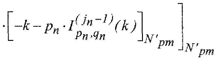
  • I o (j) (k) [-kp -I (j - !) (K) ⁇ k ⁇ ⁇ 0 KJ] ⁇ 0 ,,,,,,, K ⁇ l] (3 ⁇
  • the dispersion corresponds to the minimum distance between the position indices of the samples separated by s-1 samples of the input sequence after interleaving.
  • the dispersion is determined from a polynomial Pj, p, q, s (k):
  • This algebraic function Pj, p, q, s (k) depends on the parameters p and q of the interlacing, where p corresponds to the largest size of the preserved pattern and q is a parameter which modifies the law of interlacing, and of the iteration j considered.
  • the interlacing law varies temporally, for example all N modulated orthogonal symbols, typically N OFDM symbols, by modifying either the number of iterations or one of the parameters p and q the interleaver for a given transmission mode.
  • the parameters of the iterative interleaving algorithm are then indexed by a parameter n which is incremented every N OFDM symbols and whose maximum value corresponds to the number of different interleaving laws.
  • FIG. 5 makes it possible to illustrate an optimization of a particular embodiment of a method according to the invention.
  • the optimization of the method consists in a first step 30 of defining the number no of null symbols to be added in the frequency interleaving method to define the size N'pm of the block to be interleaved.
  • the number no is adjusted empirically as a function of the properties of the transmission channel, of the modulation considered, of the radio performance at link level and of the channeling of the system (transmission band of the signal transmitted). In practice, no is chosen at most equal to half the total number of zero carriers conventionally added to the ends of the orthogonal multiplex,
  • the invention then consists in performing a frequency interleaving of the data symbols whose size M is multiple of Npm, variable in time, for example all the N modulated orthogonal symbols, typically N OFDM symbols.
  • a second optimization step 31 consists in determining the number NN 'and the type of interlacing laws In (k) to be implemented according to the iterative algorithm described with reference to FIG. 4.
  • This algorithm generates a law of interlacing of index n less than or equal to NN ', on the one hand according to a parameter p n which preserves a pattern and modifies the dispersion, and on the other hand according to a parameter q ⁇ and an iteration j n which modify the dispersion.
  • the number NN 1 of different laws is defined as a function of the possible values for the parameter p n which is a sub-multiple of the size N'pm or M of the interleaving block according to whether one inserts null carriers or not in the block to be interleaved and the dispersion associated with the different iterations of the algorithm.
  • p n must in all cases be under multiple of the size of the interleaving block.
  • Two configurations can occur. First configuration: there is no constraint associated with a grouping of pattern conservation carriers in the OFDM multiplex. The different possible values of p ⁇ are then the sub-multiples of the size of the block to be interleaved.
  • the size of the block to be interleaved is equal to N'pm in the case of insertion of null carriers and relates to a single orthogona multiplex! or is equal to M and relates to the interleaving of data symbols assigned to several modulated orthogonal symbols.
  • the choice of p n is governed by the value of the dispersion associated with the iteration j which provides the highest dispersion between adjacent carriers and carriers separated from s-1 carriers.
  • Second configuration there is a constraint associated with a grouping of carriers to conservation of pattern size pi.
  • the value of p n chosen for the interleaving must then be a multiple of pi and preferably equal to pi.
  • the values of the parameter q n and of the iteration j n are selected to increase the interleaving dispersion between carriers separated by s-1 carriers, s is in practice less than three to ensure decorrelation between adjacent carriers .
  • the value of N is determined as a function of the properties of the channel and of the size of the block to be interleaved and of the number of interleaving laws NN ′ considered.
  • the OFDM radio transmission / reception system 40 operates in the millimeter band at 60 GHz.
  • This system implements OFDM modulation for which QPSK data symbols and 16-QAM symbols are transmitted on carrier Npm.
  • the size of the Inverse Discrete Fourier transform, TFDI is greater than Npm and allows the addition of zero carriers.
  • TFDI Inverse Discrete Fourier transform
  • the frequency interleaving method according to the invention interleave only data symbols without adding null symbols.
  • FIG. 7 corresponds, corresponding to a configuration V1
  • zero carriers are integrated in the band of the OFDM multiplex according to a frequency interleaving method according to the invention.
  • two different modes of transmission are considered:
  • a first mode defined by a transmission bandwidth greater than 500 MHz corresponding to an Ultra Wide Band (UWB according to Anglo-Saxon terminology) transmission.
  • UWB Ultra Wide Band
  • a second mode defined by a bandwidth of 200 MHz corresponding to a so-called broadband mode (WB according to Anglo-Saxon terminology).
  • OFDM parameters are determined such that the ratio x between the duration of the useful OFDM symbol T FFT and the size of the cyclic prefix Tcp is close to the value eight. Furthermore, the size of the cyclic prefix is imposed by the maximum excursion of the delays of the power profile of the propagation channel P ( ⁇ ) and is of the order of 177 ns. P ( ⁇ ) is given by:
  • ⁇ x> t represents the mean time value of the signal x according to the variable t.
  • t represents the delays.
  • An implementation of a frequency interleaving method according to the invention leads to defining a frequency interleaving size (which depends on the size of the FFT, on the number
  • Npm of data carriers and number of null carriers) for each transmission mode (UWB and WB).
  • Four frequency interleaving sizes are therefore considered for the two examples described.
  • the coded data (coded bits) are interleaved using a two-stage matrix interleaver derived from the specifications of the MBOA standard.
  • the interleaved data is formatted using a symbol binary coding operation to form data symbols in the complex domain.
  • the modulation is with constant envelope with two phase states (QPSK) with amplitude and phase modulation with 16 states,
  • the OFDM parameters are described by the number of data carriers taken into account (Npm), the size of the Fourier transform (N FFT ), the sampling frequency
  • the ratio of the number of data carriers to the number of null carriers is seven.
  • the VO configuration corresponds to an embodiment of a method according to the invention in which only dynamic interleaving of data symbols is carried out without adding a null symbol.
  • an Npm size interleaving matrix is generated to produce dynamic interleaving.
  • the law of variation of this matrix is modified at each OFDM symbol using the iterative interleaving algorithm previously described with reference to FIG. 4, two permutations Iî (k) and I2 (k) are therefore considered.
  • Table 2 in appendix 2 gives, for the WB mode, different possible values for p, for a q fixed at the value 2, for three possible iterations and for each size Npm.
  • Table 3 in appendix 2 gives different possible values for p, for a q fixed at the value
  • the configuration V1 corresponds to an embodiment of a method according to the invention in which there is insertion of null symbols and dynamic interleaving of N'pm symbols.
  • an interleaving matrix of size N'pm is generated to produce dynamic interleaving.
  • the law of variation of this matrix is modified for each OFDM symbol using the iterative interleaving algorithm described previously with reference to FIG. 4, two permutations Il (k) and I2 (k) are therefore considered.
  • Table 4 in appendix 3 gives different possible values for p, for a q fixed at the value 2, for three possible iterations and for each size N'pm, for the WB mode.
  • Table 5 in appendix 3 gives different possible values for p, for a q fixed at the value 2, for three possible iterations and for each size N'pm, for the UWB mode.
  • the parameters chosen to define the laws Il (k) and I2 (k) are those which provide the maximum dispersion.
  • the dispersion is taken into account but also the distribution of the samples.
  • two different interleaving laws can have the same dispersion.
  • the laws chosen must present a different interlacing pattern.
  • a method according to the invention can be implemented by different means.
  • the process can be implemented in wired form (hardware), in software form, or by a combination of both.
  • the frequency interleaver 9 or some of the elements of the frequency interlayer 9 used (for example the interleaver 20) to perform the different steps at the transmitter level can be integrated into one or more specific integrated circuits (ASICs), in signal processors (DSPs, DSPDs), in programmable logic circuits (PLDs, FPGAs), in controllers, microcontrollers, microprocessors, or any other electronic component designed to perform the functions previously described.
  • ASICs specific integrated circuits
  • DSPs, DSPDs signal processors
  • PLDs, FPGAs programmable logic circuits
  • controllers microcontrollers, microprocessors, or any other electronic component designed to perform the functions previously described.
  • some or all of the steps (referenced 12, 13, and for certain embodiments 30, 31, 32) of an interleaving process can be implemented by modules which execute the previously described functions.
  • the software code can be stored in memory and executed by a processor.
  • the memory can be part of the processor or be external to the processor and coupled to the latter by means known to those skilled in the art.
  • the subject of the invention is also a computer program, in particular a computer program on or in an information or memory medium, suitable for implementing the invention.
  • This program can use any programming language, and be in the form of source code, object code, or intermediate code between source code and object code such as in a partially compiled form, or in any other form desirable to implement a method according to the invention.
  • the information medium can be any entity or device capable of storing the program.
  • the support may include a storage means, such as a ROM, for example a CD ROM or a microelectronic circuit ROM, or else a magnetic recording means, for example a floppy disk or a disc. hard.
  • the information medium can be a transmissible medium such as an electrical or optical signal, which can be routed via an electrical or optical cable, by radio or by other means.
  • the program according to the invention can in particular be downloaded from a network of the Internet type. ANNEX 1
  • N p1n number of data subcarriers 280,736
  • T FFT useful life of the OFDM symbol (ns) 1406 1454
  • T SYM total duration of the OFDM symbol (ns) 1,582 1,632
  • Table 2 Possible values for the interleaving matrices for WB mode (VO configuration).

Landscapes

  • Engineering & Computer Science (AREA)
  • Signal Processing (AREA)
  • Computer Networks & Wireless Communication (AREA)
  • Detection And Prevention Of Errors In Transmission (AREA)
  • Error Detection And Correction (AREA)

Abstract

The invention relates to an interleaving method (2) and a frequency interleaver (9) for interleaving data symbols. Said data symbols are assignable to carriers of the set of NFFT carriers of the module for multiplexing and modulating by orthogonal functions of a multi-carrier transmission device (3). The inventive method consists in interleaving the block of successive Npm data symbols according to a time-varying interleaving law for a given transmission mode of the transmission device with Npm equal to or less than NFFT.

Description

PROCEDE ET DISPOSITIF D'ENTRELACEMENT DYNAMIQUE  DYNAMIC INTERLEAVING METHOD AND DEVICE
La présente invention se rapporte au domaine des télécommunications. Au sein de ce domaine, l'invention se rapporte plus particulièrement aux communications dites numériques. Les communications numériques comprennent en particulier les communications sans fil ; elles comprennent aussi par exemple les communications filaires. Le support de transmission des communications est couramment appelé canal de transmission ou de propagation, à l'origine en référence à un canal aérien et par extension en référence à tout canal. The present invention relates to the field of telecommunications. Within this field, the invention relates more particularly to so-called digital communications. Digital communications include in particular wireless communications; they also include for example wired communications. The communication transmission medium is commonly called transmission or propagation channel, originally with reference to an air channel and by extension with reference to any channel.
L'invention concerne les techniques d'entrelacement. Ces techniques sont généralement mises en œuvre pour réduire la corrélation introduite par une opération de filtrage 'sélectif inhérente au canal de transmission.  The invention relates to interleaving techniques. These techniques are generally used to reduce the correlation introduced by a selective filtering operation inherent in the transmission channel.
L'invention s'applique en particulier à tout type de système de transmission à porteuses multiples, pour lequel l'information mise sous la forme de symboles de données (cellules QAM, QPSK, ...) est multiplexée sur un réseau de sous-porteuses correspondant à une subdivision fréquentielle de la bande instantanée du système de transmission, soumis à une perturbation fréquentielle traduisant l'effet d'un canal de transmission dont la fonction de transfert H(f,t) est fortement colorée et peu variable dans le temps, ou bien à un système affecté d'une forte dispersion Doppler qui génère une perte d'orthogonalité des sous-porteuses d'un module de multiplexage et de modulation par des fonctions orthogonales. Un tel module est désigné par les termes multiplex OFDM (en anglais « Orthogonal Frequency Division Multiplexing ») dans le cas d'un dispositif mettant en œuvre un multiplexage de symboles modulés par des sous-porteuses correspondant aux composantes de Fourier conjuguées d'une transformation de Fourier dont Ia taille NFFT correspond au nombre de sous-porteuses du multiplex OFDM. A l'émission, le signal OFDM utile dans sa représentation temporelle est formé par NFFT échantillons et résulte pour chaque échantillon de la sommation des symboles complexes modulés par les composantes de Fourier conjuguées. En réception, la projection du signal OFDM sur les composantes de Fourier correspondantes et l'intégration sur l'ensemble des échantillons du signal OFDM fournit une estimation d'un des symboles du multiplex OFDM. Par analogie, un module de multiplexage et de modulation par des fonctions orthogonales des symboles transmis est indifféremment désigné par le terme multiplex orthogonal dans la suite du document. Lorsque le nombre de symboles de données par multiplex orthogonal est inférieur au nombre de fonctions orthogonales, un symbole nul est placé au centre et des symboles nuls sont placés aux extrémités du multiplex orthogonal de façon symétrique. Le canal de transmission désigné aussi par canal multitrajet est représenté par la réponse impulsionnelle h(t,t) d'un filtre numérique où t représente la variable temps et τ la variable des retards associée aux coefficients du filtre à l'instant t. Le canal de transmission filtre le signal multiporteuse en pondérant chaque symbole par la fonction de transfert du canal décomposée sur le multiplex OFDM. 11 génère en réception une corrélation des sous porteuses dans les domaines fréquentiel et temporel. La corrélation fréquentielle affecte les sous- porteuses et la corrélation temporelle induit des sous porteuses d'amplitude quasi constante sur une fenêtre d'observation de l'ordre du temps de cohérence du canal. Le temps de cohérence correspond à la valeur moyenne de l'écart temporel nécessaire pour assurer une décorrélation du signal représentatif du support de transmission avec sa version décalée temporellement. The invention applies in particular to any type of multi-carrier transmission system, for which the information put in the form of data symbols (QAM, QPSK cells, etc.) is multiplexed on a sub-network. carriers corresponding to a frequency subdivision of the instantaneous band of the transmission system, subjected to a frequency disturbance reflecting the effect of a transmission channel whose transfer function H (f, t) is strongly colored and little variable in time , or to a system affected by a high Doppler dispersion which generates a loss of orthogonality of the subcarriers of a multiplexing and modulation module by orthogonal functions. Such a module is designated by the terms OFDM multiplex (in English “Orthogonal Frequency Division Multiplexing”) in the case of a device implementing a multiplexing of symbols modulated by subcarriers corresponding to the conjugate Fourier components of a transformation Fourier whose size N FFT corresponds to the number of sub-carriers of the OFDM multiplex. On transmission, the OFDM signal useful in its temporal representation is formed by NFFT samples and results for each sample from the summation of the complex symbols modulated by the conjugated Fourier components. On reception, the projection of the OFDM signal on the corresponding Fourier components and the integration on all the samples of the OFDM signal provides an estimate of one of the symbols of the OFDM multiplex. By analogy, a module for multiplexing and modulation by orthogonal functions of the transmitted symbols is indifferently designated by the term orthogonal multiplex in the rest of the document. When the number of data symbols per orthogonal multiplex is less than the number of orthogonal functions, a null symbol is placed in the center and null symbols are placed at the ends of the orthogonal multiplex symmetrically. The transmission channel also designated by multi-path channel is represented by the impulse response h (t, t) of a digital filter where t represents the time variable and τ the delay variable associated with the coefficients of the filter at time t. The transmission channel filters the multicarrier signal by weighting each symbol by the channel transfer function decomposed on the OFDM multiplex. 11 generates on reception a correlation of the subcarriers in the frequency and time domains. The frequency correlation affects the subcarriers and the temporal correlation induces subcarriers of almost constant amplitude over an observation window of the order of time of channel coherence. The coherence time corresponds to the average value of the time difference necessary to ensure a decorrelation of the signal representative of the transmission medium with its time-shifted version.
Cette double corrélation limite les performances des circuits de décision en réception. La corrélation temporelle induit des paquets d'erreurs après décision des symboles de données transmis et après décodage des bits transmis estimés. Ces effets se rencontrent lorsque l'environnement varie lentement et est multitrajet. C'est en particulier le cas pour les systèmes ultra large bande (Ultra Wide Band), pour les systèmes radio dédiés à la boucle locale radio (Wi-max et DECT ("Digital Enhanced Cordless Télécommunications")), ou pour les transmissions de type xDSL.  This double correlation limits the performance of the receiving decision circuits. The time correlation induces error packets after decision of the transmitted data symbols and after decoding of the estimated transmitted bits. These effects are encountered when the environment varies slowly and is multi-path. This is particularly the case for ultra wide band systems (Ultra Wide Band), for radio systems dedicated to the local radio loop (Wi-max and DECT ("Digital Enhanced Cordless Telecommunications")), or for transmissions of xDSL type.
La corrélation fréquentielle résulte à la fois de l'effet multitrajet qui introduit un filtrage, de l'effet Doppler et du bruit de phase des étages RF qui induisent une perte d'orthogonalité des sous-porteuses d'un multiplex orthogonal. C'est en particulier le cas des systèmes à courte portée définis en bande millimétrique tels qu'étudiés dans l'organisme de normalisation américain IEEE802.15.3c ainsi que des systèmes à forte mobilité ou des systèmes très longue distance dédiés aux liaisons radio ionosphériques (système DRM ("Digitale Radio Mondiale") norme ETSI TS 101 980).  The frequency correlation results from both the multi-path effect which introduces filtering, the Doppler effect and the phase noise of the RF stages which induce a loss of orthogonality of the subcarriers of an orthogonal multiplex. This is in particular the case of short-range systems defined in millimeter band as studied in the American standardization body IEEE802.15.3c as well as highly mobile systems or very long distance systems dedicated to ionospheric radio links ( DRM system ("Digital World Radio") standard ETSI TS 101 980).
Une méthode pour remédier à cette double corrélation consiste à mettre en œuvre à l'émission un entrelacement effectué sur les données binaires ou sur les symboles de données.  One method to remedy this double correlation consists in implementing an interleaving performed on the binary data or on the data symbols on transmission.
Les techniques d'entrelacement dans un système de transmission sont donc appliquées sur les données pour décorréler les données reçues et améliorer les circuits de décision.  Interleaving techniques in a transmission system are therefore applied to the data to decorrelate the data received and improve the decision circuits.
Au niveau binaire lorsque Ie système est assorti d'un dispositif de redondance, ies techniques d'entrelacement appliquées après l'opération de redondance permettent de réduire la taille des paquets d'erreurs. L'entrelacement est dit binaire quand il porte sur des bits codés ou bien sur des bits directement extraits de la source, bits désignés par le terme angiosaxon scrambling.  At the binary level when the system is provided with a redundancy device, the interleaving techniques applied after the redundancy operation make it possible to reduce the size of the error packets. Interleaving is said to be binary when it relates to coded bits or else to bits directly extracted from the source, bits designated by the term angiosaxon scrambling.
L'entrelacement est dit fréquentiel quand il porte sur les symboles complexes (QPSK, x-QAM, ...) affectés aux sous-porteuses d'un multiplex orthogonal et sa taille est égale au nombre de symboles de données par multiplex orthogonal. L'entrelacement est toujours réalisé sur les données utiles du dispositif de transmission avec une loi d'entrelacement statique pour chaque mode de transmission défini par le nombre d'états de la modulation, le codage etc.. On désigne par données utiles les données transmises portant un message d'information et dépourvues de données dédiées à la signalisation et l'identification. Dans la suite du document, les données désignent les données utiles. L'invention concerne plus particulièrement les entrelacements fréquentiels, c'est-à-dire les entrelacements effectués dans le domaine fréquentiel sur les symboles affectés aux porteuses d'un multiplex orthogonal. Ce type d'entrelacement intervient en entrée d'un multiplex orthogonal. De manière équivalente, on parle couramment d'entrelacement de porteuses ou de sous-porteuses. Interleaving is said to be frequency when it relates to complex symbols (QPSK, x-QAM, ...) assigned to the subcarriers of an orthogonal multiplex and its size is equal to the number of data symbols per orthogonal multiplex. Interleaving is always carried out on the useful data of the transmission device with a static interleaving law for each transmission mode defined by the number of states of the modulation, the coding, etc. The useful data denotes the transmitted data carrying an information message and devoid of data dedicated to signaling and identification. In the rest of the document, the data designates the useful data. The invention relates more particularly to frequency interleaving, that is to say the interleaving carried out in the frequency domain on the symbols assigned to the carriers of an orthogonal multiplex. This type of interleaving occurs at the input of an orthogonal multiplex. Equivalently, we commonly speak of interlacing of carriers or subcarriers.
Le document ETSI 300 401, "Radio broadcasting Systems; Digital Audio Broadcasting (DAB) to mobile, portable and fixed receivers", May 1997, pi 82 donne une description de l'entrelacement fréquentiel du système multi porteuse DAB. Il s'agit d'un entrelacement de type fréquentiel effectué à l'échelle d'un multiplex OFDM car la loi de permutation P(i) tient compte de la taille NFFT de la FFT du multiplex OFDM. Il est appliqué sur les symboles de données du système correspondant à des symboles QPSK.  ETSI 300 401, "Radio broadcasting Systems; Digital Audio Broadcasting (DAB) to mobile, portable and fixed receivers", May 1997, pi 82 gives a description of the frequency interleaving of the DAB multi-carrier system. It is a frequency type interleaving performed on the scale of an OFDM multiplex because the permutation law P (i) takes into account the size NFFT of the FFT of the OFDM multiplex. It is applied to system data symbols corresponding to QPSK symbols.
Pour un mode de transmission donné, la loi d'entrelacement transforme un symbole QPSK qιjn en un nouveau symbole yi7k où k est l'indice de la porteuse après entrelacement, n, l'indice de la porteuse avant entrelacement et 1 le numéro du symbole OFDM dans la trame DAB transmis à l'instant (I-I)TSYM, TSYM désigne la durée totale du symbole OFDM assorti d'un intervalle de garde. La loi d'entrelacement des symboles affectés aux porteuses du multiplex OFDM désignée par loi d'entrelacement des sous-porteuses est une loi de la forme k≈Ffn) ou k est l'indice de la porteuse de données dans le multiplex OFDM. L'indice k varie entre {-Npm/2, Npm/2}\{0} et l'indice n varie entre [0, Npm-1]. Npm correspond au nombre de sous-porteuses de données par multiplex OFDM. La loi d'entrelacement est extraite d'un alphabet A qui tient compte de la taille NFFT au multiplex OFDM. En effet une loi d'entrelacement P(i) est d'abord définie pour i={0, NFFT-I } prenant les valeurs A=(P(O), P(I),For a given transmission mode, the interleaving law transforms a QPSK symbol qι jn into a new symbol yi 7 k where k is the index of the carrier after interleaving, n, the index of the carrier before interleaving and 1 the number of the OFDM symbol in the DAB frame transmitted at the time (II) TSYM, T SYM designates the total duration of the OFDM symbol accompanied by a guard interval. The law of interleaving of symbols assigned to the carriers of the OFDM multiplex designated by the law of interleaving of the subcarriers is a law of the form k≈Ffn) where k is the index of the data carrier in the OFDM multiplex. The index k varies between {-Npm / 2, Npm / 2} \ {0} and the index n varies between [0, Npm-1]. Npm corresponds to the number of data subcarriers per OFDM multiplex. The interlacing law is extracted from an alphabet A which takes account of the size N FFT at the OFDM multiplex. Indeed an interlacing law P (i) is first defined for i = {0, N FFT -I} taking the values A = (P (O), P (I),
.... P(NFFT- 1)} dans l'espace des entiers I=(O, NFFT- 1} suivant une loi P(i) de la forme : .... P (NFFT- 1)} in the space of integers I = (O, NFFT- 1} according to a law P (i) of the form:
P(O) = O  P (O) = O
P(i) {0,..NFFr -l) (1) P (i) {0, .. N FFr -l) (1)
Figure imgf000005_0001
L'opération [X]NFFT correspond à l'opération modulo NFFT qui fournit le reste de la division de X par NFFT- Les valeurs P(i) strictement inférieures à Q=(NFFτ-Npm)/2 et strictement supérieures à Npm+Q sont éliminées ainsi que la valeur NFFT/2 correspondant à la porteuse centrale. The operation [X] NFFT corresponds to the modulo N FFT operation which provides the remainder of the division of X by NFFT- The values P (i) strictly less than Q = (N FF τ-Npm) / 2 and strictly greater at Npm + Q are eliminated as well as the value N FFT / 2 corresponding to the central carrier.
Ces données sont alors réparties suivant l'ordre i croissant dans un vecteur D= (dθ, dl, ...dNpm-i} prenant ses valeurs dans l'intervalle I-{0,...., Npm-1}.  These data are then distributed according to the increasing order i in a vector D = (dθ, dl, ... dNpm-i} taking its values in the interval I- {0, ...., Npm-1}.
La correspondance F(n) =dn-NFFτ/2 est effectuée pour répartir les sous-porteuses entre les indices {— Npm/2 et Npm/2} en excluant l'indice 0 de la porteuse centrale. Le processus d'entrelacement des sous-porteuses correspond au schéma de la figure 1. Ce dernier donne le principe général d'entrelacement des sous-porteuses dans les systèmes classiques de type OFDM. Les symboles de données entrelacés sont alors mis en trame puis répartis sur le multiplex OFDM avant émission. Le canal de transmission filtre le signal émis ce qui induit une corrélation des symboles de données. En réception, l'opération de désentrelacemenl des symboles de données en amont des circuits de décision permet alors de disposer de données avec une corrélation réduite à l'entrée du circuit de décision. Toutefois, pour les systèmes correspondants, la période d'entrelacement est en général petite devant le temps de cohérence du canal et des paquets d'erreur persistent en sortie du circuit de décision. The correspondence F (n) = dn-N F Fτ / 2 is carried out to distribute the subcarriers between the indices {- Npm / 2 and Npm / 2} by excluding the index 0 from the central carrier. The interleaving process of the subcarriers corresponds to the diagram in FIG. 1. The latter gives the general principle of interleaving of the subcarriers in conventional systems of the OFDM type. The interleaved data symbols are then framed and then distributed over the OFDM multiplex before transmission. The transmission channel filters the transmitted signal which induces a correlation of the data symbols. On reception, the operation of deinterleaving the data symbols upstream of the decision circuits then makes it possible to have data with a reduced correlation at the input of the decision circuit. However, for the corresponding systems, the interleaving period is generally small compared to the coherence time of the channel and error packets persist at the output of the decision circuit.
Aussi, le problème technique à résoudre par l'objet de la présente invention est de proposer un procédé d'entrelacement fréquentiel plus efficace que les procédés connus pour un dispositif d'émission comprenant un module de multiplexage et de modulation par des fonctions orthogonales dit multiplex orthogonal, en particulier un multiplex OFDM.  Also, the technical problem to be solved by the object of the present invention is to propose a frequency interleaving method more efficient than the known methods for a transmission device comprising a multiplexing and modulation module by orthogonal functions called multiplex orthogonal, in particular an OFDM multiplex.
A cette fin, la présente invention a pour objet un procédé d'entrelacement de symboles, destinés à être affectés à des porteuses d'un dispositif d'émission multi porteuses comprenant un module de multiplexage et de modulation par NFFT fonctions orthogonales, consistant à entrelacer un bloc de symboles suivant une loi d'entrelacement bloc déterminée variable dans le temps pour un mode de transmission donné du dispositif d'émission multi porteuses. To this end, the present invention relates to a method of interleaving symbols, intended to be assigned to carriers of a multicarrier transmission device comprising a multiplexing and modulation module by N FFT orthogonal functions, consisting of interleaving a block of symbols according to a determined block interleaving law which is variable over time for a given transmission mode of the multi-carrier transmission device.
En outre, l'invention a pour objet un entrelaceur fréquentiel de symboles, destinés à être affectés à des porteuses d'un dispositif d'émission multi porteuses comprenant un module de multiplexage et de modulation par NFFT fonctions orthogonales, pour entrelacer un bloc de symboles suivant une loi d'entrelacement déterminée comprenant un dispositif de calcui de la loi d'entrelacement tel que Ia loi d'entrelacement bloc calculée est variable dans le temps pour un mode de transmission donné du dispositif d'émission multi porteuses. Furthermore, the subject of the invention is a frequency interleaver of symbols, intended to be assigned to carriers of a multi-carrier transmission device comprising a multiplexing and modulation module by N FFT orthogonal functions, for interleaving a block of symbols according to a determined interleaving law comprising a device for calculating the interleaving law such that the block interleaving law calculated is variable over time for a given transmission mode of the multi-carrier transmission device.
L'invention en outre pour objet un dispositif d'émission comprenant un entrelaceur fréquentiel selon l'objet précédent, ainsi qu'un dispositif de réception comprenant un module de desentrelacement effectuant un desentrelacement de symboles démodulés selon une loi inverse à une loi d'entrelacement, le module étant apte à calculer à des instants déterminés la loi de desentrelacement, la loi d'entrelacement variant avec le temps pour un mode de transmission donné.  The invention further relates to a transmission device comprising a frequency interleaver according to the preceding object, as well as a reception device comprising a deinterlacing module performing a deinterlacing of demodulated symbols according to a law opposite to an interlacing law , the module being able to calculate at determined times the deinterlacing law, the interlacing law varying over time for a given transmission mode.
Ainsi, un procédé selon l'invention, qui concerne un procédé d'entrelacement fréquentiel consistant à utiliser une loi d'entrelacement différente au cours du temps, pour un mode de transmission donné, permet de générer une variabilité temporelle fictive du canal de transmission qui lui confère des propriétés statistiques tendant vers un bruit gaussien. Ceci permet de réduire la corrélation temporelle qui affecte un système de transmission dans lequel les symboles de données sont multiplexes puis modulés, en particulier un système OFDM, et par conséquent d'améliorer la prise de décision en réception ; l'efficacité du système est ainsi améliorée. Contrairement aux procédés connus pour lesquels la loi d'entrelacement est statique pour un mode de transmission donné, la loi d'entrelacement est dynamique. Selon un mode de réalisation particulier, la variation temporelle de Ia loi d'entrelacement dépend d'un indice temporel des symboles du multiplex orthogonal. Ces symboles possèdent un indice associé à la position des porteuses dans le multiplex orthogonal et un indice associé à l'instant d'émission d'un signal orthogonal dans un motif temporel Ce signal est dans la suite du document désigné par le terme symbole orthogonal modulé. En particulier, la loi d'entrelacement peut varier après modulation d'un bloc de N symboles orthogonaux modulés, typiquement N symboles OFDM, N étant un paramètre déterminé typiquement en fonction des propriétés du canal de transmission et du tramage des données, JV > 1 . Selon un autre mode de réalisation particulier, l'entrelacement porte sur un bloc de M symboles et la variation temporelle de la loi d'entrelacement intervient après entrelacement du bloc de M symboles. Plus particulièrement, M est un multiple du nombre de porteuses de données Npm du multiplex orthogonal, Npm≤NFFT , et un sous-multiple de N. Selon un mode de réalisation particulier, la variation temporelle de la loi d'entrelacement intervient après entrelacement de N' blocs de M symboles. Thus, a method according to the invention, which relates to a frequency interleaving method consisting in using a different interleaving law over time, for a given transmission mode, makes it possible to generate a fictitious temporal variability of the transmission channel which gives it statistical properties tending towards a Gaussian noise. This makes it possible to reduce the time correlation which affects a transmission system in which the data symbols are multiplexed then modulated, in particular an OFDM system, and consequently to improve the decision making on reception; the efficiency of the system is thus improved. Unlike known methods for which the interlacing law is static for a given transmission mode, the interlacing law is dynamic. According to a particular embodiment, the temporal variation of the interleaving law depends on a temporal index of the symbols of the orthogonal multiplex. These symbols have an index associated with the position of the carriers in the orthogonal multiplex and an index associated with the instant of emission of an orthogonal signal in a temporal pattern This signal is in the continuation of the document designated by the term modulated orthogonal symbol . In particular, the interleaving law may vary after modulation of a block of N modulated orthogonal symbols, typically N OFDM symbols, N being a parameter typically determined as a function of the properties of the transmission channel and the framing of data, JV> 1 . According to another particular embodiment, the interleaving relates to a block of M symbols and the temporal variation of the interleaving law occurs after interleaving of the block of M symbols. More particularly, M is a multiple of the number of data carriers Npm of the orthogonal multiplex, Npm≤N FFT , and a sub-multiple of N. According to a particular embodiment, the temporal variation of the interleaving law occurs after interleaving of N 'blocks of M symbols.
Un procédé d'entrelacement selon l'invention peut, en outre, de manière particulièrement avantageuse, permettre d'accentuer la modification conjointe de la bande de cohérence, qui se rapporte au domaine fréquentiel du multiplex orthogonal, la bande de cohérence du canal correspondant à la valeur moyenne de l'écart fréquentiel nécessaire pour assurer une décorrélation de deux composantes fréquentielles de la fonction de transfert du canal de transmission, et de la longueur de cohérence, qui se rapporte au domaine temporel ou spatial, du canal de transmission ainsi que de réduire l'impact des étages RJF. A cette fin en particulier, le procédé effectue un entrelacement bloc dynamique d'un bloc composé des symboles de données destinés à un multiplex orthogonal et de symboles nuls préalablement insérés aux extrémités du bloc. Ceci a notamment pour effet d'introduire des symboles nuls dans la bande passante du multiplex orthogonal, multiplex orthogonal typiquement OFDM, à des positions variables dans le temps du fait de l'entrelacement dynamique.  An interleaving method according to the invention can also, in a particularly advantageous manner, make it possible to accentuate the joint modification of the coherence band, which relates to the frequency domain of the orthogonal multiplex, the coherence band of the channel corresponding to the average value of the frequency difference necessary to ensure a decorrelation of two frequency components of the transfer function of the transmission channel, and of the coherence length, which relates to the time or space domain, of the transmission channel as well as of reduce the impact of RJF floors. To this end in particular, the method performs a dynamic block interleaving of a block composed of the data symbols intended for an orthogonal multiplex and of null symbols previously inserted at the ends of the block. This notably has the effect of introducing null symbols into the bandwidth of the orthogonal multiplex, typically OFDM orthogonal multiplex, at positions variable in time due to dynamic interleaving.
L'entrelacement dynamique, par exemple variable dans le temps tous les N symboles orthogonaux modulés, est effectué sur un bloc de N'pm symboles constitué par des symboles de données non nuls et des symboles nuls, ce bloc correspondant au niveau du multiplex orthogonal à N'pm sous-porteuses d'un symbole orthogonal modulé, symbole typiquement OFDM. N'pm est compris entre Npm, nombre de porteuses de données et NFFT, taille du multiplex orthogonal. Typiquement, la loi d'entrelacement est statique pour N symboles orthogonaux modulés, symboles typiquement OFDM, et est appliquée sur un bloc de N'pm symboles. Ces symboles sont affectés à des porteuses d'un groupe formé par les porteuses de données d'un symbole orthogonal modulé, typiquement OFDM, et par une portion de porteuses nulles localisées aux extrémités du spectre du symbole orthogonal modulé, typiquement OFDM. Ainsi, l'entrelacement permet d'insérer des porteuses nulles dans la bande utile du multiplex orthogonal, en particulier d'un multiplex OFDM. Cette insertion de porteuses nulles renforce l'effet de modification des propriétés du canal de transmission obtenu par P entrelacement dynamique, en translatant, à des positions variables, ces porteuses nulles dans la bande passante du système. L'efficacité spectrale totale du système, c'est-à-dire le rapport entre le débit utile et la bande totale du système, n'est pas modifiée puisque le procédé exploite les porteuses nulles localisées aux bords du spectre. Ainsi, contrairement aux dispositifs d'entrelacement connus, qui compte tenu de leur faible efficacité vis-à-vis des variations Doppler sont de fait appliqués sur tes données utiles à transmettre et non sur des données dédiées à la signalisation, à l'estimation du canal de transmission ou à ia synchronisation, un procédé selon l'invention peut exploiter des données non utiles, une partie des porteuses nulles d'un multiplex orthogonal. The dynamic interleaving, for example variable in time all the N modulated orthogonal symbols, is carried out on a block of N'pm symbols constituted by non-zero data symbols and zero symbols, this block corresponding to the level of the orthogonal multiplex to N'pm subcarriers of a modulated orthogonal symbol, typically OFDM symbol. N'pm is between Npm, number of data carriers and N FFT , size of the orthogonal multiplex. Typically, the interleaving law is static for N modulated orthogonal symbols, typically OFDM symbols, and is applied to a block of N'pm symbols. These symbols are assigned to carriers of a group formed by the data carriers of a modulated orthogonal symbol, typically OFDM, and by a portion of null carriers located at the ends of the spectrum of the modulated orthogonal symbol, typically OFDM. Thus, the interleaving makes it possible to insert zero carriers in the useful band of the orthogonal multiplex, in particular of an OFDM multiplex. This insertion of null carriers reinforces the effect of modifying the properties of the transmission channel obtained by P dynamic interleaving, by translating, at variable positions, these null carriers in the bandwidth of the system. The total spectral efficiency of the system, that is to say the ratio between the useful bit rate and the total band of the system, is not modified since the method exploits the zero carriers located at the edges of the spectrum. Thus, unlike known interleaving devices, which, given their low efficiency with respect to Doppler variations, are in fact applied to your useful data to transmit and not to data dedicated to signaling, to the estimation of the transmission or synchronization channel, a method according to the invention can use non-useful data, part of the null carriers of an orthogonal multiplex.
L'intégration de porteuses nulles dans la bande passante du système améliore la décorrelation des porteuses et réduit la perte d'orthogonalité des porteuses en particulier dans le cas où le canal de transmission est dispersif, en particulier en accroissant l'écart interporteuse des porteuses au voisinage d'une porteuse nulle dans le multiplex orthogonal. Un tel procédé permet de modifier les propriétés du canal de transmission dans le domaine temporel et fréquentiel et de réduire conjointement la corrélation fréquentielle et la corrélation temporelle qui affecte un système, en particulier de type OFDM. Ce procédé s'avère particulièrement intéressant pour des systèmes à courte portée délivrant des débits élevés et nécessitant de fait des profondeurs d'entrelacement faibles effectués en amont de l'invention. C'est le cas des systèmes Ultra Large Bande, tels que le système défini par le groupe de travail 802.15.3a TG constitué par l'alliance MBOA, dont les références sont "Physical Layer Submission to 802.15 Task Group 3a : Multi-Band Orthogonal Frequency Division Multiplexing", MBOA website, September 14, 2004, des systèmes définis en bande millimétrique (large bande et ultra large bande) ou bien des systèmes de type Boucle Locale Radio comme défini dans la norme IEEE Std 802.16-2004, IEEE Standard for Local and metropolitan area networks, Part 16: Air Interface for Fixed Broadband Wireless Access Systems, October 2004. Le procédé s'avère en outre pertinent pour des systèmes affectés d'une forte dispersion Doppler. L'introduction de porteuses nulles à des positions variables dans le temps permet de réduire la perte d'orthogonalité entre porteuses tout en assurant un blanchiement de la perturbation générée par le canal de transmission sur le signal de communication. Typiquement, le nombre de symboles nuls ajoutés lors de l'entrelacement fréquentiel est ajusté suivant une connaissance à priori des propriétés de corrélation du canal de transmission et du nombre de porteuses nulles classiquement ajoutées lors d'une modulation OFDM. Le fait que les symboles ajoutés soient nuls permet de ne pas introduire de bruit supplémentaire. The integration of null carriers in the bandwidth of the system improves the decorrelation of the carriers and reduces the loss of orthogonality of the carriers in particular in the case where the transmission channel is dispersive, in particular by increasing the carrier gap between carriers. neighborhood of a null carrier in the orthogonal multiplex. Such a method makes it possible to modify the properties of the transmission channel in the time and frequency domain and to jointly reduce the frequency correlation and the time correlation which affects a system, in particular of the OFDM type. This method proves to be particularly advantageous for short-range systems delivering high bit rates and in fact requiring small interleaving depths carried out upstream of the invention. This is the case for Ultra Wide Band systems, such as the system defined by the 802.15.3a TG working group constituted by the MBOA alliance, whose references are "Physical Layer Submission to 802.15 Task Group 3a: Multi-Band Orthogonal Frequency Division Multiplexing ", MBOA website, September 14, 2004, systems defined in millimeter band (broadband and ultra wideband) or systems of the Local Radio Loop type as defined in IEEE Std 802.16-2004, IEEE Standard for Local and metropolitan area networks, Part 16: Air Interface for Fixed Broadband Wireless Access Systems, October 2004. The method is also relevant for systems affected by high Doppler dispersion. The introduction of null carriers at variable positions in time makes it possible to reduce the loss of orthogonality between carriers while ensuring a whitening of the disturbance generated by the transmission channel on the communication signal. Typically, the number of null symbols added during the frequency interleaving is adjusted according to a priori knowledge of the correlation properties of the transmission channel and of the number of zero carriers conventionally added during OFDM modulation. The fact that the symbols added are zero makes it possible not to introduce additional noise.
Selon un mode particulier de réalisation, la modification conjointe est obtenue au moyen d'un algorithme d'entrelacement itératif appliqué sur les symboles nuls et les symboles de données, avec une loi d'entrelacement qui varie par exemple suivant l'itération considérée. According to a particular embodiment, the joint modification is obtained by means of an iterative interleaving algorithm applied to the null symbols and the data symbols, with an interlacing law which varies for example according to the iteration considered.
Cet algorithme a fait l'objet d'une demande de brevet français N° FRO 04 141 13.This algorithm was the subject of a French patent application N ° FRO 04 141 13.
Typiquement, après N symboles orthogonaux modulés, T algorithme utilise une loi d'entrelacement différente par le nombre d'itérations ou par les paramètres de l'entrelacement, suivant les contraintes et optimisations globales du système de transmission. Typically, after N modulated orthogonal symbols, T algorithm uses a law of interleaving different by the number of iterations or by the parameters of interleaving, according to the constraints and global optimizations of the transmission system.
Une loi d'entrelacement I(k) d'un bloc de taille K est une fonction bijective qui donne l'ordre suivant lequel doit être lue, en sortie, une séquence d'entrée formée par K données indicées par un indice k variant de 0 à K-I. Soit X(k) une séquence en entrée d'un entrelaceur de loi d'entrelacement I(k). Soit Y(k) la séquence en sortie de l'entrelaceur. Alors An interleaving law I (k) of a block of size K is a bijective function which gives the order according to which an input sequence formed by K data indexed by an index k varying from 0 to KI. Let X (k) be an input sequence of an interleaver of interleaving law I (k). Let Y (k) be the sequence at the output of the interleaver. So
Y(k) = X(I(k)) : la kième donnée de la séquence entrelacée ayant l'indice de position k-1 correspond à la donnée d'indice I(k-l) de la séquence d'entrée X(O),..., X(K-I). Les données d'entrée à entrelacer et les données entrelacées de sortie sont représentées dans la suite du document uniquement par leur indice k, sauf indication contraire. Y (k) = X (I (k)): the kth data of the interlaced sequence having the position index k-1 corresponds to the data of index I (kl) of the input sequence X (O) , ..., X (KI). The input data to be interleaved and the interleaved output data are represented in the rest of the document only by their subscript k, unless otherwise indicated.
D'autres caractéristiques et avantages de l'invention apparaîtront lors de la description qui suit faite en regard de figures annexées données à titre d'exemples non limitatifs.  Other characteristics and advantages of the invention will become apparent from the following description given with reference to the appended figures given by way of nonlimiting examples.
La figure 1 est un schéma illustrant un procédé d'entrelacement selon l'art antérieur. Figure 1 is a diagram illustrating an interleaving method according to the prior art.
La figure 2 est un schéma d'un système de transmission particulier avec un entrelacement selon l'invention. Figure 2 is a diagram of a particular transmission system with interleaving according to the invention.
La figure 3 est un schéma de principe d'un mode particulier de réalisation d'un procédé selon l'invention avec insertion de no symboles nuls.  Figure 3 is a block diagram of a particular embodiment of a method according to the invention with insertion of no null symbols.
La figure 4 est un schéma de principe d'un entrelaceur mettant en œuvre un algorithme d'entrelacement itératif permettant d'obtenir une loi d'entrelacement variable dans le temps pour un procédé selon l'invention.  FIG. 4 is a block diagram of an interleaver implementing an iterative interleaving algorithm making it possible to obtain an interleaving law which is variable in time for a method according to the invention.
La figure 5 est une représentation graphique illustrant un cas particulier d'optimisation d'un entrelacement selon l'invention.  FIG. 5 is a graphic representation illustrating a particular case of optimization of an interleaving according to the invention.
La figure 6 est un schéma illustrant un premier exemple de mise en œuvre d'un entrelacement selon l'invention dans un système particulier d'émission/réception OFDM.  FIG. 6 is a diagram illustrating a first example of implementation of an interleaving according to the invention in a particular OFDM transmission / reception system.
La figure 7 est un schéma illustrant un deuxième exemple de mise en œuvre d'un entrelacement selon l'invention dans un système particulier d'émission/réception OFDM.  FIG. 7 is a diagram illustrating a second example of implementation of an interleaving according to the invention in a particular OFDM transmission / reception system.
La figure 2 est un schéma d'un exemple d'un système 1 de transmission mettant en œuvre un procédé 2 d'entrelacement selon l'invention. Le système de transmission comprend un dispositif 3 d'émission multi porteuses et un dispositif 4 de réception. Le dispositif 3 d'émission comprend un module 5 de génération de données sources, un module 6 de codage canal, un module 7 d'entrelacement binaire, un module 8 de codage binaire à symbole, un entrelaceur 9 fréquentiel, un dispositif de mise en trame 10, un modulateur OFDM 1 1 qui comprend un multiplex OFDM, FIG. 2 is a diagram of an example of a transmission system 1 implementing an interleaving method 2 according to the invention. The transmission system comprises a multi-carrier transmission device 3 and a reception device 4. The transmission device 3 comprises a module 5 for generating source data, a coding module 6 channel, a binary interleaving module 7, a symbol binary coding module 8, a frequency interleaver 9, a framing device 10, an OFDM modulator 11 which includes an OFDM multiplex,
L' entrelaceur 9 fréquentiel de symboles comprend en particulier un dispositif de calcul de la loi d'entrelacement tel que la loi d'entrelacement bloc calculée est variable dans le temps pour un mode de transmission donné du dispositif 3 d'émission multi porteuses. Le dispositif de mise en trame 10 répartit les symboles de données et les symboles pilotes dans le multiplex.  The symbol frequency interleaver 9 in particular comprises a device for calculating the interleaving law such that the calculated block interleaving law is variable over time for a given transmission mode of the multi-carrier transmission device 3. The framing device 10 distributes the data symbols and the pilot symbols in the multiplex.
Le dispositif 4 de réception comprend un module de desentrelacement qui effectue un desentrelacement de symboles démodulés selon une loi inverse à une loi d'entrelacement. Ce module de desentrelacement est apte à calculer à des instants déterminés la loi de desentrelacement qui varie avec le temps pour un mode de transmission donné.  The receiving device 4 comprises a deinterlacing module which performs a deinterlacing of demodulated symbols according to a law which is inverse to an interlacing law. This deinterlacing module is able to calculate at determined times the deinterlacing law which varies over time for a given transmission mode.
Un procédé 2 d'entrelacement selon l'invention est mis en œuvre par l' entrelaceur 9 fréquentiel du dispositif 3 d'émission. 11 s'applique sur les symboles de données SD issus du codage binaire à symbole.  An interleaving method 2 according to the invention is implemented by the frequency interleaver 9 of the transmission device 3. 11 applies to the SD data symbols resulting from binary symbol coding.
Le procédé 2 entrelace des symboles de données SD successifs suivant une loi d'entrelacement déterminée. Selon l'invention, la loi d'entrelacement est variable dans le temps pour un mode de transmission donné. Les symboles de données SD entrelacés selon le procédé d'entrelacement sont affectés à un ou plusieurs ensembles de Npm porteuses de données du multiplex OFDM.  Method 2 interleaves successive SD data symbols according to a determined interleaving law. According to the invention, the interleaving law is variable over time for a given mode of transmission. The interleaved SD data symbols according to the interleaving method are assigned to one or more sets of Npm data carriers of the OFDM multiplex.
Le multiplex OFDM comprend Nf FT porteuses, Npm≤ NFFT . The OFDM multiplex includes Nf FT carriers, Npm≤ N FFT .
La figure 3 est un schéma de principe d'un mode particulier de réalisation d'un procédé selon l'invention avec insertion de no symboles nuls.  Figure 3 is a block diagram of a particular embodiment of a method according to the invention with insertion of no null symbols.
Les symboles de données SD en bande de base, constitués par n bits codés convertis sous la forme de signaux complexes sont partitionnés en groupes de Npm symboles contigus. no symboles nuls sont ajoutés 12 suivant une répartition quasi symétrique aux extrémités de chaque groupe de Npm symboles de données pour former un bloc constitué par N'pm symboles, no peut varier typiquement entre zéro et un nombre n^x correspondant à environThe baseband SD data symbols, consisting of n coded bits converted into complex signals, are partitioned into groups of Npm contiguous symbols. no null symbols are added 12 according to an almost symmetrical distribution at the ends of each group of Npm data symbols to form a block constituted by N'pm symbols, no can typically vary between zero and a number n ^ x corresponding to approximately
10% du nombre Npm de symboles de données ou correspondant typiquement à (NFFT-Npm-10% of the number Npm of data symbols or typically corresponding to (NFFT-Npm-
Npilotes)/2 où Npilotes correspond au nombre de symboles pilotes par multiplex OFDM dédiés à l'estimation de canal, à un dispositif de synchronisation ou de signalisation. Cette limite n^ est fixée empiriquement. Npilotes) / 2 where Npilotes corresponds to the number of pilot symbols per OFDM multiplex dedicated to channel estimation, to a synchronization or signaling device. This limit n ^ is set empirically.
Dans chaque bloc de N'pm symboles, la position des symboles est indicée par l'entier k variant de 0 à N'pm-1 et correspond à l'indice des porteuses. Une loi d'entrelacement In(k) de taille N'pm d'indice temporel n variant de 1 à NN' où NN' correspond au nombre de lois d'entrelacement différentes mises en œuvre est appliquée 13 sur chaque bloc de N'pm symboles. Cette loi varie temporellement, tous les N symboles OFDM. Les N'pm symboles Se entrelacés sont mis en trame 10. Conformément à la génération classique d'un signal OFDM en temps, réalisée au moyen d'une transformée de Foυrier inverse de taille NFFT, des symboles pilotes sont optionnellement ajoutés lors de la mise en trame 10 et ni symboles nuls sont insérés 15 de façon symétrique aux extrémités d'un multiplex constitué par les N'pm+ Npilotes branches pour former un multiplex OFDM Mx à NFFT branches, N' pm < NFFT . In each block of N'pm symbols, the position of the symbols is indexed by the integer k varying from 0 to N'pm-1 and corresponds to the index of the carriers. An interleaving law In (k) of size N'pm of time index n varying from 1 to NN 'where NN' corresponds to the number of different interleaving laws implemented is applied 13 to each block of N'pm symbols. This law varies in time, all the N OFDM symbols. The N'pm interleaved symbols Se are put in frame 10. In accordance with the conventional generation of an OFDM signal in time, carried out by means of an inverse Foυrier transform of size N FFT , pilot symbols are optionally added during the framing 10 and neither null symbols are inserted symmetrically at the ends of a multiplex constituted by the N'pm + Npilots branches to form an OFDM Mx multiplex with N FFT branches, N 'pm <N FFT .
Chaque porteuses fk d'indice k du multiplex OFDM Mx module un symbole de la branche k à l'aide de la composante de Fourier :  Each carrier fk of index k of the OFDM multiplex Mx modulates a symbol of the branch k using the Fourier component:
NFFT hlFFT N FFT hl FFT
où k varie de 0 à NFFT-1, SOUS réserve que les échantillons soient alternativement multipliés par (-l)m en sortie de la transformée de Fourier inverse, et où m correspond à l'indice de l'échantillon en sortie du multiplex OFDM Mx. where k varies from 0 to N F FT-1, PROVIDED that the samples are alternately multiplied by (-l) m at the output of the inverse Fourier transform, and where m corresponds to the index of the sample at the output of the OFDM Mx multiplex.
Le nombre ni de symboles nuls ajoutés 15 aux extrémités du multiplex Mx après mise en trame 10 dépend de la taille NFFT de la Transformée de Fourier Directe Inverse, TFDI, de la taille d'un groupe de symboles de données, Npm, du nombre de symboles nuls no ajoutés 12 pour former un bloc de taille N'pm symboles et du nombre de symboles pilotes Npilotes ajoutés lors de la mise en trame 10, nl= NFFT - N'pm-Npilotes - NFFT -(Npm+no)-Npilotes. Le nombre de porteuses dites nulles auxquelles sont destinées un symbole nul est donc égal à no plus ni . The number ni of null symbols added 15 to the ends of the multiplex Mx after framing 10 depends on the size NFFT of the Reverse Direct Fourier Transform, TFDI, on the size of a group of data symbols, Npm, on the number of null symbols no added 12 to form a block of size N'pm symbols and of the number of pilot symbols Npilotes added during the framing 10, nl = N FFT - N'pm-Npilotes - N FFT - (Npm + no) - Pilots. The number of so-called zero carriers for which a null symbol is intended is therefore equal to no plus ni.
La figure 4 est un schéma de principe d'un dispositif d'entrelacement mettant en œuvre un algorithme d'entrelacement itératif permettant d'obtenir une loi d'entrelacement variable dans le temps en modifiant les paramètres de l'entrelacement ou le nombre d'itérations pour un procédé selon l'invention.  FIG. 4 is a block diagram of an interleaving device implementing an iterative interleaving algorithm making it possible to obtain an interleaving law which is variable in time by modifying the parameters of the interleaving or the number of iterations for a method according to the invention.
Le dispositif 20 d'entrelacement mettant en œuvre l'algorithme comprend autant de cellules de base I que d'itérations. La sortie de la jième cellule Ij de base, qui correspond à la jième itération, fournit une séquence entrelacée qui s'exprime sous la forme Pjq' (£) . La mise en œuvre de l'algorithme permet d'effectuer un entrelacement bloc de taille K à J itérations d'indice j, J étant supérieur ou égal à 1, de données numériques d'entrée indicées par une variable k = {0,....,K -l} . The interleaving device 20 implementing the algorithm comprises as many basic cells I as iterations. The output of the jth basic cell Ij, which corresponds to the jth iteration, provides an interlaced sequence which is expressed in the form Pj q '(£). The implementation of the algorithm makes it possible to perform a block interleaving of size K with J iterations of index j, J being greater than or equal to 1, of digital input data indexed by a variable k = {0 ,. ..., K -l}.
Chaque cellule de base I du dispositif 20 d'entrelacement présente la même structure : deux entrées, une sortie et deux cellules élémentaires, notées I0 et Ii . Chaque cellule élémentaire Io , I1, comporte deux entrées et une sortie. Les deux entrées de la cellule élémentaire Io correspondent aux deux entrées de la cellule de base I à laquelle elle appartient, la sortie de la cellule élémentaire Ii correspond à la sortie de la cellule de base I à laquelle elle appartient. La sortie de la cellule élémentaire Io est reliée à une entrée de la cellule élémentaire I1. La seconde entrée de la cellule élémentaire U est reliée à une entrée de la cellule de base I ; cette entrée de la cellule de base I étant alimentée par les indices k à entrelacer qui se présentent généralement sous la forme d'une rampe de 0 à K-I. La seconde entrée de la cellule de base 1 est reliée à la sortie de la cellule de base 1 précédente, sauf pour la première cellule Ij de base, pour laquelle les deux entrées sont reliées entre elles et correspondent à l'indice k. Each basic cell I of the interleaver 20 has the same structure: two inputs, one output and two elementary cells, denoted I 0 and Ii. Each elementary cell Io, I 1 , has two inputs and one output. The two inputs of the elementary cell Io correspond to the two inputs of the basic cell I to which it belongs, the output of the elementary cell Ii corresponds to the output of the basic cell I to which it belongs. The output of the elementary cell Io is connected to an input of the elementary cell I 1 . The second input of the elementary cell U is connected to an input of the basic cell I; this input of the basic cell I being supplied by the indices k to be interleaved which generally take the form of a ramp from 0 to KI. The second cell entry base 1 is connected to the output of the previous base cell 1, except for the first basic cell Ij, for which the two inputs are linked together and correspond to the index k.
L'algorithme d'entrelacement repose ainsi sur une structure itérative pour laquelle la loi d'entrelacement dépend de trois paramètres (K, p, q) et de l'itération considérée j. K correspond à la taille du bloc à entrelacer, p et q sont deux paramètres qui modifient les propriétés du dispositif d'entrelacement, notamment la loi d'entrelacement et la dispersion. Le choix de l'itération permet de modifier la loi d'entrelacement et la dispersion tout en conservant un motif de taille p. La variation dans le temps de la loi d'entrelacement est obtenue en modifiant soit l'itération, soit un des paramètres p et q du dispositif d'entrelacement.  The interleaving algorithm is thus based on an iterative structure for which the interleaving law depends on three parameters (K, p, q) and on the iteration considered j. K corresponds to the size of the block to be interleaved, p and q are two parameters which modify the properties of the interleaving device, in particular the interlacing law and the dispersion. The choice of iteration allows you to modify the interlacing law and the dispersion while keeping a pattern of size p. The variation in time of the interleaving law is obtained by modifying either the iteration or one of the parameters p and q of the interleaving device.
Cet entrelacement qui repose sur la combinaison de deux fonctions algébriques Io et II à structure 'turbo', a la propriété de préserver un motif, c'est-à-dire de conserver l'ordre de multiplexage de p flux de données après entrelacement. Cette propriété s'avère très intéressante pour préserver des opérations d'optimisation reposant sur un multiplexage de p données réalisées en amont ou en aval de l'opération d'entrelacement.  This interleaving, which is based on the combination of two algebraic functions Io and II with a 'turbo' structure, has the property of preserving a pattern, that is to say of preserving the order of multiplexing of p data streams after interleaving. This property proves to be very advantageous for preserving optimization operations based on a multiplexing of p data performed upstream or downstream of the interleaving operation.
La loi d'entrelacement /„ q J^(k) correspondant aux paramètres p et q et l'itération j, résulte de la combinaison de deux fonctions algébriques à deux entrées et une sortie. Pour l'itération j=l, un motif de taille p et un paramètre q, cette loi s'exprime par les équations : The interlacing law / „ q J ^ (k) corresponding to the parameters p and q and the iteration j, results from the combination of two algebraic functions with two inputs and one output. For the iteration j = l, a pattern of size p and a parameter q, this law is expressed by the equations:
W*.*0 = [-* - V /O, * = {o,....,* -i} W *. * 0 = [- * - V / O, * = {o , .... , * - i }
kP,AkA) - [κ - P + k + q . P - ^ k = [O ,κ -i} k P, A k A) - [κ - P + k + q . P - ^ k = [O, κ -i}
IM{k,kï) = 1, (k, Io(k, kïj) I M {k, kï) = 1, (k, Io (k, kïj)
et le bloc d'équations (2) :  and the block of equations (2):
Ip,q(k) = [κ -p + k + q .p-I°Ptq(k)] k = {0,....,K -l}
Figure imgf000012_0001
I p, q (k) = [κ -p + k + q .pI ° Ptq (k)] k = {0, ...., K -l}
Figure imgf000012_0001
IPιq(k) = [K-p + k + q - p -[-k-p -k)]κ]κ k = {0, K ~ l] I Pιq (k) = [Kp + k + q - p - [- kp -k)] κ ] κ k = {0, K ~ l]
Pour l'itération j, le bloc d'équations (2) est de la forme :  For iteration j, the block of equations (2) is of the form:
Io (j)(k) = [-k-p -I(j-!)(k)^ k ^ {0 K-J] {0,,,,,,K~l] (3}
Figure imgf000012_0002
I o (j) (k) = [-kp -I (j - !) (K) ^ k ^ {0 KJ] {0 ,,,,,, K ~ l] (3}
Figure imgf000012_0002
I<J)(k) k = {0.....,K - l]I < J) (k) k = {0 ....., K - l]
Figure imgf000012_0003
La séquence des données de sortie entrelacées Y(k) est reϋée à la séquence des données d'entrée avant entrelacement X(k) par la relation : The sequence of interleaved output data Y (k) is given to the sequence of input data before interleaving X (k) by the relation:
Ya) = X(Ip J^k)) . La structure pseudo périodique et algébrique de l'algorithme permet de pré-calculer la dispersion Min Ip (J q ) (k + s) - Pfq ] (k)\ entre bits ou échantillons séparés par s- 1 échantillons. Ya) = X (I p J ^ k)). The pseudo periodic and algebraic structure of the algorithm makes it possible to pre-calculate the dispersion Min I p (J q ) (k + s) - Pf q ] (k) \ between bits or samples separated by s- 1 samples.
La dispersion correspond à la distance minimale entre les indices de position des échantillons séparés par s-î échantillons de la séquence d'entrée après entrelacement.  The dispersion corresponds to the minimum distance between the position indices of the samples separated by s-1 samples of the input sequence after interleaving.
La dispersion
Figure imgf000013_0001
est déterminée à partir d'un polynôme Pj,p,q,s(k) :
The dispersion
Figure imgf000013_0001
is determined from a polynomial Pj, p, q, s (k):
Pj.p.qJ*) = Ip JJ(k + s)~Ip (JJ(k) = s-[q.p-(s + p - Pj_IιS(k))]κ
Figure imgf000013_0002
P j . p . q J *) = I p J J (k + s) ~ I p (J J (k) = s- [q . p- (s + p - P j _ IιS (k))] κ
Figure imgf000013_0002
Figure imgf000013_0003
- Mi«A j|s -[q - p(s + p p -(s + p• Pj,p,q,s(k))]κ
Figure imgf000013_0003
- Mi “ A j | s - [q - p (s + pp - (s + p • P j, p, q, s (k))] κ
Figure imgf000013_0004
Cette fonction algébrique Pj,p,q,s(k) dépend des paramètres p et q de l'entrelacement, où p correspond à la plus grande taille du motif préservé et q est un paramètre qui modifie la loi d'entrelacement, et de l'itération j considérée. This algebraic function Pj, p, q, s (k) depends on the parameters p and q of the interlacing, where p corresponds to the largest size of the preserved pattern and q is a parameter which modifies the law of interlacing, and of the iteration j considered.
Selon un mode particulier de réalisation, un procédé selon l'invention comprend un tel algorithme d'entrelacement itératif et un entrelaceur 9 fréquentiel selon l'invention comprend un tel dispositif 20 d'entrelacement, avec une taille K correspondant au nombre de symboles par symbole orthogonal modulé, typiquement symbole OFDM, donc K= N'pm, La loi d'entrelacement varie temporellement, par exemple tous les N symboles orthogonaux modulés, typiquement N symboles OFDM, en modifiant soit le nombre d'itérations, soit un des paramètres p et q du dispositif d'entrelacement pour un mode de transmission donné. Les paramètres de l'algorithme d'entrelacement itératif sont alors indicés par un paramètre n qui est incrémenté tous les N symboles OFDM et dont la valeur maximale correspond au nombre de lois d'entrelacement différentes.  According to a particular embodiment, a method according to the invention comprises such an iterative interleaving algorithm and a frequency interleaver 9 according to the invention comprises such an interleaving device 20, with a size K corresponding to the number of symbols per symbol orthogonal modulated, typically OFDM symbol, therefore K = N'pm, The interlacing law varies temporally, for example all N modulated orthogonal symbols, typically N OFDM symbols, by modifying either the number of iterations or one of the parameters p and q the interleaver for a given transmission mode. The parameters of the iterative interleaving algorithm are then indexed by a parameter n which is incremented every N OFDM symbols and whose maximum value corresponds to the number of different interleaving laws.
La loi d'entrelacement donnée par les blocs d'équations (2) et (3) est modifiée pour prendre en compte le caractère dynamique de cette loi comme suit : pu, qn et jn sont les paramètres choisis pour la loi m(k) et NN' correspond au nombre de lois considérées.The interlacing law given by the blocks of equations (2) and (3) is modified to take into account the dynamic nature of this law as follows: p u , q n and j n are the parameters chosen for the law m (k) and NN 'corresponds to the number of laws considered.
Figure imgf000013_0005
Pn Mn ' y N'pm-pn +k + qn .pn (5)Pn Mn 'y N' pm -p n + k + qn .p n (5)
Figure imgf000013_0006
k = {θ ,N1 Pn- I) k = {θ, N 1 Pn - I)
La relation entre l'indice n, indiquant une variation de la loi d'entrelacement et l'indice m associé à l'émission du symbole modulé, typiquement symbole OFDM, à l'instant ΠITSYM dépend du nombre N de symboles modulés typiquement OFDM, pour lequel la loi d'entrelacement est inchangée:
Figure imgf000014_0001
The relationship between the index n, indicating a variation of the interlacing law and the index m associated with the emission of the modulated symbol, typically OFDM symbol, at the instant ΠIT SYM depends on the number N of typically OFDM modulated symbols , for which the interlacing law is unchanged:
Figure imgf000014_0001
où E{x} désigne la partie entière de x. where E {x} denotes the integer part of x.
L'exemple suivant auquel correspond la figure 5 permet d'illustrer une optimisation d'un mode particulier de réalisation d'un procédé selon l'invention.  The following example to which FIG. 5 corresponds makes it possible to illustrate an optimization of a particular embodiment of a method according to the invention.
L'optimisation du procédé consiste dans une première étape 30 à définir le nombre no de symboles nuls à ajouter dans le procédé d'entrelacement fréquentiel pour définir la taille N'pm du bloc à entrelacer. Le nombre no est ajusté empiriquement en fonction des propriétés du canal de transmission, de la modulation considérée, des performances radio au niveau lien et de la canalisation du système (bande de transmission du signal émis). En pratique, no est choisi au plus égal à la moitié du nombre total de porteuses nulles classiquement ajoutées aux extrémités du multiplex orthogonal,  The optimization of the method consists in a first step 30 of defining the number no of null symbols to be added in the frequency interleaving method to define the size N'pm of the block to be interleaved. The number no is adjusted empirically as a function of the properties of the transmission channel, of the modulation considered, of the radio performance at link level and of the channeling of the system (transmission band of the signal transmitted). In practice, no is chosen at most equal to half the total number of zero carriers conventionally added to the ends of the orthogonal multiplex,
no≤ (NFFT - Npm - Npilotes)! 2, N' pm - Npm + no . no≤ (N FFT - Npm - Npilotes)! 2, N 'pm - Npm + no.
Si le système comporte un nombre trop restreint de porteuses nulles classiquement ajoutées aux extrémités du multiplex orthogonal ou bien n'en dispose pas, alors aucun symbole nul n'est ajouté lors de l'entrelacement fréquentiel et N'pm=Npm. L'invention consiste alors à effectuer un entrelacement fréquentiel des symboles de données dont la taille M est multiple de Npm, variable dans le temps, par exemple tous les N symboles orthogonaux modulés, typiquement N symboles OFDM.  If the system includes too small a number of null carriers conventionally added to the ends of the orthogonal multiplex or else does not have one, then no null symbol is added during the frequency interleaving and N'pm = Npm. The invention then consists in performing a frequency interleaving of the data symbols whose size M is multiple of Npm, variable in time, for example all the N modulated orthogonal symbols, typically N OFDM symbols.
Une deuxième étape 31 d'optimisation consiste à déterminer le nombre NN' et le type de lois d'entrelacement In(k) à mettre en œuvre suivant l'algorithme itératif décrit en regard de la figure 4. Cet algorithme génère une loi d'entrelacement d'indice n inférieur ou égal à NN', d'une part suivant un paramètre pn qui préserve un motif et modifie la dispersion, et d'autre part suivant un paramètre qα et une itération jn qui modifient la dispersion. Le nombre NN1 de lois différentes est défini en fonction des valeurs possibles pour le paramètre pn qui est un sous-multiple de la taille N'pm ou M du bloc d'entrelacement selon que l'on insère des porteuses nulles ou pas dans le bloc à entrelacer et de la dispersion associée aux différentes itérations de l'algorithme. pn doit être dans tous les cas sous multiple de la taille du bloc d'entrelacement Deux configurations peuvent se présenter. Première configuration : il n'existe aucune contrainte associée à un regroupement de porteuses à conservation de motif dans le multiplex OFDM, Les différentes valeurs possibles de pπ sont alors les sous-multiples de la taille du bloc à entrelacer. La taille du bloc à entrelacer est égal à N'pm dans le cas d'insertion de porteuses nulles et se rapporte à un seul multiplex orthogona! ou bien est égal à M et se rapporte à l'entrelacement de symboles de données affectés à plusieurs symboles orthogonaux modulés. Le choix de pn est régi par la valeur de la dispersion associée à l'itération j qui fournit la dispersion la plus élevée entre porteuses adjacentes et porteuses séparées de s-1 porteuses. Seconde configuration : il existe une contrainte associée à un regroupement de porteuses à conservation de motif de taille pi. La valeur de pn choisie pour l'entrelacement doit alors être multiple de pi et préférentiellement égale à pi . Pour cette seconde configuration, les valeurs du paramètre qn et de l'itération jn sont sélectionnées pour augmenter la dispersion d'entrelacement entre porteuses séparées par s-1 porteuses, s est en pratique inférieur à trois pour assurer une décorrélation entre porteuses adjacentes. A second optimization step 31 consists in determining the number NN 'and the type of interlacing laws In (k) to be implemented according to the iterative algorithm described with reference to FIG. 4. This algorithm generates a law of interlacing of index n less than or equal to NN ', on the one hand according to a parameter p n which preserves a pattern and modifies the dispersion, and on the other hand according to a parameter q α and an iteration j n which modify the dispersion. The number NN 1 of different laws is defined as a function of the possible values for the parameter p n which is a sub-multiple of the size N'pm or M of the interleaving block according to whether one inserts null carriers or not in the block to be interleaved and the dispersion associated with the different iterations of the algorithm. p n must in all cases be under multiple of the size of the interleaving block. Two configurations can occur. First configuration: there is no constraint associated with a grouping of pattern conservation carriers in the OFDM multiplex. The different possible values of p π are then the sub-multiples of the size of the block to be interleaved. The size of the block to be interleaved is equal to N'pm in the case of insertion of null carriers and relates to a single orthogona multiplex! or is equal to M and relates to the interleaving of data symbols assigned to several modulated orthogonal symbols. The choice of p n is governed by the value of the dispersion associated with the iteration j which provides the highest dispersion between adjacent carriers and carriers separated from s-1 carriers. Second configuration: there is a constraint associated with a grouping of carriers to conservation of pattern size pi. The value of p n chosen for the interleaving must then be a multiple of pi and preferably equal to pi. For this second configuration, the values of the parameter q n and of the iteration j n are selected to increase the interleaving dispersion between carriers separated by s-1 carriers, s is in practice less than three to ensure decorrelation between adjacent carriers .
Lors d'une troisième étape 32, la valeur de N est déterminée en fonction des propriétés du canal et de la taille du bloc à entrelacer et du nombre de lois d'entrelacement NN' considéré.  During a third step 32, the value of N is determined as a function of the properties of the channel and of the size of the block to be interleaved and of the number of interleaving laws NN ′ considered.
Un exemple de mise en œuvre d'un entrelacement selon l'invention est décrit ci-après en regard des schémas de la figure 6 et de la figure 7 d'un système d'émissïon/réception OFDM mettant en œuvre un tel procédé.  An example of implementation of an interleaving according to the invention is described below with reference to the diagrams in FIG. 6 and in FIG. 7 of an OFDM transmission / reception system implementing such a method.
Le système 40 radio d'émission/réception OFDM fonctionne en bande millimétrique à 60 GHz. Ce système met en œuvre une modulation OFDM pour laquelle des symboles de données QPSK et des symboles 16-QAM sont transmis sur Npm porteuses. La taille de la transformée de Fourier Discrète Inverse, TFDI, est supérieure à Npm et permet l'ajout de porteuses nulles. Selon un premier exemple décrit, auquel correspond la figure 6, correspondant à une configuration VO, aucune porteuse nulle n'est intégrée dans la bande du multiplex OFDM et la taille de la FFT est inchangée, le procédé d'entrelacement fréquentiel selon l'invention entrelace uniquement des symboles de données sans ajout de symboles nuls. Selon un second exemple décrit, auquel correspond la figure 7, correspondant à une configuration Vl, des porteuses nulles sont intégrées dans la bande du multiplex OFDM selon un procédé d'entrelacement fréquentiel selon l'invention. Pour chacun des deux exemples, deux modes de transmission différents sont considérés :  The OFDM radio transmission / reception system 40 operates in the millimeter band at 60 GHz. This system implements OFDM modulation for which QPSK data symbols and 16-QAM symbols are transmitted on carrier Npm. The size of the Inverse Discrete Fourier transform, TFDI, is greater than Npm and allows the addition of zero carriers. According to a first example described, to which corresponds FIG. 6, corresponding to a VO configuration, no null carrier is integrated in the band of the OFDM multiplex and the size of the FFT is unchanged, the frequency interleaving method according to the invention interleave only data symbols without adding null symbols. According to a second example described, to which FIG. 7 corresponds, corresponding to a configuration V1, zero carriers are integrated in the band of the OFDM multiplex according to a frequency interleaving method according to the invention. For each of the two examples, two different modes of transmission are considered:
Un premier mode défini par une largeur de bande de transmission supérieure à 500 MHz correspondant à une transmission Ultra Large Bande (UWB selon une terminologie anglo-saxonne).  A first mode defined by a transmission bandwidth greater than 500 MHz corresponding to an Ultra Wide Band (UWB according to Anglo-Saxon terminology) transmission.
Un second mode défini par une largeur de bande de 200 MHz correspondant à un mode dit large bande (WB selon une terminologie anglo-saxonne).  A second mode defined by a bandwidth of 200 MHz corresponding to a so-called broadband mode (WB according to Anglo-Saxon terminology).
Pour ces deux bandes de transmission, des paramètres OFDM sont déterminés tels que le rapport x entre la durée du symbole OFDM utile TFFT et la taille du préfixe cyclique Tcp soit proche de la valeur huit. Par ailleurs, la taille du préfixe cyclique est imposée par l'excursion maximale des retards du profil de puissance du canal de propagation P(τ) et est de l'ordre de 177 ns. P(τ) est donné par : For these two transmission bands, OFDM parameters are determined such that the ratio x between the duration of the useful OFDM symbol T FFT and the size of the cyclic prefix Tcp is close to the value eight. Furthermore, the size of the cyclic prefix is imposed by the maximum excursion of the delays of the power profile of the propagation channel P (τ) and is of the order of 177 ns. P (τ) is given by:
P(T)≈<
Figure imgf000015_0001
∑ < ai n >n• δ(τ- < τi n >n ) (7) <x>t représente la valeur moyenne temporelle du signal x suivant la variable t. t représente les retards. Après échantillonnage discret de la réponse impulsiormelle h(t,τ) du canal, Ia variable n est affectée à la variable t et la variable i aux retards τi.
P (T) ≈ <
Figure imgf000015_0001
Σ <a in> n • δ (τ- <τ in> n) (7) <x> t represents the mean time value of the signal x according to the variable t. t represents the delays. After discrete sampling of the impulse response h (t, τ) of the channel, the variable n is assigned to the variable t and the variable i to the delays τi.
Ceci impose donc un écart inter-porteuse ΔFFl quasi identique pour ces deux modes de transmission (ΔFFT=TFFT~!=(X Tcp)"1). Seul le nombre de porteuses de données est modifié en fonction de la taille de la bande. This therefore imposes an almost identical inter-carrier difference Δ FFl for these two modes of transmission (ΔFFT = TFFT ~! = (X Tcp) "1 ). Only the number of data carriers is modified according to the size of the band .
Une mise en œuvre d'un procédé d'entrelacement fréquentiel selon l'invention conduit à définir une taille d'entrelacement fréquentiel (qui dépend de la taille de la FFT, du nombre An implementation of a frequency interleaving method according to the invention leads to defining a frequency interleaving size (which depends on the size of the FFT, on the number
Npm de porteuses de données et du nombre no de porteuses nulles) pour chaque mode (UWB et WB) de transmission. Quatre tailles d'entrelacement fréquentiels sont donc considérées pour les deux exemples décrits. Npm of data carriers and number of null carriers) for each transmission mode (UWB and WB). Four frequency interleaving sizes are therefore considered for the two examples described.
Les bits utiles issus de la source sont encodés à l'aide d'un code convolutif de rendement 1/3 et de longueur de contrainte M-7 à l'aide des polynômes générateurs {gθ, gl, g2}- {133O, 145O, 1710) . Ce code est poinçonné pour donner lieu à un rendement de code r=5/8. Les données codées (bits codés) sont entrelacées à l'aide d'un entrelaceur matriciel à deux étages dérivés des spécifications de la norme MBOA. Les données entrelacées sont mises en forme à l'aide d'une opération de codage binaire à symbole pour former des symboles de données dans le domaine complexe. La modulation est à enveloppe constante à deux états de phase (QPSK) avec une modulation d'amplitude et de phase à 16 états, The useful bits from the source are encoded using a convolutional code of 1/3 efficiency and of constraint length M-7 using the generator polynomials {gθ, gl, g2} - {133 O , 145 O , 171 0 ). This code is punched to give rise to a return of code r = 5/8. The coded data (coded bits) are interleaved using a two-stage matrix interleaver derived from the specifications of the MBOA standard. The interleaved data is formatted using a symbol binary coding operation to form data symbols in the complex domain. The modulation is with constant envelope with two phase states (QPSK) with amplitude and phase modulation with 16 states,
Ces symboles sont ensuite entrelacés suivant un procédé d'entrelacement fréquentiel selon l'invention.  These symbols are then interleaved according to a frequency interleaving method according to the invention.
Les paramètres OFDM sont décrits par le nombre de porteuses de données prises en compte (Npm), la taille de la transformée de Fourier (NFFT), la fréquence d'échantillonnageThe OFDM parameters are described by the number of data carriers taken into account (Npm), the size of the Fourier transform (N FFT ), the sampling frequency
(Fe) et la durée de l'intervalle de garde ou préfixe cyclique Tcp. Ces quatre paramètres permettent de déterminer la durée utile du symbole OFDM (TFFT), la durée totale du symbole(Fe) and the duration of the guard interval or cyclic prefix Tcp. These four parameters are used to determine the useful life of the OFDM symbol (T FFT ), the total duration of the symbol
OFDM Ts YM avec le préfixe cyclique, l'écart interporteuse ΔFIrr , le débit, etc... ιFFT E OFDM Ts YM with the cyclic prefix, the inter-carrier deviation Δ FI rr, the flow rate, etc ... ι FFT E
- , Δp— - -, Δp— -
NFFT TFFT N FFT T FFT
TSYM = TFFT + τCp = (χ + DTCP TSYM = TFFT + τ C p = ( χ + DT CP
Du = mR - Npm = mR - Npm -(l - ro) (âébit) Du = mR - Npm = mR - Npm - (l - ro) (flow)
TSYM (X + O- TCP  TSYM (X + O- TCP
Du _ mR• Npm - (1 - ro) xTCP Npm x. Du _ mR • Npm - (1 - ro) xT CP N pm x.
Bγ (x + l) - TCP NFFT NFFT x -t I Bγ (x + l) - T CP N FFT N FFT x -t I
Eff _ spectrale utile = = mR (J - ro)  Eff _ useful spectral = = mR (J - ro)
Bw x + 1  Bw x + 1
Les paramètres OFDM sont donnés dans le tableau 1 en annexe 1.  The OFDM parameters are given in table 1 in appendix 1.
Pour Ie mode WB, 280 porteuses de données sont considérées et 40 porteuses nulles sont exploitées dans le procédé d'entrelacement fréquentiel selon l'invention. La taille de la FFT, Nn i\ est de 360. Les deux tailles de matrices à considérer sont donc Npm=280(configuration VO) et Ntpm=32Û(configuration Vl). Le ratio entre le nombre de porteuses de données et le nombre de porteuses nulles est de sept. For the WB mode, 280 data carriers are considered and 40 zero carriers are used in the frequency interleaving method according to the invention. The size of the FFT, Nn i \ is 360. The two sizes of matrices to be considered are therefore Npm = 280 (VO configuration) and N t pm = 32Û (Vl configuration). The ratio of the number of data carriers to the number of null carriers is seven.
Pour le mode UWB, 736 porteuses de données sont considérées et 16 porteuses nulles sont exploitées dans le procédé d'entrelacement fréquentiel selon l'invention. Les tailles de matrices à considérer sont donc de Npm=736 (configuration VO) et N'pm=752(configuration Vl).  For the UWB mode, 736 data carriers are considered and 16 zero carriers are used in the frequency interleaving method according to the invention. The sizes of matrices to be considered are therefore Npm = 736 (VO configuration) and N'pm = 752 (Vl configuration).
La configuration VO correspond à un mode de réalisation d'un procédé selon l'invention dans lequel seul est effectué un entrelacement dynamique de symboles de données sans ajout de symbole nul. Pour cette configuration, une matrice d'entrelacement de taille Npm est générée pour produire un entrelacement dynamique. La loi de variation de cette matrice est modifiée à chaque symbole OFDM à l'aide de l'algorithme d'entrelacement itératif préalablement décrit en regard de la figure 4, deux permutations Iî(k) et I2(k) sont donc considérées. Le tableau 2 en annexe 2 donne, pour le mode WB, différentes valeurs possibles pour p, pour un q fixé à la valeur 2, pour trois itérations possibles et pour chaque taille Npm. The VO configuration corresponds to an embodiment of a method according to the invention in which only dynamic interleaving of data symbols is carried out without adding a null symbol. For this configuration, an Npm size interleaving matrix is generated to produce dynamic interleaving. The law of variation of this matrix is modified at each OFDM symbol using the iterative interleaving algorithm previously described with reference to FIG. 4, two permutations Iî (k) and I2 (k) are therefore considered. Table 2 in appendix 2 gives, for the WB mode, different possible values for p, for a q fixed at the value 2, for three possible iterations and for each size Npm.
Le tableau 3 en annexe 2 donne différentes valeurs possibles pour p, pour un q fixé à la valeurTable 3 in appendix 2 gives different possible values for p, for a q fixed at the value
2, pour trois itérations possibles et pour chaque taille Npm, pour le mode UWB. 2, for three possible iterations and for each Npm size, for UWB mode.
La configuration Vl correspond à un mode de réalisation d'un procédé selon l'invention dans lequel il y a insertion de symboles nuls et entrelacement dynamique de N'pm symboles. Pour cette configuration, une matrice d'entrelacement de taille N'pm est générée pour produire un entrelacement dynamique. La loi de variation de cette matrice est modifiée à chaque symbole OFDM à l'aide de l'algorithme d'entrelacement itératif décrit préalablement en regard de la figure 4, deux permutations Il(k) et I2(k) sont donc considérées. Le tableau 4 en annexe 3 donne différentes valeurs possibles pour p, pour un q fixé à la valeur 2 , pour trois itérations possibles et pour chaque taille N'pm, pour le mode WB. Le tableau 5 en annexe 3 donne différentes valeurs possibles pour p, pour un q fixé à la valeur 2 , pour trois itérations possibles et pour chaque taille N'pm, pour le mode UWB.  The configuration V1 corresponds to an embodiment of a method according to the invention in which there is insertion of null symbols and dynamic interleaving of N'pm symbols. For this configuration, an interleaving matrix of size N'pm is generated to produce dynamic interleaving. The law of variation of this matrix is modified for each OFDM symbol using the iterative interleaving algorithm described previously with reference to FIG. 4, two permutations Il (k) and I2 (k) are therefore considered. Table 4 in appendix 3 gives different possible values for p, for a q fixed at the value 2, for three possible iterations and for each size N'pm, for the WB mode. Table 5 in appendix 3 gives different possible values for p, for a q fixed at the value 2, for three possible iterations and for each size N'pm, for the UWB mode.
Les paramètres choisis pour définir les lois Il(k) et I2(k) sont ceux qui fournissent la dispersion maximale. Les valeurs sélectionnées de p et j sont celles qui fournissent une dispersion maximale entre porteuses adjacentes et entre deux porteuses séparées par une sous- porteuse (s=2). Par exemple, pour le mode WB et les deux tailles de matrices, les valeurs suivantes peuvent être sélectionnée : p-10 , q=2 et itérations j=l ou 2. Pour le mode UWB, pour la taille Npm-736, les valeurs {p=4, j=2 } et {p=lόj=t} peuvent être sélectionnées, pour la taille N'pm~752, les valeurs p=16 et j=l ou 3 peuvent être sélectionnées. Pour la sélection, la dispersion est prise en considération mais également la répartition des échantillons. Dans certaines configurations, deux lois d'entrelacement différentes peuvent présenter la même dispersion. Les lois choisies doivent présenter un motif d'entrelacement différent. Un procédé selon l'invention peut être implémenté par différents moyens. Par exemple. le procédé peut être implémenté sous forme câblée (hardware), sous forme logicielle, ou par une combinaison des deux. The parameters chosen to define the laws Il (k) and I2 (k) are those which provide the maximum dispersion. The selected values of p and j are those which provide a maximum dispersion between adjacent carriers and between two carriers separated by a subcarrier (s = 2). For example, for WB mode and the two matrix sizes, the following values can be selected: p-10, q = 2 and iterations j = l or 2. For UWB mode, for size Npm-736, the values {p = 4, j = 2} and {p = lόj = t} can be selected, for the size N'pm ~ 752, the values p = 16 and j = l or 3 can be selected. For selection, the dispersion is taken into account but also the distribution of the samples. In certain configurations, two different interleaving laws can have the same dispersion. The laws chosen must present a different interlacing pattern. A method according to the invention can be implemented by different means. For example. the process can be implemented in wired form (hardware), in software form, or by a combination of both.
Pour une implémentation câblée, Fentrelaceur fréquentiel 9 ou certains des éléments de l'entreiaceur fréquentiel 9 utilisés (par exemple le dispositif d'entrelacement 20) pour exécuter les différentes étapes au niveau de l'émetteur peuvent être intégrés dans un ou plusieurs circuits intégrés spécifiques (ASICs), dans des processeurs de signaux (DSPs, DSPDs), dans des circuits logiques programmables (PLDs, FPGAs), dans des contrôleurs, microcontrôleurs, microprocesseurs, ou tout autre composant électronique conçu pour exécuter les fonctions préalablement décrites.  For a wired implementation, the frequency interleaver 9 or some of the elements of the frequency interlayer 9 used (for example the interleaver 20) to perform the different steps at the transmitter level can be integrated into one or more specific integrated circuits (ASICs), in signal processors (DSPs, DSPDs), in programmable logic circuits (PLDs, FPGAs), in controllers, microcontrollers, microprocessors, or any other electronic component designed to perform the functions previously described.
Pour une implémentation logicielle, quelques unes ou toutes les étapes (référencées 12, 13, et pour certaines réalisations 30, 31, 32) d'un procédé d'entrelacement peuvent être implémentées par des modules qui exécutent les fonctions préalablement décrites. Le code logiciel peut être stocké dans une mémoire et exécuté par un processeur. La mémoire peut faire partie du processeur ou être externe au processeur et couplée à ce dernier par des moyens connus de l'homme de l'art.  For a software implementation, some or all of the steps (referenced 12, 13, and for certain embodiments 30, 31, 32) of an interleaving process can be implemented by modules which execute the previously described functions. The software code can be stored in memory and executed by a processor. The memory can be part of the processor or be external to the processor and coupled to the latter by means known to those skilled in the art.
En conséquence, l'invention a aussi pour objet un programme d'ordinateur, notamment un programme d'ordinateur sur ou dans un support d'informations ou mémoire, adapté à mettre en œuvre l'invention. Ce programme peut utiliser n'importe quel langage de programmation, et être sous la forme de code source, code objet, ou de code intermédiaire entre code source et code objet tel que dans une forme partiellement compilée, ou dans n'importe quelle autre forme souhaitable pour implémenter un procédé selon l'invention.  Consequently, the subject of the invention is also a computer program, in particular a computer program on or in an information or memory medium, suitable for implementing the invention. This program can use any programming language, and be in the form of source code, object code, or intermediate code between source code and object code such as in a partially compiled form, or in any other form desirable to implement a method according to the invention.
Le support d'informations peut être n'importe quelle entité ou dispositif capable de stocker le programme. Par exemple, le support peut comporter un moyen de stockage, tel qu'une ROM, par exemple un CD ROM ou une ROM de circuit microélectronique, ou encore un moyen d'enregistrement magnétique, par exemple une disquette (floppy dise) ou un disque dur.  The information medium can be any entity or device capable of storing the program. For example, the support may include a storage means, such as a ROM, for example a CD ROM or a microelectronic circuit ROM, or else a magnetic recording means, for example a floppy disk or a disc. hard.
D'autre part, le support d'informations peut être un support transmissible tel qu'un signal électrique ou optique, qui peut être acheminé via un câble électrique ou optique, par radio ou par d'autres moyens. Le programme selon l'invention peut être en particulier téléchargé sur un réseau de type Internet. ANNEXE 1 On the other hand, the information medium can be a transmissible medium such as an electrical or optical signal, which can be routed via an electrical or optical cable, by radio or by other means. The program according to the invention can in particular be downloaded from a network of the Internet type. ANNEX 1
Tableau 1 : paramètres OFDM  Table 1: OFDM parameters
Paramètres système Mode WB Mode UWB System parameters WB mode UWB mode
Taille de Sa FFT 360 768Sa FFT 360 768 size
Fréquence d'échantillonnage Fe (MHz) 256 528Sampling frequency Fe (MHz) 256 528
Bande utile Bw (MHz) 199.5 506.01Useful band Bw (MHz) 199.5 506.01
Np1n: nombre de sous-porteuses de données 280 736N p1n : number of data subcarriers 280,736
/symbole OFDM / OFDM symbol
Δp: Ecart inter-porteuse (MHz) 0.710 0.69 Δp: Inter-carrier deviation (MHz) 0.710 0.69
TFFT: durée utile du symbole OFDM (ns) 1406 1454T FFT : useful life of the OFDM symbol (ns) 1406 1454
Tcpt durée du préfixe cyclique (ns) 176 178
Figure imgf000019_0001
Tcpt duration of the cyclic prefix (ns) 176 178
Figure imgf000019_0001
TSYM: durée totale du symbole OFDM(ns) 1582 1632T SYM : total duration of the OFDM symbol (ns) 1,582 1,632
Période entrelacement binaire (λ/n)/μs (λ/527) 9.49 (λ/527) 9.47Binary interleaving period (λ / n) / μs (λ / 527) 9.49 (λ / 527) 9.47
Ratio de pilotes dans la trame 1/7 1/7 Driver ratio in the frame 1/7 1/7
lO*Log10(TFFτ/TsγM) (dB) -0.51 -0.501 lO * Log 10 (T FF τ / Tsγ M ) (dB) -0.51 -0.501
ANNEXE 2 APPENDIX 2
Tableau 2 : Valeurs possibles pour les matrices d'entrelacement pour le mode WB (configuration VO).  Table 2: Possible values for the interleaving matrices for WB mode (VO configuration).
taille K P q Δl(s≈t) ΔI(s=2) ΔIt2)(s=l) Δiα)(s=2) ΔI(3>(S=I) ΔΓsize KP q Δl (s≈t) ΔI (s = 2) ΔI t2) (s = l) Δi α) (s = 2) ΔI (3> (S = I) ΔΓ
280 4 2 39 78 121 38 41 34280 4 2 39 78 121 38 41 34
280 7 2 111 58 55 UO 57 44280 7 2 111 58 55 OU 57 44
280 10 2 61 122 101 78 59 78280 10 2 61 122 101 78 59 78
280 14 2 139 2 139 2 139 114280 14 2 139 2 139 2 139 114
280 20 2 î 2 1 2 1 38280 20 2 î 2 1 2 1 38
280 28 2 57 114 111 58 113 58280 28 2 57 114 111 58 113 58
280 40 2 81 118 1 2 81 2280 40 2 81 118 1 2 81 2
Tableau 3 : Valeurs possibles pour les matrices d'entrelacement pour le mode UWBTable 3: Possible values for the interleaving matrices for UWB mode
(configuration VO) (VO configuration)
taille K P q ΔI(s=l) ΔI(s=2) Λl(2»(s=l) ΔI(2)(s=2) ΔlO)(s=l) ΔIsize KP q ΔI (s = l) ΔI (s = 2) Λl (2 ”(s = l) ΔI (2) (s = 2) Δl O) (s = l) ΔI
736 4 2 39 78 231 274 25 18736 4 2 39 78 231 274 25 18
736 8 2 143 286 111 222 209 194736 8 2 143 286 111 222 209 194
736 16 2 193 350 223 290 65 34736 16 2 193 350 223 290 65 34
736 32 2 97 194 1 2 97 34 736 32 2 97 194 1 2 97 34
ANNEXE 3 APPENDIX 3
Tableau 4 : Valeurs possibles pour les matrices d'entrelacement pour le mode WB Table 4: Possible values for the interleaving matrices for WB mode
(configuration Vl) (Vl configuration)
taille K P q ΔI(s=l) ΔI(s=2) ΔIC 1Cs= I) ΔIα)(s=2) ΔI(VD ΔI(3î(s=l )size KP q ΔI (s = l) ΔI (s = 2) ΔI C 1 Cs = I) ΔI α) (s = 2) ΔI ( VD ΔI (3î (s = l)
320 4 2 39 78 39 78 39 46320 4 2 39 78 39 78 39 46
320 8 2 143 34 49 98 113 98320 8 2 143 34 49 98 113 98
320 10 2 101 118 59 118 59 78320 10 2 101 118 59 118 59 78
320 16 2 97 126 95 DO 31 62320 16 2 97 126 95 DO 31 62
320 20 2 121 78 121 78 121 82320 20 2 121 78 121 78 121 82
320 32 2 129 62 65 130 63 126 Tableau 5 : Valeurs possibles pour les matrices d'entrelacement pour le mode UWB320 32 2 129 62 65 130 63 126 Table 5: Possible values for the interleaving matrices for UWB mode
(configuration Vl) (Vl configuration)
taille K P q ΔI(s=l) ΔI(s=2) ΔI(2)(s=l) ΔI(2)(s=2) ΔI(3)(s=l) AIi3){s=l)size KP q ΔI (s = l) ΔI (s = 2) ΔI (2) (s = l) ΔI (2) (s = 2) ΔI (3) (s = l) AI i3) {s = l)
752 4 2 39 78 263 226 137 130752 4 2 39 78 263 226 137 130
752 8 2 143 286 241 270 31 46752 8 2 143 286 241 270 31 46
752 16 2 209 334 255 242 319 350752 16 2 209 334 255 242 319 350
752 47 2 1 2 1 2 1 92 752 47 2 1 2 1 2 1 92

Claims

REVENDICATIONS
1. Procédé (2) d'entrelacement fréquentiel de symboles, destinés à être affectés à des porteuses d'un dispositif (3) d'émission multi porteuses comprenant un module de multiplexage et de modulation par Nfπ- fonctions orthogonales (Mx), consistant à entrelacer (13) un bloc de symboles suivant une loi d'entrelacement déterminée, caractérisé en que la loi d'entrelacement bloc est variable dans le temps pour un mode de transmission donné du dispositif d'émission multi porteuses. 1. Method (2) of frequency interleaving of symbols, intended to be assigned to carriers of a multi-carrier transmission device (3) comprising a multiplexing and modulation module by N f π- orthogonal functions (Mx) , consisting in interleaving (13) a block of symbols according to a determined interleaving law, characterized in that the block interleaving law is variable in time for a given transmission mode of the multi-carrier transmission device.
2. Procédé (2) d'entrelacement fréquentiel selon la revendication précédente dans lequel la loi d'entrelacement variable dans le temps est obtenue au moyen d'un algorithme d'entrelacement itératif générant une loi d'entrelacement variable en fonction de l'itération. 2. Method (2) of frequency interleaving according to the preceding claim wherein the interleaving law varying in time is obtained by means of an iterative interlacing algorithm generating a variable interleaving law as a function of the iteration .
3. Procédé (2) d'entrelacement fréquentiel selon la revendication 1 dans lequel la loi d'entrelacement variable dans le temps est obtenue par la sélection d'une loi parmi plusieurs lois d'entrelacement générées au moyen d'un algorithme d'entrelacement itératif générant une loi d'entrelacement variable en fonction de l'itération.. 3. Frequency interleaving method (2) according to claim 1, in which the time-varying interleaving law is obtained by selecting a law from among several interleaving laws generated by means of an interleaving algorithm. iterative generating a variable interleaving law according to the iteration.
4. Procédé (2) d'entrelacement fréquentiel selon l'une des revendications précédentes, dans lequel la variation temporelle de la loi d'entrelacement intervient en fonction de la valeur d'un indice temporel associé aux symboles orthogonaux modulés générés par le module (Mx) de multiplexage et de modulation par NFFτ fonctions orthogonales. 4. Method (2) of frequency interleaving according to one of the preceding claims, in which the temporal variation of the interleaving law takes place as a function of the value of a time index associated with the modulated orthogonal symbols generated by the module ( Mx) of multiplexing and modulation by N FF τ orthogonal functions.
5. Procédé (2) d'entrelacement fréquentiel selon l'une des revendications précédentes, dans lequel la variation temporelle de la loi d'entrelacement intervient tous les N symboles orthogonaux modulés générés par le module (Mx) de multiplexage et de modulation par NFFT fonctions orthogonales, N étant un paramètre déterminé. 5. Method (2) of frequency interleaving according to one of the preceding claims, in which the temporal variation of the interleaving law occurs every N modulated orthogonal symbols generated by the module (Mx) of multiplexing and modulation by N FFT orthogonal functions, N being a determined parameter.
6. Procédé (2) d'entrelacement fréquentiel selon l'une des revendications précédentes, dans lequel le bloc de symboles à entrelacer est de taille Npm inférieure au nombre6. Method (2) of frequency interleaving according to one of the preceding claims, in which the block of symbols to be interleaved is of size Npm less than the number
NFFT de fonctions orthogonales d'un module de multiplexage et de modulation. N FFT of orthogonal functions of a multiplexing and modulation module.
7. Procédé (2) d'entrelacement fréquentiel selon l'une des revendications précédentes dans lequel le dispositif (3) d'émission multi porteuses comprend NFF Γ porteuses dont Npm porteuses de données, Npilotes porteuses pilotes et u porteuses auxquelles sont affectées une valeur nulle avec NFFT = Npm + Npilotes +u , la loi d'entrelacement étant appliquée à Npm symboles de données successifs complétés par no symboles nuls, avec 0 < no≤ u , u et no étant des paramètres déterminés. 7. Frequency interleaving method (2) according to one of the preceding claims, in which the multi-carrier transmission device (3) comprises N FF Γ carriers including Npm data carriers, N pilot carrier pilots and u carriers to which a null value with N FFT = Npm + Npilotes + u, the interleaving law being applied to Npm successive data symbols supplemented by no null symbols, with 0 <no≤ u, u and no being determined parameters.
8. Procédé (2) d'entrelacement fréquentiel selon la revendication précédente dans lequel les symboles de données affectés aux porteuses de données forment des composantes fréquentielles d'un signal émis par le dispositif (3) d'émission multi porteuses, et dans lequel le nombre no de symboles nuls est déterminé en fonction de propriétés de corrélation d'un canal de transmission du signal émis. 8. Frequency interleaving method (2) according to the preceding claim, in which the data symbols assigned to the data carriers form frequency components of a signal transmitted by the multi-carrier transmission device (3), and in which the number no of null symbols is determined as a function of correlation properties of a transmission channel of the transmitted signal.
9. Procédé (2) d'entrelacement fréquentiel selon l'une des revendications 1 à 3, dans lequel le bloc de symboles à entrelacer est de taille M supérieure au nombre NFFT de fonctions orthogonales du module (Mx) de multiplexage et de modulation, M étant un paramètre déterminé. 9. A method (2) of frequency interleaving according to one of claims 1 to 3, in which the block of symbols to be interleaved is of size M greater than the number N FFT of orthogonal functions of the module (Mx) of multiplexing and modulation , M being a determined parameter.
10. Procédé (2) d'entrelacement fréquentiel selon la revendication précédente dans lequel le dispositif (3) d'émission multi porteuses comprend NFFT porteuses dont Npm porteuses de données, dans lequel la variation temporelle de la loi d'entrelacement intervient tous les N symboles orthogonaux modulés générés par le module (Mx) de multiplexage et de modulation, N étant un paramètre déterminé, et dans lequel la taille M du bloc de symboles à entrelacer est un multiple du nombre Npm de porteuses de données et un sous-multiple de N. 10. A method (2) of frequency interleaving according to the preceding claim in which the device (3) for multi-carrier transmission comprises N FFT carriers including Npm data carriers, in which the temporal variation of the interleaving law occurs every N modulated orthogonal symbols generated by the multiplexing and modulation module (Mx), N being a determined parameter, and in which the size M of the block of symbols to be interleaved is a multiple of the number Npm of data carriers and a sub-multiple from N.
11. Procédé (2) d'entrelacement fréquentiel selon la revendication 9, dans lequel la variation temporelle de la loi d'entrelacement intervient tous les N' blocs de M symboles, avec 0 < N ' . 11. Frequency interleaving method (2) according to claim 9, in which the temporal variation of the interleaving law occurs every N 'blocks of M symbols, with 0 <N'.
12. Entrelaceur (9) fréquentiel de symboles, destinés à être affectés à des porteuses d'un dispositif (3) d'émission multi porteuses comprenant un module (Mx) de multiplexage et de modulation par NFFT fonctions orthogonales, pour entrelacer un bloc de symboles suivant une loi d'entrelacement déterminée, caractérisé en ce qu'il comprend un dispositif de calcul de la loi d'entrelacement apte à faire varier dans le temps la loi d'entrelacement bloc calculée pour un mode de transmission donné du dispositif (3) d'émission multi porteuses. 12. Symbol frequency interleaver (9), intended to be assigned to carriers of a multi-carrier transmission device (3) comprising a module (Mx) for multiplexing and modulation by N FFT orthogonal functions, for interleaving a block of symbols according to a determined interleaving law, characterized in that it comprises a device for calculating the interleaving law capable of varying over time the block interleaving law calculated for a given mode of transmission of the device ( 3) multi-carrier transmission.
13. Entrelaceur (9) fréquentiel selon la revendication précédente dans lequel le dispositif de calcul comprend un dispositif d'entrelacement (20) bloc de taille K à J itérations d'indice j, J étant supérieur ou égal à 1, de données numériques d'entrée indicées par une variable k - [0,,...,K -- 1} , comprenant J cellules (1(1 >, 1^) de base 1 à deux entrées et une sortie, telles que chaque cellule (I( 1\ L^) de base I est formée de deux ceîlules élémentaires Io et I ( qui comportent chacune deux entrées et une sortie et qui mettent respectivement en œuvre deux fonctions algébriques modulo K à deux entrées et une sortie, de paramètres p et q, IOιP^(k,k\) et Z1-^ (Ar, Ar1) , la sortie de la cellule {I( 1), 1^) de base 1 correspondant à la sortie de la cellule élémentaire Ii , les deux entrées de la cellule (1{V\ 1^) de base I correspondant aux deux entrées de la cellule élémentaire I0, la sortie de la cellule élémentaire I0 correspondant à une première entrée de Ia cellule élémentaire I], la seconde entrée de la cellule élémentaire Ii étant reliée à une première entrée de la cellule élémentaire Io qui correspond à une première entrée de la cellule13. Frequency interleaver (9) according to the preceding claim wherein the calculating device comprises an interleaving device (20) block of size K with J iterations of index j, J being greater than or equal to 1, of digital data d 'entry indexed by a variable k - [0 ,, ..., K - 1}, comprising J cells (1 (1> , 1 ^) of base 1 with two inputs and one output, such that each cell (I (1 \ L ^) basic I is formed by two elementary cells Io and I (which each have two inputs and one output and which respectively implement two algebraic functions modulo K with two inputs and one output, of parameters p and q, I OιP ^ (k, k \) and Z 1- ^ (Ar, Ar 1 ), the output of the cell {I (1) , 1 ^) of base 1 corresponding to the output of the elementary cell Ii, the two inputs of the basic cell (1 {V \ 1 ^) I corresponding to the two inputs of the elementary cell I 0 , the output of the elementary cell I 0 corresponding to a first input of the elementary cell I], the second input of the elementary cell Ii being connected to a first input of the elementary cell Io which corresponds to a first input of the cell
(I(iU6)) de base I, (I (i U 6) ) basic I,
et en ce que les deux entrées de la première cellule (IO de base I sont reliées entre elles et correspondent à l'indice k,  and in that the two inputs of the first cell (basic IO I are interconnected and correspond to the index k,
et en ce que la sortie de chaque cellule de base I est reliée à la seconde entrée de la cellule de base I de l'itération suivante,  and in that the output of each base cell I is connected to the second input of base cell I of the following iteration,
et en ce que les premières entrées des cellules (I(l), 1^) de base I sont reliées entre elles, et en ce que la sortie de la cellule J détermine la fonction d'entrelacement ï(k) comme étant la combinaison des deux fonctions algébriques : I(k)
Figure imgf000024_0001
= k quandj égale un.
and in that the first inputs of cells (I (l) , 1 ^) of base I are linked together, and in that the output of cell J determines the interleaving function ï (k) as being the combination of the two algebraic functions: I (k)
Figure imgf000024_0001
= k when j equals one.
14. Entrelaceur (9) fréquentiel selon la revendication précédente dans lequel les deux fonctions algébriques modulo K à deux entrées et une sortie, de paramètres p et q, ont respecti
Figure imgf000024_0002
et kPAk
Figure imgf000024_0003
=[κ-p+k+9-p^]κ-
14. Frequency interleaver (9) according to the preceding claim in which the two algebraic functions modulo K with two inputs and one output, of parameters p and q, have respected
Figure imgf000024_0002
and k P A k
Figure imgf000024_0003
= [ κ - p + k + 9- p ^] κ -
15. Utilisation d'un entrelaceur (9) fréquentiel de symboles d'indice de position k, effectuant l'entrelacement d'un bloc de symboles suivant une loi d'entrelacement déterminée I(k), comprenant un dispositif d'entrelacement (20) bloc de taille K, de paramètres p et q déterminés pour une dispersion donnée, composé de J itérations d'indice j d'une structure de base turbo à deux entrées et une sortie mettant en œuvre en cascade une première fonction algébrique modulo K à deux entrées Io p q(k,kï) et une seconde fonction algébrique modulo K à deux entrées I1 p ^ (Ar, Ar1) , dont une entrée est égale à l'indice de position k des symboles avant entrelacement et une seconde entrée est alimentée par la sortie de l'itération précédente, la sortie de l'itération J déterminant la fonction d'entrelacement I(k) comme étant la combinaison des deux fonctions algébriques : , kt = k quand j égale un, J
Figure imgf000025_0001
15. Use of a frequency interleaver (9) of position index symbols k, interleaving a block of symbols according to a determined interlacing law I (k), comprising an interleaver (20 ) block of size K, of parameters p and q determined for a given dispersion, composed of J iterations of index j of a basic turbo structure with two inputs and one output implementing in cascade a first algebraic function modulo K to two inputs I opq (k, kï) and a second algebraic function modulo K with two inputs I 1 p ^ (Ar, Ar 1 ), one input of which is equal to the position index k of the symbols before interleaving and a second input is fed by the output of the previous iteration, the output of iteration J determining the interleaving function I (k) as being the combination of the two algebraic functions: , k t = k when j equals one, J
Figure imgf000025_0001
étant supérieur ou égal à 1 ,  being greater than or equal to 1,
pour faire varier l'entrelacement fréquentiel dans le temps de symboles en fonction du choix dans le temps des valeurs de J, de p, de q ou de K. to vary the frequency interleaving over time of symbols as a function of the choice over time of the values of J, p, q or K.
16. Dispositif d'émission comprenant un entrelaceur (9) fréquentiel selon l'une des revendications 11 et 12. 16. Transmission device comprising a frequency interleaver (9) according to one of claims 11 and 12.
17. Dispositif (4) de réception comprenant un module de desentrelacement effectuant un desentreiacement de symboles démodulés selon une loi inverse à une loi d'entrelacement caractérisé en ce que le module est apte à calculer à des instants déterminés la loi de desentrelacement, la loi d'entrelacement variant avec le temps pour un mode de transmission donné. 17. Receiving device (4) comprising a deinterlacing module performing a deinterlacing of demodulated symbols according to a law inverse to an interlacing law characterized in that the module is able to calculate at determined times the deinterlacing law, the law interleaving varying with time for a given transmission mode.
18. Support d'informations comportant des instructions de programme adaptées à la mise en œuvre d'un procédé (2) d'entrelacement fréquentiel de symboles selon l'une quelconque des revendications 1 à 10, lorsque ledit programme est chargé et exécuté dans un dispositif électronique. 18. Information carrier comprising program instructions adapted to the implementation of a method (2) of frequency interleaving of symbols according to any one of claims 1 to 10, when said program is loaded and executed in a electronic device.
19. Un produit programme d'ordinateur chargeable directement dans la mémoire interne d'un dispositif électronique, comprenant des portions de code logiciel pour l'exécution des étapes d'un procédé (2) selon l'une des revendications 1 à 10, lorsque le programme est exécuté par le dispositif électronique. 19. A computer program product loadable directly into the internal memory of an electronic device, comprising portions of software code for the execution of the steps of a method (2) according to one of claims 1 to 10, when the program is executed by the electronic device.
PCT/FR2006/051302 2005-12-07 2006-12-07 Dynamic interleaving method and device WO2007066044A2 (en)

Priority Applications (5)

Application Number Priority Date Filing Date Title
JP2008543879A JP5209488B2 (en) 2005-12-07 2006-12-07 Method and apparatus for dynamic interleaving
CN2006800519549A CN101336534B (en) 2005-12-07 2006-12-07 Dynamic interleaving method and device
EP06842113.0A EP1969792B1 (en) 2005-12-07 2006-12-07 Dynamic interleaving method and device
KR1020087016395A KR101324136B1 (en) 2005-12-07 2006-12-07 Dynamic interleaving method and device
US12/086,237 US8462612B2 (en) 2005-12-07 2006-12-07 Dynamic interleaving method and device

Applications Claiming Priority (2)

Application Number Priority Date Filing Date Title
FR0553763 2005-12-07
FR0553763A FR2894413A1 (en) 2005-12-07 2005-12-07 METHOD AND DEVICE FOR DYNAMIC INTERLACING

Publications (2)

Publication Number Publication Date
WO2007066044A2 true WO2007066044A2 (en) 2007-06-14
WO2007066044A3 WO2007066044A3 (en) 2007-08-02

Family

ID=36603330

Family Applications (1)

Application Number Title Priority Date Filing Date
PCT/FR2006/051302 WO2007066044A2 (en) 2005-12-07 2006-12-07 Dynamic interleaving method and device

Country Status (7)

Country Link
US (1) US8462612B2 (en)
EP (1) EP1969792B1 (en)
JP (1) JP5209488B2 (en)
KR (1) KR101324136B1 (en)
CN (1) CN101336534B (en)
FR (1) FR2894413A1 (en)
WO (1) WO2007066044A2 (en)

Cited By (3)

* Cited by examiner, † Cited by third party
Publication number Priority date Publication date Assignee Title
US8050340B2 (en) 2005-12-30 2011-11-01 France Telecom Method and a device for dynamically selecting orthogonal functions of an orthogonal transmission system
US8351415B2 (en) 2006-12-29 2013-01-08 France Telecom Dynamic time interleaving method and an associated device
EP2884667A1 (en) * 2013-12-13 2015-06-17 Siemens Aktiengesellschaft High performance interleaving for OFDM

Families Citing this family (11)

* Cited by examiner, † Cited by third party
Publication number Priority date Publication date Assignee Title
CN101222297B (en) * 2008-01-31 2011-12-07 复旦大学 Interlaced code and network code combined data distribution method
JP5254820B2 (en) * 2009-01-20 2013-08-07 株式会社日立国際電気 COMMUNICATION DEVICE, COMMUNICATION SYSTEM, AND COMMUNICATION METHOD
US20120294244A1 (en) * 2011-05-17 2012-11-22 Telefonaktiebolaget L M Ericsson (Publ) Distributed base station with robust packet interface
CN103458415B (en) * 2012-05-28 2016-12-28 华为技术有限公司 Empty subcarrier dynamic setting method, method of reseptance and Apparatus and system
US9210022B2 (en) 2013-11-25 2015-12-08 Lg Electronics Inc. Apparatus for transmitting broadcast signals, apparatus for receiving broadcast, signals, method for transmitting broadcast signals and method for receiving broadcast signals
US9838169B2 (en) * 2014-10-29 2017-12-05 Samsung Electronics Co., Ltd. Methods and apparatus using interleaved guard OFDM in wireless communication systems
JP6394348B2 (en) * 2014-12-11 2018-09-26 ソニー株式会社 COMMUNICATION CONTROL DEVICE, RADIO COMMUNICATION DEVICE, COMMUNICATION CONTROL METHOD, RADIO COMMUNICATION METHOD, AND PROGRAM
US10033413B2 (en) * 2016-05-19 2018-07-24 Analog Devices Global Mixed-mode digital predistortion
FR3052615B1 (en) * 2016-06-09 2019-11-01 B-Com METHOD OF DEMODULATING A RECEIVED SIGNAL, COMPUTER PROGRAM PRODUCT AND CORRESPONDING DEVICE
US9848342B1 (en) * 2016-07-20 2017-12-19 Ccip, Llc Excursion compensation in multipath communication systems having performance requirements parameters
US10595217B2 (en) 2017-02-13 2020-03-17 Qualcomm Incorporated Flexible interleaving for wireless communications

Citations (3)

* Cited by examiner, † Cited by third party
Publication number Priority date Publication date Assignee Title
EP1170917A1 (en) * 2000-07-06 2002-01-09 Sony International (Europe) GmbH Method and device to provide an OFDM up-link using Time-Frequency interleaving
US6704366B1 (en) * 1999-06-08 2004-03-09 Sagem Sa Time and frequency interleaving system for transmitting digital data between fixed or mobile stations
FR2854020A1 (en) * 2003-04-17 2004-10-22 Wavecom Wireless data transmission method for cellular radio communication system, involves forming multi-carrier signal by temporal succession of symbols constituted of informative data units and drivers

Family Cites Families (25)

* Cited by examiner, † Cited by third party
Publication number Priority date Publication date Assignee Title
US3544775A (en) * 1966-12-29 1970-12-01 Bell Telephone Labor Inc Digital processor for calculating fourier coefficients
JP2999110B2 (en) * 1993-12-28 2000-01-17 株式会社ピーエフユー Wireless communication method and wireless communication device
JP3139909B2 (en) * 1994-03-15 2001-03-05 株式会社東芝 Hierarchical orthogonal frequency multiplexing transmission system and transmitting / receiving apparatus
GB9715396D0 (en) * 1997-07-23 1997-09-24 Philips Electronics Nv Radio communication system
EP1039646A1 (en) * 1999-03-05 2000-09-27 Mitsubishi Electric France Interleaver device and method for interleaving a data set
JP2000349653A (en) * 1999-06-02 2000-12-15 Kokusai Electric Co Ltd Transmitter-receiver of base band signal
US6278685B1 (en) * 1999-08-19 2001-08-21 Intellon Corporation Robust transmission mode
EP1176725B1 (en) * 2000-07-05 2013-03-13 LG Electronics Inc. Method of configuring transmission in mobile communication system
US8031791B2 (en) * 2001-01-09 2011-10-04 Urbain A. von der Embse QLM decoding
US6738948B2 (en) * 2001-04-09 2004-05-18 Motorola, Inc. Iteration terminating using quality index criteria of turbo codes
EP1257064B1 (en) * 2001-05-10 2008-11-19 STMicroelectronics S.r.l. Prunable S-random block interleaver method and corresponding interleaver
JP3745692B2 (en) * 2002-02-18 2006-02-15 日本電信電話株式会社 Multicarrier-CDMA modulation system transmitter and multicarrier-CDMA modulation system receiver
JP2003283460A (en) * 2002-03-26 2003-10-03 Matsushita Electric Ind Co Ltd Multicarrier transmitter and multicarrier transmission method
US7251768B2 (en) * 2002-04-22 2007-07-31 Regents Of The University Of Minnesota Wireless communication system having error-control coder and linear precoder
KR100457188B1 (en) * 2002-10-07 2004-11-16 한국전자통신연구원 Method and apparatus for mc/mc-ds dual-mode spreading for adaptive multicarrier code division multiple access system
US7376117B2 (en) * 2003-12-02 2008-05-20 Infineon Technologies Ag Interleaving circuit for a multiband OFDM transceiver
JP2005210605A (en) * 2004-01-26 2005-08-04 Matsushita Electric Ind Co Ltd Ofdm circuit
WO2005086397A1 (en) * 2004-03-05 2005-09-15 Samsung Electronics Co., Ltd. Apparatus and method for transmitting/receiving pilot signal in communication system using ofdm scheme
CN106160830B (en) * 2004-03-15 2020-02-14 苹果公司 Pilot design for OFDM system with four transmit antennas
US7447268B2 (en) * 2004-03-31 2008-11-04 Intel Corporation OFDM system with per subcarrier phase rotation
US7568145B2 (en) * 2004-04-15 2009-07-28 Libero Dinoi Prunable S-random interleavers
BRPI0514172A (en) * 2004-08-06 2008-06-03 Matsushita Electric Ind Co Ltd radio transmission apparatus and method of radio transmission in communication with multiple carriers
JP2006054745A (en) * 2004-08-13 2006-02-23 Kddi Corp Wireless communication device
US8484272B2 (en) * 2004-08-20 2013-07-09 Qualcomm Incorporated Unified pulse shaping for multi-carrier and single-carrier waveforms
KR100810271B1 (en) * 2005-11-22 2008-03-07 삼성전자주식회사 Apparatus and method for transmitting/receiving a signal in a communication system

Patent Citations (3)

* Cited by examiner, † Cited by third party
Publication number Priority date Publication date Assignee Title
US6704366B1 (en) * 1999-06-08 2004-03-09 Sagem Sa Time and frequency interleaving system for transmitting digital data between fixed or mobile stations
EP1170917A1 (en) * 2000-07-06 2002-01-09 Sony International (Europe) GmbH Method and device to provide an OFDM up-link using Time-Frequency interleaving
FR2854020A1 (en) * 2003-04-17 2004-10-22 Wavecom Wireless data transmission method for cellular radio communication system, involves forming multi-carrier signal by temporal succession of symbols constituted of informative data units and drivers

Non-Patent Citations (1)

* Cited by examiner, † Cited by third party
Title
ANUJ BATRA ET AL: "TI Physical Layer Proposal for IEEE 802.15 Task Group 3a" IEEE P802.15 WIRELESS PERSONAL AREA NETWORKS, 12 mai 2003 (2003-05-12), XP002377175 *

Cited By (4)

* Cited by examiner, † Cited by third party
Publication number Priority date Publication date Assignee Title
US8050340B2 (en) 2005-12-30 2011-11-01 France Telecom Method and a device for dynamically selecting orthogonal functions of an orthogonal transmission system
US8351415B2 (en) 2006-12-29 2013-01-08 France Telecom Dynamic time interleaving method and an associated device
EP2884667A1 (en) * 2013-12-13 2015-06-17 Siemens Aktiengesellschaft High performance interleaving for OFDM
WO2015086409A1 (en) * 2013-12-13 2015-06-18 Siemens Aktiengesellschaft High performance interleaving for ofdm

Also Published As

Publication number Publication date
CN101336534A (en) 2008-12-31
EP1969792A2 (en) 2008-09-17
US8462612B2 (en) 2013-06-11
EP1969792B1 (en) 2016-11-30
CN101336534B (en) 2013-01-02
US20090274035A1 (en) 2009-11-05
KR101324136B1 (en) 2013-11-01
KR20080075548A (en) 2008-08-18
FR2894413A1 (en) 2007-06-08
JP5209488B2 (en) 2013-06-12
JP2009518914A (en) 2009-05-07
WO2007066044A3 (en) 2007-08-02

Similar Documents

Publication Publication Date Title
WO2007066044A2 (en) Dynamic interleaving method and device
EP1059787B1 (en) Parameter-adjustable time- and frequency interleaving system for digital data transmission between fixed or mobile stations
EP0820172B1 (en) Methof of data broadcasting using time-frequency interleaving and assigning a higher power for reference symbols, as well as the corresponding transmitter
EP0950306B1 (en) Method and device for formatting a clipping noise in a multicarrier modulation
EP2253114B1 (en) Methods for transmitting and receiving a multiple carrier signal including a hold interval, and corresponding computer software products, transmission and reception devices, and signal
EP3042480B1 (en) Method and apparatus for transmission of complex data symbol blocks, method and apparatus for reception and corresponding computer programs
EP2428012B1 (en) Peak-to-average power ratio reduction in a multicarrier signal
EP1977578B1 (en) Method and device for dynamically selecting orthogonal functions of an orthogonal transmission system
FR2915840A1 (en) DECODING SYMBOLS OF A SIGNAL DISTRIBUTED FOLLOWING FREQUENCY AND TIME DIMENSIONS
FR2851384A1 (en) Radio data transmitting method for high speed cellular network, involves estimating response of transmission channel from data transmission signal transmitted as per multiple carrier modulation, based on carrier pilot signal
EP3314834A1 (en) Multiple stream transmission method comprising multicarrier modulation selection according to the associated communication type
EP1391095B1 (en) Method for estimating the transfer function of a multicarrier signal transmission channel and corresponding receiver
EP3202077B1 (en) Method of sending a multicarrier signal, method of reception, devices, and computer programs associated therewith implementing an oqam type modulation
EP2127092A2 (en) Dynamic time interleaving method and device therefor
EP3125486A1 (en) Papr reduction of a single-carrier transmission signal
WO2014128176A2 (en) Methods and devices for transmitting and receiving a multicarrier signal reducing the peak-to-average power ratio, and corresponding programme and signal
EP0797333A1 (en) Equalisation method and device for a multi-carrier signal and corresponding receiver
FR3010267A1 (en) METHOD AND DEVICE FOR TRANSMITTING BLOCKS OF REAL DATA SYMBOLS, METHOD AND DEVICE FOR RECEIVING AND CORRESPONDING COMPUTER PROGRAMS.
FR2859337A1 (en) METHOD OF ESTIMATING CHANNEL BY PROJECTION ON ORTHOGONAL FAMILIES OBTAINED BY MODELING THE IMPULSE RESPONSE OF THE CHANNEL, AND CORRESPONDING RECEIVER
FR2897494A1 (en) METHOD FOR RECEIVING A SIGNAL IMPLEMENTING IMPROVED ESTIMATION OF A PROPAGATION CHANNEL, RECEIVING DEVICE AND CORRESPONDING COMPUTER PROGRAM PRODUCT.
FR3042366A1 (en) METHOD FOR EQUALIZING A MONO-CARRIER SIGNAL IN THE FREQUENCY DOMAIN
FR2998120A1 (en) METHOD AND SYSTEM FOR CHANNEL DESYNCHRONIZATION IN MULTI-CARRIER COMMUNICATION SYSTEMS
WO2006114513A1 (en) Method for transmitting a signal modulated with high amplitude dynamics, corresponding transmitter and receiver

Legal Events

Date Code Title Description
121 Ep: the epo has been informed by wipo that ep was designated in this application
WWE Wipo information: entry into national phase

Ref document number: 2008543879

Country of ref document: JP

WWE Wipo information: entry into national phase

Ref document number: 12086237

Country of ref document: US

NENP Non-entry into the national phase

Ref country code: DE

WWE Wipo information: entry into national phase

Ref document number: 1020087016395

Country of ref document: KR

REEP Request for entry into the european phase

Ref document number: 2006842113

Country of ref document: EP

WWE Wipo information: entry into national phase

Ref document number: 2006842113

Country of ref document: EP

WWE Wipo information: entry into national phase

Ref document number: 200680051954.9

Country of ref document: CN

WWP Wipo information: published in national office

Ref document number: 2006842113

Country of ref document: EP