WO2007061443A2 - Bolt-a-blok - a system for unitized, post-tensioned masonry structures - Google Patents
Bolt-a-blok - a system for unitized, post-tensioned masonry structures Download PDFInfo
- Publication number
- WO2007061443A2 WO2007061443A2 PCT/US2006/017364 US2006017364W WO2007061443A2 WO 2007061443 A2 WO2007061443 A2 WO 2007061443A2 US 2006017364 W US2006017364 W US 2006017364W WO 2007061443 A2 WO2007061443 A2 WO 2007061443A2
- Authority
- WO
- WIPO (PCT)
- Prior art keywords
- construction system
- masonry
- bolt
- bar
- steel
- Prior art date
Links
Classifications
-
- E—FIXED CONSTRUCTIONS
- E04—BUILDING
- E04B—GENERAL BUILDING CONSTRUCTIONS; WALLS, e.g. PARTITIONS; ROOFS; FLOORS; CEILINGS; INSULATION OR OTHER PROTECTION OF BUILDINGS
- E04B2/00—Walls, e.g. partitions, for buildings; Wall construction with regard to insulation; Connections specially adapted to walls
- E04B2/02—Walls, e.g. partitions, for buildings; Wall construction with regard to insulation; Connections specially adapted to walls built-up from layers of building elements
- E04B2/14—Walls having cavities in, but not between, the elements, i.e. each cavity being enclosed by at least four sides forming part of one single element
- E04B2/16—Walls having cavities in, but not between, the elements, i.e. each cavity being enclosed by at least four sides forming part of one single element using elements having specially-designed means for stabilising the position
-
- E—FIXED CONSTRUCTIONS
- E02—HYDRAULIC ENGINEERING; FOUNDATIONS; SOIL SHIFTING
- E02D—FOUNDATIONS; EXCAVATIONS; EMBANKMENTS; UNDERGROUND OR UNDERWATER STRUCTURES
- E02D29/00—Independent underground or underwater structures; Retaining walls
- E02D29/02—Retaining or protecting walls
- E02D29/025—Retaining or protecting walls made up of similar modular elements stacked without mortar
-
- E—FIXED CONSTRUCTIONS
- E04—BUILDING
- E04C—STRUCTURAL ELEMENTS; BUILDING MATERIALS
- E04C5/00—Reinforcing elements, e.g. for concrete; Auxiliary elements therefor
- E04C5/08—Members specially adapted to be used in prestressed constructions
-
- E—FIXED CONSTRUCTIONS
- E04—BUILDING
- E04B—GENERAL BUILDING CONSTRUCTIONS; WALLS, e.g. PARTITIONS; ROOFS; FLOORS; CEILINGS; INSULATION OR OTHER PROTECTION OF BUILDINGS
- E04B2/00—Walls, e.g. partitions, for buildings; Wall construction with regard to insulation; Connections specially adapted to walls
- E04B2/02—Walls, e.g. partitions, for buildings; Wall construction with regard to insulation; Connections specially adapted to walls built-up from layers of building elements
- E04B2002/0202—Details of connections
- E04B2002/0243—Separate connectors or inserts, e.g. pegs, pins or keys
- E04B2002/0254—Tie rods
Definitions
- This invention relates to a unitized masonry structure, particularly structures with post tensioned reinforcement.
- the present invention relates generally to all general construction where a common mortar and hollow block or brick combination is utilized and to other construction means for structures as well.
- the new unitized masonry structure described in this specification is a construction system that is designed to easily and quickly install in any location without the need for mortar, water, or power.
- the United States alone there are over 4000 block manufacturing companies.
- building blocks and bricks are attached to each other by either of two methods. The first is by gravity, which includes stacking, arches, and flying buttresses.
- the second is by mortar and mortar equivalent methods, such as various types of mortar, epoxy, or blocks having their cores concrete filled, with or without reinforcing steel bars (rebars).
- This attachment includes mortar with reinforcing wire in the joints and also includes attachment between masonry units with concrete and rebars in such shapes as bond beam blocks and pier blocks.
- the Bolt-A-Blok system facilitates a clear improvement to traditional construction systems and their limitations. Accordingly, it would be advantageous to have a system that does not require special skills to construct; does not need water and power; does not require elaborate bracing; is useable immediately and needs no curing time; and, is re-useable if desired and is not destroyed when disassemble and moved. This improvement would decrease the time to build or rebuild areas and would minimize the restriction of skilled labor. Importantly without the bracing and exposure to weakening by disturbing the mortar, the Bolt-A-Blok system provides a far superior and more consistent strength to the mortar constructed structure.
- a re-useable system 32 is taught in the U.S. Patent 6,178,714 issued to Carney, Jr. (2001)(Fig. 2A and 2B).
- the rods go through apertures in the special block and the precast structures.
- the configuration of special length rods, special blocks, special plates and a complex system that requires powered equipment to construct is unlike the simple, available components of the Bolt-A-Blok system.
- a Mortar less wall structure is taught in U.S. Patent 6,691 ,471 issued to Price (2004).
- a wall structure comprising of columns of preformed, lightweight, stacked blocks, with the columns of blocks connected to each other by elongated, vertically oriented, support beams.
- the wall structure is operatively connected to a structure by one or more brackets.
- the beams and blocks are special configuration, not readily available and with limited uses.
- Bolt-A-Blok system has been developed for use in constructing various types of structures.
- Bolt-A-Blok system is a building system that demountably couples each individual hollow cored block or brick by use of a bar and bolt system. This coupling results in stronger, faster, and cheaper construction of buildings. While the three main components - a bar, a bolt and a block - are securely connected, the means of attachment is capable of full disassembly if desired.
- the Bolt-A-Blok system can be accomplished by unskilled persons with a simple wrench. There is no need for water, no special tools (a simple wrench will suffice), no bracing, and the structure made by the Bolt-A-Blok system is ready for immediate use.
- the newly invented Bolt-A-Blok system features readily available hollow core masonry units with a fastener (bolt) and a plate.
- FIG. 1 is a sketch of the general Bolt-A-Blok system.
- FIGS. 2 A through 2 E are sketches of prior art for masonry and post tensioned structures.
- FIGS. 3 A through 3 F are additional prior art depictions.
- FIG. 4 are sketches of the main components for Bolt-A-Blok system, namely blocks, bars, fasteners and a wrench.
- FIGS. 5 including 5 A and 5 B are Bolt-A-Blok systems that show the specific parts and characteristics of the system.
- FIGS. 6 A through 6 G provide details of the Bolt-A-Blok system with detailed sketches and photographs of prototype structures.
- FIGS. 7 A through 7 C show the details of the Bolt-A-Blok system and several of the features that may accompany the system.
- FIGS. 8 A through 8 D are Photograph of a method to securely attach a roof structure to the Bolt-A-Blok system wall.
- FIGS 9 A through 9 E show sketches of possible structures made by the Bolt-A-Blok system.
- FIGS 10 A through 10 G provide photographs of attachment devices which are examples shown with the Bolt-A-Blok system prototype wall.
- FIGS 11 A through 11 M show sketches of bars and attachments for the Bolt-A-Blok system.
- FIGS 12 A through 12 D show sketches of a possible deck structures made by the Bolt-A-Blok system.
- FIGS 13 A through 13 D show photographs of tools used in the original prototype of Bolt-A-Blok system.
- FIGS 14 A through 14 E show sketches of typical hollow core masonry blocks and bricks useful when utilized with the Bolt-A-Blok system.
- FIGS 15 A through 15 D show photographs of a construction process using the Bolt- A-Blok system.
- base means device (foundation, board, plate, etc.)
- extended tie rod or bar means to attach (truss to wall) such as a band clamp electrical wiring stabilizing shim door jamb wall mounting fastener earthwork near foundations foundation concrete non linear or irregular block configuration radii block for curved configurations general lintel application door or window perimeter soldier block for lintel door or window aperture standard two hole bar "H” bar for joining block "Double H” for high strength applications lintel plate and connector , double extended bar turning bar for corners and nonlinear connections connector bar double row bar base plate bar winged base plate bar - metal or non-metal door frame connection configuration brick bar tee-handle connector or fastener lateral deck configuration deck support deck load - people or equipment, etc.
- hand socket driver powered impact driver means to manufacture through hole/aperture in bar (44) means to manufacture threads in the bar (440 to receive the fastener (43) typical hollow cavity block ornamental or decorative hollow core block hollow core brick fasteners for brick non-skilled worker assembling the system DETAILED DESCRIPTION OF PERFERRED EMBODIMENT
- the present device is construction system called a Bolt-A-Blok system 31.
- This system is comprised of only a few different types of components - a hollow core block 46, fastener (such as a through bolt) 43, and a simple bar 44 with some additional features.
- the system configures the adjacent block 46 and demountably couples the blocks by means of the bolts 43 and bars 44. This coupling results in a structure that is formed from a plurality of unitized, post tensioned blocks or bricks that collectively are far stronger than an ordinary block structure built with mortar and standard reinforcing.
- FIG. 1 and FIGS. 4 through 15 a complete operative embodiment of the Bolt-A-Blok system 31.
- FIG. 1 and FIGS. 4 through 15 demonstrate the general configuration of this invention.
- the preferred embodiment of the system is comprised of only a few parts as shown.
- Various important features of these components are delineated in FIG. 1 and FIGS. 4 through 15 of the drawings and are described below in appropriate detail for one skilled in the art to appreciate their importance and functionality to the Bolt-A-Blok system 31.
- FIG. 1 is a sketch of the general Bolt-A-Blok system 31.
- FIGS. 2 A through 2 E are sketches of prior art for masonry and post tensioned structures.
- FIGS. 3 A through 3 F are additional prior art depictions. These are discussed in the prior art section above.
- a knowledge of those prior configurations and building methods serve an important background for one skilled in the art to fully appreciate the unique characteristics provided by the Bolt-A-Blok system 31.
- masons and builders, architects and engineers have had hollow masonry blocks and bricks to use.
- steel bars and various fasteners have been readily available.
- FIG. 4 are sketches of the main components for using and creating structures with the Bolt-A-Blok system 31, namely blocks 46, bars 44, fasteners 43 and a tool 45 (such as an open ended wrench).
- FIGS. 5 including 5 A and 5 B are Bolt-A-Blok systems 31 and 3 IA that show the specific parts and characteristics of the system.
- the system consists of a bar 44 placed at the base on top of the base means 48 (a board, a foundation, rock or firm ground, etc).
- the lowermost bar 44 is secured by a starter fastener 47 such as a short bolt, a spike, a concrete anchor or the like.
- the through fasteners 43 alternate locations and extend through an open aperture 50 (not shown) and are removably connected to the lower bar 44 by means of the threaded aperture 51 (not shown).
- a plurality of bars 44 and fasteners 43 continue to build upward with each layer or course of the masonry block 46. On the top block 46 the last fastener is placed and the demountable coupling of the blocks 46 is complete.
- FIGS. 6 A through 6 G provide details of the Bolt-A-Blok system with sketches and photographs of prototype structures.
- FIG. 6 A repeats the general Bolt-A-Blok system 31 for easy reference.
- FIG. 6 b is a top drawing that highlights the free and open aperture 50 and the threaded aperture 51 in the bar 44. Note the placement over the block 46 in the location of the hollow cavity 49.
- the bar 44 materials may be of various metals including but not limited to steels, iron, aluminum, and the like, etc. or from composite materials such as plastics, fiberglass and other rigid materials that will permit the fasteners 43 to be torqued to sufficient pressure to hold the block 46 rigidly in place.
- FIGS. 6 E shows a photograph of a prototype Bolt-A-Blok system 52.
- FIGS. 6 D is a photograph of the bar 44 and fastener 43 system with the blocks 46 removed.
- FIGS. 6E is a photograph of the cross section of a single cavity 49 with the bar 44 and fastener (bolt) 43.
- FIGS. 6 F and G are top view photographs of the prototype BoIt-A- Blok system 52 looking down into the cavity 49.
- FIGS. 7 A through 7 C show the details of the Bolt-A-Blok system 31 and several of the features and components that may accompany the system in a structure such a a building wall.
- FIG. 7 A is a photograph of the prototype wall assembly 54.
- a base means 48 is a simple board on top of a concrete slab.
- the blocks 46 are in a staggered configuration but a soldier stack would also work.
- FIGS. 6 A is a very small space 49A created by the separation of blocks 46 caused by the location of the bars 44.
- This space 49A permit many features and components to be used with the BoIt-A- Blok system 31.
- this photograph shows insulation matter 57 in the space 49 A between the block 46.
- FIG. 7 B is a close-up photograph of the wall 54 showing a better view of the furring strip 63 and the panel 58.
- FIG. 7 B is a close-up photograph of the wall 54 showing a better view of the furring strip 63 and the panel 58.
- FIG. 7 C is a perspective photograph of the wall 54 giving a clearer view of the beam 56 and the truss 61. Also one notes the potential for plumbing pipes 59 to be placed inside the cavity 49.
- the extended tie rod 64 near the base that demonstrates the ability to connect the lower portion of a wall using the Bolt-A-Blok system 31 to an adjoining structure or other portion of a foundation.
- FIGS. 8 A through 8 D are several Photographs from different perspectives that demonstrate a method to securely attach a roof structure 61 to the Bolt-A-Blok system 31 wall 54.
- the top plate 60 rests on the upper surface of the block 46.
- the roof truss or joist structure 61 is contiguous to and in contact with the top of the top late 60.
- the means 65 is a steel clamp surrounding the truss 61 and securely connecting the truss 61. This security is accomplished by having the steel clamp 65 being interposed into the hollow cavity 49 and surrounding a secured bar 44, thereby rigidly and removably connecting the truss 61 to the bar 44 and hence the wall 54.
- FIGS 9 A through 9 E show sketches of possible structures made by the BoIt-A- Blok system 31.
- a wall made of blocks 46 is placed interior to an earthwork 70 and surrounded by a concrete foundation 71.
- FIG. 9C a non-linear or irregular shaped structure 73 is demonstrated.
- the individual blocks 72 have a radii for the curvature creation.
- a general lintel 74 is formed by the Bolt-A-Blok system 31 by using a series of soldier blocks 76 secured together over the door opening 77.
- the block 46 are staggered and surround the opening at the perimeter 75.
- FIG. 9 E a step system is shown to demonstrate how, operationally, the Bolt-A-Blok system 31 might be used to provide rigid stairs to doorways and openings 77 in a Bolt-A-Blok system 31 structure.
- the blocks 46 are connected by various bars 44 such as described below in FIG. 11.
- FIGS 10 A through 10 G provide photographs of attachment devices which are examples shown with the Bolt-A-Blok system 31 prototype wall. Most of these have been described in the paragraphs above so only additional items are explained here.
- FIG. 1OA an example of an electrical wire or cable 66 is shown projecting from the face of the block 46. The wire 66 has traversed interior to the block 46 in the hollow cavity 49 and is interposed through the space 49A.
- FIG. 1OC a door jamb 68 is attached to a space 49A by means of fasteners.
- FIG. 1OD shims 67 are highlighted.
- Bolt-A-Blok system 31 provides an extremely level and plumb system
- one skilled in the art of masonry appreciates the need to have a means to correct irregularities. This is expected to be especially helpful in third world locations and in disaster relief situations where the materials may be used or somewhat damaged and will need the ability to allow for the imperfections.
- FIG. 1OF a wall mounting fastener 69 is shown.
- fasteners appreciates well the plethora of different fastener such as those shown, closed eye bolts, hooks and the like that may be utilized with the Bolt-A-Blok system 31.
- FIGS 11 A through 11 M show sketches of bars and attachments for the Bolt-A- Blok system 31. These bars and attachments are exemplary and not limitations of the type of accessories appropriate for the Bolt-A-Blok system 31.
- the sketches include a standard two hole bar 78; the "H" bar for joining block 79; the "Double H” bar 80 for high strength applications; a lintel plate and connector 81 ; a double extended bar 82; a turning bar 83 for corners and nonlinear connections; a connector bar 84; double row bar 85; a base plate bar 86; a winged base plate bar 87 - metal or non-metal which helps align the block; door frame connection means 88; a smaller version bar for a brick 89; and a tee handled fastener 90 that in theory would not require any tools.
- Table B these, the types of blocks and other accessories are further discussed.
- Use bars made in all sizes and materials such as metal such as steel, aluminum, rust limiting steel and iron bars, composite materials such as plastic and fiberglass, wood, ETC
- Typical bar size 6 15/16" long, for a regular bar for an eight inch concrete block.
- Extension bars for high strength attachments Use to connect to other walls including 45 degree connectors at corners and diagonals.
- Ledger bars Connecting bar, about 16" x 2" Takes the place of two bars.
- Lintel bar - may have smaller drilled holes to put down-pointing bolts into, to attach wood header to.
- Extension bars with hinges on them.
- Military bars may be full block width but also made with "seals" 3/16 x 1 xl5
- Wood bar with nut insert Wood bar with nut insert.
- Bars of plastic and can be thicker and/or wider in size.
- Military bars may be galvanized.
- Double length bars for side by side walls are Double length bars for side by side walls.
- FIGS 12 A through 12 D show sketches of a possible deck structures made by the Bolt-A-Blok system 31.
- FIG 12 A a photograph of a simple lateral deck 91 is shown supported by some means 92.
- the Bolt-A-Blok system 31 is used with a series of blocks 46 in a soldier formation.
- FIG. 12 B shows the support 92 and highlights the simple bar 44 and bolt 43 components along with the block 46.
- FIG. 12 C is a photograph from a side view.
- FIG. 12 D is a photograph demonstrating a person or load 93 being supported by the deck 91.
- One skilled in the art appreciates the many ways a deck like this might be used.
- FIGS 13 A through 13 D show photographs of tools used in the original prototype of Bolt-A-Blok system 31. They are self explanatory. One skilled in completing prototype build recognizes the original bars 44 having the apertures 50 and 51 being prepared with the means 96 to provide the clear aperture. Likewise a means to provide threads 97 is shown in the photographs. Finally, various hand drivers 94 and powered drivers are shown. While these are helpful and increase productivity, the Bolt-A-Blok system 31 still only technically needs the wrench 45 to build the system once a person has the blocks 46, the bars 44 and the fasteners 43. Other useful tools that may aid are shown in Table C
- FIGS 14 A through 14 E show sketches of typical hollow core masonry blocks 46, decorative blocks 99, bricks 100, and a chart 98 of various configurations of hollow cavity blocks. All these types of masonry units are complementary and useful when utilized with the Bolt-A-Blok system 31.
- FIGS 15 A through 15 D show photographs of a construction process for a prototype using the Bolt-A-Blok system 31.
- the first block 46 is placed on the base 48 and the bars 44.
- a non-skilled worker 102 begins the construction process.
- FIG 15 B the build continues as a second block 46 is added.
- the worker 102 uses a power driver 95 but could easily use just a standard wrench 45 (not shown).
- FIGS 15 C the worker 102 places a third block in a staggered configuration. The build continues until the desired length and height of the wall is realized. Additional workers could work directly along side and near the first worker 102 since no bracing or cure time is required. Once the structure is completed, occupancy is immediate.
- Bolt-A-Blok system 31 may work in different structures.
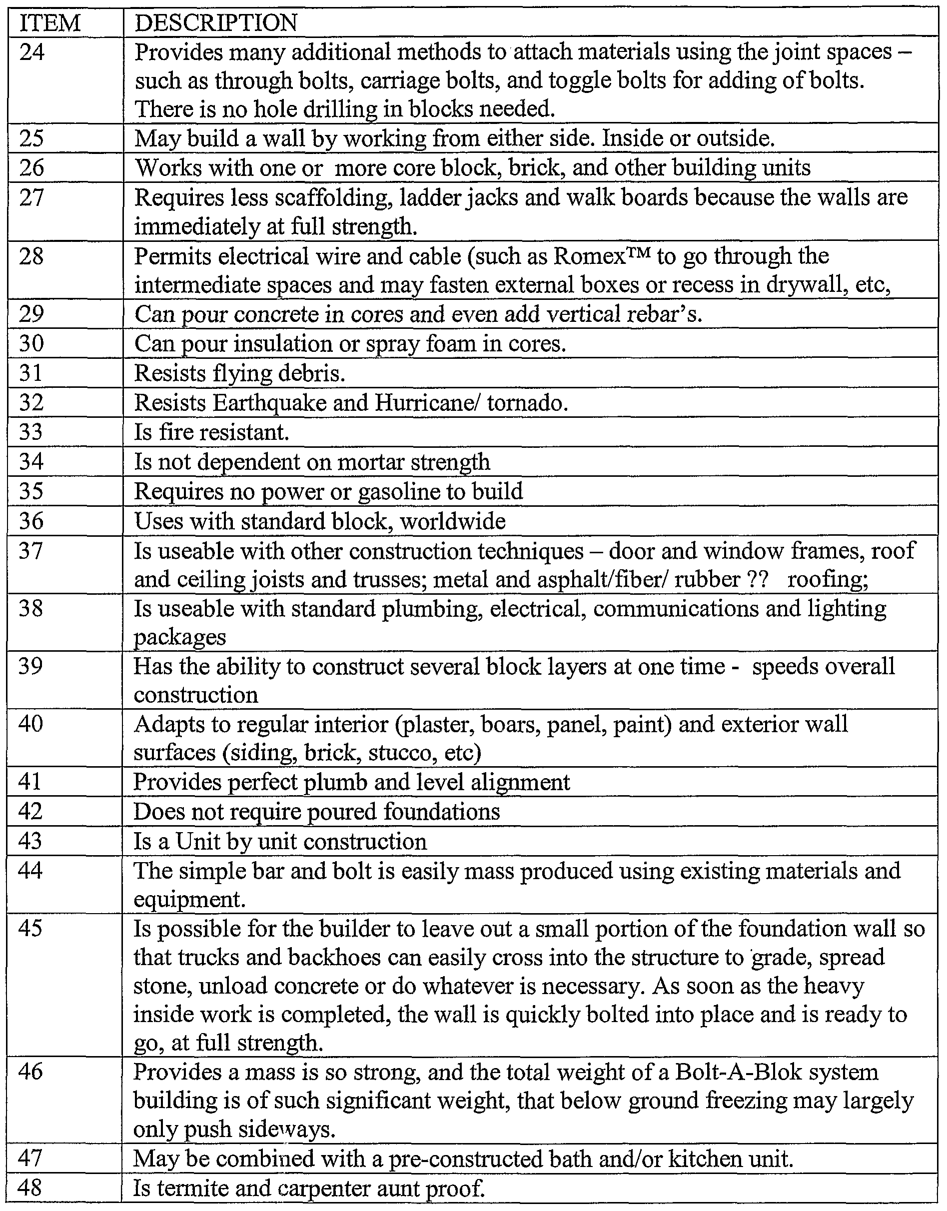
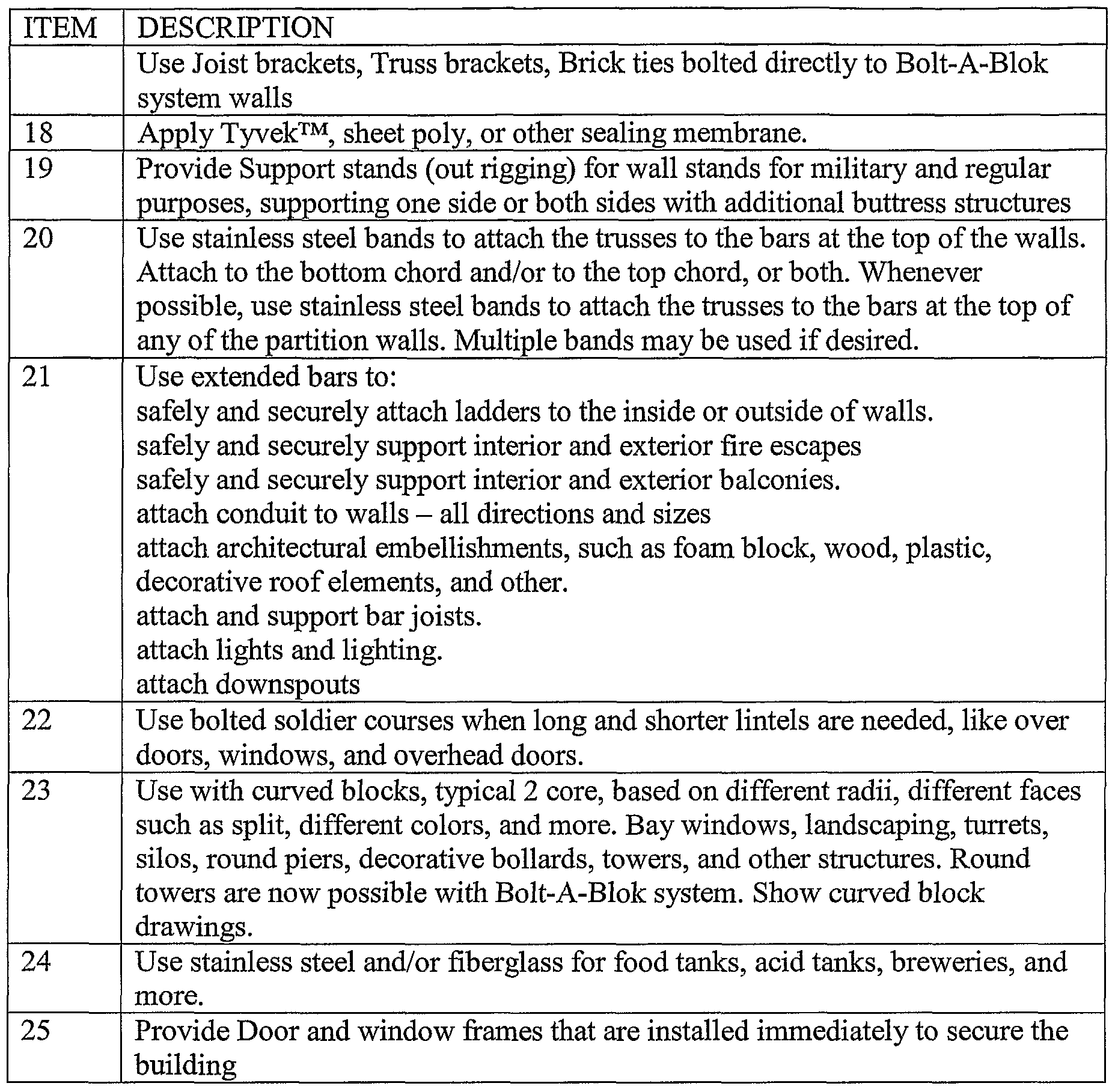
- Table D is offered as exemplary and not limiting as to how this unique Bolt-A-Blok system 31 can be used.
- Bolt-A-Blok system 31 is not to be limited to the disclosed embodiment.
- the features of the Bolt-A-Blok system 31 are intended to cover various modifications and equivalent arrangements included within the spirit and scope of the description.
Abstract
Description


Claims
Priority Applications (6)
| Application Number | Priority Date | Filing Date | Title |
|---|---|---|---|
| MX2008006044A MX2008006044A (en) | 2005-11-10 | 2006-05-05 | Bolt-a-blok - a system for unitized, post-tensioned masonry structures. |
| AU2006317674A AU2006317674A1 (en) | 2005-11-10 | 2006-05-05 | Bolt-a-blok - a system for unitized, post-tensioned masonry structures |
| JP2008540005A JP2009516100A (en) | 2005-11-10 | 2006-05-05 | Bolt-a-block system for integrated post-tension masonry structures |
| EP06759134A EP1945879A2 (en) | 2005-11-10 | 2006-05-05 | Bolt-a-blok - a system for unitized, post-tensioned masonry structures |
| BRPI0618289-5A BRPI0618289A2 (en) | 2005-11-10 | 2006-05-05 | building systems |
| CA2627760A CA2627760C (en) | 2005-11-10 | 2006-05-05 | A system for unitized, post-tensioned masonry structures |
Applications Claiming Priority (2)
| Application Number | Priority Date | Filing Date | Title |
|---|---|---|---|
| US11/271,703 US7934345B2 (en) | 2005-11-10 | 2005-11-10 | Systems for building construction by attaching blocks with bolts and vertically spaced flat bars |
| US11/271,703 | 2005-11-10 |
Publications (2)
| Publication Number | Publication Date |
|---|---|
| WO2007061443A2 true WO2007061443A2 (en) | 2007-05-31 |
| WO2007061443A3 WO2007061443A3 (en) | 2007-09-27 |
Family
ID=38039298
Family Applications (1)
| Application Number | Title | Priority Date | Filing Date |
|---|---|---|---|
| PCT/US2006/017364 WO2007061443A2 (en) | 2005-11-10 | 2006-05-05 | Bolt-a-blok - a system for unitized, post-tensioned masonry structures |
Country Status (11)
| Country | Link |
|---|---|
| US (1) | US7934345B2 (en) |
| EP (1) | EP1945879A2 (en) |
| JP (1) | JP2009516100A (en) |
| KR (1) | KR20080065290A (en) |
| CN (1) | CN101305140A (en) |
| AU (1) | AU2006317674A1 (en) |
| BR (1) | BRPI0618289A2 (en) |
| CA (1) | CA2627760C (en) |
| MX (1) | MX2008006044A (en) |
| RU (1) | RU2402661C2 (en) |
| WO (1) | WO2007061443A2 (en) |
Families Citing this family (46)
| Publication number | Priority date | Publication date | Assignee | Title |
|---|---|---|---|---|
| US8893447B1 (en) * | 2012-12-05 | 2014-11-25 | J Kevin Harris | Use devices for mechanically secured block assembly systems |
| US9206597B2 (en) * | 2006-02-13 | 2015-12-08 | 3B Construction Solutions, Inc. | Unitized post tension block system for masonry structures |
| GB0611213D0 (en) * | 2006-06-07 | 2006-07-19 | Wozair Ltd | Blast wave damper |
| WO2008057778A2 (en) | 2006-10-27 | 2008-05-15 | Marsh Roger F | Post tension block system with superstrongbloks |
| US7774990B1 (en) * | 2006-12-21 | 2010-08-17 | Tom Castellanos | Roof hip and ridge anchor device (CIP) |
| US9206599B2 (en) * | 2007-02-02 | 2015-12-08 | Les Materiaux De Construction Oldcastle Canada, Inc. | Wall with decorative facing |
| WO2008131288A2 (en) * | 2007-04-19 | 2008-10-30 | Marsh Roger F | Special and improved configurations for unitized post tension block system for masonry structures |
| US20100037555A1 (en) * | 2008-05-15 | 2010-02-18 | Fsn, Llc | System and Method For Precision Grinding and Self-Leveling Installation of Concrete Masonry Systems |
| WO2011014865A1 (en) * | 2009-07-31 | 2011-02-03 | Fsn, Llc | Precision ground concrete masonry blocks and system and method for the high-speed application of mortar/grout to precision ground concrete masonry blocks and self-leveling installation of concrete masonry systems |
| US8839593B2 (en) * | 2010-02-17 | 2014-09-23 | Ply Gem Industries, Inc. | Pre-cast blocks for use in column construction |
| KR101078991B1 (en) * | 2010-04-28 | 2011-11-01 | 김유지 | Precast concreat structure and method of constructing the same |
| RU2544346C2 (en) * | 2010-11-26 | 2015-03-20 | Терр Армэ Энтернасьональ | Lining element with its inherent compressibility |
| US9719256B2 (en) | 2011-02-25 | 2017-08-01 | Joe's Eats, Llc | Apparatus and methods for truss assembly |
| US8667750B2 (en) * | 2011-08-09 | 2014-03-11 | Tie-Cast Systems, Inc. | Masonry reinforcement system |
| TR201112282A2 (en) * | 2011-12-12 | 2012-07-23 | Renco Kompoz�T Teknoloj�Ler� Sanay� Ve T�Caret L�M�Ted ��Rket� | A kind of reinforcing element used in building elements. |
| CN102913028B (en) * | 2012-02-01 | 2016-01-27 | 于天庆 | A kind of concrete electric pole and other prefabricated concrete elements gently can taking prestressing force assembling on the spot |
| US8341907B1 (en) * | 2012-04-09 | 2013-01-01 | Gourley Mervin D | Structurally reinforced modular buildings |
| DE102012104116A1 (en) * | 2012-05-10 | 2013-11-14 | Aicheler & Braun Gmbh | foundation system |
| CN102839600B (en) * | 2012-07-30 | 2014-07-09 | 东南大学 | Steel structure connecting device of wood-stone composite bridge |
| CN102776893B (en) * | 2012-08-16 | 2015-02-11 | 中铁大桥局集团有限公司 | Combined type concrete unit foundation |
| US20150052841A1 (en) * | 2013-02-05 | 2015-02-26 | Tindall Corporation | Structure including non-structural joint |
| PL2959065T3 (en) | 2013-02-25 | 2024-04-08 | Les Matériaux De Construction Oldcastle Canada, Inc. | Wall assembly |
| CA2922017C (en) | 2013-08-22 | 2021-10-12 | Tindall Corporation | Tower with assembled blocks |
| AU2013234352B2 (en) * | 2013-09-24 | 2016-02-25 | Wilmott, Reginald Claude | Multi. Use. Brick. |
| US10364569B2 (en) * | 2014-01-23 | 2019-07-30 | Harvel K. Crumley | Guide device for retaining ties in masonry walls |
| US9297176B2 (en) * | 2014-01-23 | 2016-03-29 | Harvel K. Crumley | System and method for retrofitting walls with retaining ties |
| RU2557275C1 (en) * | 2014-02-25 | 2015-07-20 | Михаил Федорович Егоров | Building structure consisting of blocks and its erection method |
| US9194125B1 (en) * | 2014-09-12 | 2015-11-24 | Sergei V. Romanenko | Construction component having embedded internal support structures to provide enhanced structural reinforcement and improved ease of construction therewith |
| US9523201B2 (en) * | 2014-09-12 | 2016-12-20 | Sergei V. Romanenko | Construction components having embedded internal support structures to provide enhanced structural reinforcement for, and improved ease in construction of, walls comprising same |
| CN104278636A (en) * | 2014-09-15 | 2015-01-14 | 宁夏煤炭基本建设有限公司 | Quick building technology for ordinary highway bridge |
| GB2537480B (en) * | 2015-03-06 | 2017-10-04 | Carbon Cut Holdings Ltd | Method and apparatus for intercepting water in a cavity wall |
| US10415241B2 (en) | 2016-03-08 | 2019-09-17 | Excel Project Management Ltd. | Monolithic retaining wall |
| US10584502B2 (en) | 2016-09-09 | 2020-03-10 | Excel Project Management Ltd. | Arch-support system |
| MX2019009636A (en) * | 2017-02-15 | 2019-11-08 | Tindall Corp | Methods and apparatuses for constructing a concrete structure. |
| RU172864U1 (en) * | 2017-03-13 | 2017-07-28 | Марат Георгиевич Калаев | SUPPORT WALL UNIT |
| US9938713B1 (en) * | 2017-05-05 | 2018-04-10 | 3B Construction Solutions, Inc. | Mechanically secured block building system having a pipe opening therethrough |
| US20190017289A1 (en) * | 2017-07-13 | 2019-01-17 | Stanley Ray Wilhelm | Stackable Reinforced Concrete Post for Various Outdoor Applications |
| US11015366B2 (en) * | 2017-07-13 | 2021-05-25 | Stanley Ray Wilhelm | Stackable reinforced concrete post for various outdoor applications |
| US10760273B1 (en) * | 2018-01-17 | 2020-09-01 | Alexander Innovations, Llc | Apparatus and methods for providing continuous structural support to footings and interconnected hollow core wall units |
| BR102018003399B1 (en) * | 2018-02-21 | 2019-11-05 | Fernandes Dos Reis Celmo | prefabricated brick building and assembly process of this building |
| US11041320B2 (en) | 2018-05-15 | 2021-06-22 | Innovative Brick Systems, Llc | Method for creating a precast concrete wall with adjustable concrete form liner connection |
| RU2696730C1 (en) * | 2018-09-13 | 2019-08-05 | Акционерное общество "Научно-исследовательский центр "Строительство", АО "НИЦ "Строительство" | Method of erection of large-panel buildings and structures |
| US11686063B2 (en) * | 2019-12-12 | 2023-06-27 | Robert Daggett | Interlocking blocking system for retaining walls and other uses |
| US11951652B2 (en) | 2020-01-21 | 2024-04-09 | Tindall Corporation | Grout vacuum systems and methods |
| CA3121067C (en) * | 2020-09-15 | 2022-08-30 | Ghassan Marjaba | Building construction system |
| CN112538918A (en) * | 2020-12-26 | 2021-03-23 | 邯郸绿建环保科技有限公司 | Novel wall body assembly module and assembly method thereof |
Citations (4)
| Publication number | Priority date | Publication date | Assignee | Title |
|---|---|---|---|---|
| US5007218A (en) * | 1984-04-12 | 1991-04-16 | Superlite Builders Supply, Inc. | Masonry block wall system and method |
| US6098357A (en) * | 1994-11-07 | 2000-08-08 | Megawall Corporation | Modular precast construction block system |
| US6513296B1 (en) * | 1999-05-20 | 2003-02-04 | Steffen Baden | Wall anchor for reinforcing and/or securing walls |
| US6632048B2 (en) * | 1999-06-14 | 2003-10-14 | Pyramid Retaining Walls, Llc | Masonry retainer wall system and method |
Family Cites Families (58)
| Publication number | Priority date | Publication date | Assignee | Title |
|---|---|---|---|---|
| US838844A (en) * | 1905-05-17 | 1906-12-18 | John Horrocks Clayton | Building-block. |
| US962463A (en) * | 1909-03-10 | 1910-06-28 | Lee Phillips | Building-block. |
| US952305A (en) * | 1909-06-02 | 1910-03-15 | Clarence A Buskirk | Concrete block. |
| US1753451A (en) * | 1927-07-27 | 1930-04-08 | Tonnelier John Edmund | Wall |
| US1783383A (en) * | 1928-06-19 | 1930-12-02 | James V Montrief | Building construction |
| US1892605A (en) * | 1931-10-20 | 1932-12-27 | Betzler Paul | Wall construction |
| US2141397A (en) * | 1937-09-14 | 1938-12-27 | Locke Earl Ray | Building system |
| US2212184A (en) * | 1938-12-07 | 1940-08-20 | Angle W Powell | Building unit |
| US2250763A (en) * | 1939-11-08 | 1941-07-29 | Raymond L Hild | Reinforced wall and foundation structure |
| US2929236A (en) * | 1955-03-29 | 1960-03-22 | Steward Construction Company | Building wall construction |
| US2963828A (en) * | 1957-06-13 | 1960-12-13 | Philip J Belliveau | Building blocks and means for assembling same |
| US3295286A (en) * | 1961-05-31 | 1967-01-03 | Owens Illinois Inc | Cementitious slab with bolt means |
| US3236545A (en) * | 1961-07-20 | 1966-02-22 | George L Parkes | Cam bushing for conduits |
| US3296758A (en) * | 1963-06-28 | 1967-01-10 | Kirkkejner O Knudsen | Superimposed building blocks with vertically spaced flat bars interfitted therewith connected by threaded stud members |
| US3410044A (en) * | 1965-07-23 | 1968-11-12 | Contemporary Walls Ltd | Foamed plastic based construction elements |
| US3382632A (en) * | 1965-07-28 | 1968-05-14 | Paul W. Grofcsik | Compressed, interlocked block wall |
| US3511000A (en) * | 1968-08-08 | 1970-05-12 | Henry P C Keuls | Interlocking hollow building blocks |
| US3763609A (en) * | 1972-08-03 | 1973-10-09 | Pal Dev Corp | Shingle roofing construction |
| US3785097A (en) * | 1972-11-06 | 1974-01-15 | W Seymour | Adjustable anchor bolt & block building and leveling means |
| DE2525579A1 (en) * | 1975-06-09 | 1976-12-30 | Hilti Ag | ADHESIVE ANCHORS |
| US4569167A (en) * | 1983-06-10 | 1986-02-11 | Wesley Staples | Modular housing construction system and product |
| US4640071A (en) * | 1985-07-12 | 1987-02-03 | Juan Haener | Interlocking building block |
| US4726567A (en) * | 1986-09-16 | 1988-02-23 | Greenberg Harold H | Masonry fence system |
| US4757656A (en) * | 1987-11-19 | 1988-07-19 | Powers Jr John A | Lintel system |
| US4854097A (en) * | 1988-02-01 | 1989-08-08 | Juan Haener | Insulated interlocking building blocks |
| US5294216A (en) * | 1989-09-28 | 1994-03-15 | Anchor Wall Systems, Inc. | Composite masonry block |
| US5511902A (en) * | 1994-02-09 | 1996-04-30 | Center; Leslie T. | Instant levy block system |
| US5678373A (en) * | 1994-11-07 | 1997-10-21 | Megawall Corporation | Modular precast wall system with mortar joints |
| CA2158771C (en) * | 1995-09-21 | 1999-08-10 | David W. Fielding | Drywall construction and means therefor |
| US5941565A (en) * | 1996-10-01 | 1999-08-24 | Clendenin, Jr.; J. Gregg | Vehicle traction enhancing apparatus |
| US6244785B1 (en) * | 1996-11-12 | 2001-06-12 | H. B. Zachry Company | Precast, modular spar system |
| US6557316B2 (en) * | 1997-04-21 | 2003-05-06 | Franciscus Antonius Maria Van Der Heijden | Building system comprising individual building elements |
| NL1005850C2 (en) * | 1997-04-21 | 1998-10-27 | Franciscus Antonius Maria Van | Building system comprising separate building elements. |
| US6065265A (en) * | 1997-05-01 | 2000-05-23 | Newtec Building Products Inc. | Corner and end block for interlocking building block system |
| US5809732A (en) * | 1997-08-08 | 1998-09-22 | Ccc Group, Inc. | M/bed block system |
| IT1297654B1 (en) * | 1997-09-02 | 1999-12-20 | Salvatore Trovato | SYSTEM FOR THE CONSTRUCTION OF LOAD-BEARING AND NON-LOADING WALLS, WITH VARIABLE THICKNESS, INSULATED AND WITH FINISHED PARAMENTS, BY ASSEMBLING A |
| US6758020B2 (en) * | 1997-09-08 | 2004-07-06 | Cercorp Initiatives Incorporated | Flexible interlocking wall system |
| US6167669B1 (en) * | 1997-11-03 | 2001-01-02 | Louis Joseph Lanc | Concrete plastic unit CPU |
| US6138426A (en) * | 1997-11-22 | 2000-10-31 | Mork; Robert James | Mortarless wall |
| US6976345B2 (en) * | 1999-04-05 | 2005-12-20 | Firouzeh Keshmiri | Cementitious based structural lumber product and externally reinforced lightweight retaining wall system |
| US6431797B2 (en) * | 1999-06-14 | 2002-08-13 | Pyramid Retaining Walls, Llc | Masonry retainer wall system and method |
| US6178714B1 (en) * | 1999-07-06 | 2001-01-30 | Robert S. Carney, Jr. | Modular temporary building |
| US6374552B1 (en) * | 2000-04-12 | 2002-04-23 | Alliance Concrete Concepts, Inc. | Skirting wall system |
| US6665992B2 (en) * | 2000-05-03 | 2003-12-23 | Anthony Alexander Hew | Concrete construction block and method for forming the same |
| DE10041679A1 (en) * | 2000-08-24 | 2002-03-07 | Daimler Chrysler Ag | Device for controlling an internal combustion engine driving a utility unit |
| JP3749825B2 (en) * | 2000-09-06 | 2006-03-01 | 独立行政法人科学技術振興機構 | Brick masonry structure, brick masonry construction method and brick |
| US6955015B2 (en) * | 2002-04-29 | 2005-10-18 | Redi-Rock International, Llc | System for interconnecting wall blocks |
| US6904728B2 (en) * | 2003-01-14 | 2005-06-14 | Heritage Log Homes, Inc. | Log home construction system |
| US7461490B2 (en) * | 2003-01-23 | 2008-12-09 | Omar Toledo | Construction block system |
| US20050183362A1 (en) * | 2003-07-14 | 2005-08-25 | Mccarthy Brian P. | Concealed elevated post base bracket |
| US7415805B2 (en) * | 2003-12-08 | 2008-08-26 | Nickerson David L | Wall system with masonry external surface and associated method |
| US7124550B1 (en) * | 2004-04-14 | 2006-10-24 | Richard Allen Deming | Anchoring framework to a masonry wall |
| US7849650B2 (en) * | 2005-01-27 | 2010-12-14 | United States Gypsum Company | Non-combustible reinforced cementitious lightweight panels and metal frame system for a fire wall and other fire resistive assemblies |
| EP1846629A2 (en) * | 2005-02-10 | 2007-10-24 | Westblock Systems, Inc. | Masonry block wall system |
| CA2511630C (en) * | 2005-07-06 | 2008-10-14 | Gc Engineering Ltd | Masonry wall system |
| US20070056235A1 (en) * | 2005-09-12 | 2007-03-15 | Kohler Michael E | Post-tension cable wall stabilization |
| US9206597B2 (en) * | 2006-02-13 | 2015-12-08 | 3B Construction Solutions, Inc. | Unitized post tension block system for masonry structures |
| WO2008131288A2 (en) * | 2007-04-19 | 2008-10-30 | Marsh Roger F | Special and improved configurations for unitized post tension block system for masonry structures |
-
2005
- 2005-11-10 US US11/271,703 patent/US7934345B2/en not_active Expired - Fee Related
-
2006
- 2006-05-05 EP EP06759134A patent/EP1945879A2/en not_active Withdrawn
- 2006-05-05 AU AU2006317674A patent/AU2006317674A1/en not_active Abandoned
- 2006-05-05 JP JP2008540005A patent/JP2009516100A/en active Pending
- 2006-05-05 RU RU2008123521/03A patent/RU2402661C2/en not_active IP Right Cessation
- 2006-05-05 MX MX2008006044A patent/MX2008006044A/en not_active Application Discontinuation
- 2006-05-05 KR KR1020087011207A patent/KR20080065290A/en not_active Application Discontinuation
- 2006-05-05 BR BRPI0618289-5A patent/BRPI0618289A2/en not_active IP Right Cessation
- 2006-05-05 CA CA2627760A patent/CA2627760C/en not_active Expired - Fee Related
- 2006-05-05 WO PCT/US2006/017364 patent/WO2007061443A2/en active Application Filing
- 2006-05-05 CN CNA2006800420783A patent/CN101305140A/en active Pending
Patent Citations (5)
| Publication number | Priority date | Publication date | Assignee | Title |
|---|---|---|---|---|
| US5007218A (en) * | 1984-04-12 | 1991-04-16 | Superlite Builders Supply, Inc. | Masonry block wall system and method |
| US5007218B1 (en) * | 1984-04-12 | 1996-04-16 | Superlite Block | Masonry block wall system and method |
| US6098357A (en) * | 1994-11-07 | 2000-08-08 | Megawall Corporation | Modular precast construction block system |
| US6513296B1 (en) * | 1999-05-20 | 2003-02-04 | Steffen Baden | Wall anchor for reinforcing and/or securing walls |
| US6632048B2 (en) * | 1999-06-14 | 2003-10-14 | Pyramid Retaining Walls, Llc | Masonry retainer wall system and method |
Also Published As
| Publication number | Publication date |
|---|---|
| RU2402661C2 (en) | 2010-10-27 |
| CA2627760A1 (en) | 2007-05-31 |
| CA2627760C (en) | 2011-06-14 |
| US7934345B2 (en) | 2011-05-03 |
| KR20080065290A (en) | 2008-07-11 |
| RU2008123521A (en) | 2009-12-20 |
| EP1945879A2 (en) | 2008-07-23 |
| BRPI0618289A2 (en) | 2011-08-30 |
| JP2009516100A (en) | 2009-04-16 |
| CN101305140A (en) | 2008-11-12 |
| US20070107333A1 (en) | 2007-05-17 |
| MX2008006044A (en) | 2008-10-01 |
| WO2007061443A3 (en) | 2007-09-27 |
| AU2006317674A1 (en) | 2007-05-31 |
Similar Documents
| Publication | Publication Date | Title |
|---|---|---|
| EP1945879A2 (en) | Bolt-a-blok - a system for unitized, post-tensioned masonry structures | |
| RU2402660C2 (en) | Unified system of building blocks with further stressing to erect stone structures | |
| CN102959162B (en) | Prefabricated wall panels | |
| US8099918B2 (en) | Special and improved configurations for unitized post tension block systems for masonry structures | |
| US6434900B1 (en) | Prefabricated concrete wall system | |
| US7409800B2 (en) | Structural thermal framing and panel system for assembling finished or unfinished walls with multiple panel combinations for poured and nonpoured wall | |
| US4219978A (en) | Pre-cast reinforced concrete building panel wall structure | |
| US20150308096A1 (en) | Methods, systems and components for multi-storey building construction | |
| US20080098687A1 (en) | Super unitized post tension block system for high high strength masonry structures - with SuperStrongBloks | |
| US20150204085A1 (en) | Wall assembly and a building structure including the wall assembly | |
| US7219474B2 (en) | Load bearing building panel | |
| WO2011127522A1 (en) | A method of forming a structural element and a method of building a structure | |
| CN104652662B (en) | Prefabricated panel system | |
| JPH09235801A (en) | Beam erect construction method of block laying structure | |
| US20220356705A1 (en) | Pre-stressed insulated concrete panels and methods for making and using the same | |
| AU2002301430B2 (en) | A building construction | |
| AU750020B3 (en) | A load bearing building panel | |
| AU2002234421B2 (en) | A load bearing building panel | |
| US6829870B2 (en) | Building methods | |
| JPS6062354A (en) | Construction of synthetic earthquake-proof wall |
Legal Events
| Date | Code | Title | Description |
|---|---|---|---|
| WWE | Wipo information: entry into national phase |
Ref document number: 200680042078.3 Country of ref document: CN |
|
| 121 | Ep: the epo has been informed by wipo that ep was designated in this application | ||
| ENP | Entry into the national phase |
Ref document number: 2627760 Country of ref document: CA |
|
| WWE | Wipo information: entry into national phase |
Ref document number: 2006759134 Country of ref document: EP |
|
| WWE | Wipo information: entry into national phase |
Ref document number: 2006317674 Country of ref document: AU |
|
| WWE | Wipo information: entry into national phase |
Ref document number: 191292 Country of ref document: IL Ref document number: 3870/DELNP/2008 Country of ref document: IN |
|
| ENP | Entry into the national phase |
Ref document number: 2008540005 Country of ref document: JP Kind code of ref document: A |
|
| WWE | Wipo information: entry into national phase |
Ref document number: MX/a/2008/006044 Country of ref document: MX |
|
| WWE | Wipo information: entry into national phase |
Ref document number: 1020087011207 Country of ref document: KR |
|
| NENP | Non-entry into the national phase |
Ref country code: DE |
|
| ENP | Entry into the national phase |
Ref document number: 2006317674 Country of ref document: AU Date of ref document: 20060505 Kind code of ref document: A |
|
| WWE | Wipo information: entry into national phase |
Ref document number: 2008123521 Country of ref document: RU |
|
| ENP | Entry into the national phase |
Ref document number: PI0618289 Country of ref document: BR Kind code of ref document: A2 Effective date: 20080506 |