WO2006025404A1 - 状態検出装置及び状態検出方法並びに状態検出用プログラム及び情報記録媒体、状態表示装置及び状態表示方法並びに状態表示用プログラム及び情報記録媒体 - Google Patents
状態検出装置及び状態検出方法並びに状態検出用プログラム及び情報記録媒体、状態表示装置及び状態表示方法並びに状態表示用プログラム及び情報記録媒体 Download PDFInfo
- Publication number
- WO2006025404A1 WO2006025404A1 PCT/JP2005/015792 JP2005015792W WO2006025404A1 WO 2006025404 A1 WO2006025404 A1 WO 2006025404A1 JP 2005015792 W JP2005015792 W JP 2005015792W WO 2006025404 A1 WO2006025404 A1 WO 2006025404A1
- Authority
- WO
- WIPO (PCT)
- Prior art keywords
- parameter
- detection
- generated
- value
- rolling
- Prior art date
- Legal status (The legal status is an assumption and is not a legal conclusion. Google has not performed a legal analysis and makes no representation as to the accuracy of the status listed.)
- Ceased
Links
Classifications
-
- F—MECHANICAL ENGINEERING; LIGHTING; HEATING; WEAPONS; BLASTING
- F16—ENGINEERING ELEMENTS AND UNITS; GENERAL MEASURES FOR PRODUCING AND MAINTAINING EFFECTIVE FUNCTIONING OF MACHINES OR INSTALLATIONS; THERMAL INSULATION IN GENERAL
- F16C—SHAFTS; FLEXIBLE SHAFTS; ELEMENTS OR CRANKSHAFT MECHANISMS; ROTARY BODIES OTHER THAN GEARING ELEMENTS; BEARINGS
- F16C29/00—Bearings for parts moving only linearly
- F16C29/04—Ball or roller bearings
- F16C29/06—Ball or roller bearings in which the rolling bodies circulate partly without carrying load
- F16C29/0633—Ball or roller bearings in which the rolling bodies circulate partly without carrying load with a bearing body defining a U-shaped carriage, i.e. surrounding a guide rail or track on three sides
-
- F—MECHANICAL ENGINEERING; LIGHTING; HEATING; WEAPONS; BLASTING
- F16—ENGINEERING ELEMENTS AND UNITS; GENERAL MEASURES FOR PRODUCING AND MAINTAINING EFFECTIVE FUNCTIONING OF MACHINES OR INSTALLATIONS; THERMAL INSULATION IN GENERAL
- F16C—SHAFTS; FLEXIBLE SHAFTS; ELEMENTS OR CRANKSHAFT MECHANISMS; ROTARY BODIES OTHER THAN GEARING ELEMENTS; BEARINGS
- F16C29/00—Bearings for parts moving only linearly
-
- G—PHYSICS
- G01—MEASURING; TESTING
- G01M—TESTING STATIC OR DYNAMIC BALANCE OF MACHINES OR STRUCTURES; TESTING OF STRUCTURES OR APPARATUS, NOT OTHERWISE PROVIDED FOR
- G01M13/00—Testing of machine parts
- G01M13/04—Bearings
- G01M13/045—Acoustic or vibration analysis
-
- F—MECHANICAL ENGINEERING; LIGHTING; HEATING; WEAPONS; BLASTING
- F16—ENGINEERING ELEMENTS AND UNITS; GENERAL MEASURES FOR PRODUCING AND MAINTAINING EFFECTIVE FUNCTIONING OF MACHINES OR INSTALLATIONS; THERMAL INSULATION IN GENERAL
- F16C—SHAFTS; FLEXIBLE SHAFTS; ELEMENTS OR CRANKSHAFT MECHANISMS; ROTARY BODIES OTHER THAN GEARING ELEMENTS; BEARINGS
- F16C2233/00—Monitoring condition, e.g. temperature, load, vibration
Definitions
- Status detection device status detection method, status detection program and information recording medium
- status display device status display method, status display program and information recording medium
- the present invention belongs to the technical field of a state detection device, a state detection method, a state detection program, and an information recording medium, and more specifically, the linear motion rolling during the operation of the linear motion rolling guide device.
- the present invention belongs to the technical field of a status display device, a status display method, a status display program, and an information recording medium, and more specifically, the linear motion during the operation of the linear motion rolling guide device.
- a state display device and a state display method for displaying an operation state of a rolling guide device a state display program for displaying the operation state, and an information recording medium in which the state display program is recorded in a computer-readable manner Belongs.
- a rail, a moving block that moves in the longitudinal direction on the rail, and a circulation (revolution) while interposing between the rail and the moving block are rotating (spinning).
- a so-called linear motion rolling guide device including a plurality of balls (rolling elements) for moving the moving block with high accuracy is widely used.
- the range of use has expanded to support three-dimensional motion, pendulum motion in pendulum trains, and even seismic isolation structures in buildings.
- the linear motion rolling guide device there is a so-called ball screw in addition to the above-described moving block and rail.
- a vibration of the mechanical system is used as a method for diagnosing the operation state in a conventional general mechanical system (for example, a rolling bearing device for rotation including ball bearings) excluding the linear motion rolling guide device.
- Vibration detection method for monitoring the state of occurrence and diagnosing the operating state oil evaluation method for diagnosing the operating state by taking out the lubricating oil used in the machine system and evaluating its quality
- the machine Electrical resistance method for diagnosing operating conditions by measuring electrical resistance between members driven through lubricant in the system, or member driven via lubricant in the mechanical system
- the vibration detection method when used, in the linear motion rolling guide device, the ball as a rolling element revolves around the circulation section while rotating by itself, so there are many sources of vibration. There was a problem that the vibration caused by the abnormal operating state should not be detected accurately.
- the present invention has been made in view of the above-described problems, and its problem is that the linear motion rolling guide device can accurately detect in real time the motion state of the linear motion rolling guide device. It is possible to predict the occurrence of a failure in the guide device, improve the maintainability of the user of the linear motion rolling guide device, and further improve the service life and performance of the device or equipment incorporating the linear motion rolling guide device.
- Status detection device and status detection method capable of contributing to guarantee and quality improvement thereof, status detection program for detecting the operating status, and information recording medium on which the status detection program is recorded so as to be readable by a computer Is to provide.
- the problem of the present invention is that it is possible to predict the occurrence of a failure in the linear motion rolling guide device by accurately displaying the operation state in the linear motion rolling guide device in real time, and the linear motion Status display device capable of improving serviceability for the user of the rolling guide device, further extending its service life, guaranteeing the performance of the device or equipment incorporating the linear motion rolling guide device, and improving the quality thereof, and A state display method, a state display program for detecting the operation state, and a state display program are provided. An information recording medium recorded so as to be readable by a computer is provided.
- the invention according to claim 1 is a state detection device that detects a current operation state in the linear motion rolling guide device, and includes the linear motion rolling guide device. Collision between the rolling surface included in the linear rolling guide device and the rolling element, which occurs when the plurality of included rolling elements revolve in the circulation section while rotating, and the rolling surface and the rolling element Due to at least one of a slip in the contact portion, a collision between the rolling elements, a slip in the contact portion between the rolling elements, or a crack generated in at least one of the rolling element or the rolling surface.
- Detection means such as an acoustic emission (AE) sensor that detects an inertially generated wave and generates an electrical detection signal corresponding to the detected wave, and the wave based on the generated detection signal.
- Strength of The first generation means such as a signal processing unit for generating the first parameter and the value of the generated first parameter are preset for the first parameter, and the first threshold is less than the value.
- Determination means such as a signal processing unit for determining that the operation state is normal when the value is a value And comprising.
- the linear motion rolling is performed. Since the operation state of the in-house device is determined to be normal, vibration or external drive caused by the operation without disassembling the linear motion rolling guide device in real time during the operation of the linear motion rolling guide device It is possible to detect whether or not the operating state is normal while eliminating the influence of vibration and the like caused by the device.
- the invention according to claim 2 is the state detection device according to claim 1, wherein the time detection device includes the time signal based on the generated detection signal.
- a second generation unit such as a signal processing unit that generates a second parameter by weighting only the detection signal continuously detected, and the conversion signal among the detection signals based on the generated detection signal.
- a third generation unit such as a signal processing unit that generates a third parameter by weighting only the detection signal detected discontinuously in time corresponding to the motion of the moving body, and the determination unit includes: When the value of the generated first parameter is greater than or equal to the first threshold value, the content is determined using at least one of the second parameter or the third parameter. Configured.
- the content of the operating state is determined using the second parameter or the third parameter different from the first parameter. In detail, it is possible to determine and detect a specific content of the operation state.
- the invention according to claim 3 is the state detection device according to claim 2, wherein the first parameter P is a measurement obtained by sampling the detection signal.
- the value is N and the total number of the measured values is
- the third parameter P is further used as the measured value.
- the invention according to claim 4 is the state detection device according to claim 2 or 3, wherein the determination means is configured such that the value of the generated first parameter is The value of the second threshold value is equal to or greater than the first threshold value, and the value of the generated second parameter is set in advance for the second parameter!
- the operation state is determined to be a poor lubrication state.
- the value of the first parameter is greater than or equal to the first threshold value
- the value of the second parameter is greater than the second threshold value
- the value of the third parameter is greater than the third threshold value.
- the invention according to claim 5 is the state detection apparatus according to claim 2 or 3, wherein the determination means is configured such that the value of the generated first parameter is The value of the second threshold value is equal to or greater than the first threshold value, and the value of the generated second parameter is set in advance for the second parameter!
- the operating condition is that liquid other than the lubricant is mixed in the circulation section! It is configured to determine that it is in a state of operating.
- the value of the first parameter is greater than or equal to the first threshold value
- the value of the second parameter is greater than the second threshold value
- the value of the third parameter is greater than the third threshold value.
- the invention according to claim 6 is the state detection device according to claim 2 or 3, wherein the determination means is configured such that the value of the generated first parameter is The value of the second parameter is not less than the first threshold value and the value of the generated second parameter is preset for the second parameter !, the second threshold value is less than the value, and When the value of the generated third parameter is not less than the third threshold value set in advance for the third parameter, the operation state is at least the rolling surface or the rolling element! / In other words, it is determined that a crack has occurred and the operation state has been reached.
- the value of the first parameter is a value greater than or equal to the first threshold value
- the value of the second parameter is the second threshold, a value less than the value
- the value of the third parameter is the third threshold.
- the invention according to claim 7 is the state detection device according to any one of claims 1 to 6, wherein any of the determinations made by the determination means is performed. Notification means for notifying the operating state is further provided.
- the invention described in claim 8 is a state detection method for detecting a current operation state in a linear motion rolling guide device, and includes the linear motion rolling guide device.
- This straight line is generated when the included rolling elements revolve around the circulation while rotating. Collision between the rolling contact surface and the rolling element included in the rolling guide device, sliding at the contact portion between the rolling contact surface and the rolling member, or collision between the rolling members or contact portion between the rolling members Electrical detection corresponding to the detected wave is detected by detecting a slip or a wave generated at least due to at least one of the rolling element and a crack generated on the rolling surface.
- the linear motion rolling is performed. Since the operation state of the in-house device is determined to be normal, vibration or external drive caused by the operation without disassembling the linear motion rolling guide device in real time during the operation of the linear motion rolling guide device It is possible to detect whether or not the operating state is normal while eliminating the influence of vibration and the like caused by the device.
- the invention according to claim 9 is the state detection method according to claim 8, wherein the time detection method includes a time signal based on the generated detection signal.
- generating a third parameter by weighting only the detected signals detected discontinuously in time, and in the determination step, the generated first When the parameter value is equal to or greater than the first threshold value, the content is determined using at least one of the second parameter and the third parameter.
- the content of the operating state is determined using the second parameter or the third parameter that is different from the first parameter. In detail, it is possible to determine and detect a specific content of the operation state.
- the invention described in claim 10 is the state described in claim 9.
- the state detection method when the first parameter 1 ⁇ is X, the measurement value obtained by sampling the detection signal is N, and the total number of the measurement values is N (pieces),
- the detection means it is used as the measured value.
- the invention according to claim 11 is the state detection method according to claim 9 or 10, in the determination step, the generated first parameter.
- the value of the second parameter is not less than the first threshold value, and the value of the generated second parameter is preset for the second parameter!
- the value of the generated third parameter is preset for the third parameter and is less than the third threshold value, it is determined that the operation state is a poor lubrication state. Composed.
- the value of the first parameter is greater than or equal to the first threshold
- the value of the second parameter is greater than the second threshold
- the value of the third parameter is greater than the third threshold.
- the invention according to claim 12 is described in claim 9 or 10.
- the value of the generated first parameter is a value equal to or greater than the first threshold value
- the value of the generated second parameter is the value of the first parameter. 2 parameters are set in advance !
- the second threshold is a value greater than or equal to the value
- the value of the generated third parameter is preset for the third parameter
- the third threshold is set.
- the value of the first parameter is greater than or equal to the first threshold value
- the value of the second parameter is greater than the second threshold value
- the value of the third parameter is greater than the third threshold value.
- the invention according to claim 13 is the state detection method according to claim 9 or 10, wherein in the determination step, the generated first parameter is used. And the generated second parameter value is less than a second threshold value set in advance for the second parameter, and the generated value is equal to or greater than the first threshold value.
- the value of the third parameter set is equal to or greater than a third threshold value set in advance for the third parameter, the operating state is cracked at least on the rolling surface or the rolling element. It is configured to determine that an operation state occurs.
- the value of the first parameter is a value greater than or equal to the first threshold
- the value of the second parameter is the second threshold
- the value of the third parameter is the third threshold.
- the invention according to claim 14 is characterized in that, in the state detection method according to any one of claims 8 to 13, the determination step is performed. It is comprised so that the notification process of notifying which said operation state determined may be further included.
- the invention according to claim 15 is directed to a linear motion rolling guide device including a computer included in a state detection device that detects a current operation state in the linear motion rolling guide device. Collision between the rolling surface included in the linear motion rolling guide device and the rolling element, and contact between the rolling surface and the rolling element, which occurs when the included rolling elements revolve in the circulation section while rotating. Due to at least one of a slip at a part, a collision between the rolling elements, a slip at a contact part between the rolling elements, or a crack generated on at least one of the rolling element or the rolling surface.
- Detection means for detecting a wave generated by inertia and generating an electrical detection signal corresponding to the detected wave; a first parameter indicating the intensity of the wave based on the generated detection signal; First generation means for generating data, and based on the generated detection signal, only the detection signal detected continuously in time among the detection signals is weighted to generate the second parameter.
- a second generation means for weighting only the detection signal detected in a time discontinuous manner corresponding to the motion of the rolling element based on the generated detection signal; Function as third generation means for generating parameters, and determination means for determining the content of the operation state using at least one of the generated first parameter, second parameter, or third parameter Configured as follows.
- the computer functions to determine the content of the operation state of the linear motion rolling guide device using at least one of the first parameter, the second parameter, and the third parameter. While operating the rolling guide device, in real time, eliminate the influence of the vibration caused by the operation without disassembling the linear motion rolling guide device, and the contents of the operation state. Can be detected.
- the invention described in claim 16 is the state described in claim 15.
- a state detection program is recorded so as to be readable by the computer.
- the contents of the operation state of the linear motion rolling guide device can be obtained using any of the first parameter, the second parameter, or the third parameter. Since the computer functions so as to determine the vibration caused by the operation and the external drive device without disassembling the linear motion rolling guide device in real time during the operation of the linear motion rolling guide device It is possible to detect the contents of the operation state while eliminating the influence of vibrations and the like due to the above.
- the invention according to claim 17 is a state display device for displaying a current operation state in the linear motion rolling guide device, and is included in the linear motion rolling guide device. Collision between the rolling surface included in the linear motion rolling guide device and the rolling element, which occurs when a plurality of rolling elements revolve in the circulation section while rotating, and at the contact portion between the rolling surface and the rolling element Spontaneously due to at least one of a slip, a collision between the rolling elements, a slip at a contact portion between the rolling elements, or a crack generated on at least one of the rolling element and the rolling surface.
- Detection means such as an AE (Acoustic Emission) sensor that detects the generated wave and generates an electrical detection signal corresponding to the detected wave, and samples the generated detection signal to detect the detection data.
- Sampling means such as a signal processing unit for generating the detection data and a plurality of the detection data obtained within a preset detection time, and Generating a first parameter weighted only with the detection data corresponding to the detection signal detected continuously in time among the detected signals, for each of the plurality of detection data groups corresponding to the different detection times.
- the first generation means such as a signal processing unit and the respective detection data included in the detection data group are temporally corresponding to the motion of the rolling elements of the generated detection signals.
- the second generation means such as a signal processing unit performed for each data group and the value of the first parameter and the value of the second parameter obtained for one detection data group
- the first axis is set to the first axis.
- Display control means such as a signal processing unit for displaying the graph obtained by displaying each detection data group as one plot point for each detection data group on a display means such as a display unit.
- the first axis is the first parameter value and the second axis is the second parameter value.
- Displaying one detection data group as one plot point on the graph shows the graph obtained by performing each detection data group, so that the user who uses the linear motion rolling guide device The current operation state of the linear motion rolling guide device can be recognized.
- the invention according to claim 18 is the status display apparatus according to claim 17, wherein the first parameter P
- the total number of the detection data included in the corresponding detection data group is N (pieces), and the maximum input range in the detection means is a constant K (volts).
- the second parameter P is further detected by the detection data.
- the invention according to claim 19 is a state display method for displaying a current operation state in the linear motion rolling guide device, and is included in the linear motion rolling guide device. Collision between the rolling surface included in the linear motion rolling guide device and the rolling element, which occurs when a plurality of rolling elements revolve in the circulation section while rotating, and at the contact portion between the rolling surface and the rolling element Spontaneously due to at least one of a slip, a collision between the rolling elements, a slip at a contact portion between the rolling elements, or a crack generated on at least one of the rolling element and the rolling surface.
- a detection process for detecting the generated wave and generating an electrical detection signal corresponding to the detected wave and a sampling process for sampling the generated detection signal and generating detection data And in a detection data group composed of a plurality of detection data obtained within a preset detection time, and based on each detection data, continuously generated in time among the generated detection signals.
- the first axis is the first parameter value and the second axis is the second parameter value.
- Displaying one detection data group as one plot point on the graph shows the graph obtained by performing each detection data group, so that the user who uses the linear motion rolling guide device The current operation state of the linear motion rolling guide device can be recognized.
- the invention according to claim 20 is the state display method according to claim 19, wherein the first parameter P
- the total number of the detection data included in the corresponding detection data group is N (pieces), and the maximum input range in the detection means is a constant K (volts).
- the second parameter P is further detected by the detection data.
- the invention according to claim 21 is directed to a linear motion rolling guide device including a computer included in a state display device that displays a current operation state in the linear motion rolling guide device. Collision between the rolling surface included in the linear motion rolling guide device and the rolling element, and contact between the rolling surface and the rolling element, which occurs when the included rolling elements revolve in the circulation section while rotating. Due to at least one of a slip at a part, a collision between the rolling elements, a slip at a contact part between the rolling elements, or a crack generated on at least one of the rolling element or the rolling surface.
- Detecting means for detecting a wave generated by inertia and generating an electric detection signal corresponding to the detected wave; a sampling means for sampling the generated detection signal and generating detection data; Pulling means, based on each detection data included in a detection data group constituted by a plurality of the detection data obtained within a preset detection time, out of the generated detection signals in terms of time.
- the generation of the first parameter weighted only with the detection data corresponding to the detection signals that are continuously detected, the different detection times The first generation means for each of the plurality of detection data groups corresponding to the detection data, corresponding to the motion of the rolling element of the generated detection signals based on the detection data included in the detection data group.
- the first axis is the first parameter value and the second axis is the second parameter value.
- Displaying one detection data group as one plot point on the graph shows that the graph is obtained for each detection data group, so the linear function rolling guide device It is possible to make the user who uses the device recognize the current operation state of the linear motion rolling guide device.
- the invention according to claim 22 is recorded so as to be readable by the computer according to claim 21.
- the first axis is changed to the first axis using the first parameter value and the second parameter value obtained for one detection data group. Displaying one detection data group as one plot point on the graph with one parameter value and the second axis as the second parameter value is displayed for each detection data group. Since the computer functions as described above, the user who uses the linear motion rolling guide device can recognize the current operating state of the linear motion rolling guide device.
- the first parameter indicating the intensity of the wave generated elastically by the operation of the linear motion rolling guide device is generated, and the value is less than the first threshold value. value Therefore, it is determined that the operation state of the linear motion rolling guide device is normal. Therefore, the operation without disassembling the linear motion rolling guide device in real time during the operation of the linear motion rolling guide device. It is possible to detect whether or not the operating state is normal force while eliminating the effects of vibration caused by the vibration and vibration caused by the external drive device.
- the occurrence of a failure in the linear motion rolling guide device can be predicted, and the maintainability of the linear motion rolling guide device for the user is improved, the service life of the linear motion rolling guide device is increased, and the linear motion rolling guide device is used. It contributes to improving the quality of manufactured equipment or equipment.
- the value of the first parameter is not less than the first threshold value, and the second
- the parameter value is greater than or equal to the second threshold value and the third parameter value is less than the third threshold value
- the value of the first parameter is equal to or greater than the first threshold value
- the second When the parameter value is greater than or equal to the second threshold value and the third parameter value is greater than or equal to the third threshold value, the operating state of the linear motion rolling guide device is circulated with a liquid other than the lubricant. Because it is determined that the operation state is mixed in the part, vibration or external drive caused by the operation without disassembling the linear motion rolling guide device in real time during the operation of the linear motion rolling guide device It is possible to detect whether or not the force is in a state where a liquid other than the lubricant is mixed while eliminating the influence of vibration or the like caused by the device.
- the value of the first parameter is a value equal to or greater than the first threshold
- the second When the parameter value is less than the second threshold value and the third parameter value is greater than or equal to the third threshold value, the operating state of the linear motion rolling guide device is the rolling surface or rolling element. It is determined that at least one of the above is an operating state in which a crack has occurred. Less rolling surface or rolling element while eliminating the influence of vibration and vibration caused by external drive devices. It is possible to detect whether or not the force has cracks at least.
- the first parameter indicating the intensity of the wave generated elastically by the operation of the linear motion rolling guide device is generated, and the value is less than the first threshold value. Value, it is determined that the operation state of the linear motion rolling guide device is normal, so that the linear motion rolling guide device is not disassembled in real time during the operation of the linear motion rolling guide device. It is possible to detect whether or not the operating state is normal force while eliminating the influence of vibration caused by operation and vibration caused by an external drive device.
- the occurrence of a failure in the linear motion rolling guide device can be predicted, and the maintainability for the user of the linear motion rolling guide device is improved, the service life of the linear motion rolling guide device is increased, and the linear motion rolling guide device is used. It contributes to improving the quality of manufactured equipment or equipment.
- the value of the first parameter is not less than the first threshold value, and the second When the parameter value is greater than or equal to the second threshold value and the third parameter value is less than the third threshold value, it is determined that the operating state of the linear motion rolling guide device is a poor lubrication state. Therefore, during the operation of the linear motion rolling guide device, the influence of the vibration caused by the motion or the vibration caused by the external drive device without disassembling the linear motion rolling guide device in real time is eliminated. In addition, it is possible to detect whether or not the operation state is a poor lubrication state.
- the value of the first parameter is a value equal to or greater than the first threshold value
- the second When the parameter value is greater than or equal to the second threshold value and the third parameter value is greater than or equal to the third threshold value, the operation state of the linear motion rolling guide device is circulated with a liquid other than the lubricant. Since it is determined that the operation state is mixed in the part, vibration or vibration caused by the operation without disassembling the linear motion rolling guide device in real time during the operation of the linear motion rolling guide device. It is possible to detect whether or not a liquid other than a lubricant is mixed while eliminating the influence of vibration and the like caused by the external drive device.
- the value of the first parameter is a value equal to or greater than the first threshold
- the second parameter When the value of is less than the second threshold and the value of the third parameter is greater than or equal to the third threshold, the operating state of the linear motion rolling guide device is the rolling surface or rolling element. Since it is determined that at least one of the cracks is in an operating state, the operation in which the linear motion rolling guide device is disassembled in real time during the operation of the linear motion rolling guide device. It is possible to detect whether or not a crack has occurred on at least one of the rolling surface and the rolling element while eliminating the influence of vibration caused by the vibration and vibration caused by the external drive device.
- the controller is configured to determine the content of the operating state of the linear motion rolling guide device using the deviation of the first parameter, the second parameter, or the third parameter. Since the computer functions, during the operation of the linear motion rolling guide device, the vibration caused by the motion or the vibration caused by the external drive device without disassembling the linear motion rolling guide device in real time is affected. It is possible to detect even the contents of the operating state while eliminating.
- any one of the first parameter, the second parameter, and the third parameter can be obtained by reading and executing the state detection program according to claim 15 by a computer. Since the computer functions to determine the operating state of the linear motion rolling guide device, the linear motion rolling guide device must be disassembled in real time during the operation of the linear motion rolling guide device. In addition, it is possible to detect the contents of the operation state while eliminating the influence of the vibration caused by the operation and the vibration caused by the external drive device. [0102] Therefore, it is possible to predict the occurrence of a failure in the linear motion rolling guide device, improving the serviceability of the linear motion rolling guide device for the user, extending its service life, and using the linear motion rolling guide device. It contributes to improving the quality of manufactured equipment or equipment. 3 ⁇ 4 ⁇ 1
- the first axis is set as the value of the first parameter using the value of the first parameter and the value of the second parameter obtained for one detection data group. Displaying one detection data group as one plot point on two graphs with the second axis as the second parameter value displays the graph obtained by performing each detection data group.
- the user who uses the linear motion rolling guide device can recognize the current operating state of the linear motion rolling guide device.
- the occurrence of a failure in the linear motion rolling guide device can be predicted from the graph, the maintainability for the user of the linear motion rolling guide device is improved, the service life is increased, and the linear motion rolling is performed. This can be done by improving the quality of equipment or equipment manufactured using the guidance equipment.
- the first axis is set as the value of the first parameter using the value of the first parameter and the value of the second parameter obtained for one detection data group. Displaying one detection data group as one plot point on the graph with the second axis as the value of the second parameter displays the graph obtained by performing each detection data group.
- a user using the linear motion rolling guide device can recognize the current operating state of the linear motion rolling guide device.
- the occurrence of a failure in the linear motion rolling guide device can be predicted from the graph, and the maintainability for the user of the linear motion rolling guide device is improved, and the service life and the linear motion rolling are improved. This can be done by improving the quality of equipment or equipment manufactured using the guidance equipment.
- the first axis is set as the value of the first parameter.
- Second Displaying one detection data group as one plot point on the graph with the axis as the second parameter value displays the graph obtained by performing for each detection data group. Since it functions, the user who uses the linear motion rolling guide device can recognize the current operating state of the linear motion rolling guide device.
- the occurrence of a failure in the linear motion rolling guide device can be predicted from the graph, the maintainability for the user of the linear motion rolling guide device is improved, the service life is increased, and the linear motion rolling is performed. This can be done by improving the quality of equipment or equipment manufactured using the guidance equipment.
- one detection data group can be displayed as one plot point on a graph with the first axis as the first parameter value and the second axis as the second parameter value.
- the computer functions to display the graph obtained for each detection data group, so that the user who uses the linear motion rolling guide device recognizes the current operating state of the linear motion rolling guidance device. Can be made.
- the occurrence of a failure in the linear motion rolling guide device can be predicted from the graph, the maintainability for the user of the linear motion rolling guide device is improved, the service life is increased, and the linear motion rolling is performed. This can be done by improving the quality of equipment or equipment manufactured using the guidance equipment.
- FIG. 1 is a diagram for explaining the principle of the present invention.
- (A) and (b) show the generation of extended AE waves according to the first and second embodiments, ) Is an example of the envelope detection waveform corresponding to the extended AE wave.
- FIG. 2 is a graph showing the relationship between parameters and operating states in the principle of the present invention.
- FIG. 3 is a block diagram showing a configuration of a state detection device according to the first and second embodiments.
- FIG. 4 is a longitudinal sectional view showing the configuration of the AE sensor according to the first and second embodiments.
- FIG. 5 is a diagram (I) showing an installation mode of the AE sensor according to the first and second embodiments, and (a) is a perspective view showing the structure of the LM system including a moving block. (B) is an external side view showing an example of the position when an AE sensor is installed in the LM system.
- FIG. 6 is a side view of an LM system including a moving block according to the first and second embodiments.
- FIG. 7 is a diagram (II) showing an installation mode of the AE sensor according to the first and second embodiments, and (a) is a perspective view showing the structure of the LM system including a ball screw. (B) is an external side view showing an example of the position when an AE sensor is installed in the LM system.
- FIG. 8 is a flowchart showing an operation state detection process in the first embodiment.
- Fig. 9 is a diagram (I) showing a first embodiment according to the present invention, and (a) and (b) are examples of plots when the lubrication is good and the operation state is normal. (C) is a diagram showing a plot example when a liquid other than a lubricant is mixed.
- FIG. 10 is a diagram (II) showing a first embodiment according to the present invention, (a) is a diagram showing a plot example in the case of poor lubrication, and (b) is a diagram showing cracks. It is a figure which shows the example of a plot in the case of generating.
- FIG. 11 is a flowchart showing an operation state detection process in the second embodiment.
- FIG. 12 is a diagram (I) showing a second embodiment according to the present invention.
- (A) and (b) are plot examples when the lubrication is good and the operation state is normal.
- (C) is a diagram showing a plot example when a liquid other than the lubricant is mixed.
- FIG. 13 is a diagram (II) showing a second embodiment according to the present invention, (a) is a diagram showing a plot example in the case of poor lubrication, and (b) is a diagram showing cracks. It is a figure which shows the example of a plot in the case of generating.
- LM Linear Motion
- the poor lubrication state means a state where the lubricant itself is insufficient or a state where the characteristics of the lubricant are deteriorated.
- Flaking refers to a phenomenon in which the ball surface as a rolling element included in the LM system or the guide surface as a rolling surface that comes into contact with the ball is peeled off.
- the cooling liquid (coolant) used in the cutting apparatus using the LM system according to the present invention will be referred to.
- AE phenomenon conventionally, "the phenomenon in which elastic energy is released and acoustic waves (AE waves) are generated due to the destruction or deformation of the solid material” or “plastic deformation within the material”
- the inventor of the present invention considered that the ball surface or the guide surface has plastic deformation or cracks. If there is a crack inside the ball or inside the guide, or only the collision between balls caused by the normal operation of the LM system, or the collision between the ball and the guide surface It has been confirmed that AE waves are also generated.
- AE waves are generated in each of B when rolling surface G contacts with contact area R
- the present invention is particularly
- the applied AE phenomenon is called the extended AE phenomenon
- the AE wave generated by the extended AE phenomenon Is called an extended AE wave.
- the inventor of the present invention uses the three parameters described below using an electrical signal corresponding to the extended AE wave separated by the envelope detection method in detecting the operation state.
- P to P the LM system is more accurate and reliable.
- N measurement data corresponding to a certain measurement period is used as one detection data group. Configure a measurement data group. Then, using the values of each measurement data included in each measurement data group, the following three parameters P to P are obtained for each measurement data group. In the following equations, X represents each measurement data.
- N is the total number of measurement data
- K (constant) is the maximum input range in the envelope detector 2B described later (Fig. 3)
- M is the actual parameter of the measurement data. This is the number of measurement data extracted for use in generation.
- the generation of the extended AE wave itself is small, so it can be determined that the LM system is operating normally.
- N measurement data corresponding to a certain measurement period are set as one measurement data group, and using the value of parameter P and the value of parameter P obtained for each measurement data group,
- Each measurement data is plotted on the graph with the horizontal axis as the parameter P value and the vertical axis as the parameter P value.
- Each point is concentrated in the area A shown in Fig. 2, and the operation state is a liquid other than the lubricant described above.
- the inventor of the present invention experimentally uses the first threshold value TH to the third threshold value TH as the boundary values for determining whether the operating state is good or bad for each of the above three parameters.
- the system is detected up to the specific contents of the operating state (first embodiment).
- the inventor of the present invention first experimentally determined the boundary value for determining whether the operating state of the parameter P is good or bad as the first threshold TH, and the relationship between these and the parameter P was determined. In addition to automatically detecting the quality of the LM system operating state by calculation, each of the above two parameters P and P is shown in the graph shown in FIG.
- the user of the LM system can judge the specific contents of the operating state of the LM system (second embodiment).
- FIG. 3 is a block diagram showing a schematic configuration of the state diagnosis apparatus according to the first embodiment
- FIG. 4 shows a schematic configuration of the AE sensor that detects the extended AE wave according to the first embodiment.
- 5 to 7 are diagrams for explaining an LM system to which the present invention is applied
- FIG. 8 is an operational state executed in the state diagnosis apparatus according to the first embodiment. It is a flowchart which shows a state detection process.
- the state diagnosis apparatus S includes an AE sensor 1, a waveform shaping unit 2 including a BPF (Band Pass Filter) 2A and an envelope detection unit 2B, and A / D (Analog / Digital) converter 3, a first generation unit, a second generation unit, a third generation unit and a determination unit as a signal processing unit 4, and a display unit 5 as a notification unit composed of a liquid crystal display, etc. It is composed of
- the AE sensor 1 is installed at an arbitrary location of the LM system to be diagnosed, for example, at the end of the rail or on a moving block as a moving member, which will be described later (FIG. 4).
- the contact portion is placed in contact with any one of the above locations.
- the extended AE wave generated by the operation of the LM system is detected, converted into a detection signal Sae that is an analog signal, and output to the waveform shaping unit 2.
- the BPF 2A in the waveform shaping unit 2 outputs the detection signal Sae after being amplified at a necessary amplification factor (specifically, for example, about 40 to 60 decibels) in an amplifying unit (not shown).
- a necessary amplification factor specifically, for example, about 40 to 60 decibels
- a pass frequency band for the detection signal Sae in the BPF2A it is desirable to use, for example, a BPF that passes a frequency component of 100 kHz to 1 MHz as the BPF2A! /.
- the envelope detection unit 2B extracts the envelope detection processing for the detection signal Sae.
- the envelope signal Sw is generated and output to the AD converter 3.
- the AD converter 3 digitizes the envelope signal Sw that is an analog signal, generates a digital envelope signal Sdw, and outputs it to the signal processing unit 4.
- the signal processing unit 4 determines the current operation state in the LM system to be diagnosed by the operation state detection process described later shown in Fig. 8 based on the digital envelope signal Sdw, and the result is obtained.
- a determination signal Sdp is generated and output to the display unit 5.
- the display unit 5 performs display indicating the content based on the determination signal Sdp. This display enables the user of the LM system to grasp the operating status.
- the AE sensor 1 has a cylindrical shape as a whole. Specifically, the AE sensor 1 includes a contact portion 10 disposed in contact with a rail LM or the like in the LM system, The casing 11, the piezoelectric element 13 composed of a piezoelectric element, the silver vapor deposited films 12 and 14 formed on the upper and lower surfaces of the piezoelectric element 13, and the detection signal Sae are conducted and output to the waveform shaping unit 2. And the external line 15 to be configured.
- FIGS. Figs. 5 and 6 are diagrams showing how the AE sensor 1 is installed in an LM system in which a moving block is used as the LM system to be diagnosed.
- FIG. 2 is a diagram showing an aspect in which the AE sensor 1 is installed in an LM system in which a so-called ball screw is used as the LM system.
- the LM system shown in Fig. 5 (a) includes a rail 20 formed with ball rolling grooves 20a and 20b for rolling a ball 22 described later along the longitudinal direction, and a large number of the balls 22 described above.
- a moving block 21 that engages with the rail 20 and has an infinite circulation path for the ball 22 therein, and is attached to both front and rear end surfaces of the moving block 21 in the moving direction and is in close contact with the upper surface and both side surfaces of the rail 20
- the sealing member 23 and the force are also configured, and the moving block 21 is configured to reciprocate on the rail 20 as the powerful ball 22 circulates.
- the rail 20 has a substantially rectangular cross section, and mounting holes 24 for inserting the fixing bolts are formed through the longitudinal direction at appropriate intervals. ing.
- two ball rolling grooves 20a are formed on the upper surface of the rail 20 so as to sandwich the mounting hole 24, while two ball rolling grooves 20b are formed on both side surfaces, respectively.
- the ball rolling groove of the strip is formed in a deep groove shape with a curvature slightly larger than the curvature of the spherical surface of the ball 22.
- the moving block 21 includes a moving block body 26 having a mounting surface 25 of a movable body such as a table 30 described later, and a pair of end plates fixed to both front and rear end faces of the moving block body 26. 27, 27 and the force is also formed, and a recess in which the upper portion of the track rail 20 is loosely fitted is provided on the lower surface side, and is formed in a substantially saddle shape in cross section.
- the moving block main body 26 includes a base portion on which the mounting surface 25 is formed and a pair of skirt portions depending on both ends of the base portion, and has a substantially saddle cross section.
- the four rolling rolling grooves 28 facing the ball rolling grooves 20a and 20b of the rail 20 are formed on the inner surface of each skirt and the lower surface of the base.
- the ball 22 rolls while applying a load between the load rolling groove 28 and the ball rolling grooves 20a and 20b of the rail 20, so that the moving block 21 moves on the rail 20. Become.
- ball return holes 29 corresponding to the respective load rolling grooves 28 are formed in the base portion and each skirt portion of the moving block body 26, respectively.
- the hole 29 is connected to the load rolling groove 28 through a substantially U-shaped direction change path (not shown) formed in the end plate 27. That is, this direction change path picks up the ball 22 that has finished rolling in the load rolling groove 28 of the moving block body 26 and sends it to the ball return hole 29, while the ball return hole 29 passes through the load rolling groove 28.
- To send ball 22 to It is configured. Therefore, by fixing these end plates 27 to the moving block main body 26 using the mounting bolts 27a, an infinite circulation path of the balls 22 is formed on the moving block 21!
- the ball screw 40 is opposed to the screw shaft 41 having a spiral ball rolling groove 4 la on the outer peripheral surface and the ball rolling groove 41 a on the inner peripheral surface.
- a nut member 42 having a spiral loaded rolling groove 42a, and a ball rolling groove 41a and a ball 43 rolling between the loaded rolling groove 42a.
- a load rolling path is formed between the ball rolling groove 41a of the screw shaft 41 and the load rolling groove 42a of the nut member 42.
- a return pipe 44 as two circulating parts is attached to the nut member 42. The return pipe 44 connects one end and the other end of the load rolling path to form a no-load return passage.
- the return pipe 44 is formed in a substantially gate shape, and includes a central portion 44a and a pair of leg portions 44b and 44b provided on both sides of the central portion 44a.
- the pair of leg portions 44b, 44b are inserted into the load rolling path with a few pitch intervals.
- the return pipe 44 is fixed to the nut member 42 by a coupling means such as a bolt 45.
- the screw shaft 41 is formed with a ball rolling groove 41a having a semicircular cross section having a spiral constant lead around it by grinding or rolling.
- the nut member 42 has a substantially cylindrical shape, and has a flange 46 for attaching a ball screw 40 to a machine or the like on an end surface thereof.
- a load rolling groove 42a having a semi-circular cross-section facing the ball rolling groove 41a of the screw shaft 41 is formed.
- the nut member 42 is formed with a flat portion 47 whose upper surface is partially flattened. In the flat portion 47, several return pipe fitting holes into which the leg portions 44b, 44b of the return pipe 44 are inserted are opened.
- step S1 the AE sensor 1 detects the extended AE wave generated due to the extended AE phenomenon that occurs during the operation of the LM system
- step S2 the waveform shaping unit 2 detects the corresponding detection signal Sae.
- step S2 waveform processing such as waveform shaping processing is performed
- step S2 the envelope signal Sw is generated and output to the signal processing unit 4 through the AZD converter 3 as the digital envelope signal Sdw.
- step S3 the timing when the moving block 21 approaches one end of the rail 20
- step S3 the timing when the moving block 21 approaches one end of the rail 20
- step S1 the detection process of the extended AE wave (step S1), waveform shaping process (step S2), and acquisition process (step S3) as measurement data are repeated for the required inspection time, and the digital envelope signal described above is repeated.
- Measurement data as Sdw is stored in a memory (not shown) in the signal processing unit 4 (step S4), and the above-mentioned parameters P to P used for each determination to be described later are based on the stored measurement data.
- the first threshold value that is experimentally set in advance and stored in the memory as a criterion for determining whether or not the LM system according to the first embodiment is operating normally.
- the threshold value TH is read from the memory (step S7), and the read first threshold value TH is compared with the value of the parameter P stored at that time ( Step S8).
- step S9 When the value of the parameter is less than the first threshold value TP ⁇ (step S8; less than), it is determined that the operating state of the LM system is normal (step S9), This is displayed using the display unit 5 (step S20), and the series of operation state detection processing ends.
- step S8 if the value of the parameter P is equal to or greater than the first threshold TH in the determination in step S8 (step S8; or more), it corresponds to the parameter P and each region shown in FIG.
- the second threshold value TH that is experimentally set in advance and stored in the memory as a criterion for determining whether or not the LM system is operating abnormally
- step S10 Read from the memory (step S10), read the second threshold TH and the
- the stored value of parameter P is compared (step S11).
- step S11 When the value of the parameter P is greater than or equal to the second threshold TH (step S11;
- the third threshold value TH that has been experimentally set in advance as a determination criterion and stored in the memory (the value of the third threshold value TH is
- step S12 the third threshold value TH read out and stored at that time
- step S1 when the value of the parameter P is less than the third threshold TH (step S1
- the operation state of the LM system at that time is determined to be the above-mentioned poor lubrication state (step S14), and the fact is displayed using the display unit 5 (step S20), and a series of operation state detection processes Exit.
- step S13 the value of the third parameter P is equal to the third threshold value TH.
- step S13 If 3 or more (step S13; or more), then the LM system operating condition is the lubricant It is determined that a liquid other than the above is mixed (step S15), the fact is displayed using the display unit 5 (step S20), and the series of operation state detection processing ends.
- step S11 the value of the parameter P is less than the second threshold TH.
- step S11 If there is (step S11; less than), then the third threshold TH is read from the memory.
- step S16 Read out (step S16), the read third threshold TH and the value stored at that time
- step S1 when the value of the parameter P is less than the third threshold TH (step S1
- step S19 This is displayed using the display unit 5 (step S20), and the series of operation state detection processing is terminated.
- step S17 the value of the third parameter P is equal to the third threshold value TH.
- step S17 If it is 3 or more (step S17; or more), it is determined that the operating state of the LM system at that time is cracked (step S18), and the display unit This is displayed using 5 (step S20), and the series of operation state detection processing ends.
- the extended AE wave generated by the operation of the LM system is detected to generate the parameter P, and the value When the value is less than the first threshold TH, it is determined that the operating state of the LM system is normal, so that the LM system is not disassembled in real time while the LM system is operating. It is possible to detect whether or not the operating state is normal while eliminating the influence of vibration caused by the operation.
- the value of the parameter P is not less than the first threshold value TH and the parameter P
- 1 1 2 is greater than or equal to second threshold TH, and parameter P is greater than third threshold TH
- the value of parameter P is greater than or equal to the first threshold TH and the value of parameter P
- 1 1 2 is greater than or equal to the second threshold TH, and parameter P is greater than or equal to the third threshold TH
- the operating state of the LM system is an operating state in which liquids other than lubricant are mixed, so that the LM system is operating in real time during the operation of the LM system.
- parameter P is greater than or equal to the first threshold TH and the value of parameter P
- the program corresponding to the flowchart shown in FIG. 8 is recorded on an information recording medium such as a flexible disk or a hard disk, or is acquired and recorded via a network such as the Internet. It is also possible to cause the microcomputer to function as the signal processing unit 4 according to the first embodiment by reading and executing these using a general-purpose microcomputer.
- the AE sensor 1, the waveform shaping unit 2, and the AZD converter 3 are configured by devices external to the microcomputer.
- the parameter P may be a statistic indicating the magnitude of the extended AE wave.
- the parameter P is a component of the extended AE wave that is detected continuously in time.
- the extended AE wave mainly responds to the motion of the ball B.
- the meter P it is only necessary to weight the components detected discontinuously in time and to change the parameters in response to changes in the components.
- ⁇ 2 forces ⁇ Continuously in time '' is weighted, while other components are discontinuous in time, i.e., for example, an extended AE wave is intermittent with a certain period. It has a meaning including a case where it is detected and a case where an extended AE wave is detected randomly without periodicity.
- the parameter P is detected continuously in time from the extended AE wave.
- the E wave is a parameter that changes in response to a change in the component detected discontinuously in time mainly corresponding to the motion of the ball B, it corresponds to the motion of the ball B.
- the components detected continuously in time are extracted using a low-pass filter having a cut-off frequency lower than the detection frequency of components detected discontinuously in time, and a high-pass having the same cut-off frequency is extracted. It is also possible to use a filter to extract the components detected discontinuously in time.
- a state diagnosis device similar to the state diagnosis device S according to the first embodiment can be calibrated with a simpler configuration without using an envelope detection circuit as shown in FIG.
- the state detection device S having the configuration shown in FIG. 3 is configured as one device has been described.
- this first embodiment is specifically described. Is applied to a case where the state diagnosis device S is carried to a factory where the LM system to be diagnosed is installed and used, and the operation state of the LM system is detected and diagnosed on the spot.
- the state detection device S always has the state diagnosis device S in a factory or the like where the LM system to be diagnosed is installed and used. It can also be applied to detecting and diagnosing the operating state of the LM system by remotely operating the condition diagnosis device S by a remote location force by the diagnostic staff separated by a telephone line or the like.
- the state diagnosis device S is always installed in a place where the LM system to be diagnosed is installed and used, and the state diagnosis device S automatically determines the operation state of the LM system to be diagnosed. Applying the present invention when performing detection and diagnosis, transmitting and storing the detection results to other locations in parallel, and performing cumulative failure diagnosis based on the accumulated detection results Is also possible.
- the state detection device S is configured using the waveform shaping unit 2, the AD converter 3, the signal processing unit 4, and the display unit 5 for each AE sensor 1 one by one.
- the detection signals Sae from a plurality of AE sensors 1 are input to one waveform shaping unit 2 via a switching circuit, and the detection signals Sae from a plurality of AE sensors 1 are It is also possible to perform processing by using one waveform shaping unit 2, AD converter 3, signal processing unit 4 and display unit 5.
- the detection processing execution timing using the waveform shaping unit 2, the AD converter 3, the signal processing unit 4, and the display unit 5 is synchronized with the capture timing of the detection signal Sae from the corresponding AE sensor 1. It will be necessary.
- the experimental environment when each point shown below was obtained was the model number SNS55LR manufactured by the applicant as the LM guide where the AE sensor 1 is installed.
- the external weight is set to 0.09C (14.7kN)
- the stroke, which is the moving distance of the moving block, is set to 250mm
- the moving speed is set to 400mmZ seconds
- the sample rate for the detection signal Sae is set to 10 kilohertz
- the measurement time is 0. Measuring for 4 seconds.
- the experiment environment in the case of FIG. 10 is that the model number SHS25V related to the manufacture of the applicant is used as the LM guide where the AE sensor 1 is installed, and the external weight for the moving block is 0.7C (22.2 kN).
- the travel distance of the moving block is 350 mm
- the moving speed is 5 OO mmZ seconds
- the sample rate for the detection signal Sae is 10 kilohertz
- the measurement time is 0.6 seconds.
- FIGS. 9 (a) and 9 (b) when the lubrication is good and the operation state is normal, the points corresponding to the respective measurement data groups are shown in FIG. Concentrated in area A.
- the points corresponding to the respective measurement data groups are concentrated in any one of the respective areas A to A shown in FIG. 2 according to the contents of the operation state of the LM system.
- FIG. 3 is a block diagram showing a schematic configuration of the state diagnosis apparatus according to the second embodiment
- FIG. 4 shows a schematic configuration of the AE sensor for detecting the extended AE wave according to the second embodiment.
- 5 to 7 are diagrams for explaining an LM system to which the present invention is applied
- FIG. 11 is an operational state executed in the state diagnosis apparatus according to the second embodiment. It is a flowchart which shows a state detection process.
- the state diagnosis apparatus S includes an AE sensor 1, a waveform shaping unit 2 including a BPF (Band Pass Filter) 2A and an envelope detection unit 2B, and AZD. (Analog / Digital) converter 3, a signal processing unit 4 as a first generation unit, a second generation unit and a display control unit, and a display unit 5 as a display unit composed of a liquid crystal display or the like. Yes.
- the AE sensor 1 is installed at an arbitrary location of the LM system to be diagnosed, for example, on the end of the rail or on a moving block as a moving member, which will be described later (FIG. 4).
- the contact portion is placed in contact with any one of the above locations.
- the extended AE wave generated by the operation of the LM system is detected, converted into a detection signal Sae that is an analog signal, and output to the waveform shaping unit 2.
- the BPF 2A in the waveform shaping unit 2 outputs the detection signal Sae after being amplified at a necessary amplification factor (specifically, for example, about 40 dB to 60 dB) in an amplification unit (not shown).
- a necessary amplification factor specifically, for example, about 40 dB to 60 dB
- a pass frequency band for the detection signal Sae in the BPF2A it is desirable to use, for example, a BPF that passes a frequency component of 100 kHz to 1 MHz as the BPF2A! /.
- the envelope detection unit 2B performs envelope detection processing on the detection signal Sae, generates an envelope signal Sw, and outputs the envelope signal Sw to the AD converter 3.
- the AD converter 3 digitizes the envelope signal Sw that is an analog signal, generates a digital envelope signal Sdw, and outputs it to the signal processing unit 4.
- the signal processing unit 4 determines the current operation state in the diagnosis target LM system by the operation state detection process described later shown in Fig. 11 based on the digital envelope signal Sdw.
- a determination signal Sdp indicating the result is generated and output to the display unit 5.
- the display unit 5 performs display indicating the content based on the determination signal Sdp. This display enables the user of the LM system to grasp the operating status.
- the AE sensor 1 has a cylindrical shape as a whole. Specifically, the AE sensor 1 includes a contact portion 10 arranged in contact with a rail LM or the like in the LM system, The casing 11, the piezoelectric element 13 composed of a piezoelectric element, the silver vapor deposited films 12 and 14 formed on the upper and lower surfaces of the piezoelectric element 13, and the detection signal Sae are conducted and output to the waveform shaping unit 2. And the external line 15 to be configured.
- FIG. 5 and 6 are diagrams showing how the AE sensor 1 is installed in an LM system in which a moving block is used as the LM system to be diagnosed.
- FIG. 2 is a diagram showing an aspect in which the AE sensor 1 is installed in an LM system in which a so-called ball screw is used as the LM system.
- the LM system shown in Fig. 5 (a) includes a rail 20 formed with ball rolling grooves 20a and 20b for rolling a ball 22 described later along the longitudinal direction, and a large number of the balls 22 described above.
- the moving block 21 that engages with the rail 20 and has an infinite circulation path for the ball 22 therein, and is mounted on both front and rear end surfaces in the moving direction of the moving block 21 and the rail 20
- the sealing member 23 and the force closely contacting the upper surface and both side surfaces are also configured, and the moving block 21 is configured to reciprocate on the rail 20 as the powerful ball 22 circulates.
- the rail 20 is formed in a substantially rectangular cross section, and mounting holes 24 through which the fixing bolts are inserted are formed penetrating at appropriate intervals in the longitudinal direction. ing.
- two ball rolling grooves 20a are formed on the upper surface of the rail 20 so as to sandwich the mounting hole 24, while two ball rolling grooves 20b are formed on both side surfaces, respectively.
- the ball rolling groove of the strip is formed in a deep groove shape with a curvature slightly larger than the curvature of the spherical surface of the ball 22.
- the moving block 21 includes a moving block body 26 having a mounting surface 25 of a movable body such as a table 30 described later, and a pair of end plates fixed to both front and rear end faces of the moving block body 26. 27, 27 and the force is also formed, and a recess in which the upper portion of the track rail 20 is loosely fitted is provided on the lower surface side, and is formed in a substantially saddle shape in cross section.
- the moving block main body 26 includes a base portion on which the mounting surface 25 is formed and a pair of skirt portions depending on both ends of the base portion, and has a substantially saddle cross section.
- the four rolling rolling grooves 28 facing the ball rolling grooves 20a and 20b of the rail 20 are formed on the inner surface of each skirt and the lower surface of the base.
- the ball 22 rolls while applying a load between the load rolling groove 28 and the ball rolling grooves 20a and 20b of the rail 20, so that the moving block 21 moves on the rail 20. Become.
- ball return holes 29 corresponding to the respective load rolling grooves 28 are formed in the base portion and each skirt portion of the moving block body 26, respectively.
- the hole 29 is connected to the load rolling groove 28 through a substantially U-shaped direction change path (not shown) formed in the end plate 27. That is, this direction change path picks up the ball 22 that has finished rolling in the load rolling groove 28 of the moving block body 26 and sends it to the ball return hole 29, while the ball return hole 29 passes through the load rolling groove 28. It is configured to send the ball 22 to. Therefore, by fixing these end plates 27 to the moving block body 26 using the mounting bolts 27a, the ball 22 is infinitely circulated in the moving block 21. A road is formed!
- the ball screw 40 is opposed to the screw shaft 41 having a spiral ball rolling groove 4 la on the outer peripheral surface and the ball rolling groove 41 a on the inner peripheral surface.
- a nut member 42 having a spiral loaded rolling groove 42a, and a ball rolling groove 41a and a ball 43 rolling between the loaded rolling groove 42a.
- a load rolling path is formed between the ball rolling groove 41a of the screw shaft 41 and the load rolling groove 42a of the nut member 42.
- a return pipe 44 as two circulating parts is attached to the nut member 42. The return pipe 44 connects one end and the other end of the load rolling path to form a no-load return passage.
- the return pipe 44 is formed in a substantially gate shape, and includes a central portion 44a and a pair of leg portions 44b and 44b provided on both sides of the central portion 44a.
- the pair of leg portions 44b, 44b are inserted into the load rolling path with a few pitch intervals.
- the return pipe 44 is fixed to the nut member 42 by a coupling means such as a bolt 45.
- a ball rolling groove 41a having a substantially cross-sectional semicircular shape having a constant spiral lead is formed around the screw shaft 41 by grinding or rolling.
- the nut member 42 has a substantially cylindrical shape, and has a flange 46 for attaching a ball screw 40 to a machine or the like on an end surface thereof.
- a load rolling groove 42a having a semi-circular cross-section facing the ball rolling groove 41a of the screw shaft 41 is formed.
- the nut member 42 is formed with a flat portion 47 whose upper surface is partially flattened. In the flat portion 47, several return pipe fitting holes into which the leg portions 44b, 44b of the return pipe 44 are inserted are opened.
- step S31 detects an extended AE wave generated due to the extended AE phenomenon that occurs during the operation of the LM system
- a waveform shaping unit for the corresponding detection signal S ae waveform processing such as waveform shaping processing is performed (step S32), and the envelope signal Sw is generated and output to the signal processing unit 4 through the AZD converter 3 as the digital envelope signal Sdw.
- step S33 the timing when the moving block 21 comes close to one end of the rail 20
- step S33 the timing when the moving block 21 comes close to one end of the rail 20
- the digital envelope signal Sdw is used as the measurement data. Capture as.
- step S31 the detection process of the extended AE wave (step S31), the waveform shaping process (step S32), and the acquisition process as the measurement data (step S33) are repeated for the necessary inspection time to obtain the digital envelope signal Sdw.
- step S34 the parameters P to P used for each determination to be described later based on the stored measurement data are expressed in corresponding formulas.
- Calculation is performed for each corresponding measurement data group, and is stored for each measurement data group in the memory (steps S35 and S36).
- the LM system operates normally in accordance with the parameter P, and is previously set experimentally as a criterion for determining whether or not the force is V and stored in the memory.
- the threshold value TH is read from the memory (step S37), and the read first threshold value TH is compared with the value of the parameter P stored at that time (step S38).
- step S 39 when the value of the parameter is less than the first threshold value TP ⁇ (less than step S 38;), it is determined that the operating state of the LM system is normal (step S 39), This is displayed using the display unit 5 (step S40), and the series of operation state detection processing ends.
- step S38 determines whether the value of the parameter P is greater than or equal to the first threshold value TH (step S38; or greater) in the determination of step S38 above.
- the parameter P value and parameter P value obtained for one measurement data group are used to set the horizontal axis as the parameter.
- One measurement data group is plotted on the graph with the P value and the vertical axis as the parameter P value.
- a graph (graph shown in FIG. 2) obtained by repeating the display as a point for each measurement data group is generated in the signal processing unit 4 (step S41), and an image corresponding to the generated graph is generated. (Hereinafter, this image is referred to as a diagnostic map) is displayed on the display unit 5 (step S42), and a series of operation state detection processing is terminated.
- step S42 After the processing in step S42, the user observes the displayed diagnostic map, and the displayed diagnostic pine corresponding to each of the areas A to A shown in FIG.
- the extended AE wave generated by the operation of the LM system is detected to generate the parameter P, and the value When the value is less than the first threshold TH, it is determined that the operating state of the LM system is normal, so that the LM system is not disassembled in real time while the LM system is operating. It is possible to detect whether or not the operating state is normal while eliminating the influence of vibration caused by the operation.
- the occurrence of a failure in the LM system can be predicted from the diagnostic map, so that the serviceability of the user of the LM system is improved, the service life is increased, and the LM system is manufactured using the LM system. It can also contribute to improving the quality of equipment or equipment.
- a program corresponding to the flowchart shown in FIG. 11 is recorded on an information recording medium such as a flexible disk or a hard disk, or is acquired and recorded via a network such as the Internet. It is also possible to cause the microcomputer to function as the signal processing unit 4 according to the second embodiment by reading and executing these using a general-purpose microcomputer.
- the AE sensor 1, the waveform shaping unit 2, and the AZD converter 3 are externally attached to the microcomputer. It will be composed of Okiko.
- the norameter P may be a statistic indicating the magnitude of the extended AE wave.
- the parameter P is a component of the extended AE wave that is detected continuously in time.
- the extended AE wave mainly responds to the motion of the ball B.
- the meter P it is only necessary to weight the components detected discontinuously in time and to change the parameters in response to changes in the components.
- discontinuous in time related to 3 weights the component detected in the above parameter P force ⁇ continuously in time.
- the parameter P is detected continuously in time from the extended AE wave.
- the E wave is a parameter that changes in response to a change in the component detected discontinuously in time mainly corresponding to the motion of the ball B, it corresponds to the motion of the ball B.
- the components detected continuously in time are extracted using a low-pass filter having a low frequency, and the components detected discontinuously in time are extracted using a high-pass filter having the same cutoff frequency. It can also be configured to. In this case,
- a state diagnosis device similar to the state diagnosis device S according to the second embodiment can be configured with a simpler configuration without using the envelope detection circuit as shown in FIG.
- the state detection device S configured as shown in FIG. 3 is configured as one device.
- the second embodiment is specifically described. Is applied to a case where the state diagnosis device S is carried to a factory where the LM system to be diagnosed is installed and used, and the operation state of the LM system is detected and diagnosed on the spot.
- the state detection device S in addition to the above-described aspect, has the state diagnosis device S in a factory where the LM system to be diagnosed is installed and used. It can also be applied to detecting and diagnosing the operating state of the LM system by remotely operating the condition diagnosis device S by a remote location force by the diagnostic staff separated by a telephone line or the like.
- condition diagnosis device S is always installed in the place where the LM system to be diagnosed is installed and used, and the condition diagnosis device S automatically determines the operation status of the diagnosis target LM system. Applying the present invention when performing detection and diagnosis, transmitting and storing the detection results to other locations in parallel, and performing cumulative failure diagnosis based on the accumulated detection results Is also possible.
- the state detection device S is configured by using the waveform shaping unit 2, the AD converter 3, the signal processing unit 4, and the display unit 5 for each AE sensor 1 one by one.
- the detection signals Sae from a plurality of AE sensors 1 are input to one waveform shaping unit 2 via a switching circuit, and the detection signals Sae from a plurality of AE sensors 1 are It is also possible to perform processing by using one waveform shaping unit 2, AD converter 3, signal processing unit 4 and display unit 5.
- the detection processing execution timing using the waveform shaping unit 2, the AD converter 3, the signal processing unit 4, and the display unit 5 is synchronized with the capture timing of the detection signal Sae from the corresponding AE sensor 1. Need It becomes.
- the experimental environment when each plot point shown below is obtained is the model SNS55LR model manufactured by the applicant as the LM guide where the AE sensor 1 is installed.
- the external weight is 0.09C (14.7kN)
- the stroke that is the moving distance of the moving block is 250mm
- the moving speed is 400mmZ seconds
- the sample rate for the detection signal Sae is 10 kilohertz
- the experiment environment in the case of FIG. 13 is the model number SHS25V related to the manufacture of the applicant as the LM guide in which the AE sensor 1 is installed, and the external load on the moving block is 0.7C (22.2 kN).
- the travel distance of the moving block is 350 mm
- the moving speed is 5 OO mmZ seconds
- the sample rate for the detection signal Sae is 10 kilohertz
- the measurement time is 0.6 seconds.
- the plot points corresponding to the respective measurement data groups are concentrated at the positions corresponding to the positions of the area A in FIG.
- a plot corresponding to each measurement data group is located at a position corresponding to any one of the areas A to A shown in FIG.
- the diagnostic map M is displayed on the display unit 5 with the focus points concentrated, by executing the state detection process shown in FIG. While eliminating the influence of vibration caused by the operation without disassembling the system, the user can be made aware of the details of the specific operation state.
- the present invention can be used in the field of operation state determination in an LM system, and in particular, operation state determination in a linear motion system such as an LM guide or a ball spline.
- operation state determination in a linear motion system such as an LM guide or a ball spline.
Landscapes
- Engineering & Computer Science (AREA)
- General Engineering & Computer Science (AREA)
- Mechanical Engineering (AREA)
- Physics & Mathematics (AREA)
- Acoustics & Sound (AREA)
- General Physics & Mathematics (AREA)
- Testing Of Devices, Machine Parts, Or Other Structures Thereof (AREA)
- Bearings For Parts Moving Linearly (AREA)
- Measurement Of Mechanical Vibrations Or Ultrasonic Waves (AREA)
Abstract
Description


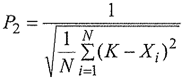


Claims


Priority Applications (4)
| Application Number | Priority Date | Filing Date | Title |
|---|---|---|---|
| DE112005002077.0T DE112005002077B4 (de) | 2004-08-31 | 2005-08-30 | Zustandserfassungsvorrichtung, Zustandserfassungsverfahren, Zustandserfassungsprogramm, Informationsaufzeichnungsmedium dafür sowie Zustandsanzeigevorrichtung, Zustandsanzeigeverfahren, Zustandsanzeigeprogramm und Informationsaufzeichnungsmedium dafür |
| JP2006532732A JP4771334B2 (ja) | 2004-08-31 | 2005-08-30 | 状態検出装置及び状態検出方法並びに状態検出用プログラム及び情報記録媒体、状態表示装置及び状態表示方法並びに状態表示用プログラム及び情報記録媒体 |
| CN2005800290395A CN101010578B (zh) | 2004-08-31 | 2005-08-30 | 状态检测装置、状态检测方法、状态显示装置及状态显示方法 |
| US11/661,103 US7546211B2 (en) | 2004-08-31 | 2005-08-30 | Condition detection apparatus, condition detection method, condition detection program, information recording medium therefor, and condition display apparatus, condition display method, condition display program, information recording medium therefor |
Applications Claiming Priority (4)
| Application Number | Priority Date | Filing Date | Title |
|---|---|---|---|
| JP2004-253390 | 2004-08-31 | ||
| JP2004253390 | 2004-08-31 | ||
| JP2004253389 | 2004-08-31 | ||
| JP2004-253389 | 2004-08-31 |
Publications (1)
| Publication Number | Publication Date |
|---|---|
| WO2006025404A1 true WO2006025404A1 (ja) | 2006-03-09 |
Family
ID=36000054
Family Applications (1)
| Application Number | Title | Priority Date | Filing Date |
|---|---|---|---|
| PCT/JP2005/015792 Ceased WO2006025404A1 (ja) | 2004-08-31 | 2005-08-30 | 状態検出装置及び状態検出方法並びに状態検出用プログラム及び情報記録媒体、状態表示装置及び状態表示方法並びに状態表示用プログラム及び情報記録媒体 |
Country Status (5)
| Country | Link |
|---|---|
| US (1) | US7546211B2 (ja) |
| JP (1) | JP4771334B2 (ja) |
| CN (1) | CN101010578B (ja) |
| DE (1) | DE112005002077B4 (ja) |
| WO (1) | WO2006025404A1 (ja) |
Cited By (3)
| Publication number | Priority date | Publication date | Assignee | Title |
|---|---|---|---|---|
| EP2031386A4 (en) * | 2006-05-24 | 2016-01-27 | Jtekt Corp | ACOUSTIC EMISSION DETECTION AND MONITORING DEVICE |
| WO2018092498A1 (ja) * | 2016-11-21 | 2018-05-24 | Thk株式会社 | 転がり案内装置の状態診断システム |
| JP2023113732A (ja) * | 2021-04-13 | 2023-08-16 | 日本精工株式会社 | リニアガイドの状態監視装置および状態監視方法 |
Families Citing this family (24)
| Publication number | Priority date | Publication date | Assignee | Title |
|---|---|---|---|---|
| JP4430316B2 (ja) * | 2003-02-28 | 2010-03-10 | Thk株式会社 | 状態検出装置及び状態検出方法並びに状態検出用プログラム及び情報記録媒体 |
| EP2401517B1 (en) * | 2009-01-28 | 2018-03-14 | Ab Skf | Lubrication condition monitoring |
| DE102010015208A1 (de) | 2010-04-16 | 2011-10-20 | Schaeffler Technologies Gmbh & Co. Kg | Verfahren zur Überwachung einer Linearführung |
| US8695405B2 (en) * | 2010-09-17 | 2014-04-15 | Bestsens Ag | Bearing, arrangement for determining properties of a lubricant in a bearing and method for determining properties of a lubricant in a bearing |
| DE102010054531A1 (de) | 2010-12-15 | 2012-06-21 | Volkswagen Ag | Verfahren zur Bestimmung eines Zustands eines Verbrennungsmotors eines Fahrzeugs mit weiterem Motor sowie entsprechende Vorrichtung und Fahrzeug |
| JP5940213B2 (ja) * | 2012-05-02 | 2016-06-29 | シーメンス アクチエンゲゼルシヤフトSiemens Aktiengesellschaft | 軸の損傷を監視するための方法 |
| GB2521359A (en) | 2013-12-17 | 2015-06-24 | Skf Ab | Viscosity estimation from demodulated acoustic emission |
| DE102015202130A1 (de) * | 2015-02-06 | 2016-08-11 | Schaeffler Technologies AG & Co. KG | Baukasten für Lager und Lageranordnung |
| US20150159349A1 (en) * | 2015-02-16 | 2015-06-11 | Caterpillar Inc. | Lubricant testing assembly |
| WO2017048788A1 (en) * | 2015-09-14 | 2017-03-23 | Tolomatic, Inc. | Actuator diagnostics and prognostics |
| DE102016105727B4 (de) * | 2016-03-30 | 2025-01-30 | Hiwin Technologies Corp. | Verfahren zum Erfassen einer Vorspannung einer linearen Führung |
| DE102016205575A1 (de) * | 2016-04-05 | 2017-10-05 | Robert Bosch Gmbh | Führungswagen mit Verformungssensor am Laufbahnelement |
| US11373286B2 (en) | 2016-11-07 | 2022-06-28 | Nabtesco Corporation | Status checking device for built-in object, operation checking device and method for checking built-in object |
| JP6952465B2 (ja) * | 2016-12-28 | 2021-10-20 | Thk株式会社 | 管理システム、及び運動案内装置 |
| JP6841558B2 (ja) * | 2017-02-24 | 2021-03-10 | Thk株式会社 | 転がり案内装置の状態診断システム及び状態診断方法 |
| US10837952B2 (en) * | 2017-12-18 | 2020-11-17 | Aktiebolaget Skf | Method and apparatus for detecting a bearing lubrication failure |
| DE102018204648A1 (de) * | 2018-03-27 | 2019-10-02 | Robert Bosch Gmbh | Führung, Sensoranordnung und Verfahren |
| DE102018209700A1 (de) | 2018-06-15 | 2019-12-19 | Skf Motion Technologies Ab | Baueinheit |
| DE102018209703A1 (de) | 2018-06-15 | 2019-12-19 | Skf Motion Technologies Ab | Baueinheit für einen Linearaktuator |
| JP6686124B1 (ja) * | 2018-12-26 | 2020-04-22 | Thk株式会社 | 転がり案内装置のセンサ取付け構造 |
| DE102019203756A1 (de) * | 2019-03-20 | 2020-09-24 | Robert Bosch Gmbh | Verfahren zur Bestimmung einer auf ein Bewegungslager einwirkenden Kraft |
| DE102019219772A1 (de) * | 2019-09-26 | 2021-04-01 | Robert Bosch Gmbh | Sensorsystem, Linearvorrichtung und Verfahren für ein Sensorsystem |
| EP4174726B1 (en) * | 2021-11-02 | 2025-12-10 | Sony Group Corporation | Adapting a detection model |
| JP7398420B2 (ja) * | 2021-11-12 | 2023-12-14 | Thk株式会社 | 監視システム |
Citations (5)
| Publication number | Priority date | Publication date | Assignee | Title |
|---|---|---|---|---|
| JPS55138616A (en) * | 1979-04-16 | 1980-10-29 | Kansai Electric Power Co Inc:The | Bearing fault discriminating device |
| JPS5863832A (ja) * | 1981-10-13 | 1983-04-15 | Sumitomo Metal Ind Ltd | 周期運動体の監視方法 |
| JPH01172621A (ja) * | 1987-12-26 | 1989-07-07 | Tosoh Corp | 転がり軸受けの異常検出方法 |
| JPH05281094A (ja) * | 1992-03-31 | 1993-10-29 | Nkk Corp | 循環式ころがり案内を備えた直動式ガイドの診断方法 およびその装置 |
| JP2004184400A (ja) * | 2002-11-21 | 2004-07-02 | Nsk Ltd | 機械設備の監視システム |
Family Cites Families (12)
| Publication number | Priority date | Publication date | Assignee | Title |
|---|---|---|---|---|
| US3759095A (en) * | 1971-07-16 | 1973-09-18 | Research Technology | Strip detection apparatus |
| JPH0641769B2 (ja) * | 1985-02-20 | 1994-06-01 | 株式会社日立製作所 | 滑り軸受保護装置 |
| GB8826640D0 (en) * | 1988-11-15 | 1988-12-21 | Sensotect Ltd | Apparatus for determining surface roughness of material |
| DD293017A5 (de) | 1990-03-20 | 1991-08-14 | Th Zittau,De | Verfahren zur digitalen verarbeitung von signalkenngroessen |
| US6142026A (en) * | 1994-06-06 | 2000-11-07 | Toyota Jidosha Kabushiki Kaisha | Wheel information estimating apparatus |
| US5508622A (en) * | 1994-12-14 | 1996-04-16 | Gatzlaff; Harold | Coating defect detector system |
| US5739506A (en) * | 1996-08-20 | 1998-04-14 | Ajax Magnethermic Corporation | Coil position adjustment system in induction heating assembly for metal strip |
| CN1246921A (zh) * | 1998-03-16 | 2000-03-08 | 东海旅客铁道株式会社 | 用于铁路主电机的轴承检测装置 |
| CN1123767C (zh) * | 1999-04-15 | 2003-10-08 | 深圳开发科技股份有限公司 | 轴承组件组合测量装置及方法 |
| US7034711B2 (en) | 2001-08-07 | 2006-04-25 | Nsk Ltd. | Wireless sensor, rolling bearing with sensor, management apparatus and monitoring system |
| US7497784B2 (en) * | 2004-11-24 | 2009-03-03 | Water Ride Concepts, Inc. | Rollable carrier ride |
| JP5248052B2 (ja) * | 2006-10-11 | 2013-07-31 | 日東電工株式会社 | 光学フィルムを有するシート状製品の欠点検査装置、その検査データ処理装置、その切断装置及びその製造システム |
-
2005
- 2005-08-30 DE DE112005002077.0T patent/DE112005002077B4/de not_active Expired - Fee Related
- 2005-08-30 CN CN2005800290395A patent/CN101010578B/zh not_active Expired - Fee Related
- 2005-08-30 US US11/661,103 patent/US7546211B2/en not_active Expired - Lifetime
- 2005-08-30 JP JP2006532732A patent/JP4771334B2/ja not_active Expired - Fee Related
- 2005-08-30 WO PCT/JP2005/015792 patent/WO2006025404A1/ja not_active Ceased
Patent Citations (5)
| Publication number | Priority date | Publication date | Assignee | Title |
|---|---|---|---|---|
| JPS55138616A (en) * | 1979-04-16 | 1980-10-29 | Kansai Electric Power Co Inc:The | Bearing fault discriminating device |
| JPS5863832A (ja) * | 1981-10-13 | 1983-04-15 | Sumitomo Metal Ind Ltd | 周期運動体の監視方法 |
| JPH01172621A (ja) * | 1987-12-26 | 1989-07-07 | Tosoh Corp | 転がり軸受けの異常検出方法 |
| JPH05281094A (ja) * | 1992-03-31 | 1993-10-29 | Nkk Corp | 循環式ころがり案内を備えた直動式ガイドの診断方法 およびその装置 |
| JP2004184400A (ja) * | 2002-11-21 | 2004-07-02 | Nsk Ltd | 機械設備の監視システム |
Cited By (6)
| Publication number | Priority date | Publication date | Assignee | Title |
|---|---|---|---|---|
| EP2031386A4 (en) * | 2006-05-24 | 2016-01-27 | Jtekt Corp | ACOUSTIC EMISSION DETECTION AND MONITORING DEVICE |
| WO2018092498A1 (ja) * | 2016-11-21 | 2018-05-24 | Thk株式会社 | 転がり案内装置の状態診断システム |
| JP2018084426A (ja) * | 2016-11-21 | 2018-05-31 | Thk株式会社 | 転がり案内装置の状態診断システム |
| US10712236B2 (en) | 2016-11-21 | 2020-07-14 | Thk Co., Ltd. | Condition diagnosing system for rolling guide device |
| JP2023113732A (ja) * | 2021-04-13 | 2023-08-16 | 日本精工株式会社 | リニアガイドの状態監視装置および状態監視方法 |
| JP7559873B2 (ja) | 2021-04-13 | 2024-10-02 | 日本精工株式会社 | リニアガイドの状態監視装置および状態監視方法 |
Also Published As
| Publication number | Publication date |
|---|---|
| CN101010578A (zh) | 2007-08-01 |
| US7546211B2 (en) | 2009-06-09 |
| JP4771334B2 (ja) | 2011-09-14 |
| JPWO2006025404A1 (ja) | 2008-05-08 |
| CN101010578B (zh) | 2010-09-08 |
| DE112005002077B4 (de) | 2022-06-09 |
| DE112005002077T5 (de) | 2007-07-19 |
| US20080065354A1 (en) | 2008-03-13 |
Similar Documents
| Publication | Publication Date | Title |
|---|---|---|
| JP4771334B2 (ja) | 状態検出装置及び状態検出方法並びに状態検出用プログラム及び情報記録媒体、状態表示装置及び状態表示方法並びに状態表示用プログラム及び情報記録媒体 | |
| JP4430316B2 (ja) | 状態検出装置及び状態検出方法並びに状態検出用プログラム及び情報記録媒体 | |
| US8214160B2 (en) | State detection device, state detection method, state detection program, and information recording medium | |
| US7813906B2 (en) | Method of predicting residual service life for rolling bearings and a device for predicting residual service life for rolling bearings | |
| US10823638B2 (en) | Monitoring method and monitoring apparatus for determining remaining life of a bearing | |
| JP2017219469A (ja) | 状態監視装置及び状態監視方法 | |
| US20050011266A1 (en) | Method and apparatus for vibration sensing and analysis | |
| JP6714806B2 (ja) | 状態監視装置及び状態監視方法 | |
| CN110214236B (zh) | 滚动导向装置的状态诊断系统及状态诊断方法 | |
| WO2018092498A1 (ja) | 転がり案内装置の状態診断システム | |
| JP2005017128A (ja) | 機械設備の状態監視方法及び装置 | |
| CN105445004B (zh) | 设备零部件的振动曲线归一化平均寿命预测办法 | |
| JP5476413B2 (ja) | 回転機械の健全性診断方法 | |
| Behzad et al. | Defect size estimation in rolling element bearings using vibration time waveform | |
| RU2735130C1 (ru) | Способ оценки ресурса подшипника качения | |
| RU2783172C1 (ru) | Система виброакустической диагностики подшипниковых узлов | |
| Jola et al. | A Comparative Analysis of Thermography and Acoustic Emission Testing for Early Failure Detection in Rotating Machinery | |
| Benkedjouh et al. | Bearings Prognostics based on Blind Sources Separation and Robust Correlation Analysis. |
Legal Events
| Date | Code | Title | Description |
|---|---|---|---|
| AK | Designated states |
Kind code of ref document: A1 Designated state(s): AE AG AL AM AT AU AZ BA BB BG BR BW BY BZ CA CH CN CO CR CU CZ DE DK DM DZ EC EE EG ES FI GB GD GE GH GM HR HU ID IL IN IS JP KE KG KM KP KR KZ LC LK LR LS LT LU LV MA MD MG MK MN MW MX MZ NA NG NI NO NZ OM PG PH PL PT RO RU SC SD SE SG SK SL SM SY TJ TM TN TR TT TZ UA UG US UZ VC VN YU ZA ZM ZW |
|
| AL | Designated countries for regional patents |
Kind code of ref document: A1 Designated state(s): BW GH GM KE LS MW MZ NA SD SL SZ TZ UG ZM ZW AM AZ BY KG KZ MD RU TJ TM AT BE BG CH CY CZ DE DK EE ES FI FR GB GR HU IE IS IT LT LU LV MC NL PL PT RO SE SI SK TR BF BJ CF CG CI CM GA GN GQ GW ML MR NE SN TD TG |
|
| 121 | Ep: the epo has been informed by wipo that ep was designated in this application | ||
| WWE | Wipo information: entry into national phase |
Ref document number: 2006532732 Country of ref document: JP |
|
| WWE | Wipo information: entry into national phase |
Ref document number: 11661103 Country of ref document: US |
|
| WWE | Wipo information: entry into national phase |
Ref document number: 200580029039.5 Country of ref document: CN |
|
| WWE | Wipo information: entry into national phase |
Ref document number: 1120050020770 Country of ref document: DE |
|
| RET | De translation (de og part 6b) |
Ref document number: 112005002077 Country of ref document: DE Date of ref document: 20070719 Kind code of ref document: P |
|
| 122 | Ep: pct application non-entry in european phase | ||
| WWP | Wipo information: published in national office |
Ref document number: 11661103 Country of ref document: US |