WO2006004119A1 - Optical recording medium - Google Patents
Optical recording medium Download PDFInfo
- Publication number
- WO2006004119A1 WO2006004119A1 PCT/JP2005/012412 JP2005012412W WO2006004119A1 WO 2006004119 A1 WO2006004119 A1 WO 2006004119A1 JP 2005012412 W JP2005012412 W JP 2005012412W WO 2006004119 A1 WO2006004119 A1 WO 2006004119A1
- Authority
- WO
- WIPO (PCT)
- Prior art keywords
- layer
- transparent resin
- recording
- recording medium
- resin layer
- Prior art date
Links
Classifications
-
- G—PHYSICS
- G11—INFORMATION STORAGE
- G11B—INFORMATION STORAGE BASED ON RELATIVE MOVEMENT BETWEEN RECORD CARRIER AND TRANSDUCER
- G11B7/00—Recording or reproducing by optical means, e.g. recording using a thermal beam of optical radiation by modifying optical properties or the physical structure, reproducing using an optical beam at lower power by sensing optical properties; Record carriers therefor
- G11B7/24—Record carriers characterised by shape, structure or physical properties, or by the selection of the material
- G11B7/241—Record carriers characterised by shape, structure or physical properties, or by the selection of the material characterised by the selection of the material
- G11B7/242—Record carriers characterised by shape, structure or physical properties, or by the selection of the material characterised by the selection of the material of recording layers
- G11B7/244—Record carriers characterised by shape, structure or physical properties, or by the selection of the material characterised by the selection of the material of recording layers comprising organic materials only
- G11B7/246—Record carriers characterised by shape, structure or physical properties, or by the selection of the material characterised by the selection of the material of recording layers comprising organic materials only containing dyes
-
- G—PHYSICS
- G11—INFORMATION STORAGE
- G11B—INFORMATION STORAGE BASED ON RELATIVE MOVEMENT BETWEEN RECORD CARRIER AND TRANSDUCER
- G11B7/00—Recording or reproducing by optical means, e.g. recording using a thermal beam of optical radiation by modifying optical properties or the physical structure, reproducing using an optical beam at lower power by sensing optical properties; Record carriers therefor
- G11B7/24—Record carriers characterised by shape, structure or physical properties, or by the selection of the material
- G11B7/2403—Layers; Shape, structure or physical properties thereof
- G11B7/24035—Recording layers
- G11B7/24038—Multiple laminated recording layers
-
- G—PHYSICS
- G11—INFORMATION STORAGE
- G11B—INFORMATION STORAGE BASED ON RELATIVE MOVEMENT BETWEEN RECORD CARRIER AND TRANSDUCER
- G11B7/00—Recording or reproducing by optical means, e.g. recording using a thermal beam of optical radiation by modifying optical properties or the physical structure, reproducing using an optical beam at lower power by sensing optical properties; Record carriers therefor
- G11B7/24—Record carriers characterised by shape, structure or physical properties, or by the selection of the material
- G11B7/241—Record carriers characterised by shape, structure or physical properties, or by the selection of the material characterised by the selection of the material
- G11B7/242—Record carriers characterised by shape, structure or physical properties, or by the selection of the material characterised by the selection of the material of recording layers
- G11B7/244—Record carriers characterised by shape, structure or physical properties, or by the selection of the material characterised by the selection of the material of recording layers comprising organic materials only
- G11B7/246—Record carriers characterised by shape, structure or physical properties, or by the selection of the material characterised by the selection of the material of recording layers comprising organic materials only containing dyes
- G11B2007/24612—Record carriers characterised by shape, structure or physical properties, or by the selection of the material characterised by the selection of the material of recording layers comprising organic materials only containing dyes two or more dyes in one layer
-
- G—PHYSICS
- G11—INFORMATION STORAGE
- G11B—INFORMATION STORAGE BASED ON RELATIVE MOVEMENT BETWEEN RECORD CARRIER AND TRANSDUCER
- G11B7/00—Recording or reproducing by optical means, e.g. recording using a thermal beam of optical radiation by modifying optical properties or the physical structure, reproducing using an optical beam at lower power by sensing optical properties; Record carriers therefor
- G11B7/24—Record carriers characterised by shape, structure or physical properties, or by the selection of the material
- G11B7/241—Record carriers characterised by shape, structure or physical properties, or by the selection of the material characterised by the selection of the material
- G11B7/252—Record carriers characterised by shape, structure or physical properties, or by the selection of the material characterised by the selection of the material of layers other than recording layers
- G11B7/257—Record carriers characterised by shape, structure or physical properties, or by the selection of the material characterised by the selection of the material of layers other than recording layers of layers having properties involved in recording or reproduction, e.g. optical interference layers or sensitising layers or dielectric layers, which are protecting the recording layers
- G11B2007/25705—Record carriers characterised by shape, structure or physical properties, or by the selection of the material characterised by the selection of the material of layers other than recording layers of layers having properties involved in recording or reproduction, e.g. optical interference layers or sensitising layers or dielectric layers, which are protecting the recording layers consisting essentially of inorganic materials
- G11B2007/25706—Record carriers characterised by shape, structure or physical properties, or by the selection of the material characterised by the selection of the material of layers other than recording layers of layers having properties involved in recording or reproduction, e.g. optical interference layers or sensitising layers or dielectric layers, which are protecting the recording layers consisting essentially of inorganic materials containing transition metal elements (Zn, Fe, Co, Ni, Pt)
-
- G—PHYSICS
- G11—INFORMATION STORAGE
- G11B—INFORMATION STORAGE BASED ON RELATIVE MOVEMENT BETWEEN RECORD CARRIER AND TRANSDUCER
- G11B7/00—Recording or reproducing by optical means, e.g. recording using a thermal beam of optical radiation by modifying optical properties or the physical structure, reproducing using an optical beam at lower power by sensing optical properties; Record carriers therefor
- G11B7/24—Record carriers characterised by shape, structure or physical properties, or by the selection of the material
- G11B7/241—Record carriers characterised by shape, structure or physical properties, or by the selection of the material characterised by the selection of the material
- G11B7/252—Record carriers characterised by shape, structure or physical properties, or by the selection of the material characterised by the selection of the material of layers other than recording layers
- G11B7/257—Record carriers characterised by shape, structure or physical properties, or by the selection of the material characterised by the selection of the material of layers other than recording layers of layers having properties involved in recording or reproduction, e.g. optical interference layers or sensitising layers or dielectric layers, which are protecting the recording layers
- G11B2007/25705—Record carriers characterised by shape, structure or physical properties, or by the selection of the material characterised by the selection of the material of layers other than recording layers of layers having properties involved in recording or reproduction, e.g. optical interference layers or sensitising layers or dielectric layers, which are protecting the recording layers consisting essentially of inorganic materials
- G11B2007/2571—Record carriers characterised by shape, structure or physical properties, or by the selection of the material characterised by the selection of the material of layers other than recording layers of layers having properties involved in recording or reproduction, e.g. optical interference layers or sensitising layers or dielectric layers, which are protecting the recording layers consisting essentially of inorganic materials containing group 14 elements except carbon (Si, Ge, Sn, Pb)
-
- G—PHYSICS
- G11—INFORMATION STORAGE
- G11B—INFORMATION STORAGE BASED ON RELATIVE MOVEMENT BETWEEN RECORD CARRIER AND TRANSDUCER
- G11B7/00—Recording or reproducing by optical means, e.g. recording using a thermal beam of optical radiation by modifying optical properties or the physical structure, reproducing using an optical beam at lower power by sensing optical properties; Record carriers therefor
- G11B7/24—Record carriers characterised by shape, structure or physical properties, or by the selection of the material
- G11B7/241—Record carriers characterised by shape, structure or physical properties, or by the selection of the material characterised by the selection of the material
- G11B7/252—Record carriers characterised by shape, structure or physical properties, or by the selection of the material characterised by the selection of the material of layers other than recording layers
- G11B7/257—Record carriers characterised by shape, structure or physical properties, or by the selection of the material characterised by the selection of the material of layers other than recording layers of layers having properties involved in recording or reproduction, e.g. optical interference layers or sensitising layers or dielectric layers, which are protecting the recording layers
- G11B2007/25705—Record carriers characterised by shape, structure or physical properties, or by the selection of the material characterised by the selection of the material of layers other than recording layers of layers having properties involved in recording or reproduction, e.g. optical interference layers or sensitising layers or dielectric layers, which are protecting the recording layers consisting essentially of inorganic materials
- G11B2007/25713—Record carriers characterised by shape, structure or physical properties, or by the selection of the material characterised by the selection of the material of layers other than recording layers of layers having properties involved in recording or reproduction, e.g. optical interference layers or sensitising layers or dielectric layers, which are protecting the recording layers consisting essentially of inorganic materials containing nitrogen
-
- G—PHYSICS
- G11—INFORMATION STORAGE
- G11B—INFORMATION STORAGE BASED ON RELATIVE MOVEMENT BETWEEN RECORD CARRIER AND TRANSDUCER
- G11B7/00—Recording or reproducing by optical means, e.g. recording using a thermal beam of optical radiation by modifying optical properties or the physical structure, reproducing using an optical beam at lower power by sensing optical properties; Record carriers therefor
- G11B7/24—Record carriers characterised by shape, structure or physical properties, or by the selection of the material
- G11B7/241—Record carriers characterised by shape, structure or physical properties, or by the selection of the material characterised by the selection of the material
- G11B7/252—Record carriers characterised by shape, structure or physical properties, or by the selection of the material characterised by the selection of the material of layers other than recording layers
- G11B7/257—Record carriers characterised by shape, structure or physical properties, or by the selection of the material characterised by the selection of the material of layers other than recording layers of layers having properties involved in recording or reproduction, e.g. optical interference layers or sensitising layers or dielectric layers, which are protecting the recording layers
- G11B2007/25705—Record carriers characterised by shape, structure or physical properties, or by the selection of the material characterised by the selection of the material of layers other than recording layers of layers having properties involved in recording or reproduction, e.g. optical interference layers or sensitising layers or dielectric layers, which are protecting the recording layers consisting essentially of inorganic materials
- G11B2007/25715—Record carriers characterised by shape, structure or physical properties, or by the selection of the material characterised by the selection of the material of layers other than recording layers of layers having properties involved in recording or reproduction, e.g. optical interference layers or sensitising layers or dielectric layers, which are protecting the recording layers consisting essentially of inorganic materials containing oxygen
-
- G—PHYSICS
- G11—INFORMATION STORAGE
- G11B—INFORMATION STORAGE BASED ON RELATIVE MOVEMENT BETWEEN RECORD CARRIER AND TRANSDUCER
- G11B7/00—Recording or reproducing by optical means, e.g. recording using a thermal beam of optical radiation by modifying optical properties or the physical structure, reproducing using an optical beam at lower power by sensing optical properties; Record carriers therefor
- G11B7/24—Record carriers characterised by shape, structure or physical properties, or by the selection of the material
- G11B7/241—Record carriers characterised by shape, structure or physical properties, or by the selection of the material characterised by the selection of the material
- G11B7/252—Record carriers characterised by shape, structure or physical properties, or by the selection of the material characterised by the selection of the material of layers other than recording layers
- G11B7/257—Record carriers characterised by shape, structure or physical properties, or by the selection of the material characterised by the selection of the material of layers other than recording layers of layers having properties involved in recording or reproduction, e.g. optical interference layers or sensitising layers or dielectric layers, which are protecting the recording layers
- G11B2007/25705—Record carriers characterised by shape, structure or physical properties, or by the selection of the material characterised by the selection of the material of layers other than recording layers of layers having properties involved in recording or reproduction, e.g. optical interference layers or sensitising layers or dielectric layers, which are protecting the recording layers consisting essentially of inorganic materials
- G11B2007/25716—Record carriers characterised by shape, structure or physical properties, or by the selection of the material characterised by the selection of the material of layers other than recording layers of layers having properties involved in recording or reproduction, e.g. optical interference layers or sensitising layers or dielectric layers, which are protecting the recording layers consisting essentially of inorganic materials containing sulfur
-
- G—PHYSICS
- G11—INFORMATION STORAGE
- G11B—INFORMATION STORAGE BASED ON RELATIVE MOVEMENT BETWEEN RECORD CARRIER AND TRANSDUCER
- G11B7/00—Recording or reproducing by optical means, e.g. recording using a thermal beam of optical radiation by modifying optical properties or the physical structure, reproducing using an optical beam at lower power by sensing optical properties; Record carriers therefor
- G11B7/24—Record carriers characterised by shape, structure or physical properties, or by the selection of the material
- G11B7/241—Record carriers characterised by shape, structure or physical properties, or by the selection of the material characterised by the selection of the material
- G11B7/252—Record carriers characterised by shape, structure or physical properties, or by the selection of the material characterised by the selection of the material of layers other than recording layers
- G11B7/257—Record carriers characterised by shape, structure or physical properties, or by the selection of the material characterised by the selection of the material of layers other than recording layers of layers having properties involved in recording or reproduction, e.g. optical interference layers or sensitising layers or dielectric layers, which are protecting the recording layers
- G11B2007/25705—Record carriers characterised by shape, structure or physical properties, or by the selection of the material characterised by the selection of the material of layers other than recording layers of layers having properties involved in recording or reproduction, e.g. optical interference layers or sensitising layers or dielectric layers, which are protecting the recording layers consisting essentially of inorganic materials
- G11B2007/25718—Record carriers characterised by shape, structure or physical properties, or by the selection of the material characterised by the selection of the material of layers other than recording layers of layers having properties involved in recording or reproduction, e.g. optical interference layers or sensitising layers or dielectric layers, which are protecting the recording layers consisting essentially of inorganic materials containing halides (F, Cl, Br, l)
-
- G—PHYSICS
- G11—INFORMATION STORAGE
- G11B—INFORMATION STORAGE BASED ON RELATIVE MOVEMENT BETWEEN RECORD CARRIER AND TRANSDUCER
- G11B7/00—Recording or reproducing by optical means, e.g. recording using a thermal beam of optical radiation by modifying optical properties or the physical structure, reproducing using an optical beam at lower power by sensing optical properties; Record carriers therefor
- G11B7/004—Recording, reproducing or erasing methods; Read, write or erase circuits therefor
- G11B7/0045—Recording
- G11B7/00455—Recording involving reflectivity, absorption or colour changes
-
- G—PHYSICS
- G11—INFORMATION STORAGE
- G11B—INFORMATION STORAGE BASED ON RELATIVE MOVEMENT BETWEEN RECORD CARRIER AND TRANSDUCER
- G11B7/00—Recording or reproducing by optical means, e.g. recording using a thermal beam of optical radiation by modifying optical properties or the physical structure, reproducing using an optical beam at lower power by sensing optical properties; Record carriers therefor
- G11B7/24—Record carriers characterised by shape, structure or physical properties, or by the selection of the material
- G11B7/241—Record carriers characterised by shape, structure or physical properties, or by the selection of the material characterised by the selection of the material
- G11B7/242—Record carriers characterised by shape, structure or physical properties, or by the selection of the material characterised by the selection of the material of recording layers
- G11B7/244—Record carriers characterised by shape, structure or physical properties, or by the selection of the material characterised by the selection of the material of recording layers comprising organic materials only
- G11B7/246—Record carriers characterised by shape, structure or physical properties, or by the selection of the material characterised by the selection of the material of recording layers comprising organic materials only containing dyes
- G11B7/2463—Record carriers characterised by shape, structure or physical properties, or by the selection of the material characterised by the selection of the material of recording layers comprising organic materials only containing dyes azulene
-
- G—PHYSICS
- G11—INFORMATION STORAGE
- G11B—INFORMATION STORAGE BASED ON RELATIVE MOVEMENT BETWEEN RECORD CARRIER AND TRANSDUCER
- G11B7/00—Recording or reproducing by optical means, e.g. recording using a thermal beam of optical radiation by modifying optical properties or the physical structure, reproducing using an optical beam at lower power by sensing optical properties; Record carriers therefor
- G11B7/24—Record carriers characterised by shape, structure or physical properties, or by the selection of the material
- G11B7/241—Record carriers characterised by shape, structure or physical properties, or by the selection of the material characterised by the selection of the material
- G11B7/242—Record carriers characterised by shape, structure or physical properties, or by the selection of the material characterised by the selection of the material of recording layers
- G11B7/244—Record carriers characterised by shape, structure or physical properties, or by the selection of the material characterised by the selection of the material of recording layers comprising organic materials only
- G11B7/246—Record carriers characterised by shape, structure or physical properties, or by the selection of the material characterised by the selection of the material of recording layers comprising organic materials only containing dyes
- G11B7/2467—Record carriers characterised by shape, structure or physical properties, or by the selection of the material characterised by the selection of the material of recording layers comprising organic materials only containing dyes azo-dyes
-
- G—PHYSICS
- G11—INFORMATION STORAGE
- G11B—INFORMATION STORAGE BASED ON RELATIVE MOVEMENT BETWEEN RECORD CARRIER AND TRANSDUCER
- G11B7/00—Recording or reproducing by optical means, e.g. recording using a thermal beam of optical radiation by modifying optical properties or the physical structure, reproducing using an optical beam at lower power by sensing optical properties; Record carriers therefor
- G11B7/24—Record carriers characterised by shape, structure or physical properties, or by the selection of the material
- G11B7/241—Record carriers characterised by shape, structure or physical properties, or by the selection of the material characterised by the selection of the material
- G11B7/242—Record carriers characterised by shape, structure or physical properties, or by the selection of the material characterised by the selection of the material of recording layers
- G11B7/244—Record carriers characterised by shape, structure or physical properties, or by the selection of the material characterised by the selection of the material of recording layers comprising organic materials only
- G11B7/246—Record carriers characterised by shape, structure or physical properties, or by the selection of the material characterised by the selection of the material of recording layers comprising organic materials only containing dyes
- G11B7/247—Record carriers characterised by shape, structure or physical properties, or by the selection of the material characterised by the selection of the material of recording layers comprising organic materials only containing dyes methine or polymethine dyes
- G11B7/2472—Record carriers characterised by shape, structure or physical properties, or by the selection of the material characterised by the selection of the material of recording layers comprising organic materials only containing dyes methine or polymethine dyes cyanine
-
- G—PHYSICS
- G11—INFORMATION STORAGE
- G11B—INFORMATION STORAGE BASED ON RELATIVE MOVEMENT BETWEEN RECORD CARRIER AND TRANSDUCER
- G11B7/00—Recording or reproducing by optical means, e.g. recording using a thermal beam of optical radiation by modifying optical properties or the physical structure, reproducing using an optical beam at lower power by sensing optical properties; Record carriers therefor
- G11B7/24—Record carriers characterised by shape, structure or physical properties, or by the selection of the material
- G11B7/241—Record carriers characterised by shape, structure or physical properties, or by the selection of the material characterised by the selection of the material
- G11B7/242—Record carriers characterised by shape, structure or physical properties, or by the selection of the material characterised by the selection of the material of recording layers
- G11B7/244—Record carriers characterised by shape, structure or physical properties, or by the selection of the material characterised by the selection of the material of recording layers comprising organic materials only
- G11B7/246—Record carriers characterised by shape, structure or physical properties, or by the selection of the material characterised by the selection of the material of recording layers comprising organic materials only containing dyes
- G11B7/247—Record carriers characterised by shape, structure or physical properties, or by the selection of the material characterised by the selection of the material of recording layers comprising organic materials only containing dyes methine or polymethine dyes
- G11B7/2475—Record carriers characterised by shape, structure or physical properties, or by the selection of the material characterised by the selection of the material of recording layers comprising organic materials only containing dyes methine or polymethine dyes merocyanine
-
- G—PHYSICS
- G11—INFORMATION STORAGE
- G11B—INFORMATION STORAGE BASED ON RELATIVE MOVEMENT BETWEEN RECORD CARRIER AND TRANSDUCER
- G11B7/00—Recording or reproducing by optical means, e.g. recording using a thermal beam of optical radiation by modifying optical properties or the physical structure, reproducing using an optical beam at lower power by sensing optical properties; Record carriers therefor
- G11B7/24—Record carriers characterised by shape, structure or physical properties, or by the selection of the material
- G11B7/241—Record carriers characterised by shape, structure or physical properties, or by the selection of the material characterised by the selection of the material
- G11B7/242—Record carriers characterised by shape, structure or physical properties, or by the selection of the material characterised by the selection of the material of recording layers
- G11B7/244—Record carriers characterised by shape, structure or physical properties, or by the selection of the material characterised by the selection of the material of recording layers comprising organic materials only
- G11B7/246—Record carriers characterised by shape, structure or physical properties, or by the selection of the material characterised by the selection of the material of recording layers comprising organic materials only containing dyes
- G11B7/248—Record carriers characterised by shape, structure or physical properties, or by the selection of the material characterised by the selection of the material of recording layers comprising organic materials only containing dyes porphines; azaporphines, e.g. phthalocyanines
-
- G—PHYSICS
- G11—INFORMATION STORAGE
- G11B—INFORMATION STORAGE BASED ON RELATIVE MOVEMENT BETWEEN RECORD CARRIER AND TRANSDUCER
- G11B7/00—Recording or reproducing by optical means, e.g. recording using a thermal beam of optical radiation by modifying optical properties or the physical structure, reproducing using an optical beam at lower power by sensing optical properties; Record carriers therefor
- G11B7/24—Record carriers characterised by shape, structure or physical properties, or by the selection of the material
- G11B7/241—Record carriers characterised by shape, structure or physical properties, or by the selection of the material characterised by the selection of the material
- G11B7/242—Record carriers characterised by shape, structure or physical properties, or by the selection of the material characterised by the selection of the material of recording layers
- G11B7/244—Record carriers characterised by shape, structure or physical properties, or by the selection of the material characterised by the selection of the material of recording layers comprising organic materials only
- G11B7/249—Record carriers characterised by shape, structure or physical properties, or by the selection of the material characterised by the selection of the material of recording layers comprising organic materials only containing organometallic compounds
-
- G—PHYSICS
- G11—INFORMATION STORAGE
- G11B—INFORMATION STORAGE BASED ON RELATIVE MOVEMENT BETWEEN RECORD CARRIER AND TRANSDUCER
- G11B7/00—Recording or reproducing by optical means, e.g. recording using a thermal beam of optical radiation by modifying optical properties or the physical structure, reproducing using an optical beam at lower power by sensing optical properties; Record carriers therefor
- G11B7/24—Record carriers characterised by shape, structure or physical properties, or by the selection of the material
- G11B7/241—Record carriers characterised by shape, structure or physical properties, or by the selection of the material characterised by the selection of the material
- G11B7/252—Record carriers characterised by shape, structure or physical properties, or by the selection of the material characterised by the selection of the material of layers other than recording layers
- G11B7/253—Record carriers characterised by shape, structure or physical properties, or by the selection of the material characterised by the selection of the material of layers other than recording layers of substrates
- G11B7/2531—Record carriers characterised by shape, structure or physical properties, or by the selection of the material characterised by the selection of the material of layers other than recording layers of substrates comprising glass
-
- G—PHYSICS
- G11—INFORMATION STORAGE
- G11B—INFORMATION STORAGE BASED ON RELATIVE MOVEMENT BETWEEN RECORD CARRIER AND TRANSDUCER
- G11B7/00—Recording or reproducing by optical means, e.g. recording using a thermal beam of optical radiation by modifying optical properties or the physical structure, reproducing using an optical beam at lower power by sensing optical properties; Record carriers therefor
- G11B7/24—Record carriers characterised by shape, structure or physical properties, or by the selection of the material
- G11B7/241—Record carriers characterised by shape, structure or physical properties, or by the selection of the material characterised by the selection of the material
- G11B7/252—Record carriers characterised by shape, structure or physical properties, or by the selection of the material characterised by the selection of the material of layers other than recording layers
- G11B7/253—Record carriers characterised by shape, structure or physical properties, or by the selection of the material characterised by the selection of the material of layers other than recording layers of substrates
- G11B7/2532—Record carriers characterised by shape, structure or physical properties, or by the selection of the material characterised by the selection of the material of layers other than recording layers of substrates comprising metals
-
- G—PHYSICS
- G11—INFORMATION STORAGE
- G11B—INFORMATION STORAGE BASED ON RELATIVE MOVEMENT BETWEEN RECORD CARRIER AND TRANSDUCER
- G11B7/00—Recording or reproducing by optical means, e.g. recording using a thermal beam of optical radiation by modifying optical properties or the physical structure, reproducing using an optical beam at lower power by sensing optical properties; Record carriers therefor
- G11B7/24—Record carriers characterised by shape, structure or physical properties, or by the selection of the material
- G11B7/241—Record carriers characterised by shape, structure or physical properties, or by the selection of the material characterised by the selection of the material
- G11B7/252—Record carriers characterised by shape, structure or physical properties, or by the selection of the material characterised by the selection of the material of layers other than recording layers
- G11B7/253—Record carriers characterised by shape, structure or physical properties, or by the selection of the material characterised by the selection of the material of layers other than recording layers of substrates
- G11B7/2533—Record carriers characterised by shape, structure or physical properties, or by the selection of the material characterised by the selection of the material of layers other than recording layers of substrates comprising resins
- G11B7/2534—Record carriers characterised by shape, structure or physical properties, or by the selection of the material characterised by the selection of the material of layers other than recording layers of substrates comprising resins polycarbonates [PC]
-
- G—PHYSICS
- G11—INFORMATION STORAGE
- G11B—INFORMATION STORAGE BASED ON RELATIVE MOVEMENT BETWEEN RECORD CARRIER AND TRANSDUCER
- G11B7/00—Recording or reproducing by optical means, e.g. recording using a thermal beam of optical radiation by modifying optical properties or the physical structure, reproducing using an optical beam at lower power by sensing optical properties; Record carriers therefor
- G11B7/24—Record carriers characterised by shape, structure or physical properties, or by the selection of the material
- G11B7/241—Record carriers characterised by shape, structure or physical properties, or by the selection of the material characterised by the selection of the material
- G11B7/252—Record carriers characterised by shape, structure or physical properties, or by the selection of the material characterised by the selection of the material of layers other than recording layers
- G11B7/253—Record carriers characterised by shape, structure or physical properties, or by the selection of the material characterised by the selection of the material of layers other than recording layers of substrates
- G11B7/2533—Record carriers characterised by shape, structure or physical properties, or by the selection of the material characterised by the selection of the material of layers other than recording layers of substrates comprising resins
- G11B7/2535—Record carriers characterised by shape, structure or physical properties, or by the selection of the material characterised by the selection of the material of layers other than recording layers of substrates comprising resins polyesters, e.g. PET, PETG or PEN
-
- G—PHYSICS
- G11—INFORMATION STORAGE
- G11B—INFORMATION STORAGE BASED ON RELATIVE MOVEMENT BETWEEN RECORD CARRIER AND TRANSDUCER
- G11B7/00—Recording or reproducing by optical means, e.g. recording using a thermal beam of optical radiation by modifying optical properties or the physical structure, reproducing using an optical beam at lower power by sensing optical properties; Record carriers therefor
- G11B7/24—Record carriers characterised by shape, structure or physical properties, or by the selection of the material
- G11B7/241—Record carriers characterised by shape, structure or physical properties, or by the selection of the material characterised by the selection of the material
- G11B7/252—Record carriers characterised by shape, structure or physical properties, or by the selection of the material characterised by the selection of the material of layers other than recording layers
- G11B7/253—Record carriers characterised by shape, structure or physical properties, or by the selection of the material characterised by the selection of the material of layers other than recording layers of substrates
- G11B7/2533—Record carriers characterised by shape, structure or physical properties, or by the selection of the material characterised by the selection of the material of layers other than recording layers of substrates comprising resins
- G11B7/2536—Record carriers characterised by shape, structure or physical properties, or by the selection of the material characterised by the selection of the material of layers other than recording layers of substrates comprising resins polystyrene [PS]
-
- G—PHYSICS
- G11—INFORMATION STORAGE
- G11B—INFORMATION STORAGE BASED ON RELATIVE MOVEMENT BETWEEN RECORD CARRIER AND TRANSDUCER
- G11B7/00—Recording or reproducing by optical means, e.g. recording using a thermal beam of optical radiation by modifying optical properties or the physical structure, reproducing using an optical beam at lower power by sensing optical properties; Record carriers therefor
- G11B7/24—Record carriers characterised by shape, structure or physical properties, or by the selection of the material
- G11B7/241—Record carriers characterised by shape, structure or physical properties, or by the selection of the material characterised by the selection of the material
- G11B7/252—Record carriers characterised by shape, structure or physical properties, or by the selection of the material characterised by the selection of the material of layers other than recording layers
- G11B7/256—Record carriers characterised by shape, structure or physical properties, or by the selection of the material characterised by the selection of the material of layers other than recording layers of layers improving adhesion between layers
-
- G—PHYSICS
- G11—INFORMATION STORAGE
- G11B—INFORMATION STORAGE BASED ON RELATIVE MOVEMENT BETWEEN RECORD CARRIER AND TRANSDUCER
- G11B7/00—Recording or reproducing by optical means, e.g. recording using a thermal beam of optical radiation by modifying optical properties or the physical structure, reproducing using an optical beam at lower power by sensing optical properties; Record carriers therefor
- G11B7/24—Record carriers characterised by shape, structure or physical properties, or by the selection of the material
- G11B7/241—Record carriers characterised by shape, structure or physical properties, or by the selection of the material characterised by the selection of the material
- G11B7/252—Record carriers characterised by shape, structure or physical properties, or by the selection of the material characterised by the selection of the material of layers other than recording layers
- G11B7/257—Record carriers characterised by shape, structure or physical properties, or by the selection of the material characterised by the selection of the material of layers other than recording layers of layers having properties involved in recording or reproduction, e.g. optical interference layers or sensitising layers or dielectric layers, which are protecting the recording layers
- G11B7/2578—Record carriers characterised by shape, structure or physical properties, or by the selection of the material characterised by the selection of the material of layers other than recording layers of layers having properties involved in recording or reproduction, e.g. optical interference layers or sensitising layers or dielectric layers, which are protecting the recording layers consisting essentially of inorganic materials
-
- G—PHYSICS
- G11—INFORMATION STORAGE
- G11B—INFORMATION STORAGE BASED ON RELATIVE MOVEMENT BETWEEN RECORD CARRIER AND TRANSDUCER
- G11B7/00—Recording or reproducing by optical means, e.g. recording using a thermal beam of optical radiation by modifying optical properties or the physical structure, reproducing using an optical beam at lower power by sensing optical properties; Record carriers therefor
- G11B7/24—Record carriers characterised by shape, structure or physical properties, or by the selection of the material
- G11B7/241—Record carriers characterised by shape, structure or physical properties, or by the selection of the material characterised by the selection of the material
- G11B7/252—Record carriers characterised by shape, structure or physical properties, or by the selection of the material characterised by the selection of the material of layers other than recording layers
- G11B7/258—Record carriers characterised by shape, structure or physical properties, or by the selection of the material characterised by the selection of the material of layers other than recording layers of reflective layers
- G11B7/259—Record carriers characterised by shape, structure or physical properties, or by the selection of the material characterised by the selection of the material of layers other than recording layers of reflective layers based on silver
-
- G—PHYSICS
- G11—INFORMATION STORAGE
- G11B—INFORMATION STORAGE BASED ON RELATIVE MOVEMENT BETWEEN RECORD CARRIER AND TRANSDUCER
- G11B7/00—Recording or reproducing by optical means, e.g. recording using a thermal beam of optical radiation by modifying optical properties or the physical structure, reproducing using an optical beam at lower power by sensing optical properties; Record carriers therefor
- G11B7/24—Record carriers characterised by shape, structure or physical properties, or by the selection of the material
- G11B7/241—Record carriers characterised by shape, structure or physical properties, or by the selection of the material characterised by the selection of the material
- G11B7/252—Record carriers characterised by shape, structure or physical properties, or by the selection of the material characterised by the selection of the material of layers other than recording layers
- G11B7/258—Record carriers characterised by shape, structure or physical properties, or by the selection of the material characterised by the selection of the material of layers other than recording layers of reflective layers
- G11B7/2595—Record carriers characterised by shape, structure or physical properties, or by the selection of the material characterised by the selection of the material of layers other than recording layers of reflective layers based on gold
-
- Y—GENERAL TAGGING OF NEW TECHNOLOGICAL DEVELOPMENTS; GENERAL TAGGING OF CROSS-SECTIONAL TECHNOLOGIES SPANNING OVER SEVERAL SECTIONS OF THE IPC; TECHNICAL SUBJECTS COVERED BY FORMER USPC CROSS-REFERENCE ART COLLECTIONS [XRACs] AND DIGESTS
- Y10—TECHNICAL SUBJECTS COVERED BY FORMER USPC
- Y10T—TECHNICAL SUBJECTS COVERED BY FORMER US CLASSIFICATION
- Y10T428/00—Stock material or miscellaneous articles
- Y10T428/21—Circular sheet or circular blank
Definitions
- the present invention relates to an optical recording medium, and more particularly to an optical recording medium capable of high-speed recording and having good recording reproduction characteristics.
- optical recording media such as CD-R, CD-RW, and MO can store a large amount of information, and there are also media that can be easily accessed at random, such as DVD-RAM. It has been developed and widely recognized as an external storage device in information processing devices such as computers.
- a typical CD-R having an organic dye-containing recording layer has a dye recording layer and a reflective layer in this order on a transparent disk substrate, and a laminate having a protective layer covering these recording layers and the reflective layer.
- the structure is such that recording and reproduction are performed with a laser beam through the substrate.
- a multilayer optical recording medium in which a plurality of recording layers are provided on one medium has been developed.
- a two-layer type optical recording medium having two dye recording layers on an intermediate layer made of an ultraviolet curable resin is reported (see Patent Document 1).
- Such a two-layer optical recording medium is a photo-curable resin layer formed by forming two disk substrates on which a 2P (Photo Polymerization) method using a transparent stamper and a recording layer and a reflective layer are laminated.
- the method of sticking through is known.
- a photocurable resin material is applied on a first substrate provided with a first recording layer and a first reflective layer, and a transparent stamper having an uneven shape is formed on the coated surface.
- the photocurable resin raw material is cured, and then the transparent stamper is peeled off to transfer the irregularities to the surface of the photocurable resin, and the second recording layer and the second recording layer are further formed on the irregular surface.
- the reflective layer is sequentially formed, and the second substrate is finally bonded.
- recording / reproducing light incident from the first substrate side is used to record / reproduce optical information.
- Patent Document 1 Japanese Patent Application Laid-Open No. 2000-311384 (see columns (0008) to (0019))
- an optical recording medium provided with a recording layer containing an organic dye has a problem that the occurrence of crosstalk in high-speed recording applications is further suppressed.
- the dye that has absorbed the condensed recording laser beam is usually decomposed, the thickness of the portion decreases, the pressure increases, and the recording layer is exposed to a high temperature.
- the periphery is deformed to form a recording part.
- the deformed recording portion expands to the adjacent track portion, and when recording is performed on a plurality of tracks, the crosstalk tends to increase, resulting in a phenomenon that good jitter is not obtained.
- MT (%) the jitter when information is recorded on a plurality of tracks and the signals recorded on the adjacent tracks are reproduced.
- ST (%) the jitter obtained by reproducing the portion recorded on only one track when there is no recording on the adjacent track.
- MT (%) includes the effects of crosstalk, while ST (%) does not include the effects of crosstalk.
- the recording pulse is shortened in the case of high-speed recording, it is necessary to decompose the dye using a recording laser beam having a higher performance than in the case of low-speed recording.
- the recording layer is exposed to a higher temperature than in the case of low speed recording, the increase in crosstalk tends to be remarkable.
- Such crosstalk occurs particularly in the second layer on the back side from the incident surface of the recording / reproducing light in the two-layer optical recording medium formed by the method of adhering two disc substrates. It is prominent in the eye recording layer.
- the method of attaching two disc substrates The second recording layer of the two-layer type optical recording medium formed by the above is provided on a disc substrate having a reverse laminate in which a reflective layer and a recording layer are laminated on a substrate.
- a reverse laminate when optical information is recorded in the inter-groove portion of the substrate, it is necessary to increase the thickness of the recording layer in the inter-groove portion in order to ensure the recording modulation degree.
- the adjacent track of the recording portion is a groove portion of the substrate
- the recording layer film thickness tends to be thicker than the portion between the grooves. For this reason, as the recording layer film thickness in the groove portion increases, the recording mark spreads laterally, and crosstalk tends to increase. Such a difference in recording film thickness between the groove and the groove is likely to occur when an organic dye solution is applied.
- the second substrate provided on the back side of the incident surface force of recording / reproducing light in the two-layer optical recording medium has a conventional guide groove depth in order to ensure the reflectance of the recording / reproducing light. It is set shallower than. For this reason, the physical barrier effect of the guide groove is reduced, and excessive deformation occurs due to flow deformation of the substrate grease during recording, and crosstalk is likely to increase.
- the present invention has been made to solve such a problem.
- an object of the present invention is to provide an optical recording medium capable of obtaining good recording / reproducing characteristics in high-speed recording applications.
- the product (EX t) of the elastic modulus (E) and thickness (t) of the transparent resin layer in contact with the reverse laminate is specified. Adjust to the range! /
- the substrate comprises a reverse laminate having a reflective layer and a recording layer in this order, and a transparent resin layer provided on the recording layer side of the reverse laminate,
- An optical recording medium is provided in which the product 1 of the thickness (t) and the inertia ratio at 25 ⁇ 5 is equal to or higher than 2.0 ⁇ 10 4 ⁇ & ⁇ / ⁇ ⁇ .
- the product (E x t) of the thickness (t) of the transparent resin layer and the elastic modulus ( ⁇ ) at 25 ⁇ 5 ° C is 30
- the elastic modulus ( ⁇ ⁇ ⁇ ⁇ ) at 25 ⁇ 5 ° C of the resin constituting the transparent resin layer is 3.0 X 10 3 M
- the recording layer constituting the reverse laminate is
- the organic dye is preferably contained.
- 2 as shown in Figure 1 below.
- cross-talk is reduced when recording is performed on a reverse laminate comprising a substrate, a reflective layer, and a recording layer, and MT (%) is improved.
- MT MT (%) is improved.
- other layers may be provided as appropriate between the substrate and the reflective layer, or between the reflective layer and the recording layer.
- the optical recording medium to which the present invention is applied it is preferable to further provide an intermediate layer between the recording layer constituting the reverse laminate and the transparent resin layer in contact therewith.
- the intermediate layer it is possible to prevent the component exuding from the transparent resin layer from contaminating or dissolving the recording layer in contact with the transparent resin layer.
- the second reflective layer, the second recording layer, and the transparent substrate on the opposite side of the transparent resin layer in contact with the reverse laminate to the reverse laminate side can be developed in a multilayer optical recording medium.
- the present invention relates to a recording layer on which optical information is recorded and reproduced by light irradiation, a transparent resin layer provided on the light incident surface side of the recording layer, and a light incident surface of the recording layer.
- the product (EX t) of the thickness (t) of the transparent resin layer and the elastic modulus (E) at 25 ⁇ 5 ° C is 2.0 ⁇ 10 4 ⁇ & ⁇ / ⁇ ⁇ or more can be grasped as an optical recording medium. That is, for an optical recording medium having a configuration in which a transparent resin layer having a specific value of Xt) is provided on the light incident surface side of the recording layer having a reflective layer on the side opposite to the light incident surface.
- Such an improvement in performance is not limited to the film surface incident type optical recording medium, but is remarkable in the recording layer provided on the back side from the light incident surface in the multilayer type optical recording medium.
- the transparent resin layer is preferably made of a transparent resin having a glass transition temperature of 150 ° C. or higher. It is considered that by forming a transparent resin layer using such a transparent resin, the hardness of the transparent resin layer is increased and jitter is improved.
- an optical recording medium having a substrate, a reflective layer, a recording layer, and a transparent resin layer in this order, and the reflective layer is mainly composed of silver (Ag).
- An optical recording medium comprising a metal and having a film thickness of 30 nm to 80 nm is provided.
- the optical recording medium to which the present invention is applied has a reverse laminated structure having a substrate, a reflective layer, a recording layer, and a transparent resin layer in this order, and is a reflective layer containing a metal mainly composed of silver. film
- the thickness is 30 nm or more and 80 nm or less, a part of the light beam incident on the reflection layer from the recording layer side can be transmitted. In this case, energy for recording information on the recording layer is diffused.
- the recording mark protrudes to an adjacent track (crosstalk). ) Phenomenon is suppressed, and as a result, jitter can be improved.
- the reflective layer contains 50% or more of Ag. Further, Ag is a main component, and 0.1 atom of one or more elements of Ti, Bi, Zn, Cu, Pd and rare earth metal is contained. % To 15 atomic% is preferable.
- an optical recording medium capable of obtaining good recording / reproducing characteristics in high-speed recording applications can be obtained.
- FIG. 1 is a diagram for explaining a first embodiment of an optical recording medium to which this embodiment is applied (in this example, a single-sided incident dual-layer DVD).
- Figure 1 shows a disk substrate (reverse laminate 11) in which a reflective layer and a recording layer are laminated on a transparent substrate, and a disk substrate (normal laminate 12) in which a recording layer and a reflective layer are sequentially laminated on a transparent substrate.
- a two-layer optical recording medium 100 is shown.
- an optical recording medium 100 includes a disc-shaped light-transmitting substrate (1) 101 in which grooves and lands or pits are formed as an inverse laminate 11, and this substrate ( 1) A reflection layer (1) 102 provided on the incident surface side of the laser beam 110 of 101, a recording layer (1) 103 containing a dye, and an intermediate layer 104. Further, as the regular laminate 12, a disk-shaped light-transmitting substrate (2) 109 in which grooves and lands or prepits are formed, and a recording layer (2) containing a dye provided on the substrate (2) 109 108, a translucent reflective layer (2) 107 that distributes the power of the incident laser beam 110 from the substrate (2) 109 side, and a protective coating layer 106 provided on the reflective layer (2) 107 And having.
- the reverse laminate 11 and the regular laminate 12 are laminated via the transparent resin layer 105 so that the intermediate layer 104 and the protective coat layer 106 are opposed to each other, and the two-layer type optical recording medium 100 is formed. It is composed.
- the recording layer (1) 103 and the recording layer (2) 108 perform recording / reproduction of optical information by the laser beam 110 on which the side force of the substrate (2) 109 of the positive laminate 12 is also incident.
- the reverse laminate 11 includes a substrate (1) 101, a reflective layer (1) 102, a recording layer (1) 103, and an intermediate layer 104 (hereinafter referred to as “laminated”) on the substrate (1) 101. , Sometimes referred to as the L1 layer).
- the material constituting the substrate (1) 101 is desirably optically transparent and has excellent optical properties such as a low birefringence. In addition, it is desirable to have excellent moldability such as easy injection molding. Furthermore, it is desirable that the hygroscopicity is small. Furthermore, it is desirable to provide shape stability so that the optical recording medium 100 has a certain degree of rigidity.
- a material is not particularly limited. For example, acrylic resin, methacrylic resin, polycarbonate resin, polyolefin resin (especially amorphous polyolefin), polyester resin, polystyrene resin. , Epoxy resin, glass and the like.
- substrates such as glass
- polycarbonate is preferable in terms of high productivity such as optical characteristics and moldability, cost, low hygroscopicity, shape stability and the like.
- Amorphous polyolefin is preferred from the standpoints of chemical resistance and low hygroscopicity.
- a glass substrate is preferable from the viewpoint of high-speed response.
- the substrate (1) 101 does not necessarily need to be light transmissive, it can be provided with a backing having an appropriate material strength in order to increase mechanical stability and increase rigidity.
- a backing having an appropriate material strength in order to increase mechanical stability and increase rigidity.
- A1 alloy substrates such as Al—Mg alloys containing A1 as the main component
- Mg alloy substrates such as Mg—Zn alloys containing Mg as the main component
- a substrate or a combination thereof may be mentioned.
- the groove depth of the guide groove portion of the substrate (1) 101 constituting the reverse laminate 11 is usually ⁇ or more, preferably 2 ⁇ 00 or more, more preferably, based on the recording / reproducing wavelength. 3 ⁇ ⁇ 0 0 or more, provided that ⁇ 6 or less is preferable.
- the groove depth of the substrate (1) 101 is usually 6.6 nm or more, preferably 13 nm or more, more preferably 20 nm or more. It is.
- the upper limit of the groove depth of the substrate (1) 101 is preferably llOnm or less.
- the light quantity and the reflected light quantity of the laser light 110 incident on the recording layer (1) 103 via the substrate (2) 109 and the transparent resin layer 105 are Since the recording layer (2) 108 and the reflection layer (2) 107 are attenuated and the reflectance is lowered, the upper limit of the preferable groove depth is 7 ⁇ or less.
- the groove depth of the substrate (1) 101 is preferably 46.2 nm or less. More preferably, it is 6 ⁇ 100 or less.
- the groove width of the substrate (1) 101 in the reverse laminated body 11 is usually TZ10 or more, preferably 2TZ10 or more, more preferably 3TZ10 or more, where T is the track pitch. However, it is usually 8TZ10 or less, preferably 7TZ10 or less, more preferably 6TZ10 or less. If the groove width of substrate (1) 101 is within this range, tracking can be performed satisfactorily and sufficient reflectance can be obtained. For example, when the track pitch is 740 nm, the groove width of the substrate (1) 101 is usually 74 nm or more, preferably 148 nm or more, and more preferably 222 nm or more.
- the upper limit is usually 592 nm or less, more preferably 518 nm or less, and still more preferably 444 nm or less.
- the substrate (1) 101 is preferably thick to some extent.
- the thickness of the substrate (1) 101 is usually preferably 0.3 mm or more. However, it is 3mm or less, preferably 1.5mm or less.
- the material constituting the reflective layer (1) 102 of the reverse laminate 11 is not particularly limited.
- Metals and metalloids can be used alone or as an alloy.
- Au, Al, and Ag are preferred.
- a metal material containing 50% or more of Ag is preferred because of its low cost and high reflectance.
- a group force consisting mainly of Ag and made of Ti, Zn, Cu, Pd, Au and rare earth metals It is preferable to contain at least one element selected from 0.1 atomic% to 15 atomic%.
- the content of each element may be 0.1 to 15 atomic%, but the total content thereof The amount is preferably from 0.1 atomic% to 15 atomic%.
- the alloy composition contains Ag as a main component, and contains 0.1 atomic% to 15 atomic% of at least one element selected from the group force consisting of Ti, Bi, Zn, Cu, Pd, and Au. If necessary, it contains at least one rare earth element in the range of 0.1 atomic% to 15 atomic%. Among rare earth metals, neodymium is particularly preferable. Specifically, AgPdCu, AgCuAu, AgCu AuNd, AgCuNd, AgBi, AgBiNd, and the like. The composition ratio of the alloy used in the present embodiment is in the above-mentioned range.
- Ag as the main component means that the Ag force in the alloy composition is usually 50% or more, preferably 70% or more, more preferably 80% or more. It is also possible to use pure Ag.
- the reflective layer (1) 102 a layer having only Au is suitable because it has small crystal grains and excellent corrosion resistance. It is also possible to use a layer comprising S as the reflective layer (1) 102. Further, a multilayer film can be formed by alternately stacking a low refractive index thin film and a high refractive index thin film using a material other than metal, and can be used as a reflective layer.
- Examples of the method for forming the reflective layer (1) 102 include sputtering, ion plating, chemical vapor deposition, and vacuum vapor deposition.
- the reflective layer (1) 102 in the reverse laminate 11 has high reflectivity and high durability.
- the thickness of the reflective layer (1) 102 is usually 30 nm or more, preferably 40 nm or more, more preferably 50 nm or more.
- it is usually 400 nm or less, preferably 300 nm or less.
- the reflective layer (1) 102 of the reverse laminate 11 includes a metal whose main component is silver
- the reflective layer (1) 102 The film thickness is more preferably in the range of 30 ⁇ m to 80nm.
- the film thickness of the reflective layer (1) 102 containing silver as a main component is in the range of 30 nm to 80 nm, the decrease in the reflectance of the reflective layer (1) 102 and the increase in the transmittance are balanced to provide energy. Diffusion occurs, resulting in a cross Tend to be improved.
- FIG. 5 is a diagram for explaining the relationship between the thickness of the reflective layer and the transmittance (T), and the thickness of the reflective layer and the reflectance (R).
- Figure 5 (a) shows the relationship between the thickness of the reflective layer and the transmittance (T), and Fig.
- the transmittance (T) increases when the thickness of the reflective layer is less than about 80 nm, and the transmittance (T) exceeds 5% when the thickness is less than 30 nm.
- the reflectance (R) decreases when the thickness of the reflective layer is thinner than around 80 nm, and the reflectance (R) is less than 85% when the thickness is thinner than 30 nm.
- the reflective layer (1) 102 By forming the reflective layer (1) 102 to be thinner than the conventional one, the reflective layer (1) 102 tends to cover (trace) the shape of the groove of the substrate more strictly. Therefore, even when the track pitch is narrowed, the groove and the inter-groove portion are clearly separated, so that crosstalk may be reduced.
- the film thickness of the recording layer (1) 103 is preferably 30 nm or more, more preferably 40 nm or more.
- the thickness of the reflective layer containing a metal whose main component is silver is lOOnm or more. In this case, almost no energy diffusion occurs because the transmittance (T) is low. Therefore, the film thickness of the recording layer (1) 103 is preferably 80 nm or less.
- the reflective layer (1) 102 is formed with a film thickness thinner than the usual lOOnm, The time can be shortened and the temperature rise of the substrate (1) 101 is reduced during sputtering. This mitigates the spattering of the sputtered atoms, potentially creating a reflective layer (1) 102 with small particle size, good quality and low surface roughness, and improved cost performance. Is done.
- the recording layer (1) 103 in the reverse laminate 11 usually contains a dye having the same sensitivity as that of a recording layer used for a single-sided recording medium such as CD-R, DVD-R, DV D + R, etc. .
- a dye having a maximum absorption wavelength ⁇ max in the visible light to near infrared region of about 350 nm to 900 nm and suitable for recording with a blue to near microwave laser is preferable.
- a dye suitable for recording by a so-called blue laser or the like having a wavelength of 660 nm, 680 nm, or a wavelength of 410 nm or 515 ⁇ m is more preferable. It is also possible to use a phase change material.
- the dye used in the recording layer (1) 103 is not particularly limited, but an organic dye material is usually used.
- organic dye materials include macrocyclic azanulene dyes (phthalocyanine dyes, naphthalocyanine dyes, porphyrin dyes, etc.), pyromethene dyes, polymethine dyes (such as cyanine dyes, merocyanine dyes, and sillilium dyes), anthraquinone dyes.
- azurenium dyes metal-containing azo dyes, metal-containing indoor-phosphorus dyes, and the like.
- metal-containing azo dyes are preferable because they are excellent in recording sensitivity, durability and light resistance. These dyes may be used alone or in combination.
- the recording layer (1) 103 includes a transition metal chelate compound (eg, acetyl acetyltonate chelate, bisulfate) as a singlet oxygen quencher in order to improve the stability and light resistance of the recording layer.
- a recording sensitivity improver such as a metal compound may be included for improving the recording sensitivity, such as sugar dithiol, salicylaldehyde oxime, bisdithio oc-diketone, etc.).
- the metal compound means a compound in which a metal such as a transition metal is contained in the compound in the form of atoms, ions, clusters, etc., for example, an ethylenediamine complex, an azomethine compound, etc.
- a metal such as a transition metal
- it does not specifically limit as a metal atom, It is preferable that it is a transition metal.
- the recording layer (1) 103 can be used in combination with a binder, a leveling agent, an antifoaming agent, and the like, if necessary.
- binders include polybutyl alcohol, polyvinyl pyrrolidone, nitrocellulose, cellulose acetate, ketone series resin, acrylic series resin, polystyrene series resin, urethane series resin, polyvinyl butyral, polycarbonate, and polyolefin. Can be mentioned.
- the film-forming method of the recording layer (1) 103 is not particularly limited, but is generally performed by a vacuum evaporation method, a sputtering method, a doctor blade method, a casting method, a spin coating method, an immersion method, or the like.
- a wet film formation method such as a spin coating method is preferable.
- the vacuum evaporation method is preferable from the viewpoint that a uniform recording layer can be obtained.
- the spin speed is preferably 10 rpm and 15000 rpm, and then heat treatment is generally performed to remove the solvent.
- the coating solvent for forming the recording layer by a coating method such as a doctor blade method, a casting method, a spin coating method, or a dipping method is not particularly limited as long as it is a solvent that does not attack the substrate.
- ketone alcohol solvents such as diaceton alcohol and 3-hydroxy-3-methyl-2-butanone
- cellosolv solvents such as methyl solvate and cetyl sorb
- chain hydrocarbon solvents such as n-xane and n-otatan
- Cyclic hydrocarbon solvents such as cyclohexane, methylcyclohexane, ethylcyclohexane, dimethylcyclohexane, n-butylcyclohexane, tert-butylcyclohexane, cyclooctane; tetrafluoroprono-V
- perfluoroalkyl alcohol solvents such as kutafluoropentanol and hexafluorobutanol
- hydroxycarboxylic acid ester solvents such as methyl lactate, ethyl lactate, and methyl 2-hydroxyisobutyrate.
- the heat treatment for removing these solvents removes the solvents and uses simple equipment. Is usually performed at a temperature slightly lower than the boiling point of the solvent used.
- the heat treatment method is not particularly limited.
- a film containing a dye-containing solution is formed on the substrate (1) 101 to form the recording layer (1) 103, and then a predetermined temperature is applied. And a predetermined time (usually 5 minutes or more, preferably 10 minutes or more, but usually within 30 minutes, preferably within 20 minutes).
- a method of heating the substrate (1) 101 by irradiating infrared rays or far infrared rays for a short time for example, 5 seconds to 5 minutes.
- an organic dye and, if necessary, recording layer components such as various additives are put in a crucible installed in a vacuum vessel, and the inside of the vacuum vessel is filled with an appropriate vacuum pump. After evacuating to about 10 2 to 10 _5 Pa, the crucible is heated to evaporate the recording layer components and deposited on the substrate placed facing the crucible.
- the thickness of the recording layer (1) 103 of the reverse laminate 11 is usually 50 nm or more, preferably 60 nm or more, but is usually 150 nm or less, preferably lOO nm or less.
- the thickness of the recording layer (1) 103 is within this range, it is possible to suppress a decrease in sensitivity while ensuring a sufficient recording signal amplitude. Also, if the recording layer (1) 103 is excessively thick, the sensitivity may decrease.
- the intermediate layer 104 is provided in the reverse laminated body 11 as necessary.
- the intermediate layer 104 is formed between the recording layer (1) 103 and the transparent resin layer 105 in order to prevent components from the transparent resin layer 105 from contaminating or dissolving the recording layer (1) 103.
- the thickness of the intermediate layer 104 is usually 1 nm or more, preferably 2 nm or more. If the thickness of the intermediate layer 104 falls within this range, the components that exude from the transparent resin layer 105 can be effectively suppressed. However, the thickness of the intermediate layer 104 is 2000 nm or less, more preferably 500 nm or less. If the thickness of the intermediate layer 104 is within this range, it is possible to prevent a decrease in light transmittance.
- the intermediate layer 104 is a layer made of an inorganic material, it may take time to form a film. Therefore, in order to suppress a decrease in productivity and increase the film stress within a favorable range. 200 nm or less is preferable. In particular, when a metal is used for the intermediate layer 104, the light transmittance is excessive.
- Examples of the material constituting the intermediate layer 104 include dielectrics such as a metal thin film, silicon oxide, silicon nitride, MgF, and SnO ZnS-SnO.
- the substrate (1) 101 and the recording layer (1) 103 between the substrate (2) 109 and the recording layer (2) 108, and between the recording layer (2) 108 and the reflective layer (2) 107.
- layers made of the same material as the intermediate layer 104 may be provided.
- the transparent resin layer 105 in the two-layer type optical recording medium 100 to which the present embodiment is applied has a light transmitting property such that the laser beam 110 incident also on the substrate (2) 109 side force reaches the recording layer (1) 103. Constructed from a temporary material.
- the product (EX) of the elastic modulus (E) (unit: MPa) of the transparent resin layer 105 and the thickness (t) (unit: m) of the transparent resin layer 105 t) (Unit: MPa '/ zm) Force
- the recording layer of the reverse laminate 11 (1) In the optical information recording of 103, it is adjacent to the track part and excessive deformation Can be suppressed.
- transparent of the transparent resin layer 105 means t ⁇ without having a structure for scattering the laser light 110 incident on the optical recording medium 100.
- scattering refers to scattering that has a great influence on the recording / reproducing characteristics of the optical recording medium 100.
- the elastic modulus of the transparent resin layer 105 (unit: MPa, measured at a temperature of 25 ⁇ 5 ° C) and transparent.
- the product (EXt) (unit: MPa '/ zm) of the thickness (t) (unit: / zm) of the resin layer 105 is 2.0X10 4 MPa./zm or more, preferably 2.5X10 4 MPa' or more More preferably 4.0X10 4 MPa '/ zm or more, more preferably 5.0 ⁇ 10 4 ⁇ & ⁇ / ⁇ or more, particularly preferably 7.0X10 4 MPa- ⁇ m or more, and particularly preferably 9.0X10 4 MPa- ⁇ m.
- the upper limit of (wm) is usually 30. OX 10 4 MPa-, um or less, preferably ⁇ or 21.0 ⁇ 10 4 ⁇ & ⁇ / ⁇ or less, more preferably ⁇ or 17.5 X 10 4 MPa-, um or less, more preferably 13. Less than SXlC ⁇ MPa'wm.
- the upper limit of (EXt) is 30. OX 10 4 MPa- ⁇ m or less, the L1 layer (Fig.
- the two-layer optical recording medium 100 can be favorably applied, and the recording layer (1) 103 can be properly recorded and reproduced. Further, for example, in the case of a film surface incident type optical recording medium, the focal length of the objective lens can be reduced, and high-density recording can be performed satisfactorily.
- the resin constituting the transparent resin layer 105 usually has an elastic modulus (E) of 1.0X10 3 MPa or more, preferably 2. OX 10 3 MPa or more, more preferably 3. OX 10 3 MPa or more, more preferably 4.0X10 3 MPa or more.
- E elastic modulus
- the transparent resin layer 105 can be formed by a solution method such as coating, which is industrially advantageous.
- FIG. 3 is a diagram for explaining the thickness (t) of the transparent resin layer.
- Fig. 3 (a) shows the case where the transparent resin layer is composed of a single resin
- Fig. 3 (b) shows the case where the transparent resin layer is composed of a plurality of resin layers. is there. That is, the thickness (t) of the transparent resin layer 105 is such that the transparent resin layer 105 is composed of a single resin (case a) and the transparent resin layer 105 is composed of a plurality of resin layers.
- the thickness (t) of the transparent resin layer 105 is such that the transparent resin layer 105 is composed of a single resin (case a) and the transparent resin layer 105 is composed of a plurality of resin layers.
- case (case b) it is explained as follows.
- the transparent resin layer in contact with the reverse laminate when the transparent resin layer in contact with the reverse laminate is composed of a single resin, l / 2 (hZ2) of the film thickness (h) of the transparent resin layer In this case, the thickness of the portion on the side in contact with the reverse laminate is defined as the thickness (t) of the transparent resin layer.
- the transparent resin layer 105 is composed of a single resin, it is in contact with the reverse laminate 11 of the transparent resin layer 105 that greatly affects the crosstalk of the L1 layer of the reverse laminate 11. It is thought that this is a part.
- the portion of the transparent resin layer 105 on the side not in contact with the reverse laminated body 11 is a local layer that suppresses expansion in the adjacent track direction when optical information is recorded on the recording layer (1) 103 of the L1 layer. It seems to be lacking in the ability to give a strong binding force. Therefore, when the transparent resin layer 105 is made of a single resin, it is a half of the distance between the L1 layer and the L0 layer (see Fig. 1), and is the part on the side in contact with the reverse laminate 11 Is the thickness (t) of the transparent resin layer 105.
- the film thickness (h) of the transparent resin layer 105 is usually 200 ⁇ m or less, preferably 100 ⁇ m, more preferably 80 ⁇ m. It is as follows. In particular, in the DVD double-layer disc standard, the distance between the L1 layer and the L0 layer is preferably 40 ⁇ m to 70 ⁇ m. In this case, the film thickness (h) of the transparent resin layer 105 is The following is preferred. For example, the thickness (t) of the transparent resin layer 105 in (case a) is usually 20 m or more. If the film thickness (h) of the transparent resin layer 105 is 5 m or less, the thickness (t) of the transparent resin layer 105 is 5 ⁇ m. When the thickness (h) of the transparent resin layer 105 is 35 ⁇ m or more, the thickness (t) of the transparent resin layer 105 is 35 ⁇ m.
- the thickness (t) force of the transparent resin layer 105 In this range, the L1 layer of the two-layer type optical recording medium 100 is favorably focused. Thus, the L0 layer and the L1 layer can be optically separated and reproduced satisfactorily, and the recording layer (1) 103 can be appropriately recorded and reproduced. Further, for example, as will be described later, in the case of a film surface incident type optical recording medium as shown in FIG. 2, the focal length of the objective lens can be reduced, and high-density recording can be performed satisfactorily.
- the thickness (t) of the transparent resin layer 105 in the case (a) is most preferably 20 ⁇ m to 28 ⁇ m!
- the transparent resin layer has a plurality of resin layers (transparent resin layer (1), transparent
- the thickness of the resin layer in contact with the reverse laminate is selected from the transparent resin layers. Thickness (t). However, if the thickness of the transparent resin layer (1) in contact with the reverse laminate is 35 ⁇ m or more, the thickness (t) of the transparent resin layer shall be 35 ⁇ m.
- a light-transmitting resin A is applied on the reverse laminated body 11 having the L1 layer, while the positive laminated body having the L0 layer.
- a method of preparing a two-layer disc by applying resin B on 12 and bringing resin A and resin B into contact with each other and curing.
- the resin layer on the side of the transparent resin layer 105 that is not in contact with the reverse laminate 11 is the L1 recording layer (1) 103
- optical information is recorded on the disk, it is considered that it does not work well to provide local restraining force that suppresses expansion in the adjacent track direction.
- the transparent resin layer 105 is preferably formed by laminating a flexible resin layer that can relieve the overall stress and a resin layer having a (EXt) of a predetermined value or more.
- the total film thickness of the transparent resin layer 105 of the two-layer optical recording medium 100 is usually 200 ⁇ m or less, preferably 100 ⁇ m or less, more preferably 80 ⁇ m or less.
- the distance between the L1 layer and the L0 layer is 40 / ⁇ ⁇ to 70 m.
- the film thickness of the resin layer (Fig. 3 (b) transparent resin layer (1)) in contact with the reverse laminate 11 is 35 ⁇ m or more. In this case, the thickness (t) of the transparent resin layer 105 is 35 ⁇ m.
- 3 (b) transparent resin layer (1)) in contact with the reverse laminate 11 is usually 3 m or more, more preferably 4 m or more, and even more preferably 10 / ⁇ ⁇ , particularly preferably 15 m or more. If the thickness (t) of the transparent resin layer 105 is excessively small, the effect of reducing crosstalk may not be sufficiently exhibited.
- the resin layer in contact with the reverse laminate 11 (Fig. 3 (b) transparent resin layer (1)) has a film thickness of 5 If the thickness is less than ⁇ m, the thickness (t) is 5 ⁇ m and (EXt) is calculated by the following method. That is, the product (EX t) of the elastic modulus (E) of the transparent resin layer 105 and the thickness (t) of the transparent resin layer 105 is equal to the thickness (t) of the resin layer corresponding to 5 ⁇ m.
- the composite is calculated from the transparent resin layer (1) and the transparent resin layer (2). That is, for example, the reverse laminate 11
- the elastic modulus of the resin layer in contact with the resin (Fig. 3 (b) transparent resin layer (1)) has a film thickness of 5 If the thickness is less than ⁇ m, the thickness (t) is 5 ⁇ m and (EXt) is calculated by the following method. That is, the product (EX t) of the elastic modulus (E) of the transparent resin layer 105 and the thickness (t) of the transparent resin layer
- Examples of the material constituting the transparent resin layer 105 include thermoplastic resin, thermosetting resin, electron beam curable resin, and ultraviolet curable resin (including delayed curing type).
- the material constituting the transparent resin layer 105 is appropriately selected from these materials.
- a thermoplastic resin, a thermosetting resin, etc. can be formed by dissolving in an appropriate solvent as necessary to prepare a coating solution, coating it, and drying (heating).
- the ultraviolet curable resin can be formed by preparing a coating solution as it is or by dissolving in an appropriate solvent, and then applying the coating solution and irradiating it with ultraviolet light to cure. These materials can be used alone or in combination.
- a spin coating method or a coating method such as a cast method is used. Of these, the spin coating method is preferable.
- High viscosity resin can also be applied and formed by screen printing. It is preferable to use a UV curable resin that is liquid at 20 ° C to 40 ° C. This is because productivity can be improved because it can be applied without using a solvent.
- the viscosity of the coating solution is preferably adjusted to be 20 mPa ′s to l.OX 10 3 mPa ′s.
- an ultraviolet curable resin is preferable because of its high transparency and short curing time, which is advantageous in production.
- the UV curable resin include radical UV curable resins and cationic UV curable resins, and V deviation can also be used.
- the radical ultraviolet curable resin a composition containing an ultraviolet curable compound and a photopolymerization initiator as essential components is used.
- the ultraviolet curable compound monofunctional (meth) acrylate and polyfunctional (meth) acrylate can be used as the polymerizable monomer component. These can be used alone or in combination of two or more. .
- the attalate and the meta acrylate are collectively referred to as a (meth) acrylate.
- Examples of the monofunctional (meth) acrylate include methyl, ethyl, propyl, butyl, amyl, 2-ethylhexyl, octyl, noel, dodecyl, hexadecyl, octadecyl, cyclohexyl, Benzyl, methoxyethyl, butoxychetyl, phenoxycetyl, nonylphenoxy cetyl, tetrahydrofurfuryl, glycidyl, 2-hydroxyethyl, 2-hydroxypropyl, 3-chloro-2-hydroxypropyl, dimethylaminoethyl, jetylaminoethyl, nonylphenol (Meth) atalylate having a group such as enochetyl tetrahydrofurfuryl, force prolatatone, modified tetrahydrofurfuryl, isobornyl, dicyclopental
- polyfunctional (meth) acrylates examples include 1,3-butylene glycol, 1,4-butanediol, 1,5-pentanediol, 3-methyl-1,5-pentanediol, 1,6- Di (xanediol, neopentyl glycol, 1,8-octanediol, 1,9-nonanediol, tricyclodecane dimethanol, ethylene glycol, polyethylene glycol, propylene glycol, dipropylene glycol, tripropylene glycol, polypropylene glycol, etc.
- di (meth) atalylate such as (meth) atalylate and tris (2-hydroxyethyl) isocyanurate.
- di (meth) acrylate of diol obtained by adding 4 mol or more of ethylene oxide or propylene oxide to 1 mol of neopentyl glycol, 2 mol of ethylene oxide or propylene per 1 mol of bisphenol A
- Di- (meth) acrylate trimethylol propane tri (meth) acrylate, pentaerythritol tri (2) of diol obtained by adding 4 mol or more of ethylene oxide or propylene oxide to 1 mol of phthalate, bisphenol A Meta) Atarilate, Dipentaerythrito Poly (meth) Atari rate, ethylene oxide-modified phosphoric acid (meth) Atari rate, Echireno Kisaido modified alkylated phosphoric acid (meth) Atari
- those that can be used simultaneously with these polymerizable monomers include polyester (meth) acrylate, polyether (meth) acrylate, epoxy (meth) ) Acrylate, urethane (meth) acrylate, and the like.
- a photopolymerization initiator is usually added to the radical ultraviolet curable resin.
- the photopolymerization initiator is preferably a molecular cleavage type or a hydrogen abstraction type.
- molecular cleavage types include, for example, benzoin isobutyl ether, 2, 4 jetyl thioxanthone, 2 isopropyl thixanthone, benzyl, 2, 4, 6-trimethylbenzoyl diphosphine phosphine.
- 1-hydroxycyclohexyl phenol ketone, benzoin ether, benzyl dimethyl ketal, 2-hydroxy 2-methyl 1-phenylpropane 1-one, 1- (4-isopropyl phenol) 2-Hydroxy-1,2-methylpropane-1-one and 2-methyl-11- (4-methylthiophenol) 2 morpholinopropane 1-one may be used in combination.
- the hydrogen abstraction type photopolymerization initiator include benzophenone, 4-phenol penzophenone, isophthalphenone, 4-benzoyl 4, monomethyldiphenylsulfide and the like.
- a sensitizer can be used in combination with these photopolymerization initiators.
- the sensitizer include, for example, trimethylamine, methyldimethanolamine, triethanolamine, p-ethylaminoacetophenone, p-dimethylaminobenzoate, p-dimethylaminobenzoate isamyl, N, N dimethylbenzylamine.
- 4,4,1bis (jetylamino) benzophenone 4,4,1bis (jetylamino) benzophenone.
- Examples of the cationic ultraviolet curable resin include an epoxy resin containing a cationic polymerization type photoinitiator.
- Examples of the epoxy resin include bisphenol A-epoxyhydrin type, alicyclic epoxy, long chain aliphatic type, brominated epoxy resin, glycidyl ester type, glycidyl ether type, and heterocyclic type. Is mentioned. It is preferable to use an epoxy resin having a low content of free chlorine and chlorine ions. The amount of chlorine is preferably 1% by weight or less, more preferably 0.5% by weight or less.
- Examples of the cationic polymerization type photoinitiator include sulfo-salts, ododonium salts, and disulfide salts.
- diodonium salt is Funoleo Mouth Phosphade, Diphenol-Hole Hexafunoleo Antimonate, Diphenol-Rhodonium Tetrafluoroborate, Diphenol-Rhodonium Tetrakis (Pentafluorophore) Borate, Bis (dodecylphenol) ) Ododo-umhexafluorophosphate, bis (dodecylfe-l) odo-umhexafluoroantimonate, bis (dodecyl-fe-l) odonum tetrafluoroborate, Examples thereof include bis (dodecylphenol) odo-mu-tetrakis (pentafluorophenol) borate.
- the ratio of the cationic polymerization type photoinitiator per 100 parts by weight of the cationic ultraviolet curable resin is usually 0.1 to 20 parts by weight, preferably 0.2 to 5 parts by weight. It is.
- a known photosensitizer can be used in combination. Examples of the photosensitizer at this time include anthracene, phenothiazine, benzylmethyl ketal, benzophenone, and acetophenone.
- UV curable resin for ultraviolet curable resin, as necessary, other additives such as thermal polymerization inhibitors, hindered phenols, hindered amines, phosphites, etc.
- Agents and silane coupling agents such as epoxy silane, mercapto silane, (meth) acryl silane and the like can be added for the purpose of improving various properties. These are selected from those having excellent solubility in ultraviolet curable compounds and those that do not impair ultraviolet transparency.
- the specific means for setting to / ⁇ ⁇ or more is not particularly limited, but in order to expand the adjustment range of the film thickness while preparing the appropriate hardness of the resin in the optimum film thickness range, The method is mentioned.
- the ultraviolet ray curable resin described above has 2 or more, preferably 3 or more, methacryloyl groups in the molecule.
- a method of increasing the composition of the monomer component to be polymerized; a method of increasing the composition of the side chain-containing polymer diol component such as polyester diol mixed with the linear polymer diol; the side chain of the oligomer component whose main chain is the hard segment is reduced A method of increasing the intramolecular bond by adjusting the molecular weight; a method of adding a predetermined amount of a crosslinking agent such as polyisocyanate compound, amino resin, epoxy compound, silane compound, metal chelate compound, etc. Can be mentioned.
- the elastic modulus of the transparent resin layer 105 itself is increased, and the glass transition temperature (Tg) of the resin constituting the transparent resin layer 105 is increased to, for example, more than 150 ° C. Can be high.
- ultraviolet curable resins cationic ultraviolet curable resins that can be applied by spin coating are preferred because of their low light scattering properties and low viscosity. Furthermore, when the transparent resin layer 105 has a thickness of 10 m or more, it is not necessary to consider the inhibition of curing by oxygen. It is preferable to use rosin.
- the transparent resin layer can also be detected from an optical recording medium (product) by the following method.
- the composition of the resin can be specified to some extent in relation to the reference spectrum. If there is a difference in the infrared absorption spectrum between the transparent resin layers in the thickness direction, it is understood that the layers are different. Their composition can also be specified to some extent by comparison with the above reference sample.
- the transparent resin layer can be analyzed by pyrolysis GC-MS to know the composition of the resin.
- the transparent resin layer is peeled off and taken out, and its Tg and elastic modulus can be directly measured by a dynamic viscoelasticity measuring device.
- the positive laminate 12 constituting the optical recording medium 100 to which this embodiment is applied will be described.
- the positive laminate 12 includes a substrate (2) 109 having an incident surface of a laser beam 110 as recording / reproducing light, and a recording layer (2) 108, a reflective layer on the substrate (2) 109.
- (2) 10 7 and protective coat layer 106 are sequentially laminated (hereinafter also referred to as L0 layer).
- the substrate (2) 109 of the positive laminate 12 is made of the same material as the substrate (1) 101 of the reverse laminate 11. However, the substrate (2) 109 needs to be light transmissive.
- the groove width (half width) of the substrate (2) 109 is usually 2TZ10 or more, preferably 3TZ9 or more, where T is the track pitch. If it is this range, a sufficient reflectance can be secured.
- the groove width of the substrate (2) 109 is usually 148 nm or more, preferably 246 nm or more.
- the groove width of the substrate (2) 109 is usually 7TZ10 or less, preferably 6TZ10 or less.
- the groove width of the light-transmitting substrate (2) 109 is usually 518 nm or less, preferably 444 nm or less, because the groove shape transferability can be improved.
- the groove depth of the substrate (2) 109 is usually preferably ⁇ Z10 or more when the recording / reproducing light wavelength is used, because a sufficient reflectance can be secured. More preferably, ⁇ 8 or more, and further preferably ⁇ 6 or more.
- the groove depth of the substrate (2) 109 is usually 66 nm or more, preferably 83 nm or more, and more preferably lOnm or more. It is.
- the upper limit of the groove depth of the substrate (2) 109 is usually 2 ⁇ 5 or less, more preferably 2 ⁇ 7 or less, because the groove-shaped transferability can be improved.
- the recording / reproducing wavelength is 660 nm, it is usually 264 nm or less, preferably 189 nm or less.
- the recording layer (2) 108 of the positive laminate 12 contains the same dye as the recording layer (1) 103 of the reverse laminate 11.
- the thickness of the recording layer (2) 108 of the positive laminate 12 is not particularly limited because the suitable film thickness varies depending on the recording method etc., but in order to obtain a sufficient degree of modulation, it is usually 20 ⁇ m or more, preferably It is 30 nm or more, and particularly preferably 40 nm or more. However, since it is necessary to transmit light, it is usually 200 nm or less, preferably 180 nm or less, more preferably 150 nm or less.
- the thickness of the recording layer (2) 108 is the thickness of the thick film portion (substrate (2 ) 109 groove recording layer (2) 108 thickness).
- the reflective layer (2) 107 of the regular laminate 12 is made of the same material as the reflective layer (1) 102 of the reverse laminate 11.
- the reflective layer (2) 107 of the positive laminate 12 has a light transmittance of 40% or more, which is low in absorption of the laser beam 110, which is recording / reproducing light incident from the substrate (2) 109 side. It is necessary to have an appropriate light reflectance of 30% or more. For example, an appropriate transmittance can be provided by providing a thin metal with high reflectivity. In addition, it should have some degree of corrosion resistance.
- the recording layer (2) 108 located below the reflective layer (2) 107 is not affected by other components that exude from the upper layer of the reflective layer (2) 107 (here, transparent resin layer 105). It is desirable to have such blocking properties.
- the thickness of the reflective layer (2) 107 is usually 50 nm or less, preferably 30 nm or less, more preferably 25 nm or less in order to ensure that the light transmittance is usually 40% or more.
- the recording layer (2) 108 is not affected by the component that exudes the upper layer force of the reflective layer (2) 107, it is usually 3 nm or more, preferably 5 nm or more.
- the protective coating layer 106 of the regular laminate 12 is provided on the transparent resin layer 105 side of the reflective layer (2) 107 for the purpose of preventing oxidation of the reflective layer (2) 107, and preventing dust or scratches.
- the material of the protective coating layer 106 is not particularly limited as long as it protects the reflective layer (2) 107.
- the organic material include thermoplastic resin, thermosetting resin, electron beam curable resin, and ultraviolet ray curable resin.
- examples of the inorganic substance include dielectrics such as silicon oxide, silicon nitride, MgF, and SnO. Above all, an ultraviolet curable resin layer is laminated.
- the protective coating layer 106 may be directly formed on the reflective resin layer (2) 107 which is not necessarily provided.
- FIG. 2 is a diagram for explaining a second embodiment of an optical recording medium to which the present embodiment is applied.
- FIG. 2 shows a film surface incident type optical recording medium 200 in which optical information is recorded / reproduced by recording / reproducing light incident on a force opposite to the substrate side.
- the optical recording medium 200 includes a substrate 201, a reflective layer 202 provided on the substrate 201, and a reflective layer.
- the optical recording medium 200 information is recorded and reproduced by a laser beam 210 irradiated on the recording layer 203 from the transparent resin layer 205 side.
- the intermediate layer 204 is provided as necessary, and is not necessarily essential.
- the substrate 201 constituting the inverse laminate is formed using the same material as the substrate (1) 101 of the inverse laminate 11 in the optical recording medium 100 of the first embodiment.
- the materials constituting the reflective layer 202, the recording layer 203, and the intermediate layer 204 are the reflective layer (1) 102, the recording layer of the reverse laminate 11 of the optical recording medium 100 of the first embodiment, respectively.
- the same materials as those described for the layer (1) 103 and the intermediate layer 104 can be used.
- the thickness of each layer is the same as the range described for the optical recording medium 100 described above.
- the transparent resin layer 205 is formed using the same material as the transparent resin layer 105 in the optical recording medium 100 described above, and the elastic modulus (E) and thickness (t) of the transparent resin layer 205
- the product (EXt) is adjusted in the same range as the transparent resin layer 105 in the optical recording medium 100 of the first embodiment. That is, the thickness (t) of the transparent resin layer 205 is the same as that of the transparent resin layer 105 in the optical recording medium 100 of the first embodiment, and the transparent resin layer 205 is formed of a single resin.
- the thickness (t) of the transparent resin layer 205 is half the thickness (h) of the transparent resin layer 205 (hZ2). To do.
- the film thickness of the resin layer in contact with the reverse laminate among the plurality of resin layers is set to the thickness of the transparent resin layer 205 (t ).
- the thickness (t) of the transparent resin layer 205 is 35 ⁇ m.
- a two-layer optical recording medium having a reverse laminate was prepared, and MT (%) and ST (%) of optical information recorded in the recording layer (1) constituting the reverse laminate were measured. did.
- polycarbonate was injection molded to form a groove with a pitch of 0.74 ⁇ m, a width of 330 nm, a depth of 30 nm, a diameter of 120 mm, and a thickness.
- a 60 mm substrate (1) was formed.
- a reflective layer (1) was formed on the substrate (1) by sputtering an Ag—Bi—Nd alloy at 80 nm.
- the thickness of the recording layer (1) is determined by the film thickness of the groove (the recording layer thickness of the groove of the reverse laminate in FIG. 1) and the film thickness of the groove (recording layer of the groove of the reverse laminate in FIG. 1). The film thickness was about 80 nm.
- a polycarbonate substrate (2) having guide grooves having a depth of 160 nm, a width of 300 nm, and a track pitch of 740 nm was prepared, and the above-mentioned metal-containing element was formed on the surface of the substrate (2) where the guide grooves were formed.
- the recording layer (2) was formed by drying at ° C for 30 minutes.
- the thickness of the recording layer (2) ( Figure 1: Recording of the groove of the positive laminate) The layer thickness was about lOOnm.
- an Ag—Bi alloy (Bi: 1.0 atomic%) is sputtered to a thickness of 17 nm to form a reflective layer (2), and further, UV-cured on the reflective layer (2).
- Fat (SD347) was spin-coated and cured to form a protective coating layer having a thickness of 3 ⁇ m, and a positively laminated disk 2 was prepared.
- the disc 1 and the disc 2 each coated with the resin are overlapped so that the surfaces coated with the resin face each other, and then the substrate (2) side cover of the disc 2 (regular laminate). UV light is applied to cure resin A and resin F to form a transparent resin layer composed of resin A and a transparent resin layer composed of resin F, respectively.
- a recording medium was prepared (Sampnore 1).
- a two-layered optical recording medium was prepared by forming a transparent resin layer composed of a resin (Sample 3, Sample 5, Sample No. 6, Sample No. 7).
- the thickness (t) of the transparent resin layer shown in Table 1 is as follows: Sample 1, Sample 3, Sample 5, Sample 6 and Sample 7 having a transparent resin layer composed of two types of resins.
- the thickness of the resin layer in contact with the reverse laminate (the case is a transparent resin layer made of a single resin and Sample 4 is transparent).
- the total thickness of the transparent resin layer in the optical recording media of sample 1 to sample 7 is 46 ⁇ m (case a). .
- Optical information is recorded under the following high-speed recording conditions on the recording layer (1) constituting the reverse laminate in the optical recording medium (Sample 1 to Sample 7) prepared as described above, and the recorded optical information is reproduced. MT (%) and ST (%) were measured. The results are shown in Table 1.
- the resin F was applied on the protective coating layer of the disk 2 as a positive laminate so as to have a film thickness of 23 m.
- resin E and resin C having a predetermined elastic modulus (E) are respectively placed on the intermediate layer of the inverse laminate.
- the grease was applied to the disc 1 coated with these resins and the disc 2 coated with the grease F, so that the thickness (t) shown in Table 1 was applied.
- the thickness (t) of the transparent resin layers of Samples 8 to 10 is the same as that of the optical recording media of Sample 8 and Sample 9 each having a transparent resin layer composed of two types of resins.
- the thickness of the resin layer in contact with the reverse laminate in the case of the sample 10 optical recording medium having a transparent resin layer made of a single resin, the thickness of the entire transparent resin layer is (Case a)
- the total film thickness of the transparent resin layer in the optical recording media of Samples 8 to 10 is 46 ⁇ m.
- Table 1 shows the elastic modulus (E (unit: MPa)) of the resin used for preparing the transparent resin layers in Samples 1 to 10, and the thickness (t (units)) of the transparent resin layer. M)) and glass transition temperature (Tg (unit: ° C)) are also shown.
- the elastic modulus (E) was measured using a dynamic viscoelasticity tester (manufactured by Leopybron: DDV series) under the conditions of a measurement frequency of 3.5 Hz and a heating rate of 3 ° C Zmin.
- the thickness of the transparent resin layer was measured based on a secondary electron beam observation image (SEM image) obtained by a scanning electron microscope or a cross-sectional image obtained by a transmission electron microscope. Thickness (t) is the average value of the 5-point measurement results.
- the resin used for preparing the transparent resin layer is as follows.
- Resin A Radical UV cured resin manufactured by Dainippon Ink Co., Ltd. (elastic modulus: 1.4 X 10 3 MPa / (150 ° 0)
- Resin B Radical UV curing resin manufactured by Dainippon Ink Co., Ltd. (elastic modulus: 1.05 X 10 3 MPa / (150 ° 0)
- Resin C Radical UV Cured Resin SD-347 manufactured by Dainippon Ink Co., Ltd. (elastic modulus: 340MPa / (150 ° C))
- Resin D Radical UV Cured Resin SD—394 (Durability: 66MPa / (150 ° C))
- Resin E Radical UV Cured Resin SD- 318 (Durability: 280MPa / (150 ° C))
- Resin F Dainippon Ink Co., Ltd. Radical UV Cured Resin SD— 6036 (Elastic Modulus: OMP a / (150 ° C))
- a predetermined elastic modulus (E) is obtained by combining an acrylic monomer having a high crosslinking density with an acrylic monomer having a rigid structure in the crosslinked structure by the method described above.
- the glass transition temperature (Tg) was controlled.
- Fig. 4 is a diagram for explaining the relationship between (EXt) and MT (%) for samples 1 to 10.
- Fig. 4 shows the results of the elastic modulus (E) and the thickness (t) of the transparent resin layer in contact with the reverse layered product in Samples 1 to 10 based on the results shown in Table 1.
- the value of MT (%) based on the reproduction signal of the optical information recorded in the recording layer (1) of the reverse laminate is plotted against the product (EX t) (horizontal axis).
- (EX t) is 2.0 x 10 4 MPa '/ zm or more, MT (%) is 8% or less, 4.0 x 10 4 MPa' / zm Over 7.5%, 6. OX 10 4 MPa 'm, about 7%. Furthermore, if it exceeds 6.9 X 10 4 Pa ⁇ i um, MT (%) will be around 6.5%, and MT (%) will be stable at 9.0 X 10 4 MPa • / zm or more. Good value of around 5% is obtained. Furthermore, it is shown that 10. (%) Is in an ideal state where the minimum value is maintained at about 10. 0 0 10 4 ⁇ & ⁇ / ⁇ ⁇ .
- the glass transition temperature of the transparent resin layer in contact with the reverse laminate is preferably 150 ° C or higher. It is considered that a hard transparent resin layer can be formed with a resin having a higher glass transition temperature.
- the preferable conditions for the evaluation method are as follows: a semiconductor laser with a wavelength of 662 nm is installed as the evaluator, and an evaluator with an objective lens numerical aperture (NA) O. 65 is used. (Recording linear velocity: 15.3mZs) and playback is performed at 1x DVD speed using the same evaluator. The shortest mark length for recording is 0.44 m.
- the hardness and strength as a Balta indexed by the product (EX t) of the elastic modulus (E) and thickness (t) of the transparent resin layer in contact with the reverse laminate are within a specific range.
- the MT (%) force is a value that reflects the signal quality of the optical disc.
- MT (%) generally needs to be less than 10%, preferably 8% or less, and more preferably 7% or less. Above 10%, errors tend to increase.
- MT (% ) Is usually 8% or less, preferably 7.5% or less, more preferably 7% or less. If MT (%) exceeds 8%, the manufacturing margin may not be fully guaranteed.
- ST (%) when recording / reproducing with the above evaluator is usually required to be 7% or less. If this value is exceeded, MT (%) tends to be 8% or more in continuous recording.
- the power margin for obtaining MT (%) of 9% or less is preferably 2.5 mW or more, more preferably 3 mW or more, and further preferably 4 mW or more.
- the power margin is excessively small, the light amount fluctuation of the laser light source accompanying the temperature change becomes larger than the power margin, and there is a possibility that good recording characteristics cannot be obtained.
- Samples 1 to 10 all had good recording power margins of 3 mW or more.
- a two-layer optical recording medium having a reverse laminate was prepared, and MT (%) and ST (%) of optical information recorded in the recording layer (1) constituting the reverse laminate were measured. did.
- the recording layer (1) was formed by drying at 70 ° C. for 30 minutes.
- the thickness of the recording layer (1) is determined by the film thickness of the groove (in FIG. 1, the recording layer thickness of the groove of the reverse laminate 11) and the film thickness of the inter-groove (in FIG. 1, the reverse laminate 11).
- the thickness of the recording layer in the groove portion was about 80 nm.
- an intermediate layer made of an inorganic material was formed on the recording layer (1) to prepare a disc 1 having a reverse laminate.
- a positive laminate was prepared in the same manner as in Example 1.
- disc 1 and disc 2 each coated with grease are stacked so that the surfaces coated with grease are facing each other, and then the substrate of disk 2 (regular laminate) (2)
- a two-layer type optical recording medium was prepared by irradiating ultraviolet rays from the side cover to cure the resin B and forming a transparent resin layer.
- optical information is recorded on the recording layer (1) constituting the reverse laminate in the optical recording medium thus prepared under the following recording conditions, the recorded optical information is reproduced, and MT (%) and ST (% ) Was measured.
- the optical information recording conditions are as follows.
- Example 8 the thickness of the reflective layer (1) was set to lOOnm (Comparative Example 1) and 120 nm (Comparative Example 2), respectively. Otherwise, the two-layer optical recording medium (Comparative with Comparative Example 1 was compared).
- Example 2-2 Two samples) were prepared and 2.4X recording and 8X recording were performed in the same manner as in Example 8. The results are shown in Table 2.
- FIG. 6 is a graph plotting the value of (MT (%) ⁇ ST (%)) against the film thickness of the reflective layer (1) based on the results shown in Table 2. As shown in Fig. 6, it can be seen that the value of (MT (%)-ST (%;)) increases and the crosstalk tends to decrease as the film thickness of the reflective layer (1) increases.
- the value of (MT (%)-ST (%)) is a force that is almost saturated at a film thickness of lOOnm or more. Crosstalk is lower than that at a film thickness of 80nm.
- the crosstalk (MT (%) — ST (%) can be obtained by setting the thickness of the reflective layer (1) to be less than the thickness of the conventional reflective layer (usually lOOnm or more). )) Tends to be improved.
- the thickness of the reflective layer is 40 nm or less, the reflectance tends to decrease, and when the thickness is 30 nm or less, the reflectance is large. It tends to decrease. For this reason, it is not preferable to make the thickness of the reflective layer (1) as thin as less than 30 nm.
- the two-layer optical recording medium is manufactured by the 2P method using the force transparent stamper described for the manufacturing method of the two-layer optical recording medium by attaching two disk substrates. Can also be manufactured.
- an ultraviolet curable resin layer is formed on the reflective layer (2) of the positive laminate by spin coating or the like, and a transparent resin stamper is placed on the resin layer.
- the UV curable resin layer is cured by irradiating ultraviolet rays from the transparent resin stamper side cover, etc., and when sufficiently cured, the resin stamper is peeled off and has a guide groove or a prepit on the surface.
- a transparent resin layer is formed.
- a recording layer (1) containing an organic dye is formed by a spin coating method or the like and dried.
- a reflective layer having a metallic force is also formed.
- a two-layer type optical recording medium is prepared by forming (1), further providing an adhesive layer on the reflective layer (1), and bonding the substrate (1) through an adhesive.
- the optical recording medium 100 to which the exemplary embodiment is applied includes a transparent resin layer.
- the recording mark When the recording mark is formed in the groove (land portion) of the substrate (1) 101 of the reverse laminate 11, the recording mark protrudes from the dye thick film portion in the groove adjacent to the groove. It is possible to suppress the increase in cross cake.
- the present inventors can reduce the crosstalk by reducing the reflective layer (1) 102 within a specific film thickness range by using a parameter different from the thermal conductivity. I found that there is a sex.
- FIG. 1 is a diagram for explaining a first embodiment of an optical recording medium to which the present embodiment is applied.
- FIG. 2 is a diagram for explaining a second embodiment of an optical recording medium to which the present embodiment is applied.
- FIG. 3 is a diagram for explaining the thickness (t) of a transparent resin layer.
- FIG. 3 (a) shows a case where the transparent resin layer is composed of a single resin
- FIG. 3 (b) shows a case where it is composed of a plurality of resin layers.
- FIG. 4 is a diagram for explaining the relationship between (EX T) and MT (%) for samples 1 to 10.
- FIG. 5 is a diagram for explaining the relationship between the thickness of the reflective layer and the transmittance (T), and the thickness of the reflective layer and the reflectance (R).
- FIG. 6 is a diagram plotting the value of (MT (%) ⁇ ST (%)) against the film thickness of the reflective layer (1) based on the results shown in Table 2.
- 11 Reverse laminated body, 12 ... Forward laminated body, 100, 200 ...
- Optical recording medium 101 ... Substrate (1), 102 ... Reflective layer (1), 103 ... Recording layer (1), 104, 204 ... Intermediate layer, 105, 205 ... Transparent resin layer, 10 6 ... Protective coating layer, 107 ... Reflective layer (2), 108 ... Recording layer (2), 109 ... Substrate (2), 110, 21 0 ... Laser light 201 ... Substrate 202 ... Reflective layer 203 ... Recording layer
Abstract
Description

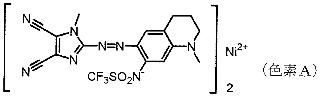


Claims
Priority Applications (4)
| Application Number | Priority Date | Filing Date | Title |
|---|---|---|---|
| EP05765513A EP1764794A4 (en) | 2004-07-06 | 2005-07-05 | Optical recording medium |
| TW094122889A TW200606935A (en) | 2004-07-06 | 2005-07-06 | Optical recording medium |
| US11/412,958 US7427432B2 (en) | 2004-07-06 | 2006-04-28 | Optical recording medium |
| HK07107420.8A HK1099842A1 (en) | 2004-07-06 | 2007-07-11 | Optical recording medium |
Applications Claiming Priority (2)
| Application Number | Priority Date | Filing Date | Title |
|---|---|---|---|
| JP2004-199770 | 2004-07-06 | ||
| JP2004199770 | 2004-07-06 |
Related Child Applications (1)
| Application Number | Title | Priority Date | Filing Date |
|---|---|---|---|
| US11/412,958 Continuation US7427432B2 (en) | 2004-07-06 | 2006-04-28 | Optical recording medium |
Publications (1)
| Publication Number | Publication Date |
|---|---|
| WO2006004119A1 true WO2006004119A1 (en) | 2006-01-12 |
Family
ID=35782918
Family Applications (1)
| Application Number | Title | Priority Date | Filing Date |
|---|---|---|---|
| PCT/JP2005/012412 WO2006004119A1 (en) | 2004-07-06 | 2005-07-05 | Optical recording medium |
Country Status (6)
| Country | Link |
|---|---|
| US (1) | US7427432B2 (en) |
| EP (1) | EP1764794A4 (en) |
| CN (2) | CN101373619A (en) |
| HK (1) | HK1099842A1 (en) |
| TW (1) | TW200606935A (en) |
| WO (1) | WO2006004119A1 (en) |
Cited By (1)
| Publication number | Priority date | Publication date | Assignee | Title |
|---|---|---|---|---|
| EP1973111A1 (en) * | 2006-01-13 | 2008-09-24 | Mitsubishi Kagaku Media Co., Ltd. | Optical recording medium |
Families Citing this family (8)
| Publication number | Priority date | Publication date | Assignee | Title |
|---|---|---|---|---|
| WO2004093070A1 (en) * | 2003-04-14 | 2004-10-28 | Mitsubishi Chemical Corporation | Optical recording medium and recording/reproducing method therefor |
| JP2007283520A (en) * | 2006-04-13 | 2007-11-01 | Mitsubishi Kagaku Media Co Ltd | Thermosensitive printing layer and optical recording medium employing thereof |
| US20070298271A1 (en) * | 2006-06-23 | 2007-12-27 | 3M Innovative Properties Company | Multilayer optical film, method of making the same, and transaction card having the same |
| JP4783327B2 (en) * | 2007-04-19 | 2011-09-28 | 太陽誘電株式会社 | Optical information recording medium |
| JP5393045B2 (en) * | 2008-03-31 | 2014-01-22 | 太陽誘電株式会社 | Optical information recording medium |
| JP5478836B2 (en) * | 2008-05-01 | 2014-04-23 | ソニー株式会社 | Optical recording medium, liquid active energy ray-curable reactive cross-linked resin composition |
| CN107767887A (en) * | 2017-12-06 | 2018-03-06 | 苏州盤谷信息光学有限公司 | A kind of holographic memory device based on dichroic reflective layer |
| CN110632331A (en) * | 2019-10-31 | 2019-12-31 | 无锡锦帛诚医疗器械科技有限公司 | Dry tablet reagent for quantitative detection of total cholesterol |
Citations (4)
| Publication number | Priority date | Publication date | Assignee | Title |
|---|---|---|---|---|
| JPH03232132A (en) * | 1990-02-07 | 1991-10-16 | Taiyo Yuden Co Ltd | Optical information recording medium |
| JP2002230834A (en) * | 2000-06-26 | 2002-08-16 | Tdk Corp | Optical information medium, method of manufacturing for the same, recording or reproducing method for the same and method of inspecting the same |
| JP2004055177A (en) * | 2002-07-16 | 2004-02-19 | Dainippon Printing Co Ltd | Electroluminescent display device and manufacturing method of the same |
| JP2004118966A (en) * | 2002-09-27 | 2004-04-15 | Teijin Bayer Polytec Ltd | Optical disk |
Family Cites Families (11)
| Publication number | Priority date | Publication date | Assignee | Title |
|---|---|---|---|---|
| JPH09320116A (en) * | 1996-05-31 | 1997-12-12 | Victor Co Of Japan Ltd | Optical disk |
| JPH10302309A (en) * | 1997-04-25 | 1998-11-13 | Sony Corp | Optical recording medium |
| JP3783652B2 (en) * | 1998-09-09 | 2006-06-07 | 三菱化学メディア株式会社 | Optical information recording medium and optical recording method |
| JP2000311384A (en) | 1999-04-26 | 2000-11-07 | Fuji Photo Film Co Ltd | Optical information recording medium |
| US20040027981A1 (en) * | 2000-10-24 | 2004-02-12 | Schoeppel Wolfgang G | Optical storage medium |
| JP2002157783A (en) * | 2000-11-15 | 2002-05-31 | Sharp Corp | Optical information recording medium |
| DE60207487T2 (en) * | 2001-06-04 | 2006-08-10 | FUJI PHOTO FILM CO., LTD., Minamiashigara | Optical recording medium |
| JP2003242675A (en) * | 2002-02-13 | 2003-08-29 | Sharp Corp | Optical information recording medium |
| JP4105589B2 (en) | 2002-05-31 | 2008-06-25 | Tdk株式会社 | Optical recording medium and optical recording method |
| JP4642312B2 (en) * | 2002-08-07 | 2011-03-02 | シャープ株式会社 | Information recording medium and information processing apparatus using the information recording medium |
| TWI233116B (en) * | 2002-09-06 | 2005-05-21 | Mitsubishi Chem Corp | Optical information recording medium |
-
2005
- 2005-07-05 WO PCT/JP2005/012412 patent/WO2006004119A1/en not_active Application Discontinuation
- 2005-07-05 CN CNA2008101701056A patent/CN101373619A/en active Pending
- 2005-07-05 CN CNB2005800018907A patent/CN100470649C/en not_active Expired - Fee Related
- 2005-07-05 EP EP05765513A patent/EP1764794A4/en not_active Withdrawn
- 2005-07-06 TW TW094122889A patent/TW200606935A/en not_active IP Right Cessation
-
2006
- 2006-04-28 US US11/412,958 patent/US7427432B2/en active Active
-
2007
- 2007-07-11 HK HK07107420.8A patent/HK1099842A1/en not_active IP Right Cessation
Patent Citations (4)
| Publication number | Priority date | Publication date | Assignee | Title |
|---|---|---|---|---|
| JPH03232132A (en) * | 1990-02-07 | 1991-10-16 | Taiyo Yuden Co Ltd | Optical information recording medium |
| JP2002230834A (en) * | 2000-06-26 | 2002-08-16 | Tdk Corp | Optical information medium, method of manufacturing for the same, recording or reproducing method for the same and method of inspecting the same |
| JP2004055177A (en) * | 2002-07-16 | 2004-02-19 | Dainippon Printing Co Ltd | Electroluminescent display device and manufacturing method of the same |
| JP2004118966A (en) * | 2002-09-27 | 2004-04-15 | Teijin Bayer Polytec Ltd | Optical disk |
Non-Patent Citations (1)
| Title |
|---|
| See also references of EP1764794A4 * |
Cited By (4)
| Publication number | Priority date | Publication date | Assignee | Title |
|---|---|---|---|---|
| EP1973111A1 (en) * | 2006-01-13 | 2008-09-24 | Mitsubishi Kagaku Media Co., Ltd. | Optical recording medium |
| EP1973111A4 (en) * | 2006-01-13 | 2009-09-09 | Mitsubishi Kagaku Media Co Ltd | Optical recording medium |
| CN101310336B (en) * | 2006-01-13 | 2010-10-13 | 三菱化学媒体股份有限公司 | Optical recording medium |
| US8114496B2 (en) | 2006-01-13 | 2012-02-14 | Mitsubishi Kagaku Media Co., Ltd. | Optical recording medium |
Also Published As
| Publication number | Publication date |
|---|---|
| TW200606935A (en) | 2006-02-16 |
| CN101373619A (en) | 2009-02-25 |
| US7427432B2 (en) | 2008-09-23 |
| HK1099842A1 (en) | 2007-08-24 |
| EP1764794A1 (en) | 2007-03-21 |
| EP1764794A4 (en) | 2009-01-28 |
| CN1906681A (en) | 2007-01-31 |
| US20060194017A1 (en) | 2006-08-31 |
| CN100470649C (en) | 2009-03-18 |
| TWI360122B (en) | 2012-03-11 |
Similar Documents
| Publication | Publication Date | Title |
|---|---|---|
| US7672215B2 (en) | Optical recording medium and recording/reading method therefor | |
| WO2006004119A1 (en) | Optical recording medium | |
| JP4642539B2 (en) | Optical recording medium | |
| EP1739667B1 (en) | Optical recording medium | |
| US8075972B2 (en) | Optical recording medium | |
| TWI377572B (en) | ||
| JP4238170B2 (en) | Optical recording medium | |
| JP2006048905A (en) | Optical recording medium | |
| JP4238518B2 (en) | Optical recording medium and manufacturing method thereof | |
| JP4171674B2 (en) | Optical recording medium, optical recording medium film thickness measuring method, film thickness controlling method, manufacturing method, film thickness measuring apparatus, and film thickness controlling apparatus | |
| JP4050993B2 (en) | Optical recording medium, optical recording medium thickness measurement method, film thickness control method, and manufacturing method | |
| JP4603996B2 (en) | Optical recording medium | |
| US8394480B2 (en) | Optical information recording medium and manufacturing method therefor | |
| JP2004288264A (en) | Optical recording medium and method of manufacturing optical recording medium | |
| JP3978402B2 (en) | Method for producing optical recording medium and method for producing laminate for optical recording medium | |
| JP2003331473A (en) | Optical recording medium | |
| JP2007066354A (en) | Optical recording medium and its manufacturing method | |
| WO2006093038A1 (en) | Stamper, die and method for manufacturing optical disc substrate | |
| JP2007066379A (en) | Method of manufacturing optical recording medium | |
| JP2005339769A (en) | Optical recording medium | |
| JP2004318985A (en) | Optical recording medium, recording and reproducing method of optical recording medium, and manufacturing method of optical recording medium | |
| JP2008226328A (en) | Optical information recording medium |
Legal Events
| Date | Code | Title | Description |
|---|---|---|---|
| AK | Designated states |
Kind code of ref document: A1 Designated state(s): AE AG AL AM AT AU AZ BA BB BG BR BW BY BZ CA CH CN CO CR CU CZ DE DK DM DZ EC EE EG ES FI GB GD GE GH GM HR HU ID IL IN IS KE KG KM KP KR KZ LC LK LR LS LT LU LV MA MD MG MK MN MW MX MZ NA NG NI NO NZ OM PG PH PL PT RO RU SC SD SE SG SK SL SM SY TJ TM TN TR TT TZ UA UG US UZ VC VN YU ZA ZM ZW |
|
| AL | Designated countries for regional patents |
Kind code of ref document: A1 Designated state(s): BW GH GM KE LS MW MZ NA SD SL SZ TZ UG ZM ZW AM AZ BY KG KZ MD RU TJ TM AT BE BG CH CY CZ DE DK EE ES FI FR GB GR HU IE IS IT LT LU LV MC NL PL PT RO SE SI SK TR BF BJ CF CG CI CM GA GN GQ GW ML MR NE SN TD TG |
|
| 121 | Ep: the epo has been informed by wipo that ep was designated in this application | ||
| WWE | Wipo information: entry into national phase |
Ref document number: 930/KOLNP/2006 Country of ref document: IN |
|
| WWE | Wipo information: entry into national phase |
Ref document number: 11412958 Country of ref document: US Ref document number: 2005765513 Country of ref document: EP |
|
| WWE | Wipo information: entry into national phase |
Ref document number: 200580001890.7 Country of ref document: CN |
|
| WWP | Wipo information: published in national office |
Ref document number: 11412958 Country of ref document: US |
|
| NENP | Non-entry into the national phase |
Ref country code: DE |
|
| WWW | Wipo information: withdrawn in national office |
Ref document number: DE |
|
| WWP | Wipo information: published in national office |
Ref document number: 2005765513 Country of ref document: EP |