WO2004068045A1 - Supercritical refrigerating cycle - Google Patents
Supercritical refrigerating cycle Download PDFInfo
- Publication number
- WO2004068045A1 WO2004068045A1 PCT/KR2004/000143 KR2004000143W WO2004068045A1 WO 2004068045 A1 WO2004068045 A1 WO 2004068045A1 KR 2004000143 W KR2004000143 W KR 2004000143W WO 2004068045 A1 WO2004068045 A1 WO 2004068045A1
- Authority
- WO
- WIPO (PCT)
- Prior art keywords
- refrigerant
- compressor
- refrigerating cycle
- air velocity
- discharge pressure
- Prior art date
Links
- 239000003507 refrigerant Substances 0.000 claims abstract description 99
- 239000003570 air Substances 0.000 claims abstract description 63
- 239000012080 ambient air Substances 0.000 claims abstract description 35
- CURLTUGMZLYLDI-UHFFFAOYSA-N Carbon dioxide Chemical compound O=C=O CURLTUGMZLYLDI-UHFFFAOYSA-N 0.000 claims description 44
- 229910002092 carbon dioxide Inorganic materials 0.000 claims description 22
- 239000001569 carbon dioxide Substances 0.000 claims description 22
- 230000001276 controlling effect Effects 0.000 claims description 15
- 238000001704 evaporation Methods 0.000 claims description 8
- 238000001816 cooling Methods 0.000 claims description 6
- 238000013507 mapping Methods 0.000 claims description 6
- 230000001105 regulatory effect Effects 0.000 claims description 3
- 238000005191 phase separation Methods 0.000 claims description 2
- 230000006835 compression Effects 0.000 description 7
- 238000007906 compression Methods 0.000 description 7
- 230000003247 decreasing effect Effects 0.000 description 6
- 238000010586 diagram Methods 0.000 description 6
- 239000007788 liquid Substances 0.000 description 6
- 230000008020 evaporation Effects 0.000 description 5
- 238000000034 method Methods 0.000 description 4
- 238000004378 air conditioning Methods 0.000 description 3
- 238000012546 transfer Methods 0.000 description 3
- 230000003578 releasing effect Effects 0.000 description 2
- LVGUZGTVOIAKKC-UHFFFAOYSA-N 1,1,1,2-tetrafluoroethane Chemical compound FCC(F)(F)F LVGUZGTVOIAKKC-UHFFFAOYSA-N 0.000 description 1
- 238000013459 approach Methods 0.000 description 1
- 238000007664 blowing Methods 0.000 description 1
- 238000009835 boiling Methods 0.000 description 1
- 230000005494 condensation Effects 0.000 description 1
- 238000009833 condensation Methods 0.000 description 1
- 238000013461 design Methods 0.000 description 1
- 238000005516 engineering process Methods 0.000 description 1
- 230000007613 environmental effect Effects 0.000 description 1
- 239000012530 fluid Substances 0.000 description 1
- 238000004519 manufacturing process Methods 0.000 description 1
- 238000012986 modification Methods 0.000 description 1
- 230000004048 modification Effects 0.000 description 1
- 230000000704 physical effect Effects 0.000 description 1
- 238000011144 upstream manufacturing Methods 0.000 description 1
- 238000010792 warming Methods 0.000 description 1
Classifications
-
- F—MECHANICAL ENGINEERING; LIGHTING; HEATING; WEAPONS; BLASTING
- F25—REFRIGERATION OR COOLING; COMBINED HEATING AND REFRIGERATION SYSTEMS; HEAT PUMP SYSTEMS; MANUFACTURE OR STORAGE OF ICE; LIQUEFACTION SOLIDIFICATION OF GASES
- F25B—REFRIGERATION MACHINES, PLANTS OR SYSTEMS; COMBINED HEATING AND REFRIGERATION SYSTEMS; HEAT PUMP SYSTEMS
- F25B9/00—Compression machines, plants or systems, in which the refrigerant is air or other gas of low boiling point
- F25B9/002—Compression machines, plants or systems, in which the refrigerant is air or other gas of low boiling point characterised by the refrigerant
- F25B9/008—Compression machines, plants or systems, in which the refrigerant is air or other gas of low boiling point characterised by the refrigerant the refrigerant being carbon dioxide
-
- G—PHYSICS
- G07—CHECKING-DEVICES
- G07F—COIN-FREED OR LIKE APPARATUS
- G07F19/00—Complete banking systems; Coded card-freed arrangements adapted for dispensing or receiving monies or the like and posting such transactions to existing accounts, e.g. automatic teller machines
- G07F19/20—Automatic teller machines [ATMs]
- G07F19/201—Accessories of ATMs
-
- B—PERFORMING OPERATIONS; TRANSPORTING
- B60—VEHICLES IN GENERAL
- B60H—ARRANGEMENTS OF HEATING, COOLING, VENTILATING OR OTHER AIR-TREATING DEVICES SPECIALLY ADAPTED FOR PASSENGER OR GOODS SPACES OF VEHICLES
- B60H1/00—Heating, cooling or ventilating [HVAC] devices
- B60H1/32—Cooling devices
- B60H1/3204—Cooling devices using compression
- B60H1/3205—Control means therefor
- B60H1/3217—Control means therefor for high pressure, inflamable or poisonous refrigerants causing danger in case of accidents
-
- B—PERFORMING OPERATIONS; TRANSPORTING
- B60—VEHICLES IN GENERAL
- B60H—ARRANGEMENTS OF HEATING, COOLING, VENTILATING OR OTHER AIR-TREATING DEVICES SPECIALLY ADAPTED FOR PASSENGER OR GOODS SPACES OF VEHICLES
- B60H1/00—Heating, cooling or ventilating [HVAC] devices
- B60H1/32—Cooling devices
- B60H2001/3236—Cooling devices information from a variable is obtained
- B60H2001/3239—Cooling devices information from a variable is obtained related to flow
- B60H2001/3241—Cooling devices information from a variable is obtained related to flow of air
-
- B—PERFORMING OPERATIONS; TRANSPORTING
- B60—VEHICLES IN GENERAL
- B60H—ARRANGEMENTS OF HEATING, COOLING, VENTILATING OR OTHER AIR-TREATING DEVICES SPECIALLY ADAPTED FOR PASSENGER OR GOODS SPACES OF VEHICLES
- B60H1/00—Heating, cooling or ventilating [HVAC] devices
- B60H1/32—Cooling devices
- B60H2001/3236—Cooling devices information from a variable is obtained
- B60H2001/3248—Cooling devices information from a variable is obtained related to pressure
- B60H2001/325—Cooling devices information from a variable is obtained related to pressure of the refrigerant at a compressing unit
-
- B—PERFORMING OPERATIONS; TRANSPORTING
- B60—VEHICLES IN GENERAL
- B60H—ARRANGEMENTS OF HEATING, COOLING, VENTILATING OR OTHER AIR-TREATING DEVICES SPECIALLY ADAPTED FOR PASSENGER OR GOODS SPACES OF VEHICLES
- B60H1/00—Heating, cooling or ventilating [HVAC] devices
- B60H1/32—Cooling devices
- B60H2001/3236—Cooling devices information from a variable is obtained
- B60H2001/3255—Cooling devices information from a variable is obtained related to temperature
- B60H2001/3258—Cooling devices information from a variable is obtained related to temperature of the air at a condensing unit
-
- B—PERFORMING OPERATIONS; TRANSPORTING
- B60—VEHICLES IN GENERAL
- B60H—ARRANGEMENTS OF HEATING, COOLING, VENTILATING OR OTHER AIR-TREATING DEVICES SPECIALLY ADAPTED FOR PASSENGER OR GOODS SPACES OF VEHICLES
- B60H1/00—Heating, cooling or ventilating [HVAC] devices
- B60H1/32—Cooling devices
- B60H2001/3269—Cooling devices output of a control signal
- B60H2001/3285—Cooling devices output of a control signal related to an expansion unit
-
- F—MECHANICAL ENGINEERING; LIGHTING; HEATING; WEAPONS; BLASTING
- F25—REFRIGERATION OR COOLING; COMBINED HEATING AND REFRIGERATION SYSTEMS; HEAT PUMP SYSTEMS; MANUFACTURE OR STORAGE OF ICE; LIQUEFACTION SOLIDIFICATION OF GASES
- F25B—REFRIGERATION MACHINES, PLANTS OR SYSTEMS; COMBINED HEATING AND REFRIGERATION SYSTEMS; HEAT PUMP SYSTEMS
- F25B2309/00—Gas cycle refrigeration machines
- F25B2309/06—Compression machines, plants or systems characterised by the refrigerant being carbon dioxide
- F25B2309/061—Compression machines, plants or systems characterised by the refrigerant being carbon dioxide with cycle highest pressure above the supercritical pressure
-
- F—MECHANICAL ENGINEERING; LIGHTING; HEATING; WEAPONS; BLASTING
- F25—REFRIGERATION OR COOLING; COMBINED HEATING AND REFRIGERATION SYSTEMS; HEAT PUMP SYSTEMS; MANUFACTURE OR STORAGE OF ICE; LIQUEFACTION SOLIDIFICATION OF GASES
- F25B—REFRIGERATION MACHINES, PLANTS OR SYSTEMS; COMBINED HEATING AND REFRIGERATION SYSTEMS; HEAT PUMP SYSTEMS
- F25B2500/00—Problems to be solved
- F25B2500/19—Calculation of parameters
-
- F—MECHANICAL ENGINEERING; LIGHTING; HEATING; WEAPONS; BLASTING
- F25—REFRIGERATION OR COOLING; COMBINED HEATING AND REFRIGERATION SYSTEMS; HEAT PUMP SYSTEMS; MANUFACTURE OR STORAGE OF ICE; LIQUEFACTION SOLIDIFICATION OF GASES
- F25B—REFRIGERATION MACHINES, PLANTS OR SYSTEMS; COMBINED HEATING AND REFRIGERATION SYSTEMS; HEAT PUMP SYSTEMS
- F25B2600/00—Control issues
- F25B2600/17—Control issues by controlling the pressure of the condenser
-
- F—MECHANICAL ENGINEERING; LIGHTING; HEATING; WEAPONS; BLASTING
- F25—REFRIGERATION OR COOLING; COMBINED HEATING AND REFRIGERATION SYSTEMS; HEAT PUMP SYSTEMS; MANUFACTURE OR STORAGE OF ICE; LIQUEFACTION SOLIDIFICATION OF GASES
- F25B—REFRIGERATION MACHINES, PLANTS OR SYSTEMS; COMBINED HEATING AND REFRIGERATION SYSTEMS; HEAT PUMP SYSTEMS
- F25B2600/00—Control issues
- F25B2600/25—Control of valves
- F25B2600/2513—Expansion valves
-
- F—MECHANICAL ENGINEERING; LIGHTING; HEATING; WEAPONS; BLASTING
- F25—REFRIGERATION OR COOLING; COMBINED HEATING AND REFRIGERATION SYSTEMS; HEAT PUMP SYSTEMS; MANUFACTURE OR STORAGE OF ICE; LIQUEFACTION SOLIDIFICATION OF GASES
- F25B—REFRIGERATION MACHINES, PLANTS OR SYSTEMS; COMBINED HEATING AND REFRIGERATION SYSTEMS; HEAT PUMP SYSTEMS
- F25B2700/00—Sensing or detecting of parameters; Sensors therefor
- F25B2700/19—Pressures
- F25B2700/193—Pressures of the compressor
- F25B2700/1931—Discharge pressures
-
- F—MECHANICAL ENGINEERING; LIGHTING; HEATING; WEAPONS; BLASTING
- F25—REFRIGERATION OR COOLING; COMBINED HEATING AND REFRIGERATION SYSTEMS; HEAT PUMP SYSTEMS; MANUFACTURE OR STORAGE OF ICE; LIQUEFACTION SOLIDIFICATION OF GASES
- F25B—REFRIGERATION MACHINES, PLANTS OR SYSTEMS; COMBINED HEATING AND REFRIGERATION SYSTEMS; HEAT PUMP SYSTEMS
- F25B2700/00—Sensing or detecting of parameters; Sensors therefor
- F25B2700/21—Temperatures
- F25B2700/2106—Temperatures of fresh outdoor air
-
- F—MECHANICAL ENGINEERING; LIGHTING; HEATING; WEAPONS; BLASTING
- F25—REFRIGERATION OR COOLING; COMBINED HEATING AND REFRIGERATION SYSTEMS; HEAT PUMP SYSTEMS; MANUFACTURE OR STORAGE OF ICE; LIQUEFACTION SOLIDIFICATION OF GASES
- F25B—REFRIGERATION MACHINES, PLANTS OR SYSTEMS; COMBINED HEATING AND REFRIGERATION SYSTEMS; HEAT PUMP SYSTEMS
- F25B40/00—Subcoolers, desuperheaters or superheaters
-
- F—MECHANICAL ENGINEERING; LIGHTING; HEATING; WEAPONS; BLASTING
- F25—REFRIGERATION OR COOLING; COMBINED HEATING AND REFRIGERATION SYSTEMS; HEAT PUMP SYSTEMS; MANUFACTURE OR STORAGE OF ICE; LIQUEFACTION SOLIDIFICATION OF GASES
- F25B—REFRIGERATION MACHINES, PLANTS OR SYSTEMS; COMBINED HEATING AND REFRIGERATION SYSTEMS; HEAT PUMP SYSTEMS
- F25B49/00—Arrangement or mounting of control or safety devices
- F25B49/02—Arrangement or mounting of control or safety devices for compression type machines, plants or systems
- F25B49/027—Condenser control arrangements
-
- G—PHYSICS
- G07—CHECKING-DEVICES
- G07D—HANDLING OF COINS OR VALUABLE PAPERS, e.g. TESTING, SORTING BY DENOMINATIONS, COUNTING, DISPENSING, CHANGING OR DEPOSITING
- G07D2211/00—Paper-money handling devices
Definitions
- the present invention relates to a supercritical refrigerating cycle, and more particularly, a supercritical refrigerating cycle which calculates an optimum target discharge pressure of a refrigerant according to an ambient air temperature and an air velocity flowing into a gas cooler, compares a difference between the optimum target discharge pressure and a real discharge pressure of the refrigerant, and feedback controls an opening of an expansion valve as expansion means for controlling a refrigerant discharge pressure.
- a refrigerant such as R134a is generally known as one of major factors for environmental disruption such as global warming.
- a substitute refrigerant such as carbon dioxide is being developed and a supercritical refrigerating cycle using the carbon dioxide as the substitute refrigerant is being developed to protect environment.
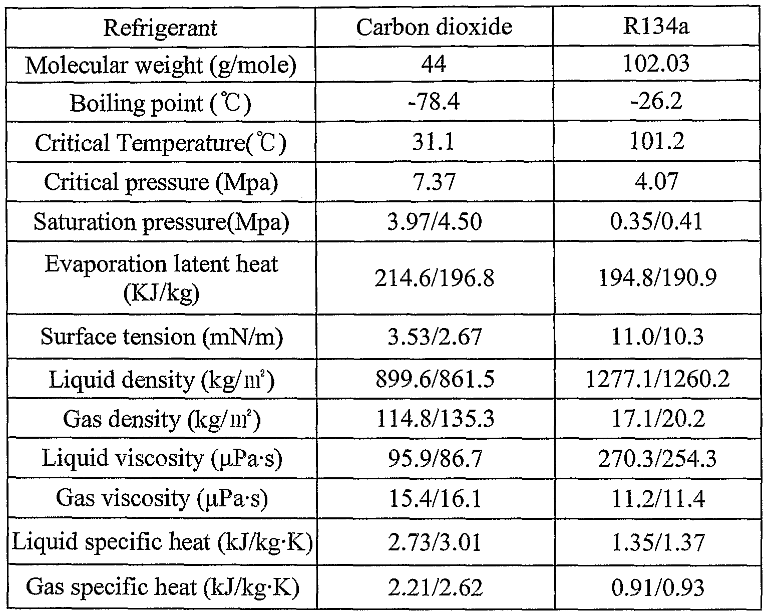
- the carbon dioxide as a refrigerant has advantages such as an excellent compression efficiency due to a lower operating compression ratio and a lower temperature approach (an input air temperature as a secondary fluid - a discharge refrigerant temperature) compared to a conventional refrigerant due to an excellent heat transfer characteristic. That is, since the heat transfer characteristic is excellent, heat can be easily transferred even if a temperature difference between a refrigerant and an ambient air is small. Further, the carbon dioxide comes into the spotlight as a refrigerant of a heat pump which should absorb external heat during a cold winter season. Furthermore, the carbon dioxide has the other advantages compared to the conventional refrigerant R134a, which shows in TABLE 1. [TABLE 1 ]
- the carbon dioxide has a lower critical temperature and a higher evaporation pressure compared to R134a as a conventional refrigerant. Therefore, a supercritical refrigerating cycle using the carbon dioxide as a refrigerant can be expected to a cycle passing over a critical pressure. Further, as the carbon dioxide has excellent thermodynamic physical properties, a volumetric capacity (evaporation latent heat x gas density) of the carbon dioxide is about 7 to 8 times compared to a volumetric capacity of the R134a, thereby reducing a discharge volume of a compressor included in a supercritical refrigerating cycle. Furthermore, as the carbon dioxide has an excellent boiling heat transfer rate due to a lower surface tension, a higher specific heat, and a lower liquid viscosity, it is superior to the R134a in a pressure drop.
- the supercritical refrigerating cycle using the carbon dioxide as a refrigerant has characteristics of a higher gas cooling pressure (conventional condensation pressure) as well as a higher evaporation pressure compared to a conventional refrigerating cycle using the R134a as a refrigerant. That is, an evaporation pressure in the supercritical refrigerating cycle is higher than about 10 times compared to the a conventional refrigerating cycle and a gas cooling pressure is higher than about 7 times (about 120bar). Therefore, an apparatus and a system for protecting some parts such as a compressor, a gas cooler, and etc. are being developed which is described in Japan laid-open patent No. 2000-234811 and a system control technology considering an air conditioning efficiency is being developed which is described in Japan laid-open patent No. 2001-194017.
- the supercritical refrigerating cycle using the carbon dioxide as a refrigerant should be optimally controlled to operate in a high pressure and fit the specific characteristics of the carbon dioxide.
- a compression power using the carbon dioxide may be needed to be higher than a compression power using the R134a because a compression ratio is lower but an inhaling pressure is higher, thereby lowering a system efficiency even if the air conditioner has excellent performance.
- the supercritical refrigerating cycle controls an amount of discharge refrigerant from a compressor by adjusting an opening of an expansion valve in response to signals from a plurality of sensors such as a gas cooler inlet temperature sensor, a gas cooler outlet temperature sensor, a gas cooler outlet pressure sensor, an evaporation outlet pressure sensor, and etc.
- a gas cooler inlet temperature sensor such as a gas cooler inlet temperature sensor, a gas cooler outlet temperature sensor, a gas cooler outlet pressure sensor, an evaporation outlet pressure sensor, and etc.
- Those sensors are too many, thereby increasing cost for manufacturing the supercritical refrigerating cycle, being difficult for fine controlling due to a complex control logic of the system, and being difficult for applying a theoretical coefficient of the compressor, an efficient of the compressor, and an operational torque of the compressor.
- the conventional supercritical refrigerating cycle does not consider a heat exchanging efficiency according to an ambient air flow rate, it is not an optimal controlling method.
- an optimum target discharge pressure of a refrigerant is calculated according to an ambient air temperature and an air velocity flowing into a gas cooler, a difference between the optimum target discharge pressure and a real discharge pressure of the refrigerant is compared, and an opening of an expansion valve as expansion means is feedback controlled for controlling a refrigerant discharge pressure.
- It is therefore an object of the present invention to provide a supercritical refrigerating cycle which includes: a compressor for inhaling carbon dioxide as a refrigerant and compressing the carbon dioxide to a supercritical state;; a gas cooler for cooling the refrigerant discharged from the compressor with a high temperature and a high pressure; expansion means for regulating the refrigerant flow rate with reducing a pressure of the refrigerant discharged from the gas cooler by expansion of the refrigerant; an evaporator for evaporating the refrigerant entered from the expansion means by heat exchanging with an ambient air; an internal heat exchanger for heat exchanging the refrigerant flowing into the compressor from the evaporator with the refrigerant flowing into the expansion means from the gas cooler; an accumulator installed between the evaporator and the internal heat exchanger for supplying only a gas refrigerant to the compressor by a phase separation of the refrigerant ; air velocity sensing means for measuring an air velocity entered into the gas cooler; air temperature sensing means for
- the air temperature sensing means is an ambient temperature sensor.
- the calculating unit stores a target discharge pressure as a mapping data according to the air velocity and the ambient air temperature.
- Fig. 1 is a schematic (or block) diagram of a supercritical refrigerating cycle according to an embodiment of the present invention
- Fig.2 is a block diagram of a control unit in a supercritical refrigerating cycle according to an embodiment of the present invention
- Fig. 3 is a block diagram showing a feedback control relationship of a supercritical refrigerating cycle according to an embodiment of the present invention
- Fig. 4 shows a variation of a refrigerant discharge pressure according to an ambient air temperature in a supercritical refrigerating cycle according to an embodiment of the present invention
- Fig. 5 shows a variation of a refrigerant discharge pressure according to an air velocity in a supercritical refrigerating cycle according to an embodiment of the present invention
- Fig. 6 is a flow chart showing a method for controlling a supercritical refrigerating cycle according to an embodiment of the present invention.
- Fig. 7 is a schematic diagram of a supercritical refrigerating cycle according to an embodiment of the present invention in case an air velocity sensing means is a tachometer.
- Fig. 1 is a schematic diagram of a supercritical refrigerating cycle according to an embodiment of the present invention.
- Fig.2 is a block diagram of a controller for the supercritical refrigerating cycle according to an embodiment of the present invention.
- the supercritical refrigerating cycle according to an embodiment of the present invention includes a compressor 100, a gas cooler 110, an internal heat exchanger 120, expansion means 130, an evaporator 140, an accumulator 150, and a control unit 200.
- the compressor 100 inhales carbon dioxide, compresses the carbon dioxide to a supercritical state having a high pressure over a critical pressure, and discharges the compressed carbon dioxide.
- the compressor 100 can be a variable capacity type compressor.
- the refrigerant in a supercritical state having a high temperature and a high pressure discharged from the compressor 100 passes an inside of the gas cooler 110 and is changed to a lower temperature by heat exchanging with an external air flow flowing into an outside of the gas cooler 110, wherein a cooling fan 112 blows the external air into the outside of the gas cooler 110.
- the heat exchanger 120 has a function of lowering the temperature of a refrigerant discharged from the gas cooler 110 by heat exchanging with a refrigerant discharged from the evaporator 140, so that the refrigerant discharged from the gas cooler 110 has a lower temperature than an external air.
- the heat exchanger 120 includes a first heat exchanging portion 122 for passing the refrigerant and supplying the refiigerant to the expansion means 130 and a second heat exchanging portion 124 for returning the refrigerant discharged from the evaporator 140 to the compressor 100.
- the expansion means 130 expands to decompress and cool the refrigerant passing the first heat exchanging portion 122 of the heat exchanger 120, changes the refrigerant into a low pressure below a critical pressure, and controls the flow rate of the refrigerant into the evaporator 140.
- An expander can be used as the expansion means 130.
- the evaporator 140 has a function of lowering the temperature of an air blowing by a fan 142 into an outside of the evaporator 140 by heat exchanging with a refrigerant discharged from the expansion means 130 of electromagnetic expansion valve, so that the air has a lower temperature while evaporating the refrigerant.
- the air having the lower temperature is supplied into an inside of an automobile through openings (not shown) opened in an air-conditioning case (not shown) according to an air-conditioning mode, so that the inside of the automobile can be cooled.
- the refrigerant discharged from the evaporator 140 passes the second heat exchanging portion 124 of the heat exchanger 120 and exchanges heat with the refrigerant discharged from the first heat exchanging portion 122, so that a temperature of the refrigerant discharged from the evaporator 140 is increased and returned into the compressor 100 while cooling the refrigerant discharged from the first heat exchanging portion 122.
- the refrigerant discharged from the evaporator 140 can include a liquid refrigerant. If the liquid refrigerant is entered into the compressor 100, a pressure sensor (not shown) in the compressor 100 can be damaged by a liquid compression, so that the refrigerant discharged from the evaporator 140 is temporally stored in the accumulator 150 for separating a gas refrigerant from the liquid refrigerant, and only the gas refrigerant can be returned to the compressor 100 through the heat exchanger 120.
- the accumulator 150 is configured between the evaporator 140 and the heat exchanger 120. Alternatively, the accumulator 150 can be incorporated into the second heat exchanging portion 124 of the heat exchanger 120.
- the accumulator 150 is preferably configured to an inlet part of the second heat exchanging portion 124 between downstream direction of the evaporator 140 and upstream direction of the second heat exchanging portion 124. That is, the refrigerant flowing in the second heat exchanging portion 124 of the heat exchanger
- the second heat exchanging portion 124 can have a function of the accumulator 150.
- a high pressure over a critical pressure is applied between the compressor 100 and the expansion valve 130 and a low pressure below the critical pressure is applied between the expansion valve 130 and the compressor 100. If a compression ratio between an inlet and an outlet of the compressor 100 and a flow rate of the refrigerant are optimized, a coefficient of performance (COP) of the refrigerator will be increased.
- COP coefficient of performance
- the supercritical refrigerating cycle calculates an optimum target discharge pressure of the refrigerant according to an ambient temperature and an air velocity flowing into the gas cooler 110, compares an optimum target discharge pressure of the refrigerant and a real discharge pressure of the refrigerant, and controls an opening of the electromagnetic expansion valve as the expansion means 130, thereby feedback controlling a refrigerant discharge pressure.
- an ambient temperature and an air velocity are included as factors for controlling the refrigerating cycle.
- the reason for including the ambient temperature is that if the ambient temperature is changed, an operation of the compressor should be changed and a discharge pressure of the refrigerant should be changed to be comfortable.
- the reason for including the air velocity is that if the air velocity is increased or decreased, an external air flow rate is increased or decreased, and a heat releasing efficiency of the gas cooler 110 is changed, thereby changing a discharge pressure of the compressor 100.
- a control unit 200 of the supercritical refrigerating cycle of an embodiment of the present invention further includes an air velocity sensing means 220, 240 for measuring an air velocity entered to the gas cooler 110, an ambient air temperature sensor 230 for sensing an ambient air temperature entered to the gas cooler 110, a pressure sensor 300 for sensing a refrigerant discharge pressure discharged from the compressor 110, a calculating unit for calculating an optimum target discharge pressure of the compressor 100 from the air velocity sensed by the air velocity sensing means 220 and the ambient air temperature by the ambient air temperature sensor 230, a comparator for comparing a difference between the optimum target discharge pressure calculated from the calculating unit and the refrigerant discharge pressure from the compressor 100, and a controller 210 for controlling an opening of the expansion means 130 according to a difference between the optimum target discharge pressure and the refrigerant discharge pressure from the compressor 100.
- the air velocity sensing means 220, 240 can be an air velocity sensor 240 shown in Fig. 1 or a tachometer 220 shown in Figs. 1 and 7 installed in a car.
- Fig. 4 shows a variation of a refrigerant discharge pressure according to an ambient air temperature.
- the refrigerant discharge pressure is proportionally increased. That is, when the ambient air temperature is increased, a driving force of the compressor 100 is increased to keep an appropriate temperature.
- Fig. 5 shows a variation of the refrigerant discharge pressure and an ambient air flow rate.
- Fig. 5 does not show a variation of the refrigerant discharge pressure and an air velocity.
- a variation of the discharge pressure according to an air velocity can be recognized, because the ambient air flow is increased with increasing of the air velocity and the ambient air flow is decreased with the decreasing of the air velocity.
- Fig. 6 is a flow chart showing a method for controlling the supercritical refrigerating cycle according to an embodiment of the present invention.
- an optimum discharge pressure of the refrigerant according to an ambient air temperature and an air velocity is stored in the controller 210 of the control unit 200 (S100). Examples of mapping data for the optimum discharge pressure of the refrigerant are shown in TABLE 2 according to an ambient air temperature and an air velocity.
- the data Al to D4 indicate optimum discharge pressures of the refrigerant according to an ambient air temperature and an air velocity.
- the optimum discharge pressures of refrigerant are set by respective ranges of the air temperature and the air velocity.
- the optimum discharge pressures varies according to an ambient air temperature and an air velocity
- the supercritical refrigerating cycle is initialized (SI 20) while storing the mapping date in the controller 210 of the control unit 200.
- the controller 210 reads an ambient temperature signal and an air velocity signal (rpm) through the ambient temperature sensor 230 and the air velocity sensing means 220, 240 (SI 30). The controller converts the analog signals of the ambient temperature signal and the air velocity signal (rpm) to digital signals (SI 40).
- the controller 210 reads an optimum target discharge pressure from the pre-stored mapping data corresponding to the ambient air temperature and the air velocity which are converted to digital signals by the controller 210(S150).
- the controller 210 reads a refiigerant discharge pressure at an outlet of the compressor 100 by the pressure sensor 300 (SI 60) and an analog signal of the discharge pressure inputted into the controller 210 is converted to a digital signal (SI 70).
- the controller 210 calculates a difference between the optimum target discharge pressure from the mapping data and the digital signal of the real discharge pressure (SI 80), and decides whether there is a difference (SI 90). If there is a difference, the controller
- an opening of the electromagnetic expansion valve 130 is automatically controlled according to an ambient air temperature and an air velocity, thereby optimally controlling a refrigerant discharge pressure and a flow rate of the compressor 100.
- an optimum target discharge pressure of the refiigerant is calculated according to an ambient air temperature and an air velocity flowing into the gas cooler 110, a difference between the optimum target discharge pressure and a real discharge pressure of the refrigerant is compared, the refrigerant discharge pressure is feedback controlled by regulating an opening of the expansion valve 130 according to the difference, thereby optimally controlling a refrigerant discharge pressure and a flow rate of the compressor 100 and improving performance and efficiency of the supercritical refrigerating cycle.
- the supercritical refrigerating cycle uses an ambient air temperature and an air velocity, thereby providing a simple control method having a few necessary parts and pertinently utilizing the change of the optimal control part by the air velocity.
Landscapes
- Physics & Mathematics (AREA)
- Engineering & Computer Science (AREA)
- Thermal Sciences (AREA)
- Mechanical Engineering (AREA)
- Finance (AREA)
- Accounting & Taxation (AREA)
- Business, Economics & Management (AREA)
- General Physics & Mathematics (AREA)
- Chemical & Material Sciences (AREA)
- Chemical Kinetics & Catalysis (AREA)
- General Engineering & Computer Science (AREA)
- Air-Conditioning For Vehicles (AREA)
- Air Conditioning Control Device (AREA)
Abstract
The present invention relates to a supercritical refrigerating cycle which calculates an optimum target discharge pressure of a refrigerant according to an ambient air temperature and an air velocity flowing into a gas cooler, compares a difference between the optimum target discharge pressure and a real discharge pressure of the refrigerant, and feedback controls an opening of an expansion valve as expansion means for controlling a refrigerant discharge pressure to thereby improve performance and efficiency of the supercritical refrigerating cycle.
Description
SUPERCRITICAL REFRIGERATING CYCLE
Technical Field
The present invention relates to a supercritical refrigerating cycle, and more particularly, a supercritical refrigerating cycle which calculates an optimum target discharge pressure of a refrigerant according to an ambient air temperature and an air velocity flowing into a gas cooler, compares a difference between the optimum target discharge pressure and a real discharge pressure of the refrigerant, and feedback controls an opening of an expansion valve as expansion means for controlling a refrigerant discharge pressure.
Description of the Related Art
A refrigerant such as R134a is generally known as one of major factors for environmental disruption such as global warming. Thus, a substitute refrigerant such as carbon dioxide is being developed and a supercritical refrigerating cycle using the carbon dioxide as the substitute refrigerant is being developed to protect environment.
The carbon dioxide as a refrigerant has advantages such as an excellent compression efficiency due to a lower operating compression ratio and a lower temperature approach (an input air temperature as a secondary fluid - a discharge refrigerant temperature) compared to a conventional refrigerant due to an excellent heat transfer characteristic. That is, since the heat transfer characteristic is excellent, heat can be easily transferred even if a temperature difference between a refrigerant and an ambient air is small. Further, the carbon dioxide comes into the spotlight as a refrigerant of a heat pump which should absorb external heat during a cold winter season. Furthermore, the carbon dioxide has the other advantages compared to the conventional refrigerant R134a, which shows in TABLE 1.
[TABLE 1 ]
(at 0°C/10°C)
Referring to TABLE 1, the carbon dioxide has a lower critical temperature and a higher evaporation pressure compared to R134a as a conventional refrigerant. Therefore, a supercritical refrigerating cycle using the carbon dioxide as a refrigerant can be expected to a cycle passing over a critical pressure. Further, as the carbon dioxide has excellent thermodynamic physical properties, a volumetric capacity (evaporation latent heat x gas density) of the carbon dioxide is about 7 to 8 times compared to a volumetric capacity of the R134a, thereby reducing a discharge volume of a compressor included in a supercritical refrigerating cycle. Furthermore, as the carbon dioxide has an excellent boiling heat transfer rate due to a lower surface tension, a higher specific heat, and a lower liquid viscosity, it is superior to the R134a in a pressure drop.
However, the supercritical refrigerating cycle using the carbon dioxide as a refrigerant has characteristics of a higher gas cooling pressure (conventional condensation pressure) as well as a higher evaporation pressure compared to a conventional refrigerating cycle using the R134a as a refrigerant. That is, an evaporation pressure in the supercritical refrigerating cycle is higher than about 10 times compared to the a conventional
refrigerating cycle and a gas cooling pressure is higher than about 7 times (about 120bar). Therefore, an apparatus and a system for protecting some parts such as a compressor, a gas cooler, and etc. are being developed which is described in Japan laid-open patent No. 2000-234811 and a system control technology considering an air conditioning efficiency is being developed which is described in Japan laid-open patent No. 2001-194017.
The supercritical refrigerating cycle using the carbon dioxide as a refrigerant should be optimally controlled to operate in a high pressure and fit the specific characteristics of the carbon dioxide. Specifically, a compression power using the carbon dioxide may be needed to be higher than a compression power using the R134a because a compression ratio is lower but an inhaling pressure is higher, thereby lowering a system efficiency even if the air conditioner has excellent performance.
Further, the supercritical refrigerating cycle controls an amount of discharge refrigerant from a compressor by adjusting an opening of an expansion valve in response to signals from a plurality of sensors such as a gas cooler inlet temperature sensor, a gas cooler outlet temperature sensor, a gas cooler outlet pressure sensor, an evaporation outlet pressure sensor, and etc. Those sensors are too many, thereby increasing cost for manufacturing the supercritical refrigerating cycle, being difficult for fine controlling due to a complex control logic of the system, and being difficult for applying a theoretical coefficient of the compressor, an efficient of the compressor, and an operational torque of the compressor. Furthermore, as the conventional supercritical refrigerating cycle does not consider a heat exchanging efficiency according to an ambient air flow rate, it is not an optimal controlling method.
Therefore, it is highly needed to design a new system and a control logic for fine controlling of a supercritical refrigerating cycle using a carbon dioxide as a refrigerant.
SUMMARY OF THE INVENTION
It is therefore an object of the present invention to improve performance and efficiency of a supercritical refrigerating cycle. According to an embodiment of the present invention, an optimum target discharge pressure of a refrigerant is calculated according to an ambient air temperature and an air velocity flowing into a gas cooler, a difference between the optimum target discharge pressure and a real discharge pressure of the refrigerant is compared, and an opening of an expansion valve as expansion means is
feedback controlled for controlling a refrigerant discharge pressure.
It is therefore an object of the present invention to provide a supercritical refrigerating cycle which includes: a compressor for inhaling carbon dioxide as a refrigerant and compressing the carbon dioxide to a supercritical state;; a gas cooler for cooling the refrigerant discharged from the compressor with a high temperature and a high pressure; expansion means for regulating the refrigerant flow rate with reducing a pressure of the refrigerant discharged from the gas cooler by expansion of the refrigerant; an evaporator for evaporating the refrigerant entered from the expansion means by heat exchanging with an ambient air; an internal heat exchanger for heat exchanging the refrigerant flowing into the compressor from the evaporator with the refrigerant flowing into the expansion means from the gas cooler; an accumulator installed between the evaporator and the internal heat exchanger for supplying only a gas refrigerant to the compressor by a phase separation of the refrigerant ; air velocity sensing means for measuring an air velocity entered into the gas cooler; air temperature sensing means for measuring an ambient air temperature entered into the gas cooler; a pressure sensor for measuring a refrigerant pressure discharged from the compressor; a calculating unit for calculating an optimum target discharge pressure for the compressor according to the air velocity measured by the air velocity sensing means and the ambient air temperature measured by the air temperature sensing means; a comparator for comparing a difference between the optimum target discharge pressure calculated by the calculating unit and the refrigerant pressure discharged from the compressor; and a controller including a signal output unit for outputting a control signal, the control signal being for controlling an opening of the expansion means according to the difference. According to an embodiment of the present invention, the expansion means is an electromagnetic expansion valve. The air velocity sensing means is an air velocity sensor.
The air temperature sensing means is an ambient temperature sensor. The calculating unit
stores a target discharge pressure as a mapping data according to the air velocity and the ambient air temperature.
Brief Description of the Drawings The above objects and other advantages of the present invention will become more apparent by describing in detail preferred embodiments thereof with reference to the attached drawings in which:
Fig. 1 is a schematic (or block) diagram of a supercritical refrigerating cycle according to an embodiment of the present invention; Fig.2 is a block diagram of a control unit in a supercritical refrigerating cycle according to an embodiment of the present invention;
Fig. 3 is a block diagram showing a feedback control relationship of a supercritical refrigerating cycle according to an embodiment of the present invention;
Fig. 4 shows a variation of a refrigerant discharge pressure according to an ambient air temperature in a supercritical refrigerating cycle according to an embodiment of the present invention;
Fig. 5 shows a variation of a refrigerant discharge pressure according to an air velocity in a supercritical refrigerating cycle according to an embodiment of the present invention; Fig. 6 is a flow chart showing a method for controlling a supercritical refrigerating cycle according to an embodiment of the present invention; and
Fig. 7 is a schematic diagram of a supercritical refrigerating cycle according to an embodiment of the present invention in case an air velocity sensing means is a tachometer.
Detailed Peseription of Preferred Embodiments
Hereinafter, preferred embodiments of the present invention will be described in detail with reference to the accompanying drawings. It should be noted that like reference numerals are used for designation of like or equivalent parts or portion for simplicity of illustration and explanation. Fig. 1 is a schematic diagram of a supercritical refrigerating cycle according to an embodiment of the present invention. Fig.2 is a block diagram of a controller for the supercritical refrigerating cycle according to an embodiment of the present invention.
Referring to Figs. 1 and 2, the supercritical refrigerating cycle according to an embodiment of the present invention includes a compressor 100, a gas cooler 110, an internal heat exchanger 120, expansion means 130, an evaporator 140, an accumulator 150, and a control unit 200. The compressor 100 inhales carbon dioxide, compresses the carbon dioxide to a supercritical state having a high pressure over a critical pressure, and discharges the compressed carbon dioxide. According to a preferred embodiment of the present invention, the compressor 100 can be a variable capacity type compressor. The refrigerant in a supercritical state having a high temperature and a high pressure discharged from the compressor 100 passes an inside of the gas cooler 110 and is changed to a lower temperature by heat exchanging with an external air flow flowing into an outside of the gas cooler 110, wherein a cooling fan 112 blows the external air into the outside of the gas cooler 110.
The heat exchanger 120 has a function of lowering the temperature of a refrigerant discharged from the gas cooler 110 by heat exchanging with a refrigerant discharged from the evaporator 140, so that the refrigerant discharged from the gas cooler 110 has a lower temperature than an external air. The heat exchanger 120 includes a first heat exchanging portion 122 for passing the refrigerant and supplying the refiigerant to the expansion means 130 and a second heat exchanging portion 124 for returning the refrigerant discharged from the evaporator 140 to the compressor 100. The expansion means 130 expands to decompress and cool the refrigerant passing the first heat exchanging portion 122 of the heat exchanger 120, changes the refrigerant into a low pressure below a critical pressure, and controls the flow rate of the refrigerant into the evaporator 140. An expander can be used as the expansion means 130.
The evaporator 140 has a function of lowering the temperature of an air blowing by a fan 142 into an outside of the evaporator 140 by heat exchanging with a refrigerant discharged from the expansion means 130 of electromagnetic expansion valve, so that the air has a lower temperature while evaporating the refrigerant. The air having the lower temperature is supplied into an inside of an automobile through openings (not shown) opened in an air-conditioning case (not shown) according to an air-conditioning mode, so that the inside of the automobile can be cooled. The refrigerant discharged from the evaporator 140 passes the second heat exchanging portion 124 of the heat exchanger 120 and exchanges heat with the refrigerant discharged from the first heat exchanging portion
122, so that a temperature of the refrigerant discharged from the evaporator 140 is increased and returned into the compressor 100 while cooling the refrigerant discharged from the first heat exchanging portion 122.
On the other hand, the refrigerant discharged from the evaporator 140 can include a liquid refrigerant. If the liquid refrigerant is entered into the compressor 100, a pressure sensor (not shown) in the compressor 100 can be damaged by a liquid compression, so that the refrigerant discharged from the evaporator 140 is temporally stored in the accumulator 150 for separating a gas refrigerant from the liquid refrigerant, and only the gas refrigerant can be returned to the compressor 100 through the heat exchanger 120. The accumulator 150 is configured between the evaporator 140 and the heat exchanger 120. Alternatively, the accumulator 150 can be incorporated into the second heat exchanging portion 124 of the heat exchanger 120. In this case, the accumulator 150 is preferably configured to an inlet part of the second heat exchanging portion 124 between downstream direction of the evaporator 140 and upstream direction of the second heat exchanging portion 124. That is, the refrigerant flowing in the second heat exchanging portion 124 of the heat exchanger
120 exchanges heat with the refrigerant flowing in the first heat exchanging portion 122 while temporally storing the refrigerant flowing in the second heat exchanging portion 124, separating the refrigerant into liquid and gas, and returning the gas refrigerant to the compressor 100. Then, the second heat exchanging portion 124 can have a function of the accumulator 150.
According to an embodiment of the present invention, a high pressure over a critical pressure is applied between the compressor 100 and the expansion valve 130 and a low pressure below the critical pressure is applied between the expansion valve 130 and the compressor 100. If a compression ratio between an inlet and an outlet of the compressor 100 and a flow rate of the refrigerant are optimized, a coefficient of performance (COP) of the refrigerator will be increased.
Thus, the supercritical refrigerating cycle according to an embodiment of the present invention calculates an optimum target discharge pressure of the refrigerant according to an ambient temperature and an air velocity flowing into the gas cooler 110, compares an optimum target discharge pressure of the refrigerant and a real discharge pressure of the refrigerant, and controls an opening of the electromagnetic expansion valve as the expansion means 130, thereby feedback controlling a refrigerant discharge pressure.
According to an embodiment of the present invention, an ambient temperature and an air velocity are included as factors for controlling the refrigerating cycle. The reason for including the ambient temperature is that if the ambient temperature is changed, an operation of the compressor should be changed and a discharge pressure of the refrigerant should be changed to be comfortable. The reason for including the air velocity is that if the air velocity is increased or decreased, an external air flow rate is increased or decreased, and a heat releasing efficiency of the gas cooler 110 is changed, thereby changing a discharge pressure of the compressor 100.
That is, referring to Figs. 1, 2, and 3, a control unit 200 of the supercritical refrigerating cycle of an embodiment of the present invention further includes an air velocity sensing means 220, 240 for measuring an air velocity entered to the gas cooler 110, an ambient air temperature sensor 230 for sensing an ambient air temperature entered to the gas cooler 110, a pressure sensor 300 for sensing a refrigerant discharge pressure discharged from the compressor 110, a calculating unit for calculating an optimum target discharge pressure of the compressor 100 from the air velocity sensed by the air velocity sensing means 220 and the ambient air temperature by the ambient air temperature sensor 230, a comparator for comparing a difference between the optimum target discharge pressure calculated from the calculating unit and the refrigerant discharge pressure from the compressor 100, and a controller 210 for controlling an opening of the expansion means 130 according to a difference between the optimum target discharge pressure and the refrigerant discharge pressure from the compressor 100.
The air velocity sensing means 220, 240 can be an air velocity sensor 240 shown in Fig. 1 or a tachometer 220 shown in Figs. 1 and 7 installed in a car.
Fig. 4 shows a variation of a refrigerant discharge pressure according to an ambient air temperature. With increasing of the ambient air temperature, the refrigerant discharge pressure is proportionally increased. That is, when the ambient air temperature is increased, a driving force of the compressor 100 is increased to keep an appropriate temperature.
Fig. 5 shows a variation of the refrigerant discharge pressure and an ambient air flow rate. Fig. 5 does not show a variation of the refrigerant discharge pressure and an air velocity. However, a variation of the discharge pressure according to an air velocity can be recognized, because the ambient air flow is increased with increasing of the air velocity
and the ambient air flow is decreased with the decreasing of the air velocity.
As shown in Fig. 5, when the amount of the ambient air flow is increased, that is, when the ambient air velocity is increased, the discharge pressure is decreased regardless of the number of rotations of the compressor. When the ambient air flow rate is increased(air velocity is increased), a driving force of the compressor 100 is decreased because a heat releasing effect of the gas cooler 110 is increased.
Fig. 6 is a flow chart showing a method for controlling the supercritical refrigerating cycle according to an embodiment of the present invention.
First, an optimum discharge pressure of the refrigerant according to an ambient air temperature and an air velocity is stored in the controller 210 of the control unit 200 (S100). Examples of mapping data for the optimum discharge pressure of the refrigerant are shown in TABLE 2 according to an ambient air temperature and an air velocity.
[TABLE 2]

The data Al to D4 indicate optimum discharge pressures of the refrigerant according to an ambient air temperature and an air velocity. The optimum discharge pressures of refrigerant are set by respective ranges of the air temperature and the air velocity. The optimum discharge pressures varies according to an ambient air temperature and an air velocity
When a car is started to cool the inside of the car(SHO), the supercritical refrigerating cycle is initialized (SI 20) while storing the mapping date in the controller 210 of the control unit 200.
The controller 210 reads an ambient temperature signal and an air velocity signal (rpm) through the ambient temperature sensor 230 and the air velocity sensing means 220, 240 (SI 30). The controller converts the analog signals of the ambient temperature signal
and the air velocity signal (rpm) to digital signals (SI 40).
The controller 210 reads an optimum target discharge pressure from the pre-stored mapping data corresponding to the ambient air temperature and the air velocity which are converted to digital signals by the controller 210(S150). The controller 210 reads a refiigerant discharge pressure at an outlet of the compressor 100 by the pressure sensor 300 (SI 60) and an analog signal of the discharge pressure inputted into the controller 210 is converted to a digital signal (SI 70).
The controller 210 calculates a difference between the optimum target discharge pressure from the mapping data and the digital signal of the real discharge pressure (SI 80), and decides whether there is a difference (SI 90). If there is a difference, the controller
210 controls an opening of the electromagnetic expansion valve 130 by differential and integral calculations (S200), thereby feedback controlling a refrigerant discharge pressure of the supercritical refrigerating cycle.
Accordingly, an opening of the electromagnetic expansion valve 130 is automatically controlled according to an ambient air temperature and an air velocity, thereby optimally controlling a refrigerant discharge pressure and a flow rate of the compressor 100.
That is, an optimum target discharge pressure of the refiigerant is calculated according to an ambient air temperature and an air velocity flowing into the gas cooler 110, a difference between the optimum target discharge pressure and a real discharge pressure of the refrigerant is compared, the refrigerant discharge pressure is feedback controlled by regulating an opening of the expansion valve 130 according to the difference, thereby optimally controlling a refrigerant discharge pressure and a flow rate of the compressor 100 and improving performance and efficiency of the supercritical refrigerating cycle. Further, the supercritical refrigerating cycle according to an embodiment of the present invention uses an ambient air temperature and an air velocity, thereby providing a simple control method having a few necessary parts and pertinently utilizing the change of the optimal control part by the air velocity. Furthermore, it is applied to a small size supercritical refrigerating cycle with high performance. Although illustrative embodiments of the present invention have been described herein with reference to the accompanying drawings, it is to be understood that the invention is not limited to those precise embodiments, and that various other changes and
modifications may be affected therein by one skilled in the art without departing from the scope or sprit of the invention.
Claims
1. A supercritical refrigerating cycle comprises: a compressor for inhaling carbon dioxide as a refrigerant and compressing the carbon dioxide to a supercritical state; a gas cooler for cooling the refrigerant discharged from the compressor; expansion means for regulating a refrigerant flow rate with reducing a pressure of the refrigerant discharged from the gas cooler by expansion of the refrigerant; an evaporator for evaporating the refrigerant entered from the expansion means by heat exchanging with an ambient air; an internal heat exchanger for heat exchanging the refrigerant flowing into the compressor from the evaporator with the refrigerant flowing into the expansion means from the gas cooler; an accumulator installed between the evaporator and the internal heat exchanger for supplying only a gas refrigerant to the compressor by a phase separation of the refrigerant; air velocity sensing means for measuring an air velocity entered into the gas cooler; air temperature sensing means for measuring an ambient air temperature entered into the gas cooler; a pressure sensor for measuring a refrigerant pressure discharged from the compressor; a calculating unit for calculating an optimum target discharge pressure for the compressor according to the air velocity measured by the air velocity sensing means and the ambient air temperature measured by the air temperature sensing means; a comparator for comparing a difference between the optimum target discharge pressure calculated by the calculating unit and the refrigerant pressure discharged from the compressor; and a controller including a signal output unit for outputting a control signal, the control signal being for controlling an opening of the expansion means according to the difference.
2. A supercritical refrigerating cycle of claim 1, wherein the expansion means is an electromagnetic expansion valve.
3. A supercritical refrigerating cycle of claim 1, wherein the air velocity sensing means is an air velocity sensor.
4. A supercritical refrigerating cycle of claim 1, wherein the air temperature sensing means is an ambient temperature sensor.
5. A supercritical refrigerating cycle of claim 1, wherein the calculating unit stores a target discharge pressure as a mapping data according to the air velocity and the ambient air temperature.
Applications Claiming Priority (2)
| Application Number | Priority Date | Filing Date | Title |
|---|---|---|---|
| KR10-2003-0005464 | 2003-01-28 | ||
| KR20030005464 | 2003-01-28 |
Publications (1)
| Publication Number | Publication Date |
|---|---|
| WO2004068045A1 true WO2004068045A1 (en) | 2004-08-12 |
Family
ID=32822603
Family Applications (1)
| Application Number | Title | Priority Date | Filing Date |
|---|---|---|---|
| PCT/KR2004/000143 WO2004068045A1 (en) | 2003-01-28 | 2004-01-28 | Supercritical refrigerating cycle |
Country Status (2)
| Country | Link |
|---|---|
| KR (1) | KR101058252B1 (en) |
| WO (1) | WO2004068045A1 (en) |
Cited By (3)
| Publication number | Priority date | Publication date | Assignee | Title |
|---|---|---|---|---|
| EP1873466A3 (en) * | 2006-06-28 | 2010-03-17 | Hitachi Appliances, Inc. | Refrigeration cycle and water heater |
| JP2014105962A (en) * | 2012-11-29 | 2014-06-09 | Panasonic Corp | Refrigeration unit |
| WO2023105607A1 (en) * | 2021-12-07 | 2023-06-15 | 三菱電機株式会社 | Air conditioner and air conditioner control method |
Families Citing this family (7)
| Publication number | Priority date | Publication date | Assignee | Title |
|---|---|---|---|---|
| KR100596157B1 (en) * | 2004-12-08 | 2006-07-04 | 김진일 | Refrigeration apparatus using carbon dioxide mixed refrigerant |
| KR101106537B1 (en) * | 2004-12-17 | 2012-01-20 | 한라공조주식회사 | Automotive Supercritical Refrigerant System |
| KR100748987B1 (en) * | 2006-02-09 | 2007-08-13 | 엘지전자 주식회사 | Air conditioner and control method |
| KR101282852B1 (en) * | 2007-04-25 | 2013-07-05 | 한라비스테온공조 주식회사 | Air conditioner utilizing carbon dioxide refrigerant |
| CN103471303B (en) * | 2013-09-29 | 2017-01-25 | Tcl空调器(中山)有限公司 | Air conditioner and anti-condensation method thereof |
| CN105344292B (en) * | 2015-11-19 | 2017-11-14 | 新奥科技发展有限公司 | A kind of supercritical water oxidation process control method and control system |
| CN113864019B (en) * | 2021-09-26 | 2024-02-13 | 西安热工研究院有限公司 | Air-supercritical RC318 combined cycle cogeneration system and method |
Citations (4)
| Publication number | Priority date | Publication date | Assignee | Title |
|---|---|---|---|---|
| JPH0996452A (en) * | 1995-09-29 | 1997-04-08 | Toshiba Corp | Air conditioner |
| KR20000057057A (en) * | 1999-02-03 | 2000-09-15 | 다카노 야스아키 | Air-conditioner |
| KR20010019126A (en) * | 1999-08-25 | 2001-03-15 | 윤종용 | Method for controlling operations of an air conditioner according to selected operation mode and function pattern |
| JP2001180259A (en) * | 1999-12-24 | 2001-07-03 | Toyota Autom Loom Works Ltd | Control device of variable displacement type compressor |
Family Cites Families (2)
| Publication number | Priority date | Publication date | Assignee | Title |
|---|---|---|---|---|
| JPH11182946A (en) * | 1997-12-18 | 1999-07-06 | Topre Corp | Refrigeration equipment |
| JP3679323B2 (en) * | 2000-10-30 | 2005-08-03 | 三菱電機株式会社 | Refrigeration cycle apparatus and control method thereof |
-
2004
- 2004-01-28 KR KR1020040005262A patent/KR101058252B1/en not_active Expired - Fee Related
- 2004-01-28 WO PCT/KR2004/000143 patent/WO2004068045A1/en active Application Filing
Patent Citations (4)
| Publication number | Priority date | Publication date | Assignee | Title |
|---|---|---|---|---|
| JPH0996452A (en) * | 1995-09-29 | 1997-04-08 | Toshiba Corp | Air conditioner |
| KR20000057057A (en) * | 1999-02-03 | 2000-09-15 | 다카노 야스아키 | Air-conditioner |
| KR20010019126A (en) * | 1999-08-25 | 2001-03-15 | 윤종용 | Method for controlling operations of an air conditioner according to selected operation mode and function pattern |
| JP2001180259A (en) * | 1999-12-24 | 2001-07-03 | Toyota Autom Loom Works Ltd | Control device of variable displacement type compressor |
Cited By (4)
| Publication number | Priority date | Publication date | Assignee | Title |
|---|---|---|---|---|
| EP1873466A3 (en) * | 2006-06-28 | 2010-03-17 | Hitachi Appliances, Inc. | Refrigeration cycle and water heater |
| JP2014105962A (en) * | 2012-11-29 | 2014-06-09 | Panasonic Corp | Refrigeration unit |
| WO2023105607A1 (en) * | 2021-12-07 | 2023-06-15 | 三菱電機株式会社 | Air conditioner and air conditioner control method |
| JPWO2023105607A1 (en) * | 2021-12-07 | 2023-06-15 |
Also Published As
| Publication number | Publication date |
|---|---|
| KR20040069287A (en) | 2004-08-05 |
| KR101058252B1 (en) | 2011-08-22 |
Similar Documents
| Publication | Publication Date | Title |
|---|---|---|
| CN107076475B (en) | Method for operating a vapor compression system having a receiver | |
| EP2339256B1 (en) | Air conditioner and method for controlling the same | |
| US20070125106A1 (en) | Supercritical refrigeration cycle | |
| EP0786632A2 (en) | Refrigerating system with pressure control valve | |
| EP1014013A1 (en) | Vapor compression type refrigeration cycle | |
| JP2002130849A (en) | Cooling cycle and its control method | |
| US7536872B2 (en) | High pressure control valve | |
| US5007245A (en) | Vapor cycle system with multiple evaporator load control and superheat control | |
| JPH11193967A (en) | Refrigerating cycle | |
| US20060150650A1 (en) | Expansion valve for refrigerating cycle | |
| US20060000596A1 (en) | Multi-zone temperature control system | |
| WO2004068045A1 (en) | Supercritical refrigerating cycle | |
| JPH058631A (en) | Vehicle air conditioner | |
| EP3469271A1 (en) | Cooling system with adjustable internal heat exchanger | |
| US6817193B2 (en) | Method for operating a refrigerant circuit, method for operating a motor vehicle driving engine, and refrigerant circuit | |
| JP4758705B2 (en) | Air conditioner for vehicles | |
| JP2003004316A (en) | Refrigeration device control method | |
| JP2002228282A (en) | Refrigeration equipment | |
| TWI807163B (en) | Freezing device and operation method of the freezing device | |
| CN110103672B (en) | Air conditioning system of electric automobile | |
| CN112513542B (en) | Method for controlling a vapor compression system based on a predicted flow | |
| JP6835184B1 (en) | Intermediate unit and refrigeration equipment for refrigeration equipment | |
| WO2000068621A1 (en) | Method of controlling refrigerating cycle and refrigerating cycle using the method | |
| EP1260776B1 (en) | A heat exchanger for an air conditioning system | |
| KR100779069B1 (en) | Air conditioner using carbon dioxide and its control method |
Legal Events
| Date | Code | Title | Description |
|---|---|---|---|
| AK | Designated states |
Kind code of ref document: A1 Designated state(s): AE AG AL AM AT AU AZ BA BB BG BR BW BY BZ CA CH CN CO CR CU CZ DE DK DM DZ EC EE EG ES FI GB GD GE GH GM HR HU ID IL IN IS JP KE KG KP KZ LC LK LR LS LT LU LV MA MD MG MK MN MW MX MZ NA NI NO NZ OM PG PH PL PT RO RU SC SD SE SG SK SL SY TJ TM TN TR TT TZ UA UG US UZ VC VN YU ZA ZM ZW |
|
| AL | Designated countries for regional patents |
Kind code of ref document: A1 Designated state(s): BW GH GM KE LS MW MZ SD SL SZ TZ UG ZM ZW AM AZ BY KG KZ MD RU TJ TM AT BE BG CH CY CZ DE DK EE ES FI FR GB GR HU IE IT LU MC NL PT RO SE SI SK TR BF BJ CF CG CI CM GA GN GQ GW ML MR NE SN TD TG |
|
| 121 | Ep: the epo has been informed by wipo that ep was designated in this application | ||
| 122 | Ep: pct application non-entry in european phase |