WO1999018674A1 - Variable length decoder and decoding method - Google Patents
Variable length decoder and decoding method Download PDFInfo
- Publication number
- WO1999018674A1 WO1999018674A1 PCT/JP1998/004460 JP9804460W WO9918674A1 WO 1999018674 A1 WO1999018674 A1 WO 1999018674A1 JP 9804460 W JP9804460 W JP 9804460W WO 9918674 A1 WO9918674 A1 WO 9918674A1
- Authority
- WO
- WIPO (PCT)
- Prior art keywords
- decoding
- error
- encoded data
- error detection
- unit
- Prior art date
Links
Classifications
-
- H—ELECTRICITY
- H03—ELECTRONIC CIRCUITRY
- H03M—CODING; DECODING; CODE CONVERSION IN GENERAL
- H03M7/00—Conversion of a code where information is represented by a given sequence or number of digits to a code where the same, similar or subset of information is represented by a different sequence or number of digits
- H03M7/30—Compression; Expansion; Suppression of unnecessary data, e.g. redundancy reduction
- H03M7/40—Conversion to or from variable length codes, e.g. Shannon-Fano code, Huffman code, Morse code
-
- H—ELECTRICITY
- H04—ELECTRIC COMMUNICATION TECHNIQUE
- H04N—PICTORIAL COMMUNICATION, e.g. TELEVISION
- H04N19/00—Methods or arrangements for coding, decoding, compressing or decompressing digital video signals
- H04N19/65—Methods or arrangements for coding, decoding, compressing or decompressing digital video signals using error resilience
- H04N19/69—Methods or arrangements for coding, decoding, compressing or decompressing digital video signals using error resilience involving reversible variable length codes [RVLC]
-
- H—ELECTRICITY
- H04—ELECTRIC COMMUNICATION TECHNIQUE
- H04N—PICTORIAL COMMUNICATION, e.g. TELEVISION
- H04N19/00—Methods or arrangements for coding, decoding, compressing or decompressing digital video signals
- H04N19/44—Decoders specially adapted therefor, e.g. video decoders which are asymmetric with respect to the encoder
-
- H—ELECTRICITY
- H04—ELECTRIC COMMUNICATION TECHNIQUE
- H04N—PICTORIAL COMMUNICATION, e.g. TELEVISION
- H04N19/00—Methods or arrangements for coding, decoding, compressing or decompressing digital video signals
- H04N19/60—Methods or arrangements for coding, decoding, compressing or decompressing digital video signals using transform coding
- H04N19/61—Methods or arrangements for coding, decoding, compressing or decompressing digital video signals using transform coding in combination with predictive coding
-
- H—ELECTRICITY
- H04—ELECTRIC COMMUNICATION TECHNIQUE
- H04N—PICTORIAL COMMUNICATION, e.g. TELEVISION
- H04N19/00—Methods or arrangements for coding, decoding, compressing or decompressing digital video signals
- H04N19/70—Methods or arrangements for coding, decoding, compressing or decompressing digital video signals characterised by syntax aspects related to video coding, e.g. related to compression standards
-
- H—ELECTRICITY
- H04—ELECTRIC COMMUNICATION TECHNIQUE
- H04N—PICTORIAL COMMUNICATION, e.g. TELEVISION
- H04N19/00—Methods or arrangements for coding, decoding, compressing or decompressing digital video signals
- H04N19/85—Methods or arrangements for coding, decoding, compressing or decompressing digital video signals using pre-processing or post-processing specially adapted for video compression
- H04N19/89—Methods or arrangements for coding, decoding, compressing or decompressing digital video signals using pre-processing or post-processing specially adapted for video compression involving methods or arrangements for detection of transmission errors at the decoder
-
- H—ELECTRICITY
- H04—ELECTRIC COMMUNICATION TECHNIQUE
- H04N—PICTORIAL COMMUNICATION, e.g. TELEVISION
- H04N19/00—Methods or arrangements for coding, decoding, compressing or decompressing digital video signals
- H04N19/10—Methods or arrangements for coding, decoding, compressing or decompressing digital video signals using adaptive coding
- H04N19/102—Methods or arrangements for coding, decoding, compressing or decompressing digital video signals using adaptive coding characterised by the element, parameter or selection affected or controlled by the adaptive coding
- H04N19/13—Adaptive entropy coding, e.g. adaptive variable length coding [AVLC] or context adaptive binary arithmetic coding [CABAC]
-
- H—ELECTRICITY
- H04—ELECTRIC COMMUNICATION TECHNIQUE
- H04N—PICTORIAL COMMUNICATION, e.g. TELEVISION
- H04N19/00—Methods or arrangements for coding, decoding, compressing or decompressing digital video signals
- H04N19/60—Methods or arrangements for coding, decoding, compressing or decompressing digital video signals using transform coding
-
- H—ELECTRICITY
- H04—ELECTRIC COMMUNICATION TECHNIQUE
- H04N—PICTORIAL COMMUNICATION, e.g. TELEVISION
- H04N19/00—Methods or arrangements for coding, decoding, compressing or decompressing digital video signals
- H04N19/90—Methods or arrangements for coding, decoding, compressing or decompressing digital video signals using coding techniques not provided for in groups H04N19/10-H04N19/85, e.g. fractals
- H04N19/91—Entropy coding, e.g. variable length coding [VLC] or arithmetic coding
Definitions
- variable length code is used in a general standard method such as MPEG1, MPEG2, H.261, H.263.
- variable-length coded Z-decoding device Even when such a variable-length coded Z-decoding device is used, an error in encoded data can be detected only when a bit pattern that is not used as a code word of a variable-length code appears. In some cases, the error may be found not at the position where the error is truly mixed but at a position much later than that. This is because, even at the position where the error is actually mixed, a bit pattern not used for the variable-length code word does not always appear there, but is used for the variable-length code word. This is because the decoding process is continuously performed as long as there is a corresponding bit pattern. Therefore, there arises a problem that a codeword that is originally incorrect is erroneously decoded as a correct codeword.
- variable-length decoding device when decoding a variable-length code, there is a case where an originally correct code word is incorrectly decoded as a correct code word.
- an error appears on the screen.
- the present invention is directed to a variable length decoding device and a decoding method capable of reducing occurrence of a situation where a code word that is originally incorrect is erroneously decoded as a correct code word and realizing a sufficient error tolerance.
- the purpose is to provide. Disclosure of the invention
- the present invention provides an input unit that receives encoded data composed of a variable-length code composed of a codeword including a codeword that can be decoded in both forward and reverse directions, and an order in which the encoded data is decoded from the forward direction.
- each of the forward decoding section and the backward decoding section has a section for detecting an error in the encoded data
- the decoded value determination section comprises the forward decoding section.
- An error detection position on a bit of the encoded data indicating an error position of the encoded data detected by the encoding unit, an error detection position on a syntax of the encoded data, and the reverse decoding unit.
- Error position of the encoded data detected by And a variable length decoding device for determining decoding ⁇ S by using an error detection position on a bit of the encoded data and an error detection position on a syntax of the encoded data. I do.
- the error detection position is determined by two types of positions: a bit position and a syntax position.
- the position information is notified to the decoded value determination unit. Therefore, the true error position can be double-checked between the error detection position on the bit and the error detection position on the syntax, and only the decoding result corresponding to the correct codeword can be used with a strong probability. As a result, it is possible to reduce the possibility that an originally correct code word is erroneously decoded as a correct code word.
- the decoding value determination method by the decoding value determination unit includes:
- the forward decoding result is used as the decoded value for the codeword immediately before the error finding position on the syntax by the backward decoding unit, and the value immediately after the error finding position on the syntax by the forward decoding unit is used.
- the decoding result of the forward direction is used as the decoded value for the codeword immediately before the error detection position on the bit by the backward decoding unit, and the decoding of the codeword immediately after the error position on the bit by the forward decoding unit is used.
- the result of decoding in the reverse direction as the value, discarding the coded data where the bit error detection position intersects,
- the forward decoding result is used as a decoded value for the codeword immediately before the error detection position by the backward decoding unit, and the decoded value for the codeword immediately after the error detection position in the forward decoding unit is used as the decoded value. It is preferable to discard the coded data at the part where the error positions intersect using the decoding result in the reverse direction.
- the error detection position of the variable length code is much later than the position where the original error was entered, the error detection position does not cross in the forward or reverse direction.
- the present invention provides a variable-length code generated by encoding a transform coefficient obtained by orthogonally transforming a moving image signal using a codeword that can be decoded in both the forward and reverse directions.
- An input unit that receives encoded data of a moving image signal including the encoded data; a synchronous interval detecting unit that detects a synchronous interval of the encoded data; and encoded data of a predetermined synchronous interval detected by the synchronous interval detecting unit.
- the decoding value determination method of the decoding value determination unit in this video decoding device includes: (a) the error detection position by the forward decoding unit and the reverse decoding unit is If the location does not intersect,
- the forward decoding result is used as the decoded value for the macroblock immediately before the error detection position on the bit by the backward decoding unit, and the macroblock immediately after the error detection position on the bit by the forward decoding unit is used.
- the decoding result in the reverse direction as the decoding value, discarding the coded data consisting of the conversion coefficient of the Mac mouth block where the error detection position on the bit crosses,
- the intra-frame coding mode has a large effect on the screen when an error occurs. Specifically, a phenomenon occurs in which an incorrect coefficient is displayed and an unnatural color block appears on the screen. Therefore, if it is known that at least an error has occurred in the synchronization section, discarding the macroblock in the intra-frame coding mode can reduce the influence on the screen.
- the decoded value determination unit displays the previous screen in the intra-frame encoding mode or processes the macro block in which the encoded data has been discarded in a mode in which no encoding is performed, and processes the macro block in the frame prediction. In the case of the coding mode, motion compensation is performed.
- the previous screen is displayed or processed as a mode in which no coding is performed.
- Has a motion vector of the upper layer and by using it to perform motion compensation, it is possible to create a very natural image without DCT coefficients. That is, the DCT coefficient is in the lower layer, and the motion vector is in the upper layer. Therefore, even if there is no lower DCT coefficient, if there is a higher motion vector, an image can be created.
- FIG. 1 is a diagram for explaining a first method of forming a codeword of a reversible code.
- 2A and 2B are diagrams illustrating a forward code tree and a backward code tree, respectively.
- FIG. 3 is a diagram for explaining a second method of forming a codeword of a reversible code.
- FIG. 4 is a diagram for explaining a third method of forming a codeword of a reversible code.
- FIG. 5 is a block diagram showing a configuration of an encoded Z decoding system using the variable length decoding device according to the first embodiment of the present invention.
- FIGS. 6A and 6B are diagrams illustrating examples of the syntax of encoded data used in the variable-length decoding device according to the first embodiment.
- FIGS. 7A and 7B are diagrams for explaining the principle of a first decoded value determination method in the variable length decoding device according to the first embodiment.
- FIGS. 8A and 8B are diagrams for explaining the principle of a second decoded value determination method in the variable length decoding device according to the first embodiment.
- FIG. 9 is a flowchart illustrating a procedure of a decoding value determination method of the variable length decoding device according to the first embodiment.
- FIG. 3 shows a second configuration method of the codeword of the reversible code.
- a first reversible code and a second reversible code are prepared.
- the first one codeword of the second reversible code is added to the end of all codewords of the first reversible code.
- the rearrangement is performed as shown on the right side of FIG. To form a new reversible code.
- variable-length decoder 12 the synchronization section of the coded data input from the transmission system or the storage system 13 is detected by the synchronization section detection unit 106, and the coded data is Is performed.
- switch S is connected to the ⁇ side and forward-decoded by the forward demultiplexer 12 3. Normal forward decoding using the direction codeword table 124 is performed.
- the encoded data decoded by the forward decoder 123 is sent to a decoded value determination unit 125.
- switch S is connected to the B side, and all the encoded data in the synchronous section ⁇ is temporarily stored in the buffer 122.
- the encoded data stored in the buffer 1 22 by the forward decoder 1 2 3 etc. By counting the number of bits, the total number of bits of coded data consisting of a variable-length code that can be decoded in both directions can be checked. Thereafter, the encoded data is read out from the buffer 122, and normal forward decoding using the forward codeword table 124 is started by the forward decoder 123. This forward decoding is performed while checking whether there is an error in the encoded data.
- the error detection position on the bit and the error detection position on the syntax are sent to the decoded value determination unit 125.
- the error detection position on the bit indicates the number of bits of the code detection data at which the error is detected from the start of synchronization.
- the error detection position on the syntax indicates, for example, what code word is counted as the position where the same error is detected from the start of synchronization.
- the coded data is divided into two layers, D information in the upper layer and G information in the lower layer. It is encoded so that there are m codewords. If the D information is composed of n code words, the G information following the D information will be composed of n X m code words.
- a synchronization section is set in units of D information and subsequent G information, and a resynchronization marker (RM 1) is inserted therein.
- RM 2 is also set between the D information and G information.
- FIGS. 7 and 8 are diagrams showing the operation of the decoded value determination unit 304 when decoding encoded data of G information composed of a bidirectionally decodable variable length code. First, the following function is defined for G information.
- FIG. 7B shows a case where error detection positions of the forward decoder 123 and the backward decoder 126 do not intersect at a bit position but intersect at a code word position, that is, L 1 + L2 ⁇ L, and Wl + W2 ⁇ W.
- each codeword included in the coded data has a bit pattern with a bit number smaller than its true bit number. This occurs when, for example, it has been decrypted.
- W-W2 code words from the forward direction and W-W1 code words from the reverse direction are used, and the remaining code words are discarded.
- FIG. 7A shows the case where the error detection positions of the forward decoder 123 and the backward decoder 126 intersect at a bit position but do not intersect at a codeword position, that is, L1 + L2 ⁇ L and Wl + W2 ⁇ W.
- each codeword included in the encoded data has a bit pattern codeword that has a larger number of bits than its true number of bits. This occurs when, for example, it has been decrypted.
- variable length decoder 12 of the present embodiment Next, a procedure of a decoding processing method by the variable length decoder 12 of the present embodiment will be described.
- this decoding processing method basically performs decoding in the forward direction until an error is detected in encoded data using a variable-length codeword that can be decoded in both directions.
- the decoding process in the reverse direction is performed until an error is detected in the encoded data.
- the decoding is started in the forward and reverse directions, the error detection position on the bit and the error detection position on the syntax of the coded data detected in the forward and reverse decoding are calculated. The decryption value is determined by using this.
- FIG. 9 is a flowchart showing a procedure of a decoding processing method for variable-length encoded data composed of reversible codes.
- step S101 the aforementioned functions L, W, Wl, W2, L l, L 2, f_ code (Ll), you define a b_ CO de (L2), the decoding of the forward from G information leading synchronization interval Start (step S101). If no error is found in the synchronization section in the forward decoding process, the decoding process ends (step S102). On the other hand, if an error is found in the forward decoding processing, decoding in the backward direction starts from the G information at the end of the synchronization section (step S103). If an error is found in the forward decoding process, the error is usually found in the reverse decoding process.
- Step S 106 If the error detection position does not intersect at the bit position but does intersect at the codeword position, that is, if L1 + L2 ⁇ L and Wl + W2 ⁇ W, (Step S 106), W—W2 code words from the forward direction and W—W1 code words from the reverse direction are used, and the remaining code words are discarded (step S107).
- the error detection position is other than that, specifically, if it crosses both the bit position and the code word position, that is, L1 + L2 ⁇ L and W1 + W2 W
- FIG. 10 shows a configuration of a moving image signal variable-length encoding / decoding device according to the second embodiment.
- This moving picture coding / decoding device includes a moving picture encoder (video encoder) 21, a moving picture decoding apparatus 22, and a transmission or storage system 23.
- the data coded by the information source encoder 202 is divided into an upper layer and a lower layer by a video multiplexer 203, and is subjected to variable-length coding. Multiplexing of hierarchical data and lower hierarchical data, setting of a synchronization section, and the like are performed. After the data is smoothed by the transmission buffer 204, it is sent to the transmission system or the storage system 23 as encoded data.
- the coding control unit 201 controls the information source coder 202 and the video multiplexing unit 203 in consideration of the buffer amount of the transmission buffer 204.
- the encoded data from the transmission system or the storage system 23 is stored in the receiving buffer 205, and the encoded data is stored in the video demultiplexer 206. Multiplexing and demultiplexing of the upper layer and the lower layer and their variable length decoding are performed for each synchronization section of the data, and then sent to the information source decoder 207. Decoded.
- the coded data received by the reception buffer 205 is sent to the demultiplexer 501, where a synchronization section is detected, and the coded data of the upper layer and the lower layer are separated for each synchronization section. Then, they are sent to the upper layer variable length decoder 502 and the lower layer variable length decoder 503, respectively, and are subjected to variable length decoding.
- the encoded data is hierarchized into upper layers (Fig. 12A) and lower layers (Fig. 12B) for each video packet.
- the synchronization section is set by the resynchronization force (RM) and the motion marker (MM), respectively.
- the lower-layer ST is a stuffing code.
- a part of the mode information and the motion vector information of the macroblock which is the unit of predictive coding of the video signal, are regarded as the upper layer, and a part of the mode information and the INT RADC (intra-frame coding And the DCT coefficient information in the lower layer.
- a synchronization code indicating the delimiter is set between these pieces of information.
- a reversible code is applied to the DCT coefficient information.
- the coded data of the lower layer is the lower layer variable length. It is sent to the decoder 503.
- the switch S is connected to the A side until the DCT coefficient information is obtained in the syntax, and the forward codeword table is output by the forward decoder 704. Normal forward decoding using 703 is performed.
- the coded data decoded by the forward decoder 704 is sent to a decoded value determination unit 705, and if an error is detected, the upper layer variable length decoder 502 It is compared with the decryption result to determine the decryption result.
- the switch S is connected to the B side, and all the DCT coefficient information in the synchronization section is stored in the buffer 702.
- the forward decoder 704 By counting the number of bits of the coded data stored in the buffer 702 by the forward decoder 704, etc., the total number of bits of DCT coefficient information consisting of variable length codes that can be decoded bidirectionally Is examined.
- the encoded data is read from the buffer 702, and normal forward decoding using the forward codeword table 703 is started by the forward decoder 704. This forward decoding is performed while checking whether there is an error in the encoded data.
- the data to be decoded If there is no error, or if there is a possible syntax error or condition, it is detected that an error has occurred at the discovery position.
- the state that is impossible in terms of syntax means, for example, a state in which the sum of the number of zero runs and the number of non-zero coefficients is larger than 64 in each block of 8 ⁇ 8 DCT coefficients.
- the error detection position on the bit and the error detection position on the syntax are sent to the decoded value determination unit 705 as information indicating the position.
- the error detection position on the bit indicates the bit number of the encoded data at which the error is detected from the start of the synchronization of the DCT coefficient information
- the error detection position on the syntax is For example, it indicates the number of the macroblock counted from the start of synchronization when the same error is detected.
- the switch T When an error is detected by the forward decoder 704, the switch T is turned on, and the encoded data stored in the buffer 122 is sent to the reverse decoder 708 this time. Therefore, decoding from the backward direction using the backward codeword table 707 is started. This reverse decoding is also performed while checking whether there is an error in the encoded data composed of the DCT coefficient information that can be decoded in both directions.
- the conditions for error detection are the same as in the case of the forward decoder 704, and if an error is found in reverse decoding, the decoding is normally completed before the error is found.
- the error detection position on the bit and the error detection position on the syntax are sent to the decoded value determination unit 705 as information indicating the position where the error is found.
- the decoded value determination unit 705 compares the decoded result of the forward decoder 704 with the decoded result of the backward decoder 708 to determine the final decoded result. That is, based on both the bit and syntax error detection positions notified from the forward decoder 704 and the backward decoder 708, a correct macroblock is determined. The boundary between the macroblock and the macroblock is determined twice, and only the macroblock for which all codewords are deemed to be correct with a considerable probability as the decoded value of the decoded value from the forward direction and from the reverse direction. The decoding result is selectively used, and other macroblocks are discarded.
- FIG. 14 shows an example of the configuration of the information source decoder 207.
- the mode judgment circuit 804 to which the mode information is input selects the mode switching switch 805 off if the mode information is INTRA, and disconnects from the frame memory 806.
- the DCT coefficient information is inversely quantized by the inverse quantization circuit 801 and the IDCT circuit At 802, inverse discrete cosine transform processing is performed. As a result, a reproduced image signal is generated.
- the reproduced image signal is stored in the frame memory 806 as a reference image, and is output to the display device as a reproduced image signal.
- the mode switching switch 805 is turned on, and the adder 803 is connected to the frame memory 806.
- the DCT coefficient information is inversely quantized by the inverse quantization circuit 801, subjected to inverse discrete cosine transform processing by the IDCT circuit 802, and obtained by performing motion compensation on the reference image of the frame memory 806 based on the motion vector information.
- the obtained information and the adder 803 are added to generate a reproduced image signal.
- the reproduced image signal is stored as a reference image in the frame memory 806, and is output as a reproduced image signal.
- FIGS. 15A to 16B are diagrams showing the operation of the decoded value determining unit 705 when decoding the encoded data of the DCT coefficient information composed of the bidirectionally decodable variable length code.
- N2 Number of macroblocks decoded in the reverse direction
- FIG. 15A shows that even if the error detection position by each of forward decoder 704 and backward decoder 708 is a bit position, This shows a case where no intersection occurs even at a position on the macroblock, that is, a case where L1 + L2 ⁇ L and N1 + N2 ⁇ N.
- the bits up to the T-bit retroactive position are used, and the coefficient information of the f_mb (Ll-T) macroblock from the forward direction and the bm (L2-T) macroblock from the reverse direction are used. Discard the remaining coefficient information.
- Figure 15 ⁇ shows the case where the error detection positions of the forward decoder 704 and the reverse decoder 708 do not intersect at the bit position, but intersect at the macroblock position. That is, the case where L1 + L2 ⁇ L and N1 + N2 ⁇ N is shown. In this case, from the forward direction, N—N2-1 macroblocks, from the reverse direction,
- N _ N 1 Use the coefficient information of one macroblock and discard the remaining coefficient information.
- FIG. 16A shows a case where the error detection positions of the forward decoder 704 and the reverse decoder 708 each intersect at a bit position but do not intersect at a macroblock position. This shows the case where 1 + L 2 ⁇ L and Nl + N2 ⁇ N. In this case, the coefficient information of the Nb_mb (L2) macroblock from the forward direction and the Nf_mb (Ll) macroblock from the backward direction are used, and the remaining coefficient information is discarded.
- FIG. 16B shows a case where the error detection positions of the forward decoder 704 and the reverse decoder 708 intersect at either a bit position or a macroblock position, that is, L 1 + L
- L 1 + L This shows the case where 2 ⁇ L and N 1 + N2 N.
- the coefficient of the min ⁇ N-b_mb (L2), NN 2-1 ⁇ macroblock is calculated from the forward direction
- the coefficient of the min ⁇ N-f_mb (Ll), N-Nl-1] macroblock is calculated from the reverse direction. Use and discard remaining coefficients.
- the macroblock whose DCT coefficients have been discarded either displays the previous screen as it is or processes it as a mode in which no coding is performed.
- the decoding value is determined so as to be displayed by motion compensation (MC).
- the DCT coefficients of the macro block in the part or all the INTRA modes may be discarded, and the part may be processed as a mode in which the power code for displaying the previous screen is not performed.
- the I NTRA mode when an error occurs, the effect on the screen is large. Specifically, a phenomenon occurs in which an unnatural color block appears on the screen when the wrong coefficient is displayed. Therefore, at least within the synchronization interval If you know that an error has occurred, discarding the macro block in the INTRA mode can reduce the effect on the screen.
- the DCT coefficients may be discarded in units of macroblocks, and may be performed in units of power blocks.
- this decoding method basically performs decoding in the forward direction until an error is detected in DCT coefficient information composed of variable-length codewords that can be decoded in both directions.
- decoding is performed in the reverse direction until an error is detected in the DCT coefficient information.
- the result of decoding in the forward and reverse directions, and the position of the detected error on the bit and the position of the error detected on the syntax detected in the decoding in the forward and reverse directions are respectively determined.
- the decryption value is determined by using this.
- the functions L, N, Nl, N2, Ll, L2, f_m (L), and b_mb (L) are defined, and then the decoding process in the forward direction is started (step S201). If no error is found in this forward decoding process, the decoding process ends (step S202). On the other hand, if an error is found in the decoding process in the forward direction, decoding in the backward direction is started (step S203). If an error is found in the forward decoding process, the error is usually found in the reverse decoding process.
- the T bit The bits up to the retrospective position are used, and from the forward direction, the coefficient of the f-m (Ll-T) macroblock, from the reverse direction, the coefficient information of the bmb (L2-T) macroblock is used, and the remaining coefficients are used. The information is discarded (step S205).
- step S 206 If the error detection positions do not intersect at the bit position but intersect at the macroblock position, that is, if L1 + L2 ⁇ L and N1 + N2N (step S 206), from the forward direction, N—N2—1 macroblock, reverse From the direction, the coefficient information of the N—N 1-1 macroblock is used, and the remaining coefficient information is discarded (step S207).
- step S208 If the error detection positions intersect at a bit position but do not intersect at a macroblock position, that is, if L1 + L2 ⁇ L and N1 + N2 ⁇ N (step S208), using the coefficient information of the N-b-mb (L2) macroblock from the forward direction and the N-f_mb (L1) macroblock from the reverse direction, and discarding the remaining coefficient information (step S209) ).
- step S210 From the macro block, from the reverse direction, use the coefficients of the min ⁇ N-f_mb (Ll), N-N 1-1 ⁇ macro block, and discard the remaining coefficients (step S210). If an error is found, the DCT coefficients of all INTRA mode macroblocks within the same period are discarded, and the previous screen is displayed as it is, or processing is performed as a mode in which encoding is not performed. Is performed (step S21 1).
- the previous screen is displayed as it is in the INTRA mode, or the processing is performed as a mode without encoding.
- the decoded value is determined to be displayed by motion compensation (MC) (step S212).
- the source encoder 202 shown in FIG. 10 performs an intra-block scan for each block of the 8 ⁇ 8 DCT coefficient after quantization, and LAST (0: non-zero coefficient not at the end of the block, 1: 1: end of the block , RUN (the number of zero runs up to the non-zero coefficient) and L EVEL (the quantized value of the coefficient), and send them to the video multiplexing unit 203.
- the video multiplexing unit 203 includes an upper layer variable length coding unit and a lower layer variable length coding unit, and includes a lower layer variable length coding unit that performs variable length coding using reversible codes.
- the codeword table includes the four tables shown in Figs. 22 to 26. ing. FIG.
- FIG. 22 is an I NDEX table for retrieving the I NDEX value of the codeword table of FIGS. 25 and 26 from the RUN and LEVEL of the non-LAST coefficient of the INTRA (frame encoding).
- FIG. 23 is an I NDEX table for searching the NDEX value of the codeword table of FIGS. 25 and 26 from the RUN and LEVEL of the non-LAST coefficient of I NTER (interframe coding).
- FIG. 24 is an I NDEX table for searching the NDEX value of the code word table in FIGS. 25 and 26 from the RUN and LEVEL of the LAST coefficient common to the INTRA and the I NTER.
- VLC-CODE reversible variable length codeword
- an INDEX table to be used is selected according to the prediction mode specified by the mode information of the upper layer (step S301).
- the prediction mode is INTRA
- the INDEX table of FIG. 22 and the I NDEX table of FIG. 24 are selected.
- the prediction mode is INTER
- the INDEX table of FIG. 23 is selected.
- the table and the I NDEX table in Figure 24 are selected.
- step S302 it is checked whether or not the RUN and LEVEL values of the DCT coefficients to be encoded are equal to or less than the maximum values of RUN and LEVE L defined in the INDEX table to be used. If it is less than the maximum value of RUN and LEVE L defined in the INDEX table, the NDEX table is searched using the values of RUN and LEVE L, and the code word table shown in FIGS. 25 and 26 is used. In order to search for I NDEX ⁇ humiliated (step S303). Next, it is determined whether the INDEX value obtained from the INDEX table is "0" or not (step S304). If it is not "0", the code word table shown in FIGS. 25 and 26 is used.
- step S305 And outputs a reversible codeword corresponding to the INDEX value (step S305).
- the last bit “s” of the reversible codeword in the codeword tables of FIG. 25 and FIG. 26 indicates the sign of the LEVEL, and when “s” is “0”, The sign of LEVEL is positive, and the sign of LEVEL is negative when "s" force S "1".
- step S306 if the value of RUN and LEVEL to be encoded exceeds the maximum value of RUN and LEVEL defined in the I NDEX table to be used, or if the I NDEX value obtained from the I NDEX table is "0" , (LAST, RUN, L EVEL) are output with a fixed-length code and ESCAPE codes are added to both ends (step S306). That is, the values of RUN and LEVE L are converted into 6-bit and 7-bit fixed-length codes by the RUN fixed-length codeword table in FIG. 27 and the LEVE L fixed-length codeword table in FIG. 28, respectively. As shown in FIG. 29, one bit corresponding to the value of LAST is added to the head of the long code.
- ESCAPE codes are added to both ends of the code string.
- the first ESCAPE code is "00001”
- the sign of the LEVEL is positive, and "s" force S "1"
- the sign of LEVEL is negative.
- the forward codeword table 703 and the backward codeword table 707 include the codeword table shown in FIGS. 25 and 26, the RUN fixed-length codeword table in FIG. 27, and the LEVEL in FIG. 28, respectively.
- decoding direct tables as shown in FIGS. 30 and 31 are prepared in advance as codeword tables.
- the decoded values of (LAST, RUN, LEVEL) corresponding to the I NDEX value are set for each of the I NTRA and I NT E R modes.
- the encoded data is decoded, and the INDEX value corresponding to the reversible codeword is obtained using the codeword tables shown in FIGS. 25 and 26. Step S401).
- it is checked whether or not the I NDEX direct is "0" (step S402). If it is not "0", the decoded value table of FIG. 30 and FIG. By searching, a decoded value of (LAST, RUN, LEVEL) corresponding to the prediction mode used and the INDEX value is obtained (step S403). If the I NDEX value is "0", it is an ESCAPE code, so the fixed-length code following (LAST, RUN, LEVEL) following the ESCAPE code is used using the fixed-length codeword table in Figs. 27 and 28. And decrypt it (step S404). Next, the last ESCAPE code is decoded (step S405). The positive / negative determination of LEVE L is performed using the last one bit of the codeword (step S406).
- the first bit of the code word determines the sign of LEVEL (step S501).
- an INDEX value corresponding to the reverse word is obtained using the code word tables shown in FIGS. 25 and 26 (step S502).
- a decoded value of (LAST, RUN, LEVEL) corresponding to the used prediction mode and the INDEX value is obtained (step S504).
- the fixed-length code of the following (LEVEL, RUN, LAST) is calculated using the fixed-length code word table shown in Figs. 27 and 28 because of the ESCAPE code.
- Decryption is performed (step 505).
- the first ESCAPE code is decoded (step S506). -Next, in the second embodiment! The following describes the procedure of the error detection processing performed in each of the forward and backward decoding processing.
- FIG. 32 is a flowchart in a case where an error is found because a bit pattern that does not exist in the forward codeword table 124 appears in the encoded data.
- the above-described decoding processing of the encoded data is performed. It is determined whether or not the INDEX value exists (step S601). If the INDEX value does not exist, it is determined that a nonexistent codeword pattern has appeared, and an error is found there (step S606).
- step S602 it is first checked whether or not the INDEX value is "0" (step S602). E if the NDEX value is "0"
- step S603 Since the encoding is performed using the CAPE code, it is checked whether or not the combination of (LAST, RUN, LEVEL) exists in the codeword table (step S603). If the combination exists in the codeword table, it is determined that a nonexistent codeword pattern has appeared, and an error is found there (step S606). If the combination of (LAST, RUN, LEVEL) does not exist in the codeword table, it is confirmed whether or not an ESC APE code exists after the fixed-length code (step S604). If the ESCAPE code does not exist, it is determined that it does not exist, that a codeword pattern has appeared, and an error is found there (step S).
- step S605 if the ESCAPE code exists, it is determined that it is a correct and coded bit pattern, and a correct decoding process is performed (step S605).
- step S605 if the INDEX value exists in the codeword table and the INDEX value is other than "0”, it is determined that the pattern is a correct code enable bit pattern, and a correct decoding process is performed (step S605). .
- FIG. 33 is a flowchart in the case where an error is detected because an impossible state has occurred in the syntax.
- a check is made to see if the sum of the number of zero runs and the number of non-zero non-zero coefficients is greater than 64 for each block of 8 ⁇ 8 DCT coefficients.
- step S701 it is checked whether or not the DC component in the 8 ⁇ 8 DCT coefficient is included in the coded data of the DCT coefficient part of the AC component (step S701).
- the variable SUM indicating the sum of the number of zero runs and the number of non-zero coefficients is set to "0" as an initial value (step S702). If not included, the initial value is set to the variable SUM. Is set to "1" (step S703).
- the value of RUN indicating the number of zero runs up to the non-zero coefficient is increased by +
- the value obtained by 1, that is, the value of RUN + 1 is added to the variable SUM (step S705).
- the value of RUN is incremented by 1 because one even coefficient is decoded regardless of whether it is a zero coefficient or a non-zero coefficient.
- FIG. 34 and FIG. 35 show another configuration in which ESCAPE codes are added to both ends.
- the values of RUN and LEVE L are converted into 6-bit and 11-bit fixed-length codes by the RUN fixed-length codeword table in FIG. 23 and the LEVE fixed-length codeword table in FIG. 34, respectively.
- “1” is set at both ends of LEVEL to limit the number of zero runs.
- one bit corresponding to the value of LAST is added to the head of this code string.
- ES CAPE codes are added to both ends of the code string.
- the last bit “s” of this reversible code "0000 s” indicates the sign of LEVE L. When “s" is “0”, the sign of LEVEL is positive, “s” force; “1” When “”, the sign of LEVE L is negative.
- FIG. 37 shows a variable-length coding processing procedure based on variable-length coding of a lower layer corresponding to FIG.
- Steps S801 to S805 are the same as steps S301 to S305 in FIG. 19, respectively, and the difference from FIG. 19 is the step S806.
- MarkerBit is set at both ends of LEVEL.
- Steps S901, S902, S903, S905, and S906 in the forward decoding process of FIG. 38 are steps S401, S402, S403, S405, and S406 that constitute the forward decoding process of FIG. The same, and the difference from FIG. 20 is step S904.
- step S904 not only the fixed-length code of (LAST, RUN, LEVEL) following the ESCAPE code, but also the fixed-length code of (LA ST, RUN, LEVEL) and MarkerBit following the ESCAPE code are decoded.
- steps S1001, S1002, S1003, S1005, and S1006 in the backward decoding process of FIG. 39 are steps S501, S502, S503, and S503 constituting the backward decoding process of FIG. 505 and S506, and the difference from FIG. 21 is step S1005.
- steps S1001, S1002, S1003, S1005, and S1006 in the backward decoding process of FIG. 39 are steps S501, S502, S503, and S503 constituting the backward decoding process of FIG. 505 and S506, and the difference from FIG. 21 is step S1005.
- the fixed-length code of (LEVEL, RUN, LAST) not only the fixed-length code of (LEVEL, RUN, LAST) but also the fixed-length code of (LEVEL, RUN, LAST) and MarkerBit are decoded.
- FIG. 36 shows another configuration in which ESCAPE codes are added to both ends.
- a MarkerBit between fixed length codes of LEVEL as shown in FIG.
- the code length of a synchronization code such as a resynchronization marker is 17 bits (16-bit zero run + 1; "00000000000000001"
- the number of zero runs is limited to 15 bits or less.
- Marker Bit is inserted between the fixed length codes of LEVEL as shown in Fig. 36. Is done. This makes it possible to avoid confusion with the synchronous code even when the fixed code length of LEVEL is long.
- FIG. 40 is a flow chart showing a method for detecting a codeword pattern in which the AC-DCT section does not exist. This corresponds to FIG.
- step S1101 in order to check whether a codeword exists in the codeword table, it is checked whether an INDEX value exists (step S1101). If the INDEX value does not exist, a nonexistent codeword pattern has occurred (step S1107). If the INDEX value exists, check whether the INDEX value is 0 (Step S1102), and if the INDEX value is 0, if it is encoded with the ES PACE code Then, the set of (LAST, RUN, LEVEL) is decoded to check whether it exists in the codeword table (step S1103). In the case of a combination that exists in the codeword tape, a nonexistent codeword pattern occurs (step S1107).
- the MarkerBit confirms the correct force (step S1104). If MalkerBit is incorrect, a nonexistent codeword pattern has occurred (step S1107).
- step S1105 If the combination does not exist in the codeword table and the Marker Bit force is correct, the force of the ESCAPE code after the fixed length code is confirmed (step S1105). If the ESCAPE code does not exist, a nonexistent codeword pattern has occurred (step S1107). If the ESCAPE code exists, decoding has been correctly performed (step S1106).
- a process of determining whether or not MarkerBit is correct is added to the error detection processes performed in the forward and reverse decoding processes.
- FIGS. 41 and 42 show still another configuration in which ESCAPE codes are attached to both ends.
- the value of LEVEL is represented in two's complement notation as shown in FIG.
- the sign is specified by the code word of LEVEL, the ESCAPE code at the end of the code string is "00001", and the code "s" indicating the sign of LEVEL is not used.
- the RUN and LEVEL values are converted to fixed-length codes using the RUN fixed-length codeword table in Figure 27 and the LEVEL fixed-length codeword table in Figure 41, respectively. Is done. At this time, a Marker Bit of "1" is set up at both ends of LEVEL to limit the number of zero runs. As shown in FIG. 42, one bit corresponding to the value of LAST is added to the head of this code string. Further, ESC APE codes are added to both ends of the code string.
- FIG. 43 shows a case where the fixed code length of LEVE L is 12 bits.
- the number of LEVEL zero runs is 12 bits for the fixed code length of LEVEL, if the fixed code length of LEVE L is 13 bits or less, it is combined with the zero run of the last ES CAPE code of 4 bits. However, the total number of zero runs is smaller than the limit value (16 bits) when the synchronization code is 17 bits.
- the limit of the number of zero runs is determined by the number of bits of the synchronization code. Therefore, when the code length of the synchronization code is set to be long, as shown in FIGS. Regardless of whether the absolute value or the two's complement representation is used as a word, insertion of the Marker Bit can be omitted.
- Fig. 47 shows the forward decoding when two's complement representation is used as the codeword of LEVEL and MarkerB i is inserted, that is, when the encoded data sequence of Fig. 42, Fig. 43 or Fig. 46 is used. 2 shows the procedure of the conversion process.
- step S906 is omitted.
- the sign of LEVEL is also determined in the decoding process of (LAST, RUN, LEVEL) and the fixed-length code of Marker Bit in step S204. Will be determined.
- Fig. 48 shows the reverse decoding when the two's complement representation is used as the codeword of LEVEL and the Marker Bit is inserted, that is, when the encoded data sequence shown in Fig. 42, Fig. 43 or Fig. 46 is used.
- the procedure of processing is shown.
- the difference from the backward decoding processing in FIG. 39 in which an absolute value is used as a code word of LEVEL is that the processing in step S1301 is omitted. That is, when the two's complement representation is used as the code word of LEVE L, the code of LEVEL is used in the decoding process of (LEVEL, RUN, LAST) and the fixed-length code of Marker Bit in step S1304. Is also determined.
- Fig. 49 shows the case of using the two's complement representation as the code word of LEVEL and not using Marker Bit, that is, the forward decoding process in the case of using the encoded data sequence of Fig. 45. Is shown.
- the difference from FIG. 47 is that in step S1204, decoding processing is performed only for the fixed-length code of (LAST, RUN, LEVEL).
- Fig. 50 shows the procedure of the backward decoding process when the 2's complement representation is used as the LEVEL code word and the Marker Bit is not used, that is, when the encoded data sequence shown in Fig. 45 is used. ing.
- the difference from FIG. 48 is that in step S1505, decoding processing is performed only on the fixed-length code of (LEVEL, RUN, LAST).
- FIG. 51 is a block diagram showing a configuration of the variable-length decoder 109 according to the third embodiment of the present invention.
- variable-length decoder 109 decodes coded data including a variable-length code for each synchronization section as in the first and second embodiments, and has the same basic configuration as the first and second embodiments. It is.
- variable-length decoder 109 if the encoded data is a variable-length code that can be decoded only in the forward direction, the switch S is connected to A, and normal forward decoding is performed in the forward decoder 104. Done.
- the encoded data decoded by the forward decoder 104 is sent to a decoded value determination unit 105.
- switch S101 is connected to B, and the encoded data is stored in buffer 102, and the total of the encoded data is After the number of bits has been checked, it is decoded by the forward decoder 104.
- the switch T105 When an error is found in the forward decoder 104, the switch T105 is turned on, and the code data stored in the buffer 102 is inverted by the reverse decoder 1 ⁇ 8. Decoding from the direction is performed.
- Forward decoder 104 and backward decoder 108 determine that an error has occurred, for example, when a non-existent ray codeword appears.
- the decoded value determining unit 105 determines the final decoded result by associating the decoded result of the forward decoder 104 with the decoded result of the backward decoder 108.
- the error detection position of the coded data detected in the forward and backward decoding processing, the error rate of the transmission system or the storage system, the occurrence probability of each codeword, and the The final decoded value is determined by estimating the range in which an error exists from the bit pattern of each codeword. That is, as described above, in the first and second embodiments, the range of a certain amount (T codeword) from the position where the error is detected is fixedly specified as the error propagation range. In the third embodiment, an optimum value of T is obtained by estimating the error propagation range.
- X is the code word of code X
- 1 (X) is the code length of X.
- a design is made so that the pattern does not collide with the pattern of the synchronization code (for example, 0 0 ⁇ 0 1).
- a code is used that does not satisfy the inequality of Krait with an equal sign.
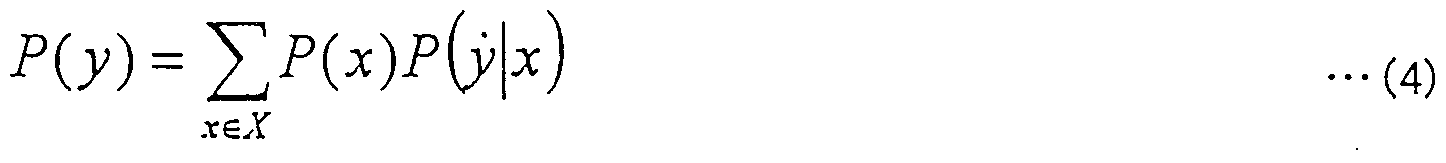
- the probability P (y) of receiving the sequence y is Becomes Now, the sign ⁇ ⁇ of the sign X is finite, and for all X, ⁇ (X) ⁇ 0.
- the received sequence y without error starts from the root of the code tree and always reaches the leaf.
- the received sequence y may start or be received not only at the leaves of the code tree but also at the nodes, so the state transition diagram as shown in Fig. 55 Can be expressed as The transition probability t ⁇ for each state is. (6)
- the probability that an error is detected after the i code word is the probability of being detected next in each state after the i-1 code word
- the decoded value determination unit 105 calculates the forward codeword tape 1 13, the backward codeword table 108, the codeword occurrence probability P (X), the error rate ⁇ of the communication channel, and the estimated probability a range F 2 (a) which is present in the range a) and reverse error in the presence of errors in order direction calculates, from the relationship between the error detection position, determining a portion to be discarded.
- a codeword that is originally incorrect is correct.
- a variable-length decoding device and method capable of reducing the number of times of decoding and reducing the influence of errors in the transmission path.
- a coded moving image signal may have many errors in a transmission path such as a wireless communication path. Even when transmitted via the environment, it is possible to reduce the effect on the display screen due to transmission path errors.
- the probability that a codeword that is originally incorrect is correctly corrected and decoded is further reduced. Becomes possible. Industrial applicability
Landscapes
- Engineering & Computer Science (AREA)
- Multimedia (AREA)
- Signal Processing (AREA)
- Theoretical Computer Science (AREA)
- Compression, Expansion, Code Conversion, And Decoders (AREA)
- Compression Or Coding Systems Of Tv Signals (AREA)
- Error Detection And Correction (AREA)
Description


Claims
Priority Applications (10)
| Application Number | Priority Date | Filing Date | Title |
|---|---|---|---|
| US09/319,160 US6829299B1 (en) | 1997-10-02 | 1998-10-02 | Variable length decoder and decoding method |
| CA 2273169 CA2273169C (en) | 1997-10-02 | 1998-10-02 | Variable length decoder and decoding method |
| EP98945588A EP0966107A4 (en) | 1997-10-02 | 1998-10-02 | ENCODER FOR VARIABLE LENGTH WORDS AND DECODING METHOD |
| BR9806295A BR9806295A (pt) | 1997-10-02 | 1998-10-02 | Aparelho de decodificação e método de decodificação de comprimento variável |
| AU92826/98A AU726301B2 (en) | 1997-10-02 | 1998-10-02 | Variable-length decoding apparatus and decoding method |
| NO19992619A NO992619L (no) | 1997-10-02 | 1999-06-01 | Variabellengde-dekoder og fremgangsmate ved dekoding |
| US10/957,733 US7236530B2 (en) | 1997-10-02 | 2004-10-05 | Variable-length decoding apparatus and decoding method |
| US10/974,704 US7136416B2 (en) | 1997-10-02 | 2004-10-28 | Variable-length decoding apparatus and decoding method |
| US10/974,878 US7203239B2 (en) | 1997-10-02 | 2004-10-28 | Variable-length decoding apparatus and decoding method |
| US11/730,495 US20070183506A1 (en) | 1997-10-02 | 2007-04-02 | Variable-length decoding apparatus and decoding method |
Applications Claiming Priority (4)
| Application Number | Priority Date | Filing Date | Title |
|---|---|---|---|
| JP9/269916 | 1997-10-02 | ||
| JP26991697 | 1997-10-02 | ||
| JP10/189317 | 1998-07-03 | ||
| JP18931798A JP3884172B2 (ja) | 1997-10-02 | 1998-07-03 | 可変長復号化装置および復号化方法 |
Related Child Applications (4)
| Application Number | Title | Priority Date | Filing Date |
|---|---|---|---|
| US09319160 A-371-Of-International | 1998-10-02 | ||
| US10/957,733 Continuation US7236530B2 (en) | 1997-10-02 | 2004-10-05 | Variable-length decoding apparatus and decoding method |
| US10/974,704 Continuation US7136416B2 (en) | 1997-10-02 | 2004-10-28 | Variable-length decoding apparatus and decoding method |
| US10/974,878 Continuation US7203239B2 (en) | 1997-10-02 | 2004-10-28 | Variable-length decoding apparatus and decoding method |
Publications (1)
| Publication Number | Publication Date |
|---|---|
| WO1999018674A1 true WO1999018674A1 (en) | 1999-04-15 |
Family
ID=26505412
Family Applications (1)
| Application Number | Title | Priority Date | Filing Date |
|---|---|---|---|
| PCT/JP1998/004460 WO1999018674A1 (en) | 1997-10-02 | 1998-10-02 | Variable length decoder and decoding method |
Country Status (10)
| Country | Link |
|---|---|
| US (5) | US6829299B1 (ja) |
| EP (1) | EP0966107A4 (ja) |
| JP (1) | JP3884172B2 (ja) |
| KR (1) | KR100334690B1 (ja) |
| CN (1) | CN1153353C (ja) |
| AU (1) | AU726301B2 (ja) |
| BR (1) | BR9806295A (ja) |
| CA (1) | CA2273169C (ja) |
| NO (1) | NO992619L (ja) |
| WO (1) | WO1999018674A1 (ja) |
Cited By (1)
| Publication number | Priority date | Publication date | Assignee | Title |
|---|---|---|---|---|
| DE19937456A1 (de) * | 1999-08-07 | 2001-02-15 | Bosch Gmbh Robert | Rechner zur Datenverarbeitung und Verfahren zur Datenverarbeitung in einem Rechner |
Families Citing this family (44)
| Publication number | Priority date | Publication date | Assignee | Title |
|---|---|---|---|---|
| JP3884172B2 (ja) * | 1997-10-02 | 2007-02-21 | 株式会社東芝 | 可変長復号化装置および復号化方法 |
| TW533738B (en) * | 2000-10-31 | 2003-05-21 | Matsushita Electric Ind Co Ltd | Received information record/regenerate method and received information record/regenerate device |
| US7215360B2 (en) * | 2001-04-06 | 2007-05-08 | Triveni Digital, Inc. | Error propagation tree technology |
| JP3931595B2 (ja) * | 2001-07-10 | 2007-06-20 | 株式会社日立製作所 | データ修正装置及びデータ修正方法 |
| JP2004537911A (ja) * | 2001-07-27 | 2004-12-16 | コーニンクレッカ フィリップス エレクトロニクス エヌ ヴィ | 信号の符号化 |
| JP3775265B2 (ja) * | 2001-08-16 | 2006-05-17 | ソニー株式会社 | 信号処理装置および方法、記録再生装置および方法、ならびに、再生装置および方法 |
| WO2003032497A1 (fr) * | 2001-10-03 | 2003-04-17 | Sony Corporation | Procede de codage et de decodage |
| DE10219133B4 (de) * | 2002-04-29 | 2007-02-22 | Fraunhofer-Gesellschaft zur Förderung der angewandten Forschung e.V. | Vorrichtung und Verfahren zum Verschleiern eines Fehlers |
| US7428684B2 (en) | 2002-04-29 | 2008-09-23 | Fraunhofer-Gesellschaft Zur Forderung Der Angewandten Forschung E.V. | Device and method for concealing an error |
| KR100585710B1 (ko) * | 2002-08-24 | 2006-06-02 | 엘지전자 주식회사 | 가변길이 동영상 부호화 방법 |
| ATE543179T1 (de) * | 2002-09-04 | 2012-02-15 | Microsoft Corp | Entropische kodierung mittels anpassung des kodierungsmodus zwischen niveau- und lauflängenniveau-modus |
| US7433824B2 (en) * | 2002-09-04 | 2008-10-07 | Microsoft Corporation | Entropy coding by adapting coding between level and run-length/level modes |
| US7602850B2 (en) * | 2003-12-19 | 2009-10-13 | Intel Corporation | Content adaptive variable length coding (CAVLC) decoding |
| US20060218459A1 (en) * | 2004-08-13 | 2006-09-28 | David Hedberg | Coding systems and methods |
| US7698623B2 (en) * | 2004-08-13 | 2010-04-13 | David Hedberg | Systems and methods for decreasing latency in a digital transmission system |
| US20060059411A1 (en) * | 2004-09-16 | 2006-03-16 | Sony Corporation And Sony Electronics, Inc. | Method and system for increasing channel coding gain |
| PT1797697T (pt) * | 2004-10-05 | 2021-04-30 | Vectormax Corp | Método e sistema para difusão de dados multimédia |
| US7650031B2 (en) * | 2004-11-23 | 2010-01-19 | Microsoft Corporation | Method and system for detecting black frames in a sequence of frames |
| US7684981B2 (en) | 2005-07-15 | 2010-03-23 | Microsoft Corporation | Prediction of spectral coefficients in waveform coding and decoding |
| US7693709B2 (en) * | 2005-07-15 | 2010-04-06 | Microsoft Corporation | Reordering coefficients for waveform coding or decoding |
| US7933337B2 (en) | 2005-08-12 | 2011-04-26 | Microsoft Corporation | Prediction of transform coefficients for image compression |
| EP1972154A4 (en) | 2006-01-09 | 2014-11-19 | Lg Electronics Inc | INTERLAYER PREDICTION METHOD FOR VIDEO SIGNAL |
| US8848789B2 (en) * | 2006-03-27 | 2014-09-30 | Qualcomm Incorporated | Method and system for coding and decoding information associated with video compression |
| US8184710B2 (en) | 2007-02-21 | 2012-05-22 | Microsoft Corporation | Adaptive truncation of transform coefficient data in a transform-based digital media codec |
| BRPI0808489A2 (pt) * | 2007-03-14 | 2014-07-15 | Nippon Telegraph & Telephone | Método e aparelho de controle de quantização, programa para os mesmos, e meio de armazenamento que armazena o programa |
| CN101632308B (zh) * | 2007-03-14 | 2011-08-03 | 日本电信电话株式会社 | 编码比特率控制方法和装置 |
| CN101682775B (zh) * | 2007-03-14 | 2015-04-01 | 日本电信电话株式会社 | 运动矢量搜索方法和装置 |
| EP2120461B1 (en) * | 2007-03-14 | 2011-07-06 | Nippon Telegraph and Telephone Corporation | Code quantity estimating method and device, their program, and recording medium |
| US8233537B2 (en) * | 2007-03-19 | 2012-07-31 | Texas Instruments Incorporated | Efficient implementation of H.264 4 by 4 intra prediction on a VLIW processor |
| KR101086435B1 (ko) * | 2007-03-29 | 2011-11-25 | 삼성전자주식회사 | 영상 데이터 스트림의 에러 검출 방법 및 그 장치 |
| US7908463B2 (en) * | 2007-06-26 | 2011-03-15 | Globalfoundries Inc. | Immediate and displacement extraction and decode mechanism |
| US7818542B2 (en) * | 2007-07-10 | 2010-10-19 | Globalfoundries Inc. | Method and apparatus for length decoding variable length instructions |
| US8013765B1 (en) * | 2008-05-01 | 2011-09-06 | Cavium, Inc. | Modular scaleable processing engine for accelerating variable length coding |
| US8179974B2 (en) | 2008-05-02 | 2012-05-15 | Microsoft Corporation | Multi-level representation of reordered transform coefficients |
| US8406307B2 (en) | 2008-08-22 | 2013-03-26 | Microsoft Corporation | Entropy coding/decoding of hierarchically organized data |
| FR2951896A1 (fr) * | 2009-10-23 | 2011-04-29 | France Telecom | Procede d'encapsulation de sous-flux de donnees, procede de desencapsulation et programmes d'ordinateur correspondants |
| WO2012030262A1 (en) * | 2010-09-03 | 2012-03-08 | Telefonaktiebolaget Lm Ericsson (Publ) | Co-compression and co-decompression of data values |
| KR20140084294A (ko) * | 2011-10-27 | 2014-07-04 | 엘에스아이 코포레이션 | 복소 지수 비선형 함수와 함께 명령어를 갖는 디지털 처리 |
| CN105323583B (zh) | 2014-06-13 | 2019-11-15 | 财团法人工业技术研究院 | 编码方法、解码方法、编解码系统、编码器与解码器 |
| CN109257136A (zh) * | 2017-07-12 | 2019-01-22 | 中国科学院大学 | 联合信源信道与安全的jpeg2000算术码的双向编译码方法 |
| JP2019165365A (ja) * | 2018-03-20 | 2019-09-26 | 株式会社東芝 | 信号処理装置 |
| US11152953B2 (en) * | 2020-02-28 | 2021-10-19 | Qualcomm Incorporated | Error detection for a wireless channel |
| CN112422984B (zh) * | 2020-10-26 | 2023-02-28 | 眸芯科技(上海)有限公司 | 多核解码系统的码流预处理装置、系统及方法 |
| WO2023147860A1 (en) * | 2022-02-03 | 2023-08-10 | Dream Chip Technologies Gmbh | Gradient based pixel by pixel image spatial prediction |
Citations (3)
| Publication number | Priority date | Publication date | Assignee | Title |
|---|---|---|---|---|
| JPH05252055A (ja) * | 1992-03-06 | 1993-09-28 | Mitsubishi Electric Corp | 符号化装置および復号化装置 |
| JPH05300027A (ja) * | 1992-04-17 | 1993-11-12 | Kokusai Denshin Denwa Co Ltd <Kdd> | 可逆可変長符号化方式 |
| JPH08340258A (ja) * | 1995-04-14 | 1996-12-24 | Toshiba Corp | 可変長符号化/復号化装置 |
Family Cites Families (11)
| Publication number | Priority date | Publication date | Assignee | Title |
|---|---|---|---|---|
| JPH02301280A (ja) | 1989-05-15 | 1990-12-13 | Nec Corp | 動画像信号の符号化・復号化方式 |
| US5488418A (en) | 1991-04-10 | 1996-01-30 | Mitsubishi Denki Kabushiki Kaisha | Encoder and decoder |
| US5226082A (en) * | 1992-07-02 | 1993-07-06 | At&T Bell Laboratories | Variable length decoder |
| KR100396971B1 (ko) * | 1994-11-29 | 2003-11-03 | 산요덴키가부시키가이샤 | 인코드된비디오데이터의에러검출및처리기능을구비한비디오디코더 |
| EP1802139A2 (en) | 1995-03-15 | 2007-06-27 | Kabushiki Kaisha Toshiba | Moving picture coding and/or decoding systems |
| US6104754A (en) * | 1995-03-15 | 2000-08-15 | Kabushiki Kaisha Toshiba | Moving picture coding and/or decoding systems, and variable-length coding and/or decoding system |
| US6415398B1 (en) * | 1995-09-29 | 2002-07-02 | Kabushiki Kaisha Toshiba | Coding system and decoding system |
| US5778191A (en) * | 1995-10-26 | 1998-07-07 | Motorola, Inc. | Method and device for error control of a macroblock-based video compression technique |
| EP0861001B1 (en) | 1997-02-07 | 2012-05-23 | Texas Instruments Incorporated | Error resilient video encoding |
| JP3884172B2 (ja) * | 1997-10-02 | 2007-02-21 | 株式会社東芝 | 可変長復号化装置および復号化方法 |
| JP2000032393A (ja) * | 1998-07-09 | 2000-01-28 | Sony Corp | 画像情報処理装置および方法、並びに提供媒体 |
-
1998
- 1998-07-03 JP JP18931798A patent/JP3884172B2/ja not_active Expired - Fee Related
- 1998-10-02 EP EP98945588A patent/EP0966107A4/en not_active Withdrawn
- 1998-10-02 CN CNB98802246XA patent/CN1153353C/zh not_active Expired - Lifetime
- 1998-10-02 CA CA 2273169 patent/CA2273169C/en not_active Expired - Lifetime
- 1998-10-02 AU AU92826/98A patent/AU726301B2/en not_active Expired
- 1998-10-02 KR KR1019997004860A patent/KR100334690B1/ko not_active IP Right Cessation
- 1998-10-02 BR BR9806295A patent/BR9806295A/pt not_active Application Discontinuation
- 1998-10-02 US US09/319,160 patent/US6829299B1/en not_active Expired - Lifetime
- 1998-10-02 WO PCT/JP1998/004460 patent/WO1999018674A1/ja active IP Right Grant
-
1999
- 1999-06-01 NO NO19992619A patent/NO992619L/no not_active Application Discontinuation
-
2004
- 2004-10-05 US US10/957,733 patent/US7236530B2/en not_active Expired - Fee Related
- 2004-10-28 US US10/974,704 patent/US7136416B2/en not_active Expired - Fee Related
- 2004-10-28 US US10/974,878 patent/US7203239B2/en not_active Expired - Fee Related
-
2007
- 2007-04-02 US US11/730,495 patent/US20070183506A1/en not_active Abandoned
Patent Citations (3)
| Publication number | Priority date | Publication date | Assignee | Title |
|---|---|---|---|---|
| JPH05252055A (ja) * | 1992-03-06 | 1993-09-28 | Mitsubishi Electric Corp | 符号化装置および復号化装置 |
| JPH05300027A (ja) * | 1992-04-17 | 1993-11-12 | Kokusai Denshin Denwa Co Ltd <Kdd> | 可逆可変長符号化方式 |
| JPH08340258A (ja) * | 1995-04-14 | 1996-12-24 | Toshiba Corp | 可変長符号化/復号化装置 |
Non-Patent Citations (5)
| Title |
|---|
| CHUJOH T., ET AL.: "REVERSIBLE CODE AND ITS APPLICATION TO ERROR-TOLERANT VIDEO CODING", THE TRANSACTIONS OF THE IEICE, NEW YORK, NY, US, vol. J80A., no. 03., 1 March 1997 (1997-03-01), US, pages 532 - 541., XP002920230 * |
| FRAENKEL A. S., KLEIN S. T.: "BIDIRECTIONAL HUFFMAN CODING.", COMPUTER JOURNAL., OXFORD UNIVERSITY PRESS, SURREY., GB, vol. 33., no. 04., 1 August 1990 (1990-08-01), GB, pages 296 - 307., XP000159500, ISSN: 0010-4620, DOI: 10.1093/comjnl/33.4.296 * |
| KIKUCHI Y., ET AL.: "ERROR RESILIENT MOTION PICTURE CODING FOR MOBILE VIDEO COMMUNICATION.", EIZO JOHO MEDIA GAKKAISHI - THE JOURNAL OF THE INSTITUTE OF IMAGE INFORMATION AND TELEVISION ENGINEERS, EIZO JOHO MEDIA GAKKA, JP, vol. 51., no. 10., 1 January 1997 (1997-01-01), JP, pages 1722 - 1729., XP002920231, ISSN: 1342-6907 * |
| See also references of EP0966107A4 * |
| TAKISHIMA T., WADA M., MURAKAMI H.: "REVERSIBLE VARIABLE LENGTH CODES.", IEEE TRANSACTIONS ON COMMUNICATIONS., IEEE SERVICE CENTER, PISCATAWAY, NJ. USA., vol. 43., no. 02/04, PART 01., 1 February 1995 (1995-02-01), PISCATAWAY, NJ. USA., pages 158 - 162., XP000506544, ISSN: 0090-6778, DOI: 10.1109/26.380026 * |
Cited By (2)
| Publication number | Priority date | Publication date | Assignee | Title |
|---|---|---|---|---|
| DE19937456A1 (de) * | 1999-08-07 | 2001-02-15 | Bosch Gmbh Robert | Rechner zur Datenverarbeitung und Verfahren zur Datenverarbeitung in einem Rechner |
| DE19937456C2 (de) * | 1999-08-07 | 2001-06-13 | Bosch Gmbh Robert | Rechner zur Datenverarbeitung und Verfahren zur Datenverarbeitung in einem Rechner |
Also Published As
| Publication number | Publication date |
|---|---|
| US20070183506A1 (en) | 2007-08-09 |
| NO992619D0 (no) | 1999-06-01 |
| CN1246990A (zh) | 2000-03-08 |
| US7236530B2 (en) | 2007-06-26 |
| CA2273169C (en) | 2004-06-08 |
| US6829299B1 (en) | 2004-12-07 |
| KR100334690B1 (ko) | 2002-04-27 |
| AU9282698A (en) | 1999-04-27 |
| US20050084019A1 (en) | 2005-04-21 |
| CA2273169A1 (en) | 1999-04-15 |
| US20050041741A1 (en) | 2005-02-24 |
| NO992619L (no) | 1999-08-02 |
| KR20000069256A (ko) | 2000-11-25 |
| US7203239B2 (en) | 2007-04-10 |
| JPH11168393A (ja) | 1999-06-22 |
| EP0966107A4 (en) | 2000-12-13 |
| AU726301B2 (en) | 2000-11-02 |
| CN1153353C (zh) | 2004-06-09 |
| JP3884172B2 (ja) | 2007-02-21 |
| EP0966107A1 (en) | 1999-12-22 |
| US7136416B2 (en) | 2006-11-14 |
| US20050066318A1 (en) | 2005-03-24 |
| BR9806295A (pt) | 2000-04-11 |
Similar Documents
| Publication | Publication Date | Title |
|---|---|---|
| WO1999018674A1 (en) | Variable length decoder and decoding method | |
| JP3657971B2 (ja) | 復号化方法及び装置 | |
| JP3612314B2 (ja) | 可変長符号化方法及び装置 | |
| JP3869342B2 (ja) | 可変長復号化方法及び装置 | |
| JP2006217613A (ja) | 可変長復号化装置 | |
| JP2001308717A (ja) | 可変長復号化方法及び装置 |
Legal Events
| Date | Code | Title | Description |
|---|---|---|---|
| WWE | Wipo information: entry into national phase |
Ref document number: 98802246.X Country of ref document: CN |
|
| AK | Designated states |
Kind code of ref document: A1 Designated state(s): AU BR CA CN KR MX NO SG US VN |
|
| AL | Designated countries for regional patents |
Kind code of ref document: A1 Designated state(s): CH DE ES FR GB IT NL SE |
|
| WWE | Wipo information: entry into national phase |
Ref document number: 92826/98 Country of ref document: AU |
|
| ENP | Entry into the national phase |
Ref document number: 2273169 Country of ref document: CA |
|
| WWE | Wipo information: entry into national phase |
Ref document number: PA/a/1999/005051 Country of ref document: MX |
|
| WWE | Wipo information: entry into national phase |
Ref document number: 09319160 Country of ref document: US Ref document number: 1019997004860 Country of ref document: KR |
|
| WWE | Wipo information: entry into national phase |
Ref document number: 1998945588 Country of ref document: EP |
|
| 121 | Ep: the epo has been informed by wipo that ep was designated in this application | ||
| WWE | Wipo information: entry into national phase |
Ref document number: 1199900543 Country of ref document: VN |
|
| WWP | Wipo information: published in national office |
Ref document number: 1998945588 Country of ref document: EP |
|
| WWP | Wipo information: published in national office |
Ref document number: 1019997004860 Country of ref document: KR |
|
| WWG | Wipo information: grant in national office |
Ref document number: 92826/98 Country of ref document: AU |
|
| WWG | Wipo information: grant in national office |
Ref document number: 1019997004860 Country of ref document: KR |