WO1994018351A1 - Nitrogen-containing hard sintered alloy - Google Patents
Nitrogen-containing hard sintered alloy Download PDFInfo
- Publication number
- WO1994018351A1 WO1994018351A1 PCT/JP1994/000158 JP9400158W WO9418351A1 WO 1994018351 A1 WO1994018351 A1 WO 1994018351A1 JP 9400158 W JP9400158 W JP 9400158W WO 9418351 A1 WO9418351 A1 WO 9418351A1
- Authority
- WO
- WIPO (PCT)
- Prior art keywords
- phase
- alloy
- hard
- nitrogen
- less
- Prior art date
Links
Classifications
-
- C—CHEMISTRY; METALLURGY
- C22—METALLURGY; FERROUS OR NON-FERROUS ALLOYS; TREATMENT OF ALLOYS OR NON-FERROUS METALS
- C22C—ALLOYS
- C22C29/00—Alloys based on carbides, oxides, nitrides, borides, or silicides, e.g. cermets, or other metal compounds, e.g. oxynitrides, sulfides
- C22C29/02—Alloys based on carbides, oxides, nitrides, borides, or silicides, e.g. cermets, or other metal compounds, e.g. oxynitrides, sulfides based on carbides or carbonitrides
- C22C29/04—Alloys based on carbides, oxides, nitrides, borides, or silicides, e.g. cermets, or other metal compounds, e.g. oxynitrides, sulfides based on carbides or carbonitrides based on carbonitrides
-
- C—CHEMISTRY; METALLURGY
- C22—METALLURGY; FERROUS OR NON-FERROUS ALLOYS; TREATMENT OF ALLOYS OR NON-FERROUS METALS
- C22C—ALLOYS
- C22C29/00—Alloys based on carbides, oxides, nitrides, borides, or silicides, e.g. cermets, or other metal compounds, e.g. oxynitrides, sulfides
- C22C29/16—Alloys based on carbides, oxides, nitrides, borides, or silicides, e.g. cermets, or other metal compounds, e.g. oxynitrides, sulfides based on nitrides
-
- B—PERFORMING OPERATIONS; TRANSPORTING
- B22—CASTING; POWDER METALLURGY
- B22F—WORKING METALLIC POWDER; MANUFACTURE OF ARTICLES FROM METALLIC POWDER; MAKING METALLIC POWDER; APPARATUS OR DEVICES SPECIALLY ADAPTED FOR METALLIC POWDER
- B22F2998/00—Supplementary information concerning processes or compositions relating to powder metallurgy
Definitions
- the present invention relates to a nitrogen-containing sintered hard alloy having excellent thermal shock resistance, wear resistance and toughness, and particularly exhibiting extremely excellent performance when applied to a cutting tool.
- a sintered hard K alloy containing nitrogen combined with a metal consisting of Ni and C0 has been put into practical use as a cutting tool. ing.
- This nitrogen-containing sintered hard alloy has a hard phase that is remarkably finer than conventional sintered hard alloys that do not contain nitrogen, greatly improving high-temperature creep resistance. These are widely used as cutting tools along with the so-called cemented carbide.
- this nitrogen-containing sintered hard alloy has the following characteristics: (1) The thermal conductivity of the carbonitride of Ti, which is the main component, is significantly smaller than that of WC, which is the main component of the cemented carbide. The thermal conductivity is about 1 to 2. 2 The coefficient of thermal expansion of the sintered hard alloy containing nitrogen is also 1.3 times that of cemented carbide, depending on the characteristic value of the main component. For example, the resistance to thermal shock is reduced. For this reason, sufficient reliability is obtained, especially for cutting under severe thermal shock conditions, such as milling, cutting with a square bar, and arrogant cutting in a wet process where the cutting depth varies greatly. It was not used at the moment.
- the present inventors have conducted detailed research on the cutting phenomena such as temperature distribution and stress distribution in the tool in various types of cutting and detailed research on the arrangement of material components in the tool. Obtained. Due to the high thermal conductivity of cemented carbide, it rapidly diffuses through the inside of the high-gap tool that forms on the tool surface during cutting, so that the surface does not become hot and the cutting slips suddenly. Even if the high-temperature portion is suddenly exposed to water-soluble cutting oil and suddenly cooled, the small thermal expansion coefficient also has an effect, and the tensile stress on the surface layer is unlikely to remain.
- sintered nitrogen-containing hard alloys containing Ti as the main component have low thermal conductivity.
- -Heat is not easily diffused from the part where the cutting edge of the cutting edge, which is the hottest, is easy to hit.
- the surface has a steep temperature gradient, such as the surface is hot and the temperature drops rapidly inside. ing.
- the low temperature of the alloy is prone to significant chipping.
- a so-called temperature gradient reversal phenomenon occurs in which only the outer surface is cooled and the area immediately below it is kept hot, and the coefficient of thermal expansion is large.
- the nitrogen-containing sintered hard alloy of the present invention arranges a large amount of T i component in the extreme surface layer which determines the properties of the cutting surface of the tool, and has a high toughness N i or A large number of bonding metals such as C 0 are arranged to increase the strength just below the cutting edge. Since the Ni / C0-enriched layer has a large thermal expansion coefficient, it also has the effect of generating a compressive stress in the surface layer when cooling after sintering or when the cutting tool is separated. In addition, W, which is an essential component of the hard phase, is enriched from the surface to the inside.
- the main heat conduction medium of the nitrogen-containing sintered hard alloy is considered to be the binder phase, but the hard phase also contributes to the internal heat conduction by enriching W.
- the reason why the binder phase is reduced and the hard phase is added inside the binder phase-enriched layer is to more effectively exhibit the heat conduction improving effect.
- the highest part of the amount of the binder phase exists in the depth range where the amount of the binder metal phase is 3 m or more and 500 m or less from the surface. 1.1 to 4 times the amount, returns to the average amount of bonded phase of the entire alloy by 800 m in depth, and the amount of bonded phase on the surface is 0.9 times that of the highest bonded phase. The following is assumed.
- the depth of 800 m is used to prevent the thermal conductivity from lowering and to improve the plastic deformation resistance of the tool during cutting.
- T i and T a, N bs Z r which have the same effect of improving wear resistance to steel cutting, are enriched in the surface, and instead, W and M 0, which have little effect, are reduced.
- W is not present as WC particles on the surface. It has been found that even if is present, it is sufficient that the content is not more than 0.1% by volume.
- the binder phase enriched region is necessary to increase the tool strength and to have the effect of generating a compressive stress in the surface layer when cooling after sintering or when the cutting tool is detached. If it is less than 3, the wear resistance of the tool will be poor, and if it exceeds 500 m, the effect of applying compressive stress to the surface will not be sufficiently exhibited. If the ratio of the highest amount of binder phase to the average amount of binder phase is less than 1.1 times, the desired strength improvement effect cannot be obtained, and if it exceeds 4 times, plastic deformation will occur during cutting or the inside will become too hard g. It is not preferable because the strength is insufficient.
- the surface must have abrasion resistance and be subjected to compressive stress due to its lower coefficient of thermal expansion than the inside.Therefore, if the maximum binder phase ratio exceeds 0.9 times, these The required effect cannot be obtained.
- the surface must have abrasion resistance, and it is necessary to enrich Ti, Nb, and Zr, which have Ti and similar abrasion resistance improving effects, on the surface. If the average ratio is less than 1.01, the required wear resistance cannot be obtained. Particularly, Ta and Nb are preferable because they can also increase high-temperature oxidation resistance. In addition, this enrichment has the effect that the properties of the machined surface are also extremely excellent.
- the form of W enrichment in the hard phase from the surface to the inside of the alloy may be present as WC particles, or a complex carbonitride solid solution May be W-rich.
- the solid phase of the W-rich may be partially present as a form of the hard phase, or may be larger than the surface texture, and the center is white in the scanning electron microscope and the periphery is white.
- white core particles white portions are W-rich portions and gray portions are W-poor portions
- the desired effect of improving heat conduction characteristics and strength can be obtained. can get.
- the ranges of 0.5 ⁇ X ⁇ 0.95 and 0.05 ⁇ y ⁇ 0.5 are set to maintain wear resistance and heat resistance. If the content is outside these ranges, the wear resistance and heat resistance decrease, so that the object of the present invention cannot be achieved.
- the present inventors have conducted various studies and researches on means for improving the heat shock resistance and also improving the wear resistance and toughness.
- a method for imparting compressive residual stress to the vicinity of the surface of a nitrogen-containing sintered hard alloy is described. Was found to be the most effective. Due to the change in the thermal environment, tensile stress acts on the vicinity of the surface of the nitrogen-containing sintered hard alloy, as described above. Thermal cracks) occur and the strength of the nitrogen-containing sinter hardened S alloy decreases, eventually leading to fracture. This means that improving the power resistance of the nitrogen-containing sintered hard alloy leads to an improvement in thermal shock resistance.
- the inventors have concluded that it is most effective to apply compressive residual stress to the surface of the nitrogen-containing sintered hard alloy.
- the nitrogen-containing sintered hard alloy of the present invention improves the thermal shock resistance by imparting the compressive residual stress. Compared with conventional nitrogen-containing sintered hard alloys, it has become possible to significantly improve wear resistance and toughness.
- the nitrogen-containing sintered hard alloy of the present invention is heated under vacuum, and the atmosphere during sintering (1400 to 1550 t) is a carburizing atmosphere or a nitriding atmosphere, A structure containing a hard phase containing a large amount of Ti in the vicinity of the surface and a small amount or a small amount of the binder phase is formed. It is characterized by a structure that increases the volume ratio occupied. By increasing the cooling rate to 0.05 to 0.8 times the conventional cooling rate, the binder phase gradually and suddenly increases from directly below the surface to the inside, and as a result, the desired compressive residual stress is increased. It can be applied to the vicinity.
- the portion near the surface has a hard phase mainly composed of T i (or ; 'Metal phase), it exhibits more ft: wear resistance than conventional nitrogen-containing sintered hard alloys, and is rich in binder phase just below the surface. Therefore, it has excellent toughness.
- the metal component or the metal component and WC may be slightly stained on the surface, but since the thickness is 5 or less, the cutting performance is not affected.
- the residual stress value is 1.01 times higher than the compressive residual stress value on the outermost surface, it has an effect on crack resistance ⁇ spreadability. Moreover, when the value is 4 O kg / optionally 2 or more, it shows crack propagation resistance comparable to that of cemented carbide.
- the compressive residual stress value on the outermost surface is low, and the thermal shock resistance is reduced.
- a hard and brittle layer having a width of 100 m or more is formed in the vicinity of the surface, resulting in a decrease in toughness.
- the area where the combined phase is 5% by volume or less is 1 m or more from the surface. If it is less than m, it is possible to obtain excellent wear resistance without lowering the toughness.
- the binder phase is absent or less than 1% by volume and its region width is 1 m or more and 50 or less (see FIG. 7).
- the inventors have studied the correlation between the compressive residual stress and the distribution of the binder phase from the surface toward the inside, and as a result, the larger the concentration gradient (increment per unit distance) of the metal binder phase toward the inside, the larger the value. It was found that the compressive residual stress in the vicinity of the starting point of the increase in the binder phase increases as the binder phase increases (see Fig. 7).
- the maximum concentration gradient of the binder phase (increase in the binder phase per m) must be 0.055% by volume or more toward the inside. It turned out that we had to do that.
- the volume% of the metal binder phase is 5 volumes below the surface side from the start point of the increase in the binder phase, and the width of the region maintaining the structure is 1 ⁇ m or more and 100 m or less.
- the toughness inside By allowing more WC particles to exist inside the surface portion than in the surface portion, it becomes possible to improve the toughness inside while maintaining the wear resistance inherent in Ti at the surface portion. From the viewpoint of abrasion resistance, it is desirable to reduce the WC content to 5% by volume or less in a region within 50 m from the surface. In addition, the presence of WC particles promotes the improvement of thermal conductivity, the thermal shock resistance is improved as compared with a nitrogen-containing sintered hard alloy without WC particles, and the fracture resistance is improved by improving the Young's modulus. Is very good.
- a cutting tool cutting under particularly severe conditions of thermal shock, such as milling with a lathe of a square or a square bar, or a wet cutting method in which the incision greatly fluctuates. This has the effect of being able to provide extremely reliable nitrogen-containing sintered hard alloys for arrogant cutting.
- the nitrogen-containing sintered hard alloy of the present invention has the same thermal shock resistance as a cemented carbide, it can be used not only as a cutting tool but also as a wear-resistant member. Simple light
- FIG. 1 shows the composition distribution in the depth direction from the surface of Sample 1 in Example 1 of the present invention.
- FIG. 2 is a diagram showing a composition distribution in the depth direction from the surface of sample 2 in Example 1 of the present invention.
- FIG. 3 is a diagram showing a composition distribution in the depth direction from the surface of sample 3 in Example 1 of the present invention.
- FIG. 4 is a diagram showing a composition distribution in the depth direction from the surface of Sample 4 in Example 1 of the present invention.
- FIG. 5 is a diagram showing an example of a distribution state of a binder phase according to the present invention.
- FIG. 6 is a diagram showing a compressive residual stress distribution in the binder phase distribution of FIG.
- FIG. 7 is a diagram showing the relationship between the distribution and intensity of C 0 as a binder phase.
- samples 2 obtained by sintering the same embossed compact under a nitrogen partial pressure of 5 Torr at 1400 and samples identical to those of sample 2 were prepared by some conventional manufacturing methods.
- Sample 3 was cooled at a C0 partial pressure of 200 Torr after sintering, and Sample 4 was cooled at the same nitrogen partial pressure of 1 C0 Torr after sintering as Sample 2.
- Table 2 shows these structures.
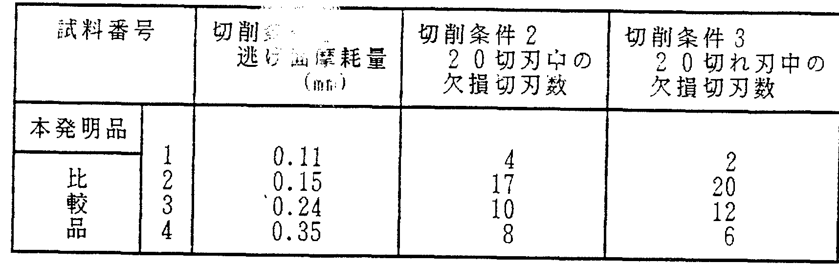
- Table 4 shows the results of the determinations performed together with the nitrogen-containing sintered hard alloys of samples 1 to 4 under the cutting conditions 1 to 3 shown in Table 3.
- Cutting condition 1 Cutting condition 2
- Cutting condition 3 Tool shape CN G432 C Recommended 432 CNMG432
- Notch 1.0 related 2.0 mm fluctuates from 1.5 to 2.0 mm
- Cutting oil Water soluble Not used Water soluble
- Cutting time 15 minutes 30 seconds 15 minutes Judgment Flank wear amount 20 during cutting edge 20 during cutting edge
- samples 7 and 8 with the structure shown in Table 5 were prepared from the same compact. These were evaluated under the cutting conditions shown in Table 6 and the results are shown in Table 7.
- Samples 11 to 13 were also prepared from the same raw material powder and blended so as to have the average amount of the binder phase and the internal hard phase composition (Ti + Nb, W) shown in Table 8.
- Samples 14 to 19 are different structural alloys for comparison using the same compacts as Samples 9 and 10. Table 9 shows the conditions and results of these cutting tests.
- Example 4 with an average particle diameter of 2 m, the white in the outer portion of the cored structure reflected electron microscope image, the core portion appears black (T iabo 4 W 0. 17 ) (Co.
- Powder the 1. 5 ⁇ N i powder and C o powder each 8 5% by weight of m, 8 wt%, after the wet mixing 7% by weight, embossing molding, in a vacuum of 1 0- 2 Torr in 1 2 0 after degassing at 0, 1 4 5 0 1 hour sintering after sintering at ° C in a nitrogen gas partial pressure 1 O Torr, C 0 2 cooled alloy sample 2 0, T i (CN), Sample 21 was prepared by mixing, mixing, and sintering TaC, WC, NbC, Co, and Ni so as to have the same composition as sample 20.
- Strip 1.5mm fluctuates from 1.5 to 0.1mm
- the average composition shown in Table 12 was obtained using Ta / C powder of 5 / um, WC powder of 4 / um, ZrC powder of 2 m, Ni powder and Co powder of 1.5 m. Structured alloy made 1 3 average
- Table 2 shows the characteristics of each alloy sample.
- the present invention 25 0.15 0
- Table 15 shows the characteristics of each alloy sample.
- Strip depth 1. Fluctuates from 1.5 mm to 0.2 mm
- (C) A powder of (Tio.6, W0.2, NbO.2) (CO.7.NO.3) with an average particle size of 1.5 tim is 82% by weight, and an average particle size. 1.5 m of Ni powder and 9 wt% of C 0 powder
- Table 16 shows the compressive residual stress values of Samples A-1 to A-5.
- the compressive residual stress was measured by an X-ray residual stress measurement method, and a Young's modulus of 460,000 and a poson ratio of 0.23 were used in calculating the stress value. Residual compressive stress 4?
- Table 4 shows the distribution of the binder phase in samples B-1 to B_8.
- Table 19 shows the distribution of the binder phase in samples B-1 to B_8.
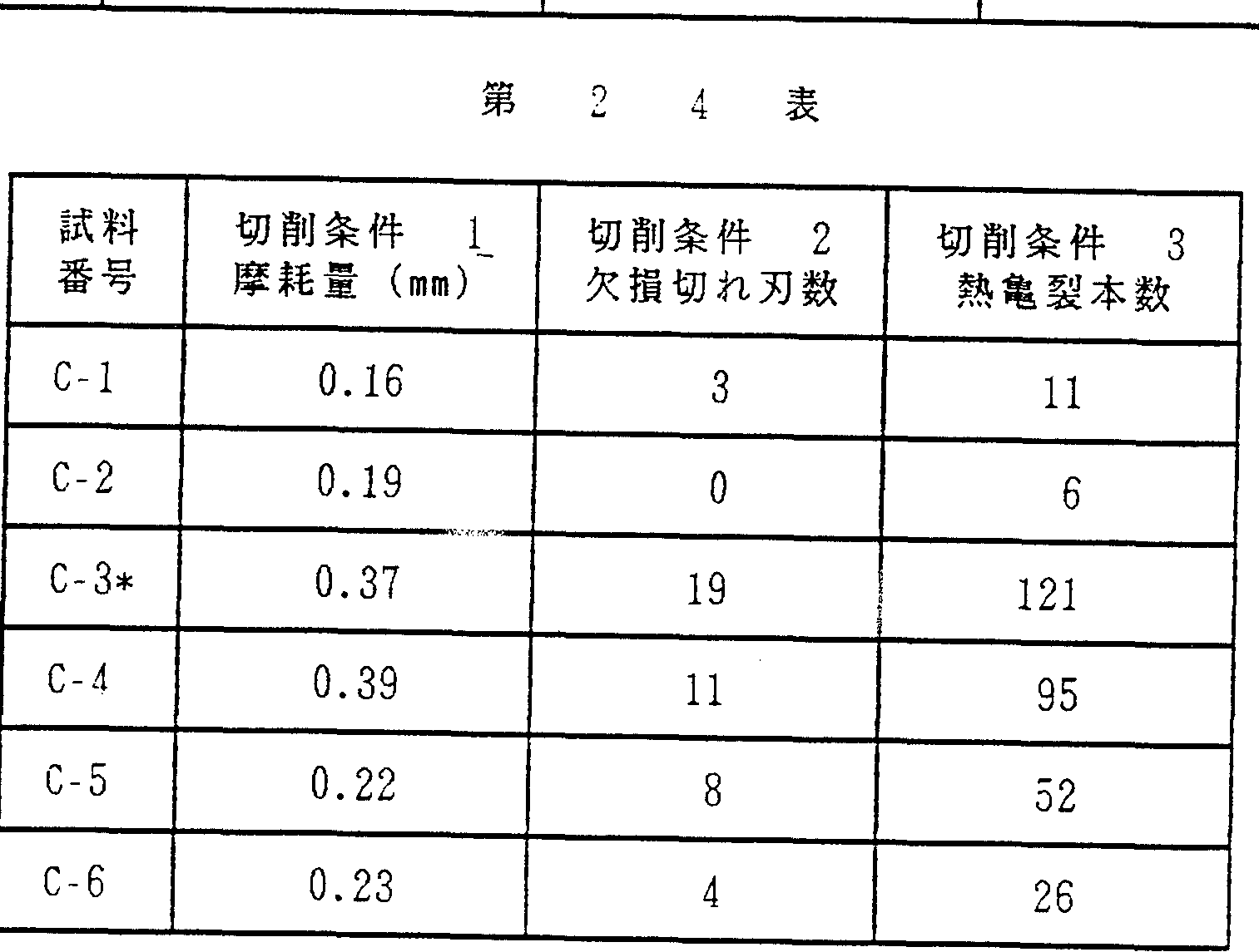
- Table 22 shows the compressive residual stress values and the distribution of the binder phase of sample C-1C-6. ⁇ 9 0 1
Abstract
Description


Claims
Priority Applications (3)
| Application Number | Priority Date | Filing Date | Title |
|---|---|---|---|
| EP94905840A EP0635580A4 (en) | 1993-02-05 | 1994-02-03 | Nitrogen-containing hard sintered alloy. |
| US08/313,222 US5577424A (en) | 1993-02-05 | 1994-02-03 | Nitrogen-containing sintered hard alloy |
| KR1019940703517A KR950701006A (en) | 1993-02-05 | 1994-10-05 | NITROGEN-CONTAINING HARD SINTERED ALLOY |
Applications Claiming Priority (4)
| Application Number | Priority Date | Filing Date | Title |
|---|---|---|---|
| JP5/18283 | 1993-02-05 | ||
| JP5018283A JP3064722B2 (en) | 1993-02-05 | 1993-02-05 | Nitrogen-containing sintered hard alloy |
| JP5/323917 | 1993-12-22 | ||
| JP32391793A JP3605838B2 (en) | 1993-12-22 | 1993-12-22 | cermet |
Publications (1)
| Publication Number | Publication Date |
|---|---|
| WO1994018351A1 true WO1994018351A1 (en) | 1994-08-18 |
Family
ID=26354938
Family Applications (1)
| Application Number | Title | Priority Date | Filing Date |
|---|---|---|---|
| PCT/JP1994/000158 WO1994018351A1 (en) | 1993-02-05 | 1994-02-03 | Nitrogen-containing hard sintered alloy |
Country Status (6)
| Country | Link |
|---|---|
| US (1) | US5577424A (en) |
| EP (2) | EP0864661B1 (en) |
| KR (2) | KR0143508B1 (en) |
| DE (1) | DE69433214T2 (en) |
| TW (1) | TW291499B (en) |
| WO (1) | WO1994018351A1 (en) |
Families Citing this family (21)
| Publication number | Priority date | Publication date | Assignee | Title |
|---|---|---|---|---|
| US6057046A (en) * | 1994-05-19 | 2000-05-02 | Sumitomo Electric Industries, Ltd. | Nitrogen-containing sintered alloy containing a hard phase |
| EP0822265B1 (en) * | 1994-05-19 | 2001-10-17 | Sumitomo Electric Industries, Ltd. | Nitrogen-containing sintered hard alloy |
| US5710383A (en) * | 1995-11-27 | 1998-01-20 | Takaoka; Hidemitsu | Carbonitride-type cermet cutting tool having excellent wear resistance |
| US6017488A (en) * | 1998-05-11 | 2000-01-25 | Sandvik Ab | Method for nitriding a titanium-based carbonitride alloy |
| DE59803436D1 (en) * | 1997-05-28 | 2002-04-25 | Siemens Ag | METAL CERAMIC GRADIENT MATERIAL, PRODUCT THEREOF AND METHOD FOR PRODUCING A METAL CERAMIC GRADIENT MATERIAL |
| DE19845376C5 (en) * | 1998-07-08 | 2010-05-20 | Widia Gmbh | Hard metal or cermet body |
| US6110603A (en) * | 1998-07-08 | 2000-08-29 | Widia Gmbh | Hard-metal or cermet body, especially for use as a cutting insert |
| ATE221140T1 (en) * | 1998-07-08 | 2002-08-15 | Widia Gmbh | CARBIDE OR CERMET BODY AND METHOD FOR PRODUCING IT |
| DE19907749A1 (en) * | 1999-02-23 | 2000-08-24 | Kennametal Inc | Sintered hard metal body useful as cutter insert or throwaway cutter tip has concentration gradient of stress-induced phase transformation-free face-centered cubic cobalt-nickel-iron binder |
| US6155284A (en) * | 1999-03-17 | 2000-12-05 | Scantlin; Gary | Buckling pin latch actuated safety relief valve |
| WO2002049989A2 (en) | 2000-12-19 | 2002-06-27 | Honda Giken Kogyo Kabushiki Kaisha | Composite material |
| CN100515995C (en) * | 2000-12-19 | 2009-07-22 | 本田技研工业株式会社 | Molding tool formed of gradient composite material and method of producing the same |
| AU2002222612A1 (en) * | 2000-12-19 | 2002-07-01 | Honda Giken Kogyo Kabushiki Kaisha | Machining tool and method of producing the same |
| WO2010013735A1 (en) * | 2008-07-29 | 2010-02-04 | 京セラ株式会社 | Cutting tool |
| CN103282147B (en) * | 2010-12-25 | 2014-10-08 | 京瓷株式会社 | Cutting tool |
| GB201100966D0 (en) * | 2011-01-20 | 2011-03-02 | Element Six Holding Gmbh | Cemented carbide article |
| JP6278232B2 (en) * | 2013-11-01 | 2018-02-14 | 住友電気工業株式会社 | cermet |
| US10144065B2 (en) | 2015-01-07 | 2018-12-04 | Kennametal Inc. | Methods of making sintered articles |
| US11794257B2 (en) * | 2016-04-13 | 2023-10-24 | Kyocera Corporation | Cutting insert and cutting tool |
| KR102514163B1 (en) * | 2016-04-15 | 2023-03-24 | 산드빅 인터렉츄얼 프로퍼티 에이비 | 3D printing of cermet or cemented carbide |
| US11065863B2 (en) | 2017-02-20 | 2021-07-20 | Kennametal Inc. | Cemented carbide powders for additive manufacturing |
Citations (2)
| Publication number | Priority date | Publication date | Assignee | Title |
|---|---|---|---|---|
| JPH0382766A (en) * | 1989-08-24 | 1991-04-08 | Sumitomo Electric Ind Ltd | Coated sintered hard alloy for wear resistant tool |
| JPH03211249A (en) * | 1990-01-16 | 1991-09-17 | Mitsubishi Materials Corp | Sintered hard alloy member having excellent wear resistance and toughness |
Family Cites Families (15)
| Publication number | Priority date | Publication date | Assignee | Title |
|---|---|---|---|---|
| US4049876A (en) * | 1974-10-18 | 1977-09-20 | Sumitomo Electric Industries, Ltd. | Cemented carbonitride alloys |
| JPS5487719A (en) * | 1977-12-23 | 1979-07-12 | Sumitomo Electric Industries | Super hard alloy and method of making same |
| US4610931A (en) * | 1981-03-27 | 1986-09-09 | Kennametal Inc. | Preferentially binder enriched cemented carbide bodies and method of manufacture |
| US4548786A (en) * | 1983-04-28 | 1985-10-22 | General Electric Company | Coated carbide cutting tool insert |
| US4497874A (en) * | 1983-04-28 | 1985-02-05 | General Electric Company | Coated carbide cutting tool insert |
| SE453202B (en) * | 1986-05-12 | 1988-01-18 | Sandvik Ab | SINTER BODY FOR CUTTING PROCESSING |
| JPS63169356A (en) * | 1987-01-05 | 1988-07-13 | Toshiba Tungaloy Co Ltd | Surface-tempered sintered alloy and its production |
| US4913877A (en) * | 1987-12-07 | 1990-04-03 | Gte Valenite Corporation | Surface modified cemented carbides |
| JP2769821B2 (en) * | 1988-03-11 | 1998-06-25 | 京セラ株式会社 | TiCN-based cermet and method for producing the same |
| JP2890592B2 (en) * | 1989-01-26 | 1999-05-17 | 住友電気工業株式会社 | Carbide alloy drill |
| DE69025582T3 (en) * | 1989-12-27 | 2001-05-31 | Sumitomo Electric Industries | Coated carbide body and process for its manufacture |
| JP2762745B2 (en) * | 1989-12-27 | 1998-06-04 | 住友電気工業株式会社 | Coated cemented carbide and its manufacturing method |
| JPH0726173B2 (en) * | 1991-02-13 | 1995-03-22 | 東芝タンガロイ株式会社 | High toughness cermet and method for producing the same |
| SE9101590D0 (en) * | 1991-05-24 | 1991-05-24 | Sandvik Ab | SINTRAD CARBON Nitride Alloy with Binder Phase Enrichment |
| SE9101865D0 (en) * | 1991-06-17 | 1991-06-17 | Sandvik Ab | Titanium-based carbonate alloy with durable surface layer |
-
1994
- 1994-02-03 DE DE69433214T patent/DE69433214T2/en not_active Expired - Fee Related
- 1994-02-03 KR KR1019940703517A patent/KR0143508B1/en active
- 1994-02-03 WO PCT/JP1994/000158 patent/WO1994018351A1/en not_active Application Discontinuation
- 1994-02-03 EP EP98102547A patent/EP0864661B1/en not_active Expired - Lifetime
- 1994-02-03 US US08/313,222 patent/US5577424A/en not_active Expired - Lifetime
- 1994-02-03 EP EP94905840A patent/EP0635580A4/en not_active Ceased
- 1994-02-19 TW TW083101466A patent/TW291499B/zh active
- 1994-10-05 KR KR1019940703517A patent/KR950701006A/en not_active IP Right Cessation
Patent Citations (2)
| Publication number | Priority date | Publication date | Assignee | Title |
|---|---|---|---|---|
| JPH0382766A (en) * | 1989-08-24 | 1991-04-08 | Sumitomo Electric Ind Ltd | Coated sintered hard alloy for wear resistant tool |
| JPH03211249A (en) * | 1990-01-16 | 1991-09-17 | Mitsubishi Materials Corp | Sintered hard alloy member having excellent wear resistance and toughness |
Non-Patent Citations (1)
| Title |
|---|
| See also references of EP0635580A4 * |
Also Published As
| Publication number | Publication date |
|---|---|
| KR950701006A (en) | 1995-02-20 |
| EP0864661B1 (en) | 2003-10-01 |
| EP0635580A4 (en) | 1996-02-07 |
| KR0143508B1 (en) | 1998-08-17 |
| EP0864661A1 (en) | 1998-09-16 |
| DE69433214T2 (en) | 2004-08-26 |
| EP0635580A1 (en) | 1995-01-25 |
| TW291499B (en) | 1996-11-21 |
| DE69433214D1 (en) | 2003-11-06 |
| US5577424A (en) | 1996-11-26 |
Similar Documents
| Publication | Publication Date | Title |
|---|---|---|
| WO1994018351A1 (en) | Nitrogen-containing hard sintered alloy | |
| US7794830B2 (en) | Sintered cemented carbides using vanadium as gradient former | |
| EP0438916A1 (en) | Coated cemented carbides and processes for the production of same | |
| JPH08506620A (en) | Cemented carbide with surface area rich in binder phase and improved edge toughness strength | |
| JP2004292905A (en) | Compositionally graded sintered alloy and method of producing the same | |
| US6057046A (en) | Nitrogen-containing sintered alloy containing a hard phase | |
| JPH0215139A (en) | Ticn-base cermet and its manufacture | |
| EP0822265A2 (en) | Nitrogen-containing sintered hard alloy | |
| KR100778265B1 (en) | Coated cemented carbide with binder phase enriched surface zone | |
| JP2000234136A (en) | Cemented carbide, coated cemented carbide and production thereof | |
| JP2009154224A (en) | Titanium carbonitride based cermet cutting tool excellent in wear resistance | |
| JP2861832B2 (en) | Surface coated tungsten carbide based cemented carbide cutting tool with excellent interlayer adhesion with hard coating layer | |
| JP3269305B2 (en) | Surface coated tungsten carbide based cemented carbide cutting tool with excellent interlayer adhesion with hard coating layer | |
| JPS5928628B2 (en) | Surface coated cemented carbide tools | |
| JP3605838B2 (en) | cermet | |
| KR101816712B1 (en) | Cutting tools having hard coated layer | |
| JP3064722B2 (en) | Nitrogen-containing sintered hard alloy | |
| JPH08176719A (en) | Nitrogen-containing sintered hard alloy | |
| JPH04294907A (en) | Hard layer coated tungsten carbide group sintered hard alloy-made cutting tool | |
| JP2004249380A (en) | Surface-coated ti group cermet cutting tool and its manufacturing method | |
| JPH08225877A (en) | Nitrogen-containing sintered hard alloy | |
| JP5294458B2 (en) | Composite powder and method for producing the same | |
| JPH0813077A (en) | Nitrogen-containing sintered hard alloy | |
| JP3265885B2 (en) | Surface coated tungsten carbide based cemented carbide cutting tool with excellent interlayer adhesion with hard coating layer | |
| JP2003113438A (en) | Die made from sintered hard metal alloy |
Legal Events
| Date | Code | Title | Description |
|---|---|---|---|
| AK | Designated states |
Kind code of ref document: A1 Designated state(s): KR US |
|
| AL | Designated countries for regional patents |
Kind code of ref document: A1 Designated state(s): DE ES FR GB IT SE |
|
| WWE | Wipo information: entry into national phase |
Ref document number: 1994905840 Country of ref document: EP |
|
| 121 | Ep: the epo has been informed by wipo that ep was designated in this application | ||
| WWP | Wipo information: published in national office |
Ref document number: 1994905840 Country of ref document: EP |
|
| WWE | Wipo information: entry into national phase |
Ref document number: 08313222 Country of ref document: US |
|
| WWR | Wipo information: refused in national office |
Ref document number: 1994905840 Country of ref document: EP |
|
| WWW | Wipo information: withdrawn in national office |
Ref document number: 1994905840 Country of ref document: EP |