WO1981000463A1 - Display device with dynamic internal polarizer - Google Patents
Display device with dynamic internal polarizer Download PDFInfo
- Publication number
- WO1981000463A1 WO1981000463A1 PCT/US1980/000913 US8000913W WO8100463A1 WO 1981000463 A1 WO1981000463 A1 WO 1981000463A1 US 8000913 W US8000913 W US 8000913W WO 8100463 A1 WO8100463 A1 WO 8100463A1
- Authority
- WO
- WIPO (PCT)
- Prior art keywords
- display device
- liquid crystal
- pleochroic
- cell
- light
- Prior art date
Links
Classifications
-
- G—PHYSICS
- G02—OPTICS
- G02F—OPTICAL DEVICES OR ARRANGEMENTS FOR THE CONTROL OF LIGHT BY MODIFICATION OF THE OPTICAL PROPERTIES OF THE MEDIA OF THE ELEMENTS INVOLVED THEREIN; NON-LINEAR OPTICS; FREQUENCY-CHANGING OF LIGHT; OPTICAL LOGIC ELEMENTS; OPTICAL ANALOGUE/DIGITAL CONVERTERS
- G02F1/00—Devices or arrangements for the control of the intensity, colour, phase, polarisation or direction of light arriving from an independent light source, e.g. switching, gating or modulating; Non-linear optics
- G02F1/01—Devices or arrangements for the control of the intensity, colour, phase, polarisation or direction of light arriving from an independent light source, e.g. switching, gating or modulating; Non-linear optics for the control of the intensity, phase, polarisation or colour
- G02F1/13—Devices or arrangements for the control of the intensity, colour, phase, polarisation or direction of light arriving from an independent light source, e.g. switching, gating or modulating; Non-linear optics for the control of the intensity, phase, polarisation or colour based on liquid crystals, e.g. single liquid crystal display cells
- G02F1/137—Devices or arrangements for the control of the intensity, colour, phase, polarisation or direction of light arriving from an independent light source, e.g. switching, gating or modulating; Non-linear optics for the control of the intensity, phase, polarisation or colour based on liquid crystals, e.g. single liquid crystal display cells characterised by the electro-optical or magneto-optical effect, e.g. field-induced phase transition, orientation effect, guest-host interaction or dynamic scattering
- G02F1/13725—Devices or arrangements for the control of the intensity, colour, phase, polarisation or direction of light arriving from an independent light source, e.g. switching, gating or modulating; Non-linear optics for the control of the intensity, phase, polarisation or colour based on liquid crystals, e.g. single liquid crystal display cells characterised by the electro-optical or magneto-optical effect, e.g. field-induced phase transition, orientation effect, guest-host interaction or dynamic scattering based on guest-host interaction
-
- C—CHEMISTRY; METALLURGY
- C09—DYES; PAINTS; POLISHES; NATURAL RESINS; ADHESIVES; COMPOSITIONS NOT OTHERWISE PROVIDED FOR; APPLICATIONS OF MATERIALS NOT OTHERWISE PROVIDED FOR
- C09B—ORGANIC DYES OR CLOSELY-RELATED COMPOUNDS FOR PRODUCING DYES, e.g. PIGMENTS; MORDANTS; LAKES
- C09B1/00—Dyes with anthracene nucleus not condensed with any other ring
- C09B1/16—Amino-anthraquinones
- C09B1/20—Preparation from starting materials already containing the anthracene nucleus
- C09B1/26—Dyes with amino groups substituted by hydrocarbon radicals
- C09B1/32—Dyes with amino groups substituted by hydrocarbon radicals substituted by aryl groups
-
- C—CHEMISTRY; METALLURGY
- C09—DYES; PAINTS; POLISHES; NATURAL RESINS; ADHESIVES; COMPOSITIONS NOT OTHERWISE PROVIDED FOR; APPLICATIONS OF MATERIALS NOT OTHERWISE PROVIDED FOR
- C09B—ORGANIC DYES OR CLOSELY-RELATED COMPOUNDS FOR PRODUCING DYES, e.g. PIGMENTS; MORDANTS; LAKES
- C09B1/00—Dyes with anthracene nucleus not condensed with any other ring
- C09B1/56—Mercapto-anthraquinones
- C09B1/62—Mercapto-anthraquinones with mercapto groups substituted by a heterocyclic ring
-
- C—CHEMISTRY; METALLURGY
- C09—DYES; PAINTS; POLISHES; NATURAL RESINS; ADHESIVES; COMPOSITIONS NOT OTHERWISE PROVIDED FOR; APPLICATIONS OF MATERIALS NOT OTHERWISE PROVIDED FOR
- C09K—MATERIALS FOR MISCELLANEOUS APPLICATIONS, NOT PROVIDED FOR ELSEWHERE
- C09K19/00—Liquid crystal materials
- C09K19/52—Liquid crystal materials characterised by components which are not liquid crystals, e.g. additives with special physical aspect: solvents, solid particles
- C09K19/60—Pleochroic dyes
- C09K19/603—Anthroquinonic
-
- G—PHYSICS
- G02—OPTICS
- G02F—OPTICAL DEVICES OR ARRANGEMENTS FOR THE CONTROL OF LIGHT BY MODIFICATION OF THE OPTICAL PROPERTIES OF THE MEDIA OF THE ELEMENTS INVOLVED THEREIN; NON-LINEAR OPTICS; FREQUENCY-CHANGING OF LIGHT; OPTICAL LOGIC ELEMENTS; OPTICAL ANALOGUE/DIGITAL CONVERTERS
- G02F1/00—Devices or arrangements for the control of the intensity, colour, phase, polarisation or direction of light arriving from an independent light source, e.g. switching, gating or modulating; Non-linear optics
- G02F1/01—Devices or arrangements for the control of the intensity, colour, phase, polarisation or direction of light arriving from an independent light source, e.g. switching, gating or modulating; Non-linear optics for the control of the intensity, phase, polarisation or colour
- G02F1/13—Devices or arrangements for the control of the intensity, colour, phase, polarisation or direction of light arriving from an independent light source, e.g. switching, gating or modulating; Non-linear optics for the control of the intensity, phase, polarisation or colour based on liquid crystals, e.g. single liquid crystal display cells
- G02F1/133—Constructional arrangements; Operation of liquid crystal cells; Circuit arrangements
- G02F1/1333—Constructional arrangements; Manufacturing methods
- G02F1/1335—Structural association of cells with optical devices, e.g. polarisers or reflectors
- G02F1/133528—Polarisers
Definitions
- This invention relates to liquid crystal display devices. More particularly, this invention relates to twist nematic liquid crystal display devices incorporating a dynamic, internal, pleochroic polarizer.
- Twist nematic liquid crystal displays are well known and have found increased usage in a variety of electronic devices in recent years.
- Such display devices employ a twist nematic cell having on the inner surfaces, electrodes, a liquid crystal alignment layer, and, contained within the cell, a layer of liquid crystal.
- the alignment layer is oriented so as to cause the liquid crystal molecules to assume a twisted configuration e.g. a helical alignment across the cell.
- the molecules of liquid crystal adjacent the electrodes are caused to realign in a characteristic way.
- Such a cell can act to rotate polarized light or allow the light to pass through without rotation depending on the alignment of the molecules.
- the combination When combined with polarizer elements on either side of the liquid crystal layer, the combination can be made to act as a light valve, blocking all light (in the ideal case) from passing through in selected areas. In this way, the combination can be used as an information display device.
- liquid crystal displays employ polarizing elements and aligned liquid crystal layers, their perfor- mance is dependent on the optical properties of such materials.
- dichroic polarizers are employed in such displays. Due to the light absorption characteristics of the dichroic dye molecules in the polarizing element and imperfections in the molecular arrangements of these materials, polarizing elements do not generally act as ideal polarizing elements, but allow "leakage" of some light throughout all or a portion of the visible spectrum other than the desired polarized component. This leakage can be readily observed by crossing a pair of linear polarizing elements at the extinction angle and observing that light is transmitted through the crossed polarizers even though no light would be transmitted through a pair of ideal polarizers so crossed.
- the light leakage of the display device may be substantially greater than the leakage of the polarizing elements alone.
- the resultant effect of the above characteristics is that significant amounts of light can pass through the display even in the off or dark state.
- a "dead panel” appearance is difficult to achieve with such a display and the contrast ratio between the on and off state is not normally as hir.h as desired for critical applications, such as instrumentation displays and the like, where quick recognition of a change In state, i.e., "off” to "on", is essential.
- the contrast ratio of the display when viewed at certain angles to the normal are signlficantly reduced due to birefringent effects of the liquid crystal molecules.
- the liquid crystal display devices of the present invention overcome many of the disadvantages of previously known displays by employing a dynamic, pleochroic, internal polarizer means in combination with a conventional twist nematic liquid crystal display means.
- the internal polarizer means comprises one or more pleochroic dyes which. can absorb light in the visible region, i.e., nominally in the range of about 400 to 700 nanometers.
- Pleochroic dyes which are compatible with liquid crystals and which function in the known guest-host relationship can be controlled through application of an external stimulus, such as by application of an electric field to the liquid crystal layer. This effect is discussed, for example, In U.S. Patents 3597044, 3833287 and 4154746.
- the polarizing effect of the pleochroic dye Is dynamic since it can be turned on and off.
- the dye acts as a selective polarizer, absorbing certain wavelengths of polarized light vibrating parallel to its chromophoric axis.
- the dye allows light to pass substantially unaffected.
- the result of using the dynamic internal polarizing means in combination with a pair of conventional, fixed, polarizing elements exterior to the liquid crystal layer is to absorb significant amounts of light which would otherwise contribute to leakage by the polarizing elements, i.e., light leaked through a pair of polarizers in the crossed or extinction position.
- the effect of this absorption can be observed as a darker background in the off state and resulting enhanced contrast ratio and enhanced off-axis contrast.
- the pleochroic dye, polarizing elements, orientation of the polarizing elements, or addition of Isotropic dye a more neutral density background or other desirable color effects can be achieved.
- the preferred pleochroic dyes are absorbent in the orientation accompanying the off state of the device and substantially non-absorbent in the orientation corresponding to the on state of the liquid crystal display, the transmission or brightness of the display in the on state is not significantly reduced.
- the brightness and contrast ratio will be somewhat dependent on the optical order parameter of the dye.
- dyes having relatively high order parameters e.g., 0.5 and most preferably 0.7, are particularly preferred for use In the present invention although dyes having lower order parameters can also be used where brightness is not of major concern.
- a typical twist nematic display which exhibits a photopic contrast ratio of about 135:1 can be improved by use of the dynamic, internal polarizing means according to the present invention to provide a photopic contrast ratio of about 200:1 or greater. Such improvement in contrast ratio can often be achieved while retaining about 80% of the transmission the display would exhibit without the internal polarizer. Moreover, the off-axis contrast of the display is improved due to reduction of the observable birefringent characteristics of the display.
- the pleochroic dye is used in combination with a liquid crystal composition having positive dielectric anisotropy.
- liquid crystal compositions having positive dielectric anisotropy includes positive nematic liquid crystal compounds, mixtures of such compounds and mixtures of positive and negative compounds exhibiting net positive dielectric anisotropy.
- Other ingredients commonly used in liquid crystal mixtures can also be incorporated in the composition, for example, chiral dopants, such as cholesteryl nonanoate, can be added as well as isotropic dyes and the like.
- the pleochroic dye can be employed in varying amounts depending on the polarizer used, the light absorbing properties of the dye, the optical order parameter, the transmissivity required, etc. It.has been found that even small amounts of the dye, e.g., below 0.15., by weight of the liquid crystal composition, can be effective. Amounts above about 0.1% by weight and particularly above 0. 5% by weight, are preferred. As the amount of the dye is increased, the transmission of the display in the off state may be reduced and generally amounts greater than about 2% by weight are not used unless significant decreases In transmission can be tolerated. As noted above, dyes with relatively high optical order parameters are desirable since they can be employed In amounts which absorb significant amounts of light yet do not cause a decrease in the transmission beyond a desired level, e.g., about 80$ of the transmission level without the dye.
- FIGURE 1 is an exploded perspective view of the elements of a twist nematic display representing the molecules of liquid crystal in a helical twist configuration.
- FIGURE 2 is a cross section along line 2-2 of FIG 1 of the assembled device shown In FIG 1.
- FIGURE 3 is an operative embodiment of the elements shown in FIG 1.
- FIGURE 4 is a graph showing the transmission characteristics of typical polarizing elements and display devices and a superimposed photopic response curve.
- FIGURE 5 is a graph showing transmission curves for certain pleochroic dyes imposed on certain of the curves shown in the graph of FIG 4.
- FIGURE 6 is a graph showing transmission curves for a blue polarizer and a red pleochroic dye, which combination can provide a unique colored display.
- FIGs 1 and 2 there is shown in FIGs 1 and 2 an exploded perspective view of the elements of a twist nematic liquid crystal display 1 comprising transparent cell walls 3 and 5. These cell walls 3 and 5 may be joined together at their perimeter by sealing means 7 to form a closed cell.
- the cell walls are of transparent glass or plastic, while the sealing means 7 can be an organic or inorganic sealant.
- Organic sealants are typified by heat and photo curing epoxide polymers, while inorganic sealants may be glass or metals.
- the interior of the cell walls 3 and 5 generally carry one or more transparent, conductive electrodes 9 and 11. These are represented by a vertical stripe in FIG 1 for the sake of simplicity, although many complex single or multiple electrode patterns can be used to convey Information. Typically, a dot matrix electrode pattern or a seven- segment or other segmented electrode is used to convey the desired Information. Typically, these electrodes are vapordeposited coatings of metal oxides, such as indium oxide or tin oxide.
- the inside surfaces of cell walls 3 and 5 also typically are provided with an orienting layer 13 having an orientation direction represented by arrows 14 running vertically on cell wall 3 and horizontally on cell wall 5.
- This orienting layer may be formed by rubbing the surface of the cell wall uniformly with rubbing compound, such as rouge, or other material, to orient the surface molecules of the cell wall in the desired pattern.
- a coating of silicon monoxide or other known alignment material can be vapor deposited in the desired pattern to act as an alignment layer.
- a linear orienting pattern is applied uniformly across the cell wall although for some applications, differentially oriented pattern may be used where different areas, e.g., background versus electrode areas, are aligned in different directions.
- the cell formed by cell walls 3 and 5 and sealing means 7 contains a nematic liquid crystal composition 15 (represented by oriented individual molecules in FIG 1) comprising one or more nematic liquid crystal compounds.
- the nematic liquid crystals typically comprise rod-like molecules which can be caused to assume a homogeneous (parallel) alignment.
- the molecules of the nematic composition 15 are caused to assume a helical, twisted orientation rotated through about 90° from one cell wall to the other.
- Display cells containing liquid crystals having the twisted configuration are commonly called twisted nematic liquid crystal displays or twisted nematic field effect displays .
- nematic liquid crystals useful in the present invention are any of the liquid crystal materials which are useful in a twist nematic cell. Generally, nematic liquid crystals having positive dielectric anisotropy, or mixtures having a net positive dielectric anisotropy, are preferred. Many such materials and mixtures are well known. Typical liquid crystal compounds exhibiting positive anisotropy and useful with the pleochroic dyes described.
- trans-4-n-pentyl-(4'-cyano-phenyD-cyclohexane trans-4-n-pentyl-(4'-cyano-biphenyl-4)-cyclohexane
- p-nhexylbenzylidene-p'-amino-benzonitrile p-methoxybenzylidene-p'-amino-benzoinitrile
- p-ethoxybenzylldene-p' aminobenzonitrlie p-cyano-benzylidene-p'-n-butyoxyanillne
- p-cyanobenzyl-idene-p'-octyloxyaniline and compounds having the formula
- R alkyl or alkoxy of 107 carbon atoms and X is alkyl or alkoxy of 1-10 carbon atoms.
- Eutectic mixtures and combinations of all the above are also useful.
- Representative is the commercially available "E-7" mixture from B.D.H. Ltd.
- Yet another useful mixture of compounds comprises mixtures of the phenylcyclohexanes referred to above such as mixtures comprising the 4-alkyl-(4'-cyanophenyl)cyclohexanes, mixtures comprising 4-alkyl-(4'-cyanobiphenylyDcyclohexanes, and mixtures comprising both types of compounds.
- Nematic Phase 1132 TNC "Licristal” One useful commercial mixture is a four-component mixture available from EM Laboratories, Inc., identified as Nematic Phase 1132 TNC "Licristal". This mixture comprises by weight approximately: 145- trans-4-n-pentyl-(4'-cyanobiphenylyl)cyclo- hexane, 26% trans-4-n-propyl-(4'cyanophenyl)cyclohexane, 36% trans-4-n-pentyl-(4'-cyano ⁇ henyl)cyclohexane, and 24% trans-4-n-heptyl-(4'cyanophenyl)cyclohexane.
- nematic liquid crystal compounds and compositions having negative anisotropy are represented by the following groups of compounds: p-methoxybenzylidenep'-n-butylanillne, p-methoxybenzylldene-p'-amino-phenylbenzoate, p-methoxybenzylidene-p'-amino-phenylacetate, p-azoxyanlsole, p-n-butylberizoic acid p'-n-hexyloxyphenyl ester, p(p'-ethoxyphenylazo)phenyl heptanoate, p(p'-ethoxyphenylazo)phenyl undecylenate, p-butyoxy benzylidene-p'- pentylaniline, and p-ethoxybenzylidene-p'-n-butylanillne.
- the liquid crystal In the twisted configuration has the ability to cause polarized light to rotate 90° (or other angle between the direction of orientation of the cel walls, e.g. typically between 75° and 105°) as it passes through the cell.
- the combination When coupled with a pair of polarizing elements 17 and 19 (polarizing light in the direction represented by arrows 21) on either side of the liquid crystal material 15 (located either interior or exterior (shown) of cell walls 3 and 5) the combination can function as a light valve by application of an electric field from voltage source 23 through switch 25.
- light e.g., from a source represented by bulb is used to back-light the display.
- the light source may be separated from the display by a diffusing layer, louvered film or the like to cause the light to more uniformly Illuminate the display.
- Light from source 27 passes through and is polarized vertically by element 19.
- the vertically polarized light is rotated by liquid crystal 15 so that it exits the liquid crystal layer polarized horizontally.
- the majority of light is blocked by polarizing element 17, because it has a polarization direction perpendicular to the light emerging from liquid crystal 15, and little light (except that leaked by the polarizer) is observed by viewer 29.
- the molecules of liquid crystal 15 which are between electrodes 9 and 11 are caused to realign and no longer rotate the polarized light entering the cell.
- the light passing through this area of the cell can, therefore, pass through polarizer 17 and is observed as a bright area by observer 29.
- the observed side of the display Is ideally dark or "dead", even though the light source is continuously lit.
- the contrast ratio of the display is the ratio of visible light transmitted in the on state to the visible light transmitted in the off state. It Is desired that the contrast ratio be a maximum for a given light source and that the panel appear as dark as possible in the off state.
- the performance as measured by the contrast ratio and darkness in the off state is partially dependent on the leakage characteristics of the polarizing elements. Further, the color of the background or image portion of the cell is dependent on the particular spectral bands of light passed by the polarizer as discussed hereafter. The performance is also dependent on the ability of the liquid crystal to rotate the incoming polarized light precisely so that it is presented to the second polarizer at the desired angle, e.g., angle of maximum extinction.
- Displays having improved performance can be constructed according to the present invention by employing a dynamic internal pleochroic polarizer means. More particularly, means which can be controlled to absorb certain wavelengths of light or pass light, as desired, is employed in the improved displays of this invention.
- a guest pleochroic dye to the liquid crystal composition, the liquid crystal layer 15 can be made to act as a dynamic, internal, pleochroic polarizing means to provide enhanced display contrast or other advantageous color effects.
- a change in orientation in the liquid crystal also causes a corresponding change of orientation in the dye.
- the dye is pleochroic, i.e., absorbs light which vibrates parallel to its chromophoric axis and does not absorb light vibrating perpendicular to its chromophoric axis, when used in a display device such as shown In FIG 1, the dye will absorb light in the off state and allow light to pass In the electrode areas in the on state.
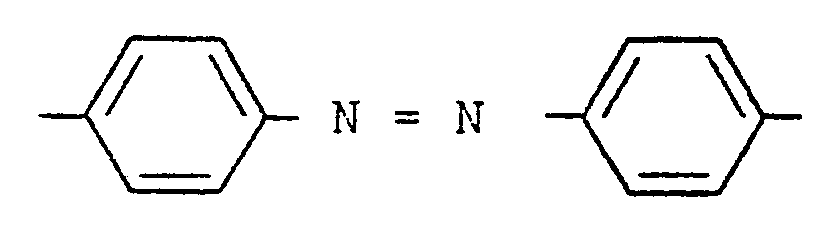
- Pleochroic dyes per se, are well known in the art. Reference to such materials may be readily found in the patent literature. See for example, U.S. Patents 3833287, 3960751, 4032219, 4105654, 4116861, 4128496, 4137193, 4145114, and 4154746. As will be discussed hereinafter, single dyes or mixtures of dyes may be employed. Pleochroic dyes containing azoic and stilbene linkages are well known in the patent literature and are representative of useful pleochroic dyes. Azo dyes wherein at least one portion of the molecule has the structural formula
- Stilbene derivative pleochroic dyes wherein at least one portion of the molecule has the structural formula
- R 1 , R 2 and R 3 are chromophoric Inducing organic groups, are.also useful In the present invention.
- a particularly preferred group of anthraquinone-based pleochroic dyes are represented by the structural formula
- R 1 and R 3 are independently selected organic sub stituents, preferably selected from the group consisting of
- R- can also be selected from the group consisting of H, OH, Cl and NO 2 , and wherein R 2 is H or NH 2 or OH; provided that alkyl contains 2 to about 20 carbon atoms and when either R 1 or R 3 is hydrogen, hydroxyl, Cl or NO 2 , the other is not hydrogen, hydroxyl, Cl or NO 2 .
- curve A is a representative curve showing relative transmission versus wavelength for a pair of crossed polarizers such as the iodine-containing H and K type film polarizers and other similar polarizers available commercially from Polaroid Corporation and others.
- This representative polarizer pair exhibits some transmission or leakage at all visible wavelengths with increased transmission between 400 and 500 nm. This results in observation of a dark blue color when the polarizers are crossed due to transmission of the blue light.
- Curve B of FIG 4 shows the transmission characteristics of a display device such as shown in FIG 1 using the same polarizing elements as in Curve A.
- the upward displacement of Curve B is due to the presence of the liquid crystal in the cell and the imperfect alignment and birefringent properties of the liquid crystal molecules. It can be seen that in the off or dark state a certain residual amount of light is transmitted through the display device. This light is readily detected by the eye and causes the display to appear brighter than desirable In the dark or dead state. Moreover, since the light leakage Is more pronounced at the blue wavelengths, the display appears to have a blue cast when a black or neutral density background may be more desirable.
- a typical photopic response curve is shown as Curve C in FIG 4. While this curve suggests relative insensitivity of the eye to light in the region between 400 and 500 nm, the blue leakage is readily observed due to the human eye's sensitivity to color hue.
- pleochroic dyes may be added which have the ability to absorb light in the visible region.
- FIG 5 shows the transmission curve of a magenta pleochroic dye, Curve D, and a yellow pleochroic dye, Curve E.
- the magenta dye, D absorbs broadly across the visible spectrum from 400 to 700 nm. Light which would otherwise be transmitted through the display device Is absorbed, reducing the background brightness in the "off" state and improving the overall contrast ratio.
- Dye E on the other hand, has a relatively narrow absorption band primarily in the blue region and is particularly useful to reduce the light In the wavelength of greatest leakage for the particular polarizing element illustrated. A mixture of both dyes would be particularly effective with these polarizing elements reducing light leakage broadly across the visible spectrum and also causing the resultant light transmission curve of the display to be more nearly neutral or flat across the visible spectrum.
- the pleochroic dye can also be used to alter the inherent color produced by the polarizer pair of a display.
- FIG 6 shows a transmission Curve F for a pair of crossed polarizers which is very transmissive in the blue region with good absorption in the red.
- a dye having a transmission curve such as G when used in a device such as shown in FIG 1, will provide a purple color in the off state and a white image in the on state.
- the dye-polarizer combination shown in FIG 6 is used in a device similar to that shown in FIG 1, but with the exterior polarizer 17 oriented so that its direction of polarization is substantially perpendicular to that of 21, a color on color effect Is achieved whereby in the off state, the color of the dye (red) is observed and in the on state, an image having the color of the crossed polarizer, e.g., blue, is displayed on a red background.
- displays utilizing blue transmissive crossed polarizer elements in both the paralle and crossed configurations with various pleochroic dyes can provide interesting color effects.
- the Image (on state) When the polarizers are parallel the Image (on state) will be white against a background which is a summation of the dye and polarizer color. Thus, for a magenta dye the background will be maroon, for a red dye, the background will be purple and for a yellow dye green. When the polarizer elements are crossed, the display will provide an image which is the color of the polarizer against a background the color of the dye in the on state.
- isotropic dyes can be added to the display to provide further color effects.
- An isotropic dye is a dye which does not align with the liquid crystal molecules.
- Useful isotropic dyes are those which are nonionic and stable in the presence of the nematic liquid crystal composition, which do not possess intrinsic dichroism and which absorb light in the visible spectrum. These may Include a large number of know dyes Including triarylmethane, amido anthraquinones, triaryl cyclopropane, tetra arylcyclobutane, and the like. The effect of such dyes will be additive to the effects explained above.
- the present invention can be further Illustrated by reference to the following examples.
- a twist nematic cell was prepared using glass cell walls having an orienting layer of silicon monoxide deposited on the interior of the walls by vapor deposition.
- the orienting layer was linear and the direction of orientation of the two surfaces were at an angle of about 85° to one another in the cell assembly.
- the liquid crystal was a positive nematic mixture of phenyl-cyclohexane liquid crystal compounds comprising by weight approximately: 14%.
- trans-4-n pentyl-(4'-cyanobiphenylyl) cyclohexane 26% trans-4-n propyl-4'cyanophenyl) cyclohexane; 36% trans 4-n-pentyl-(4 , cyanophenyl) cyclohexane; and 24% trans-4-nheptyl-(4'cyanophenyl) cyclohexane.
- This composition is available commercially under the trade designation Nematic Phase 1132 TNC "Licristal" from EM Laboratories, Inc.
- the polarizers used for the display was a pair of dichroic iodine film polarizers, Polaroid HN 42, having a 45% transmission ratio.
- R 2 is hydrogen and R 1 and R 3 are as shown in the Table I below.
- the contrast ratio of the displays was measured as a measure of the light transmitted in the on state compared to the light transmitted in the off state. This measurement was performed on an optical bench using a white light source and associated optics. Detection was by a photocell focused to receive light from the electrode area on the face of the cell, the photocell fitted with a photopic filter. An oscillescope was used to record the readings directly from the photocell. As can be seen in Table I the contrast ratios were significantly enhanced, Examples 7-9
- Displays were prepared as in Examples 2-6 except that a mixture of magenta and yellow dyes was used to provide a display having a more neutral density as well as improved contrast ratio.
- the dyes had the general structural formula of the dyes used in Examples 2-6 with R 1 and R 3 as shown in
Abstract
Improved twist nematic liquid crystal display (1) incorporating dynamic, internal, pleochroic polarizer. Preferred dynamic, internal, pleochroic polarizer comprises pleochroic dye admixed with liquid crystal composition (15). Display device (1) of present invention provides improved performance, as measured by contrast ratio, and can provide advantageous color effects.
Description
Description
Display Device With Dynamic Internal Polarizer
Technical Field
This invention relates to liquid crystal display devices. More particularly, this invention relates to twist nematic liquid crystal display devices incorporating a dynamic, internal, pleochroic polarizer.
Background Art
Twist nematic liquid crystal displays are well known and have found increased usage in a variety of electronic devices in recent years. Such display devices employ a twist nematic cell having on the inner surfaces, electrodes, a liquid crystal alignment layer, and, contained within the cell, a layer of liquid crystal. The alignment layer is oriented so as to cause the liquid crystal molecules to assume a twisted configuration e.g. a helical alignment across the cell. Under the influence of an electric field, the molecules of liquid crystal adjacent the electrodes are caused to realign in a characteristic way. Such a cell can act to rotate polarized light or allow the light to pass through without rotation depending on the alignment of the molecules. When combined with polarizer elements on either side of the liquid crystal layer, the combination can be made to act as a light valve, blocking all light (in the ideal case) from passing through in selected areas. In this way, the combination can be used as an information display device.
Since liquid crystal displays employ polarizing elements and aligned liquid crystal layers, their perfor-
mance is dependent on the optical properties of such materials. Generally, dichroic polarizers are employed in such displays. Due to the light absorption characteristics of the dichroic dye molecules in the polarizing element and imperfections in the molecular arrangements of these materials, polarizing elements do not generally act as ideal polarizing elements, but allow "leakage" of some light throughout all or a portion of the visible spectrum other than the desired polarized component. This leakage can be readily observed by crossing a pair of linear polarizing elements at the extinction angle and observing that light is transmitted through the crossed polarizers even though no light would be transmitted through a pair of ideal polarizers so crossed. The effect of this behavior on a twist nematic display is that some light "leaks" through the display even when the display is in the off state. This effect has prevented the construction of a satisfactory "dead panel" display, that is, a display which appears to be completely dark in the off state while still being sufficiently transmissive in the on state. This is a particularly troublesome problem in the construction of a display wherein the display is lighted with a light source placed behind the display since the light leakage affects the apparent photopic contrast ratio (the ratio of visible light transmitted in the on state versus the off state).
This condition is made worse by the imperfection of alignment and natural birefringent character of the liquid crystal material employed in the twist nematic cell. Because of the effect of the liquid crystal material on the light passing through the cell, the light leakage of the display device may be substantially greater than the leakage of the polarizing elements alone.
The resultant effect of the above characteristics is that significant amounts of light can pass through the display even in the off or dark state. A "dead panel" appearance is difficult to achieve with such a display and the contrast ratio between the on and off state is not normally as hir.h as desired for critical applications, such
as instrumentation displays and the like, where quick recognition of a change In state, i.e., "off" to "on", is essential. Moreover, the contrast ratio of the display when viewed at certain angles to the normal are signlficantly reduced due to birefringent effects of the liquid crystal molecules.
Disclosure Of Invention
The liquid crystal display devices of the present invention overcome many of the disadvantages of previously known displays by employing a dynamic, pleochroic, internal polarizer means in combination with a conventional twist nematic liquid crystal display means. In a preferred embodiment of the present invention, the internal polarizer means comprises one or more pleochroic dyes which. can absorb light in the visible region, i.e., nominally in the range of about 400 to 700 nanometers. Pleochroic dyes which are compatible with liquid crystals and which function in the known guest-host relationship can be controlled through application of an external stimulus, such as by application of an electric field to the liquid crystal layer. This effect is discussed, for example, In U.S. Patents 3597044, 3833287 and 4154746.
Thus, the polarizing effect of the pleochroic dye Is dynamic since it can be turned on and off. In the polarizing mode, the dye acts as a selective polarizer, absorbing certain wavelengths of polarized light vibrating parallel to its chromophoric axis. However, when caused to reorient by the application of an electric field across the liquid crystal layer, the dye allows light to pass substantially unaffected.
The result of using the dynamic internal polarizing means in combination with a pair of conventional, fixed, polarizing elements exterior to the liquid crystal layer is to absorb significant amounts of light which would otherwise contribute to leakage by the polarizing elements, i.e., light leaked through a pair of polarizers in the crossed or extinction position. The effect of this absorption can be
observed as a darker background in the off state and resulting enhanced contrast ratio and enhanced off-axis contrast. By proper choice of the pleochroic dye, polarizing elements, orientation of the polarizing elements, or addition of Isotropic dye, a more neutral density background or other desirable color effects can be achieved.
Since the preferred pleochroic dyes are absorbent in the orientation accompanying the off state of the device and substantially non-absorbent in the orientation corresponding to the on state of the liquid crystal display, the transmission or brightness of the display in the on state is not significantly reduced. As can be appreciated, the brightness and contrast ratio will be somewhat dependent on the optical order parameter of the dye. Thus, dyes having relatively high order parameters, e.g., 0.5 and most preferably 0.7, are particularly preferred for use In the present invention although dyes having lower order parameters can also be used where brightness is not of major concern. A typical twist nematic display which exhibits a photopic contrast ratio of about 135:1 can be improved by use of the dynamic, internal polarizing means according to the present invention to provide a photopic contrast ratio of about 200:1 or greater. Such improvement in contrast ratio can often be achieved while retaining about 80% of the transmission the display would exhibit without the internal polarizer. Moreover, the off-axis contrast of the display is improved due to reduction of the observable birefringent characteristics of the display. The pleochroic dye is used in combination with a liquid crystal composition having positive dielectric anisotropy. As used herein, the term "liquid crystal compositions having positive dielectric anisotropy" includes positive nematic liquid crystal compounds, mixtures of such compounds and mixtures of positive and negative compounds exhibiting net positive dielectric anisotropy. Other ingredients commonly used in liquid crystal mixtures can also be incorporated in the composition, for example,
chiral dopants, such as cholesteryl nonanoate, can be added as well as isotropic dyes and the like.
The pleochroic dye can be employed in varying amounts depending on the polarizer used, the light absorbing properties of the dye, the optical order parameter, the transmissivity required, etc. It.has been found that even small amounts of the dye, e.g., below 0.15., by weight of the liquid crystal composition, can be effective. Amounts above about 0.1% by weight and particularly above 0. 5% by weight, are preferred. As the amount of the dye is increased, the transmission of the display in the off state may be reduced and generally amounts greater than about 2% by weight are not used unless significant decreases In transmission can be tolerated. As noted above, dyes with relatively high optical order parameters are desirable since they can be employed In amounts which absorb significant amounts of light yet do not cause a decrease in the transmission beyond a desired level, e.g., about 80$ of the transmission level without the dye.
Brief Description of Drawings
FIGURE 1 is an exploded perspective view of the elements of a twist nematic display representing the molecules of liquid crystal in a helical twist configuration. FIGURE 2 is a cross section along line 2-2 of FIG 1 of the assembled device shown In FIG 1.
FIGURE 3 is an operative embodiment of the elements shown in FIG 1.
FIGURE 4 is a graph showing the transmission characteristics of typical polarizing elements and display devices and a superimposed photopic response curve.
FIGURE 5 is a graph showing transmission curves for certain pleochroic dyes imposed on certain of the curves shown in the graph of FIG 4.
FIGURE 6 is a graph showing transmission curves for a blue polarizer and a red pleochroic dye, which combination can provide a unique colored display.
Detailed Description
Referring now to the drawings, there is shown in FIGs 1 and 2 an exploded perspective view of the elements of a twist nematic liquid crystal display 1 comprising transparent cell walls 3 and 5. These cell walls 3 and 5 may be joined together at their perimeter by sealing means 7 to form a closed cell. Typically, the cell walls are of transparent glass or plastic, while the sealing means 7 can be an organic or inorganic sealant. Organic sealants are typified by heat and photo curing epoxide polymers, while inorganic sealants may be glass or metals.
The interior of the cell walls 3 and 5 generally carry one or more transparent, conductive electrodes 9 and 11. These are represented by a vertical stripe in FIG 1 for the sake of simplicity, although many complex single or multiple electrode patterns can be used to convey Information. Typically, a dot matrix electrode pattern or a seven- segment or other segmented electrode is used to convey the desired Information. Typically, these electrodes are vapordeposited coatings of metal oxides, such as indium oxide or tin oxide.
The inside surfaces of cell walls 3 and 5 also typically are provided with an orienting layer 13 having an orientation direction represented by arrows 14 running vertically on cell wall 3 and horizontally on cell wall 5. This orienting layer may be formed by rubbing the surface of the cell wall uniformly with rubbing compound, such as rouge, or other material, to orient the surface molecules of the cell wall in the desired pattern. Alternatively, a coating of silicon monoxide or other known alignment material can be vapor deposited in the desired pattern to act as an alignment layer. For most applications, a linear orienting pattern is applied uniformly across the cell wall although for some applications, differentially oriented pattern may be used where different areas, e.g., background versus electrode areas, are aligned in different directions.
The cell formed by cell walls 3 and 5 and sealing means 7 contains a nematic liquid crystal composition 15
(represented by oriented individual molecules in FIG 1) comprising one or more nematic liquid crystal compounds. The nematic liquid crystals typically comprise rod-like molecules which can be caused to assume a homogeneous (parallel) alignment. By orienting the alignment layers 13 on cells 3 and 5 such that they are substantially perpendicular to one another, the molecules of the nematic composition 15 are caused to assume a helical, twisted orientation rotated through about 90° from one cell wall to the other. Display cells containing liquid crystals having the twisted configuration are commonly called twisted nematic liquid crystal displays or twisted nematic field effect displays .
The nematic liquid crystals useful in the present invention are any of the liquid crystal materials which are useful in a twist nematic cell. Generally, nematic liquid crystals having positive dielectric anisotropy, or mixtures having a net positive dielectric anisotropy, are preferred. Many such materials and mixtures are well known. Typical liquid crystal compounds exhibiting positive anisotropy and useful with the pleochroic dyes described. herein are trans-4-n-pentyl-(4'-cyano-phenyD-cyclohexane, trans-4-n-pentyl-(4'-cyano-biphenyl-4)-cyclohexane, p-nhexylbenzylidene-p'-amino-benzonitrile, p-methoxybenzylidene-p'-amino-benzoinitrile, p-ethoxybenzylldene-p' aminobenzonitrlie, p-cyano-benzylidene-p'-n-butyoxyanillne, p-cyanobenzyl-idene-p'-octyloxyaniline, and compounds having the formula

wherein R = alkyl or alkoxy of 107 carbon atoms and X is alkyl or alkoxy of 1-10 carbon atoms.
Eutectic mixtures and combinations of all the above are also useful. Illustrative eutectic mixtures of 4'- substituted 4-cyanobiphenyls wherein the 4' substituents are alkyl or alkoxy of 3 to 8 carbon atoms. Representative is the commercially available "E-7" mixture from B.D.H. Ltd.
Yet another useful mixture of compounds comprises mixtures of the phenylcyclohexanes referred to above such as mixtures comprising the 4-alkyl-(4'-cyanophenyl)cyclohexanes, mixtures comprising 4-alkyl-(4'-cyanobiphenylyDcyclohexanes, and mixtures comprising both types of compounds. One useful commercial mixture is a four-component mixture available from EM Laboratories, Inc., identified as Nematic Phase 1132 TNC "Licristal". This mixture comprises by weight approximately: 145- trans-4-n-pentyl-(4'-cyanobiphenylyl)cyclo- hexane, 26% trans-4-n-propyl-(4'cyanophenyl)cyclohexane, 36% trans-4-n-pentyl-(4'-cyanoρhenyl)cyclohexane, and 24% trans-4-n-heptyl-(4'cyanophenyl)cyclohexane.
Useful groups of nematic liquid crystal compounds and compositions having negative anisotropy are represented by the following groups of compounds: p-methoxybenzylidenep'-n-butylanillne, p-methoxybenzylldene-p'-amino-phenylbenzoate, p-methoxybenzylidene-p'-amino-phenylacetate, p-azoxyanlsole, p-n-butylberizoic acid p'-n-hexyloxyphenyl ester, p(p'-ethoxyphenylazo)phenyl heptanoate, p(p'-ethoxyphenylazo)phenyl undecylenate, p-butyoxy benzylidene-p'- pentylaniline, and p-ethoxybenzylidene-p'-n-butylanillne.
Certain of the negative nematic liquid crystalline compounds described above are disclosed in U.S. Patents Re 29349, 3829491, 3809656, 3994567 and 3703331. When the negative nematic compounds are combined with the positive nematic compounds, combinations can be provided which have a net positive anisotropy. This may be achieved using only relatively low percentages of materials with high positive anisotropy when the other materials have relatively low negative anisotropy.
The liquid crystal In the twisted configuration has the ability to cause polarized light to rotate 90° (or other angle between the direction of orientation of the cel walls, e.g. typically between 75° and 105°) as it passes through the cell.
When coupled with a pair of polarizing elements 17 and 19 (polarizing light in the direction represented by arrows 21) on either side of the liquid crystal material 15
(located either interior or exterior (shown) of cell walls 3 and 5) the combination can function as a light valve by application of an electric field from voltage source 23 through switch 25. In operation, light, e.g., from a source represented by bulb is used to back-light the display. The light source may be separated from the display by a diffusing layer, louvered film or the like to cause the light to more uniformly Illuminate the display. Light from source 27 passes through and is polarized vertically by element 19. The vertically polarized light is rotated by liquid crystal 15 so that it exits the liquid crystal layer polarized horizontally. As a result, the majority of light is blocked by polarizing element 17, because it has a polarization direction perpendicular to the light emerging from liquid crystal 15, and little light (except that leaked by the polarizer) is observed by viewer 29.
However, when switch 25 is closed, as shown In FIG 3, the molecules of liquid crystal 15 which are between electrodes 9 and 11 are caused to realign and no longer rotate the polarized light entering the cell. The light passing through this area of the cell can, therefore, pass through polarizer 17 and is observed as a bright area by observer 29. Thus, in the "off" state, the observed side of the display Is ideally dark or "dead", even though the light source is continuously lit. The contrast ratio of the display is the ratio of visible light transmitted in the on state to the visible light transmitted in the off state. It Is desired that the contrast ratio be a maximum for a given light source and that the panel appear as dark as possible in the off state.
Having explained the operation of the typical twist nematic display, it can be seen that the performance as measured by the contrast ratio and darkness in the off state is partially dependent on the leakage characteristics of the polarizing elements. Further, the color of the background or image portion of the cell is dependent on the particular
spectral bands of light passed by the polarizer as discussed hereafter. The performance is also dependent on the ability of the liquid crystal to rotate the incoming polarized light precisely so that it is presented to the second polarizer at the desired angle, e.g., angle of maximum extinction.
Displays having improved performance can be constructed according to the present invention by employing a dynamic internal pleochroic polarizer means. More particularly, means which can be controlled to absorb certain wavelengths of light or pass light, as desired, is employed in the improved displays of this invention. By the addition of a guest pleochroic dye to the liquid crystal composition, the liquid crystal layer 15 can be made to act as a dynamic, internal, pleochroic polarizing means to provide enhanced display contrast or other advantageous color effects.
The pleochroic dye molecules and liquid crystal molecules sympathetically align in what is known as a 'guest-host relationship (see, for example, U.S. Patents 3833287 and 4154746). A change in orientation in the liquid crystal also causes a corresponding change of orientation in the dye. Because the dye is pleochroic, i.e., absorbs light which vibrates parallel to its chromophoric axis and does not absorb light vibrating perpendicular to its chromophoric axis, when used in a display device such as shown In FIG 1, the dye will absorb light in the off state and allow light to pass In the electrode areas in the on state.
Pleochroic dyes, per se, are well known in the art. Reference to such materials may be readily found in the patent literature. See for example, U.S. Patents 3833287, 3960751, 4032219, 4105654, 4116861, 4128496, 4137193, 4145114, and 4154746. As will be discussed hereinafter, single dyes or mixtures of dyes may be employed. Pleochroic dyes containing azoic and stilbene linkages are well known in the patent literature and are representative of useful pleochroic dyes. Azo dyes wherein at least one portion of the molecule has the structural formula

Anthraqulnone-based dyes having the general formula

A particularly preferred group of anthraquinone-based pleochroic dyes are represented by the structural formula


These dyes are particularly preferred dye to their relatively high optical order parameters and strong absorption at various desirable wavelengths. The effect of the pleochroic dye can be more clearly understood by further reference to FIGs 4, 5 and 6 wherein curve A is a representative curve showing relative transmission versus wavelength for a pair of crossed polarizers such as the iodine-containing H and K type film polarizers and other similar polarizers available commercially from Polaroid Corporation and others. This representative polarizer pair exhibits some transmission or leakage at all visible wavelengths with increased transmission between 400 and 500 nm. This results in observation of a dark blue color when the polarizers are crossed due to transmission of the blue light.
Curve B of FIG 4 shows the transmission characteristics of a display device such as shown in FIG 1 using the same polarizing elements as in Curve A. The upward displacement of Curve B is due to the presence of the liquid crystal in the cell and the imperfect alignment and birefringent properties of the liquid crystal molecules. It can be seen that in the off or dark state a certain residual amount of light is transmitted through the display device. This light is readily detected by the eye and causes the display to appear brighter than desirable In the dark or dead state. Moreover, since the light leakage Is more pronounced at the blue wavelengths, the display appears to have a blue cast when a black or neutral density background may be more desirable. A typical photopic response curve is shown as Curve C in FIG 4. While this curve suggests relative insensitivity of the eye to light in the region between 400 and 500 nm, the blue leakage is readily observed due to the
human eye's sensitivity to color hue.
In order to reduce the light leakage and increase both the on/off contrast ratio and the darkness in the off state, pleochroic dyes may be added which have the ability to absorb light in the visible region. FIG 5 shows the transmission curve of a magenta pleochroic dye, Curve D, and a yellow pleochroic dye, Curve E. The magenta dye, D, absorbs broadly across the visible spectrum from 400 to 700 nm. Light which would otherwise be transmitted through the display device Is absorbed, reducing the background brightness in the "off" state and improving the overall contrast ratio. Dye E, on the other hand, has a relatively narrow absorption band primarily in the blue region and is particularly useful to reduce the light In the wavelength of greatest leakage for the particular polarizing element illustrated. A mixture of both dyes would be particularly effective with these polarizing elements reducing light leakage broadly across the visible spectrum and also causing the resultant light transmission curve of the display to be more nearly neutral or flat across the visible spectrum.
The pleochroic dye can also be used to alter the inherent color produced by the polarizer pair of a display. FIG 6 shows a transmission Curve F for a pair of crossed polarizers which is very transmissive in the blue region with good absorption in the red. A dye having a transmission curve such as G, when used in a device such as shown in FIG 1, will provide a purple color in the off state and a white image in the on state. Alternatively, if the dye-polarizer combination shown in FIG 6 is used in a device similar to that shown in FIG 1, but with the exterior polarizer 17 oriented so that its direction of polarization is substantially perpendicular to that of 21, a color on color effect Is achieved whereby in the off state, the color of the dye (red) is observed and in the on state, an image having the color of the crossed polarizer, e.g., blue, is displayed on a red background.
With reference to FIG 1, displays utilizing blue transmissive crossed polarizer elements in both the paralle and crossed configurations with various pleochroic dyes can provide interesting color effects. When the polarizers are parallel the Image (on state) will be white against a background which is a summation of the dye and polarizer color. Thus, for a magenta dye the background will be maroon, for a red dye, the background will be purple and for a yellow dye green. When the polarizer elements are crossed, the display will provide an image which is the color of the polarizer against a background the color of the dye in the on state.
In still another embodiment of the invention, isotropic dyes can be added to the display to provide further color effects. An isotropic dye is a dye which does not align with the liquid crystal molecules. Useful isotropic dyes are those which are nonionic and stable in the presence of the nematic liquid crystal composition, which do not possess intrinsic dichroism and which absorb light in the visible spectrum. These may Include a large number of know dyes Including triarylmethane, amido anthraquinones, triaryl cyclopropane, tetra arylcyclobutane, and the like. The effect of such dyes will be additive to the effects explained above. The present invention can be further Illustrated by reference to the following examples.
Examples 1 - 6
A twist nematic cell was prepared using glass cell walls having an orienting layer of silicon monoxide deposited on the interior of the walls by vapor deposition. The orienting layer was linear and the direction of orientation of the two surfaces were at an angle of about 85° to one another in the cell assembly. The liquid crystal was a positive nematic mixture of phenyl-cyclohexane liquid crystal compounds comprising by weight approximately: 14%. trans-4-n pentyl-(4'-cyanobiphenylyl) cyclohexane;
26% trans-4-n propyl-4'cyanophenyl) cyclohexane; 36% trans 4-n-pentyl-(4,cyanophenyl) cyclohexane; and 24% trans-4-nheptyl-(4'cyanophenyl) cyclohexane. This composition is available commercially under the trade designation Nematic Phase 1132 TNC "Licristal" from EM Laboratories, Inc.
The polarizers used for the display was a pair of dichroic iodine film polarizers, Polaroid HN 42, having a 45% transmission ratio.
Additional displays containing various magenta anthraquinone-based pleochroic dyes were prepared, the dyes having the following structure


Displays were prepared as in Examples 2-6 except that a mixture of magenta and yellow dyes was used to provide a display having a more neutral density as well as improved contrast ratio. The dyes had the general structural formula of the dyes used in Examples 2-6 with R1 and R3 as shown in
Table II.

Claims
1. A liquid crystal display device (1) having an improved contrast ratio comprising a twist nematic cell comprising parallel spaced wall plates (3, 5) forming a cell, electrodes (9, 11) arranged to provide an electric field across said cell, a composition comprising a nematic liquid crystal composition (15) within said cell, the interior of said wall plates (3, 5) being surface oriented to cause said liquid crystal composition (15) to assume a twisted molecular structure along an axis normal to the parallel surfaces of said wall plates (39 5) said display device (1) including polarizing elements (17, 19) on either side of said liquid crystal composition (15) wherein the improvement comprises a dynamic, pleochroic, internal polarizing means interposed between said polarizing elements (17, 19).
2. A display device (1) according to claim 1 wherein said nematic liquid crystal composition has a positive dielectric anisotropy.
3. A display device (1) according to claim 2 wherein said polarizing elements (17, 19) are located interior of the wall plates (3, 5) of said twist nematic cell.
4. A display device (1) according to claim 2 wherein said polarizing elements (17, 19) are located exterior of the wall plates (3, 5) of said twist nematic cell.
5. A display device (1) according to claim 2 wherein said polarizing elements (17, 19) are linear polarizers oriented so that their relative direction of polarization is substantially parallel and wherein the direction of polarization of at least one polarizing element is substantially perpendicular to the direction of surface orientation of one of said wall plates (3, 5).
6. A display device (1) according to claim 2 wherein said dynamic polarizing means can be controlled by application of an electric field across said cell.
7. A display device (1) according to claim 2 wherein said dynamic, pleochroic, internal polarizing means comprises at least one pleochroic dye admixed with said liqui crystal composition (15) in an amount effective .to provide an improved contrast ratio.
8. A display device (1) according to claim 7 wherein said pleochroic dye absorbs light at all wavelengths between about 450 to 600 nanometers.
9. A display device (1) according to claims wherein said device also has a substantially neutral density color inthe off state, wherein said pleochroic dye absorbs light at the wavelengths of substantial leakage, of said pair of polarizing elements (17, 19).
10. A display device (1) according to claim 7 wherein said dynamic, pleochroic, internal polarizing means comprises a mixture of pleochroic dyes having different light absorption characteristics.
11. A display device (1) according to claim 7 wherein said device (1) includes at least one Isotropic dye admixed with said liquid crystal composition (15).
12. A display device (1) according to claim 7 wherein said pleochroic dye has the following structural formula:


and mixtures thereof and wherein R3 and also be selected from the group consisting of H, OH, Cl and NO2, and wherein R2 is H, OH or NH2; provided that alkyl contains 2 to about 20 carbon atoms and that when either R1 or R3 is H, OH, Cl or NO2 the other Is not H, OH, Cl or NO2.
Applications Claiming Priority (2)
| Application Number | Priority Date | Filing Date | Title |
|---|---|---|---|
| US6128679A | 1979-07-27 | 1979-07-27 | |
| US61286 | 1993-05-14 |
Publications (1)
| Publication Number | Publication Date |
|---|---|
| WO1981000463A1 true WO1981000463A1 (en) | 1981-02-19 |
Family
ID=22034806
Family Applications (1)
| Application Number | Title | Priority Date | Filing Date |
|---|---|---|---|
| PCT/US1980/000913 WO1981000463A1 (en) | 1979-07-27 | 1980-07-22 | Display device with dynamic internal polarizer |
Country Status (3)
| Country | Link |
|---|---|
| EP (1) | EP0033334A4 (en) |
| JP (1) | JPS56500944A (en) |
| WO (1) | WO1981000463A1 (en) |
Cited By (9)
| Publication number | Priority date | Publication date | Assignee | Title |
|---|---|---|---|---|
| FR2523147A1 (en) * | 1982-03-13 | 1983-09-16 | Nippon Kanko Shikiso Kenkyusho | DICHROIC DYES FOR LIQUID CRYSTALS AND LIQUID CRYSTAL COMPOSITIONS |
| FR2535733A1 (en) * | 1982-10-28 | 1984-05-11 | Ivaschenko Alexandr V | Acylated anthraquinone cpds. |
| EP0130492A2 (en) * | 1983-07-01 | 1985-01-09 | Koninklijke Philips Electronics N.V. | Liquid crystal display |
| FR2578064A1 (en) * | 1985-02-22 | 1986-08-29 | Casio Computer Co Ltd | LIQUID CRYSTAL LIGHT SHUTTER |
| EP0394416A1 (en) * | 1988-10-19 | 1990-10-31 | FERGASON, James L. | Variable density light control apparatus and method |
| US5479277A (en) * | 1988-10-19 | 1995-12-26 | Fergason; James L. | Method of making a variable density light control apparatus by stretching an unsupported film |
| US5523863A (en) * | 1988-10-19 | 1996-06-04 | Fergason; James L. | Controlled liquid crystal optical polarizer method and apparatus |
| WO2000068569A1 (en) | 1999-05-05 | 2000-11-16 | Ramona Themel | Wind power facility with a vertical rotor |
| CN112466931A (en) * | 2020-11-27 | 2021-03-09 | Tcl华星光电技术有限公司 | Electrode structure, preparation method thereof and thin film transistor |
Citations (7)
| Publication number | Priority date | Publication date | Assignee | Title |
|---|---|---|---|---|
| US3731986A (en) * | 1971-04-22 | 1973-05-08 | Int Liquid Xtal Co | Display devices utilizing liquid crystal light modulation |
| US4032219A (en) * | 1974-10-21 | 1977-06-28 | The Secretary Of State For Defence In Her Britannic Majesty's Government Of The United Kingdom Of Great Britian And Northern Ireland | Liquid crystal display devices |
| US4054368A (en) * | 1974-12-16 | 1977-10-18 | Siemens Aktiengesellschaft | Compound indicator device containing at least one liquid crystal cell |
| US4097130A (en) * | 1977-03-11 | 1978-06-27 | General Electric Company | Multi-colored liquid crystal displays |
| US4105299A (en) * | 1977-04-11 | 1978-08-08 | Minnesota Mining And Manufacturing Company | Electro-optical devices containing methine arylidene dyes |
| EP0002104A1 (en) * | 1977-10-14 | 1979-05-30 | BDH Chemicals Limited | Pleochroic dyes suitable for use in solution with liquid crystal materials for electro-optic device applications |
| DE2920730A1 (en) * | 1978-05-23 | 1979-11-29 | Minnesota Mining & Mfg | LIQUID CRYSTAL SYSTEMS AND ELECTRO-OPTICAL DISPLAYS |
-
1980
- 1980-07-22 WO PCT/US1980/000913 patent/WO1981000463A1/en not_active Application Discontinuation
- 1980-07-22 JP JP50191080A patent/JPS56500944A/ja active Pending
-
1981
- 1981-02-24 EP EP19800901602 patent/EP0033334A4/en not_active Ceased
Patent Citations (7)
| Publication number | Priority date | Publication date | Assignee | Title |
|---|---|---|---|---|
| US3731986A (en) * | 1971-04-22 | 1973-05-08 | Int Liquid Xtal Co | Display devices utilizing liquid crystal light modulation |
| US4032219A (en) * | 1974-10-21 | 1977-06-28 | The Secretary Of State For Defence In Her Britannic Majesty's Government Of The United Kingdom Of Great Britian And Northern Ireland | Liquid crystal display devices |
| US4054368A (en) * | 1974-12-16 | 1977-10-18 | Siemens Aktiengesellschaft | Compound indicator device containing at least one liquid crystal cell |
| US4097130A (en) * | 1977-03-11 | 1978-06-27 | General Electric Company | Multi-colored liquid crystal displays |
| US4105299A (en) * | 1977-04-11 | 1978-08-08 | Minnesota Mining And Manufacturing Company | Electro-optical devices containing methine arylidene dyes |
| EP0002104A1 (en) * | 1977-10-14 | 1979-05-30 | BDH Chemicals Limited | Pleochroic dyes suitable for use in solution with liquid crystal materials for electro-optic device applications |
| DE2920730A1 (en) * | 1978-05-23 | 1979-11-29 | Minnesota Mining & Mfg | LIQUID CRYSTAL SYSTEMS AND ELECTRO-OPTICAL DISPLAYS |
Cited By (12)
| Publication number | Priority date | Publication date | Assignee | Title |
|---|---|---|---|---|
| FR2523147A1 (en) * | 1982-03-13 | 1983-09-16 | Nippon Kanko Shikiso Kenkyusho | DICHROIC DYES FOR LIQUID CRYSTALS AND LIQUID CRYSTAL COMPOSITIONS |
| FR2535733A1 (en) * | 1982-10-28 | 1984-05-11 | Ivaschenko Alexandr V | Acylated anthraquinone cpds. |
| EP0130492A2 (en) * | 1983-07-01 | 1985-01-09 | Koninklijke Philips Electronics N.V. | Liquid crystal display |
| EP0130492A3 (en) * | 1983-07-01 | 1987-07-15 | Koninklijke Philips Electronics N.V. | Liquid crystal display |
| FR2578064A1 (en) * | 1985-02-22 | 1986-08-29 | Casio Computer Co Ltd | LIQUID CRYSTAL LIGHT SHUTTER |
| EP0394416A1 (en) * | 1988-10-19 | 1990-10-31 | FERGASON, James L. | Variable density light control apparatus and method |
| EP0394416A4 (en) * | 1988-10-19 | 1992-07-08 | James L. Fergason | Variable density light control apparatus and method |
| US5479277A (en) * | 1988-10-19 | 1995-12-26 | Fergason; James L. | Method of making a variable density light control apparatus by stretching an unsupported film |
| US5523863A (en) * | 1988-10-19 | 1996-06-04 | Fergason; James L. | Controlled liquid crystal optical polarizer method and apparatus |
| WO2000068569A1 (en) | 1999-05-05 | 2000-11-16 | Ramona Themel | Wind power facility with a vertical rotor |
| CN112466931A (en) * | 2020-11-27 | 2021-03-09 | Tcl华星光电技术有限公司 | Electrode structure, preparation method thereof and thin film transistor |
| US11757044B2 (en) | 2020-11-27 | 2023-09-12 | Tcl China Star Optoelectronics Technology Co., Ltd. | Electrode structure, manufacturing method thereof, and thin film transistor |
Also Published As
| Publication number | Publication date |
|---|---|
| JPS56500944A (en) | 1981-07-09 |
| EP0033334A1 (en) | 1981-08-12 |
| EP0033334A4 (en) | 1983-01-14 |
Similar Documents
| Publication | Publication Date | Title |
|---|---|---|
| US4032219A (en) | Liquid crystal display devices | |
| US3960750A (en) | Electro-optical display | |
| US4759612A (en) | Twisted nematic type liquid crystal display device having a color polarizer to provide an achromatic or colorless background | |
| US4211473A (en) | Liquid crystal display devices | |
| US4097128A (en) | Liquid crystal color display devices | |
| US4697884A (en) | Liquid crystal display having degree of twist and thickness for improved multiplexing | |
| GB2037803A (en) | Liquid crystal mixture | |
| US4609255A (en) | Liquid crystal display with twist angle less than 80 degrees | |
| JPS6115915B2 (en) | ||
| JP2784205B2 (en) | Transmissive liquid crystal display | |
| Scheffer et al. | Investigation of the electro‐optical properties of 270° chiral nematic layers in the birefringence mode | |
| WO1981000463A1 (en) | Display device with dynamic internal polarizer | |
| JPH07199233A (en) | Liquid crystal element and display using the element | |
| JPH10292175A (en) | Guest-host liquid crystal display device, and guest host liquid crystal composition | |
| JPS64439B2 (en) | ||
| Bloom et al. | Criteria for evaluating pleochroic dye liquid-crystal displays | |
| JPS5866917A (en) | Field effect type liquid crystal cell | |
| Raj | Dichroic display technology potentials and limitations | |
| Scheffer et al. | Guest-host displays | |
| JPH0465369B2 (en) | ||
| JPH10111523A (en) | Guest-host liquid crystal display device | |
| GB2108698A (en) | Liquid crystal displays | |
| JPS62125331A (en) | Color liquid crystal display | |
| JPS6121508B2 (en) | ||
| JP2812601B2 (en) | Liquid crystal display |
Legal Events
| Date | Code | Title | Description |
|---|---|---|---|
| AK | Designated states |
Designated state(s): JP |
|
| AL | Designated countries for regional patents |
Designated state(s): AT CH DE FR GB LU NL SE |
|
| WWE | Wipo information: entry into national phase |
Ref document number: 1980901602 Country of ref document: EP |
|
| WWP | Wipo information: published in national office |
Ref document number: 1980901602 Country of ref document: EP |
|
| WWR | Wipo information: refused in national office |
Ref document number: 1980901602 Country of ref document: EP |
|
| WWW | Wipo information: withdrawn in national office |
Ref document number: 1980901602 Country of ref document: EP |