USRE47999E1 - Vehicle rearview mirror system, and vehicle provided with said vehicle rearview mirror system - Google Patents
Vehicle rearview mirror system, and vehicle provided with said vehicle rearview mirror system Download PDFInfo
- Publication number
- USRE47999E1 USRE47999E1 US16/039,100 US201316039100A USRE47999E US RE47999 E1 USRE47999 E1 US RE47999E1 US 201316039100 A US201316039100 A US 201316039100A US RE47999 E USRE47999 E US RE47999E
- Authority
- US
- United States
- Prior art keywords
- posture
- vehicle
- display device
- main body
- image
- Prior art date
- Legal status (The legal status is an assumption and is not a legal conclusion. Google has not performed a legal analysis and makes no representation as to the accuracy of the status listed.)
- Active, expires
Links
- 238000001514 detection method Methods 0.000 claims description 5
- 239000004973 liquid crystal related substance Substances 0.000 description 62
- 238000010276 construction Methods 0.000 description 21
- 238000006243 chemical reaction Methods 0.000 description 8
- 238000005286 illumination Methods 0.000 description 7
- 230000000717 retained effect Effects 0.000 description 4
- 230000004075 alteration Effects 0.000 description 2
- 238000010586 diagram Methods 0.000 description 2
- 239000000470 constituent Substances 0.000 description 1
- 230000008878 coupling Effects 0.000 description 1
- 238000010168 coupling process Methods 0.000 description 1
- 238000005859 coupling reaction Methods 0.000 description 1
- 208000002173 dizziness Diseases 0.000 description 1
- 230000000694 effects Effects 0.000 description 1
- 238000004519 manufacturing process Methods 0.000 description 1
- 238000000034 method Methods 0.000 description 1
- 230000000007 visual effect Effects 0.000 description 1
Images


Classifications
-
- B—PERFORMING OPERATIONS; TRANSPORTING
- B60—VEHICLES IN GENERAL
- B60R—VEHICLES, VEHICLE FITTINGS, OR VEHICLE PARTS, NOT OTHERWISE PROVIDED FOR
- B60R1/00—Optical viewing arrangements; Real-time viewing arrangements for drivers or passengers using optical image capturing systems, e.g. cameras or video systems specially adapted for use in or on vehicles
- B60R1/20—Real-time viewing arrangements for drivers or passengers using optical image capturing systems, e.g. cameras or video systems specially adapted for use in or on vehicles
- B60R1/22—Real-time viewing arrangements for drivers or passengers using optical image capturing systems, e.g. cameras or video systems specially adapted for use in or on vehicles for viewing an area outside the vehicle, e.g. the exterior of the vehicle
- B60R1/23—Real-time viewing arrangements for drivers or passengers using optical image capturing systems, e.g. cameras or video systems specially adapted for use in or on vehicles for viewing an area outside the vehicle, e.g. the exterior of the vehicle with a predetermined field of view
- B60R1/26—Real-time viewing arrangements for drivers or passengers using optical image capturing systems, e.g. cameras or video systems specially adapted for use in or on vehicles for viewing an area outside the vehicle, e.g. the exterior of the vehicle with a predetermined field of view to the rear of the vehicle
-
- B—PERFORMING OPERATIONS; TRANSPORTING
- B60—VEHICLES IN GENERAL
- B60R—VEHICLES, VEHICLE FITTINGS, OR VEHICLE PARTS, NOT OTHERWISE PROVIDED FOR
- B60R1/00—Optical viewing arrangements; Real-time viewing arrangements for drivers or passengers using optical image capturing systems, e.g. cameras or video systems specially adapted for use in or on vehicles
- B60R1/12—Mirror assemblies combined with other articles, e.g. clocks
-
- B—PERFORMING OPERATIONS; TRANSPORTING
- B60—VEHICLES IN GENERAL
- B60R—VEHICLES, VEHICLE FITTINGS, OR VEHICLE PARTS, NOT OTHERWISE PROVIDED FOR
- B60R1/00—Optical viewing arrangements; Real-time viewing arrangements for drivers or passengers using optical image capturing systems, e.g. cameras or video systems specially adapted for use in or on vehicles
- B60R1/02—Rear-view mirror arrangements
- B60R1/04—Rear-view mirror arrangements mounted inside vehicle
-
- B—PERFORMING OPERATIONS; TRANSPORTING
- B60—VEHICLES IN GENERAL
- B60R—VEHICLES, VEHICLE FITTINGS, OR VEHICLE PARTS, NOT OTHERWISE PROVIDED FOR
- B60R1/00—Optical viewing arrangements; Real-time viewing arrangements for drivers or passengers using optical image capturing systems, e.g. cameras or video systems specially adapted for use in or on vehicles
- B60R1/12—Mirror assemblies combined with other articles, e.g. clocks
- B60R2001/1253—Mirror assemblies combined with other articles, e.g. clocks with cameras, video cameras or video screens
-
- B—PERFORMING OPERATIONS; TRANSPORTING
- B60—VEHICLES IN GENERAL
- B60R—VEHICLES, VEHICLE FITTINGS, OR VEHICLE PARTS, NOT OTHERWISE PROVIDED FOR
- B60R2300/00—Details of viewing arrangements using cameras and displays, specially adapted for use in a vehicle
- B60R2300/70—Details of viewing arrangements using cameras and displays, specially adapted for use in a vehicle characterised by an event-triggered choice to display a specific image among a selection of captured images
-
- B—PERFORMING OPERATIONS; TRANSPORTING
- B60—VEHICLES IN GENERAL
- B60R—VEHICLES, VEHICLE FITTINGS, OR VEHICLE PARTS, NOT OTHERWISE PROVIDED FOR
- B60R2300/00—Details of viewing arrangements using cameras and displays, specially adapted for use in a vehicle
- B60R2300/80—Details of viewing arrangements using cameras and displays, specially adapted for use in a vehicle characterised by the intended use of the viewing arrangement
- B60R2300/802—Details of viewing arrangements using cameras and displays, specially adapted for use in a vehicle characterised by the intended use of the viewing arrangement for monitoring and displaying vehicle exterior blind spot views
- B60R2300/8026—Details of viewing arrangements using cameras and displays, specially adapted for use in a vehicle characterised by the intended use of the viewing arrangement for monitoring and displaying vehicle exterior blind spot views in addition to a rear-view mirror system
-
- H—ELECTRICITY
- H04—ELECTRIC COMMUNICATION TECHNIQUE
- H04N—PICTORIAL COMMUNICATION, e.g. TELEVISION
- H04N7/00—Television systems
- H04N7/18—Closed-circuit television [CCTV] systems, i.e. systems in which the video signal is not broadcast
Definitions
- the present invention relates to a vehicle rearview mirror system and a vehicle provided with the vehicle rearview mirror system.
- this vehicle rearview mirror system there is proposed a construction in which a vehicle mirror main body is inclined between a posture of the vehicle mirror main body when a driver watches a vehicle rear side appearing in a half mirror and a posture of the vehicle mirror main body when the driver watches an image which is displayed on a liquid crystal display screen of a liquid crystal display device.
- the present invention has been made in view of the circumstance mentioned above, and it is an object of the present invention to provide: a vehicle rearview mirror system having a construction in which a display device is switched on or off in conjunction with alteration of a vehicle mirror main body when there is employed a construction in which the vehicle mirror main body is inclined between a posture of the vehicle mirror main body when a driver watches a vehicle rear side appearing in a half mirror and a posture of the vehicle mirror main body when the driver watches an image which is displayed on a display screen of the display device; and a vehicle having the vehicle rearview mirror system.
- a vehicle rearview mirror system of the present invention is provided with: a display device in which is provided a signal processing unit to construct an image by an image signal outputted from an image receiving unit of a vehicle-mounted camera and then cause displays to a display screen the constructed image; a vehicle mirror main body in which is incorporated; an operating lever member; and a power supply switch.
- a posture thereof is altered between a posture when a driver watches a vehicle rear side appearing in a half mirror and a posture when the driver watches an image which is displayed on a display screen of a display device.
- the operating lever member is employed to alter the posture of the vehicle mirror main body, and the power supply switch switches on or off the display device in conjunction with operation of the operating lever member.
- a display device in conjunction with alteration the posture of a vehicle mirror main body when there is employed a construction in which incline of the vehicle mirror main body between a posture of the vehicle mirror main body when a driver watches a vehicle rear side reflected in a half mirror and a posture of the vehicle mirror main body when the driver watches an image displayed on a display screen of the display device
- FIG. 1 is a plan view when a vehicle provided with a vehicle rearview mirror system according to the present invention is seen from a top side.
- FIG. 2 is a schematic view showing a schematic construction of a vehicle mirror main body shown in FIG. 1 , and is also a view showing a posture of the vehicle mirror main body when a driver watches a vehicle rear side appearing in a half mirror.
- FIG. 3 is a schematic view showing a schematic construction of a vehicle mirror main body shown in FIG. 1 , and is also a view showing a posture of the vehicle mirror main body when a driver watches an image which is displayed on a liquid crystal display screen of a liquid crystal display device.
- FIG. 4 is a block diagram showing a circuit construction of a liquid crystal display device according to a first embodiment of the vehicle rearview mirror system according to the present invention.
- FIG. 5 is an illustrative view for illustrating a failure exerted by a difference between an aspect ratio of an image which is constructed by an image signal having been output from an image receiving unit shown in FIG. 4 and an aspect ratio of the liquid crystal display screen shown in FIGS. 2 and 3 , wherein FIG. 5 (a) is an illustrative view illustrating an aspect ratio of the image that is constructed by the image signal having been output from the image receiving unit, FIG. 5 (b) is an illustrative view of the aspect ratio of the liquid crystal display screen shown in FIGS. 2 and 3 , FIG.
- FIG. 5 (c) is an illustrative view illustrating a failure when the image signal having been output from the image receiving unit is employed as it is, and then, an image is displayed on the liquid crystal display screen
- FIG. 5 (d) is an illustrative view in a case of converting the aspect ratio of the image that is constructed by the image signal having been output from the image receiving unit and displaying an image of the converted aspect ratio on the liquid crystal display screen.
- FIG. 6 is an illustrative view conceptually showing conversion of the aspect ratio
- FIG. 6 (a) is an illustrative view in a case where an attempt is made to carry out conversion of an aspect ratio while clipping an upper image portion which is unrequired to be seen at the time of driving from the image that is constructed by the image signal having been output from the image receiving unit of the vehicle-mounted camera
- FIG. 6 (b) is an illustrative view in a case where an attempt is made to carry out conversion of an aspect ratio while clipping a lower image portion which is unrequired to be seen at the time of driving from the image that is constructed by the image signal having been output from the image receiving unit of the vehicle-mounted camera
- FIG. 6 (b) is an illustrative view in a case where an attempt is made to carry out conversion of an aspect ratio while clipping a lower image portion which is unrequired to be seen at the time of driving from the image that is constructed by the image signal having been output from the image receiving unit of the vehicle-mounted
- 6 (c) is an illustrative view in a case where an attempt is made to carry out conversion of an aspect ratio while clipping an upper unit and a lower image portions which are unrequired to be seen at the time of driving from the image that is constructed by the image signal having been output from the image receiving unit of the vehicle-mounted camera.
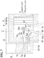
- FIG. 7 is an illustrative view of a second embodiment of the vehicle rearview mirror system according to the present invention, and is also a view showing a posture of a vehicle mirror main body when a driver watches a vehicle rear side appearing in a half mirror.
- FIG. 8 is a view showing a posture of the vehicle mirror main body when a driver watches the image that is displayed on a liquid crystal display screen of a liquid crystal display device while the vehicle mirror main body shown in FIG. 7 is inclined.
- FIG. 9 is a block diagram showing a circuit construction of the liquid crystal display device according to the second embodiment, of the vehicle rearview mirror system according to the present invention.
- FIG. 1 is a plan view when a vehicle provided with a vehicle rearview mirror system according to the present invention is seen from a top side.
- reference numeral 1 designates a vehicle
- reference numeral 2 designates a vehicle-mounted camera
- reference numeral 3 designates a vehicle mirror main body
- reference numeral 4 designates a driver.
- a vehicle-mounted camera 2 is installed in a vehicle 1 so as to be able to acquire an object on a vehicle rear side.
- a vehicle mirror main body 3 is supported via a support arm member that will be described later, front of a driver 4 and at an appropriate site of a ceiling 5 .
- a support arm member 6 extending toward a vertical lower side is provided.
- the support arm member 6 has a support unit 6 a extending in a horizontal direction.
- a tapered stopper units 6 b, 6 c are formed at a tip end part and a rear end part of this support unit 6 a.
- a curved unit 6 d having a predetermined curvature is formed between a stopper unit 6 b and a stopper unit 6 c of the support unit 6 a.
- the vehicle mirror main body 3 has a casing 7 extending in a transverse direction (a horizontal direction). On a rear wall of the casing 7 , engagement holes 7 a are formed.
- the engagement holes 7 a are made of: engagement holes 7 b, 7 c corresponding to a shape of the stopper unit 6 b of the support unit 6 a; and an engagement hole 7 d having a curvature corresponding to the curved unit 5 d.
- the support unit 6 a and the engagement hole 7 a are engaged with each other at an appropriate frictional force, and this frictional force is defined to an extent such that a posture of the vehicle mirror main body 3 does not alter.
- FIGS. 2 and 3 schematically show support for the support arm member 6 of the vehicle mirror main body 3 , a support structure thereof is not limitative thereto, and a contrivance can be appropriately made for assembling with the support unit 6 a of the vehicle mirror main body 3 .
- a liquid crystal display device 9 As a display device is provided.
- the liquid crystal display device 9 is provided as one unit, reference numeral 9 a designates a liquid crystal display screen as a display screen, reference numeral 9 b designates a backlight illumination unit, and reference numeral 9 c designates an electric circuit board portion. A circuit construction of the liquid crystal display device 9 will be described later.
- An aspect ratio between a width in a transverse direction and a width in a longitudinal direction of the casing 7 one-to-one corresponds to an aspect ratio of a liquid crystal display screen 9 a of a liquid crystal display device 9 , and this aspect ratio also one-to-one corresponds to an aspect ratio between a width in a transverse direction and a width in a longitudinal direction of the half mirror 8 .
- the half mirror 8 is capable of transmitting image display light from the liquid crystal display screen 9 a of the liquid crystal display device 9 , and is employed to cause the driver 4 to visually recognize a vehicle rear side.
- an operating lever member 10 is provided inside of the casing 7 .
- the operating lever member 10 is turnable in a forward and backward direction about a turning shaft 10 a.
- an elongated hole 7 e extending in a forward and backward direction is formed.
- the operating lever member 10 extends toward a lower side, and a lower end part thereof is exposed to the outside of the casing 7 through the elongated hole 7 e.
- the operating lever member 10 is brought into sliding contact with a circumferential wall of the elongated hole 7 e at an appropriate frictional force, and in the operating lever member 10 , a posture thereof is retained at a turning operation position thereof by the frictional force exerted by the circumferential wall of the elongated hole 7 e.
- FIG. 2 shows an inclined posture of the vehicle mirror main body 3 when the driver 4 watches a vehicle rear view reflected in the half mirror 8
- FIG. 3 shows an inclined posture of the vehicle mirror main body 3 when the driver 4 watches an image displayed on the liquid crystal display screen 9 a through the half mirror 8 .
- the ceiling 5 appears (reflected) in the half mirror 8 .
- the casing 7 is moved along the curved unit 6 d of the support unit 6 a. And by this operation, the vehicle mirror main body 3 is inclined from a posture shown in FIG. 2 when the driver 4 watches a vehicle rear side reflected in the half mirror 8 to the posture shown in FIG. 3 when the driver 4 watches the image displayed on the liquid crystal display screen 9 a through the half mirror 8 , and in this state, the inclined posture of the vehicle mirror main body 3 is retained.
- the half mirror 8 is disposed in the casing 7 at a slightly inclined angle with respect to the liquid crystal display screen 9 a, whereby, when the vehicle mirror main body 3 is retained at the inclined posture shown in FIG. 3 , reflected light (disturbance light), which is reflected by the half mirror 8 , is less oriented to the driver 4 .
- the vehicle mirror main body 3 is retained at the inclined posture so that the ceiling 5 appears, whereby it is possible to avoid incidence of bright disturbance light from the rear side to the eyes of the driver 4 , and it is also possible to improve visual recognition of the image that is displayed on the display screen 9 a of the liquid crystal display device 9 .
- the liquid crystal display device 9 is substantially composed of: a signal processing unit 11 to process an image signal having been output from the image receiving unit 2 a of the vehicle-mounted camera 2 and then cause the liquid crystal display screen 9 a to display a resultant image; a power supply unit 12 ; an image adjustment menu switch 14 ; a connector portion 15 ; a backlight illumination unit (an LED illumination unit) 16 ; and an LCD ON/OFF switch SW. These electric circuit constituent elements are arranged on an electric circuit board portion 9 c. It is to be noted that an image acquisition element such as publicly known CCD is employed for the image receiving unit 2 a.
- an image acquisition element such as publicly known CCD is employed for the image receiving unit 2 a.
- an alternating current power supply terminal ACC At an input side of the connector portion 15 , there are provided: an alternating current power supply terminal ACC; a ground terminal GND; a ILL terminal; a positive terminal for power supply; a negative terminal for power supply; a positive input terminal for image acquisition signal; and a negative input terminal for image acquisition signal.
- the ILL terminal, the power supply positive terminal, and the power supply negative terminal are electrically connected to the vehicle-mounted camera 2 via a power supply feeding line (not shown), and the positive input terminal for image acquisition signal and the negative input terminal for image acquisition signal are electrically connected to the image receiving unit 2 a of the vehicle-mounted camera 2 via a signal line SL.
- the power supply unit 12 is composed of a camera power supply unit 12 a and a backlight power supply unit 12 b.
- the LCD ON/OFF switch SW as shown in FIGS. 2 and 3 , is provided to be seen in a turning region of the operating lever member 10 .
- the LCD ON/OFF switch SW has an actuator unit SW′, and the actuator unit SW′ is switched on or off in conjunction with operation of the operating lever switch 10 .
- the operating lever member 10 When the driver 4 watches a vehicle rear side reflected in the half mirror 8 , as shown in FIG. 2 , the operating lever member 10 is spaced from the actuator unit SW′, and when the driver 4 watches an image displayed on the liquid crystal display screen 9 a, the operating lever member 10 is abutted against the actuator unit SW′, as shown in FIG. 3 .
- the LCD ON/OFF switch SW here, as shown in FIGS. 2 and 3 , is provided on a lower wall of the casing 7 .
- an actuator unit SW′ of the LCD ON/OFF switch SW is switched on, a voltage is applied from the alternating current power supply terminal ACC to the power supply unit 12 , and from the power supply unit 12 , power is supplied to the vehicle-mounted camera 2 and the backlight illumination unit 16 , whereby the backlight illumination unit 16 is lit, and the vehicle-mounted camera 2 is switched on.
- an image signal from the image receiving unit 2 a is input to an image signal clipping unit 17 via the connector portion 15 .
- Functions of the image signal clipping unit 17 will be described later.
- the image signal having been output from the image receiving unit 2 a is an analog signal
- this analog signal is converted to a digital signal by a publicly known AD/conversion circuit (not shown) in the vehicle-mounted camera 2 , and the converted digital signal is output to the image signal clipping unit 17 .
- the image signal clipping unit 17 outputs an image signal to the signal processing unit 11 and the signal processing unit 11 applies predetermined processing to an input image signal and then outputs the resultant image to the liquid crystal display screen 9 a.
- the intensity, hue, and color gradation or the like can be adjusted by the image adjustment menu switch 14 .
- Constructions of the signal processing unit 11 , the power supply unit 12 , the image adjustment menu switch 14 , the connector portion 15 , the backlight illumination unit 16 , and the LCD ON/OFF switch SW can be employed as publicly known ones.
- the image signal clipping unit 17 serves to clip an image signal corresponding to an image portion which is unrequired for driving by the driver 4 and then output to the signal processing unit 11 the remaining image signal from an image which is constructed by an image signal having been output from the image receiving unit 2 a of the vehicle-mounted camera 2 ,
- the image signal clipping unit 17 is composed of an image signal conversion block portion to which the image signal having been output from the image receiving unit 2 a of the vehicle-mounted camera 2 is input, and which converts an aspect ratio in a longitudinal direction and a transverse direction to an aspect ratio of the liquid crystal display screen 9 a and then outputs the converted aspect ratio to the signal processing unit 11 from the image that is constructed by the image signal having been output from the image receiving units 2 a.
- the signal processing unit 11 constructs an image of an aspect ratio one-to-one corresponding to an aspect ratio of the liquid crystal display screen 9 a by a remaining image signal excluding the image signal that is clipped by the image signal clipping unit 17 .
- An aspect ratio in a width in a longitudinal direction and a width in a transverse direction of an image G 1 which is constructed by the image signal having been output from the image receiving unit 2 a of the vehicle-mounted camera 2 is transverse 4 : longitudinal 3 , as shown in FIG. 5 (a), for example.
- the rectangular half mirror 8 is longer in transverse direction than in longitudinal direction, and as shown in FIG. 5 (b), an aspect ratio between the width in the transverse direction and the width in the longitudinal direction is LH:LV.
- the image G 1 is produced as an image having been collapsed and distorted in a longitudinal direction.
- the image signal clipping unit 17 is composed of an image signal conversion unit; the aspect ratio of the image G 1 is converted to the aspect ratio of the liquid crystal display screen 9 a, that is, 4:4 (LV/LH) by the image signal conversion unit; and then a resultant image of the converted aspect ratio is clipped, as shown in FIG. 5 (d), it is possible to prevent the image G 1 (refer to FIG. 5 (c) from appearing as the image G 1 ′ having been collapsed and distorted in the longitudinal direction.
- FIG. 6 shows an example of clipping the image G 1 that is constructed by the image signal having been output from the image receiving unit 2 a, wherein FIG. 6 (a) shows a schematic view of a construction of clipping an image portion G 1 ′′ which is unrequired for driving by the driver 4 from the image G 1 and then causing the liquid crystal display screen to display an remaining image G 1 ′.
- FIG. 6 (b) is a view of a construction of clipping a lower image portion G 1 ′′ which is unrequired for driving by the driver 4 from the image G 1 that is constructed by the image signal having been output from the image receiving unit 2 a and then causing the liquid crystal display screen 9 a to display a remaining image G 1 ′
- FIG. 6 (c) is a view of a construction of clipping upper and lower image portions G 1 ′′, which are unrequired for driving by the driver 4 from the image G 1 that is constructed by the image signal having been output from the image receiving unit 2 a and then causing the liquid crystal display screen 9 a to display the remaining image G 1 ′.
- FIGS. 7 to 9 are illustrative views of the second embodiment of the vehicle rearview mirror system according to the present invention, and at the support arm member 6 shown in FIGS. 7 and 8 , a driving member arrangement portion 6 e is provided.
- a plunger device 18 as a driving member to drive the operating lever member 10 is provided.
- the plunger device 18 has a rod 18 a to retain two positions, that is, an advancing position and a retracting position.
- a through hole 6 f is formed on a rear wall of the casing 7 , and a rod 18 a penetrates the through hole 6 f and then extends to the inside of the casing 7 .
- a tip end part in the direction in which the rod 18 a extends is coupled with the operating lever member 10 via a coupling shaft 18 b.
- the operating lever member 10 When the rod 18 a advances, the operating lever member 10 is turned in a direction approaching the driver 4 , around the turning shaft 10 a, and the operating lever member 10 abuts against the actuator unit SW′, whereby the liquid crystal display 9 is switched on, and then, the vehicle-mounted camera 2 is switched on. Also, a lower end part of the operating lever member 10 abuts against one forward and backward directional circumferential wall of an elongated hole 7 e, whereby the casing 7 is lifted, and the lifted posture is altered from the posture shown in FIG. 7 to the posture shown in FIG. 8 .
- the operating lever member 20 When the rod 18 a retracts, the operating lever member 20 is turned in a direction spaced from the driver 4 , around the turning shaft 10 a, and the operating lever member 10 is spaced from the actuator unit SW′, whereby the liquid crystal display device 9 is switched off, and then, the vehicle-mounted camera 2 is switched off. Also, the lower end part of the operating lever member 10 abuts against the other forward and backward directional circumferential wall of the elongated hole 7 e, whereby the casing 7 is lowered and the lowered posture is altered from the posture shown in FIG. 7 to the posture shown in FIG. 8 .
- the liquid crystal display device 9 has a detection circuit portion 19 to detect luminance by an image signal and then compare the detected luminance with a threshold value.
- the detection circuit portion 19 here determines whether or not the detected luminance is a first threshold value or less, and determines whether or not it is a second threshold value or more which is different from the first threshold value.
- the first threshold value is an luminance value which is defined assuming a state to an extent such that it is determined to be a dark state even if an acquired image is displayed on the liquid crystal display screen 9 a
- the second threshold value is a luminance value which is defined assuming a state to an extent such that an object targeted to be acquired is too dizzy to determine in a case where an acquired image is displayed on the liquid crystal display screen 9 a.
- the plunger device 18 drives the operating lever member 10 so that the posture of the vehicle mirror main body 3 is altered from the posture when the driver 4 watches the image that is displayed on the liquid crystal display screen 9 a of the liquid crystal display device 9 to the posture when the diver 4 watches the vehicle rear side reflected in the half mirror 8 when the luminance that is detected by the detection circuit portion 19 is the first threshold value or less, or alternatively, the second threshold value or more. In this manner, the power supply of the vehicle-mounted camera 2 and the power supply of the liquid crystal display device 9 can be switched off, and the posture of the vehicle mirror main body 3 can be altered.
- a construction in which the vehicle mirror main body 3 is inclined, and the power supply of the vehicle-mounted camera 2 and the power supply of the liquid crystal display device 9 are switched off by operating the operating lever member 10 there can be employed a construction which is provided with: a liquid crystal display device 9 in which is provided a signal processing unit 11 to construct an image by an image signal outputted from an image receiving unit of a vehicle-mounted camera and then cause displays to a liquid crystal display screen 9 a the constructed image; a vehicle mirror main body 3 in which the liquid crystal display device 9 is incorporated, a posture of the vehicle mirror main body is altered between a posture when a driver 4 watches a vehicle rear side reflected in a half mirror 8 and a posture when the driver 4 watches an image displayed on the liquid crystal display screen 9 a of the liquid crystal display device 9 ; and a power supply switch SW to switch on or off the liquid crystal display device 9 , in which there is provided an electric driving means for altering the posture of the vehicle mirror main body 3 in conjunction
Landscapes
- Engineering & Computer Science (AREA)
- Multimedia (AREA)
- Mechanical Engineering (AREA)
- Closed-Circuit Television Systems (AREA)
- Fittings On The Vehicle Exterior For Carrying Loads, And Devices For Holding Or Mounting Articles (AREA)
Abstract
Description
- [Patent Literature 1] Japanese Utility Model Application Publication No. 03-28947
Claims (18)
Priority Applications (1)
| Application Number | Priority Date | Filing Date | Title |
|---|---|---|---|
| US16/039,100 USRE47999E1 (en) | 2012-05-23 | 2013-05-22 | Vehicle rearview mirror system, and vehicle provided with said vehicle rearview mirror system |
Applications Claiming Priority (5)
| Application Number | Priority Date | Filing Date | Title |
|---|---|---|---|
| JP2012-117458 | 2012-05-23 | ||
| JP2012117458A JP5929509B2 (en) | 2012-05-23 | 2012-05-23 | Vehicle inner mirror system and vehicle equipped with the vehicle inner mirror system |
| PCT/JP2013/064180 WO2013176166A1 (en) | 2012-05-23 | 2013-05-22 | Vehicle rearview mirror system, and vehicle provided with said vehicle rearview mirror system |
| US16/039,100 USRE47999E1 (en) | 2012-05-23 | 2013-05-22 | Vehicle rearview mirror system, and vehicle provided with said vehicle rearview mirror system |
| US14/374,678 US9713985B2 (en) | 2012-05-23 | 2013-05-22 | Vehicle rearview mirror system, and vehicle provided with said vehicle rearview mirror system |
Publications (1)
| Publication Number | Publication Date |
|---|---|
| USRE47999E1 true USRE47999E1 (en) | 2020-05-19 |
Family
ID=49623851
Family Applications (2)
| Application Number | Title | Priority Date | Filing Date |
|---|---|---|---|
| US14/374,678 Ceased US9713985B2 (en) | 2012-05-23 | 2013-05-22 | Vehicle rearview mirror system, and vehicle provided with said vehicle rearview mirror system |
| US16/039,100 Active 2033-10-28 USRE47999E1 (en) | 2012-05-23 | 2013-05-22 | Vehicle rearview mirror system, and vehicle provided with said vehicle rearview mirror system |
Family Applications Before (1)
| Application Number | Title | Priority Date | Filing Date |
|---|---|---|---|
| US14/374,678 Ceased US9713985B2 (en) | 2012-05-23 | 2013-05-22 | Vehicle rearview mirror system, and vehicle provided with said vehicle rearview mirror system |
Country Status (5)
| Country | Link |
|---|---|
| US (2) | US9713985B2 (en) |
| EP (1) | EP2853445B1 (en) |
| JP (1) | JP5929509B2 (en) |
| CN (1) | CN104302516B (en) |
| WO (1) | WO2013176166A1 (en) |
Families Citing this family (39)
| Publication number | Priority date | Publication date | Assignee | Title |
|---|---|---|---|---|
| US8879139B2 (en) | 2012-04-24 | 2014-11-04 | Gentex Corporation | Display mirror assembly |
| AU2014326772B2 (en) | 2013-09-24 | 2017-07-20 | Gentex Corporation | Display mirror assembly |
| WO2016044746A1 (en) | 2014-09-19 | 2016-03-24 | Gentex Corporation | Rearview assembly |
| EP3206394A4 (en) * | 2014-10-07 | 2017-09-27 | Panasonic Intellectual Property Management Co., Ltd. | Electronic mirror device |
| US9694752B2 (en) | 2014-11-07 | 2017-07-04 | Gentex Corporation | Full display mirror actuator |
| WO2016077583A1 (en) | 2014-11-13 | 2016-05-19 | Gentex Corporation | Rearview mirror system with a display |
| JP6553186B2 (en) | 2014-12-03 | 2019-07-31 | ジェンテックス コーポレイション | Display mirror assembly |
| USD746744S1 (en) | 2014-12-05 | 2016-01-05 | Gentex Corporation | Rearview device |
| US20170120829A1 (en) * | 2015-02-02 | 2017-05-04 | Panasonic Intellectual Property Management Co., Ltd. | Electronic mirror device and electronic mirror system using same |
| WO2016172096A1 (en) | 2015-04-20 | 2016-10-27 | Gentex Corporation | Rearview assembly with applique |
| WO2016187215A1 (en) | 2015-05-18 | 2016-11-24 | Gentex Corporation | Full display rearview device |
| JP6450264B2 (en) * | 2015-06-09 | 2019-01-09 | 富士フイルム株式会社 | Mirror with image display function for vehicle and manufacturing method |
| USD798207S1 (en) | 2015-10-30 | 2017-09-26 | Gentex Corporation | Rearview mirror assembly |
| USD797627S1 (en) | 2015-10-30 | 2017-09-19 | Gentex Corporation | Rearview mirror device |
| WO2017075473A1 (en) | 2015-10-30 | 2017-05-04 | Gentex Corporation | Rearview device |
| CN108349435B (en) | 2015-10-30 | 2021-06-15 | 金泰克斯公司 | Switching board |
| USD800618S1 (en) | 2015-11-02 | 2017-10-24 | Gentex Corporation | Toggle paddle for a rear view device |
| USD845851S1 (en) | 2016-03-31 | 2019-04-16 | Gentex Corporation | Rearview device |
| USD817238S1 (en) | 2016-04-29 | 2018-05-08 | Gentex Corporation | Rearview device |
| US10025138B2 (en) | 2016-06-06 | 2018-07-17 | Gentex Corporation | Illuminating display with light gathering structure |
| JP2018043643A (en) * | 2016-09-14 | 2018-03-22 | 株式会社東海理化電機製作所 | Vehicular visual confirmation device |
| CN106379236A (en) * | 2016-09-22 | 2017-02-08 | 广东远峰电子科技股份有限公司 | Image display method and device of automobile rearview mirror display |
| TWI599989B (en) | 2016-11-29 | 2017-09-21 | 財團法人工業技術研究院 | Image processing method and image system for transportation |
| JP2018090066A (en) * | 2016-12-01 | 2018-06-14 | 株式会社東海理化電機製作所 | Vehicle inner mirror and vehicle inner mirror system |
| JP2018090067A (en) * | 2016-12-01 | 2018-06-14 | 株式会社東海理化電機製作所 | Vehicle inner mirror and vehicle inner mirror system |
| WO2018100871A1 (en) * | 2016-12-01 | 2018-06-07 | 株式会社東海理化電機製作所 | Vehicle inner mirror and vehicle inner mirror system |
| USD809984S1 (en) | 2016-12-07 | 2018-02-13 | Gentex Corporation | Rearview assembly |
| USD854473S1 (en) | 2016-12-16 | 2019-07-23 | Gentex Corporation | Rearview assembly |
| EP3562710A4 (en) | 2016-12-30 | 2019-11-13 | Gentex Corporation | Full display mirror with on-demand spotter view |
| JP6649914B2 (en) * | 2017-04-20 | 2020-02-19 | 株式会社Subaru | Image display device |
| KR101963617B1 (en) | 2017-05-08 | 2019-03-29 | 엘지전자 주식회사 | Room mirror for vehicle |
| IT201700058146A1 (en) * | 2017-05-29 | 2018-11-29 | Donoso Monica Lisbeth Cohen | REARVIEW DEVICE FOR VEHICLES. |
| JP6919400B2 (en) | 2017-08-08 | 2021-08-18 | 市光工業株式会社 | Inner rear view device for vehicles |
| DE102018212393B4 (en) * | 2018-07-25 | 2022-04-21 | Volkswagen Aktiengesellschaft | Rearview mirror unit with fastener for mounting in a motor vehicle, method for operating a rearview mirror unit that is fastened with a fastener in a motor vehicle, and corresponding motor vehicle |
| JP7063524B2 (en) * | 2018-08-29 | 2022-05-09 | アルパイン株式会社 | Electronic mirror device |
| JP2020032863A (en) * | 2018-08-30 | 2020-03-05 | アルパイン株式会社 | Electronic mirror device, display switching control method and display switching control program |
| KR102560993B1 (en) * | 2018-12-13 | 2023-07-28 | 에스엘 주식회사 | Apparatus for controlling of display mirror for vehicle |
| KR20200123953A (en) * | 2019-04-23 | 2020-11-02 | 현대자동차주식회사 | Method for Operate the Inside Display Mirror |
| DE102021102680A1 (en) | 2021-02-05 | 2022-08-11 | Audi Aktiengesellschaft | motor vehicle mirror |
Citations (29)
| Publication number | Priority date | Publication date | Assignee | Title |
|---|---|---|---|---|
| US4443057A (en) * | 1981-06-01 | 1984-04-17 | Gentex Corporation | Automatic rearview mirror for automotive vehicles |
| JPS6180125A (en) | 1984-09-26 | 1986-04-23 | Nippon Denso Co Ltd | Antidazzle type reflection mirror |
| US4882565A (en) | 1988-03-02 | 1989-11-21 | Donnelly Corporation | Information display for rearview mirrors |
| JPH0328947U (en) | 1989-08-01 | 1991-03-22 | ||
| JPH0721450U (en) | 1991-10-15 | 1995-04-18 | 三菱自動車工業株式会社 | Back eye camera storage device |
| US20020024713A1 (en) * | 1999-10-22 | 2002-02-28 | Roberts John K. | Proximity switch and vehicle rearview mirror assembly incorporating the same and having a transparent housing |
| US6690268B2 (en) * | 2000-03-02 | 2004-02-10 | Donnelly Corporation | Video mirror systems incorporating an accessory module |
| US20040027695A1 (en) * | 2002-08-06 | 2004-02-12 | William Lin | Adjustable dual function mirror with video display |
| JP2008280037A (en) | 2008-07-14 | 2008-11-20 | Mitsubishi Electric Corp | Display device for moving element |
| US20090096937A1 (en) * | 2007-08-16 | 2009-04-16 | Bauer Frederick T | Vehicle Rearview Assembly Including a Display for Displaying Video Captured by a Camera and User Instructions |
| JP2009226979A (en) | 2008-03-19 | 2009-10-08 | Murakami Corp | Inside rear view mirror |
| US7683768B2 (en) * | 2003-05-19 | 2010-03-23 | Donnelly Corporation | Mirror assembly |
| US7772507B2 (en) * | 2006-11-03 | 2010-08-10 | Research In Motion Limited | Switch assembly and associated handheld electronic device |
| US20100201896A1 (en) * | 2009-02-06 | 2010-08-12 | Ostreko John B | Vehicular rearview mirror assembly including integrated backlighting for a liquid crystal display (lcd) |
| US7926960B2 (en) * | 1999-11-24 | 2011-04-19 | Donnelly Corporation | Interior rearview mirror system for vehicle |
| US8072318B2 (en) * | 2001-01-23 | 2011-12-06 | Donnelly Corporation | Video mirror system for vehicle |
| US8083386B2 (en) * | 2001-01-23 | 2011-12-27 | Donnelly Corporation | Interior rearview mirror assembly with display device |
| US20120026570A1 (en) * | 2007-03-05 | 2012-02-02 | Gentex Corporation | Multi-zone mirrors |
| US8154418B2 (en) * | 2008-03-31 | 2012-04-10 | Magna Mirrors Of America, Inc. | Interior rearview mirror system |
| US8169684B2 (en) * | 2002-09-30 | 2012-05-01 | Gentex Corporation | Vehicular rearview mirror elements and assemblies incorporating these elements |
| US8179236B2 (en) * | 2000-03-02 | 2012-05-15 | Donnelly Corporation | Video mirror system suitable for use in a vehicle |
| US8508831B2 (en) * | 2009-04-23 | 2013-08-13 | Magna Mirrors Of America, Inc. | Mirror assembly for vehicle |
| CN103874605A (en) | 2011-12-09 | 2014-06-18 | 日产自动车株式会社 | Video display mirror and video display mirror system |
| US8885240B2 (en) * | 2011-08-04 | 2014-11-11 | Gentex Corporation | Rearview assembly for a vehicle |
| US9056584B2 (en) * | 2010-07-08 | 2015-06-16 | Gentex Corporation | Rearview assembly for a vehicle |
| US9134585B2 (en) * | 2002-09-30 | 2015-09-15 | Gentex Corporation | Automotive rearview mirror with capacitive switches |
| US20150277203A1 (en) * | 2014-04-01 | 2015-10-01 | Gentex Corporation | Automatic display mirror assembly |
| US9180819B2 (en) * | 2010-09-17 | 2015-11-10 | Gentex Corporation | Interior rearview mirror assembly with integrated indicator symbol |
| US9827908B2 (en) * | 2012-05-23 | 2017-11-28 | Ichikoh Industries, Ltd. | Vehicle rearview mirror system, and vehicle provided with said vehicle rearview mirror system |
-
2012
- 2012-05-23 JP JP2012117458A patent/JP5929509B2/en active Active
-
2013
- 2013-05-22 CN CN201380023314.7A patent/CN104302516B/en active Active
- 2013-05-22 US US14/374,678 patent/US9713985B2/en not_active Ceased
- 2013-05-22 US US16/039,100 patent/USRE47999E1/en active Active
- 2013-05-22 WO PCT/JP2013/064180 patent/WO2013176166A1/en active Application Filing
- 2013-05-22 EP EP13794312.2A patent/EP2853445B1/en active Active
Patent Citations (30)
| Publication number | Priority date | Publication date | Assignee | Title |
|---|---|---|---|---|
| US4443057A (en) * | 1981-06-01 | 1984-04-17 | Gentex Corporation | Automatic rearview mirror for automotive vehicles |
| JPS6180125A (en) | 1984-09-26 | 1986-04-23 | Nippon Denso Co Ltd | Antidazzle type reflection mirror |
| US4882565A (en) | 1988-03-02 | 1989-11-21 | Donnelly Corporation | Information display for rearview mirrors |
| JPH0328947U (en) | 1989-08-01 | 1991-03-22 | ||
| JPH0721450U (en) | 1991-10-15 | 1995-04-18 | 三菱自動車工業株式会社 | Back eye camera storage device |
| US20020024713A1 (en) * | 1999-10-22 | 2002-02-28 | Roberts John K. | Proximity switch and vehicle rearview mirror assembly incorporating the same and having a transparent housing |
| US7926960B2 (en) * | 1999-11-24 | 2011-04-19 | Donnelly Corporation | Interior rearview mirror system for vehicle |
| US6690268B2 (en) * | 2000-03-02 | 2004-02-10 | Donnelly Corporation | Video mirror systems incorporating an accessory module |
| US8179236B2 (en) * | 2000-03-02 | 2012-05-15 | Donnelly Corporation | Video mirror system suitable for use in a vehicle |
| US8083386B2 (en) * | 2001-01-23 | 2011-12-27 | Donnelly Corporation | Interior rearview mirror assembly with display device |
| US8072318B2 (en) * | 2001-01-23 | 2011-12-06 | Donnelly Corporation | Video mirror system for vehicle |
| US20040027695A1 (en) * | 2002-08-06 | 2004-02-12 | William Lin | Adjustable dual function mirror with video display |
| US9134585B2 (en) * | 2002-09-30 | 2015-09-15 | Gentex Corporation | Automotive rearview mirror with capacitive switches |
| US8169684B2 (en) * | 2002-09-30 | 2012-05-01 | Gentex Corporation | Vehicular rearview mirror elements and assemblies incorporating these elements |
| US7683768B2 (en) * | 2003-05-19 | 2010-03-23 | Donnelly Corporation | Mirror assembly |
| US7772507B2 (en) * | 2006-11-03 | 2010-08-10 | Research In Motion Limited | Switch assembly and associated handheld electronic device |
| US20120026570A1 (en) * | 2007-03-05 | 2012-02-02 | Gentex Corporation | Multi-zone mirrors |
| US20090096937A1 (en) * | 2007-08-16 | 2009-04-16 | Bauer Frederick T | Vehicle Rearview Assembly Including a Display for Displaying Video Captured by a Camera and User Instructions |
| JP2009226979A (en) | 2008-03-19 | 2009-10-08 | Murakami Corp | Inside rear view mirror |
| US8154418B2 (en) * | 2008-03-31 | 2012-04-10 | Magna Mirrors Of America, Inc. | Interior rearview mirror system |
| JP2008280037A (en) | 2008-07-14 | 2008-11-20 | Mitsubishi Electric Corp | Display device for moving element |
| US20100201896A1 (en) * | 2009-02-06 | 2010-08-12 | Ostreko John B | Vehicular rearview mirror assembly including integrated backlighting for a liquid crystal display (lcd) |
| US8508831B2 (en) * | 2009-04-23 | 2013-08-13 | Magna Mirrors Of America, Inc. | Mirror assembly for vehicle |
| US9056584B2 (en) * | 2010-07-08 | 2015-06-16 | Gentex Corporation | Rearview assembly for a vehicle |
| US9180819B2 (en) * | 2010-09-17 | 2015-11-10 | Gentex Corporation | Interior rearview mirror assembly with integrated indicator symbol |
| US8885240B2 (en) * | 2011-08-04 | 2014-11-11 | Gentex Corporation | Rearview assembly for a vehicle |
| CN103874605A (en) | 2011-12-09 | 2014-06-18 | 日产自动车株式会社 | Video display mirror and video display mirror system |
| EP2789505A1 (en) | 2011-12-09 | 2014-10-15 | Nissan Motor Company, Limited | Video display mirror and video display mirror system |
| US9827908B2 (en) * | 2012-05-23 | 2017-11-28 | Ichikoh Industries, Ltd. | Vehicle rearview mirror system, and vehicle provided with said vehicle rearview mirror system |
| US20150277203A1 (en) * | 2014-04-01 | 2015-10-01 | Gentex Corporation | Automatic display mirror assembly |
Also Published As
| Publication number | Publication date |
|---|---|
| CN104302516A (en) | 2015-01-21 |
| JP5929509B2 (en) | 2016-06-08 |
| EP2853445A1 (en) | 2015-04-01 |
| CN104302516B (en) | 2016-11-02 |
| JP2013244753A (en) | 2013-12-09 |
| US20150043083A1 (en) | 2015-02-12 |
| EP2853445A4 (en) | 2016-01-06 |
| US9713985B2 (en) | 2017-07-25 |
| WO2013176166A1 (en) | 2013-11-28 |
| EP2853445B1 (en) | 2017-08-02 |
Similar Documents
| Publication | Publication Date | Title |
|---|---|---|
| USRE47999E1 (en) | Vehicle rearview mirror system, and vehicle provided with said vehicle rearview mirror system | |
| US9827908B2 (en) | Vehicle rearview mirror system, and vehicle provided with said vehicle rearview mirror system | |
| US11958414B2 (en) | Full mirror display utilizing a trailer camera | |
| KR101316408B1 (en) | Detection monitoring apparatus and method | |
| KR101789984B1 (en) | Side Mirror Camera System For Vehicle | |
| CN203366711U (en) | Vehicle-mounted self-adaptive display device | |
| EP2744191A2 (en) | A night driving assistant system using a tablet wirelessly controlling an infrared camera in a motor vehicle | |
| US20190217783A1 (en) | Electron mirror apparatus | |
| EP3667614B1 (en) | Monitor device and trolley-type vehicle | |
| US20180052321A1 (en) | Light-sensing heads-up display with reflective and emissive modes | |
| ES2303551T3 (en) | VEHICLE MIRROR. | |
| KR20130068357A (en) | Display system of front glass for vehicle | |
| JP2019001226A (en) | Electronic mirror device | |
| CN105700260A (en) | Intelligent display rearview mirror and automobile | |
| JP2019001293A (en) | On-vehicle display device | |
| KR20110087085A (en) | Car side mirror system having a camera video display function | |
| JP2017047804A (en) | Mirror device and control method therefor | |
| CN205202846U (en) | Car blind area image acquisition and display device | |
| KR101875405B1 (en) | Automobile side-mirror for safe driving | |
| KR100573883B1 (en) | A front monitoring apparatus when night driving of a vehicle | |
| KR20170107320A (en) | Rear monitoring apparatus of vehicle | |
| US20180147989A1 (en) | Method and apparatus for rear-mounted vehicular display control system with integrated back-up camera | |
| CN102785612A (en) | Solar warning device | |
| KR20180091540A (en) | Camera monitor system of vehicles |
Legal Events
| Date | Code | Title | Description |
|---|---|---|---|
| FEPP | Fee payment procedure |
Free format text: ENTITY STATUS SET TO UNDISCOUNTED (ORIGINAL EVENT CODE: BIG.); ENTITY STATUS OF PATENT OWNER: LARGE ENTITY |
|
| AS | Assignment |
Owner name: NISSAN MOTOR CO., LTD., JAPAN Free format text: ASSIGNMENT OF ASSIGNORS INTEREST;ASSIGNOR:ICHIKOH INDUSTRIES, LTD.;REEL/FRAME:053749/0904 Effective date: 20190612 Owner name: ICHIKOH INDUSTRIES, LTD., JAPAN Free format text: ASSIGNMENT OF ASSIGNORS INTEREST;ASSIGNOR:ICHIKOH INDUSTRIES, LTD.;REEL/FRAME:053749/0904 Effective date: 20190612 |
|
| MAFP | Maintenance fee payment |
Free format text: PAYMENT OF MAINTENANCE FEE, 4TH YEAR, LARGE ENTITY (ORIGINAL EVENT CODE: M1551); ENTITY STATUS OF PATENT OWNER: LARGE ENTITY Year of fee payment: 4 |
|
| AS | Assignment |
Owner name: MISATO INDUSTRIES CO., LTD., JAPAN Free format text: NUNC PRO TUNC ASSIGNMENT;ASSIGNOR:ICHIKOH INDUSTRIES, LTD.;REEL/FRAME:063577/0018 Effective date: 20230306 |