USRE14301E - campbell - Google Patents
campbell Download PDFInfo
- Publication number
- USRE14301E USRE14301E US RE14301 E USRE14301 E US RE14301E
- Authority
- US
- United States
- Prior art keywords
- cutters
- shell
- shanks
- center
- block
- Prior art date
Links
- 210000001699 lower leg Anatomy 0.000 description 58
- 238000005520 cutting process Methods 0.000 description 30
- 239000000203 mixture Substances 0.000 description 30
- 210000002832 Shoulder Anatomy 0.000 description 12
- 230000004048 modification Effects 0.000 description 4
- 238000006011 modification reaction Methods 0.000 description 4
- XLYOFNOQVPJJNP-UHFFFAOYSA-N water Substances O XLYOFNOQVPJJNP-UHFFFAOYSA-N 0.000 description 4
- 238000005725 Campbell reaction Methods 0.000 description 2
- 241001550206 Colla Species 0.000 description 2
- 241000271571 Dromaius novaehollandiae Species 0.000 description 2
- 229910000831 Steel Inorganic materials 0.000 description 2
- 235000018963 Tropaeolum tuberosum Nutrition 0.000 description 2
- 240000000054 Tropaeolum tuberosum Species 0.000 description 2
- ASCUXPQGEXGEMJ-GPLGTHOPSA-N [(2R,3S,4S,5R,6S)-3,4,5-triacetyloxy-6-[[(2R,3R,4S,5R,6R)-3,4,5-triacetyloxy-6-(4-methylanilino)oxan-2-yl]methoxy]oxan-2-yl]methyl acetate Chemical compound CC(=O)O[C@@H]1[C@@H](OC(C)=O)[C@@H](OC(C)=O)[C@@H](COC(=O)C)O[C@@H]1OC[C@@H]1[C@@H](OC(C)=O)[C@H](OC(C)=O)[C@@H](OC(C)=O)[C@H](NC=2C=CC(C)=CC=2)O1 ASCUXPQGEXGEMJ-GPLGTHOPSA-N 0.000 description 2
- 238000010276 construction Methods 0.000 description 2
- 238000005553 drilling Methods 0.000 description 2
- 239000010959 steel Substances 0.000 description 2
- 239000002699 waste material Substances 0.000 description 2
Images
Definitions
- m1 Joni: em'r or FLORENCE, camronma; sun current ASSIGNOB TQ sun emu.
- LAWRENCE S. CAMP- BELL and Joint GRANT, both subjects of the Kingof' Great Britain, residing, respec: tively, at Los Angeles, in the county of Los An eles,-b tate.of California, and F lorence,
- Fig. 2 is-a side view, the shell b'eingjshown in section. 1
- Fig. 7 is a modification of the locking vice, a pin bein inserted for the locking key.
- Fig. 8- is the ower end of .the well casing constructed for using our device for rotary drilli g '-.
- Numeral 7 indicates the lower end of a I I working shell in well-work.
- Shell 7 is rovided with a concentric bore: 8, into w ich all- -the opzerati'ng parts of our device are inserted.
- i ear the termination of bore 8 are ig. 6 isa cross section on the'line 6-6015 9 and grooves 10 can-be had in a suitable number. as will easily be understood; two beable distance below the grooves 10 the center-block is cut down to a flattened shaft 12, and near the lower end the shaft is still further reduced to receive thenearly semi-cylin-' drical shanks 13 of thecutters 14.
- the reduced' portion is indicated "by 15 and is extended elow. the shell forming an expander 16. for the cutters.
- Theexpander sudin thei -center block -Projections Y 16 is beveledat opposite-edges and cooperates with adjacent. cutters to expand the-cutters, when they are retracted, and to bracethem against collapsing'.”
- the shanks 13. 0f the cutters'14 are conounding surfaces. As the-shell 7 forms a 1 ull 'ring end, the cutters are rovided with shouldersor ofi-sets 23 to uti ize this ring,
- a locking key asshown in Figs. 5 and 6.
- the key 30 is a straight fiat steel bar inserted'into a slot 31 which is cut through the whole thick.- ness of the center-block, but not through the shell.
- the key 30 when the underreamer isin an upright position will fall down to lock the projections 9 of the shell 7 in the grooves 10 of the center-block.
- the center block can only be unlocked by turning the whole reamer Lip-side down.
- a modification of our locking device is shown in Fig. 7 where a pin 32 is inserted through the shell and center-block.
- pin 32 is provided with a 'projection 33 which can be inserted through a notch 34 in the washer 35.
- the projection 33 turns on the inside of these shoes to allow water to passthrough to the cutting edges 24.
- A device for the purpose described, consisting of a shell having a concentric bore with a projection formed near the inner termination of the bore, a center-block inserted into the bore of the shell being to fit in the nearly semi-circular spaces left on both sides of the center-block in the shell, a spring inserted into the hollow center-block, and operating rods with the lower edges 26 and 27 from the projections 28 and ends turnably secured to the shanks of the cutters and the upper ends engaged with the spring in the center-blockfor holding the "cutters in operating position. 2.
- a device for the purpose described consisting of a hollow shell, a center-block removably secured in the shell, cutters slidingly mounted in the space formed between the center-block and the shell, and a well casing being cut out-at thelower termina tion to fit over the cutters, designed for '30 rotary drilling and having grooves provided along the inside of the lower thickerend in the casing adapted to allow water to pass. to the (cutters.
- a device for' thepurpose described consisting of a hollow -shell terminating in a circular ring, a round center-block removably secured in, the shell being hollow at the upper end and flattened at the lower end, projections formed on the flattened part 'of the center-block, cutters having shanks formed on the upper ends slidingly fitting in "-the nearly semi-circular spaces formed on both sides of the flattened centerblock in the shell andhaving shoulders to utilize the ring termination of the shell'for' a pounding surface, the cutters having cut ting edges on the lower end concentric to the center of the device, said shanks having straight edges parallel to the center of the device opposite tofthe -cutting edges, the edge-of the shank opposite to the straight edge and on the same side with the cutting edges being' formed to engage with projections on the center block to prevent the cutters from collapsing, and operating means secured to thecu'tters adapted to hold the cutters in operating position.
- a hollow shell a center-block remova'bly secured in the shell being flattened at the lower end, cutters slidingly mounted in the spaces formed between the flattened center-block and the shell, said center block having'lugs formed on 'the termination of the flattened end, and said cutters having recesses formed on the sides towardthe center-block adapted toengage with the lugs on the center-block to prevent the cutters from falling out.
- said cutters provided with off-sets disposed to engage the lower face of said shellxand cooperate therewith to prevent tilting of the cutters outwardly; and a cutter supporter normally fixed within said shell, said supporter comprising means slidingly and pivotally securing said cutters to said supporter so that said cutters may be collapsed on protraction of the latter, and
- the combination with a hollow shell, of cutters having shanks slidingly mounted within said shell, said cutters pivotally mounted with respect to one another,- the near faces of-said shanks being in planes at right angles to the cutting edges of said cutters, said shanks dis posed to engage the wall of the bore of said shell, off-sets on said cutters disposed to engage the lower face of said shell and cooperate with said shanks to prevent tilting of the cutters outwardly, said shell being provided with means affixed thereto and interposed between said cutters to expand the latter on retraction of said cutters and to permit collapse of the cutters on protraction.
- the combination with-ahollow shell, of cutters having shanks slidingly mounted within said shell, said cutters pivotally mounted with respect to one another, the near faces of said shanks being in planes at right angles to the cutting edges of said cutters, said shanks disposed to engage the-wall of the bore of said shell, off-sets on said cutters disposed to engage the lower face of said shell and cooperate with said shanks to preventtiltin'g of the cutters outwardly, said shell being near faces of said shanks being substantially at right angles to the cutting edges of said cutters, shoulders on said cutters disposed to engage the lower face of said shell forming a complete ring aboutthe pair of cutters, and means to slidingly and pivotal'ly support said cutters from said supporter.
- a cutter supporter afiixed to said shell com prising means slidingly and pivotally supporting said cutters, and 'meansdisposed so as to be interposed between said cutters when expanded.
Description
L. S. CAMPBELL & J. GRANT. COMBINATION BIT AND ROTARY UNDERREAMER. APPUCATiON FILED JAN. 2. 1911.
Reissued' May 15, 1917.
Jizw'mTm-J. [420262765 5%4 mpZeZZ 07222, 61-472 r s ruras PATENT FFICE.
LAWRENCE s. CAMPBELL,
or LOS nouns, m1: Joni: em'r or FLORENCE, camronma; sun current ASSIGNOB TQ sun emu.
. specification. o f lleissiied Letters Iatent; Reissued-May 15 1917- o'rl inaiiwo; 1,169,922, alisman-1916,seal-m. 61,369,111'e'd November 1a,:1a15; Application for reissue-filed :anu ry2',,1917. Serial 110440300.
vTolall it may concern: g
Be it known that we, LAWRENCE S. CAMP- BELL, and Joint GRANT, both subjects of the Kingof' Great Britain, residing, respec: tively, at Los Angeles, in the county of Los An eles,-b tate.of California, and F lorence,
in t e, county of LosAngeles, State of California,; have invented new and useful Im- V rovements in Combination Bit and Rotary This invention relates to improvements 'in the. following is .a
. combination bit and rotary underreame'rs in which the cutters 'are collapsed when' shifted closed in a strong shellwhich-has no holes or openings of any kind inworking position as weIl as .in collapsed position,' prventing fsand -or other waste from entering the inx'side; second, to 'rovide a; toolin whichthe thedcutte'r's 'from t cutters are rigi y balanced against tilting inwardly o1: outwardlywhen expanded, and which'mav be colla sed upon protraction of 7 lie shell; and third, to providedetails of Construction which insure strength and simplicity of structure, and iease-pf manipulationu Referring 'to the drawlng,
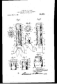
Figure ljisa front view of oiirdevice; the
a outer shell bein'g "shown in section.
Fig. 2 is-a side view, the shell b'eingjshown in section. 1
Fig. 3 is a cross section the-line 3 3 of :Fig. 5--is the top. =0: Fig.1 with a locking keg; inserted Fig. 5.. r
' Fig. 7 is a modification of the locking vice, a pin bein inserted for the locking key.
Fig. 8-is the ower end of .the well casing constructed for using our device for rotary drilli g '-.-Numeral 7 indicates the lower end of a I I working shell in well-work. Shell 7 is rovided with a concentric bore: 8, into w ich all- -the opzerati'ng parts of our device are inserted.
i ear the termination of bore 8 are ig. 6 isa cross section on the'line 6-6015 9 and grooves 10 can-be had in a suitable number. as will easily be understood; two beable distance below the grooves 10 the center-block is cut down to a flattened shaft 12, and near the lower end the shaft is still further reduced to receive thenearly semi-cylin-' drical shanks 13 of thecutters 14.
The reduced' portion" is indicated "by 15 and is extended elow. the shell forming an expander 16. for the cutters. Theexpander fermedin thei -center block -Projections Y 16 is beveledat opposite-edges and cooperates with adjacent. cutters to expand the-cutters, when they are retracted, and to bracethem against collapsing'." The'expander lfifhas lugs 17 formed on the op osite ,sidesto prevent the cutters lfrom alling, out incase of a break in the operating rods18l Fig. 3. isa section ove the top ends of the operating rods 18 showing these rods in the spaces formed just 'a between the shell 7 and thefiattened shaft 12 italso shows aconcentric'bore 19 insi'de 20. 1 The bore 19 also forms slots 21 in the sides of the center-block through which the aces on the inside of the operating rods are'inserted to engage with the spring20. The lower ends of the oper ating rods 18 are pivotall mounted in the holes 22 in the cutters 14. he tension of the shell by the operating rods 18, thereby re-. tractin'gthe cutters. .Thecenter-block 11, spring 2 0,und operating rods 18 form a cutter supporter. 1
The shanks 13. 0f the cutters'14 are conounding surfaces. As the-shell 7 forms a 1 ull 'ring end, the cutters are rovided with shouldersor ofi-sets 23 to uti ize this ring,
tportionately .large pounding g h (tilting movement caused by the cutting p es- -isure'against the cutting] edges 24 of cutters forming a "pro surface and a.
ulcrum for the cutters.
14 is counterbalanced, y the resistance in theilong surface along the edge25 of the shanks 13. 'Theopposite edgeis mutilated and formed. to prevent the cutters from col- I lapsing, theedges 26 and 27' of .the shank 13 -structe'd to form strong counter-levers and engaging with the ' projections 28 and 29 on I the flattened shaft. To make the cutters callapse, as indicated in dotted lines in Fig. 1, the cutters are pulled out of, or protracted from the shell far enough to disengage the 29, the pulling being done against the tension of spring 20. s
- For taking our reamer apartin the collapsed position, the wholeoperating parts,
'cuttershanks and center-block can'be pushed in a suitable distance to bring the projections 9 in the shell 7 to the horizontal part of the grooves l0 along whichthey may be turned to thevertical part of the groove, which are open to' the upper end of the center-block 11.
To prevent disengagement of the centerblock from the shell while operating with our reamer in a well, we provide a locking key asshown in Figs. 5 and 6. The key 30 is a straight fiat steel bar inserted'into a slot 31 which is cut through the whole thick.- ness of the center-block, but not through the shell. The key 30 when the underreamer isin an upright position will fall down to lock the projections 9 of the shell 7 in the grooves 10 of the center-block. The center block can only be unlocked by turning the whole reamer Lip-side down. A modification of our locking device is shown in Fig. 7 where a pin 32 is inserted through the shell and center-block. The
pin 32 is provided with a 'projection 33 which can be inserted through a notch 34 in the washer 35. The projection 33 turns on the inside of these shoes to allow water to passthrough to the cutting edges 24. p v
Incase of a break in th operating rods 18 the cutters 14: are provi ed with recesses 39, see Fig. 4, to engage with the lugs 17 'on the expander 16, see Fig.2, preventing the cutters from falling out of the shell.
Whatwe claim is:
1.; A." device for the purpose described, consisting of a shell having a concentric bore with a projection formed near the inner termination of the bore, a center-block inserted into the bore of the shell being to fit in the nearly semi-circular spaces left on both sides of the center-block in the shell, a spring inserted into the hollow center-block, and operating rods with the lower edges 26 and 27 from the projections 28 and ends turnably secured to the shanks of the cutters and the upper ends engaged with the spring in the center-blockfor holding the "cutters in operating position. 2. A device for the purpose described, consisting of a hollow shell, a center-block removably secured in the shell, cutters slidingly mounted in the space formed between the center-block and the shell, and a well casing being cut out-at thelower termina tion to fit over the cutters, designed for '30 rotary drilling and having grooves provided along the inside of the lower thickerend in the casing adapted to allow water to pass. to the (cutters.
3. A device for' thepurpose described, consisting of a hollow -shell terminating in a circular ring, a round center-block removably secured in, the shell being hollow at the upper end and flattened at the lower end, projections formed on the flattened part 'of the center-block, cutters having shanks formed on the upper ends slidingly fitting in "-the nearly semi-circular spaces formed on both sides of the flattened centerblock in the shell andhaving shoulders to utilize the ring termination of the shell'for' a pounding surface, the cutters having cut ting edges on the lower end concentric to the center of the device, said shanks having straight edges parallel to the center of the device opposite tofthe -cutting edges, the edge-of the shank opposite to the straight edge and on the same side with the cutting edges being' formed to engage with projections on the center block to prevent the cutters from collapsing, and operating means secured to thecu'tters adapted to hold the cutters in operating position.
4. In adevice for the purpose described, a hollow shell, a center-block remova'bly secured in the shell being flattened at the lower end, cutters slidingly mounted in the spaces formed between the flattened center-block and the shell, said center block having'lugs formed on 'the termination of the flattened end, and said cutters having recesses formed on the sides towardthe center-block adapted toengage with the lugs on the center-block to prevent the cutters from falling out. I
5. In a device for the purpose described,
a hollow shell, a center-block removably secured "in the shell being flattened at the lower end," cutters slidingly mounted in the spaces formed between the flattened centerblock and the shell, said center-block terminating below the shell having means thereon to prevent the cutters from collapsing and also adapted to serve as a guide to bring the cutters into operating position,'130
and operating. means secured to the cutters, adapted to hold the cutters in operating position, all substantially as described.
6. In a device for the purpose described, the combination of a hollow shell, a centerblockzremovably secured in the shell being flattened at the lower end, said'center-block being also provided with a slot crosswise through the upper end, cutters slidingly .mounted in the spaces formed between the having shanks on the upper ends slidingly mounted in the nearly semi-circular spaces formed on both sides of the flattened centerblock in the lower end of the shell and having cutting edges formed on the lower ends of the cutters projecting oflthe shell in right angles to the fiat circular shanks.
8. In a device of the class described, the combination with a hollow shell, of cutters slidingly mounted therein; and a cutter supside of the nearly semiporter normally fixed within said-shell, said supporter comprising means slidingly and pivotally securing said cutters to said sup: porterso that said cutters may be collapsed on protraction of the latter, and means located so as to be interposed between said cutters to expand and prevent collapse of the latter when retracted.
9. In a device of the class described, the combination with a hollow shell, of cutters slidingly mounted therein; a cutter su porternormally fixed within said shell; said supporter comprising means slidingly and pivotally securing said cutters to said supporter so that said cutters may be collapsed on protraction of the latter, means located so as to be interposed between said cutters to expand and prevent collapse of the latter when retracted; and means tending to retract said cutters.
10. In a device of the class described, the combination with a hollow shell, of cutters slidingly anounted therein, said cutters'having an olfset disposed to engage the lower face of said shell; and a cutter supporter normally fixed within said shell, said supporter comprising means slidingly and piv-. otally securing said cutters to said supporter so that said cutters may be collapsed on protraction of the latter, and means located so as to be interposed between said cutters to expand and prevent collapse of the latter when retracted.
11. In a deviceof the class described, the combination with a hollow shell of cutters slidingly mounted therein, said cutters having an off-set disposed to engage the lower face of said shell; a cutter supporter normally fixed within said shell, said supporter comprising means slidingly and pivotally securing said cutters to said supporter, so that said cutters, may be collapsed on protraction of the latter, means located so as to be interposed between said cutters to expand and prevent collapse of the latter when retracted; and, means tending to retract said cutters. i I
12. In a device of the class described, the combinationwith a hollow shell, of cutters having shanks slidingly disposed within said shell and disposed to engage the wall of the,
bore of said shell,said cutters provided with off-sets disposed to engage the lower face of said shellxand cooperate therewith to prevent tilting of the cutters outwardly; and a cutter supporter normally fixed within said shell, said supporter comprising means slidingly and pivotally securing said cutters to said supporter so that said cutters may be collapsed on protraction of the latter, and
means located so as to be interposed between said cutters to expand and prevent collapse of the latter when retracte 13. In a device of the class described, the combination with a hollow shell, of cutters havingshanks slidingly disposed within said shell, said cutters provided with off-sets disposed to engage the lower face of said shell and cooperate therewith to prevent tilting of the cutters outwardly; a cutter supporter normally fixed within said shell, said supporter comprising means slidingly and pivotally securing said cutters to said supporter so that said cutters may be collapsed on protraction of the latter, means located so as to be interposed between said cutters to expand and prevent collapse of the latter .when'retracted; and means tending to retract said cutters.
14. In a device of the class described. the combination with a hollow shell, of cutters having shanks slidingly mounted within said shell, said cutters pivotally mounted with respect to one another,- the near faces of-said shanks being in planes at right angles to the cutting edges of said cutters, said shanks dis posed to engage the wall of the bore of said shell, off-sets on said cutters disposed to engage the lower face of said shell and cooperate with said shanks to prevent tilting of the cutters outwardly, said shell being provided with means affixed thereto and interposed between said cutters to expand the latter on retraction of said cutters and to permit collapse of the cutters on protraction.
15. In a device of the class described, the combination with-ahollow shell, of cutters having shanks slidingly mounted within said shell, said cutters pivotally mounted with respect to one another, the near faces of said shanks being in planes at right angles to the cutting edges of said cutters, said shanks disposed to engage the-wall of the bore of said shell, off-sets on said cutters disposed to engage the lower face of said shell and cooperate with said shanks to preventtiltin'g of the cutters outwardly, said shell being near faces of said shanks being substantially at right angles to the cutting edges of said cutters, shoulders on said cutters disposed to engage the lower face of said shell forming a complete ring aboutthe pair of cutters, and means to slidingly and pivotal'ly support said cutters from said supporter.
17 In a device of the class described, the combination with a hollow shell, of a pair of collapsible cuttersslidingly mounted in said. shell, said cutters having nearly semicylindifical shanks, the planes of the near faces of said shanks being substantially at right angles to the cutting edges of said cutters, shoulders on said cutters disposed to engage the lower face of said shell forming a complete ring about the pair of cutters, Ineanslto slidingly and pivotally support said cutters from said shell, and means affixed to said shell disposed so as to be interposed between said cutters when expanded. 18. In a device of the class described, the
combination with a hollow shell, of a pair of collapsible cutters slidingly mounted in said shell, said cutters having nearly semicylindrical shanks, the planes of the near faces of said shanks substantially at right angles to the cutting edges of said cutters,
shoulders on said cutters disposed to engage the lower faceof said shell forming a complete ring about the pair of cutters; and
a cutter supporter afiixed to said shell com prising means slidingly and pivotally supporting said cutters, and 'meansdisposed so as to be interposed between said cutters when expanded. I
19. In a. device of the class described, the
combination with a hollow shell, of a pair of collapsible cutters, said cutters having nearly semi-cylindrical shanks, the planes of the near faces of said shanks being substantially at right angles to the cutting 'faces of said shanks being substantially at right angles to'the cutting'edges of said P cutters,- shoulders on saidcutters disposed to engage the lower face of said shell form'- ters, means to slidingly and pivotally sup port said cutters from said shell, means afing a complete ring about the pair of cutfixed to said shell disposed so as to be interposed between said cutters when expanded,
and means tending to retract said cutters.
21. In a device of the class described, the
combination with a hollow shell, of a pair of collapsible cutters slidingly mounted in said shell, said cutters having nearly semicylindrical shanks, the planes of the near faces of said shanks substantially at right angles to the cutting edges of said cutters, shoulders on said cutters disposed to engage the lower face of said shell forming a complete ring about the pair of cutters; and a cutter supporter afiixed to said shell comprising means slidingly and pivotally supporting said cutters, means disposed so as to be interposed between said cutters when expanded, and means tending to retract said cutters.
LAWRENCE s. CAMPBELL. JOHN GRANT.
Family
ID=
Similar Documents
| Publication | Publication Date | Title |
|---|---|---|
| US6189618B1 (en) | Wellbore wash nozzle system | |
| US946060A (en) | Post-hole auger. | |
| US2882019A (en) | Self-cleaning collapsible reamer | |
| USRE14301E (en) | campbell | |
| US1764373A (en) | Combination expansion mill and underreamer | |
| US1295969A (en) | Rotary boring-drill. | |
| US2204908A (en) | Bicycle lock | |
| US1635601A (en) | Window guard | |
| US1169922A (en) | Combination bit and rotary underreamer. | |
| US1195745A (en) | Benjamin snydeb | |
| US1667190A (en) | Rotary underreamer | |
| US1607430A (en) | Casing protector | |
| US1558596A (en) | Centrifugal reamer for oil wells and the like | |
| US1131928A (en) | Underreamer. | |
| US2093633A (en) | Core drill | |
| US1819273A (en) | Expansible fish tail bit | |
| US1824268A (en) | Expansion drilling bit | |
| US636405A (en) | Rotary and folding chair. | |
| US1803669A (en) | Compound expanding underreamer | |
| US1159172A (en) | Well-boring tool. | |
| US534088A (en) | Combination-lock | |
| US1953292A (en) | Lock | |
| US1960639A (en) | Land anchor | |
| US1870135A (en) | Drill | |
| US176214A (en) | Improvement in step-ladders |